EP4134829B1 - Seitenaustauschverfahren, speichersystem und elektronische vorrichtung - Google Patents
Seitenaustauschverfahren, speichersystem und elektronische vorrichtung Download PDFInfo
- Publication number
- EP4134829B1 EP4134829B1 EP21797595.2A EP21797595A EP4134829B1 EP 4134829 B1 EP4134829 B1 EP 4134829B1 EP 21797595 A EP21797595 A EP 21797595A EP 4134829 B1 EP4134829 B1 EP 4134829B1
- Authority
- EP
- European Patent Office
- Prior art keywords
- swap
- page
- out page
- memory
- swapped
- Prior art date
- Legal status (The legal status is an assumption and is not a legal conclusion. Google has not performed a legal analysis and makes no representation as to the accuracy of the status listed.)
- Active
Links
Images


Classifications
-
- G—PHYSICS
- G06—COMPUTING OR CALCULATING; COUNTING
- G06F—ELECTRIC DIGITAL DATA PROCESSING
- G06F12/00—Accessing, addressing or allocating within memory systems or architectures
- G06F12/02—Addressing or allocation; Relocation
- G06F12/08—Addressing or allocation; Relocation in hierarchically structured memory systems, e.g. virtual memory systems
- G06F12/12—Replacement control
- G06F12/121—Replacement control using replacement algorithms
- G06F12/123—Replacement control using replacement algorithms with age lists, e.g. queue, most recently used [MRU] list or least recently used [LRU] list
-
- G—PHYSICS
- G06—COMPUTING OR CALCULATING; COUNTING
- G06F—ELECTRIC DIGITAL DATA PROCESSING
- G06F12/00—Accessing, addressing or allocating within memory systems or architectures
- G06F12/02—Addressing or allocation; Relocation
- G06F12/08—Addressing or allocation; Relocation in hierarchically structured memory systems, e.g. virtual memory systems
- G06F12/12—Replacement control
- G06F12/121—Replacement control using replacement algorithms
- G06F12/122—Replacement control using replacement algorithms of the least frequently used [LFU] type, e.g. with individual count value
-
- G—PHYSICS
- G06—COMPUTING OR CALCULATING; COUNTING
- G06F—ELECTRIC DIGITAL DATA PROCESSING
- G06F12/00—Accessing, addressing or allocating within memory systems or architectures
- G06F12/02—Addressing or allocation; Relocation
- G06F12/08—Addressing or allocation; Relocation in hierarchically structured memory systems, e.g. virtual memory systems
- G06F12/0802—Addressing of a memory level in which the access to the desired data or data block requires associative addressing means, e.g. caches
- G06F12/0862—Addressing of a memory level in which the access to the desired data or data block requires associative addressing means, e.g. caches with prefetch
-
- G—PHYSICS
- G06—COMPUTING OR CALCULATING; COUNTING
- G06F—ELECTRIC DIGITAL DATA PROCESSING
- G06F12/00—Accessing, addressing or allocating within memory systems or architectures
- G06F12/02—Addressing or allocation; Relocation
- G06F12/08—Addressing or allocation; Relocation in hierarchically structured memory systems, e.g. virtual memory systems
- G06F12/0802—Addressing of a memory level in which the access to the desired data or data block requires associative addressing means, e.g. caches
- G06F12/0866—Addressing of a memory level in which the access to the desired data or data block requires associative addressing means, e.g. caches for peripheral storage systems, e.g. disk cache
- G06F12/0868—Data transfer between cache memory and other subsystems, e.g. storage devices or host systems
-
- G—PHYSICS
- G06—COMPUTING OR CALCULATING; COUNTING
- G06F—ELECTRIC DIGITAL DATA PROCESSING
- G06F12/00—Accessing, addressing or allocating within memory systems or architectures
- G06F12/02—Addressing or allocation; Relocation
- G06F12/08—Addressing or allocation; Relocation in hierarchically structured memory systems, e.g. virtual memory systems
- G06F12/12—Replacement control
- G06F12/121—Replacement control using replacement algorithms
- G06F12/126—Replacement control using replacement algorithms with special data handling, e.g. priority of data or instructions, handling errors or pinning
-
- G—PHYSICS
- G06—COMPUTING OR CALCULATING; COUNTING
- G06F—ELECTRIC DIGITAL DATA PROCESSING
- G06F2212/00—Indexing scheme relating to accessing, addressing or allocation within memory systems or architectures
- G06F2212/10—Providing a specific technical effect
- G06F2212/1016—Performance improvement
- G06F2212/1024—Latency reduction
Definitions
- This application relates to the field of memory management technologies, and in particular, to a page swap method, a storage system, and an electronic device.
- a terminal device With an increasing usage rate of a terminal device by a user, more and more applications are installed by the user, and requirements of various applications for a memory capacity of the terminal device are also growing. For example, a plurality of common applications such as a chat application, a game application, and a camera application each occupy the memory capacity of the terminal device by kilomegabyte (kilomegabyte, GB). However, the memory capacity of the terminal device is limited.
- a system may reclaim some pages, such as pages used for mapping a process heap, a stack, a data segment, and a shared memory (shmem), to other space based on a page swap technology.
- pages such as pages used for mapping a process heap, a stack, a data segment, and a shared memory (shmem), to other space based on a page swap technology.
- a page is a minimum unit of address space in a memory management process.
- EP 3 514 689 A1 describes a memory management method to resolve an existing problem that a memory reclaiming rate is relatively low, severely affecting memory allocation performance in a scenario in which system memory is insufficient.
- This application provides a page swap method, a storage system, and an electronic device, to improve accuracy of page swapping and running performance of a system in a page swap process.
- a page swap method is provided.
- the method is applied to a storage system including a processor, a memory device, and a swap device, the memory device stores a plurality of pages of different applications, and the method includes: determining, from a least recently used LRU linked list, a to-be-swapped-out first swap-out page of the memory device; determining a second swap-out page from the LRU linked list based on the first swap-out page; and when the first swap-out page is swapped out of the memory device, consecutively swapping out the first swap-out page and the second swap-out page to the swap device.
- the page swap method for one of to-be-swapped-out pages in the LRU linked list, one or more other to-be-swapped-out pages belonging to a same application as the one to-be-swapped-out page are determined based on the one to-be-swapped-out page. Further, in a page swap-out process, the pages that belong to the same application and that are in the to-be-swapped-out pages are preferentially swapped out consecutively, and swap-out pages that belong to the same application are stored consecutively in the swap device. In the page swap-out process, logically related pages of a same application can be stored consecutively based on a logical correlation of the to-be-swapped-out pages and an LRU linked list sequence.
- the first swap-out page and the second swap-out page have a same application identifier
- the determining a second swap-out page from the LRU linked list based on the first swap-out page includes: determining the application identifier of the first swap-out page, and determining, from the LRU linked list, a to-be-swapped-out page that has a same application identifier as the first swap-out page, as the second swap-out page.
- each application (application, APP) used by a user has a unique identifier (identifier, ID).
- ID identifier
- a memory capacity may be applied for in sequence, and different areas are divided for different applications based on a user request.
- Each service may include a plurality of processes, and each service may have a fixed identifier or each process may have a different identifier.
- the system in addition to the application identifier, the system may further perform the page swap-out process based on a process identifier or a service identifier.
- a system may determine, based on a service identifier, to swap out a page having the same service identifier to the swap device.
- a page swap-in process an adjacent page having the same service identifier as a target page is swapped into the memory device.
- a system may determine, based on a process identifier, to swap out a page having the same process identifier to the swap device.
- a page swap-in process an adjacent page having the same process identifier as a target page is swapped into the memory device. This is not limited in this embodiment of this application.
- the memory device stores a memory mapping table
- the memory mapping table is used to indicate a correspondence between a logical address and an application identifier of each of the plurality of pages
- the determining a second swap-out page from the LRU linked list based on the first swap-out page includes: obtaining a logical address of the first swap-out page; determining the application identifier of the first swap-out page based on the memory mapping table and the logical address of the first swap-out page; and determining, from the LRU linked list, the to-be-swapped-out page that has the same application identifier as the first swap-out page, as the second swap-out page.
- an application identifier of each page is further determined by determining a logical address of each to-be-swapped-out page, to determine to-be-swapped-out pages belonging to a same application.
- the pages that belong to the same application and that are in the to-be-swapped-out pages are preferentially swapped out consecutively, and swap-out pages that belong to the same application are stored consecutively in the swap device.
- logically related pages of a same application can be stored consecutively based on a logical correlation of the to-be-swapped-out pages and an LRU linked list sequence.
- the memory device in this embodiment of this application includes a memory manager, and the memory manager may maintain the memory mapping table.
- the application A When the user uses an application A, the application A requests a memory capacity from the processor, and the processor may obtain an ID of the application A, and allocate, based on a request of the application A and in the memory device, a memory area whose logical address is PGD 1 to the application A and a memory area whose logical address is PGD 2 to an application B. Accordingly, the memory mapping table of the system may be obtained, and the memory manager of the memory device may store the memory mapping table.
- the method further includes: in response to a swap-in request for the target page, swapping the target page from the swap device to the memory device, and preloading the adjacent page of the target page.
- the target page and the adjacent page of the target page may be swapped into the memory device, or the target page is swapped in from the swap device to the memory device, and the adjacent page of the target page is preloaded.
- preloading may be implemented by the memory manager by using a cache (cache). Details are not described herein again. This process can ensure that a swap-in page is a logically related page of a same application, so that prefetch accuracy in the swap-in process is improved. This improves running performance of the system.
- the consecutively swapping out the first swap-out page and the second swap-out page to the swap device includes: simultaneously swapping out the first swap-out page and the second swap-out page to the swap device; or consecutively swapping out the first swap-out page and the second swap-out page to the swap device in a first sequence.
- the first sequence is an arrangement sequence of pages with a same application identifier in the LRU linked list.
- the logical address of each of the plurality of pages is a page global directory PGD address.
- the method further includes: determining a quantity of the to-be-swapped-out pages according to a space capacity of the memory device; and determining a quantity of the to-be-swapped-in target pages according to the space capacity of the memory device.
- an electronic device includes a processing unit, a memory device, and a swap device, the memory device stores a plurality of pages of different applications, and the processing unit is configured to: determine, from a least recently used LRU linked list, a to-be-swapped-out first swap-out page of the memory device; determine a second swap-out page from the LRU linked list based on the first swap-out page; and when the first swap-out page is swapped out of the memory device, consecutively swap out the first swap-out page and the second swap-out page to the swap device.
- the first swap-out page and the second swap-out page have a same application identifier
- the processing unit is specifically configured to: determine the application identifier of the first swap-out page, and determine, from the LRU linked list, a to-be-swapped-out page that has a same application identifier as the first swap-out page, as the second swap-out page.
- the memory device stores a memory mapping table
- the memory mapping table is used to indicate a correspondence between a logical address and an application identifier of each of the plurality of pages
- the electronic device further includes: an obtaining unit, configured to obtain a logical address of the first swap-out page.
- the processing unit is further configured to: determine the application identifier of the first swap-out page based on the memory mapping table and the logical address of the first swap-out page; and determine, from the LRU linked list, the to-be-swapped-out page that has the same application identifier as the first swap-out page, as the second swap-out page.
- the processing unit is further configured to: in response to a swap-in request for a target page, swap the target page from the swap device to the memory device, and preload an adjacent page of the target page.
- the processing unit is specifically configured to: simultaneously swap out the first swap-out page and the second swap-out page to the swap device; or consecutively swap out the first swap-out page and the second swap-out page to the swap device in a first sequence.
- the first sequence is an arrangement sequence of pages with a same application identifier in the LRU linked list.
- the logical address of each of the plurality of pages is a page global directory PGD address.
- the processing unit is further configured to: determine a quantity of the to-be-swapped-out pages according to a space capacity of the memory device; and determine a quantity of the to-be-swapped-in target pages according to the space capacity of the memory device.
- an electronic device including: one or more processors; a memory; a memory device and a swap device; a plurality of applications; and one or more programs.
- the one or more programs are stored in the memory, and when the one or more programs are executed by the processor, the electronic device is enabled to perform the method according to any one of the first aspect and the implementations of the first aspect.
- an apparatus is provided.
- the apparatus is included in an electronic device, and the apparatus has functions of implementing behavior of the electronic device in the foregoing aspects and the possible implementations of the foregoing aspects.
- the function may be implemented by hardware, or may be implemented by hardware executing corresponding software.
- the hardware or the software includes one or more modules or units corresponding to the function, for example, a display module or unit, a detection module or unit, or a processing module or unit.
- a storage system includes: a memory device and a swap device; and a processor and an interface.
- the processor and the interface cooperate with each other, so that the storage system performs the method according to any one of the first aspect and the implementations of the first aspect.
- this application provides an electronic device, including a touch display.
- the touch display includes: a touch-sensitive surface and a display; a camera; one or more processors; a memory; a memory device and a swap device; a plurality of applications; and one or more computer programs.
- the one or more computer programs are stored in the memory, and the one or more computer programs include instructions.
- the electronic device is enabled to perform the method according to any one of the first aspect and the implementations of the first aspect.
- this application provides an electronic device, including one or more processors and one or more memories.
- the one or more memories are coupled to the one or more processors.
- the one or more memories are configured to store computer program code.
- the computer program code includes computer instructions.
- this application provides a computer-readable storage medium, including computer instructions.
- the computer instructions When the computer instructions are run on an electronic device, the electronic device is enabled to perform the method according to any one of the first aspect and the implementations of the first aspect.
- this application provides a computer program product.
- the computer program product When the computer program product is run on an electronic device, the electronic device is enabled to perform the method according to any one of the first aspect and the implementations of the first aspect.
- first and second are merely intended for a purpose of description, and shall not be understood as an indication or implication of relative importance or implicit indication of a quantity of indicated technical features. Therefore, a feature limited by “first” or “second” may explicitly or implicitly include one or more of the features.
- Embodiments of this application provide a page swap method, which may be applied to a separate storage system, or an electronic device including the storage system, or a separate application.
- the application may implement the page swap method in this application.
- a page is a minimum unit of address space. Generally, a page is 4 kilobytes (kilobyte, KB) or 64 KB.
- Memory space of a process is only a virtual memory, namely, the logical memory.
- the running of a program requires a real physical memory, namely, a random access memory (random access memory, RAM). If necessary, an operating system can map the logical memory applied for during program running to the RAM, so that the process can use the physical memory.
- RAM random access memory
- the logical address space may be divided into a plurality of virtual pages (virtual page, VP) of a fixed size, and a size of the virtual page may be 4 kilobytes (kilobyte, KB).
- Memory space of the physical memory is referred to as the "physical address space”.
- the physical address space may be divided into a plurality of physical pages (physical page, PP) of a fixed size, and a size of the physical page may be 4 KB.
- the virtual page is mapped with a file of a hard disk storage device, and then is cached to a physical page.
- logical addresses are used, and each process maintains a separate page table.
- the page table is an array structure, and stores status information of each virtual page, for example, status information indicating whether each virtual page is mapped or whether each virtual page is cached.
- the zRAM technology can replace a hard disk storage device with the system memory to provide swap space for a system.
- the system memory can be better used until the swap space of the hard disk storage device need to be used, to avoid paging on the hard disk storage device. Therefore, performance is improved.
- an area is allocated from the system memory (RAM) and serves as a swap (swap) area. If space of the system memory is insufficient, memory data occupied by an application is compressed and then is copied to the swap area. When swapping back to the application needs to be performed, the compressed data of the application can be directly restored to the memory. This saves time required for restarting the application. In addition, after the data in the swap area is compressed, more data of different applications can be stored, which expands the size of the system memory (RAM) in another way.
- a system When a process is executed, when a value stored in a logical address needs to be accessed, a system first finds a virtual page (VP) in which the logical address is located, and then finds, based on a page table, a physical page (PP) corresponding to the virtual page (VP) in the page table.
- VP virtual page
- PP physical page
- a kernel's page missing fault handler is invoked. Content of a missed page is cached from a correspondingly mapped file area of the hard disk storage device to a system memory (RAM).
- RAM system memory
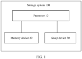
- FIG. 1 is a schematic diagram of a structure of a storage system 100 according to an embodiment of this application.
- the storage system 100 may include a processor 10, a memory device 20, and a swap device 30.
- the processor 10 is a control center or a core component of the storage system 100, or may be a control center of an electronic device including the storage system.
- the processor 10 may be connected to all parts of the entire electronic device through various interfaces and lines.
- the processor 10 By running or executing a software program and/or a module stored in the memory and invoking data stored in the memory, the processor 10 performs various functions of the electronic device and data processing, to perform overall monitoring on the electronic device.
- the processor 10 may control a data processing process, for example, a page swap process and a data read/write process.
- the processor 10 may correspond to a central processing unit (central processing unit, CPU) of the electronic device, and the processor 10 may include one or more processing units.
- the processor 10 may selectively include an arithmetic unit and a controller, may be configured to obtain instructions and process data, and may be specifically configured to perform instruction execution sequence control, operation control, and time control, and perform an arithmetic operation and a logical operation on data, or process other information and the like.
- the memory device 20 is a most common system memory, and may also be referred to as a "memory" or a "system memory”.
- the memory device 20 may maintain data for a very short time. To maintain data, the memory device 20 may store the data by using a capacitor charge, and therefore needs to be refreshed (refresh) at intervals. In addition, if the electronic device is powered off, data stored in the memory device 20 is lost.
- the memory device 20 internally includes a memory manager, the memory manager stores a memory index table, and the memory index table is used to indicate a block management rule of the memory device 20.
- the memory index table may include the page table described above, and is used to indicate a mapping relationship between a virtual page, a physical page, and a file in a hard disk storage device.
- the memory device 20 may be a dynamic random access memory (dynamic random access memory, DRAM).
- DRAM dynamic random access memory
- the swap device 30 is also referred to as a "swap area", and is configured to store a process, data, or the like that is swapped out of the memory device 20. Under a scheduling principle of the processor 10, some processes or data in the memory device 20 may be migrated to the swap device 30, to free up space of the memory device 20, which is referred to as a "swap-out process”. Similarly, under the scheduling principle of the processor 10, some processes or data in the swap device 30 is migrated to the memory device 20, which is referred to as a "swap-in process".
- the swap device 30 may be a storage device independent of the memory device 20, or may be a swap area formed by a part of the memory device 20.
- the swap device 30 may be an area in the DRAM; or the swap device may be an independent storage device, such as a flash memory (NAND flash memory, NAND).
- NAND flash memory NAND flash memory
- page swap some pages can be compressed and then stored in a memory of the mobile phone by using the zRAM technology described above.
- a page missing fault occurs in the system, and the compressed pages are requested to be decompressed and be swapped back to the memory.
- the swap device 30 is an external storage device independent of the memory device 20. During page swap, some pages can be swapped out to the external storage device of the PC. When a user needs to use the swap-out pages, a page missing fault occurs in the system, and the swap-out pages are requested to be swapped into the memory again. This is not limited in this application.
- the processor 10 may write a related process or data of the application A into the memory device 20, and migrate a related process or data of the application B in the memory device 20 to the swap device 30.
- the processor 10 may re-migrate, to the memory device 20, the process or data related to the application B in the memory device 20.
- the storage system 100 may further include one or more interfaces or lines of different types.
- the interface may include an internal interface or an external interface.
- the line may include a system bus, a memory bus, an input/output (input/output, I/O) bus, or the like.
- the interface or the line may be configured to connect modules of the storage system.
- FIG. 1 is merely a schematic diagram of the storage system. For simplicity, FIG. 1 does not show the interface or the line.
- the storage system 100 may alternatively use different interface connection manners, or a combination of a plurality of interface connection manners.
- An interface type and an interface connection manner are not limited in this embodiment of this application.
- the structure shown in this embodiment of this application does not constitute a specific limitation on the storage system 100.
- the storage system 100 may include more or fewer components than those shown in the figure, or combine some components, or split some components, or have different component arrangements.
- the components shown in the figure may be implemented by hardware, software, or a combination of software and hardware.
- the electronic device including the storage system 100 in this application may be a mobile phone, a tablet computer, a wearable device, a vehicle-mounted device, an augmented reality (augmented reality, AR)/virtual reality (virtual reality, VR) device, a notebook computer, an ultra-mobile personal computer (ultra-mobile personal computer, UMPC), a netbook, a personal digital assistant (personal digital assistant, PDA), or the like.
- augmented reality augmented reality
- VR virtual reality
- a notebook computer an ultra-mobile personal computer (ultra-mobile personal computer, UMPC), a netbook
- PDA personal digital assistant
- the foregoing listed electronic devices may further include more other components in addition to the foregoing storage system 100.
- the electronic device may further include one or more of a charging management module, a power management module, a battery, an antenna, a mobile communications module, a wireless communications module, an audio module, a speaker, a receiver, a microphone, a headset jack, a sensor module, a button, a motor, an indicator, a camera, a display, a subscriber identification module (subscriber identification module, SIM) card interface, and the like.
- the sensor module may include a pressure sensor, a gyroscope sensor, a barometric pressure sensor, a magnetic sensor, an acceleration sensor, a distance sensor, an optical proximity sensor, a fingerprint sensor, a temperature sensor, a touch sensor, an ambient light sensor, a bone conduction sensor, and the like.
- a quantity of components included in the terminal device and a type of a component are not limited in this embodiment of this application.
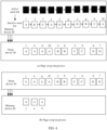
- FIG. 2 is a schematic diagram of an example of a page swap process according to this application.
- figure (a) is a schematic diagram of a page swap-out stage
- figure (b) is a schematic diagram of a page swap-in stage.
- a system kernel maintains an active anon list (active anon list) and an inactive anon list (inactive anon list).
- a page that is determined as cold by a kernel algorithm is swapped from the active anon list (active anon list) to the inactive anon list (inactive anon list).
- pages in the inactive anon list are swapped out of a memory in sequence until a memory requirement is met.
- the swap-out page is swapped into the memory when it is used by a user.
- a page to be swapped out in the inactive anon list is referred to as a "to-be-swapped-out page”
- a page to be swapped in is referred to as a "target page”.
- active pages are listed in the active anon list, and the active page may be understood as a page with a high read frequency of the system or a page related to an application currently running in the system.
- the data is migrated from the active anon list to the inactive anon list, and then is swapped out from the inactive anon list to the swap device 30.
- small boxes in FIG. 2 represent pages of different applications.
- a box A is a page of an application A.
- the sequence is as follows: a page of an application A, a page of an application B, a page of an application C, a page of the application A, a page of an application D, a page of the application A, a page of the application D, a page of the application B, a page of the application C, and a page of the application A, where all the pages are arranged, for ease of description, numbers 1 to 10 are used for marking, and the related pages related to the application A are respectively marked as 1, 4, 6, and 10.
- the related pages 1, 4, 6, and 10 related to the application A are consecutive pages of a logical address of the application A.
- the pages are swapped out only according to the sequence of the LRU linked list, and the swap-out pages are logically not related.
- the pages of the application A, the application B, the application C, the application A, the application D, the application A, the application D, the application B, the application C, and the application A are sequentially swapped out of the inactive anon list, and adjacent pages in the linked list are also adjacently stored in the swap device after being swapped out.
- pages adjacently stored in the swap device may usually belong to different applications and are logically irrelevant. In other words, during page swap, pages of a same application are discretely stored in the swap device.
- a page adjacent to the target page is considered to be swapped in, which is referred to as "prefetch".
- prefetch For example, if the target page is a related page 4 of the application A, adjacent pages of the related page 4 are also swapped in. The adjacent pages are related pages of the application C and the application D. In other words, a large quantity of prefetched pages may not belong to a same application. As a result, prefetch accuracy in the swap-in stage is very low. If a prefetched related page of another application (for example, a related page of the application C and a related page of the application D) is not subsequently used by the system, a memory capacity is occupied, to affect performance of the system.
- a prefetched related page of another application for example, a related page of the application C and a related page of the application D
- pages of consecutive logical addresses are prefetched.
- related pages 1, 4, 6, and 10 of the application A are pages with consecutive logical addresses.
- the target page is swapped in, previous and next pages whose logical addresses are adjacent to that of the target page are swapped back to the memory at the same time.
- the related page 4 of the application A is swapped in, both the related pages 1 and 6 whose logical addresses are adjacent to that of the related page 4 and that are of the application A are also swapped back to the memory.
- the prefetch accuracy is improved to some extent.
- physical addresses of the swap-in related pages 1, 4, and 6 of the application A actually stored in the swap device 30 are nonconsecutive, that is, the prefetched related pages 1, 4, and 6 of the application A are discretely stored in storage space of the swap device 30, and the physical addresses are not adjacent. Performance of a swap-in process of discrete data is low, affecting user experience in using the application A.
- FIG. 3 is a schematic flowchart of an example of a page swap method according to an embodiment of this application.
- the method may be implemented in the storage system 100 shown in FIG. 1 .
- the memory device 20 of the storage system 100 stores a memory mapping table and a plurality of pages of different applications. Specifically, the method may be performed by the processor 10. As shown in FIG. 3 , the method 300 may include the following steps.
- the processor 10 determines, from the plurality of pages stored in the memory device 20, a to-be-swapped-out first swap-out page of the memory device.
- the processor 10 determines a second swap-out page from an LRU linked list based on the first swap-out page.
- first swap-out page herein may be any one of a plurality of to-be-swapped-out pages stored in the memory device 20.
- the first swap-out page is a page in the LRU linked list.
- the first swap-out page and the second swap-out page have a same application identifier
- the processor 10 does determine the application identifier of the first swap-out page, and determine, from the LRU linked list, a to-be-swapped-out page that has a same application identifier as the first swap-out page, as the second swap-out page.
- the processor 10 may obtain a logical address of the first swap-out page, determine the application identifier of the first swap-out page based on the memory mapping table and the logical address of the first swap-out page, and determine, from the LRU linked list, the to-be-swapped-out page that has the same application identifier as the first swap-out page, as the second swap-out page.
- the memory device 20 in this embodiment of this application includes a memory manager.
- the memory manager may maintain the memory mapping table, and the memory mapping table is used to indicate a correspondence between a logical address and an application identifier of the memory device 20.
- the memory mapping table may be generated by the processor 10 and stored in the memory manager of the memory device 20. This is not limited in this embodiment of this application.
- Table 1 is the memory mapping table of an example of the memory device 20 according to this embodiment of this application. As shown in the Table 1, storage space of the memory device 20 may be divided into a plurality of areas. Each area of the memory device has a different logical address, and the logical address may be distinguished by using a page global directory (page global directory, PGD) address.
- PGD page global directory
- each application used by a user has a unique identifier (identifier, ID).
- identifier ID
- a memory capacity may be applied for in sequence, and different areas are divided for different applications based on a user request.
- the application A requests a memory capacity from the processor 10, and the processor 10 may obtain an ID of the application A, and allocate, based on a request of the application A and in the memory device 20, a memory area whose logical address is PGD 1 to the application A and a memory area whose logical address is PGD 2 to an application B.
- the memory mapping table as shown in Table 1 may be obtained, and the memory manager of the memory device 20 may store the memory mapping table.
- Table 1 Logical address Application identifier PGD 1 Application A PGD 2 Application B PGD 3 Application C PGD 4 Application A PGD 5 Application D PGD 6 Application A PGD 7 Application D PGD 8 Application B PGD 9 Application C PGD 10 Application A ... ...
- a logical address of a to-be-swapped-out page is determined based on the LRU linked list.
- logical backtracking is performed on each page in an inactive anon list or an active anon list, to determine a logical address of each page.
- a logical backtracking process of each page may be understood as: determining a logical address of the page level by level based on a structure of a page table. For example,
- vm_area_struct *vm, mm_ struct *mm, and pgd_t*pgd may be understood as pointer addresses.
- a data structure is not limited in this application. Regardless of a quantity of levels of data structures, the base address of a level-1 page table to which a PGD pointer points may be determined according to the foregoing logical backtracking method, so that the logical address of the to-be-swapped-out page is determined.
- an application identifier corresponding to the to-be-swapped-out page may be learned according to the memory mapping table, that is, the application A to which the to-be-swapped-out page belongs is determined.
- the logical address of each page may be determined for the pages in the active anon list, or the logical address of each page may be determined for the pages in the inactive anon list. This is not limited in this embodiment of this application. Determining the logical address of each page in the inactive anon list can reduce a quantity of pages whose logical addresses need to be determined, and therefore, an operation amount of the processor 10 can be reduced to some extent.
- the system may determine that the to-be-swapped-out page belongs to a same application. Therefore, it may be determined, based on this, which pages in the to-be-swapped-out pages in the LRU linked list are logically related pages belonging to a same application.
- the pages having the same application ID are consecutively swapped out to the swap device 30, so that it can be ensured that the pages swapped out to the swap device 30 are logical consecutive pages.
- the logical consecutive pages are stored together, and may have consecutive physical addresses.
- related pages 1, 4, 6, and 10 of the application A are consecutively swapped out to the swap device 30, and physical addresses occupied by the related pages 1, 4, 6, and 10 of the application A in the swap device 30 are also consecutive.
- this process can implement consecutive storage of logically related pages of a same application.
- the physical addresses of the related pages 1, 4, 6, and 10 of the application A in the swap device 30 are consecutive, so that spatial locality of the zRAM can be improved.
- the target page is swapped from the swap device to the memory device in response to the swap-in request for the target page, and an adjacent page of the target page is preloaded.
- the processor 10 in response to the swap-in request for the target page, the processor 10 simultaneously swaps the target page and the adjacent page of the target page to the memory device 20.
- the target page is swapped from the swap device to the memory device, and the adjacent page of the target page is preloaded.
- preloading may be implemented by a memory manager by using a cache (cache). Details are not described herein again.
- the logically related pages are also consecutively stored in the swap device 30, that is, physical address continuity is implemented.
- the target page and a page adjacent to the target page may be swapped into the memory according to a prefetch principle. This prefetch process can ensure that a swap-in page is a logically related page of a same application, so that prefetch accuracy in the swap-in process is improved.
- an application ID of each page is further determined by determining a logical address of each to-be-swapped-out page, to determine to-be-swapped-out pages belonging to a same application.
- the pages that belong to the same application and that are in the to-be-swapped-out pages are preferentially swapped out consecutively, and swap-out pages that belong to the same application are stored consecutively in the swap device.
- logically related pages of a same application can be stored consecutively based on a logical correlation of the to-be-swapped-out pages and an LRU linked list sequence.
- the target page and the page adjacent to the target page are swapped into the memory according to a prefetch principle, so that it can be ensured that a swap-in page is a logically related page of a same application, thereby improving prefetch accuracy in the swap-in process.
- This improves running performance of a system.
- system may further determine, based on a service identifier or a process identifier, to swap pages having a same service identifier or a same process identifier out of the swap device.
- each service may include a plurality of processes, and each service may have a fixed identifier or each process may have a different identifier.
- the system in addition to the application identifier, the system may further perform the page swap-out process based on a process identifier or a service identifier.
- a system may determine, based on a service identifier, to swap out a page having the same service identifier to the swap device.
- a page swap-in process an adjacent page having the same service identifier as a target page is swapped into the memory device.
- a system may determine, based on a process identifier, to swap out a page having the same process identifier to the swap device.
- a page swap-in process an adjacent page having the same process identifier as a target page is swapped into the memory device. This is not limited in this embodiment of this application.
- FIG. 5 is a schematic diagram of a structure of an example of an electronic device 500 according to an embodiment of this application.
- the electronic device 500 includes an obtaining unit 510, a processing unit 520, a memory device 20, and a swap device 30.
- the memory device 20 stores a memory mapping table and a plurality of pages of different applications.
- the memory mapping table is used to indicate a correspondence between a logical address and an application identifier of each of the plurality of pages.
- the electronic device includes the obtaining unit 510 and the processing unit 520.
- the processing unit 520 is configured to determine, from a least recently used LRU linked list, a to-be-swapped-out first swap-out page of the memory device.
- the processing unit 520 is further configured to: determine a second swap-out page from the LRU linked list based on the first swap-out page; and when the first swap-out page is swapped out of the memory device 20, consecutively swap out the first swap-out page and the second swap-out page to the swap device 30.
- the first swap-out page and the second swap-out page have a same application identifier
- the processing unit 520 is specifically configured to: determine the application identifier of the first swap-out page, and determine, from the LRU linked list, a to-be-swapped-out page that has a same application identifier as the first swap-out page, as the second swap-out page.
- the memory device stores the memory mapping table, and the memory mapping table is used to indicate the correspondence between the logical address and the application identifier of each of the plurality of pages.
- the obtaining unit 510 is configured to obtain a logical address of the first swap-out page; and the processing unit 520 is further configured to: determine the application identifier of the first swap-out page based on the memory mapping table and the logical address of the first swap-out page; and determine, from the LRU linked list, the to-be-swapped-out page that has the same application identifier as the first swap-out page, as the second swap-out page.
- the processing unit 520 is further configured to: when receiving a swap-in request for a target page, swap the target page from the swap device 30 to the memory device 20 in response to the swap-in request for the target page, and preload an adjacent page of the target page.
- the electronic device 500 may further include more functional modules, or two or more functions may be integrated into one processing module.
- Each functional module may implement the page swap method 300 in FIG. 3 , and is configured to perform corresponding steps in the method 300.
- FIG. 3 For brevity, details are not described herein again.
- the page swap method in this application may be applied to the storage system 100 shown in FIG. 1 , or may be applied to an electronic device such as a mobile phone, a tablet, a PC, or a smartwatch.
- a page swap process storage continuity of logically related pages in a swap-out stage is ensured.
- a page swap-in process it is ensured that a swap-in page is a logically related page of a same application, so that prefetch accuracy in the swap-in process is improved. This improves performance of the system.
- the electronic device when the page swap method is applied to the electronic device such as the mobile phone, the tablet, the PC, or the smartwatch, to implement the foregoing functions, the electronic device includes corresponding hardware and/or software modules for performing the functions.
- Algorithm steps in the examples described with reference to embodiments disclosed in this specification can be implemented by hardware or a combination of hardware and computer software in this application. Whether a function is performed in a manner of hardware or hardware driven by computer software depends on particular applications and design constraints of the technical solutions. A person skilled in the art may use different methods to implement the described functions for each particular application with reference to embodiments, but it should not be considered that the implementation goes beyond the scope of this application.
- the electronic device may be divided into functional modules based on the foregoing method examples.
- each functional module may be obtained through division based on corresponding functions, or two or more functions may be integrated into one processing module.
- the integrated module may be implemented in a form of hardware. It should be noted that, in embodiments, division into modules is an example and is merely logical function division. During actual implementation, there may be another division manner.
- the electronic device may include a display unit, a detection unit, and a processing unit. It should be noted that all related content of the steps in the foregoing method embodiments may be cited in function description of corresponding functional modules. Details are not described herein again.
- the electronic device provided in embodiments is configured to perform the page swap method. Therefore, an effect same as the effect of the foregoing implementation methods can be achieved.
- the electronic device may include a processing module, a storage module, and a communications module.
- the processing module may be configured to control and manage actions of the electronic device, for example, may be configured to support the electronic device in performing the steps performed by the display unit, the detection unit, and the processing unit.
- the storage module may be configured to support the electronic device to store program code, data, and the like.
- the communications module may be configured to support communications between the electronic device and another device.
- the processing module may be a processor or a controller.
- the processor may implement or execute various example logical blocks, modules, and circuits described with reference to content disclosed in this application.
- the processor may alternatively be a combination of processors implementing a computing function, for example, a combination of one or more microprocessors or a combination of a digital signal processor (digital signal processor, DSP) and a microprocessor.
- the storage module may be a memory.
- the communications module may be specifically a device that interacts with another electronic device, such as a radio frequency circuit, a Bluetooth chip, or a Wi-Fi chip.
- the processing module may be a processor
- the storage module is a memory
- the electronic device in this embodiment may be a mobile phone, a tablet, a PC, a smartwatch, or the like.
- An embodiment further provides a computer storage medium.
- the computer storage medium stores computer instructions.
- the computer instructions When the computer instructions are run on an electronic device, the electronic device is enabled to perform the related method steps, to implement the page swap method in the foregoing embodiments.
- An embodiment further provides a computer program product.
- the computer program product When the computer program product is run on a computer, the computer is enabled to perform the foregoing related steps, to implement the page swap method in the foregoing embodiments.
- an embodiment of this application further provides an apparatus.
- the apparatus may be specifically a chip, a component, or a module.
- the apparatus may include a processor and a memory that are connected to each other.
- the memory is configured to store computer-executable instructions.
- the processor may execute the computer-executable instructions stored in the memory, to enable the chip to perform the page swap method in the foregoing method embodiments.
- the electronic device, the computer storage medium, the computer program product, and the chip provided in the embodiments are all configured to perform a corresponding method provided above. Therefore, for beneficial effects that can be achieved by the electronic device, the computer storage medium, the computer program product, and the chip, refer to beneficial effects of the corresponding method provided above. Details are not described herein again.
- the disclosed apparatus and method may be implemented in other manners.
- the described apparatus embodiment is merely an example.
- the module or division into the units is merely logical function division and may be other division in actual implementation.
- a plurality of units or components may be combined or integrated into another apparatus, or some features may be ignored or not performed.
- the displayed or discussed mutual couplings or direct couplings or communication connections may be implemented through some interfaces.
- the indirect couplings or communication connections between the apparatuses or units may be implemented in electronic, mechanical, or other forms.
- the units described as separate parts may or may not be physically separate, and parts displayed as units may be one or more physical units, may be located in one place, or may be distributed on different places. Some or all of the units may be selected based on actual requirements to achieve the objectives of the solutions of embodiments.
- functional units in embodiments of this application may be integrated into one processing unit, each of the units may exist alone physically, or two or more units are integrated into one unit.
- the integrated unit may be implemented in a form of hardware, or may be implemented in a form of a software functional unit.
- the integrated unit When the integrated unit is implemented in a form of a software functional unit and sold or used as an independent product, the integrated unit may be stored in a readable storage medium.
- the software product is stored in a storage medium and includes several instructions for instructing a device (which may be a single-chip microcomputer, a chip, or the like) or a processor (processor) to perform all or some of the steps of the methods described in embodiments of this application.
- the foregoing storage medium includes any medium that can store program code, such as a USB flash drive, a removable hard disk, a read-only memory (read-only memory, ROM), a random access memory (random access memory, RAM), a magnetic disk, or an optical disc.
- program code such as a USB flash drive, a removable hard disk, a read-only memory (read-only memory, ROM), a random access memory (random access memory, RAM), a magnetic disk, or an optical disc.
Landscapes
- Engineering & Computer Science (AREA)
- Theoretical Computer Science (AREA)
- Physics & Mathematics (AREA)
- General Engineering & Computer Science (AREA)
- General Physics & Mathematics (AREA)
- Memory System Of A Hierarchy Structure (AREA)
Claims (15)
- Seitenaustauschverfahren, wobei das Verfahren auf ein Speichersystem angewendet wird, das einen Prozessor, eine Speichervorrichtung und eine Austauschvorrichtung umfasst, die Speichervorrichtung eine Vielzahl von Seiten verschiedener Anwendungen speichert und das Verfahren Folgendes umfasst:Bestimmen (301), aus einer am längsten nicht verwendeten(LRU)-verketteten Liste, einer auszulagernden ersten Auslagerungsseite der Speichervorrichtung;Bestimmen (302) einer zweiten Auslagerungsseite aus der LRU-verketteten Liste auf der Grundlage der ersten Auslagerungsseite; und,wenn (303) die erste Auslagerungsseite aus der Speichervorrichtung ausgelagert wird, aufeinanderfolgend Auslagern der ersten Auslagerungsseite und der zweiten Auslagerungsseite in die Austauschvorrichtung;wobei die erste Auslagerungsseite und die zweite Auslagerungsseite eine gleiche Anwendungskennung aufweisen und das Bestimmen einer zweiten Auslagerungsseite aus der LRU-verketteten Liste auf der Grundlage der ersten Auslagerungsseite Folgendes umfasst:
Bestimmen der Anwendungskennung der ersten Auslagerungsseite und Bestimmen, aus der LRU-verketteten Liste, einer auszulagernden Seite, die die gleiche Anwendungskennung wie die erste Auslagerungsseite aufweist, als die zweite Auslagerungsseite. - Verfahren nach Anspruch 1, wobei die Speichervorrichtung eine Speicherzuordnungstabelle speichert, die Speicherzuordnungstabelle verwendet wird, um eine Entsprechung zwischen einer logischen Adresse und einer Anwendungskennung jeder der Vielzahl von Seiten anzugeben, und das Bestimmen einer zweiten Auslagerungsseite aus der LRU-verketteten Liste auf der Grundlage der ersten Auslagerungsseite Folgendes umfasst:Abrufen einer logischen Adresse der ersten Auslagerungsseite;Bestimmen der Anwendungskennung der ersten Auslagerungsseite auf der Grundlage der Speicherzuordnungstabelle und der logischen Adresse der ersten Auslagerungsseite; undBestimmen, aus der LRU-verketteten Liste, der auszulagernden Seite, die die gleiche Anwendungskennung wie die erste Auslagerungsseite aufweist, als zweite Auslagerungsseite.
- Verfahren nach einem der Ansprüche 1 bis 2, wobei das Verfahren ferner Folgendes umfasst:
als Reaktion auf eine Einlagerungsanforderung für eine Zielseite, Einlagern der Zielseite aus der Vorrichtung zur vorübergehenden Auslagerung in die Speichervorrichtung und Vorabladen einer zu der Zielseite benachbarten Seite. - Verfahren nach einem der Ansprüche 1 bis 3, wobei das aufeinanderfolgende Auslagern der ersten Auslagerungsseite und der zweiten Auslagerungsseite in die Austauschvorrichtung Folgendes umfasst:gleichzeitiges Auslagern der ersten Auslagerungsseite und der zweiten Auslagerungsseite in die Austauschvorrichtung; oderaufeinanderfolgendes Auslagern der ersten Auslagerungsseite und der zweiten Auslagerungsseite in die Austauschvorrichtung in einer ersten Sequenz.
- Verfahren nach Anspruch 4, wobei die erste Sequenz eine Anordnungsreihenfolge von Seiten mit einer gleichen Anwendungskennung in der LRU-verketteten Liste ist.
- Verfahren nach einem der Ansprüche 1 bis 5, wobei die logische Adresse jeder der Vielzahl von Seiten eine Page Global Directory(PGD)-Adresse der Seite ist.
- Verfahren nach einem der Ansprüche 1 bis 6, wobei das Verfahren ferner umfasst:Bestimmen einer Menge auszulagernder Seiten entsprechend der Speicherplatzkapazität der Speichervorrichtung; undBestimmen einer Menge einzulagernder Zielseiten entsprechend der Speicherplatzkapazität der Speichervorrichtung.
- Elektronische Vorrichtung, wobei die elektronische Vorrichtung eine Verarbeitungseinheit, eine Speichervorrichtung und eine Vorrichtung zur vorübergehenden Auslagerung umfasst, die Speichervorrichtung eine Vielzahl von Seiten verschiedener Anwendungen speichert und die Verarbeitungseinheit für Folgendes konfiguriert ist:Bestimmen, aus einer am längsten nicht verwendeten(LRU)-verketteten Liste, einer auszulagernden ersten Auslagerungsseite der Speichervorrichtung;Bestimmen einer zweiten Auslagerungsseite aus der LRU-verketteten Liste auf der Grundlage der ersten Auslagerungsseite; und,wenn die erste Auslagerungsseite aus der Speichervorrichtung ausgelagert wird, aufeinanderfolgend Auslagern der ersten Auslagerungsseite und der zweiten Auslagerungsseite in die Austauschvorrichtung;dadurch gekennzeichnet, dassdie erste Seitenauslagerung und die zweite Seitenauslagerung die gleiche Anwendungskennung aufweisen und die Verarbeitungseinheit speziell für Folgendes konfiguriert ist:
Bestimmen der Anwendungskennung der ersten Auslagerungsseite und Bestimmen, aus der LRU-verketteten Liste, einer auszulagernden Seite, die die gleiche Anwendungskennung wie die erste Auslagerungsseite aufweist, als die zweite Auslagerungsseite. - Elektronische Vorrichtung nach Anspruch 8, wobei die Speichervorrichtung eine Speicherzuordnungstabelle speichert, die Speicherzuordnungstabelle verwendet wird, um eine Entsprechung zwischen einer logischen Adresse und einer Anwendungskennung jeder der Vielzahl von Seiten anzugeben, und die elektronische Vorrichtung Folgendes ferner umfasst:eine Abrufeinheit, die dafür konfiguriert ist, eine logische Adresse der ersten Auslagerungsseite abzurufen; unddie Verarbeitungseinheit ferner für Folgendes konfiguriert ist:Bestimmen der Anwendungskennung der ersten Auslagerungsseite auf der Grundlage der Speicherzuordnungstabelle und der logischen Adresse der ersten Auslagerungsseite; undBestimmen, aus der LRU-verketteten Liste, der auszulagernden Seite, die die gleiche Anwendungskennung wie die erste Auslagerungsseite aufweist, als die zweite Auslagerungsseite.
- Elektronische Vorrichtung nach einem der Ansprüche 8 oder 9, wobei die Verarbeitungseinheit speziell für Folgendes konfiguriert ist:gleichzeitiges Auslagern der ersten Auslagerungsseite und der zweiten Auslagerungsseite in die Austauschvorrichtung; oderaufeinanderfolgendes Auslagern der ersten Auslagerungsseite und der zweiten Auslagerungsseite in die Austauschvorrichtung in einer ersten Sequenz.
- Elektronische Vorrichtung nach Anspruch 10, wobei die erste Sequenz eine Anordnungsreihenfolge von Seiten mit gleicher Anwendungskennung in der LRU-verketteten Liste ist.
- Elektronische Vorrichtung nach einem der Ansprüche 8 bis 11, wobei die logische Adresse jeder der Vielzahl von Seiten eine Page Global Directory(PGD)-Adresse der Seite ist.
- Elektronische Vorrichtung nach einem der Ansprüche 8 bis 12, wobei die Verarbeitungseinheit ferner für Folgendes konfiguriert ist:Bestimmen einer Menge auszulagernder Seiten entsprechend der Speicherplatzkapazität der Speichervorrichtung; undBestimmen einer Menge einzulagernder Zielseiten entsprechend der Speicherplatzkapazität der Speichervorrichtung.
- Computerlesbares Speichermedium, das Computeranweisungen umfasst, wobei, wenn die Computeranweisungen auf einem Computer ausgeführt werden, der Computer in die Lage versetzt wird, das Seitenaustauschverfahren nach einem der Ansprüche 1 bis 7 durchzuführen.
- Computerprogrammprodukt, wobei, wenn das Computerprogrammprodukt auf einem Computer abläuft, der Computer in die Lage versetzt wird, das Seitenaustauschverfahren nach einem der Ansprüche 1 bis 7 durchzuführen.
Priority Applications (1)
| Application Number | Priority Date | Filing Date | Title |
|---|---|---|---|
| EP24190607.2A EP4468162A3 (de) | 2020-04-30 | 2021-03-24 | Seitenwechselverfahren, speichersystem und elektronische vorrichtung |
Applications Claiming Priority (2)
| Application Number | Priority Date | Filing Date | Title |
|---|---|---|---|
| CN202010360522.8A CN113590509B (zh) | 2020-04-30 | 2020-04-30 | 一种页交换的方法、存储系统和电子设备 |
| PCT/CN2021/082671 WO2021218502A1 (zh) | 2020-04-30 | 2021-03-24 | 一种页交换的方法、存储系统和电子设备 |
Related Child Applications (2)
| Application Number | Title | Priority Date | Filing Date |
|---|---|---|---|
| EP24190607.2A Division EP4468162A3 (de) | 2020-04-30 | 2021-03-24 | Seitenwechselverfahren, speichersystem und elektronische vorrichtung |
| EP24190607.2A Division-Into EP4468162A3 (de) | 2020-04-30 | 2021-03-24 | Seitenwechselverfahren, speichersystem und elektronische vorrichtung |
Publications (4)
| Publication Number | Publication Date |
|---|---|
| EP4134829A1 EP4134829A1 (de) | 2023-02-15 |
| EP4134829A4 EP4134829A4 (de) | 2023-09-06 |
| EP4134829B1 true EP4134829B1 (de) | 2024-09-18 |
| EP4134829C0 EP4134829C0 (de) | 2024-09-18 |
Family
ID=78236874
Family Applications (2)
| Application Number | Title | Priority Date | Filing Date |
|---|---|---|---|
| EP24190607.2A Pending EP4468162A3 (de) | 2020-04-30 | 2021-03-24 | Seitenwechselverfahren, speichersystem und elektronische vorrichtung |
| EP21797595.2A Active EP4134829B1 (de) | 2020-04-30 | 2021-03-24 | Seitenaustauschverfahren, speichersystem und elektronische vorrichtung |
Family Applications Before (1)
| Application Number | Title | Priority Date | Filing Date |
|---|---|---|---|
| EP24190607.2A Pending EP4468162A3 (de) | 2020-04-30 | 2021-03-24 | Seitenwechselverfahren, speichersystem und elektronische vorrichtung |
Country Status (4)
| Country | Link |
|---|---|
| US (1) | US12248407B2 (de) |
| EP (2) | EP4468162A3 (de) |
| CN (2) | CN113590509B (de) |
| WO (1) | WO2021218502A1 (de) |
Families Citing this family (7)
| Publication number | Priority date | Publication date | Assignee | Title |
|---|---|---|---|---|
| US12216576B2 (en) * | 2021-08-04 | 2025-02-04 | Walmart Apollo, Llc | Method and apparatus to reduce cache stampeding |
| CN117785371A (zh) * | 2022-09-20 | 2024-03-29 | 成都华为技术有限公司 | 一种页面换入方法以及装置 |
| KR20240063607A (ko) * | 2022-11-03 | 2024-05-10 | 삼성전자주식회사 | 데이터 및 데이터 블록을 제공하는 스왑 메모리 장치, 이의 동작하는 방법, 및 이를 포함하는 전자 장치의 동작하는 방법 |
| CN118363875A (zh) * | 2023-01-18 | 2024-07-19 | 腾讯科技(深圳)有限公司 | 内存回收方法、装置、设备、介质及产品 |
| CN116302550A (zh) * | 2023-03-20 | 2023-06-23 | 阿里云计算有限公司 | 内存交换方法、装置、计算机设备及存储介质 |
| CN117687932B (zh) * | 2023-08-31 | 2024-10-22 | 荣耀终端有限公司 | 一种内存分配的方法及装置 |
| CN118797964B (zh) * | 2024-09-12 | 2025-06-24 | 杭州长川科技股份有限公司 | 虚拟仿真方法、装置、计算机设备和程序产品 |
Family Cites Families (26)
| Publication number | Priority date | Publication date | Assignee | Title |
|---|---|---|---|---|
| EP1182567B1 (de) * | 2000-08-21 | 2012-03-07 | Texas Instruments France | Softwaregesteuerte Cache-Speicherkonfiguration |
| JP2012203729A (ja) * | 2011-03-25 | 2012-10-22 | Fujitsu Ltd | 演算処理装置および演算処理装置の制御方法 |
| WO2012166050A1 (en) * | 2011-05-30 | 2012-12-06 | Agency For Science, Technology And Research | Buffer management apparatus and method |
| CN102831069B (zh) * | 2012-06-30 | 2016-03-30 | 华为技术有限公司 | 内存处理方法、内存管理设备 |
| KR102165460B1 (ko) * | 2013-11-27 | 2020-10-14 | 삼성전자 주식회사 | 전자 장치 및 전자 장치의 메모리 관리 방법 |
| KR101654724B1 (ko) * | 2014-11-18 | 2016-09-22 | 엘지전자 주식회사 | 적어도 하나의 메모리를 포함하는 디바이스의 제어 방법 및 스마트 tv |
| CN105988875B (zh) | 2015-03-04 | 2020-08-14 | 华为技术有限公司 | 一种运行进程的方法及装置 |
| CN106294192B (zh) * | 2015-05-26 | 2020-01-31 | 龙芯中科技术有限公司 | 内存分配方法、内存分配装置及服务器 |
| US20170024326A1 (en) | 2015-07-22 | 2017-01-26 | CNEX-Labs, Inc. | Method and Apparatus for Caching Flash Translation Layer (FTL) Table |
| US9710383B1 (en) * | 2015-09-29 | 2017-07-18 | EMC IP Holding Company LLC | Caching techniques |
| US9971701B2 (en) * | 2015-10-16 | 2018-05-15 | International Business Machines Corporation | Method to share a coherent accelerator context inside the kernel |
| US20170168957A1 (en) * | 2015-12-10 | 2017-06-15 | Ati Technologies Ulc | Aware Cache Replacement Policy |
| CN107885666B (zh) * | 2016-09-28 | 2021-07-20 | 华为技术有限公司 | 一种内存管理方法和装置 |
| US10496544B2 (en) * | 2016-12-29 | 2019-12-03 | Intel Corporation | Aggregated write back in a direct mapped two level memory |
| CN106970881B (zh) | 2017-03-10 | 2020-04-28 | 浙江大学 | 一基于大页的冷热页追踪及压缩回收方法 |
| US10318421B2 (en) * | 2017-04-12 | 2019-06-11 | International Business Machines Corporation | Lightweight mechanisms for selecting infrequently executed methods for eviction from code cache |
| CN109508301B (zh) | 2017-09-14 | 2021-10-29 | 中国移动通信集团重庆有限公司 | 终端、应用数据的处理方法、数据处理设备及存储介质 |
| US20200026659A1 (en) * | 2017-11-20 | 2020-01-23 | Nutanix, Inc. | Virtualized memory paging using random access persistent memory devices |
| CN108089998A (zh) | 2017-12-13 | 2018-05-29 | 郑州云海信息技术有限公司 | 一种Linux分页替换方法及系统 |
| CN110018900B (zh) * | 2018-01-10 | 2023-01-24 | Oppo广东移动通信有限公司 | 内存处理方法和装置、电子设备、计算机可读存储介质 |
| JP6968016B2 (ja) * | 2018-03-22 | 2021-11-17 | キオクシア株式会社 | ストレージデバイスおよびコンピュータシステム |
| CN108710584B (zh) | 2018-05-22 | 2021-08-31 | 郑州云海信息技术有限公司 | 一种提高tlb刷新效率的方法 |
| CN110888821B (zh) * | 2019-09-30 | 2023-10-20 | 华为技术有限公司 | 一种内存管理方法及装置 |
| CN110955495B (zh) | 2019-11-26 | 2022-08-05 | 网易(杭州)网络有限公司 | 虚拟化内存的管理方法、装置和存储介质 |
| CN111078587B (zh) * | 2019-12-10 | 2022-05-06 | Oppo(重庆)智能科技有限公司 | 内存分配方法、装置、存储介质及电子设备 |
| CN111078410B (zh) | 2019-12-11 | 2022-11-04 | Oppo(重庆)智能科技有限公司 | 内存分配方法、装置、存储介质及电子设备 |
-
2020
- 2020-04-30 CN CN202010360522.8A patent/CN113590509B/zh active Active
- 2020-04-30 CN CN202410298486.5A patent/CN118210741A/zh active Pending
-
2021
- 2021-03-24 WO PCT/CN2021/082671 patent/WO2021218502A1/zh not_active Ceased
- 2021-03-24 US US17/922,276 patent/US12248407B2/en active Active
- 2021-03-24 EP EP24190607.2A patent/EP4468162A3/de active Pending
- 2021-03-24 EP EP21797595.2A patent/EP4134829B1/de active Active
Also Published As
| Publication number | Publication date |
|---|---|
| EP4134829A4 (de) | 2023-09-06 |
| US12248407B2 (en) | 2025-03-11 |
| US20230176980A1 (en) | 2023-06-08 |
| CN118210741A (zh) | 2024-06-18 |
| CN113590509A (zh) | 2021-11-02 |
| CN113590509B (zh) | 2024-03-26 |
| WO2021218502A1 (zh) | 2021-11-04 |
| EP4468162A3 (de) | 2025-02-26 |
| EP4134829A1 (de) | 2023-02-15 |
| EP4468162A2 (de) | 2024-11-27 |
| EP4134829C0 (de) | 2024-09-18 |
Similar Documents
| Publication | Publication Date | Title |
|---|---|---|
| EP4134829B1 (de) | Seitenaustauschverfahren, speichersystem und elektronische vorrichtung | |
| US11531625B2 (en) | Memory management method and apparatus | |
| EP3506114B1 (de) | Speicherverarbeitungsverfahren und -vorrichtung sowie speichermedium | |
| US9256532B2 (en) | Method and computer system for memory management on virtual machine | |
| EP3506106B1 (de) | Verfahren zur verarbeitung einer anwendung, elektronische vorrichtung und computerlesbares speichermedium | |
| EP3506105B1 (de) | Verfahren und vorrichtung zur verarbeitung eines speichers und speichermedium | |
| EP3163451B1 (de) | Speicherverwaltungsverfahren und -vorrichtung sowie speichersteuerung | |
| CN115543532A (zh) | 缺页异常的处理方法、装置、电子设备以及存储介质 | |
| US20190370009A1 (en) | Intelligent swap for fatigable storage mediums | |
| US11928359B2 (en) | Memory swapping method and apparatus | |
| US11704240B2 (en) | Garbage data scrubbing method, and device | |
| CN112596913B (zh) | 提高内存透明大页性能的方法、装置及用户设备、存储介质 | |
| CN117707639A (zh) | 应用启动加速方法、电子设备及存储介质 | |
| EP4354305B1 (de) | Verfahren und vorrichtung zum datenaustausch | |
| US11237741B2 (en) | Electronic device and control method for controlling memory | |
| CN119862134A (zh) | 缓存器件、缓存访问方法、处理器、芯片及电子设备 | |
| CN117170872A (zh) | 内存管理方法、装置、设备和存储介质 | |
| CN115269169A (zh) | 内存回收的方法及电子设备 | |
| US7757053B2 (en) | Apparatus and method for managing stacks for efficient memory usage | |
| CN119166368B (zh) | 一种内存调整方法及电子设备 | |
| US20200167285A1 (en) | Prefetching data to reduce cache misses | |
| CN120066379A (zh) | 电子设备的控制方法、电子设备及存储介质 |
Legal Events
| Date | Code | Title | Description |
|---|---|---|---|
| STAA | Information on the status of an ep patent application or granted ep patent |
Free format text: STATUS: THE INTERNATIONAL PUBLICATION HAS BEEN MADE |
|
| PUAI | Public reference made under article 153(3) epc to a published international application that has entered the european phase |
Free format text: ORIGINAL CODE: 0009012 |
|
| STAA | Information on the status of an ep patent application or granted ep patent |
Free format text: STATUS: REQUEST FOR EXAMINATION WAS MADE |
|
| 17P | Request for examination filed |
Effective date: 20221108 |
|
| AK | Designated contracting states |
Kind code of ref document: A1 Designated state(s): AL AT BE BG CH CY CZ DE DK EE ES FI FR GB GR HR HU IE IS IT LI LT LU LV MC MK MT NL NO PL PT RO RS SE SI SK SM TR |
|
| DAV | Request for validation of the european patent (deleted) | ||
| DAX | Request for extension of the european patent (deleted) | ||
| A4 | Supplementary search report drawn up and despatched |
Effective date: 20230808 |
|
| RIC1 | Information provided on ipc code assigned before grant |
Ipc: G06F 12/126 20160101ALI20230802BHEP Ipc: G06F 12/0868 20160101ALI20230802BHEP Ipc: G06F 12/0862 20160101ALI20230802BHEP Ipc: G06F 12/08 20160101ALI20230802BHEP Ipc: G06F 12/123 20160101AFI20230802BHEP |
|
| GRAP | Despatch of communication of intention to grant a patent |
Free format text: ORIGINAL CODE: EPIDOSNIGR1 |
|
| STAA | Information on the status of an ep patent application or granted ep patent |
Free format text: STATUS: GRANT OF PATENT IS INTENDED |
|
| INTG | Intention to grant announced |
Effective date: 20240411 |
|
| GRAS | Grant fee paid |
Free format text: ORIGINAL CODE: EPIDOSNIGR3 |
|
| GRAA | (expected) grant |
Free format text: ORIGINAL CODE: 0009210 |
|
| STAA | Information on the status of an ep patent application or granted ep patent |
Free format text: STATUS: THE PATENT HAS BEEN GRANTED |
|
| AK | Designated contracting states |
Kind code of ref document: B1 Designated state(s): AL AT BE BG CH CY CZ DE DK EE ES FI FR GB GR HR HU IE IS IT LI LT LU LV MC MK MT NL NO PL PT RO RS SE SI SK SM TR |
|
| REG | Reference to a national code |
Ref country code: GB Ref legal event code: FG4D |
|
| REG | Reference to a national code |
Ref country code: CH Ref legal event code: EP |
|
| REG | Reference to a national code |
Ref country code: DE Ref legal event code: R096 Ref document number: 602021019043 Country of ref document: DE |
|
| REG | Reference to a national code |
Ref country code: IE Ref legal event code: FG4D |
|
| U01 | Request for unitary effect filed |
Effective date: 20240918 |
|
| U07 | Unitary effect registered |
Designated state(s): AT BE BG DE DK EE FI FR IT LT LU LV MT NL PT RO SE SI Effective date: 20240926 |
|
| PG25 | Lapsed in a contracting state [announced via postgrant information from national office to epo] |
Ref country code: NO Free format text: LAPSE BECAUSE OF FAILURE TO SUBMIT A TRANSLATION OF THE DESCRIPTION OR TO PAY THE FEE WITHIN THE PRESCRIBED TIME-LIMIT Effective date: 20241218 |
|
| PG25 | Lapsed in a contracting state [announced via postgrant information from national office to epo] |
Ref country code: GR Free format text: LAPSE BECAUSE OF FAILURE TO SUBMIT A TRANSLATION OF THE DESCRIPTION OR TO PAY THE FEE WITHIN THE PRESCRIBED TIME-LIMIT Effective date: 20241219 |
|
| PG25 | Lapsed in a contracting state [announced via postgrant information from national office to epo] |
Ref country code: HR Free format text: LAPSE BECAUSE OF FAILURE TO SUBMIT A TRANSLATION OF THE DESCRIPTION OR TO PAY THE FEE WITHIN THE PRESCRIBED TIME-LIMIT Effective date: 20240918 |
|
| PG25 | Lapsed in a contracting state [announced via postgrant information from national office to epo] |
Ref country code: RS Free format text: LAPSE BECAUSE OF FAILURE TO SUBMIT A TRANSLATION OF THE DESCRIPTION OR TO PAY THE FEE WITHIN THE PRESCRIBED TIME-LIMIT Effective date: 20241218 |
|
| PG25 | Lapsed in a contracting state [announced via postgrant information from national office to epo] |
Ref country code: RS Free format text: LAPSE BECAUSE OF FAILURE TO SUBMIT A TRANSLATION OF THE DESCRIPTION OR TO PAY THE FEE WITHIN THE PRESCRIBED TIME-LIMIT Effective date: 20241218 Ref country code: NO Free format text: LAPSE BECAUSE OF FAILURE TO SUBMIT A TRANSLATION OF THE DESCRIPTION OR TO PAY THE FEE WITHIN THE PRESCRIBED TIME-LIMIT Effective date: 20241218 Ref country code: HR Free format text: LAPSE BECAUSE OF FAILURE TO SUBMIT A TRANSLATION OF THE DESCRIPTION OR TO PAY THE FEE WITHIN THE PRESCRIBED TIME-LIMIT Effective date: 20240918 Ref country code: GR Free format text: LAPSE BECAUSE OF FAILURE TO SUBMIT A TRANSLATION OF THE DESCRIPTION OR TO PAY THE FEE WITHIN THE PRESCRIBED TIME-LIMIT Effective date: 20241219 |
|
| PG25 | Lapsed in a contracting state [announced via postgrant information from national office to epo] |
Ref country code: IS Free format text: LAPSE BECAUSE OF FAILURE TO SUBMIT A TRANSLATION OF THE DESCRIPTION OR TO PAY THE FEE WITHIN THE PRESCRIBED TIME-LIMIT Effective date: 20250118 |
|
| PG25 | Lapsed in a contracting state [announced via postgrant information from national office to epo] |
Ref country code: SM Free format text: LAPSE BECAUSE OF FAILURE TO SUBMIT A TRANSLATION OF THE DESCRIPTION OR TO PAY THE FEE WITHIN THE PRESCRIBED TIME-LIMIT Effective date: 20240918 |
|
| PG25 | Lapsed in a contracting state [announced via postgrant information from national office to epo] |
Ref country code: ES Free format text: LAPSE BECAUSE OF FAILURE TO SUBMIT A TRANSLATION OF THE DESCRIPTION OR TO PAY THE FEE WITHIN THE PRESCRIBED TIME-LIMIT Effective date: 20240918 |
|
| PG25 | Lapsed in a contracting state [announced via postgrant information from national office to epo] |
Ref country code: CZ Free format text: LAPSE BECAUSE OF FAILURE TO SUBMIT A TRANSLATION OF THE DESCRIPTION OR TO PAY THE FEE WITHIN THE PRESCRIBED TIME-LIMIT Effective date: 20240918 Ref country code: PL Free format text: LAPSE BECAUSE OF FAILURE TO SUBMIT A TRANSLATION OF THE DESCRIPTION OR TO PAY THE FEE WITHIN THE PRESCRIBED TIME-LIMIT Effective date: 20240918 |
|
| PG25 | Lapsed in a contracting state [announced via postgrant information from national office to epo] |
Ref country code: SK Free format text: LAPSE BECAUSE OF FAILURE TO SUBMIT A TRANSLATION OF THE DESCRIPTION OR TO PAY THE FEE WITHIN THE PRESCRIBED TIME-LIMIT Effective date: 20240918 |
|
| U20 | Renewal fee for the european patent with unitary effect paid |
Year of fee payment: 5 Effective date: 20250331 |
|
| PLBE | No opposition filed within time limit |
Free format text: ORIGINAL CODE: 0009261 |
|
| STAA | Information on the status of an ep patent application or granted ep patent |
Free format text: STATUS: NO OPPOSITION FILED WITHIN TIME LIMIT |
|
| 26N | No opposition filed |
Effective date: 20250619 |
|
| PG25 | Lapsed in a contracting state [announced via postgrant information from national office to epo] |
Ref country code: MC Free format text: LAPSE BECAUSE OF FAILURE TO SUBMIT A TRANSLATION OF THE DESCRIPTION OR TO PAY THE FEE WITHIN THE PRESCRIBED TIME-LIMIT Effective date: 20240918 |
|
| REG | Reference to a national code |
Ref country code: CH Ref legal event code: H13 Free format text: ST27 STATUS EVENT CODE: U-0-0-H10-H13 (AS PROVIDED BY THE NATIONAL OFFICE) Effective date: 20251023 |
|
| GBPC | Gb: european patent ceased through non-payment of renewal fee |
Effective date: 20250324 |
|
| PG25 | Lapsed in a contracting state [announced via postgrant information from national office to epo] |
Ref country code: GB Free format text: LAPSE BECAUSE OF NON-PAYMENT OF DUE FEES Effective date: 20250324 |
|
| PG25 | Lapsed in a contracting state [announced via postgrant information from national office to epo] |
Ref country code: CH Free format text: LAPSE BECAUSE OF NON-PAYMENT OF DUE FEES Effective date: 20250331 |
|
| PG25 | Lapsed in a contracting state [announced via postgrant information from national office to epo] |
Ref country code: IE Free format text: LAPSE BECAUSE OF NON-PAYMENT OF DUE FEES Effective date: 20250324 |