EP4134770B1 - Universelle steuerungsarchitektur für die steuerung unbemannter systeme - Google Patents
Universelle steuerungsarchitektur für die steuerung unbemannter systeme Download PDFInfo
- Publication number
- EP4134770B1 EP4134770B1 EP22180852.0A EP22180852A EP4134770B1 EP 4134770 B1 EP4134770 B1 EP 4134770B1 EP 22180852 A EP22180852 A EP 22180852A EP 4134770 B1 EP4134770 B1 EP 4134770B1
- Authority
- EP
- European Patent Office
- Prior art keywords
- movement
- unmanned vehicle
- payload
- unmanned
- commands
- Prior art date
- Legal status (The legal status is an assumption and is not a legal conclusion. Google has not performed a legal analysis and makes no representation as to the accuracy of the status listed.)
- Active
Links
Images


Classifications
-
- G—PHYSICS
- G05—CONTROLLING; REGULATING
- G05D—SYSTEMS FOR CONTROLLING OR REGULATING NON-ELECTRIC VARIABLES
- G05D1/00—Control of position, course, altitude or attitude of land, water, air or space vehicles, e.g. using automatic pilots
- G05D1/0011—Control of position, course, altitude or attitude of land, water, air or space vehicles, e.g. using automatic pilots associated with a remote control arrangement
- G05D1/0022—Control of position, course, altitude or attitude of land, water, air or space vehicles, e.g. using automatic pilots associated with a remote control arrangement characterised by the communication link
Definitions
- unmanned system technologies which can be ground-based systems, aerial-based systems, and/or maritime-based systems.
- Typical unmanned systems involve platform-specific functions in which one user device controls an individual unmanned system. This approach can result in a network having multiple one-to-one subnetworks in which a single user device (e.g., a controller) controls only its respective unmanned system.
- a single user device e.g., a controller
- Such a disjointed, closed subnetwork operation is highly undesirable as there is no situational awareness when controlling each of these unmanned systems.
- this paradigm requires a controller per connected unmanned system, impeding mobile operations and transport.
- exemplary embodiments of the disclosed common command and control architecture allows different unmanned systems, including different types of unmanned systems (e.g., air, ground, and/or maritime unmanned systems), to be controlled simultaneously through a common control device (e.g., a controller that can be an input and/or output device).
- a common control device e.g., a controller that can be an input and/or output device.
- the universal control architecture brings significant efficiency gains in engineering, deployment, training, maintenance, and future upgrades of unmanned systems.
- Embodiments disclosed herein are directed at using a scalable, common command and control architecture involving a common user device (e.g., a controller that can be an input and/or output device) to control one or more unmanned vehicles.
- the controller may receive a command to control an unmanned vehicle.
- the unmanned vehicle may include a payload device.
- the payload device may be, for example, a camera that enables the unmanned vehicle to capture images and/or video.
- the payload device may rotate using a rotation mechanism (e.g., a gimbal).
- the unmanned vehicle may be an aerial drone carrying a camera that is able to rotate 360 degrees to capture images and/or video footage.
- the drone may also have a multi-directional microphone for audio capture.
- the command may be a command to control a plurality of unmanned vehicles.
- the plurality of unmanned vehicles may include unmanned aerial vehicles, unmanned water vehicles and/or unmanned ground vehicles.
- the command may instruct the plurality of vehicles to move forward or to follow the controller.
- the command may give the plurality of vehicles coordinates to move toward.
- the controller may determine a plurality of movement control models for controlling the unmanned vehicle.
- Each movement control model of the plurality of movement control models may translate commands into movement instructions for the unmanned vehicle or the payload device.
- an unmanned aerial vehicle may include a camera attached to a gimbal and may be enabled to fly and hover.
- this kind of unmanned aerial vehicle may be associated with three movement models.
- the first movement model may be a movement model that moves the unmanned aerial vehicle.
- the second model may be a hovering model that enables the unmanned aerial vehicle to hover and a third movement model may be a movement model enabling moving the camera attached to the gimbal.
- the controller may identify all the models associated with the unmanned ariel vehicle that may be needed to execute the command on the unmanned aerial vehicle.
- the controller may identify/determine movement control models associated with each of the multiple unmanned vehicles. For example, if one of the vehicles is a ground vehicle that uses skid-steer movement, the controller may identify a movement model associated with skid-steer vehicle movement. In another example, if one of the multiple vehicles is an unmanned water vehicle, the controller may identify a model associated with the movement type of that unmanned water vehicle.
- the controller may determine, based on the command, one or more movement control models of the plurality of movement control models required to execute the command. For example, the controller may analyze a command and determine that the command requires that the unmanned vehicle move in a particular direction. Thus, the controller may identify, for the unmanned vehicle, a movement control model that enables movement of the unmanned vehicle. As discussed above, if the unmanned vehicle is an unmanned aerial vehicle and the command requires moving that vehicle in a particular direction, the controller may retrieve the flight movement model associated with that unmanned aerial vehicle. The controller may then input movement data into that movement control model. For example, the movement data may be a direction (e.g., a relative direction or an absolute direction). In some embodiments, where the command is meant for multiple unmanned vehicles, the controller may repeat this process for each unmanned vehicle.
- the controller may repeat this process for each unmanned vehicle.
- the controller may determine that the command instructs the unmanned vehicle to track an object located in a particular direction.
- the controller may then determine, based on the payload device, that the unmanned vehicle includes a tracking payload (e.g., a camera, a radar, or another suitable tracking payload).
- the controller may then input the second direction into a tracking payload control model.
- the controller may receive a command to scan for incoming objects (e.g., vehicles or people) from a particular direction.
- the controller may determine that the unmanned vehicle includes a tracking payload (e.g., a camera).
- the controller may retrieve a gimbal movement model associated with the camera and input the direction of scanning into the gimbal movement model.
- the controller may then translate, using the one or more movement control models, the command into a set of movement instructions for the unmanned vehicle. For example, if the vehicle is an unmanned aerial vehicle and the command requires the unmanned vehicle to move in a particular direction, the flying control model of that unmanned vehicle may translate the command into particular coordinates and/or direction for moving that unmanned vehicle. If the command is meant for a plurality of unmanned vehicles, the controller may repeat the translation operation for multiple vehicles.
- the different unmanned vehicles may be communicating using different communication protocols.
- the controller may determine, for the unmanned vehicle, a communication protocol for communicating with the unmanned vehicle and format the set of movement instructions according to the communication protocol.
- the controller may abstract vehicle parameters from this protocol to develop the aforementioned movement models. After the controller has determined the correct type of motion for vehicle type, the controller may then transmit the set of movement instructions to the unmanned vehicle.
- the controller may determine that the unmanned vehicle is an unmanned aerial vehicle having a rotating camera. The controller may then retrieve a flying movement control model, a hovering movement control model, gimbal movement control model, and a video control model for the unmanned aerial vehicle. As part of the translation operation, the controller may determine that the command requires the unmanned aerial vehicle to hover at a particular location and input coordinates associated with the particular location into the hovering movement control model. The controller may then receive from the hovering movement control model a set of hovering instructions and transmitting the set of hovering instructions to the unmanned aerial vehicle. In some embodiments, the controller may identify the communication protocol associated with the unmanned vehicle and format the instructions according to the communication protocol.
- the controller may determine that the command requires the unmanned aerial vehicle to record a video stream of a particular location and may input coordinates associated with the particular location into the gimbal movement control model.
- the controller may receive from the gimbal movement control model a set of instructions for moving a camera into position; and transmit, to the unmanned aerial vehicle, the set of instructions for moving the camera into the position.
- the controller may identify the communication protocol associated with the unmanned vehicle and format the instructions according to the communication protocol. In some embodiments, where the command is meant for multiple unmanned vehicles, the controller may repeat this process for each unmanned vehicle.
- the controller may determine that the command requires an autonomous mode of operation for the unmanned vehicle, and may periodically, generate and transmit subsequent sets of movement instructions to the unmanned vehicle.
- an autonomous operation mode may be an operator inputting a command into the controller for an unmanned aerial vehicle to hover above specific coordinates, while manual mode of operation may require that the operator actually control the unmanned aerial vehicle (e.g., via a joystick or another suitable controlling device) directly.
- Embodiments disclosed herein are directed at using a scalable, common command and control architecture involving a common user device (e.g., a controller that can be an input and/or output device) to add unmanned vehicles to the common command and control architecture.
- the controller may detect an unmanned vehicle within a vicinity.
- the unmanned vehicle may include a wireless transceiver that may broadcast a signal (e.g., including an identifier associated with the unmanned vehicle).
- the unmanned vehicle may include a payload device (e.g., a camera or another device attached to a gimbal).
- the controller may transmit an identification request to the unmanned vehicle.
- the controller may broadcast a wireless signal asking for identification information.
- the signal may be received by the transceiver on the unmanned ground vehicle.
- the detection and identification request may be performed using a wired connection.
- the controller may be connected to the unmanned vehicle using a wire and the signals may be transmitted back and forth over that wire.
- the controller may receive, in response to the identification request, indications of movement types associated with the unmanned vehicle and other vehicle information.
- Each movement type may be associated with one or more movement commands supported by the unmanned vehicle. For example, if the unmanned vehicle is an unmanned aerial vehicle, the unmanned vehicle may support hovering commands, flying commands, etc. If the unmanned vehicle is an unmanned water vehicle, movement commands may include underwater operating commands, above-water operating commands, etc.
- vehicle information may include payload types associated with the unmanned vehicle and/or communication protocol associated with the unmanned vehicle.
- the payload types may include a gimbal (e.g., for rotating an attached device).
- Another payload type may be a camera attached to the gimbal (e.g., the camera may have its own payload movement control model for zooming, etc.).
- the communication protocol may be any protocol supported by the unmanned vehicle (e.g., MAVLink, JAUS, ROS, etc.)
- the controller may perform the following operations when determining one or more movement control models.
- the controller may receive, from the unmanned vehicle, a plurality of supported movement commands and match the plurality of supported movement commands with one or more movement control models. For example, the controller may store a listing of movement commands and corresponding control model(s) that support those commands.
- the controller may then assign, to an unmanned vehicle object, one or more movement control models that match the plurality of supported movement commands. For example, the controller may try to identify the least number of movement control models that may cover all the movement commands supported by the unmanned vehicle.
- the controller may then control the unmanned vehicle using the one or more movement control models and may control the payload(s) using payload movement control model(s).
- the payload movement control model may control the state of the payload device (e.g., power on/off, record a data sample (photo video, radio etc.)).
- the controller may receive, from the unmanned vehicle, a plurality of supported payload commands and match the plurality of supported payload commands with one or more payload movement control models. For example, the controller may store a listing of payload movement commands and corresponding payload movement control model(s) that support those commands. The controller may then assign to an unmanned vehicle object, the one or more payload movement control models that match the plurality of supported payload commands.
- the controller may test the assigned movement control models.
- the controller may generate a plurality of test commands for the unmanned vehicle.
- Each test command of the plurality of test commands may test a particular movement control model or a payload movement control model.
- the controller may generate a command the instructs the unmanned aerial vehicle to hover at particular coordinates.
- the controller may instruct an unmanned ground vehicle to drive to particular coordinates.
- the test may also include testing the payload device.
- a test command may instruct a gimbal to rotate a certain number of degrees.
- the controller may translate, using the one or more movement control models, the plurality of test commands into a plurality of sets of movement instructions for the unmanned vehicle. For example, the controller may input the command into an appropriate movement control model and receive a corresponding set of movement instructions. The controller may then format the plurality of sets of movement instructions according to a communication protocol associated with the unmanned vehicle. For example, if the protocol supported by the unmanned vehicle is MAVLink, the controller may format the set of instructions according to the MAVLink protocol. The controller may then transmit the plurality of sets of movement instructions formatted according to the communication protocol to the unmanned vehicle.
- the controller may receive, from the unmanned vehicle, position information resulting from the execution of the plurality of sets of movement instructions.
- the position information may be geographic coordinates of a hovering unmanned aerial vehicle.
- the position information may be geographic coordinates of an unmanned ground vehicle.
- the unmanned systems and/or subsystems can be configured to operate in applications that include air-based application, ground-based applications, and/or maritime-based (sea-based) applications using a common control device.
- the disclosed universal control architecture can be configured to provide a single, uniform control scheme to different types of control modalities or functions that can be performed by the unmanned systems, such as, for example, driving, hovering, gliding, manipulating, orienting, pointing, tracking, etc.
- an operator can control many unmanned systems, including different types of unmanned system vehicle/payload platforms (e.g., unmanned ground vehicles (UGVs), unmanned air vehicles (UAVs), gimbals, manipulators, etc.) and/or vehicle/payload platforms from different manufactures, based on a common control experience, which reduces or eliminates training time and cost.
- unmanned ground vehicles UAVs
- UAVs unmanned air vehicles
- gimbals gimbals, manipulators, etc.
- the disclosed universal control architecture allows secure sharing of data, including mission-critical data, and other information between devices and/or unmanned systems on the network.
- data including mission-critical data, and other information between devices and/or unmanned systems on the network.
- unmanned system capability data asrial hovering vehicle, aerial fixed wing vehicle with gimbal and camera, aerial hybrid with gimbal and camera, skid-steer ground vehicle with forward view camera and robotic manipulator, etc.
- the universal control architecture can facilitate enhanced capabilities such as multi-robot cooperation, division of work amongst robots and operators, or swarming not possible by closed-network approaches.
- a conventional unmanned system application can include a defense-related scenario in which squads of soldiers are deployed in an urban area where ground vehicles and aerial vehicles provide reconnaissance data to one or more of the squads of soldiers.
- each ground vehicle is typically controlled by a dedicated operator control station that is typically a large Windows PC-based station
- each unmanned aerial vehicle is typically controlled by a dedicated handheld controller with a built-in screen.
- a soldier may be forced to carry multiple heavy dedicated controller hardware through difficult terrain and/or in adverse weather conditions, sacrificing size and weight that could be traded for more important equipment.
- each deployed soldier in a conventional system can carry an end user device (e.g., a handheld communication device such as an Android phone, other mobile device, or other type of communication device, etc.) mounted to his/her chest for situational awareness.
- an end user device e.g., a handheld communication device such as an Android phone, other mobile device, or other type of communication device, etc.
- situational awareness can be limited to the closed network of the controller/unmanned system. That is, each unmanned air and ground vehicle can only be operated by the soldier(s) who has(have) the controller for its respective unmanned vehicle.
- the control system associated with an unmanned system only has a situational awareness of its unmanned system, including the operator (e.g., soldier) controlling the unmanned system, which means that the control system does not have any situational awareness of the rest of the operator's team or other unmanned systems.
- an unmanned ground vehicle cannot be shared or disseminated to the rest of the squad(s) (e.g., support solder(s) with end user devices, a squad operating other unmanned systems such as unmanned aerial system, etc.) without a separate third-party solution or a voice callout via radio.
- the rest of the squad(s) e.g., support solder(s) with end user devices, a squad operating other unmanned systems such as unmanned aerial system, etc.
- a separate third-party solution or a voice callout via radio are highly undesirable.
- each soldier operating an unmanned system undergoes prior training in that specific type of unmanned system.
- operation of other types of unmanned systems will require additional and/or different type of specific training for those unmanned systems.
- the universal control architecture disclosed herein facilitates automatically sharing metadata, video, and/or other information from the unmanned system with other devices on the network. For example, an unmanned system's location, energy levels, motion capture video, sensor pointing information, and/or other data generated by an unmanned system can be used to create a "data stream" that can be shared with other devices and/or other unmanned systems. Furthermore, by facilitating control using a common control device that can operate multiple types of unmanned systems, the disclosed universal common control architecture allows the operator to do away with heavy dedicated controller hardware of conventional unmanned system networks.
- the "data stream" created for each control model type is passed over a packet-based network, such as an IP network, to other operators on the network so that their controller, using the common control architecture, can disseminate the data and allow the operator to view or control, as described previously, any available unmanned systems on the network.
- a packet-based network such as an IP network
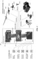
- Figure 1 shows an exemplary embodiment of a universal control architecture 100 used in controlling one or more unmanned systems 110.
- the unmanned systems 110 can be controlled by a common control device 120.
- common control device 120 which can be, for example, a single handheld controller, can have a video display 122 (and/or audio output, not shown, in the form of speakers, output jacks, wireless connections, etc.).
- the common control device 120 can be configured to control one or more unmanned systems 110, including one or more ground-based unmanned systems (e.g., UGVs, small unmanned ground vehicles (sUGVs), sUGVs with explosive ordinance disposal [EOD] capabilities, etc.), one or more aerial-based unmanned systems (e.g., UAS, small UAS, nano UAS, etc.), and/or one or more maritime-based unmanned systems (not shown).
- ground-based unmanned systems e.g., UGVs, small unmanned ground vehicles (sUGVs), sUGVs with explosive ordinance disposal [EOD] capabilities, etc.
- aerial-based unmanned systems e.g., UAS, small UAS, nano UAS, etc.
- maritime-based unmanned systems not shown.
- exemplary embodiments of the disclosed universal control architecture can be agnostic to the communication protocol (e.g., ROS, MAVLink, JAUS, a proprietary communication protocol, etc.) used by and/or configured to run on an unmanned system.
- the communication protocol e.g., ROS, MAVLink, JAUS, a proprietary communication protocol, etc.
- the common control device 120 can be game-type controller, a mobile phone, a tablet computer, another type of handheld device, or another type of portable communication device that can comprise one or more application programs and/or plugins configured to run an ecosystem (e.g., a network of actors, services, capabilities, information flows, and supporting architecture corresponding to unmanned system operations).
- an ecosystem e.g., a network of actors, services, capabilities, information flows, and supporting architecture corresponding to unmanned system operations.
- the common user device 120 can be a handheld communication device running Kinesis TM software from Tomahawk Robotics to provide a secure common control system for multiple unmanned systems.
- the common control device 120 can be connected to an extension module 130 (e.g., a Kinesis Expansion Module (KxM) module from Tomahawk Robotics).
- KxM Kinesis Expansion Module
- the extension module 130 can also run application programs and/or plugins and can be regarded as an extension of the ecosystem controlled by the common control device 120.
- the extension module 130 can be configured to receive, distribute, and process large amounts of data. This data can be received or distributed via local digital connections (USB) to hosted peripherals or logically over a larger IP network using connected communications equipment (cellular radios, closed network radio, internet connection, etc.).
- USB local digital connections
- the extension module 130 allows for edge processing, which helps with data privacy and security, reduce system costs by not having a centralized server (e.g., a cloud server), and/or reduce latency and/or bandwidth issues by having the data processed (e.g., enhanced filtering, object detection, change detection, etc.) and controlled (e.g., further compressed, for example digital video, for larger network distribution, down-sampled, transcoded for efficient network traversal, etc.) at the deployment site.
- the data processed e.g., enhanced filtering, object detection, change detection, etc.
- controlled e.g., further compressed, for example digital video, for larger network distribution, down-sampled, transcoded for efficient network traversal, etc
- the extension module 130 can be configured to facilitate one or more AI capabilities (e.g., mission planning capability, capability to provide indications and warnings, enhanced autonomy capability, aided target detection capability, training and simulation capability, and/or other AI capabilities).
- AI capabilities e.g., mission planning capability, capability to provide indications and warnings, enhanced autonomy capability, aided target detection capability, training and simulation capability, and/or other AI capabilities.
- the universal control architecture can include other devices that can provide situational awareness to persons (e.g., soldiers) and/or equipment on the network.
- a user in the system can carry (e.g., mounted to his/her chest) an end user device (e.g., a handheld communication device such as an Android phone, other mobile device, or other type of communication device, etc.) for situational awareness.
- the end user device 125 can include an application and/or plug-in that provides situational awareness to the user and/or to other persons/equipment on the network.
- Exemplary embodiments of the universal command architecture 100 can be used on a variety of scenarios ranging from leisure applications, commercial applications, industrial applications, search and rescue applications, military applications, etc.
- Figure 2 shows an exemplary defense-related scenario 200 which uses an exemplary embodiment of the universal command architecture.
- squads of soldiers located in one or more locations in urban area 230 have deployed multiple unmanned systems 210.
- the unmanned systems 210 can be battery-operated as is the case in scenario 200, but in other scenarios, the unmanned systems can be powered by other sources (e.g., solar, gasoline-based, natural gas, etc.).
- the unmanned systems 210 can be deployed for the purposes of detecting and removing improvised explosive devices (IEDs) in an urban area 230.
- IEDs improvised explosive devices
- unmanned aerial vehicle (UAV) 210a and/or unmanned ground vehicle (UGV) 210b can be controlled using a common control device 220, which can be similar to the common control device 120 discussed above.
- UAV unmanned aerial vehicle
- UUV unmanned ground vehicle
- Embodiments of the present disclosure are not limited to controlling two unmanned systems, however. In other scenarios, more than two or less than two unmanned systems can be deployed, and the unmanned systems can be any combination of different types or same types of unmanned systems.
- the common user device 220 can include applications and/or plugins that allow the operator to control more than one unmanned system (e.g., either the same and/or different types of unmanned systems) using the same common control device 220.
- the end user device(s) 255 can be used by other soldiers within squad 240 and/or other squads 245,247 to potentially facilitate other functions for scenario 200.
- squad 245 can correspond to the ground force command position that coordinates all the operations in scenario 200
- squad 247 can correspond to an assault element and clearing squad that engages the enemy and/or clears improvised explosive devices (IEDs) that have been located by UAV 210a and UGV 210b.
- the common control device 220 can control the unmanned systems 21 0a, 210b using respective control protocols 250a and 250b.
- the common control device 220 can communicate with one or more end user devices 255 in squads 245, and/or 247 using control protocols 255a and/or 255b.
- an end user device 255 can relay information to one or more other end user devices 255 rather than communicate directly with the common control device 220.
- end user device 255 for squad 247 communicates with common control device 220 via the end user device 255 for squad 245, but, in other scenarios, the end user device 255 for squad 247 can communicate directly with common control device 220.
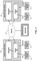
- the disclosed universal control architecture can comprise of a set of hardware and/or software components to control/monitor one or more unmanned systems using a common control device.
- the software components can be distributed across physically separate hardware devices, which can include the common control device, the extended module, the end user device, the unmanned systems, and/or other hardware devices. That is, in some embodiments, individual software components can reside on one or more physically separate hardware devices.
- the set of hardware and software components can be reachable on a common network. The network can be ad-hoc, for example, without the need for a central server.
- exemplary embodiments of the universal control architecture can be functionally operative even if some of its components are unavailable or unreliable.
- the network which can be commonly accessible by the hardware devices, can comprise one or more transport layers and physical layers which allows for low-latency connectivity of different types of robotic systems and/or sensors (e.g., body cams, wearable devices, unattended sensors, etc.).
- the embodiments disclosed herein are agnostic in that the different types of robotic systems and/or sensors do not necessarily need to communicate using the same communication protocol.
- control information is abstracted and generalized into common control data streams to allow independent control of each vehicular platform subsystem and/or payload platform subsystem regardless of the application type (aerial-based, ground-based, maritime-based, etc.).
- the control information e.g., control inputs
- control schemes and autonomy algorithms based on the common control data stream can be applied to a broad range of specific unmanned systems (e.g., broad range of vehicle platforms and/or payload platforms) with minimal or no additional engineering or mental effort.
- Figure 3 illustrates a simplified function block diagram of an exemplary embodiment of a universal control architecture that shows the control data flow between a common control device to one or more device-specific heterogeneous unmanned systems via one or more function blocks representing intermediary abstractions and/or decompositions (e.g., non-device specific function blocks). That is, in some embodiments, common control of multiple unmanned systems (including unmanned systems of different application platforms) can be based on decomposing and/or abstracting certain portions of the control data (and/or the status data) so as to be device independent with respect to the unmanned systems and/or the common control device. For example, functional subsystems that are common to more than one unmanned system can be abstracted into generic models to facilitate common control of the unmanned systems.
- a functional subsystem can be regarded as independent-controllable portion of an unmanned system such as, for example, the vehicle portion and/or the payload portion.
- the universal command device abstracts the function subsystems into generic vehicle models or behaviors corresponding to the motion of the unmanned vehicle, generic payload models or behaviors corresponding to the motions of a payload on the unmanned vehicle, and/or generic audio/visual (A/V) format models or behaviors corresponding to information from sensors on the unmanned vehicle and/or payload portions.
- Examples of a functional subsystem can include a "hovering vehicle” portion (including associated control and/or status information) of respective drones, a “skid-steer vehicle” portion (including associated control and/or status information) of certain ground robots, a “gimbal payload” portion for angular positioning (including control and/or status information), an "n-DOF manipulator payload” portion (e.g., 6-DOF, etc.) for robotic arms comprising, for example, serial revolute joints, etc.
- Functional subsystems can also include A/V format models for sensors located on the vehicle portion and/or payload portion of certain unmanned systems.
- the function block diagram 300 illustrates the control data flow for controlling one or more unmanned systems based on inputs from a common control device by using generic functional subsystem models associated with the unmanned systems.
- the unmanned systems being controlled include a drone 360a, a wall-mounted PTZ camera 360b, and a ground robot 360c.
- a common control device can additionally or alternately operate any number and combinations of aerial-based, ground-based, and/or maritime-based unmanned systems.
- the drone 360a can include a hover vehicle subsystem and a gimbal payload subsystem
- the wall-mounted PZT camera 360b can include a gimbal payload subsystem
- the ground robot 360c can include a skid steer vehicle subsystem, a gimbal payload subsystem and a manipulator payload subsystem.
- each of unmanned subsystems can be controlled by a common control device.
- the input mapping function block 320 then creates instances of manual and/or autonomous input functions (not shown in Figure 3 ) for each motion in an unmanned system that is being controlled (e.g., one or more payload subsystem motions and/or one or more vehicle subsystem motions).
- An unmanned system can be controlled based on manual teleoperation, based on autonomous operation, or based on a combination of manual teleoperation and autonomous operation.
- interpretation between input mapping block 320 and attached vehicle and payload models is one where the operator wants to operate a camera gimbal payload attached to a hovering vehicle as if it was capable of a continuous pan (movement along the horizontal axis of the camera when looking at the horizon) behavior which some expensive, highly capable aerial vehicles include and which behavior the operator is accustomed to having at their disposal.
- Lighter weight, lower cost hovering vehicles typically only have a pitch controllable axis as part of the camera gimbal payload and therefore not capable of continuous panning the camera feed without excitation of the host vehicle.
- interpretations within the universal control architecture are then used to couple motion between the hovering vehicle and gimbal simultaneously (whether stationary hovering or in motion) to achieve the desired behavior the operator expected, seamlessly and without cognition by the operator, thus achieving a common behavior regardless of gimbal degrees of freedom.
- Another example is when for instance, the operator is manually teleoperating a hovering vehicle system through an attached gimbal payload that can both pan and pitch (able to move in both the horizontal and vertical axis of the camera system).
- the camera is pointing forward, and the horizontal axis of the camera gimbal and hovering vehicles are aligned, operation through the camera feed is very intuitive because a forward command moves the camera and vehicle along the traditional transversal control axis for going forward.
- the mapping function of the universal control architecture can recognize the position of the camera payload (off to the side) with respect to the principal transversal control axis and re-map the control to the vehicle to allow the vehicle to always flight straight from the perspective of the camera and not the along the original transversal axis aligned with the vehicle.
- the end result from this mapping function example is that with the camera payload pointing to the side of the vehicle, and the user commanding forward along what was the original transversal axis, the actual vehicle will roll instead of pitch in order to move the vehicle in the direction the camera is pointing without any input or change from the operator from his original intent, making the system very intuitive to operate.
- the device-independent generic behavioral models allow the user to have a common control experience for each motion type (e.g., flying, driving (tracked and/or wheeled vehicles), hovering, tracking, positioning, manipulating, etc.) even if the unmanned systems are different.
- each motion type e.g., flying, driving (tracked and/or wheeled vehicles), hovering, tracking, positioning, manipulating, etc.
- the common control data stream 310 can be input to the teleoperation behavior function block(s) 330 and/or the autonomous behavior function block(s) 340 which can provide a generic behavior or model of a motion (payload subsystem motion and/or vehicle subsystem motion) to be controlled.
- a model may be referred to as a movement control model.
- the generic behaviors or models for autonomous function blocks can be based on a preprogrammed (e.g., predetermined) software/hardware function rather than from received inputs (indicated by dashed arrows as part of Figure 3 block 340). Instances of the teleoperation function blocks can be created based on the vehicle and/or payload subsystem being controlled manually.
- teleoperation behavior function block 330a can correspond to a generic hovering vehicle model for manual hover motion control
- teleoperation function block 330b can correspond to a generic skid steer vehicle model for manual track motion control
- teleoperation function block 330c can correspond to a generic gimbal payload model for manual control of positioning motion.
- instances of the autonomous function blocks can be created based on the vehicle and/or payload subsystem being controlled autonomously.
- autonomous function block 340a can correspond to generic gimbal payload model for autonomous control of gimbal positioning/aligning motion
- autonomous function block 340b can correspond to a generic manipulator payload model (e.g., controlling an arm motion) for autonomous control of a robot arm motion on the ground vehicle 360c.
- Other instances of teleoperation and/or autonomous function blocks can be added based on the vehicle and/or payload subsystems that are being controlled by the common control device.
- An example of manual control operation would be a human operator providing proportional teleoperation commands from the control device to the locomotion capability of ground robot 360c through the skid steer platform vehicle model and subsequent platform conversion block 350c.
- An example of the autonomous control operation would be drone 360a automatically following and keeping in view ground robot 360c relative to drone 360as camera field of view based on state (altitude, location, camera gimbal, etc.) and video data distributed to the software application that is running within the universal control architecture (whether on common control device, expansion module or within the addressable network).
- This software provides the automated commands to the required vehicle and payload models, blocks 340 and 330 to achieve the programmed behavior.
- the generic models 330, 340 are configured to receive a common data stream 310, extract the relevant motion control information and/or other control information, and output generic motion control information and/or other control information to the corresponding platform conversion function blocks 350, which converts the generic device-independent control data to device-dependent control data specific to the unmanned system and/or subsystem being controlled.
- Each unique make and model of controlled subsystem will require a unique implementation of such conversion, as this is the interface between the abstraction of a subsystem to the specific subsystem being controlled.
- generic hovering vehicle model 330a can receive the common control data stream 310 and extract the control data relevant to controlling a hovering vehicle (e.g., extracting the linear and/or angular velocity control data).
- the generic hover vehicle model 330a then converts the extracted common control data to generic control data (e.g., generic linear and/or angular velocity control data) corresponding to a generic hovering vehicle operation (e.g., device independent control data).
- the generic control data can be output to drone platform conversion function block 350a.
- the drone platform conversion function block 350a then converts the generic control data to hovering motion control data that is specific (e.g., device dependent) to the drone platform being controlled.
- the specific hovering motion control data can include linear and/or angular velocity data.
- drone platform conversion function block 350a can convert the generic done motion commands to platform-specific attributes that can include applying constraints or limits on the generic motion control, such as, for example, control rate gains, rate limits, maximum operational altitude and/or velocity limits, etc.
- the generic hovering motion control data can then be transmitted to the drone 360a.
- platform conversion function block 350 can translate the generic motion control data to the platform-specific attributes of the unmanned system being controlled, the generic behavior models 330, 340 can be the same for a variety of platforms (e.g., vehicle platforms and/or payload platforms).
- the same generic hovering vehicle model 330a can be used regardless of whether the hover subsystem belongs to UAS, sUAS, a nUAS, or some other unmanned drone system. This means that, from the user's point of view, a common control experience can be provided to the user regardless of the unmanned vehicle platform being controlled.
- gimbal platform conversion function block 350b can convert the generic gimbal payload motion information from the generic gimbal payload models 330c or 340a to gimbal-specific positioning motion information (e.g., motion information for gimbals on UAVs, UGVs, etc.) for drone 360a, PZT camera 360b, and ground robot 360c; skid steer platform conversion block 350c can convert the generic skid steer motion information from the generic skid steer vehicle model 330b to specific skid steer vehicle motion information (e.g., vehicle motion information for UGV, sUGV, sUGV/EOD, etc.) for ground robot 360c; and manipulator platform conversion block 350d can convert the generic manipulator payload motion information from the generic manipulator payload model 330d to specific manipulator motion information (e.g., manipulator motion information for n-DOF manipulators on UAVs, UGVs, etc.) for ground robot 360
- the common control device after the conversion to platform-specific motion control data, can translate the converted motion data into the communication protocol used by the unmanned system being controlled.
- protocol conversion function blocks (not shown in Figure 3 ) can convert the output of the platform conversion functional block 350 to the proper protocol (e.g., MAVLink, JAUS, ROS, a proprietary protocol, or some other protocol) that is used by the corresponding unmanned system 360 being controlled.
- the common control device after conversion to the proper protocol, can transmit (e.g., via either a wired and/or wireless system) the motion control data to the appropriate unmanned system 360.
- the unmanned drone system 360a can have a vehicle subsystem that controls the flight operations of the drone, as well as a payload subsystem that includes a gimbal that controls an angular positioning of the camera along, for example, three axes.
- the control inputs by the user e.g., using the common control device
- to manually operate the motion of the vehicle portion of the drone will be interpreted as teleoperation "hover behavior" (e.g., by the input mapping function block 320) and mapped to a corresponding generic hover vehicle model (e.g., hover vehicle model 340a) that claims the vehicle subsystem and thus the flight operations of the unmanned done system 360a.
- control inputs and/or device/software inputs for a preprogrammed (or predetermined) autonomous mission can be interpreted (e.g., by the input mapping function block 320) as an autonomous "visually track target behavior" and mapped to an autonomous generic gimbal payload model (e.g., gimbal payload model 340a) that claims the payload subsystem and thus the gimbal mechanism operation of the unmanned drone system 360a to visually track the target.
- an autonomous generic gimbal payload model e.g., gimbal payload model 340a
- a simple ground robot e.g., ground robot 360d
- a high degree-of-freedom robot manipulator might have a "manipulate" behavior can map end-effector velocities in cartesian task space to individual angular velocities for each joint.
- both control cases can be mapped to a "general" 6-DOF (three linear and three angular) movement principle, allowing each unmanned system to be operated in a common manner.
- the user pushes forward on the yoke to tilt the aircraft forward, right to roll the aircraft right, etc. It is as if the user is holding a model of the aircraft in their hand and moving the model in the way a real aircraft should move.
- the user's intent is translated to the aircraft's movement.
- the "translation" feature (e.g., as implemented by the input mapping function block 320) is particularly beneficial as the complexity of the unmanned system and/or of the robotic subsystems grows, especially if the systems are interdependent. For example, a robotic high degree of freedom manipulator mechanism can be very tedious to control by manually controlling the velocities of each joint.
- the control system can abstract away the manipulator mechanism and allow direct command of the angular and translational velocities of the end effector of the manipulator arm, the complexity of the manipulator mechanism is mostly irrelevant.
- the operator dictates whether the universal control architecture is in autonomous or manual operation mode via input on the common control device.
- the described architecture in block 300 of Figure 3 allows for multiple unmanned systems to be assigned autonomous tasks when the operator is manually operating a separate unmanned system.
- the operator can manually control a grouping of multiple unmanned systems that are performing autonomous behaviors amongst each other. For example, multiple iterations of drone block 360a exist on the network and they are selected as a group of nUAS.
- the input mapping function block 320 can include a perspective function that takes into account which reference frame is being displayed on the common control device (e.g., a reference frame from the viewpoint of the unmanned system, a reference frame of the unmanned system being controlled but separate from the unmanned system, etc.) and the displayed reference frame is aligned with a reference frame of the common control device.
- the disclosed universal command architecture enables the operator to control unmanned systems from whatever perspective the operator is currently viewing the system. If the operator is looking at a video feed from a camera mounted directly on a vehicle facing forward, the control inputs can be interpreted by the input mapping function block 320 as if the operator is "riding" in the vehicle.
- "forward” direction can mean to move "into" the screen that the operator is viewing because the screen's reference frame and perspective and the vehicle's reference frame and perspective are aligned (e.g., the same).
- the operator's inputs will be rotated such that "forward” means into the screen (which no longer means “forward” for the vehicle), and "left” means to the left side of the screen.
- the rotation between the screen's perspective and the operator's perspective changes over time as the two systems move relative to each other.
- perspectives with respect to one frame may need to be mapped into another frame, for accurate translation.
- Perspective translation is achieved by applying the inverse of the coordinate frame rotation from the sensor capturing the user's presented perspective and the frame of the vehicle itself.
- the rotation between the two is zero, meaning no translation is required.
- the inverse of that rotation is applied to the control inputs to maintain alignment between the user's control intent and the vehicle's interpretation of the command.
- the disclosed architecture provides a data stream that has attitude and location information for one or more unmanned systems, sensors, and devices on the network
- the disclosed architecture facilitates calculation of the transformation between any two attitude frames.
- the disclosed architecture is also aware of sensors' lens characteristics, and therefore allows precise calculation of relative positions of objects in a sensor frame.
- this allows control of a controllable entity on the network from the perspective of another entity. Since the disclosed system has awareness of the location and rotation of all entities in the global frame, the translation of control inputs from any one frame into another is calculated simply by applying the inverse rotation between the frames as described above.
- the exemplary behavior models correspond to controlling a motion of an unmanned system with the control flow going from the common control device (and/or another device on network) to the unmanned system.
- status information e.g., linear and/or angular velocities
- behaviors can also apply to non-motion related subsystems of unmanned systems such as, for example, subsystems related to monitoring and/or transmitting telemetry information (e.g., digital video, status information, etc.).
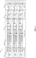
- Figure 4 shows a multi-layered control representation of a universal control architecture that includes several stages of translations of control data, status data, and/or audio/video data.
- function blocks 420, 430, 440, 450, and 455 correspond to various intermediate transformation stages that includes an abstraction layer, protocol translation layer, and network transport layer for processing the control, status, and/or audio/video.
- Each layer serves abstracts an aspect of the controlled system or controller such that both are effective independent from the particular implementation of the other.
- the Abstraction Layer comprised of blocks 430, 440, and 450 abstract the user's control intent for a generic subsystem, and then maps the generic subsystem to a specific platform model.
- the Protocol layer (455) abstracts the physical implementation of the controlled system from the platform model.
- the network layer (460) abstracts the physical connection of the robot to the controller.
- Figure 4 shows a more detailed view of the functions discussed above with respect to Figure 3 .
- Figure 3 provides an overview of the control data flow from the common control device to the unmanned systems
- Figure 4 shows an overview of the control data flow from the common control device to the unmanned systems (and vice-versa depending in the type of control system) and the status and/or A/V data flow from the unmanned systems to the common control device (and vice-versa depending in the type of control system).
- the status data can include data corresponding to location information, position information, attitude information, and/or other status information
- the A/V data can include video and/or audio from the unmanned systems (e.g., in digital format).
- the translations can be model-generated transformations of the control, status, and/or A/V data that are transmitted between a common control device and one or more unmanned systems.
- Figure 4 shows the A/V data as being one-directional from the unmanned systems to the common control device, in some embodiments, the A/V data can also be transmitted from the common control device (and/or another device on the network) to the unmanned device (e.g., the unmanned device can have speakers that can broadcast a warning from the user to persons in the vicinity of the unmanned device).
- I/O function block 420 shows the transformations on the control inputs corresponding to teleoperation (e.g., inputs provided by a common control device 120, 220) and/or automation (e.g., inputs provided by a software and/or device functions).
- I/O function block 420 shows input mapping functions similar to those of input mapping function block 320 of Figure 3 but, along with input mapping functions, the I/O function block 420 also includes output mapping functions that map status and/or A/V data from the unmanned systems (and/or another device on the network) to an A/V component used by the user (e.g., a display and/or audio jacks/speakers on the common control device).
- I/O function block 420 includes two I/O subblocks 420a and 420c corresponding to instances where the common control device (e.g., common control device 120 and/or 220) and/or another device has interpreted inputs as teleoperations (e.g., manual control) and one instance I/O subblock 420b corresponding to an instance where the inputs are interpreted as an autonomous operation.
- the common control device e.g., common control device 120 and/or 220
- another device has interpreted inputs as teleoperations (e.g., manual control)
- one instance I/O subblock 420b corresponding to an instance where the inputs are interpreted as an autonomous operation.
- there can be any number of teleoperation function blocks and autonomous function blocks depending on the number unmanned systems being controlled and the mode of operation for each unmanned system or functional subsystem.
- the abstraction layer interprets the control intent from the user and converts it to a control command for an abstract agent type (vehicle, payload, etc.).
- control intent is interpreted based on the user's selected control mode for the agent type. For example, the user may choose to drive a robot using its Skid-steer mode, then switch control modes to Manipulate to route user input to the onboard manipulator arm.
- Control modes are not limited to single subsystems, as modes may control two or more subsystems to perform coordinated motion. For example, if a robot has a manipulator arm that is not capable of rotating horizontally, the Manipulate control mode may interpret input horizontal rotation to command rotation of the entire robot, while interpreting other axes of input to command the joints of the robot arm.
- I/O subblock 420a can provide manual control of an unmanned drone system 460a, including manual control of both the vehicle subsystem and the payload subsystem.
- I/O subblock 420c can provide manual control of an unmanned water vehicle system 460c, including manual control of both the vehicle subsystem and the payload subsystem.
- the operator can selectively operate the drone system 460a or the water vehicle system 460c using a common control device.
- I/O subblock 420b can provide autonomous control of tracked ground vehicle system 460b, including autonomous control of both the vehicle subsystem and the payload subsystem.
- an exemplary scenario can be that, while the user manually operates the drone 460a the tracked ground vehicle 460b has a predetermined autonomous function to automatically follow the drone's position and/or an area where the drone's camera is manually pointing to.
- the vehicle and payload subsystems in each of the unmanned vehicle can have any combination of teleoperation or autonomous control, depending on the scenario.
- the control of one or more vehicle subsystems in each unmanned system can be manual while the control of one or more payload subsystems can be autonomous.
- the inputs in the respective I/O function blocks 420a-c are machine-translated into generalized, uniform set of data such as, for example, a set of state variables.
- the input data e.g., set of state variables
- the input data can then be interpreted by behavior function blocks 430, 440 and modeled as generic behaviors of subsystems of unmanned systems (e.g., flying, driving (tracked and/or wheeled vehicles), hovering, tracking, positioning, manipulating, etc.).
- the behavioral function blocks 430, 440 convert the generalized common control data into generic vehicle and/or payload motion control data for the specific desired motion.
- the outputs (e.g., motion control data) of the I/O subblocks 420a, 420b, and 426 can be transmitted to a common I/O data stream 410 that can be input to teleoperation behavior function blocks 430 (e.g., function blocks 430a-f) and/or autonomous behavior function block 440 (e.g., function blocks 440a-c), and the outputs from the behavior function blocks 430, 440 can be transmitted to the common I/O data stream 410 that can be input to the I/O function blocks 420.
- Figure 4 shows how individual data streams are transmitted between the I/O function blocks 420 and the behavior function blocks 430, 440.
- one or more separate data streams can be used to between the I/O function blocks 420 and the respective behavior function blocks 430, 440.
- a set of state variables [v, ⁇ ⁇ v ] can represent the linear vehicle velocities and/or angular vehicle velocities, respectively, of the vehicle subsystem.
- the vehicle velocities can represent, for example, 6-DOF and include control and/or status information.
- Another set of state variables [p, ⁇ p , ⁇ ] can represent the linear payload velocities, angular payload velocities, and/or auxiliary control functions (e.g., functions controlling non-moving equipment and/or other equipment on the unmanned system), respectively, of the payload subsystem.
- the vehicle velocities can represent, for example, 6-DOF and include control and/or status information.
- behavioral function block 430a can be configured as a generic hovering vehicle model to provide motion control data for the vehicle subsystem of drone system 460a.
- Behavioral function block 430a can receive a set of state variables [v ⁇ c , ⁇ vc ] (where the subscript c represents common data) from common I/O data stream 410.
- the behavioral function block 430a converts the common set of state variables [v ⁇ c , ⁇ vc ] to a generic hover motion control data.
- the platform-specific payload velocity state variables [ ⁇ s , ⁇ ps , ⁇ s ] and/or auxiliary control data are converted to the proper protocol by protocol conversion function block 455a and transmitted of the unmanned drone system 460a for control of the gimbal payload subsystem.
- the platform conversion function block 450a and the protocol conversion function block 455a are common to both the vehicle and payload control scheme for the unmanned done system 460a.
- one or both the platform conversion function block 450a and the protocol conversion function block 455a can be separate function blocks in other embodiments.
- one or more behavioral function models can be combined with another behavioral function model, depending on a desired control scheme.
- a desired control scheme For example, an unmanned system in which the vehicle and payload subsystems are interrelated can have a behavioral function model that takes into account the interrelated motions of these subsystems.
- Those skilled in the art will recognize that the state variable conversions for unmanned systems 460b and 460c are similar and thus, for brevity, a detailed discussion is omitted.
- protocol conversion block 455 can convert status and/or A/V information in the protocol-specific format to a platform-specific format (e.g., when state variables are used, into state variables [v ⁇ s , ⁇ vs ] and/or state variables [ ⁇ s , ⁇ ps , ⁇ s ]), that can be read by the platform conversion function block 450, which then converts the status and/or A/V information in the platform-specific format into a generic format (e.g., when state variables are used, from state variables [v ⁇ s , ⁇ vs ] and/or state variables [ ⁇ s , ⁇ ps , ⁇ s ] into respective state variables [v ⁇ g , ⁇ vg ] and/or state variables [ ⁇ g , ⁇ pg , ⁇ g ]).
- a platform-specific format e.g., when state variables are used, into state variables [v ⁇ s , ⁇ vs ] and/
- Any computer program may be stored on an article of manufacture, such as a storage medium (e.g., CD-ROM, hard disk, or magnetic diskette) or device (e.g., computer peripheral), that is readable by a general or special purpose programmable computer for configuring and operating the computer when the storage medium or device is read by the computer to perform the functions of the embodiments.
- a storage medium e.g., CD-ROM, hard disk, or magnetic diskette
- device e.g., computer peripheral
- the embodiments, or portions thereof may also be implemented as a machine-readable storage medium, configured with a computer program, where, upon execution, instructions in the computer program cause a machine to operate to perform the functions of the embodiments described above.
- the descriptions are applicable in any computing or processing environment.
- the embodiments, or portions thereof may be implemented in hardware, software, or a combination of the two.
- the embodiments, or portions thereof may be implemented using circuitry, such as one or more of programmable logic (e.g., an ASIC), logic gates, a processor, and a memory.
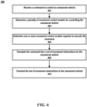
- FIG. 6 is a flowchart of operations for using the universal control architecture to control one or more unmanned vehicles in accordance with an embodiment of the present disclosure.
- the operations discussed in connection to Figure 6 may be performed on operator control device 520.
- operator control device 520 receives a command to control an unmanned vehicle.
- Operator control device 520 may receive the command from an autonomous command user input interface (e.g., hover) or may receive the command from a manual input user interface (e.g., from a joystick type of a device).
- an autonomous command user input interface e.g., hover
- a manual input user interface e.g., from a joystick type of a device.
- operator control device 520 determines one or more movement control models required to execute the command.
- operator control device 520 may process the command and determine which movement control model (or models) are required to execute the command.
- the command may be an autonomous mode command that instructs an unmanned vehicle to hover and capture video of a particular position or location.
- Operator control device 520 may determine that the unmanned vehicle should fly to the position or location, then hover at that location while capturing video.
- Operator control device 520 may retrieve the flying movement control model, the hover movement control model and the gimbal movement control model associated with the unmanned vehicle.
- Operator control device 520 may then input the coordinates of the position and location into the flying movement control model to instruct the unmanned vehicle to fly to the particular location.
- operator control device 520 may retrieve a driving movement control model and input the coordinates of the position into that model.
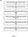
- operator control device 520 transmits an identification request to the unmanned vehicle.
- operation control device 520 may broadcast a wireless signal requesting identification information.
- the signal may be received by the transceiver on the unmanned vehicle.
- the detection and identification request may be performed using a wired connection.
- operation control device 520 may be connected to the unmanned vehicle using a wire and the signals may be transmitted back and forth over that wire.
- the identification request may be formatted according to the model of the unmanned vehicle, which may be detected when the unmanned vehicle is detected.
- operator control device 520 receives indications of movement types associated with the unmanned vehicle and additional vehicle information.
- Each movement type may be associated with one or more movement commands supported by the unmanned vehicle.
- the operator control device 520 may receive a data structure that includes a plurality of movement types supported by the unmanned vehicle.
- the data structure may be in a form of a data file that operator control device 520 is able to process.
- the unmanned vehicle is an unmanned aerial vehicle
- the unmanned vehicle may support hovering commands, flying commands, etc.
- the data structure may include flying and hovering commands supported by the unmanned vehicle.
- movement commands may include underwater operating commands, above-water operating commands, etc. Those movement commands may be part of the data structure received by operator control device 520.
- operator control device 520 determines one or more movement control models for moving the unmanned vehicle. Each movement control model translates operator commands into movement instructions for the unmanned vehicle. In some embodiments, operator control device 520 may perform the following operations when determining the one or more movement control models. As described above, operation control device 520 may receive, from the unmanned vehicle, a plurality of supported movement commands and may match the plurality of supported movement commands with the one or more movement control models. Operation control device 520 may store a listing of movement commands and corresponding control model(s) that support those commands.
- Operation control device 520 may test the assigned movement control models.
- operation control device 520 may generate a plurality of test commands for the unmanned vehicle.
- Each test command of the plurality of test commands may test a particular movement control model or a payload movement control model.
- operation control device 520 may generate a command the instructs the unmanned aerial vehicle to hover at particular coordinates.
- operation control device 520 may instruct an unmanned ground vehicle to drive to particular coordinates.
- the test may also include testing the payload device.
- a test command may instruct a gimbal to rotate a certain number of degrees.
- Operation control device 520 may determine, based on a payload movement control model, expected orientation information associated with the payload device. For example, operation control device 520 may input the test command into the appropriate model and receive back an expected orientation of the payload device. Operation control device 520 may then determine, based on the expected orientation information and the payload orientation information from the unmanned vehicle, whether the set of instructions moved the payload device into an expected orientation.
- the instructions when executed by the one or more processors, further cause the one or more processors to: determine that a first movement control model matches a first portion of the first plurality of supported movement commands and a second movement control model matches a second portion of the first plurality of supported movement commands; and generate a new movement control model comprising a first application programming interface for the first plurality of supported movement commands and a second application programming interface for the second portion of the first plurality of supported movement commands.
- a method comprising: detecting an unmanned vehicle within a vicinity of a controller; transmitting an identification request to the unmanned vehicle; receiving, in response to the identification request, indications of movement types associated with the unmanned vehicle, wherein each movement type is associated with a movement command supported by the unmanned vehicle; determining, based on the indications of movement types associated with the unmanned vehicle, one or more movement control models for moving the unmanned vehicle, wherein each movement control model translates operator commands or automation inputs into movement instructions for the unmanned vehicle; assigning the one or more movement control models to the unmanned vehicle; and controlling the unmanned vehicle using the one or more movement control models.
- each test command of the plurality of test commands tests a movement control model
- translating, using the one or more movement control models, the plurality of test commands into a plurality of sets of movement instructions for the unmanned vehicle formatting the plurality of sets of movement instructions according to a communication protocol associated with the unmanned vehicle; and transmitting the plurality of sets of movement instructions formatted according to the communication protocol to the unmanned vehicle.
- determining the one or more movement control models further comprises: receiving, from the unmanned vehicle, a plurality of supported movement commands; matching the plurality of supported movement commands with the one or more movement control models; and assigning, to an unmanned vehicle object, the one or more movement control models that match the plurality of supported movement commands.
- a non-transitory, computer-readable medium storing instructions for adding unmanned vehicles to a common command and control architecture, the instructions when executed by one or more processors, cause the one or more processors to perform operations comprising: detecting an unmanned vehicle within a vicinity of a controller; transmitting an identification request to the unmanned vehicle; receiving, in response to the identification request, indications of movement types associated with the unmanned vehicle, wherein each movement type is associated with a movement command supported by the unmanned vehicle; determining, based on the indications of movement types associated with the unmanned vehicle, one or more movement control models for moving the unmanned vehicle, wherein each movement control model translates operator commands into movement instructions for the unmanned vehicle; assigning the one or more movement control models to the unmanned vehicle; and controlling the unmanned vehicle using the one or more movement control models.
- the instructions further cause the one or more processors to perform operations comprising: receiving in response to the identification request, payload types associated with the unmanned vehicle and a communication protocol associated with the unmanned vehicle; determining, based on the payload types, a payload movement control model for moving a payload device mounted on the unmanned vehicle, wherein the payload movement control model translates payload movement commands into payload movement instructions for the payload device mounted onto the unmanned vehicle; assigning the payload movement control model to the unmanned vehicle; and controlling the payload device mounted on the unmanned vehicle using the payload movement control model.
- the instructions further cause the one or more processors to perform operations comprising: generating a plurality of test commands for the unmanned vehicle, wherein each test command of the plurality of test commands tests a movement control model; translating, using the one or more movement control models, the plurality of test commands into a plurality of sets of movement instructions for the unmanned vehicle; formatting the plurality of sets of movement instructions according to a communication protocol associated with the unmanned vehicle; and transmitting the plurality of sets of movement instructions formatted according to the communication protocol to the unmanned vehicle.
- the instructions further cause the one or more processors to perform operations comprising: receiving, from the unmanned vehicle, position information resulting from execution of the plurality of sets of movement instructions; determining, based on the one or more movement control models, expected position information associated with the unmanned vehicle; and determining, based on the expected position information and the position information from the unmanned vehicle, whether the plurality of sets of instructions moved the unmanned vehicle into an expected position.
- the instructions for determining the one or more movement control models further cause the one or more processors to perform operations comprising: receiving, from the unmanned vehicle, a plurality of supported movement commands; matching the plurality of supported movement commands with the one or more movement control models; and assigning, to an unmanned vehicle object, the one or more movement control models that match the plurality of supported movement commands.
- the instructions further cause the one or more processors to perform operations comprising: determining that a first movement control model matches a first portion of the plurality of supported movement commands and a second movement control model matches a second portion of the plurality of supported movement commands; and generating a new movement control model comprising a first application programming interface for the first portion of the plurality of supported movement commands and a second application programming interface for the second portion of the plurality of supported movement commands.
- the instructions further cause the one or more processors to perform operations comprising: receiving, from the unmanned vehicle, a plurality of supported payload commands; matching the plurality of supported payload commands with one or more payload movement control models; and assigning, to an unmanned vehicle object, the one or more payload movement control models that match the plurality of supported payload commands.
Landscapes
- Engineering & Computer Science (AREA)
- Aviation & Aerospace Engineering (AREA)
- Radar, Positioning & Navigation (AREA)
- Remote Sensing (AREA)
- Physics & Mathematics (AREA)
- General Physics & Mathematics (AREA)
- Automation & Control Theory (AREA)
- Control Of Position, Course, Altitude, Or Attitude Of Moving Bodies (AREA)
Claims (13)
- System zum Hinzufügen unbemannter Fahrzeuge zu einer gemeinsamen Befehls- und Kontrollarchitektur, das System umfassend:einen oder mehrere Prozessoren undein nichtflüchtiges computerlesbares Speichermedium, das Anweisungen speichert, die bei Ausführung durch den einen oder die mehreren Prozessoren den einen oder die mehreren Prozessoren dazu veranlassen:ein unbemanntes Fahrzeug in der Nähe einer Steuerung zu erkennen, wobei das unbemannte Fahrzeug eine Nutzlastvorrichtung umfasst,eine Identifikationsanfrage an das unbemannte Fahrzeug übermitteln,als Reaktion auf die Identifikationsanfrage Fahrzeuginformationen zu empfangen, wobei die Fahrzeuginformationen Hinweise auf Bewegungstypen umfassen, die mit dem unbemannten Fahrzeug verknüpft sind, Nutzlasttypen, die mit dem unbemannten Fahrzeug verknüpft sind, und Kommunikationsprotokolle, die mit dem unbemannten Fahrzeug verknüpft sind,zu bestimmen, basierend auf den Fahrzeuginformationen, eines oder mehrere Bewegungs-Steuerungsmodelle zum Bewegen des unbemannten Fahrzeugs, eines Nutzlastbewegungs-Steuerungsmodells zum Bewegen der Nutzlastvorrichtung, die dem unbemannten Fahrzeug zugeordnet ist, wobei jedes Bewegungs-Steuerungsmodell Befehle eines Bedieners in Bewegungsanweisungen für das unbemannte Fahrzeug oder die Nutzlastvorrichtung übersetzt,das eine oder die mehreren Bewegungs-Steuerungsmodelle, das Nutzlastbewegungs-Steuerungsmodell und das Kommunikationsprotokoll einem unbemannten Fahrzeugobjekt zuzuweisen,eine Vielzahl von Testbefehlen für das unbemannte Fahrzeug zu erzeugen, wobei jeder Testbefehl der Vielzahl von Testbefehlen ein Bewegungs-Steuerungsmodell oder ein bestimmtes Nutzlastbewegungs-Steuerungsmodell testet,unter Verwendung des einen oder der mehreren Bewegungs-Steuerungsmodelle und des Nutzlastbewegungs-Steuerungsmodells die Vielzahl von Testbefehlen in eine Vielzahl von Sätzen von Bewegungsanweisungen für das unbemannte Fahrzeug zu übersetzen,die Vielzahl von Sätzen von Bewegungsanweisungen gemäß dem Kommunikationsprotokoll, das dem unbemannten Fahrzeug zugeordnet ist, zu formatieren unddie Vielzahl von Sätzen von Bewegungsanweisungen, die gemäß dem Kommunikationsprotokoll formatiert sind, an das unbemannte Fahrzeug zu übertragen.
- System nach Anspruch 1, wobei die Anweisungen, wenn sie von dem einen oder den mehreren Prozessoren ausgeführt werden, den einen oder die mehreren Prozessoren ferner dazu veranlassen:vom unbemannten Fahrzeug Positionsinformationen zu empfangen, die sich aus der Ausführung der Vielzahl von Sätzen von Bewegungsanweisungen ergeben,basierend auf dem einen oder den mehreren Bewegungs-Steuerungsmodellen und dem Nutzlastbewegungs-Steuerungsmodell, erwartete Positionsinformationen, die dem unbemannten Fahrzeug zugeordnet sind, zu bestimmen undbasierend auf den erwarteten Positionsinformationen und den Positionsinformationen des unbemannten Fahrzeugs, zu bestimmen, ob die Vielzahl von Sätzen von Bewegungsanweisungen das unbemannte Fahrzeug in eine erwartete Position bewegt haben.
- System nach einem der Ansprüche 1 oder 2, wobei die Anweisungen zum Bestimmen, basierend auf den Fahrzeuginformationen, des einen oder der mehreren Bewegungs-Steuerungsmodelle und des Nutzlastbewegungs-Steuerungsmodells, wenn sie von dem einen oder den mehreren Prozessoren ausgeführt werden, den einen oder die mehreren Prozessoren ferner dazu veranlassen:vom unbemannten Fahrzeug eine erste Vielzahl von unterstützten Bewegungsbefehlen und eine zweite Vielzahl von unterstützten Nutzlastbefehlen zu empfangen,die erste Vielzahl von unterstützten Bewegungsbefehlen mit dem einen oder den mehreren Bewegungs-Steuerungsmodellen und die zweite Vielzahl von unterstützten Nutzlastbefehlen mit dem einen oder den mehreren Nutzlastbewegungs-Steuerungsmodellen abzugleichen unddem unbemannten Fahrzeugobjekt das eine oder die mehreren Bewegungs-Steuerungsmodelle, die mit der ersten Vielzahl von unterstützten Bewegungsbefehle übereinstimmen, und das eine oder die mehreren Nutzlastbewegungs-Steuerungsmodelle, die mit der zweiten Vielzahl von unterstützten Nutzlastbefehlen übereinstimmen, zuzuordnen.
- System nach Anspruch 3, wobei die Anweisungen, wenn sie von dem einen oder den mehreren Prozessoren ausgeführt werden, den einen oder die mehreren Prozessoren ferner dazu veranlassen:zu bestimmen, dass ein erstes Bewegungs-Steuerungsmodell mit einem ersten Teil der ersten Vielzahl von unterstützten Bewegungsbefehlen übereinstimmt und ein zweites Bewegungs-Steuerungsmodell mit einem zweiten Teil der ersten Vielzahl von unterstützten Bewegungsbefehlen übereinstimmt, undein neues Bewegungs-Steuerungsmodell zu erzeugen, das eine erste Anwendungsprogrammierschnittstelle für die erste Vielzahl von unterstützten Bewegungsbefehlen und eine zweite Anwendungsprogrammierschnittstelle für den zweiten Teil der ersten Vielzahl von unterstützten Bewegungsbefehlen umfasst.
- Verfahren, umfassend:Erkennen eines unbemannten Fahrzeugs in der Nähe einer Steuerung,Übertragen einer Identifikationsanfrage an das unbemannte Fahrzeug,Empfangen, als Reaktion auf die Identifikationsanfrage, von Hinweisen auf Bewegungsarten, die dem unbemannten Fahrzeug zugeordnet sind, wobei jede Bewegungsart einem Bewegungsbefehl zugeordnet ist, der von dem unbemannten Fahrzeug unterstützt wird,Bestimmen, basierend auf den Anzeichen zu Bewegungstypen, die mit dem unbemannten Fahrzeug verknüpft sind, eines oder mehrerer Bewegungs-Steuerungsmodelle zum Bewegen des unbemannten Fahrzeugs, wobei jedes Bewegungs-Steuerungsmodell Befehle eines Bedieners oder Automatisierungseingaben in Bewegungsanweisungen für das unbemannte Fahrzeug übersetzt,Zuweisen des einen oder der mehreren Bewegungs-Steuerungsmodelle zum unbemannten Fahrzeug undSteuern des unbemannten Fahrzeugs unter Verwendung des einen oder der mehreren Bewegungs-Steuerungsmodelle.
- Verfahren nach Anspruch 5, ferner umfassend:als Reaktion auf die Identifikationsanfrage, Empfangen von Nutzlasttypen, die dem unbemannten Fahrzeug zugeordnet sind, und eines Kommunikationsprotokolls, das dem unbemannten Fahrzeug zugeordnet ist,Bestimmen, basierend auf den Nutzlasttypen, eines Nutzlastbewegungs-Steuerungsmodells zum Bewegen oder Steuern des Zustands einer auf dem unbemannten Fahrzeug montierten Nutzlastvorrichtung, wobei das Nutzlastbewegungs-Steuerungsmodell Nutzlastbewegungsbefehle in Nutzlastbewegungsanweisungen für die Nutzlastvorrichtung übersetzt, die auf dem unbemannten Fahrzeug montiert ist,Zuordnen des Nutzlastbewegungs-Steuerungsmodells zum unbemannten Fahrzeug undSteuern der Nutzlastvorrichtung, die auf dem unbemannten Fahrzeug montiert ist, unter Verwendung des Nutzlastbewegungs-Steuerungsmodells.
- Verfahren nach einem der Ansprüche 5 oder 6, ferner umfassend:Erzeugen einer Vielzahl von Testbefehlen für das unbemannte Fahrzeug, wobei jeder Testbefehl der Vielzahl von Testbefehlen ein Bewegungs-Steuerungsmodell testet,Übersetzen, unter Verwendung des einen oder der mehreren Bewegungs-Steuerungsmodelle, der Vielzahl von Testbefehlen in eine Vielzahl von Sätzen von Bewegungsanweisungen für das unbemannte Fahrzeug,Formatieren der Vielzahl von Sätzen von Bewegungsanweisungen gemäß einem Kommunikationsprotokoll, das dem unbemannten Fahrzeug zugeordnet ist, undÜbertragen der Vielzahl von Sätzen von Bewegungsanweisungen, die gemäß dem Kommunikationsprotokoll formatiert wurden, an das unbemannte Fahrzeug.
- Verfahren nach Anspruch 7, ferner umfassend:Empfangen, vom unbemannten Fahrzeug, von Positionsinformationen, die sich aus der Ausführung der Vielzahl von Sätzen von Bewegungsanweisungen ergeben,Bestimmen, basierend auf dem einen oder den mehreren Bewegungs-Steuerungsmodellen, von erwarteten Positionsinformationen, die dem unbemannten Fahrzeug zugeordnet sind, undBestimmen, basierend auf den erwarteten Positionsinformationen und den Positionsinformationen des unbemannten Fahrzeugs, ob die Vielzahl von Befehlssätzen das unbemannte Fahrzeug in eine erwartete Position bewegt haben.
- Verfahren nach einem der Ansprüche 5 bis 8, ferner umfassend:Empfangen, vom unbemannten Fahrzeug, von Nutzlast-Orientierungsinformationen die sich aus der Ausführung eines Satzes von Anweisungen zum Bewegen einer Nutzlastvorrichtung ergeben,Bestimmen, basierend auf einem Nutzlastbewegungs-Steuerungsmodell, erwarteter Orientierungsinformationen, die mit der Nutzlastvorrichtung verknüpft sind, undBestimmen, basierend auf den Informationen zur erwarteten Orientierung und den Informationen zur Orientierung der Nutzlast vom unbemannten Fahrzeug, ob der Befehlssatz die Nutzlastvorrichtung in eine erwartete Orientierung bewegt hat.
- Verfahren nach einem der Ansprüche 5 bis 9, wobei das Bestimmen des einen oder der mehreren Bewegungs-Steuerungsmodelle ferner umfasst:Empfangen, vom unbemannten Fahrzeug, einer Vielzahl von unterstützten Bewegungsbefehlen,Abgleichen der Vielzahl von unterstützten Bewegungsbefehlen mit dem einen oder den mehreren Bewegungs-Steuerungsmodellen undZuweisen, zu einem unbemannten Fahrzeugobjekt, eines oder mehrerer Bewegungs-Steuerungsmodelle, die mit der Vielzahl von unterstützten Bewegungsbefehlen übereinstimmen.
- Verfahren nach Anspruch 10, ferner umfassend:Bestimmen, dass ein erstes Bewegungs-Steuerungsmodell mit einem ersten Teil der Vielzahl von unterstützten Bewegungsbefehlen übereinstimmt und ein zweites Bewegungs-Steuerungsmodell mit einem zweiten Teil der Vielzahl von unterstützten Bewegungsbefehlen übereinstimmt, undErzeugen eines neuen Bewegungs-Steuerungsmodells, das eine erste Anwendungsprogrammierschnittstelle für den ersten Teil der Vielzahl von unterstützten Bewegungsbefehlen und eine zweite Anwendungsprogrammierschnittstelle für den zweiten Teil der Vielzahl von unterstützten Bewegungsbefehlen umfasst.
- Verfahren nach einem der Ansprüche 5 bis 11, wobei ferner umfassend:Empfangen, vom unbemannten Fahrzeug, einer Vielzahl von unterstützten Nutzlastbefehlen,Abgleichen der Vielzahl von unterstützten Nutzlastbefehlen mit einem oder mehreren Nutzlastbewegungs-Steuerungsmodellen undZuweisen zu einem unbemannten Fahrzeugobjekt, des einen oder der mehreren Nutzlastbewegungs-Steuerungsmodelle, die mit der Vielzahl von unterstützten Nutzlastbefehlen übereinstimmen.
- Nichtflüchtiges, computerlesbares Medium, das Anweisungen speichert, die, wenn sie von einem Prozessor ausgeführt werden, den Prozessor veranlassen, das Verfahren nach einem der Ansprüche 5 bis 12 auszuführen.
Priority Applications (1)
| Application Number | Priority Date | Filing Date | Title |
|---|---|---|---|
| EP23215657.0A EP4345565B1 (de) | 2021-06-25 | 2022-06-23 | Universelle steuerungsarchitektur zur steuerung unbemannter systeme |
Applications Claiming Priority (2)
| Application Number | Priority Date | Filing Date | Title |
|---|---|---|---|
| US202163215043P | 2021-06-25 | 2021-06-25 | |
| US17/571,305 US20220413490A1 (en) | 2021-06-25 | 2022-01-07 | Universal control architecture for control of unmanned systems |
Related Child Applications (1)
| Application Number | Title | Priority Date | Filing Date |
|---|---|---|---|
| EP23215657.0A Division EP4345565B1 (de) | 2021-06-25 | 2022-06-23 | Universelle steuerungsarchitektur zur steuerung unbemannter systeme |
Publications (2)
| Publication Number | Publication Date |
|---|---|
| EP4134770A1 EP4134770A1 (de) | 2023-02-15 |
| EP4134770B1 true EP4134770B1 (de) | 2023-12-13 |
Family
ID=82258475
Family Applications (1)
| Application Number | Title | Priority Date | Filing Date |
|---|---|---|---|
| EP22180852.0A Active EP4134770B1 (de) | 2021-06-25 | 2022-06-23 | Universelle steuerungsarchitektur für die steuerung unbemannter systeme |
Country Status (1)
| Country | Link |
|---|---|
| EP (1) | EP4134770B1 (de) |
Family Cites Families (1)
| Publication number | Priority date | Publication date | Assignee | Title |
|---|---|---|---|---|
| US9545995B1 (en) * | 2015-07-14 | 2017-01-17 | Qualcomm Incorporated | Control normalization for unmanned autonomous systems |
-
2022
- 2022-06-23 EP EP22180852.0A patent/EP4134770B1/de active Active
Also Published As
| Publication number | Publication date |
|---|---|
| EP4134770A1 (de) | 2023-02-15 |
Similar Documents
| Publication | Publication Date | Title |
|---|---|---|
| US20240005801A1 (en) | Universal control architecture for control of unmanned systems | |
| CN107589752B (zh) | 无人机与地面机器人协同编队实现方法及系统 | |
| Cacace et al. | A control architecture for multiple drones operated via multimodal interaction in search & rescue mission | |
| WO2016138690A1 (zh) | 基于智能终端的体感飞行操控系统及终端设备 | |
| EP4345565B1 (de) | Universelle steuerungsarchitektur zur steuerung unbemannter systeme | |
| US20170146995A1 (en) | System and method of controlling autonomous vehicles | |
| CN104995575B (zh) | 一种数据处理方法、装置及飞行器 | |
| US20230415347A1 (en) | Auto-locating and locking movable gantry system | |
| Elfes et al. | Air-ground robotic ensembles for cooperative applications: Concepts and preliminary results | |
| Orsag et al. | Human-in-the-loop control of multi-agent aerial systems | |
| JP4826785B2 (ja) | 飛行型情報処理装置 | |
| EP4134770B1 (de) | Universelle steuerungsarchitektur für die steuerung unbemannter systeme | |
| Mashood et al. | A hardware setup for formation flight of UAVs using motion tracking system | |
| del Cerro et al. | Aerial fleet in rhea project: A high vantage point contributions to robot 2013 | |
| Barnawi | An advanced search and find system (ASAFS) on IoT-based mobile autonomous unmanned vehicle testbed (MAUVET) | |
| Lu et al. | iOS application for quadrotor remote control: Implementation of basic functions with iphone | |
| CN110622086A (zh) | 可移动物体应用框架 | |
| CN220518585U (zh) | 一种可自主避障的超低空抵近侦察无人机设备 | |
| Telli et al. | A comprehensive review of recent research trends on uavs | |
| Remmersmann et al. | Commanding multi-robot systems with robot operating system using battle management language | |
| CN210072405U (zh) | 一种无人机协同控制验证平台 | |
| Kurdi et al. | Design and development of efficient guidance system using multifunctional robot with quadcopter | |
| CN116415768A (zh) | 一种模块化设计多无人机自主协同运输物体方法及系统 | |
| Chang et al. | IoT-connected Group Deployment of Unmanned Vehicles with Sensing Units: iUAGV System. | |
| Pippin et al. | The design of an air-ground research platform for cooperative surveillance |
Legal Events
| Date | Code | Title | Description |
|---|---|---|---|
| PUAI | Public reference made under article 153(3) epc to a published international application that has entered the european phase |
Free format text: ORIGINAL CODE: 0009012 |
|
| STAA | Information on the status of an ep patent application or granted ep patent |
Free format text: STATUS: THE APPLICATION HAS BEEN PUBLISHED |
|
| AK | Designated contracting states |
Kind code of ref document: A1 Designated state(s): AL AT BE BG CH CY CZ DE DK EE ES FI FR GB GR HR HU IE IS IT LI LT LU LV MC MK MT NL NO PL PT RO RS SE SI SK SM TR |
|
| STAA | Information on the status of an ep patent application or granted ep patent |
Free format text: STATUS: REQUEST FOR EXAMINATION WAS MADE |
|
| 17P | Request for examination filed |
Effective date: 20230503 |
|
| RBV | Designated contracting states (corrected) |
Designated state(s): AL AT BE BG CH CY CZ DE DK EE ES FI FR GB GR HR HU IE IS IT LI LT LU LV MC MK MT NL NO PL PT RO RS SE SI SK SM TR |
|
| GRAP | Despatch of communication of intention to grant a patent |
Free format text: ORIGINAL CODE: EPIDOSNIGR1 |
|
| STAA | Information on the status of an ep patent application or granted ep patent |
Free format text: STATUS: GRANT OF PATENT IS INTENDED |
|
| RIC1 | Information provided on ipc code assigned before grant |
Ipc: G05D 1/00 20060101AFI20230622BHEP |
|
| INTG | Intention to grant announced |
Effective date: 20230713 |
|
| GRAS | Grant fee paid |
Free format text: ORIGINAL CODE: EPIDOSNIGR3 |
|
| GRAA | (expected) grant |
Free format text: ORIGINAL CODE: 0009210 |
|
| STAA | Information on the status of an ep patent application or granted ep patent |
Free format text: STATUS: THE PATENT HAS BEEN GRANTED |
|
| AK | Designated contracting states |
Kind code of ref document: B1 Designated state(s): AL AT BE BG CH CY CZ DE DK EE ES FI FR GB GR HR HU IE IS IT LI LT LU LV MC MK MT NL NO PL PT RO RS SE SI SK SM TR |
|
| REG | Reference to a national code |
Ref country code: GB Ref legal event code: FG4D |
|
| REG | Reference to a national code |
Ref country code: CH Ref legal event code: EP |
|
| REG | Reference to a national code |
Ref country code: DE Ref legal event code: R096 Ref document number: 602022001286 Country of ref document: DE |
|
| REG | Reference to a national code |
Ref country code: IE Ref legal event code: FG4D |
|
| REG | Reference to a national code |
Ref country code: NL Ref legal event code: FP |
|
| RAP4 | Party data changed (patent owner data changed or rights of a patent transferred) |
Owner name: TOMAHAWK ROBOTICS, INC. |
|
| PG25 | Lapsed in a contracting state [announced via postgrant information from national office to epo] |
Ref country code: GR Free format text: LAPSE BECAUSE OF FAILURE TO SUBMIT A TRANSLATION OF THE DESCRIPTION OR TO PAY THE FEE WITHIN THE PRESCRIBED TIME-LIMIT Effective date: 20240314 |
|
| REG | Reference to a national code |
Ref country code: LT Ref legal event code: MG9D |
|
| PG25 | Lapsed in a contracting state [announced via postgrant information from national office to epo] |
Ref country code: LT Free format text: LAPSE BECAUSE OF FAILURE TO SUBMIT A TRANSLATION OF THE DESCRIPTION OR TO PAY THE FEE WITHIN THE PRESCRIBED TIME-LIMIT Effective date: 20231213 |
|
| PG25 | Lapsed in a contracting state [announced via postgrant information from national office to epo] |
Ref country code: ES Free format text: LAPSE BECAUSE OF FAILURE TO SUBMIT A TRANSLATION OF THE DESCRIPTION OR TO PAY THE FEE WITHIN THE PRESCRIBED TIME-LIMIT Effective date: 20231213 |
|
| PG25 | Lapsed in a contracting state [announced via postgrant information from national office to epo] |
Ref country code: LT Free format text: LAPSE BECAUSE OF FAILURE TO SUBMIT A TRANSLATION OF THE DESCRIPTION OR TO PAY THE FEE WITHIN THE PRESCRIBED TIME-LIMIT Effective date: 20231213 Ref country code: GR Free format text: LAPSE BECAUSE OF FAILURE TO SUBMIT A TRANSLATION OF THE DESCRIPTION OR TO PAY THE FEE WITHIN THE PRESCRIBED TIME-LIMIT Effective date: 20240314 Ref country code: ES Free format text: LAPSE BECAUSE OF FAILURE TO SUBMIT A TRANSLATION OF THE DESCRIPTION OR TO PAY THE FEE WITHIN THE PRESCRIBED TIME-LIMIT Effective date: 20231213 Ref country code: BG Free format text: LAPSE BECAUSE OF FAILURE TO SUBMIT A TRANSLATION OF THE DESCRIPTION OR TO PAY THE FEE WITHIN THE PRESCRIBED TIME-LIMIT Effective date: 20240313 |
|
| REG | Reference to a national code |
Ref country code: AT Ref legal event code: MK05 Ref document number: 1640975 Country of ref document: AT Kind code of ref document: T Effective date: 20231213 |
|
| PG25 | Lapsed in a contracting state [announced via postgrant information from national office to epo] |
Ref country code: SE Free format text: LAPSE BECAUSE OF FAILURE TO SUBMIT A TRANSLATION OF THE DESCRIPTION OR TO PAY THE FEE WITHIN THE PRESCRIBED TIME-LIMIT Effective date: 20231213 Ref country code: RS Free format text: LAPSE BECAUSE OF FAILURE TO SUBMIT A TRANSLATION OF THE DESCRIPTION OR TO PAY THE FEE WITHIN THE PRESCRIBED TIME-LIMIT Effective date: 20231213 Ref country code: NO Free format text: LAPSE BECAUSE OF FAILURE TO SUBMIT A TRANSLATION OF THE DESCRIPTION OR TO PAY THE FEE WITHIN THE PRESCRIBED TIME-LIMIT Effective date: 20240313 Ref country code: LV Free format text: LAPSE BECAUSE OF FAILURE TO SUBMIT A TRANSLATION OF THE DESCRIPTION OR TO PAY THE FEE WITHIN THE PRESCRIBED TIME-LIMIT Effective date: 20231213 Ref country code: HR Free format text: LAPSE BECAUSE OF FAILURE TO SUBMIT A TRANSLATION OF THE DESCRIPTION OR TO PAY THE FEE WITHIN THE PRESCRIBED TIME-LIMIT Effective date: 20231213 |
|
| PG25 | Lapsed in a contracting state [announced via postgrant information from national office to epo] |
Ref country code: IS Free format text: LAPSE BECAUSE OF FAILURE TO SUBMIT A TRANSLATION OF THE DESCRIPTION OR TO PAY THE FEE WITHIN THE PRESCRIBED TIME-LIMIT Effective date: 20240413 |
|
| PG25 | Lapsed in a contracting state [announced via postgrant information from national office to epo] |
Ref country code: CZ Free format text: LAPSE BECAUSE OF FAILURE TO SUBMIT A TRANSLATION OF THE DESCRIPTION OR TO PAY THE FEE WITHIN THE PRESCRIBED TIME-LIMIT Effective date: 20231213 Ref country code: AT Free format text: LAPSE BECAUSE OF FAILURE TO SUBMIT A TRANSLATION OF THE DESCRIPTION OR TO PAY THE FEE WITHIN THE PRESCRIBED TIME-LIMIT Effective date: 20231213 |
|
| PG25 | Lapsed in a contracting state [announced via postgrant information from national office to epo] |
Ref country code: SK Free format text: LAPSE BECAUSE OF FAILURE TO SUBMIT A TRANSLATION OF THE DESCRIPTION OR TO PAY THE FEE WITHIN THE PRESCRIBED TIME-LIMIT Effective date: 20231213 |
|
| PG25 | Lapsed in a contracting state [announced via postgrant information from national office to epo] |
Ref country code: SM Free format text: LAPSE BECAUSE OF FAILURE TO SUBMIT A TRANSLATION OF THE DESCRIPTION OR TO PAY THE FEE WITHIN THE PRESCRIBED TIME-LIMIT Effective date: 20231213 Ref country code: SK Free format text: LAPSE BECAUSE OF FAILURE TO SUBMIT A TRANSLATION OF THE DESCRIPTION OR TO PAY THE FEE WITHIN THE PRESCRIBED TIME-LIMIT Effective date: 20231213 Ref country code: RO Free format text: LAPSE BECAUSE OF FAILURE TO SUBMIT A TRANSLATION OF THE DESCRIPTION OR TO PAY THE FEE WITHIN THE PRESCRIBED TIME-LIMIT Effective date: 20231213 Ref country code: IS Free format text: LAPSE BECAUSE OF FAILURE TO SUBMIT A TRANSLATION OF THE DESCRIPTION OR TO PAY THE FEE WITHIN THE PRESCRIBED TIME-LIMIT Effective date: 20240413 Ref country code: EE Free format text: LAPSE BECAUSE OF FAILURE TO SUBMIT A TRANSLATION OF THE DESCRIPTION OR TO PAY THE FEE WITHIN THE PRESCRIBED TIME-LIMIT Effective date: 20231213 Ref country code: CZ Free format text: LAPSE BECAUSE OF FAILURE TO SUBMIT A TRANSLATION OF THE DESCRIPTION OR TO PAY THE FEE WITHIN THE PRESCRIBED TIME-LIMIT Effective date: 20231213 Ref country code: AT Free format text: LAPSE BECAUSE OF FAILURE TO SUBMIT A TRANSLATION OF THE DESCRIPTION OR TO PAY THE FEE WITHIN THE PRESCRIBED TIME-LIMIT Effective date: 20231213 |
|
| PG25 | Lapsed in a contracting state [announced via postgrant information from national office to epo] |
Ref country code: PT Free format text: LAPSE BECAUSE OF FAILURE TO SUBMIT A TRANSLATION OF THE DESCRIPTION OR TO PAY THE FEE WITHIN THE PRESCRIBED TIME-LIMIT Effective date: 20240415 Ref country code: PL Free format text: LAPSE BECAUSE OF FAILURE TO SUBMIT A TRANSLATION OF THE DESCRIPTION OR TO PAY THE FEE WITHIN THE PRESCRIBED TIME-LIMIT Effective date: 20231213 |
|
| REG | Reference to a national code |
Ref country code: DE Ref legal event code: R097 Ref document number: 602022001286 Country of ref document: DE |
|
| PG25 | Lapsed in a contracting state [announced via postgrant information from national office to epo] |
Ref country code: DK Free format text: LAPSE BECAUSE OF FAILURE TO SUBMIT A TRANSLATION OF THE DESCRIPTION OR TO PAY THE FEE WITHIN THE PRESCRIBED TIME-LIMIT Effective date: 20231213 |
|
| PLBE | No opposition filed within time limit |
Free format text: ORIGINAL CODE: 0009261 |
|
| STAA | Information on the status of an ep patent application or granted ep patent |
Free format text: STATUS: NO OPPOSITION FILED WITHIN TIME LIMIT |
|
| PG25 | Lapsed in a contracting state [announced via postgrant information from national office to epo] |
Ref country code: SI Free format text: LAPSE BECAUSE OF FAILURE TO SUBMIT A TRANSLATION OF THE DESCRIPTION OR TO PAY THE FEE WITHIN THE PRESCRIBED TIME-LIMIT Effective date: 20231213 |
|
| PG25 | Lapsed in a contracting state [announced via postgrant information from national office to epo] |
Ref country code: SI Free format text: LAPSE BECAUSE OF FAILURE TO SUBMIT A TRANSLATION OF THE DESCRIPTION OR TO PAY THE FEE WITHIN THE PRESCRIBED TIME-LIMIT Effective date: 20231213 Ref country code: DK Free format text: LAPSE BECAUSE OF FAILURE TO SUBMIT A TRANSLATION OF THE DESCRIPTION OR TO PAY THE FEE WITHIN THE PRESCRIBED TIME-LIMIT Effective date: 20231213 |
|
| 26N | No opposition filed |
Effective date: 20240916 |
|
| PG25 | Lapsed in a contracting state [announced via postgrant information from national office to epo] |
Ref country code: MC Free format text: LAPSE BECAUSE OF FAILURE TO SUBMIT A TRANSLATION OF THE DESCRIPTION OR TO PAY THE FEE WITHIN THE PRESCRIBED TIME-LIMIT Effective date: 20231213 |
|
| PG25 | Lapsed in a contracting state [announced via postgrant information from national office to epo] |
Ref country code: LU Free format text: LAPSE BECAUSE OF NON-PAYMENT OF DUE FEES Effective date: 20240623 |
|
| PG25 | Lapsed in a contracting state [announced via postgrant information from national office to epo] |
Ref country code: IE Free format text: LAPSE BECAUSE OF NON-PAYMENT OF DUE FEES Effective date: 20240623 |
|
| PG25 | Lapsed in a contracting state [announced via postgrant information from national office to epo] |
Ref country code: BE Free format text: LAPSE BECAUSE OF NON-PAYMENT OF DUE FEES Effective date: 20240630 |
|
| REG | Reference to a national code |
Ref country code: BE Ref legal event code: MM Effective date: 20240630 |
|
| PGFP | Annual fee paid to national office [announced via postgrant information from national office to epo] |
Ref country code: DE Payment date: 20250624 Year of fee payment: 4 |
|
| PGFP | Annual fee paid to national office [announced via postgrant information from national office to epo] |
Ref country code: NL Payment date: 20250618 Year of fee payment: 4 |
|
| PGFP | Annual fee paid to national office [announced via postgrant information from national office to epo] |
Ref country code: FR Payment date: 20250617 Year of fee payment: 4 |
|
| PG25 | Lapsed in a contracting state [announced via postgrant information from national office to epo] |
Ref country code: FI Free format text: LAPSE BECAUSE OF FAILURE TO SUBMIT A TRANSLATION OF THE DESCRIPTION OR TO PAY THE FEE WITHIN THE PRESCRIBED TIME-LIMIT Effective date: 20231213 |
|
| PGFP | Annual fee paid to national office [announced via postgrant information from national office to epo] |
Ref country code: IT Payment date: 20250630 Year of fee payment: 4 |
|
| PG25 | Lapsed in a contracting state [announced via postgrant information from national office to epo] |
Ref country code: CY Free format text: LAPSE BECAUSE OF FAILURE TO SUBMIT A TRANSLATION OF THE DESCRIPTION OR TO PAY THE FEE WITHIN THE PRESCRIBED TIME-LIMIT; INVALID AB INITIO Effective date: 20220623 |