EP4134581B1 - Thermisch gedämmtes, flexibles leitungsrohr, verfahren zur herstellung eines solchen leitungsrohrs und dessen verwendung - Google Patents
Thermisch gedämmtes, flexibles leitungsrohr, verfahren zur herstellung eines solchen leitungsrohrs und dessen verwendung Download PDFInfo
- Publication number
- EP4134581B1 EP4134581B1 EP21190596.3A EP21190596A EP4134581B1 EP 4134581 B1 EP4134581 B1 EP 4134581B1 EP 21190596 A EP21190596 A EP 21190596A EP 4134581 B1 EP4134581 B1 EP 4134581B1
- Authority
- EP
- European Patent Office
- Prior art keywords
- pipe
- thermal insulation
- conduit
- medium pipe
- film
- Prior art date
- Legal status (The legal status is an assumption and is not a legal conclusion. Google has not performed a legal analysis and makes no representation as to the accuracy of the status listed.)
- Active
Links
Images

Classifications
-
- F—MECHANICAL ENGINEERING; LIGHTING; HEATING; WEAPONS; BLASTING
- F16—ENGINEERING ELEMENTS AND UNITS; GENERAL MEASURES FOR PRODUCING AND MAINTAINING EFFECTIVE FUNCTIONING OF MACHINES OR INSTALLATIONS; THERMAL INSULATION IN GENERAL
- F16L—PIPES; JOINTS OR FITTINGS FOR PIPES; SUPPORTS FOR PIPES, CABLES OR PROTECTIVE TUBING; MEANS FOR THERMAL INSULATION IN GENERAL
- F16L59/00—Thermal insulation in general
- F16L59/14—Arrangements for the insulation of pipes or pipe systems
- F16L59/153—Arrangements for the insulation of pipes or pipe systems for flexible pipes
-
- B—PERFORMING OPERATIONS; TRANSPORTING
- B29—WORKING OF PLASTICS; WORKING OF SUBSTANCES IN A PLASTIC STATE IN GENERAL
- B29C—SHAPING OR JOINING OF PLASTICS; SHAPING OF MATERIAL IN A PLASTIC STATE, NOT OTHERWISE PROVIDED FOR; AFTER-TREATMENT OF THE SHAPED PRODUCTS, e.g. REPAIRING
- B29C48/00—Extrusion moulding, i.e. expressing the moulding material through a die or nozzle which imparts the desired form; Apparatus therefor
- B29C48/03—Extrusion moulding, i.e. expressing the moulding material through a die or nozzle which imparts the desired form; Apparatus therefor characterised by the shape of the extruded material at extrusion
- B29C48/09—Articles with cross-sections having partially or fully enclosed cavities, e.g. pipes or channels
-
- B—PERFORMING OPERATIONS; TRANSPORTING
- B29—WORKING OF PLASTICS; WORKING OF SUBSTANCES IN A PLASTIC STATE IN GENERAL
- B29C—SHAPING OR JOINING OF PLASTICS; SHAPING OF MATERIAL IN A PLASTIC STATE, NOT OTHERWISE PROVIDED FOR; AFTER-TREATMENT OF THE SHAPED PRODUCTS, e.g. REPAIRING
- B29C48/00—Extrusion moulding, i.e. expressing the moulding material through a die or nozzle which imparts the desired form; Apparatus therefor
- B29C48/15—Extrusion moulding, i.e. expressing the moulding material through a die or nozzle which imparts the desired form; Apparatus therefor incorporating preformed parts or layers, e.g. extrusion moulding around inserts
- B29C48/151—Coating hollow articles
-
- B—PERFORMING OPERATIONS; TRANSPORTING
- B29—WORKING OF PLASTICS; WORKING OF SUBSTANCES IN A PLASTIC STATE IN GENERAL
- B29C—SHAPING OR JOINING OF PLASTICS; SHAPING OF MATERIAL IN A PLASTIC STATE, NOT OTHERWISE PROVIDED FOR; AFTER-TREATMENT OF THE SHAPED PRODUCTS, e.g. REPAIRING
- B29C48/00—Extrusion moulding, i.e. expressing the moulding material through a die or nozzle which imparts the desired form; Apparatus therefor
- B29C48/16—Articles comprising two or more components, e.g. co-extruded layers
- B29C48/18—Articles comprising two or more components, e.g. co-extruded layers the components being layers
- B29C48/21—Articles comprising two or more components, e.g. co-extruded layers the components being layers the layers being joined at their surfaces
-
- F—MECHANICAL ENGINEERING; LIGHTING; HEATING; WEAPONS; BLASTING
- F16—ENGINEERING ELEMENTS AND UNITS; GENERAL MEASURES FOR PRODUCING AND MAINTAINING EFFECTIVE FUNCTIONING OF MACHINES OR INSTALLATIONS; THERMAL INSULATION IN GENERAL
- F16L—PIPES; JOINTS OR FITTINGS FOR PIPES; SUPPORTS FOR PIPES, CABLES OR PROTECTIVE TUBING; MEANS FOR THERMAL INSULATION IN GENERAL
- F16L11/00—Hoses, i.e. flexible pipes
- F16L11/04—Hoses, i.e. flexible pipes made of rubber or flexible plastics
- F16L11/10—Hoses, i.e. flexible pipes made of rubber or flexible plastics with reinforcements not embedded in the wall
-
- F—MECHANICAL ENGINEERING; LIGHTING; HEATING; WEAPONS; BLASTING
- F16—ENGINEERING ELEMENTS AND UNITS; GENERAL MEASURES FOR PRODUCING AND MAINTAINING EFFECTIVE FUNCTIONING OF MACHINES OR INSTALLATIONS; THERMAL INSULATION IN GENERAL
- F16L—PIPES; JOINTS OR FITTINGS FOR PIPES; SUPPORTS FOR PIPES, CABLES OR PROTECTIVE TUBING; MEANS FOR THERMAL INSULATION IN GENERAL
- F16L59/00—Thermal insulation in general
- F16L59/02—Shape or form of insulating materials, with or without coverings integral with the insulating materials
- F16L59/021—Shape or form of insulating materials, with or without coverings integral with the insulating materials comprising a single piece or sleeve, e.g. split sleeves; consisting of two half sleeves; comprising more than two segments
-
- F—MECHANICAL ENGINEERING; LIGHTING; HEATING; WEAPONS; BLASTING
- F16—ENGINEERING ELEMENTS AND UNITS; GENERAL MEASURES FOR PRODUCING AND MAINTAINING EFFECTIVE FUNCTIONING OF MACHINES OR INSTALLATIONS; THERMAL INSULATION IN GENERAL
- F16L—PIPES; JOINTS OR FITTINGS FOR PIPES; SUPPORTS FOR PIPES, CABLES OR PROTECTIVE TUBING; MEANS FOR THERMAL INSULATION IN GENERAL
- F16L59/00—Thermal insulation in general
- F16L59/14—Arrangements for the insulation of pipes or pipe systems
- F16L59/147—Arrangements for the insulation of pipes or pipe systems the insulation being located inwardly of the outer surface of the pipe
Definitions
- the invention relates to a thermally insulated, flexible conduit.
- the invention also relates to a method for producing a thermally insulated, flexible conduit.
- Fiber-reinforced plastic pipes are often used as flexible pipes for transporting different media, such as water, oil or gas, for example in onshore or offshore production for transport on land or over the seabed. Flexible pipes are also used in district heating pipeline construction to transport media for water and heating supply systems.
- fiber-reinforced plastic pipes such as thermoplastic composite pipes (TCP)
- TCP thermoplastic composite pipes
- Thermoplastic composite pipes usually have an inner layer made of a single or multi-layer inner liner made of thermoplastic material. A composite layer is applied to this, for example by winding fiber-reinforced tapes.
- Such composite pipes are known, for example, from the document WO 95/07428 A1 or WO 2017/048117 A1 Further technological background can be found in the RU 2 630 810 C2 , CH680 815 A5 and WO 2013/079455 A1 be taken.
- the invention is based on the object of structurally and/or functionally improving a line pipe mentioned at the beginning.
- the invention is also based on the object of functionally improving a method mentioned at the beginning for producing a line pipe.
- the object is achieved with a conduit having the features of claim 1.
- the object is also achieved with a method for producing a conduit having the features of claim 13.
- Claim 24 relates to the use of such a conduit.
- a conduit pipe can be a thermally insulated and/or flexible conduit pipe.
- the conduit pipe can comprise at least one carrier pipe.
- the conduit pipe can comprise, for example, two, three, four or more carrier pipes.
- the carrier pipe can have an inner pipe, for example made of plastic, such as thermoplastic.
- the carrier pipe can have a reinforcing layer arranged around the inner pipe.
- the carrier pipe can have a protective jacket arranged around the reinforcing layer.
- the pipe and/or its medium pipe can be used and/or designed to transport different media, such as liquid or gaseous media, such as water, oil or gas.
- the inner pipe of the medium pipe can be used and/or designed to transport different media, such as liquid or gaseous media, such as water, oil, such as crude oil, or gas, such as raw gas.
- the pipe can be used and/or designed for use in water, oil or gas networks or water, oil or gas pipelines.
- the pipe can be used and/or designed for use in onshore or offshore production or onshore or offshore transport for the transport of a medium on land or above the seabed.
- the pipe can be used and/or designed for use in local or district heating networks or local or district heating pipelines.
- the pipe can be used and/or designed for use in geothermal networks or geothermal pipelines.
- the pipe can be designed, for example, to transport media for water and heating supply systems.
- the pipe can be used and/or designed for use in drinking water or waste water pipes.
- the conduit and/or its carrier pipe can be a, for example, flexible and/or windable and/or non-metallic pipe, in particular a composite pipe.
- the composite pipe can be a thermoplastic composite pipe.
- the conduit and/or its carrier pipe can be designed to be bendable.
- the conduit and/or its carrier pipe can be designed to be wound into rings and/or on drums.
- the conduit and/or its carrier pipe can be adaptable to terrain conditions.
- the conduit can have an inner diameter of approximately 30 to 200 mm.
- the conduit can have an outer diameter of approximately 76 to 355 mm.
- the terms “axial”, “radial” and “in the circumferential direction” refer to an extension direction of the longitudinal axis and/or axis of symmetry of the line pipe and/or medium pipe.
- the line pipe and/or its medium pipe can be concentric to the longitudinal axis and/or axis of symmetry.
- “Axial” then corresponds to an extension direction of the longitudinal axis and/or axis of symmetry.
- “Radial” is then a direction perpendicular to the extension direction of the longitudinal axis and/or axis of symmetry and intersecting with the longitudinal axis and/or axis of symmetry.
- “In the circumferential direction” then corresponds to a circular arc direction around the longitudinal axis and/or axis of symmetry.
- the carrier pipe can be a fiber-reinforced plastic pipe, for example a thermoplastic one.
- the carrier pipe can be a multilayer pipe.
- the carrier pipe can be a composite pipe, for example a thermoplastic one.
- the carrier pipe can be a reinforced composite pipe, such as a fiber-reinforced one.
- the carrier pipe can be a composite pipe.
- the carrier pipe can be a thermoplastic composite pipe, such as a Thermoplastic Composite Pipe (TCP).
- TCP The carrier pipe can be arranged radially on the inside of the line pipe.
- the carrier pipe can be a base pipe or carrier pipe.
- the carrier pipe can be extruded or pultruded or
- the carrier pipe can be manufactured by means of an extrusion process, for example a coextrusion process or a pultrusion process.
- the carrier pipe can be manufactured or extruded by means of an extruder or several extruders and/or a pipe head.
- the inner pipe of the medium pipe can be an inner liner.
- the inner pipe or inner liner can be single-layer or multi-layer.
- the inner pipe can be a multi-layer pipe.
- the inner pipe can be a base pipe or carrier pipe.
- the inner pipe of the medium pipe can be arranged radially on the inside of the medium pipe.
- the inner pipe can be a plastic pipe, such as a thermoplastic plastic pipe.
- the inner pipe of the medium pipe can be or will be made from, for example, thermoplastic plastic.
- the plastic can be or will comprise, for example, polyolefin, polyethylene, high-density polyethylene (HDPE), polypropylene or polyamide.
- the inner pipe can be or will be extruded or pultruded.
- the inner pipe can be or will be made by means of an extrusion process or pultrusion process.
- the inner pipe can be or will be made or extruded by means of an extruder and/or a pipe head.
- the reinforcing layer of the medium pipe can have at least one layer of reinforcing fibers.
- the fibers can be glass fibers and/or plastic fibers and/or carbon fibers and/or aramid fibers and/or basalt fibers and/or ceramic fibers.
- the cross-section of the fibers can be circular, rectangular, oval, elliptical or cocoon-shaped.
- the fibers can be formed as short fibers, long fibers or continuous fibers.
- the fibers can be formed as a fabric or with a unidirectional fiber layer.
- the reinforcing layer of the medium pipe can have a matrix material made of fibers impregnated with plastic.
- the plastic can be a thermoplastic.
- the plastic can be or have, for example, polyolefin, polyethylene, high-density polyethylene (HDPE), polypropylene or polyamide.
- the matrix material can be or will be produced, for example, by means of an impregnation process, melt application process, melt impregnation process, powder impregnation process or pultrusion process.
- the reinforcing layer of the medium pipe can be arranged in the radial direction between the inner pipe and the protective casing of the medium pipe.
- the reinforcing layer of the medium pipe can have at least one first layer of reinforcing tape.
- the first layer of reinforcing tape can be or be wound essentially spirally in a first spiral direction around the inner pipe.
- the reinforcing layer can have at least one second layer of reinforcing tape.
- the second layer of reinforcing tape can be or be wound essentially spirally around the inner pipe and/or the first layer of reinforcing tape in a second spiral direction, for example opposite to the first spiral direction.
- Several, such as three, four or more, layers of reinforcing tape can be provided, each of which is or will be wound around the inner pipe in a spiral direction, in particular in different spiral directions.
- the several layers of reinforcing tape can be designed like the first and/or second layer of reinforcing tape.
- the first layer of reinforcing tape can comprise or be a reinforcing tape which has plastic-impregnated fibers.
- the second layer of reinforcing tape can comprise or be a reinforcing tape which has plastic-impregnated fibers.
- the plastic can be a thermoplastic.
- the plastic can be or comprise, for example, polyolefin, polyethylene, high-density polyethylene (HDPE), polypropylene or polyamide.
- the fibers of the first and/or second layer of reinforcing tape can be or become arranged and/or aligned unidirectionally.
- the first and/or second layer of reinforcing tape can comprise a plastic-impregnated fiber tape, for example continuous fibers, woven fiber fabric or knitted fiber fabric.
- the plastic can be a thermoplastic.
- the plastic can be or comprise, for example, polyolefin, polyethylene, high-density polyethylene (HDPE), polypropylene or polyamide.
- the fibers of the first and/or second layer of reinforcing tape can be reinforcing fibers, for example glass fibers and/or plastic fibers and/or carbon fibers and/or aramid fibers and/or basalt fibers and/or ceramic fibers.
- the cross-section of the fibers can be circular, rectangular, oval, elliptical or cocoon-shaped.
- the fibers can be formed as short fibers, long fibers or continuous fibers.
- the fibers can be formed and/or arranged as a woven or knitted fabric or with a unidirectional fiber layer.
- the first and/or second layer of reinforcing tape can also be referred to as tape, such as fiber-reinforced tape.
- the first and/or second layer of reinforcing tape can be or will be produced, for example, by means of an impregnation process, melt application process, melt impregnation process, powder impregnation process or pultrusion process.
- the reinforcement layer can be or become firmly connected to the inner pipe of the medium pipe.
- the reinforcement layer can be or become firmly connected to the radially outer surface, such as the outer surface or surface, of the inner pipe of the medium pipe.
- the first and/or second layer of reinforcing tape or the multiple layers of reinforcing tape can be or become firmly connected to the inner pipe of the medium pipe.
- the reinforcement layer and/or its first and/or second layer of reinforcing tape can be or become firmly connected to the outer surface or radially outer surface, such as the outer surface or surface, of the inner pipe of the medium pipe.
- the connection can, for example, be materially bonded, such as glued, welded or fused, and/or force-fitting.
- the first and/or second layer of reinforcing tape can be or become firmly connected to the inner pipe of the medium pipe, in particular to the outer surface of the inner pipe, in a fusion-bonded manner, such as glued, welded or fused, and/or by means of a frictionally effective bonding method.
- a connection can also be referred to as a "solid bond” and/or "bonded”.
- the reinforcing layer can be or become firmly connected to the protective casing of the medium pipe.
- the reinforcing layer can be or become firmly connected to the radially inner surface, such as the inner surface or surface, of the protective casing of the medium pipe.
- the first and/or second layer of reinforcing tape or the multiple layers of reinforcing tape can be or become firmly connected to the protective casing of the medium pipe.
- the reinforcing layer and/or its first and/or second layer of reinforcing tape Tape can be or become firmly connected to the inner surface or radially inner surface, such as inner surface or surface, of the protective casing of the medium pipe.
- the connection can, for example, be materially bonded, such as glued, welded or fused, and/or force-fit.
- the first and/or second layer of reinforcing tape can be or become firmly connected to the protective casing of the medium pipe, in particular to the inner surface of the protective casing, in a fusion-bonded manner, such as glued, welded or fused, and/or by means of a force-fit binding method.
- a connection can also be referred to as a "solid bond” and/or "bonded”.
- the protective jacket of the medium pipe can be an outer jacket of the medium pipe.
- the protective jacket of the medium pipe can be arranged radially on the outside of the medium pipe.
- the protective jacket of the medium pipe can be a pipe, such as a plastic pipe, or a film, such as a plastic film.
- the protective jacket can be a film hose, such as a plastic film hose.
- the protective jacket of the medium pipe can be or be made from, for example, thermoplastic plastic.
- the plastic can be or comprise, for example, polyolefin, polyethylene, high-density polyethylene (HDPE), polypropylene or polyamide.
- the protective jacket can be or be extruded.
- the protective jacket can be or be manufactured using an extrusion process. For example, the protective jacket can be manufactured or extruded using an extruder and/or a pipe head.
- the carrier pipe can have an inner diameter of approximately 30 to 200 mm.
- the carrier pipe can have an outer diameter of approximately 40 to 265 mm.
- the carrier pipe can have a wall thickness of approximately 5.0 to 32.5 mm.
- the line pipe can have thermal insulation.
- the thermal insulation can be arranged around the carrier pipe.
- the line pipe can have a casing.
- the casing can be arranged around the thermal insulation.
- the thermal insulation can be arranged in the radial direction between the carrier pipe and the casing of the line pipe.
- the thermal insulation can be or become firmly connected to the medium pipe.
- the thermal insulation can be or become firmly connected to the protective casing of the medium pipe.
- the thermal insulation can be or become firmly connected to the outer surface of the medium pipe and/or its protective casing.
- the thermal insulation can be or become firmly connected to a radially outer surface, such as the outer surface or surface, of the medium pipe and/or its protective casing.
- the connection can, for example, be materially bonded, such as glued, welded or fused, and/or force-fit. Such a connection can also be referred to as a "solid bond" and/or "bonded".
- the connection can be caused by the thermal insulation itself.
- the thermal insulation can have adhesive properties.
- the thermal insulation can be or become firmly connected to the casing of the pipe.
- the thermal insulation can be or become firmly connected to the inner surface of the casing.
- the thermal insulation can be or become firmly connected to a radially inner surface, such as the inner surface or surface, of the casing of the pipe.
- the connection can be, for example, materially bonded, such as glued, welded or fused, and/or force-fit. Such a connection can also be referred to as a "solid bond" and/or "bonded”.
- the connection can be caused by the thermal insulation itself.
- the thermal insulation can be used for thermal insulation, in particular of a medium present in the medium pipe or in the inner pipe of the medium pipe.
- the thermal insulation can comprise a foam and/or be or be made from it.
- the foam can be an open-cell or closed-cell foam.
- the foam can be a heat-insulating foam and/or be or be made from a heat-insulating material.
- the thermal insulation and/or the foam can comprise a plastic foam, for example a foamed plastic foam, and/or be or be made from it.
- the plastic foam can be or be made from, for example, polyurethane (PUR), polyisocyanurate (PIR), thermoplastic polyester or thermoplastic polyolefin.
- the plastic foam can be, for example, polyurethane foam (PUR), such as polyurethane rigid foam, or polyisocyanurate foam, such as polyiso rigid foam (PIR).
- PUR polyurethane foam
- PIR polyisocyanurate foam
- the thermal insulation and/or its foam or plastic foam can have a density of about 40 to 80 kg/m 3 and/or a compressive strength of 0.1 to 0.5 MPa.
- the thermal insulation can be covered with a layer.
- the layer can be arranged, for example in the radial direction, between the thermal insulation and the casing of the pipe.
- the thermal insulation can be covered with a film, such as a separating film.
- the layer and/or film can be a film tube, such as a plastic film tube.
- the layer and/or film can be or be made from, for example, thermoplastic plastic.
- the plastic can be or comprise, for example, polyolefin, polyethylene, high-density polyethylene (HDPE), polypropylene or polyamide.
- the layer and/or film can be or be extruded.
- the layer and/or film can be or be produced by means of an extrusion process.
- the layer and/or film can be or be extruded by means of an extruder and/or a pipe head or a film extruder.
- the thermal insulation can be designed as a single or multi-layer thermal insulation.
- the thermal insulation can have one or more, for example two, three, four or more, layers, such as thermal insulation layers.
- Each layer of thermal insulation can be or be made from a thermally insulating material, such as foam and/or plastic foam.
- the foam or plastic foam can be designed and/or manufactured as described above and/or below.
- the layers of thermal insulation can be designed differently, for example with different foams or plastic foams.
- the layers of thermal insulation can be or be separated from each other by an intermediate layer, such as film.
- the intermediate layer and/or film can be a film tube, such as a plastic film tube.
- the intermediate layer and/or film can be or be made from, for example, thermoplastic plastic.
- the plastic can, for example, Polyolefin, polyethylene, high density polyethylene (HDPE), polypropylene or polyamide.
- the intermediate layer and/or film can be or be extruded.
- the intermediate layer and/or film can be or be produced by means of an extrusion process.
- the intermediate layer and/or film can be or be extruded by means of an extruder and/or a pipe head.
- the thermal insulation may have an inner diameter of about 40 to 265 mm.
- the thermal insulation may have an outer diameter of about 72 to 348 mm.
- the thermal insulation may have a wall thickness of about 16 to 50 mm.
- One or each layer, such as a thermal barrier layer, of the thermal insulation may have a wall thickness of about 16 to 50 mm.
- the casing of the conduit pipe can be or will be arranged radially on the outside of the conduit pipe.
- the casing of the conduit pipe can be an outer pipe, for example a flexible and/or bendable outer pipe, or a film, for example a flexible film tube.
- the casing can be or will be made of, for example, thermoplastic plastic, for example extruded.
- the plastic can be or will be polyolefin, polyethylene, high-density polyethylene (HDPE), polypropylene or polyamide.
- the casing can be a plastic film, for example a plastic film tube.
- the casing of the conduit pipe can have a wall thickness of about 1.0 to 5.0 mm, for example about 2 mm.
- the casing can be or will be made or extruded by means of an extruder and/or a pipe head.
- the pipe can have a film, such as separating film and/or plastic film.
- the film can be arranged between the thermal insulation and the casing.
- the film for example the inner surface of the film, can be firmly connected to the thermal insulation, for example in a material-locking manner, such as glued, welded or fused, and/or connected in a force-locking manner.
- the film for example the outer surface of the film, can be firmly connected to the casing, for example in a material-locking manner, such as glued, welded or fused, and/or connected in a force-locking manner.
- the film can be a hose, such as film tubing.
- the film can be or be made from, for example, thermoplastic plastic, for example extruded.
- the plastic can be or comprise polyolefin, polyethylene, low density polyethylene (LD-PE), linear low density polyethylene (LLD-PE), high density polyethylene (HDPE), polypropylene or polyamide.
- the film can be or be made or extruded using an extruder, such as a film extruder.
- the thermal insulation or at least a surface area of the thermal insulation and/or the film and/or the casing of the pipe can be or become smooth and/or corrugated.
- the radially outer surface, such as the outer surface or surface, of the thermal insulation and/or the film and/or the casing can be or become smooth and/or corrugated.
- the thermal insulation and/or the film and/or the casing of the pipe and/or its radially outer surface can be evenly and/or unevenly corrugated.
- the thermal insulation and/or the film and/or the casing of the pipe and/or its radially outer surface can have a corrugated profile.
- the corrugated profile can have corrugated troughs and corrugated peaks.
- the corrugated troughs can be larger, for example wider, such as wider in the longitudinal direction of the pipe, than the corrugated peaks.
- the corrugated peaks can be larger, for example wider, such as wider in the longitudinal direction of the pipe, than the corrugated troughs.
- the corrugated profile can have corrugated flanks.
- the wave flanks can have, for example, steep/steeper, rising and/or, for example, flat/flatter, falling wave flanks.
- the thermal insulation and/or the film and/or the casing of the conduit and/or its radially outer surface can be or become corrugated.
- the thermal insulation and/or the film and/or the casing of the conduit can be or become flexible and/or bendable.
- the film and/or casing of the conduit can be a protective layer.
- the conduit pipe can be manufactured by means of an extrusion process, for example a co-extrusion process, or an extrusion system.
- the conduit pipe can be manufactured by means of an extruder or several Extruders and/or a pipe head.
- the line pipe can be manufactured or extruded using a jaw belt process or a jaw belt system.
- a use of a pipeline described above and/or below can be and/or serve for the transport of oil, such as crude oil, gas, such as crude gas, water, oil-water mixture, oil-gas mixture or other mixtures combined from the above-mentioned substances.
- oil such as crude oil
- gas such as crude gas, water, oil-water mixture, oil-gas mixture or other mixtures combined from the above-mentioned substances.
- the thermal insulation can be arranged between the carrier pipe and the casing in a discontinuous or continuous manner.
- the thermal insulation can be applied to the carrier pipe in a continuous manner.
- the conduit pipe can be designed as described above and/or below.
- the conduit pipe can be manufactured such that the conduit pipe comprises at least one carrier pipe, thermal insulation and a casing, wherein the at least one carrier pipe has an inner pipe made of thermoplastic material, a reinforcing layer and a protective jacket.
- the thermal insulation can be arranged or attached and/or fastened around the at least one carrier pipe.
- the casing can be arranged or attached and/or fastened around the thermal insulation.
- the at least one medium pipe and/or its inner pipe can be extruded, for example co-extruded.
- the inner pipe of the medium pipe can be wound up on a drum and/or stored and/or unwound from the drum.
- the reinforcement layer can be applied to the inner pipe of the medium pipe, for example by winding it up or around the inner pipe.
- the reinforcement layer can be firmly connected to the inner pipe of the medium pipe, for example in a material-locking manner, such as glued, welded or fused, and/or force-locking and/or bonded.
- the protective sheath can be applied to the inner pipe of the medium pipe provided with the reinforcement layer, for example extruded, such as extruded on, or wound up or around the inner pipe. wrapped around.
- the inner pipe of the medium pipe which is provided with the reinforcement layer, can be introduced and/or pushed into the protective jacket.
- the protective jacket can be firmly connected to the reinforcement layer of the medium pipe, for example in a material-locking manner, such as glued, welded or fused, and/or force-locking and/or "bonded".
- the carrier pipe can be wound up and/or stored on a drum and/or unwound from the drum.
- the carrier pipe can be provided, for example, continuously or discontinuously.
- a part of a carrier pipe can be provided.
- the part of the carrier pipe can be provided essentially straight or as a shaped part.
- the shaped part can be bent and/or at least partially I-, T- or U-shaped.
- the carrier pipe can be provided as a T-piece or as a pipe rod.
- the casing can be provided, for example, continuously or discontinuously.
- the casing can be or become prefabricated.
- the carrier pipe and/or a part of the carrier pipe can be introduced and/or pushed into the casing.
- Spacers can be provided between the carrier pipe or the part of the carrier pipe and the casing.
- the spacers can form a space, such as a cavity, gap or annular gap, between the carrier pipe and the casing.
- a liquid and/or foaming composition such as a plastic composition, can be introduced into the space between the carrier pipe and the casing as thermal insulation, for example filled and/or injected and/or sprayed in.
- the thermal insulation can be or become designed as described above and/or below.
- a liquid and/or foaming composition such as a plastic composition
- a liquid and/or foaming composition, such as a plastic composition can be applied as thermal insulation to a film, such as a plastic film.
- the film can be a release film
- the film can be provided, for example, continuously or discontinuously.
- the sheath and/or film provided with the liquid and/or foaming composition or plastic composition can then be introduced together with the carrier pipe into a forming tool, such as a jaw band.
- the carrier pipe and a film tube continuously formed from a film can be provided in a forming tool, such as a jaw band.
- the carrier pipe can be arranged within the film tube, for example in such a way that a space, such as a cavity, gap or annular gap, is formed between the carrier pipe and the film tube.
- spacers can be provided or provided between the carrier pipe and the film tube.
- a liquid and/or foaming composition such as a plastic composition, can be introduced into the space as thermal insulation, for example filled and/or injected and/or sprayed.
- the shape of the jaw band in particular its inner surface, can specify and/or form the shape, such as the radially outer surface or outer layer, of the casing and/or the film and/or the thermal insulation.
- the inner surface of the jaw band can have a wave profile.
- the wave profile of the jaw band can be designed such that the wave profile of the casing and/or film and/or thermal insulation described above and/or below can be formed.
- the jaw band can be a mold.
- the mold can have mold halves, for example two mold halves.
- the mold halves can be or will be arranged opposite one another. Two mold halves can form a mold pair. Several mold pairs can be provided.
- the mold and/or its mold halves can be designed to run with the tool.
- the mold and/or its mold halves can be designed to be heatable or coolable.
- the mold halves or their inner surfaces can have the wave profile.
- the Jaw band and/or forming tool can be designed to produce or manufacture the conduit, such as thermally insulated
- the carrier pipe can be cut out and/or prefabricated and/or provided in parts, such as rods/pipe rods, or as prefabricated shaped parts, such as bends or T-pieces.
- the rods/pipe rods can have different lengths, for example up to about 16 m per part.
- the parts of the carrier pipe can be inserted into the casing and/or a film, such as film hose, for example by means of spacers.
- the film can be a plastic film and/or separating film.
- the parts of the carrier pipe can be provided with the casing and/or film.
- the casing and/or film can be or become prefabricated.
- the cavity between the part of the carrier pipe and the casing and/or film can be filled, such as filled, with a liquid and/or foaming composition, such as a plastic composition, as thermal insulation.
- the carrier pipe can be stored on drums and/or brought to the manufacturing plant with the drums.
- a liquid and/or foaming composition such as plastic composition
- the liquid and/or foaming composition can be applied to the sheath and/or a film, such as film tube and/or release film and/or plastic film.
- the carrier pipe and the sheath and/or film can then be fed into a jaw belt.
- the thermal insulation can be applied and/or applied to the at least one medium pipe, for example continuously applied and/or applied.
- a liquid and/or foaming plastic composition can be applied and/or applied as thermal insulation to the medium pipe, for example to the outer surface of the medium pipe and/or its protective casing.
- the casing can be applied, for example seamlessly, to the thermal insulation, for example directly or indirectly, for example extruded, such as extruded on.
- the at least one medium pipe can be unwound from a drum.
- the at least one medium pipe can be provided and/or transported in the longitudinal direction of the medium pipe and/or pulled off the drum.
- the at least one medium pipe can be preheated or pre-warmed, for example by means of a heating device, such as an infrared heating device or an electric resistance heating device.
- a film, such as plastic film and/or separating film can be formed, such as laid and/or wound around the medium pipe.
- a liquid and/or foaming plastic composition can be introduced as thermal insulation, for example by means of a gun or by means of a mixing head, into a space, such as a gap, between the film and the at least one medium pipe, such as injected, sprayed or let in.
- Letting in can also be understood as allowing the liquid and/or foaming plastic composition to run or flow into the space between the film and the at least one medium pipe.
- the space can be an insulation molding area.
- the insulation molding area can be defined and/or formed by the film, in particular the inside of the film, and the at least one medium pipe, in particular the outside of the at least one medium pipe.
- the introduction of the liquid and/or foaming plastic composition can take place continuously.
- the film can be formed into a tube, such as a film tube. Longitudinal edges of the film can be welded and/or glued. The formation of the film into a tube can take place continuously.
- the formation of the film into a tube can take place immediately after the film has been folded around the at least one medium pipe and/or immediately after the introduction of the liquid and/or foaming plastic composition into the space defined and/or formed by the film and the at least one medium pipe.
- the thermal insulation can be formed at least in its surface area and/or the film/film tube can be formed by a molding tool, such as a jaw band, for example smooth or wavy.
- the formation of the thermal insulation and/or the film/film tube can be carried out by the molding tool in a first partial step and in a first sub-area and in a further sub-step in a further sub-area.
- the sub-areas and/or sub-steps can be one after the other, for example, directly.
- the shaping of the thermal insulation and/or the film/film tube can take place continuously.
- the film/film tube can be designed and/or serve to prevent adhesion, such as sticking, of the plastic composition or thermal insulation, for example, to the mold.
- the mold can be heated or cooled. This can influence the curing of the plastic composition, for example delaying or accelerating it, and/or setting a curing time.
- the liquid and/or foaming plastic composition can foam and/or harden, for example before and/or during shaping by the mold.
- the liquid and/or foaming plastic composition can be hardened to form or as thermal insulation after shaping by the mold.
- the sheathing can be applied, for example seamlessly, to the formed and/or cured thermal insulation and/or to the, in particular, formed, film/film tube, for example extruded.
- the extrusion can be carried out using an extruder, such as a single-screw extruder, and/or using a pipe head.
- the sheathing can be applied continuously.
- the sheathing can take on and/or have the shape of the outer surface of the formed and/or cured thermal insulation and/or the, in particular, formed, film/film tube.
- the conduit can then be cooled by means of a cooling device, such as a cooling bath device, and/or wound onto a drum.
- the cooling device and/or the cooling bath device can be a water cooling device and/or cooling water device.
- the cooling device can have nozzles, such as spray nozzles, by means of which cooling water can be sprayed onto the conduit.
- the at least one medium pipe can be designed as above and/or below.
- the film can be designed as above and/or below.
- the casing can be designed as above and/or below.
- the molding tool can be designed as above and/or below.
- the composition or The plastic composition can be designed as described above and/or below.
- the composition or plastic composition can be the intumescent foam and/or plastic foam described above and/or below.
- the thermal insulation can be formed by foaming and/or curing the liquid and/or intumescent composition or plastic composition.
- the composition or plastic composition can be a reactive plastic system, for example a polyurethane system or polyisocyanate system.
- the composition or plastic composition can be a reactive and/or intumescent foam and/or plastic foam.
- At least one isocyanate component and at least one polyol can be combined to form the reactive plastic system.
- the plastic system can be foamed and/or cured.
- the composition/plastic composition or plastic system can be mixed and/or produced and/or provided by means of a mixing head.
- a device for producing a thermally insulated, flexible conduit can have at least one storage drum for storing a medium pipe, a roller system, a heating device for preheating the medium pipe, a storage reel for storing a film, a feed device for feeding the film, a gun and/or mixing head for introducing a liquid and/or foaming plastic composition as thermal insulation, a film welding device for forming a film tube, a forming tool, such as a jaw belt, for forming the thermal insulation and/or film, a sheathing application unit, such as an extruder and/or pipe head, for applying a sheathing and/or a cooling device, such as a cooling bath device, for cooling the conduit.
- the cooling device and/or cooling bath device can be a water cooling device and/or cooling water device.
- the cooling device can have nozzles, such as spray nozzles, which are designed to spray cooling water onto the conduit.
- the device can also have a take-off, such as a belt take-off, and/or a further storage drum for winding up and/or storing the manufactured line pipe.
- the device for producing the line pipe can be used to carry out at least one of the above-mentioned and/or the method described below.
- the device for producing the conduit can be designed and/or set up to produce the conduit described above and/or below.
- the invention enables uniform thermal insulation at all points along the pipe. Heat losses from the medium to be transported can be avoided or at least greatly reduced. The flowability of the medium to be transported can be maintained at least essentially unchanged. Required temperature levels can be maintained.
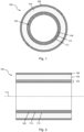
- Fig. 1 shows in cross section and Fig. 2 a longitudinal section of a thermally insulated, flexible pipe 100.
- the pipe 100 has a medium pipe 102, a thermal insulation 104 and a casing 106.
- the thermal insulation 104 is arranged around the medium pipe 102 and is firmly connected to the medium pipe 102, for example welded or glued.
- the thermal insulation 104 is a foamed and hardened polyurethane foam and is used for thermal insulation of the medium to be transported in the medium pipe 102.
- the casing 106 is made of plastic and is arranged around the thermal insulation 104.
- the casing 106 is also firmly connected to the thermal insulation 104, for example welded or glued.
- the casing 106 serves to protect the thermal insulation 104.
- the medium pipe 102 is designed as a flexible, windable and non-metallic thermoplastic composite pipe (TCP).
- the medium pipe 102 has an inner pipe 108, such as an inner liner, in which the medium to be transported can be guided or transported.
- the inner pipe 108 is made of a thermoplastic material, such as high-density polyethylene (HDPE), for example extruded.
- the medium pipe 102 also has a reinforcing layer 110 arranged around the inner pipe 108.
- the reinforcing layer can, for example, comprise one or more, such as two, layers of reinforcing tape which have plastic-impregnated, in particular unidirectionally arranged, fibers, for example glass fibers and/or plastic fibers and/or carbon fibers and/or aramid fibers.
- the layers of reinforcing tape are arranged spirally in different directions around the inner pipe 108 and are firmly connected to it, such as welded or glued.
- the medium pipe 102 also has a protective jacket 112 made of plastic.
- the protective jacket 112 is arranged around the reinforcement layer 110 of the medium pipe 102 and is firmly connected to it, for example welded or glued.
- the thermal insulation 104 is arranged around the protective jacket 112 of the medium pipe 102 and is firmly connected to the protective jacket 112, for example welded or glued.
- the conduit 100 is concentric with an axis 114, such as a longitudinal axis and/or an axis of symmetry.
- Fig. 3 shows a schematic flow diagram of a method for producing the conduit 100.
- the conduit 100 can be designed or manufactured as described above and/or below.
- the medium pipe 102 is inserted into the casing 106 and/or provided with the casing 106.
- the thermal insulation is arranged in a discontinuous or continuous manner between the medium pipe 102 and the casing 106, wherein a liquid and/or foaming composition, such as Plastic composition is introduced as thermal insulation, for example, filled and/or injected and/or sprayed.
- a liquid and/or foaming composition such as Plastic composition
- the liquid or foaming composition, such as plastic composition can be designed as described above and/or below.
- at least one isocyanate component and at least one polyol can be brought together in a mixing head, which are then filled and/or injected and/or sprayed as a mixed, reactive, foaming polyurethane system into the space between the medium pipe 102 and the casing 106.
- the then hardened plastic foam then forms the thermal insulation, which can be designed as described above and/or below.
- the medium pipe 102 can be introduced into a jaw band together with the casing 106 and the annular gap between the medium pipe 102 and the casing 106 can be filled with the liquid and/or foaming composition, such as a plastic composition, as thermal insulation.
- the casing 106 can be provided with the liquid and/or foaming composition, such as a plastic composition, and then introduced into the jaw band together with the medium pipe 102.
- Fig. 4 shows a schematic flow diagram of a method for producing the conduit 100 by means of a continuous process.
- the conduit 100 can be designed or manufactured as described above and/or below.
- a film such as a release film, is formed around the at least one medium pipe 102, such as laid and/or wound.
- the thermal insulation 104 is applied and/or applied to the medium pipe 102.
- a liquid and/or foaming Composition such as plastic composition
- the liquid and/or foaming composition such as plastic composition
- the liquid or foaming composition, such as plastic composition can be designed as described above and/or below.
- At least one isocyanate component and at least one polyol can be brought together in a mixing head, which is then applied and/or applied as a mixed, reactive, foaming polyurethane system to the medium pipe 102, in particular to the outer surface of the medium pipe 102 or its protective casing 112, or is introduced into the space between the film and the at least one medium pipe 102.
- a step S23 the film is formed into a film tube, whereby longitudinal edges of the film are welded and/or glued.
- the thermal insulation 104 is formed at least in its surface area and/or the film is formed smooth or wavy by a forming tool, such as a jaw band.
- a step S25 the sheath 106 is then applied to the formed thermal insulation 104 or to the formed film, for example extruded, such as extruded on.
- the then hardened plastic foam then forms the thermal insulation, which can be designed as described above and/or below.
- isolated features can also be selected from the combinations of features disclosed here and used in combination with other features to define the subject matter of the claim, dissolving any structural and/or functional connection that may exist between the features.
- the order and/or number of all steps of the method or methods can be varied and/or combined. The methods can be combined with one another.
Landscapes
- Engineering & Computer Science (AREA)
- General Engineering & Computer Science (AREA)
- Mechanical Engineering (AREA)
- Thermal Insulation (AREA)
- Rigid Pipes And Flexible Pipes (AREA)
Description
- Die Erfindung betrifft ein thermisch gedämmtes, flexibles Leitungsrohr. Außerdem betrifft die Erfindung ein Verfahren zur Herstellung eines thermisch gedämmten, flexiblen Leitungsrohrs.
- Als flexible Leitungsrohre kommen oft faserverstärke Kunststoffrohre zum Einsatz, die zum Transport unterschiedlicher Medien, wie Wasser, Öl oder Gas, dienen, beispielsweise bei der Onshore- oder Offshore-Förderung für den Transport an Land oder über dem Meeresboden. Flexible Leitungsrohre finden auch beim Fernwärmeleitungsbau Verwendung, um Medien für Wasser- und Heizungsversorgungsanlagen zu transportieren. Insbesondere weisen faserverstärke Kunststoffrohre, wie thermoplastische Kompositrohre ("Thermoplastic Composite Pipes", TCP), eine hohe Druckbeständigkeit mit Arbeitsdrücken zwischen 40 bis 300 bar auf und ermöglichen so einen Transport des Mediums über lange Strecken.
- Thermoplastische Kompositrohre weisen üblicherweise eine Innenlage aus ein- oder mehrschichtigen Innenliner aus thermoplastischem Material auf. Auf diese wird eine Kompositlage, zum Beispiel durch Aufwickeln faserverstärkter Tapes, aufgebracht. Derartige Kompositrohre sind beispielsweise aus dem Dokument
WO 95/07428 A1 WO 2017/048117 A1 bekannt. Weiterer technologischer Hintergrund kann derRU 2 630 810 C2 CH680 815 A5 WO 2013/079455 A1 entnommen werden. - Beim Transport eines, insbesondere warmen oder heißen, Mediums über weite Strecken mittels thermoplastischer Kompositrohre kann es jedoch zu Wärmeverlusten kommen. Die Wärmeverluste können dazu führen, dass sich die Fließfähigkeit des transportierten Mediums verändert oder ein Temperaturniveau für eine nachfolgende Anwendung nicht mehr bereitgestellt werden kann. In solchen Fällen ist dann eine aufwändige und energieintensive Wiedererwärmung des Mediums notwendig. In gleicher Weise kann es beim Transport kalter Medien bei hohen Umgebungstemperaturen notwendig werden, das Medium nochmals aufwändig zu Kühlen.
- Der Erfindung liegt die Aufgabe zugrunde, ein eingangs genanntes Leitungsrohr strukturell und/oder funktionell zu verbessern. Außerdem liegt der Erfindung die Aufgabe zugrunde, ein eingangs genanntes Verfahren zur Herstellung eines Leitungsrohrs funktionell zu verbessern.
- Die Aufgabe wird gelöst mit einem Leitungsrohr mit den Merkmalen des Anspruchs 1. Außerdem wird die Aufgabe gelöst mit einem Verfahren zum Herstellen eines Leitungsrohrs mit den Merkmalen des Anspruchs 13. Anspruch 24 betrifft die Verwendung eines solchen Leitungsrohres. Vorteilhafte Ausführungen und/oder Weiterbildungen sind Gegenstand der Unteransprüche.
- Ein Leitungsrohr kann ein thermisch gedämmtes und/oder flexibles Leitungsrohr sein. Das Leitungsrohr kann zumindest ein Mediumrohr umfassen. Das Leitungsrohr kann beispielsweise zwei, drei, vier oder mehr Mediumrohre umfassen. Das Mediumrohr kann ein Innenrohr, beispielsweise aus Kunststoff, wie thermoplastischem Kunststoff, aufweisen. Das Mediumrohr kann eine um das Innenrohr herum angeordnete Verstärkungsschicht aufweisen. Das Mediumrohr kann einen um die Verstärkungsschicht herum angeordneten Schutzmantel aufweisen.
- Das Leitungsrohr und/oder dessen Mediumrohr kann zum Transport von unterschiedlichen Medien, wie beispielsweise flüssige oder gasförmige Medien, wie Wasser, Öl oder Gas, dienen und/oder ausgebildet sein. Beispielsweise kann das Innenrohr des Mediumrohrs zum Transport von unterschiedlichen Medien, wie zum Beispiel flüssige oder gasförmige Medien, wie Wasser, Öl, wie Rohöl, oder Gas, wie Rohgas, dienen und/oder ausgebildet sein. Das Leitungsrohr kann zum Einsatz bei Wasser-, Öl- oder Gasnetzen bzw. Wasser-, Öl- oder Gasleitungen dienen und/oder ausgebildet sein. Das Leitungsrohr kann zum Einsatz bei der Onshore- oder Offshore-Förderung bzw. dem Onshore- oder Offshore-Transport für den Transport eines Mediums an Land oder über dem Meeresboden dienen und/oder ausgebildet sein. Das Leitungsrohr kann zum Einsatz in Nah- oder Fernwärmenetzen bzw. Nah- oder Fernwärmeleitungen dienen und/oder ausgebildet sein. Das Leitungsrohr kann zum Einsatz bei Geothermienetzen bzw. Geothermienleitungen dienen und/oder ausgebildet sein. Das Leitungsrohr kann beispielsweise ausgebildet sein, um Medien für Wasser- und Heizungsversorgungsanlagen zu transportieren. Das Leitungsrohr kann zum Einsatz bei Trink- oder Abwasserleitungen dienen und/oder ausgebildet sein.
- Das Leitungsrohr und/oder dessen Mediumrohr kann ein, beispielsweise flexibles und/oder wickelbares und/oder nichtmetallisches Rohr, insbesondere Verbundrohr, sein. Das Verbundrohr kann ein thermoplastisches Verbundrohr sein. Das Leitungsrohr und/oder dessen Mediumrohr kann biegbar ausgebildet sein. Das Leitungsrohr und/oder dessen Mediumrohr kann so ausgebildet sein, um zu Ringen und/oder auf Trommeln gewickelt zu werden. Das Leitungsrohr und/oder dessen Mediumrohr kann an Terrain-Bedingungen anpassbar sein. Das Leitungsrohr kann einen Innendurchmesser von etwa 30 bis 200 mm aufweisen. Das Leitungsrohr kann einen Außendurchmesser von etwa 76 bis 355 mm aufweisen.
- Soweit nicht anders angegeben oder es sich aus dem Zusammenhang nicht anders ergibt, beziehen sich die Angaben "axial", "radial" und "in Umfangsrichtung" auf eine Erstreckungsrichtung der Längsachse und/oder Symmetrieachse des Leitungsrohrs und/oder Mediumrohrs. Das Leitungsrohr und/oder dessen Mediumrohr kann konzentrisch zur Längsachse und/oder Symmetrieachse sein. "Axial" entspricht dann einer Erstreckungsrichtung der Längsachse und/oder Symmetrieachse. "Radial" ist dann eine zur Erstreckungsrichtung der Längsachse und/oder Symmetrieachse senkrechte und sich mit der Längsachse und/oder Symmetrieachse schneidende Richtung. "In Umfangsrichtung" entspricht dann einer Kreisbogenrichtung um die Längsachse und/oder Symmetrieachse.
- Das Mediumrohr kann ein faserverstärktes, beispielsweise thermoplastisches, Kunststoffrohr sein. Das Mediumrohr kann ein Mehrschichtrohr sein. Das Mediumrohr kann ein, beispielsweise thermoplastisches, Verbundrohr sein. Das Mediumrohr kann ein verstärktes, wie faserverstärktes, Verbundrohr sein. Das Mediumrohr kann ein Kompositrohr sein. Das Mediumrohr kann ein thermoplastisches Kompositrohr, wie Thermoplastic Composite Pipe (TCP), sein. Das Mediumrohr kann radial innenseitig am Leitungsrohr angeordnet sein. Das Mediumrohr kann ein Basisrohr oder Trägerrohr sein. Das Mediumrohr kann extrudiert oder pultriert sein oder werden. Das Mediumrohr kann mittels eines Extrusionsverfahrens, beispielsweise Koextrusionsverfahrens, oder Pultrusionsverfahrens hergestellt sein oder werden. Beispielsweise kann das Mediumrohr mittels eines Extruders oder mehreren Extrudern und/oder eines Rohrkopfes hergestellt bzw. extrudiert sein oder werden.
- Das Innenrohr des Mediumrohrs kann ein Innenliner sein. Das Innenrohr bzw. der Innenliner kann ein- oder mehrschichtig sein. Das Innenrohr kann ein Mehrschichtrohr sein. Das Innenrohr kann ein Basisrohr oder Trägerrohr sein. Das Innenrohr des Mediumrohres kann radial innenseitig am Mediumrohr angeordnet sein. Das Innenrohr kann ein Kunststoffrohr, wie thermoplastisches Kunststoffrohr, sein. Das Innenrohr des Mediumrohrs kann aus, beispielsweise thermoplastischem, Kunststoff hergestellt sein oder werden. Der Kunststoff kann beispielsweise Polyolefin, Polyethylen, Polyethylen mit hoher Dichte (HDPE), Polypropylen oder Polyamid sein oder aufweisen. Das Innenrohr kann extrudiert oder pultriert sein oder werden. Das Innenrohr kann mittels eines Extrusionsverfahrens oder Pultrusionsverfahrens hergestellt sein oder werden. Beispielsweise kann das Innenrohr mittels eines Extruders und/oder eines Rohrkopfes hergestellt bzw. extrudiert sein oder werden.
- Die Verstärkungsschicht des Mediumrohrs kann mindestens eine Lage aus verstärkenden Fasern aufweisen. Die Fasern können Glasfasern und/oder Kunststofffasern und/oder Kohlefasern und/der Aramidfasern und/oder Basaltfasern und/oder keramische Fasern sein. Der Querschnitt der Fasern kann kreisförmig, rechteckig, oval, elliptisch oder kokonförmig sein. Die Fasern können als Kurzfasern, Langfasern oder Endlosfasern ausgebildet sein. Die Fasern können als Gewebe oder mit einer unidirektionalen Faserlage ausgebildet sein. Die Verstärkungsschicht des Mediumrohrs kann ein Matrixmaterial aus mit Kunststoff imprägnierten Fasern aufweisen. Der Kunststoff kann ein thermoplastischer Kunststoff sein. Der Kunststoff kann beispielsweise Polyolefin, Polyethylen, Polyethylen mit hoher Dichte (HDPE), Polypropylen oder Polyamid sein oder aufweisen. Das Matrixmaterial kann beispielsweise mittels eines Imprägnierverfahrens, Schmelzauftragverfahrens, Schmelzimprägnierverfahrens, Pulverimprägnierverfahrens oder Pultrusionsverfahrens hergestellt sein oder werden.
- Die Verstärkungsschicht des Mediumrohrs kann in radialer Richtung zwischen dem Innenrohr und dem Schutzmantel des Mediumrohrs angeordnet sein. Die Verstärkungsschicht des Mediumrohrs kann mindestens eine erste Lage aus verstärkendem Band aufweisen. Die erste Lage aus verstärkendem Band kann im Wesentlichen spiralförmig in einer ersten spiralförmigen Richtung um das Innenrohr herumgewickelt sein oder werden. Die Verstärkungsschicht kann mindestens eine zweite Lage aus verstärkendem Band aufweisen. Die zweite Lage aus verstärkendem Band kann im Wesentlichen spiralförmig um das Innenrohr und/oder die erste Lage aus verstärkendem Band in einer zweiten spiralförmigen Richtung, beispielsweise entgegen der ersten spiralförmigen Richtung, herumgewickelt sein oder werden. Es können mehrere, wie drei, vier oder mehr, Lagen aus verstärkendem Band vorgesehen sein, welche jeweils in einer spiralförmigen Richtung, insbesondere in unterschiedlichen spiralförmigen Richtungen, um das Innenrohr herumgewickelt sind oder werden. Die mehreren Lagen aus verstärkendem Band können wie die erste und/oder zweite Lage aus verstärkendem Band ausgebildet sein.
- Die erste Lage aus verstärkendem Band kann ein verstärkendes Band umfassen bzw. sein, welches mit Kunststoff imprägnierte Fasern aufweist. Die zweite Lage aus verstärkendem Band kann ein verstärkendes Band umfassen bzw. sein, welches mit Kunststoff imprägnierte Fasern aufweist. Der Kunststoff kann ein thermoplastischer Kunststoff sein. Der Kunststoff kann beispielsweise Polyolefin, Polyethylen, Polyethylen mit hoher Dichte (HDPE), Polypropylen oder Polyamid sein oder aufweisen. Die Fasern der ersten und/oder zweiten Lage aus verstärkendem Band können unidirektional angeordnet und/oder ausgerichtet sein oder werden. Die erste und/oder zweite Lage aus verstärkendem Band kann/können ein mit Kunststoff imprägniertes Faserband, beispielsweise Endlosfasern, Fasergewebe oder Fasergewirk, aufweisen. Der Kunststoff kann ein thermoplastischer Kunststoff sein. Der Kunststoff kann beispielsweise Polyolefin, Polyethylen, Polyethylen mit hoher Dichte (HDPE), Polypropylen oder Polyamid sein oder aufweisen. Die Fasern der ersten und/oder zweiten Lage aus verstärkendem Band können Verstärkungsfasern, beispielsweise Glasfasern und/oder Kunststofffasern und/oder Kohlefasern und/der Aramidfasern und/oder Basaltfasern und/oder keramische Fasern, sein. Der Querschnitt der Fasern kann kreisförmig, rechteckig, oval, elliptisch oder kokonförmig sein. Die Fasern können als Kurzfasern, Langfasern oder Endlosfasern ausgebildet sein. Die Fasern können als Gewebe oder Gewirk oder mit einer unidirektionalen Faserlage ausgebildet und/oder angeordnet sein. Die erste und/oder zweite Lage aus verstärkendem Band kann auch als Tape, wie faserverstärktes Tape, bezeichnet werden. Die erste und/oder zweite Lage aus verstärkendem Band kann beispielsweise mittels eines Imprägnierverfahrens, Schmelzauftragverfahrens, Schmelzimprägnierverfahrens, Pulverimprägnierverfahrens oder Pultrusionsverfahrens hergestellt sein oder werden.
- Die Verstärkungsschicht kann mit dem Innenrohr des Mediumrohrs fest verbunden sein oder werden. Die Verstärkungsschicht kann mit der radial außenseitigen Fläche, wie Außenfläche oder Oberfläche, des Innenrohrs des Mediumrohrs fest verbunden sein oder werden. Die erste und/oder zweite Lage aus verstärkendem Band oder die mehreren Lagen aus verstärkendem Band kann/können mit dem Innenrohr des Mediumrohrs fest verbunden sein oder werden. Die Verstärkungsschicht und/oder dessen erste und/oder zweite Lage aus verstärkendem Band kann mit der äußeren Oberfläche bzw. radial außenseitigen Fläche, wie Außenfläche oder Oberfläche, des Innenrohrs des Mediumrohrs fest verbunden sein oder werden. Die Verbindung kann beispielsweise stoffschlüssig, wie verklebt, verschweißt oder verschmolzen, und/oder kraftschlüssig sein. Beispielsweise kann/können die erste und/oder zweite Lage aus verstärkendem Band mit dem Innenrohr des Mediumrohrs, insbesondere mit der äußeren Oberfläche des Innenrohrs, schmelzverbundartig, wie zum Beispiel verklebt, verschweißt oder verschmolzen, und/oder mittels einer kraftschlusseffektiven Bindungsmethode fest miteinander verbunden sein oder werden. Eine solche Verbindung kann auch als "fester Verbund" und/oder "bonded" bezeichnet werden.
- Die Verstärkungsschicht kann mit dem Schutzmantel des Mediumrohrs fest verbunden sein oder werden. Die Verstärkungsschicht kann mit der radial innenseitigen Fläche, wie Innenfläche oder Oberfläche, des Schutzmantels des Mediumrohrs fest verbunden sein oder werden. Die erste und/oder zweite Lage aus verstärkendem Band oder die mehreren Lagen aus verstärkendem Band kann/können mit dem Schutzmantel des Mediumrohrs fest verbunden sein oder werden. Die Verstärkungsschicht und/oder dessen erste und/oder zweite Lage aus verstärkendem Band kann mit der inneren Oberfläche bzw. radial innenseitigen Fläche, wie Innenfläche oder Oberfläche, des Schutzmantels des Mediumrohrs fest verbunden sein oder werden. Die Verbindung kann beispielsweise stoffschlüssig, wie verklebt, verschweißt oder verschmolzen, und/oder kraftschlüssig sein. Beispielsweise kann/können die erste und/oder zweite Lage aus verstärkendem Band mit dem Schutzmantel des Mediumrohrs, insbesondere mit der inneren Oberfläche des Schutzmantels, schmelzverbundartig, wie zum Beispiel verklebt, verschweißt oder verschmolzen, und/oder mittels einer kraftschlusseffektiven Bindungsmethode fest miteinander verbunden sein oder werden. Eine solche Verbindung kann auch als "fester Verbund" und/oder "bonded" bezeichnet werden.
- Der Schutzmantel des Mediumrohres kann ein äußerer Mantel des Mediumrohres sein. Der Schutzmantel des Mediumrohres kann radial außenseitig am Mediumrohr angeordnet sein. Der Schutzmantel des Mediumrohres kann ein Rohr, wie Kunststoffrohr, oder eine Folie, wie Kunststofffolie, sein. Der Schutzmantel kann ein Folienschlauch, wie Kunststofffolienschlauch, sein. Der Schutzmantel des Mediumrohres kann aus, beispielsweise thermoplastischem, Kunststoff hergestellt sein oder werden. Der Kunststoff kann beispielsweise Polyolefin, Polyethylen, Polyethylen mit hoher Dichte (HDPE), Polypropylen oder Polyamid sein oder aufweisen. Der Schutzmantel kann extrudiert sein oder werden. Der Schutzmantel kann mittels eines Extrusionsverfahrens hergestellt sein oder werden. Beispielsweise kann der Schutzmantel mittels eines Extruders und/oder eines Rohrkopfes hergestellt bzw. extrudiert sein oder werden.
- Das Mediumrohr kann einen Innendurchmesser von etwa 30 bis 200 mm aufweisen. Das Mediumrohr kann einen Außendurchmesser von etwa 40 bis 265 mm aufweisen. Das Mediumrohr kann eine Wanddicke von etwa 5,0 bis 32,5 mm aufweisen.
- Das Leitungsrohr kann eine Wärmedämmung aufweisen. Die Wärmedämmung kann um das Mediumrohr herum angeordnet sein. Das Leitungsrohr kann eine Ummantelung aufweisen. Die Ummantelung kann um die Wärmedämmung herum angeordnet sein. Die Wärmedämmung kann in radialer Richtung zwischen dem Mediumrohr und der Ummantelung des Leitungsrohrs angeordnet sein.
- Die Wärmedämmung kann mit dem Mediumrohr fest verbunden sein oder werden. Die Wärmedämmung kann mit dem Schutzmantel des Mediumrohrs fest verbunden sein oder werden. Die Wärmedämmung kann mit der äußeren Oberfläche des Mediumrohrs und/oder dessen Schutzmantels fest verbunden sein oder werden. Die Wärmedämmung kann mit einer radial außenseitigen Fläche, wie Außenfläche oder Oberfläche, des Mediumrohrs und/oder dessen Schutzmantels fest verbunden sein oder werden. Die Verbindung kann beispielsweise stoffschlüssig, wie verklebt, verschweißt oder verschmolzen, und/oder kraftschlüssig sein. Eine solche Verbindung kann auch als "fester Verbund" und/oder "bonded" bezeichnet werden. Die Verbindung kann durch die Wärmedämmung selbst verursacht sein. Die Wärmedämmung kann klebende Eigenschaften aufweisen.
- Die Wärmedämmung kann mit der Ummantelung des Leitungsrohrs fest verbunden sein oder werden. Die Wärmedämmung kann mit der inneren Oberfläche der Ummantelung fest verbunden sein oder werden. Die Wärmedämmung kann mit einer radial innenseitigen Fläche, wie Innenfläche oder Oberfläche, der Ummantelung des Leitungsrohrs fest verbunden sein oder werden. Die Verbindung kann beispielsweise stoffschlüssig, wie verklebt, verschweißt oder verschmolzen, und/oder kraftschlüssig sein. Eine solche Verbindung kann auch als "fester Verbund" und/oder "bonded" bezeichnet werden. Die Verbindung kann durch die Wärmedämmung selbst verursacht sein.
- Die Wärmedämmung kann zur thermischen Isolation, insbesondere eines im Mediumrohr bzw. im Innenrohr des Mediumrohrs vorhandenen Mediums, dienen. Die Wärmedämmung kann einen Schaumstoff umfassen und/oder daraus hergestellt sein oder werden. Der Schaumstoff kann ein offenzelliger oder geschlossenzelliger Schaumstoff sein. Der Schaumstoff kann ein wärmedämmender Schaumstoff sein und/oder aus einem wärmedämmenden Material hergestellt sein oder werden. Die Wärmedämmung und/oder der Schaumstoff kann einen Kunststoffschaum, beispielsweise einen aufgeschäumten Kunststoffschaum, umfassen und/oder daraus hergestellt sein oder werden. Der Kunststoffschaum kann beispielsweise auf der Basis von Polyurethan (PUR), Polyisocyanurat (PIR), thermoplastischen Polyester oder thermoplastischen Polyolefin hergestellt sein oder werden. Der Kunststoffschaum kann zum Beispiel Polyurethanschaum (PUR), wie Polyurethan-Hartschaum, oder Polyisocyanurat-schaum, wie Polyiso-Hartschaum (PIR), sein. Die Wärmedämmung und/oder dessen Schaumstoff bzw. Kunststoffschaum kann eine Dichte von etwa 40 bis 80 kg/m3 und/oder eine Druckfestigkeit von 0,1 bis 0,5 MPa aufweisen.
- Die Wärmedämmung kann mit einer Schicht ummantelt sein. Die Schicht kann, beispielsweise in radialer Richtung, zwischen der Wärmedämmung und der Ummantelung des Leitungsrohrs angeordnet sein. Beispielsweise kann die Wärmedämmung mit einer Folie, wie Trennfolie, ummantelt sein. Die Schicht und/oder Folie kann ein Folienschlauch, wie Kunststofffolienschlauch, sein. Die Schicht und/oder Folie kann aus, beispielsweise thermoplastischem, Kunststoff hergestellt sein oder werden. Der Kunststoff kann beispielsweise Polyolefin, Polyethylen, Polyethylen mit hoher Dichte (HDPE), Polypropylen oder Polyamid sein oder aufweisen. Die Schicht und/oder Folie kann extrudiert sein oder werden. Die Schicht und/oder Folie kann mittels eines Extrusionsverfahrens hergestellt sein oder werden. Beispielsweise kann die Schicht und/oder Folie mittels eines Extruders und/oder eines Rohrkopfes oder eines Folienextruders hergestellt bzw. extrudiert sein oder werden.
- Die Wärmedämmung kann als ein- oder mehrlagige Wärmedämmung ausgebildet sein. Die Wärmedämmung kann eine oder mehrere, beispielsweise zwei, drei, vier oder mehr, Schichten, wie Wärmedämmschichten, aufweisen. Jede Schicht der Wärmedämmung kann aus einem wärmedämmenden Material, wie Schaumstoff und/oder Kunststoffschaum, hergestellt sein oder werden. Der Schaumstoff bzw. Kunststoffschaum kann wie vorstehend und/oder nachfolgend beschrieben ausgebildet und/oder hergestellt sein oder werden. Die Schichten der Wärmedämmung können unterschiedlich ausgebildet, beispielsweise mit unterschiedlichen Schaumstoffen bzw. Kunststoffschäumen ausgebildet sein oder werden. Die Schichten der Wärmedämmung können jeweils durch eine Zwischenschicht, wie Folie, voneinander getrennt ausgebildet sein oder werden. Die Zwischenschicht und/oder Folie kann ein Folienschlauch, wie Kunststofffolienschlauch, sein. Die Zwischenschicht und/oder Folie kann aus, beispielsweise thermoplastischem, Kunststoff hergestellt sein oder werden. Der Kunststoff kann beispielsweise Polyolefin, Polyethylen, Polyethylen mit hoher Dichte (HDPE), Polypropylen oder Polyamid sein oder aufweisen. Die Zwischenschicht und/oder Folie kann extrudiert sein oder werden. Die Zwischenschicht und/oder Folie kann mittels eines Extrusionsverfahrens hergestellt sein oder werden. Beispielsweise kann die Zwischenschicht und/oder Folie mittels eines Extruders und/oder eines Rohrkopfes hergestellt bzw. extrudiert sein oder werden.
- Die Wärmedämmung kann einen Innendurchmesser von etwa 40 bis 265 mm aufweisen. Die Wärmedämmung kann einen Außendurchmesser von etwa 72bis 348 mm aufweisen. Die Wärmedämmung kann eine Wanddicke von etwa 16 bis 50 mm aufweisen. Eine oder jede Schicht, wie Wärmedämmschicht, der Wärmedämmung kann eine Wanddicke von etwa 16 bis 50 mm aufweisen.
- Die Ummantelung des Leitungsrohrs kann radial außenseitig am Leitungsrohr angeordnet sein oder werden. Die Ummantelung des Leitungsrohrs kann ein Außenrohr, beispielsweise ein flexibles und/oder biegbares Außenrohr, oder eine Folie, beispielsweise ein flexibler Folienschlauch, sein. Die Ummantelung kann aus, beispielsweise thermoplastischem, Kunststoff hergestellt, beispielsweise extrudiert, sein oder werden. Der Kunststoff kann Polyolefin, Polyethylen, Polyethylen mit hoher Dichte (HDPE), Polypropylen oder Polyamid sein oder aufweisen. Die Ummantelung kann eine Kunststofffolie, zum Beispiel ein Kunststofffolienschlauch, sein. Die Ummantelung des Leitungsrohrs kann eine Wanddicke von etwa 1,0 bis 5,0 mm, beispielsweise von etwa 2 mm aufweisen. Beispielsweise kann die Ummantelung mittels eines Extruders und/oder eines Rohrkopfes hergestellt bzw. extrudiert sein oder werden.
- Das Leitungsrohr kann eine Folie, wie Trennfolie und/oder Kunststofffolie, aufweisen. Die Folie kann zwischen der Wärmedämmung und der Ummantelung angeordnet sein. Die Folie, beispielsweise die innere Oberfläche der Folie, kann mit der Wärmedämmung fest verbunden, beispielsweise stoffschlüssig, wie verklebt, verschweißt oder verschmolzen, und/oder kraftschlüssig verbunden, sein. Die Folie, beispielsweise die äußere Oberfläche der Folie, kann mit der Ummantelung fest verbunden, beispielsweise stoffschlüssig, wie verklebt, verschweißt oder verschmolzen, und/oder kraftschlüssig verbunden, sein. Die Folie kann ein Schlauch, wie Folienschlauch, sein. Die Folie kann aus, beispielsweise thermoplastischem, Kunststoff hergestellt, beispielsweise extrudiert, sein oder werden. Der Kunststoff kann Polyolefin, Polyethylen, Polyethylen mit geringer Dichte (LD-PE), lineares Polyethylen mit niederer / geringer Dichte (LLD-PE), Polyethylen mit hoher Dichte (HDPE), Polypropylen oder Polyamid sein oder aufweisen. Beispielsweise kann die Folie mittels eines Extruders, wie Folienextruders, hergestellt bzw. extrudiert sein oder werden.
- Die Wärmedämmung bzw. zumindest ein Oberflächenbereich der Wärmedämmung und/oder die Folie und/oder die Ummantelung des Leitungsrohrs kann glatt und/oder gewellt ausgebildet sein oder werden. Die radial außenseitige Fläche, wie Außenfläche oder Oberfläche, der Wärmedämmung und/oder der Folie und/oder der Ummantelung kann glatt und/oder gewellt ausgebildet sein oder werden. Die Wärmedämmung und/oder die Folie und/oder die Ummantelung des Leitungsrohrs und/oder dessen radial außenseitige Fläche kann gleichmäßig und/oder ungleichmäßig gewellt sein. Die Wärmedämmung und/oder die Folie und/oder die Ummantelung des Leitungsrohrs und/oder dessen radial außenseitige Fläche kann ein Wellenprofil aufweisen. Das Wellenprofil kann Wellentäler und Wellenberge aufweisen. Die Wellentäler können größer, beispielsweise breiter, wie in Längsrichtung des Leitungsrohrs breiter, sein als die Wellenberge. Die Wellenberge können größer, beispielsweise breiter, wie in Längsrichtung des Leitungsrohrs breiter, sein als die Wellentäler. Das Wellenprofil kann Wellenflanken aufweisen. Die Wellenflanken können, beispielsweise steile / steiler, ansteigende und/oder, beispielsweise flache / flacher, abfallende Wellenflanken aufweisen. Die Wärmedämmung und/oder die Folie und/oder die Ummantelung des Leitungsrohrs und/oder dessen radial außenseitige Fläche kann korrugiert ausgebildet sein oder werden. Die Wärmedämmung und/oder die Folie und/oder die Ummantelung des Leitungsrohrs kann flexibel und/oder biegbar ausgebildet sein oder werden. Die Folie und/oder Ummantelung des Leitungsrohrs kann eine Schutzschicht sein.
- Das Leitungsrohr kann mittels eines Extrusionsverfahrens, beispielsweise Koextrusionsverfahrens, bzw. einer Extrusionsanlage hergestellt sein oder werden. Beispielsweise kann das Leitungsrohr mittels eines Extruders oder mehreren Extrudern und/oder eines Rohrkopfes hergestellt bzw. extrudiert sein oder werden. Das Leitungsrohr kann mittels eines Backenbandverfahrens bzw. einer Backenbandanlage hergestellt sein oder werden.
- Eine Verwendung eines vorstehend und/oder nachfolgend beschriebenen Leitungsrohrs kann für den Transport von Öl, wie Rohöl, Gas, wie Rohgas, Wasser, Öl-Wasser-Gemisch, Öl-Gas-Gemisch oder anderen aus den genannten Stoffen kombinierte Gemische sein und/oder dienen.
- Bei einem Verfahren zur Herstellung eines Leitungsrohrs, wie thermisch gedämmten, flexiblen Leitungsrohrs, kann die Wärmedämmung in diskontinuierlicher oder kontinuierlicher Arbeitsweise zwischen dem Mediumrohr und der Ummantelung angeordnet werden. Bei einem Verfahren zur Herstellung eines Leitungsrohrs, wie thermisch gedämmten, flexiblen Leitungsrohrs, kann in kontinuierlicher Arbeitsweise die Wärmedämmung auf das Mediumrohr aufgebracht werden. Das Leitungsrohr kann wie vorstehend und/oder nachfolgend beschrieben ausgebildet sein oder werden. Das Leitungsrohr kann so hergestellt werden, dass das Leitungsrohr zumindest ein Mediumrohr, eine Wärmedämmung und eine Ummantelung umfasst, wobei das zumindest eine Mediumrohr ein Innenrohr aus thermoplastischem Kunststoff, eine Verstärkungsschicht und einen Schutzmantel aufweist. Die Wärmedämmung kann um das zumindest eine Mediumrohr herum angeordnet bzw. angebracht und/oder befestigt werden. Die Ummantelung kann um die Wärmedämmung herum angeordnet bzw. angebracht und/oder befestigt werden.
- Das zumindest eine Mediumrohr und/oder dessen Innenrohr kann extrudiert, beispielsweise koextrudiert, werden. Das Innenrohr des Mediumrohrs kann auf einer Trommel aufgewickelt und/oder gelagert und/oder von der Trommel abgewickelt werden. Die Verstärkungsschicht kann auf das Innenrohr des Mediumrohrs aufgebracht werden, beispielsweise durch Aufwickeln bzw. um das Innenrohr herumwickeln. Die Verstärkungsschicht kann mit dem Innenrohr des Mediumrohrs fest verbunden werden, beispielsweise stoffschlüssig, wie verklebt, verschweißt oder verschmolzen, und/oder kraftschlüssig und/oder "gebonded". Der Schutzmantel kann auf das mit der Verstärkungsschicht versehene Innenrohr des Mediumrohrs aufgebracht, beispielsweise extrudiert, wie aufextrudiert, oder aufgewickelt bzw. herumgewickelt werden. Das mit der Verstärkungsschicht versehene Innenrohr des Mediumrohrs kann in den Schutzmantel eingeführt und/oder eingeschoben werden. Der Schutzmantel kann mit der Verstärkungsschicht des Mediumrohrs fest verbunden werden, beispielsweise stoffschlüssig, wie verklebt, verschweißt oder verschmolzen, und/oder kraftschlüssig und/oder "gebonded".
- Das Mediumrohr kann auf einer Trommel aufgewickelt und/oder gelagert und/oder von der Trommel abgewickelt werden. Das Mediumrohr kann, beispielsweise kontinuierlich oder diskontinuierlich, bereitgestellt werden. Zum Beispiel kann ein Teil eines Mediumrohrs bereitgestellt werden. Das Teil des Mediumrohrs kann im Wesentlichen geradlinig oder als Formteil bereitgestellt werden. Das Formteil kann gebogen sein oder werden und/oder zumindest abschnittsweise I-, T- oder U-förmig ausgebildet sein oder werden. Beispielsweise kann das Mediumrohr als T-Stück oder als Rohrstange bereitgestellt werden.
- Die Ummantelung kann, beispielsweise kontinuierlich oder diskontinuierlich, bereitgestellt werden. Die Ummantelung kann vorgefertigt sein oder werden. Das Mediumrohr und/oder ein Teil des Mediumrohrs kann in die Ummantelung eingeführt und/oder eingeschoben werden. Zwischen dem Mediumrohr bzw. dem Teil des Mediumrohrs und der Ummantelung können Abstandshalter bereitgestellt werden. Durch die Abstandshalter kann ein Raum, wie Hohlraum, Spalt oder Ringspalt, zwischen dem Mediumrohr und der Ummantelung gebildet werden. In den Raum zwischen dem Mediumrohr und der Ummantelung kann eine flüssige und/oder aufschäumende Zusammensetzung, wie Kunststoffzusammensetzung, als Wärmedämmung eingebracht, beispielsweise eingefüllt und/oder eingespritzt und/oder eingesprüht, werden. Die Wärmedämmung kann wie vorstehend und/oder nachfolgend beschrieben ausgebildet sein oder werden.
- Eine flüssige und/oder aufschäumende Zusammensetzung, wie Kunststoffzusammensetzung, kann als Wärmedämmung auf die, insbesondere bereitgestellte, Ummantelung, beispielsweise auf die innere Oberfläche der Ummantelung, aufgebracht werden. Eine flüssige und/oder aufschäumende Zusammensetzung, wie Kunststoffzusammensetzung, kann als Wärmedämmung auf eine Folie, wie Kunststofffolie, aufgebracht werden. Die Folie kann eine Trennfolie sein. Die Folie kann, beispielsweise kontinuierlich oder diskontinuierlich, bereitgestellt werden.
- Die mit der flüssigen und/oder aufschäumenden Zusammensetzung bzw. Kunststoffzusammensetzung versehene Ummantelung und/oder Folie kann dann zusammen mit dem Mediumrohr in einem Formwerkzeug, wie Backenband, eingeführt werden.
- Das Mediumrohr und ein aus einer Folie kontinuierlich gebildeter Folienschlauch kann in einem Formwerkzeug, wie Backenband, bereitgestellt werden. Dabei kann das Mediumrohr innerhalb des Folienschlauches angeordnet werden, beispielsweise so, dass zwischen dem Mediumrohr und dem Folienschlauch ein Raum, wie Hohlraum, Spalt oder Ringspalt, ausgebildet wird. Hierfür können Abstandshalter zwischen dem Mediumrohr und dem Folienschlauch vorgesehen bzw. bereitgestellt werden. In den Raum kann eine flüssige und/oder aufschäumende Zusammensetzung, wie Kunststoffzusammensetzung, als Wärmedämmung eingebracht, beispielsweise eingefüllt und/oder eingespritzt und/oder eingesprüht, werden.
- Die Form des Backenbands, insbesondere dessen innere Oberfläche, kann die Form, wie die radial äußere Oberfläche bzw. Außenschicht, der Ummantelung und/oder der Folie und/oder der Wärmedämmung vorgeben und/oder ausbilden. Beispielsweise kann die innere Oberfläche des Backenbands ein Wellenprofil aufweisen. Das Wellenprofil des Backenbands kann so ausgebildet sein, dass das vorstehend und/oder nachfolgend beschriebene Wellenprofil der Ummantelung und/oder Folie und/oder Wärmedämmung ausgebildet werden kann. Das Backenband kann ein Formwerkzeug sein. Das Formwerkzeug kann Formhälften, beispielsweise zwei Formhälften, aufweisen. Die Formhälften können gegenüberliegend angeordnet sein oder werden. Zwei Formhälften können ein Formwerkzeugpaar bilden. Es können mehrere Formwerkzeugpaare vorgesehen sein. Das Formwerkzeug und/oder dessen Formhälften können mitlaufend ausgebildet sein. Das Formwerkzeug und/oder dessen Formhälften können beheizbar oder kühlbar ausgebildet sein. Die Formhälften bzw. dessen inneren Oberflächen können das Wellenprofil aufweisen. Das Backenband und/oder Formwerkzeug kann dazu ausgebildet sein, das Leitungsrohrs, wie thermisch gedämmte, flexible Leitungsrohr, zu erzeugen bzw. herzustellen.
- Bei einer diskontinuierlichen Arbeitsweise kann beispielsweise das Mediumrohr in Teilen, wie Stangen / Rohrstangen, oder als vorgefertigte Formteile, wie Bögen oder T-Stücke, herausgeschnitten und/oder vorgefertigt und/oder bereitgestellt werden. Die Stangen / Rohrstangen können unterschiedliche Längen, zum Beispiel bis zu etwa 16 m pro Teil aufweisen. Die Teile des Mediumrohrs können in die Ummantelung und/oder eine Folie, wie Folienschlauch, eingefügt werden, beispielsweise mittels Abstandshaltern. Die Folie kann eine Kunststofffolie und/oder Trennfolie sein. Alternativ können die Teile des Mediumrohrs mit der Ummantelung und/oder Folie versehen werden. Die Ummantelung und/oder Folie kann vorgefertigt sein oder werden. Der Hohlraum zwischen dem Teil des Mediumrohrs und der Ummantelung und/oder Folie kann mit einer flüssigen und/oder aufschäumenden Zusammensetzung, wie Kunststoffzusammensetzung, als Wärmedämmung gefüllt, wie ausgefüllt, werden.
- Bei einer kontinuierlichen Arbeitsweise kann beispielsweise das Mediumrohr auf Trommeln gelagert und/oder mit den Trommeln zur Herstellungsanlage gebracht werden. Eine flüssige und/oder aufschäumenden Zusammensetzung, wie Kunststoffzusammensetzung, kann als Wärmedämmung in einem kontinuierlichen Prozess um das Mediumrohr herum angebracht und/oder aufgebracht werden. Die flüssige und/oder aufschäumenden Zusammensetzung, wie Kunststoffzusammensetzung, kann auf die Ummantelung und/oder eine Folie, wie Folienschlauch und/oder Trennfolie und/oder Kunststofffolie, aufgebracht werden. Das Mediumrohr und die Ummantelung und/oder Folie kann dann in ein Backenband eingeführt werden.
- Bei einer kontinuierlichen Arbeitsweise kann die Wärmedämmung auf das zumindest eine Mediumrohr aufgebracht und/oder aufgetragen werden, beispielsweise kontinuierlich aufgebracht und/oder aufgetragen werden. Eine flüssige und/oder aufschäumende Kunststoffzusammensetzung kann als Wärmedämmung auf das Mediumrohr, beispielsweise auf die äußere Oberfläche des Mediumrohrs und/oder dessen Schutzmantels, aufgebracht und/oder aufgetragen werden. Die Ummantelung kann, beispielsweise nahtlos, auf die Wärmedämmung, beispielsweise direkt oder indirekt, aufgebracht, beispielsweise extrudiert, wie aufextrudiert, werden.
- Das zumindest eine Mediumrohr kann von einer Trommel abgewickelt werden. Das zumindest eine Mediumrohr kann in Längsrichtung des Mediumrohrs bereitgestellt und/oder transportiert und/oder von der Trommel abgezogen werden. Das zumindest eine Mediumrohr kann, beispielsweise mittels einer Heizeinrichtung, wie Infrarotheizeinrichtung oder Elektrowiderstandsheizeinrichtung, vorerwärmt bzw. vorgewärmt werden. Eine Folie, wie Kunststofffolie und/oder Trennfolie, kann um das Mediumrohr herum geformt, wie gelegt und/oder gewickelt, werden. Eine flüssige und/oder aufschäumende Kunststoffzusammensetzung kann als Wärmedämmung, beispielsweise mittels einer Pistole oder mittels eines Mischkopfs, in einen Raum, wie Spalt, zwischen der Folie und dem zumindest einen Mediumrohr eingebracht, wie eingespritzt, eingesprüht oder eingelassen, werden. Unter Einlassen kann auch ein Einlaufen oder Einfließen lassen der flüssigen und/oder aufschäumenden Kunststoffzusammensetzung in den Raum zwischen der Folie und dem zumindest einen Mediumrohr verstanden werden. Der Raum kann ein Dämmstoffausformungsbereich sein. Der Dämmstoffausformungsbereich kann durch die Folie, insbesondere die Innenseite der Folie, und das zumindest eine Mediumrohr, insbesondere die Außenseite des zumindest einen Mediumrohrs, definiert und/oder gebildet sein. Das Einbringen der flüssigen und/oder aufschäumenden Kunststoffzusammensetzung kann kontinuierlich erfolgen. Die Folie kann zu einem Schlauch, wie Folienschlauch, geformt werden. Dabei können Längskanten der Folie verschweißt und/oder verklebt werden. Die Ausformung der Folie zu einem Schlauch kann kontinuierlich erfolgen. Die Ausformung der Folie zu einem Schlauch kann unmittelbar nach dem Umlegen der Folie um das zumindest eine Mediumrohr und/oder unmittelbar nach dem Einbringen der flüssigen und/oder aufschäumenden Kunststoffzusammensetzung in den durch die Folie und das zumindest eine Mediumrohr definierten und/oder gebildeten Raum erfolgen. Die Wärmedämmung kann zumindest in ihrem Oberflächenbereich und/oder die Folie / Folienschlauch kann/können durch ein Formwerkzeug, wie Backenband, geformt werden, beispielsweise glatt oder wellenförmig geformt werden. Das Formen der Wärmedämmung und/oder der Folie / Folienschlauch kann durch das Formwerkzeug in einem ersten Teilschritt und in einem ersten Teilbereich und in einem weiteren Teilschritt in einem weiteren Teilbereich erfolgen. Die Teilbereiche und/oder Teilschritte können, beispielsweise unmittelbar, hintereinander sein. Das Formen der Wärmedämmung und/oder der Folie / Folienschlauch kann kontinuierlich erfolgen. Die Folie / Folienschlauch kann ausgebildet sein und/oder dazu dienen, ein Haften, wie Anhaften, beispielsweise der Kunststoffzusammensetzung bzw. Wärmedämmung, an dem Formwerkzeug zu verhindern. Das Formwerkzeug kann beheizt oder gekühlt werden. Dadurch kann das Aushärten der Kunststoffzusammensetzung beeinflusst, beispielsweise verzögert oder beschleunigt, und/oder ein Aushärtezeitpunkt eingestellt werden. Die flüssige und/oder aufschäumende Kunststoffzusammensetzung kann aufschäumen und/oder aushärten, beispielsweise vor und/oder während dem Formen durch das Formwerkzeug. Die flüssige und/oder aufschäumende Kunststoffzusammensetzung kann nach dem Formen durch das Formwerkzeug zu der bzw. als Wärmedämmung ausgehärtet sein. Die Ummantelung kann, beispielsweise nahtlos, auf die ausgeformte und/oder ausgehärtete Wärmedämmung und/oder auf die, insbesondere ausgeformte, Folie / Folienschlauch aufgebracht, beispielsweise extrudiert, wie aufextrudiert, werden. Das Extrudieren kann mittels eines Extruders, wie Einschneckenextruder, und/oder mittels eines Rohrkopfes erfolgen. Das Aufbringen der Ummantelung kann kontinuierlich erfolgen. Die Ummantelung kann die Form der äußeren Oberfläche der ausgeformten und/oder ausgehärteten Wärmedämmung und/oder der, insbesondere ausgeformten, Folie / Folienschlauch annehmen und/oder aufweisen. Das Leitungsrohr kann dann mittels einer Kühleinrichtung, wie Kühlungsbadeinrichtung, gekühlt werden und/oder auf eine Trommel aufgewickelt werden. Die Kühleinrichtung und/oder die Kühlungsbadeinrichtung kann eine Wasserkühlungseinrichtung und/oder Kühlwassereinrichtung sein. Die Kühleinrichtung kann Düsen, wie Spritzdüsen, aufweisen, mittels denen Kühlwasser auf das Leitungsrohr gespitzt werden kann.
- Das zumindest eine Mediumrohr kann wie vorstehend und/oder nachfolgend ausgebildet sein oder werden. Die Folie kann wie vorstehend und/oder nachfolgend ausgebildet sein oder werden. Die Ummantelung kann wie vorstehend und/oder nachfolgend ausgebildet sein oder werden. Das Formwerkzeug kann wie vorstehend und/oder nachfolgend ausgebildet sein. Die Zusammensetzung bzw. Kunststoffzusammensetzung kann wie vorstehend und/oder nachfolgend ausgebildet sein oder werden. Die Zusammensetzung bzw. Kunststoffzusammensetzung kann der vorstehend und/oder nachfolgend beschriebene aufschäumende Schaumstoff und/oder Kunststoffschaum sein. Die Wärmedämmung kann durch Aufschäumen und/oder Aushärten der flüssigen und/oder aufschäumenden Zusammensetzung bzw. Kunststoffzusammensetzung ausgebildet werden. Die Zusammensetzung bzw. Kunststoffzusammensetzung kann ein reagierendes bzw. reaktives Kunststoffsystem, beispielsweise ein Polyurethansystem oder Polyisozyanoratsystem, sein. Die Zusammensetzung bzw. Kunststoffzusammensetzung kann ein reaktiver und/oder aufschäumender Schaumstoff und/oder Kunststoffschaum sein. Beispielsweise kann mindestens eine Isocyanatkomponente und mindestens ein Polyol zusammengeführt werden, die das reaktive Kunststoffsystem bilden. Das Kunststoffsystem kann aufgeschäumt und/oder ausgehärtet werden. Die Zusammensetzung / Kunststoffzusammensetzung bzw. das Kunststoffsystem kann mittels eines Mischkopfs gemischt und/oder erzeugt und/oder bereitgesellt werden.
- Eine Vorrichtung zum Herstellen eines thermisch gedämmten, flexiblen Leitungsrohrs kann zumindest eine Vorratstrommel zum Bevorraten eines Mediumrohrs, ein Rollensystem, eine Heizeinrichtung zum Vorwärmen des Mediumrohrs, eine Vorratsspule zum Bevorraten einer Folie, eine Zuführeinrichtung zum Zuführen der Folie, eine Pistole und/oder Mischkopf zum Einbringen eines flüssigen und/oder aufschäumenden Kunststoffzusammensetzung als Wärmedämmung, eine Folienschweißeinrichtung zum Bilden eines Folienschlauchs, ein Formwerkzeug, wie Backenband, zum Formen der Wärmedämmung und/oder Folie, eine Ummantelungsaufbringeinheit, wie Extruder und/oder Rohrkopf, zum Aufbringen einer Ummantelung und/oder eine Kühleinrichtung, wie Kühlungsbadeinrichtung, zum Kühlen des Leitungsrohrs. Die Kühleinrichtung und/oder Kühlungsbadeinrichtung kann eine Wasserkühlungseinrichtung und/oder Kühlwassereinrichtung sein. Die Kühleinrichtung kann Düsen, wie Spritzdüsen, aufweisen, die ausgebildet sind, Kühlwasser auf das Leitungsrohr zu spritzen. Die Vorrichtung kann ferner einen Abzug, wie Bandabzug, und/oder eine weitere Vorratstrommel zum Aufwickeln und/oder Bevorraten des hergestellten Leitungsrohrs aufweisen. Die Vorrichtung zum Herstellen des Leitungsrohrs kann zur Durchführung zumindest eines der vorstehend und/oder nachfolgend beschriebenen Verfahren ausgebildet und/oder eingerichtet sein. Die Vorrichtung zum Herstellen des Leitungsrohrs kann ausgebildet und/oder eingerichtet sein, das vorstehend und/oder nachfolgend beschriebene Leitungsrohr herzustellen.
- Mit der Erfindung kann eine gleichmäßige Wärmedämmung an allen Stellen des Leitungsrohrs ermöglicht werden. Wärmeverluste des zu transportierenden Mediums können vermieden oder zumindest stark reduziert werden. Die Fließfähigkeit des zu transportierenden Mediums kann zumindest im Wesentlichen unverändert aufrechterhalten werden. Geforderte Temperaturniveaus können eingehalten werden.
- Nachfolgend werden Ausführungsbeispiele der Erfindung unter Bezugnahme auf Figuren näher beschrieben, dabei zeigen schematisch und beispielhaft:
- Fig. 1
- ein thermisch gedämmtes, flexibles Leitungsrohr im Querschnitt;
- Fig. 2
- das Leitungsrohr gemäß
Fig. 1 im Längsschnitt; - Fig. 3
- ein Flussdiagramm eines Verfahrens zur Herstellung des Leitungsrohrs gemäß
Fig. 1 und 2 ; und - Fig. 4
- ein Flussdiagramm eines weiteren Verfahrens zur Herstellung des Leitungsrohrs gemäß
Fig. 1 und 2 . -
Fig. 1 zeigt im Querschnitt undFig. 2 im Längsschnitt schematisch ein thermisch gedämmtes, flexibles Leitungsrohr 100. Das Leitungsrohr 100 weist ein Mediumrohr 102, eine Wärmedämmung 104 und eine Ummantelung 106 auf. Die Wärmedämmung 104 ist um das Mediumrohr 102 herum angeordnet und mit dem Mediumrohr 102 fest verbunden, beispielsweise verschweißt oder verklebt. Die Wärmedämmung 104 ist ein aufgeschäumter und ausgehärteter Polyurethanschaum und dient zur Wärmedämmung des im Mediumrohr 102 zu transportierenden Mediums. Die Ummantelung 106 ist aus Kunststoff hergestellt und um die Wärmedämmung 104 herum angeordnet. Die Ummantelung 106 ist mit der Wärmedämmung 104 ebenfalls fest verbunden, beispielsweise verschweißt oder verklebt. Die Ummantelung 106 dient zum Schutz der Wärmedämmung 104. - Das Mediumrohr 102 ist als ein flexibles, wickelbares und nichtmetallisches, thermoplastisches Verbundrohr ("thermoplastic composite pipe", TCP) ausgebildet. Das Mediumrohr 102 weist ein Innenrohr 108, wie Innenliner, auf, in dem das zu transportierende Medium geführt bzw. transportiert werden kann. Das Innenrohr 108 ist aus einem thermoplastischen Kunststoff, wie einem Polyethylen mit hoher Dichte (HDPE), hergestellt, beispielsweise extrudiert. Das Mediumrohr 102 weist ferner eine um das Innenrohr 108 angeordnete Verstärkungsschicht 110 auf. Die Verstärkungsschicht kann beispielsweise eine oder mehrere, wie zwei, Lagen aus verstärkendem Band umfassen, die mit Kunststoff imprägnierte, insbesondere unidirektional angeordnete, Fasern, beispielsweise Glasfasern und/oder Kunststofffasern und/oder Kohlefasern und/oder Aramidfasern, aufweisen. Die Lagen aus verstärkendem Band sind in unterschiedlichen Richtungen spiralförmig um das Innenrohr 108 herum angeordnet und mit diesem fest verbunden, wie verschweißt oder verklebt. Das Mediumrohr 102 weist ferner einen aus Kunststoff hergestellten Schutzmantel 112 auf. Der Schutzmantel 112 ist um die Verstärkungsschicht 110 des Mediumrohrs 102 herum angeordnet und mit dieser fest verbunden, wie verschweißt oder verklebt. Die Wärmedämmung 104 ist um den Schutzmantel 112 des Mediumrohrs 102 herum angeordnet und mit dem den Schutzmantel 112 fest verbunden, beispielsweise verschweißt oder verklebt.
- Das Leitungsrohr 100 ist konzentrisch zu einer Achse 114, wie Längsachse und/oder Symmetrieachse.
-
Fig. 3 zeigt schematisch ein Flussdiagramm eines Verfahrens zur Herstellung des Leitungsrohrs 100. Das Leitungsrohr 100 kann wie vorstehend und/oder nachfolgend beschrieben ausgebildet bzw. hergestellt sein oder werden. - In einem Schritt S11 wird das Mediumrohr 102 in die Ummantelung 106 eingeführt und/oder mit der Ummantelung 106 versehen.
- In einem Schritt S12 wird die Wärmedämmung in diskontinuierlicher oder kontinuierlicher Arbeitsweise zwischen dem Mediumrohr 102 und der Ummantelung 106 angeordnet, wobei in den Raum zwischen dem Mediumrohr 102 und der Ummantelung 106 eine flüssige und/oder aufschäumende Zusammensetzung, wie Kunststoffzusammensetzung, als Wärmedämmung eingebracht, beispielsweise eingefüllt und/oder eingespritzt und/oder eingesprüht, wird. Die flüssige bzw. aufschäumende Zusammensetzung, wie Kunststoffzusammensetzung, kann wie vorstehend und/oder nachfolgend beschrieben ausgebildet sein oder werden. Beispielsweise kann mindestens eine Isocyanatkomponente und mindestens ein Polyol in einem Mischkopf zusammengeführt werden, die dann als gemischtes, reaktives, aufschäumendes Polyurethansystem in den Raum zwischen dem Mediumrohr 102 und der Ummantelung 106 eingefüllt und/oder eingespritzt und/oder eingesprüht werden. Der dann ausgehärtete Kunststoffschaum bildet dann die Wärmedämmung, welche wie vorstehend und/oder nachfolgend beschrieben ausgebildet sein kann.
- Bei einer kontinuierlichen Arbeitsweise kann beispielsweise das Mediumrohr 102 zusammen mit der Ummantelung 106 in ein Backenband eingeführt und der zwischen dem Mediumrohr 102 und der Ummantelung 106 vorhandene Ringspalt mit der flüssigen und/oder aufschäumenden Zusammensetzung, wie Kunststoffzusammensetzung, als Wärmedämmung eingebracht werden. Alternativ kann die Ummantelung 106 mit der flüssigen und/oder aufschäumenden Zusammensetzung, wie Kunststoffzusammensetzung, versehen werden und dann zusammen mit dem Mediumrohr 102 in das Backenband eingebracht werden.
- Im Übrigen wird ergänzend insbesondere auf
Fign. 1 und 2 und die zugehörige Beschreibung verwiesen. -
Fig. 4 zeigt schematisch ein Flussdiagramm eines Verfahrens zur Herstellung des Leitungsrohrs 100 mittels eines kontinuierlichen Prozesses. Das Leitungsrohr 100 kann wie vorstehend und/oder nachfolgend beschrieben ausgebildet bzw. hergestellt sein oder werden. - In einem Schritt S21 wird eine Folie, wie Trennfolie, um das zumindest eine Mediumrohr 102 herum geformt, wie gelegt und/oder gewickelt.
- In einem Schritt S22 wird die Wärmedämmung 104 auf das Mediumrohr 102 aufgebracht und/oder aufgetragen. Dabei wird eine flüssige und/oder aufschäumende Zusammensetzung, wie Kunststoffzusammensetzung, als Wärmedämmung 104 um das Mediumrohr 102 herum aufgebracht und/oder aufgetragen, wobei die flüssige und/oder aufschäumende Zusammensetzung, wie Kunststoffzusammensetzung, als Wärmedämmung 104 in einen Raum, wie Spalt, zwischen der Folie und dem zumindest einen Mediumrohr 102 eingebracht, wie eingespritzt, eingesprüht oder eingelassen, wird. Die flüssige bzw. aufschäumende Zusammensetzung, wie Kunststoffzusammensetzung, kann wie vorstehend und/oder nachfolgend beschrieben ausgebildet sein oder werden. Beispielsweise kann mindestens eine Isocyanatkomponente und mindestens ein Polyol in einem Mischkopf zusammengeführt werden, die dann als gemischtes, reaktives, aufschäumendes Polyurethansystem auf das Mediumrohr 102, insbesondere auf die äußere Oberfläche des Mediumrohrs 102 bzw. dessen Schutzmantels 112, aufgebracht und/oder aufgetragen wird bzw. in den Raum zwischen der Folie und dem zumindest einem Mediumrohr 102 eingebracht wird.
- In einem Schritt S23 wird die Folie zu einem Folienschlauch geformt, wobei Längskanten der Folie verschweißt und/oder verklebt werden.
- In einem Schritt S24 wird die Wärmedämmung 104 zumindest in ihrem Oberflächenbereich und/oder die Folie durch ein Formwerkzeug, wie Backenband, glatt oder wellenförmig geformt.
- In einem Schritt S25 wird dann die Ummantelung 106 auf die ausgeformte Wärmedämmung 104 bzw. auf ausgeformte Folie aufgebracht, beispielsweise extrudiert, wie aufextrudiert.
- Der dann ausgehärtete Kunststoffschaum bildet dann die Wärmedämmung, welche wie vorstehend und/oder nachfolgend beschrieben ausgebildet sein kann.
- Im Übrigen wird ergänzend insbesondere auf
Fign. 1 bis 3 und die zugehörige Beschreibung verwiesen. - Mit "kann" sind insbesondere optionale Merkmale der Erfindung bezeichnet. Demzufolge gibt es auch Weiterbildungen und/oder Ausführungsbeispiele der Erfindung, die zusätzlich oder alternativ das jeweilige Merkmal oder die jeweiligen Merkmale aufweisen.
- Aus den vorliegend offenbarten Merkmalskombinationen können bedarfsweise auch isolierte Merkmale herausgegriffen und unter Auflösung eines zwischen den Merkmalen gegebenenfalls bestehenden strukturellen und/oder funktionellen Zusammenhangs in Kombination mit anderen Merkmalen zur Abgrenzung des Anspruchsgegenstands verwendet werden. Die Reihenfolge und/oder Anzahl aller Schritte des Verfahrens bzw. der Verfahren kann variiert und/oder kombiniert werden. Die Verfahren können miteinander kombiniert werden.
-
- 100
- Leitungsrohr
- 102
- Mediumrohr
- 104
- Wärmedämmung
- 106
- Ummantelung
- 108
- Innenrohr
- 110
- Verstärkungsschicht
- 112
- Schutzmantel
- 114
- Achse
- S11
- Schritt zum Einführen bzw. Versehen des Mediumrohrs mit der Ummantelung
- S12
- Schritt zum Aufbringen bzw. Einbringen der flüssigen und/oder aufschäumenden Zusammensetzung, wie Kunststoffzusammensetzung
- S21
- Schritt zum Formen einer Folie um das Mediumrohr herum
- S22
- Schritt zum Aufbringen der flüssigen und/oder aufschäumenden Zusammensetzung, wie Kunststoffzusammensetzung
- S23
- Schritt zum Formen der Folie zu einem Folienschlauch
- S24
- Schritt zum Formen der Wärmedämmung und/oder Folie in einem Formwerkzeug
- S25
- Schritt zum Aufbringen der Ummantelung
Claims (24)
- Thermisch gedämmtes, flexibles Leitungsrohr (100), umfassend zumindest ein Mediumrohr(102), eine um das Mediumrohr (102) herum angeordnete Wärmedämmung (104) und eine um die Wärmedämmung (104) herum angeordnete Ummantelung (106), wobei das zumindest eine Mediumrohr (102) ein Innenrohr (108) aus thermoplastischem Kunststoff, eine um das Innenrohr (108) herum angeordnete Verstärkungsschicht (110) und einen um die Verstärkungsschicht (110) herum angeordneten Schutzmantel (112) aufweist, dadurch gekennzeichnet, dass die Verstärkungsschicht (110) mit dem Innenrohr (108) und/oder mit dem Schutzmantel (112) des Mediumrohrs (102) verschweißt oder verschmolzen ist.
- Leitungsrohr (100) nach Anspruch 1, dadurch gekennzeichnet, dass die Verstärkungsschicht (110) mindestens eine erste Lage aus verstärkendem Band aufweist, das im Wesentlichen spiralförmig in einer ersten spiralförmigen Richtung um das Innenrohr (108) gewickelt ist.
- Leitungsrohr (100) nach Anspruch 2, dadurch gekennzeichnet, dass die Verstärkungsschicht (110) mindestens eine zweite Lage aus verstärkendem Band aufweist, das im Wesentlichen spiralförmig um die erste Lage aus verstärkendem Band in einer zweiten spiralförmigen Richtung entgegen der ersten spiralförmigen Richtung gewickelt ist.
- Leitungsrohr (100) nach Anspruch 2 oder 3, dadurch gekennzeichnet, dass die erste Lage aus verstärkendem Band und/oder die zweite Lage aus verstärkendem Band ein verstärkendes Band umfasst, welches mit Kunststoff, wie Polyolefin, Polyethylen, Polyethylen mit hoher Dichte (HDPE), Polypropylen oder Polyamid, imprägnierte, insbesondere unidirektional angeordnete, Fasern, wie Glasfasern und/oder Kunststofffasern und/oder Kohlefasern und/oder Aramidfasern, aufweist.
- Leitungsrohr (100) nach wenigstens einem der vorhergehenden Ansprüche,
dadurch gekennzeichnet, dass das Mediumrohr (102) ein, insbesondere flexibles und/oder wickelbares und/oder nichtmetallisches, thermoplastisches Verbundrohr ist. - Leitungsrohr (100) nach wenigstens einem der vorhergehenden Ansprüche,
dadurch gekennzeichnet, dass die Wärmedämmung (104) mit dem Mediumrohr (102), insbesondere mit der äußeren Oberfläche des Mediumrohrs (102), und/oder mit der Ummantelung (106) des Leitungsrohrs (100), insbesondere mit der inneren Oberfläche der Ummantelung (106), fest verbunden, insbesondere stoffschlüssig, wie verklebt, verschweißt oder verschmolzen, und/oder kraftschlüssig verbunden, ist. - Leitungsrohr (100) nach wenigstens einem der vorhergehenden Ansprüche,
dadurch gekennzeichnet, dass das Leitungsrohr (100) eine Folie, wie Trennfolie, aufweist, wobei die Folie zwischen der Wärmedämmung (104) und der Ummantelung (106) angeordnet ist, wobei die Folie, insbesondere die innere Oberfläche der Folie, mit der Wärmedämmung (104) fest verbunden, insbesondere stoffschlüssig, wie verklebt, verschweißt oder verschmolzen, und/oder kraftschlüssig verbunden, ist und/oder die Folie, insbesondere die äußere Oberfläche der Folie, mit der Ummantelung (106) fest verbunden, insbesondere stoffschlüssig, wie verklebt, verschweißt oder verschmolzen, und/oder kraftschlüssig verbunden, ist. - Leitungsrohr (100) nach wenigstens einem der vorhergehenden Ansprüche,
dadurch gekennzeichnet, dass die Wärmedämmung (104) einen Schaumstoff, insbesondere einen offenzelligen oder geschlossenzelligen Schaumstoff, umfasst und/oder daraus hergestellt ist. - Leitungsrohr (100) nach wenigstens einem der vorhergehenden Ansprüche,
dadurch gekennzeichnet, dass die Wärmedämmung (104) einen aufgeschäumten Kunststoffschaum, insbesondere auf der Basis von Polyurethan, Polyisocyanurat, thermoplastischen Polyester oder thermoplastischen Polyolefin, umfasst und/oder daraus hergestellt ist. - Leitungsrohr (100) nach wenigstens einem der vorhergehenden Ansprüche,
dadurch gekennzeichnet, dass die Ummantelung (106) des Leitungsrohrs (100) ein Außenrohr, insbesondere ein flexibles Außenrohr, oder eine Folie, insbesondere ein flexibler Folienschlauch, ist. - Leitungsrohr (100) nach wenigstens einem der vorhergehenden Ansprüche,
dadurch gekennzeichnet, dass die Wärmedämmung (104) und/oder die Folie und/oder die Ummantelung (106) des Leitungsrohrs (100) glatt oder gewellt, wie gleichmäßig oder ungleichmäßig gewellt, oder korrugiert ausgebildet ist. - Leitungsrohr (100) nach wenigstens einem der vorhergehenden Ansprüche,
dadurch gekennzeichnet, dass das Innenrohr (108) und/oder der Schutzmantel (112) des Mediumrohres (102) und/oder die Folie und/oder die Ummantelung (106) des Leitungsrohres (100) aus thermoplastischem Kunststoff, wie Polyolefin, Polyethylen, Polyethylen mit hoher Dichte (HDPE), Polypropylen oder Polyamid hergestellt, insbesondere extrudiert, ist. - Verfahren zur Herstellung eines thermisch gedämmten, flexiblen Leitungsrohrs (100), umfassend zumindest ein Mediumrohr (102), eine Wärmedämmung (104) und eine Ummantelung (106), wobei das zumindest eine Mediumrohr (102) ein Innenrohr (108) aus thermoplastischem Kunststoff, eine Verstärkungsschicht (110) und einen Schutzmantel (112) aufweist, dadurch gekennzeichnet, dass die Verstärkungsschicht (110) mit dem Innenrohr (108) und/oder mit dem Schutzmantel (112) des Mediumrohrs (102) verschweißt oder verschmolzen ist, bei dem die Wärmedämmung (104) in diskontinuierlicher oder kontinuierlicher Arbeitsweise zwischen dem Mediumrohr (102) und der Ummantelung (106) angeordnet wird (S12).
- Verfahren nach Anspruch 13, dadurch gekennzeichnet, dass das Mediumrohr (102) in die Ummantelung (106) eingeführt (S11) und/oder mit der Ummantelung (106) versehen wird (S11) und in den Raum zwischen dem Mediumrohr (102) und der Ummantelung (106) eine flüssige und/oder aufschäumende Kunststoffzusammensetzung als Wärmedämmung (104) eingebracht wird (S12).
- Verfahren nach Anspruch 13, dadurch gekennzeichnet, dass eine flüssige und/oder aufschäumende Kunststoffzusammensetzung als Wärmedämmung (104) auf die Ummantelung (106), insbesondere auf die innere Oberfläche der Ummantelung (106), oder auf eine Folie, aufgebracht wird (S12), die dann zusammen mit dem Mediumrohr (102) in einem Backenband eingeführt wird.
- Verfahren nach Anspruch 13, dadurch gekennzeichnet, dass das Mediumrohr (102) und ein aus einer Folie kontinuierlich gebildeter Folienschlauch (106) in einem Backenband bereitgestellt wird, wobei das Mediumrohr (102) innerhalb des Folienschlauches (106) so angeordnet ist (S11), dass zwischen dem Mediumrohr (102) und dem Folienschlauch (106) ein Spalt, insbesondere Ringspalt, ausgebildet wird, und dass dann in den Spalt eine flüssige und/oder aufschäumende Kunststoffzusammensetzung als Wärmedämmung (104) eingebracht wird (S12).
- Verfahren nach wenigstens einem der vorhergehenden Ansprüche 15 bis 16,
dadurch gekennzeichnet, dass die Form des Backenbands die Form der Ummantelung (106) und/oder der Folie vorgibt und/oder ausbildet. - Verfahren zur Herstellung eines thermisch gedämmten, flexiblen Leitungsrohrs (100), umfassend zumindest ein Mediumrohr (102), eine Wärmedämmung (104) und eine Ummantelung (106), wobei das zumindest eine Mediumrohr (102) ein Innenrohr (108) aus thermoplastischem Kunststoff, eine Verstärkungsschicht (110) und einen Schutzmantel (112) aufweist, dadurch gekennzeichnet, dass die Verstärkungsschicht (110) mit dem Innenrohr (108) und/oder mit dem Schutzmantel (112) des Mediumrohrs (102) verschweißt oder verschmolzen ist, bei dem in kontinuierlicher Arbeitsweise die Wärmedämmung (104) auf das zumindest eine Mediumrohr (102) aufgebracht und/oder aufgetragen (S22) und die Ummantelung (106) auf die Wärmedämmung (104) aufgebracht, insbesondere extrudiert, wie aufextrudiert, wird (S25).
- Verfahren nach Anspruch 18, bei dem eine flüssige und/oder aufschäumende Kunststoffzusammensetzung als Wärmedämmung (104) auf das zumindest eine Mediumrohr (102), insbesondere auf die äußere Oberfläche des zumindest einen Mediumrohrs (102) und/oder dessen Schutzmantels (112), aufgebracht und/oder aufgetragen wird (S22).
- Verfahren nach Anspruch 18 oder 19, bei dem eine Folie, wie Trennfolie, um das zumindest eine Mediumrohr (102) herum geformt, wie gelegt und/oder gewickelt, wird (S21), und eine flüssige und/oder aufschäumende Kunststoffzusammensetzung als Wärmedämmung (104) in einen Raum, wie Spalt, zwischen der Folie und dem zumindest einen Mediumrohr (102) eingebracht, wie eingespritzt, eingesprüht oder eingelassen, wird (S22).
- Verfahren nach Anspruch 20, bei dem die Folie zu einem Folienschlauch geformt wird, wobei Längskanten der Folie verschweißt und/oder verklebt werden (S23).
- Verfahren nach wenigstens einem der vorhergehenden Ansprüche 18 bis 21, bei dem die Wärmedämmung (104) zumindest in ihrem Oberflächenbereich und/oder die Folie durch ein Formwerkzeug, wie Backenband, glatt oder wellenförmig geformt werden (S24).
- Verfahren nach wenigstens einem der vorhergehenden Ansprüche 18 bis 22, bei dem die Ummantelung (106) auf die ausgeformte Wärmedämmung (104) und/oder auf die, insbesondere ausgeformte, Folie aufgebracht, insbesondere extrudiert, wie aufextrudiert, wird (S25).
- Verwendung des Leitungsrohrs (100) nach wenigstens einem der vorhergehenden Ansprüche 1 bis 12 für den Transport von Öl, wie Rohöl, Gas, wie Rohgas, Wasser, Öl-Wasser-Gemisch, Öl-Gas-Gemisch oder anderen aus den genannten Stoffen kombinierte Gemische.
Priority Applications (2)
| Application Number | Priority Date | Filing Date | Title |
|---|---|---|---|
| EP21190596.3A EP4134581B1 (de) | 2021-08-10 | 2021-08-10 | Thermisch gedämmtes, flexibles leitungsrohr, verfahren zur herstellung eines solchen leitungsrohrs und dessen verwendung |
| PCT/EP2022/066983 WO2023016687A1 (de) | 2021-08-10 | 2022-06-22 | Thermisch gedämmtes, flexibles leitungsrohr und verfahren zur herstellung eines solchen leitungsrohrs |
Applications Claiming Priority (1)
| Application Number | Priority Date | Filing Date | Title |
|---|---|---|---|
| EP21190596.3A EP4134581B1 (de) | 2021-08-10 | 2021-08-10 | Thermisch gedämmtes, flexibles leitungsrohr, verfahren zur herstellung eines solchen leitungsrohrs und dessen verwendung |
Publications (3)
| Publication Number | Publication Date |
|---|---|
| EP4134581A1 EP4134581A1 (de) | 2023-02-15 |
| EP4134581C0 EP4134581C0 (de) | 2024-12-04 |
| EP4134581B1 true EP4134581B1 (de) | 2024-12-04 |
Family
ID=77274748
Family Applications (1)
| Application Number | Title | Priority Date | Filing Date |
|---|---|---|---|
| EP21190596.3A Active EP4134581B1 (de) | 2021-08-10 | 2021-08-10 | Thermisch gedämmtes, flexibles leitungsrohr, verfahren zur herstellung eines solchen leitungsrohrs und dessen verwendung |
Country Status (2)
| Country | Link |
|---|---|
| EP (1) | EP4134581B1 (de) |
| WO (1) | WO2023016687A1 (de) |
Citations (11)
| Publication number | Priority date | Publication date | Assignee | Title |
|---|---|---|---|---|
| US3654967A (en) | 1970-07-17 | 1972-04-11 | Uniroyal Inc | Textile-reinforced all-polymeric hose and method of making same |
| EP0375608A1 (de) | 1988-12-11 | 1990-06-27 | "Brugg"-Kabel Ag | Flexibles Medientransportrohr |
| CH680815A5 (en) * | 1989-06-15 | 1992-11-13 | Brugg Rohrsystem Ag | Low cost flexible conveyor pipe - has fatigue-resistant expandable metal permeation barrier fully covering inner tube |
| WO2013079455A1 (de) | 2011-11-28 | 2013-06-06 | Basf Se | Verfahren zur herstellung von gedämmten mantelrohren im kontinuierlichen herstellungsprozess |
| US20140238977A1 (en) | 2013-02-22 | 2014-08-28 | Thercom Holdings, Llc | Composite article with induction layer and methods of forming and use thereof |
| WO2016083727A1 (fr) | 2014-11-24 | 2016-06-02 | Technip France | Couche d'isolation thermique pour conduite tubulaire flexible sous-marine |
| RU2630810C2 (ru) | 2014-09-26 | 2017-09-13 | Общество с ограниченной ответственностью Научное инновационное предприятие "Дельта-Т" | Теплоизолированная гибкая полимерная труба, армированная лентами (варианты) |
| US10132441B2 (en) | 2008-05-01 | 2018-11-20 | Cabot Corporation | Manufacturing and installation of insulated pipes or elements thereof |
| DE202019004158U1 (de) | 2019-02-22 | 2020-02-11 | Uponor Innovation Ab | Isoliertes Rohr |
| WO2020068408A1 (en) | 2018-09-24 | 2020-04-02 | Exxonmobil Chemical Patents Inc. | Thermoplastic blends and composites for flexible pipes |
| EP3904092A1 (de) | 2020-04-29 | 2021-11-03 | Radius-Kelit Infrastructure Gesellschaft m.b.H. | Flexibles verstärktes mehrlagiges polymerrohr |
Family Cites Families (2)
| Publication number | Priority date | Publication date | Assignee | Title |
|---|---|---|---|---|
| FI933877A7 (fi) | 1993-09-06 | 1995-03-07 | Plastilon Oy | Luja kestomuovipohjainen komposiittiputki |
| NL2015434B1 (en) | 2015-09-14 | 2017-03-29 | Pipelife Nederland Bv | High pressure pipe and method for producing such pipe. |
-
2021
- 2021-08-10 EP EP21190596.3A patent/EP4134581B1/de active Active
-
2022
- 2022-06-22 WO PCT/EP2022/066983 patent/WO2023016687A1/de not_active Ceased
Patent Citations (11)
| Publication number | Priority date | Publication date | Assignee | Title |
|---|---|---|---|---|
| US3654967A (en) | 1970-07-17 | 1972-04-11 | Uniroyal Inc | Textile-reinforced all-polymeric hose and method of making same |
| EP0375608A1 (de) | 1988-12-11 | 1990-06-27 | "Brugg"-Kabel Ag | Flexibles Medientransportrohr |
| CH680815A5 (en) * | 1989-06-15 | 1992-11-13 | Brugg Rohrsystem Ag | Low cost flexible conveyor pipe - has fatigue-resistant expandable metal permeation barrier fully covering inner tube |
| US10132441B2 (en) | 2008-05-01 | 2018-11-20 | Cabot Corporation | Manufacturing and installation of insulated pipes or elements thereof |
| WO2013079455A1 (de) | 2011-11-28 | 2013-06-06 | Basf Se | Verfahren zur herstellung von gedämmten mantelrohren im kontinuierlichen herstellungsprozess |
| US20140238977A1 (en) | 2013-02-22 | 2014-08-28 | Thercom Holdings, Llc | Composite article with induction layer and methods of forming and use thereof |
| RU2630810C2 (ru) | 2014-09-26 | 2017-09-13 | Общество с ограниченной ответственностью Научное инновационное предприятие "Дельта-Т" | Теплоизолированная гибкая полимерная труба, армированная лентами (варианты) |
| WO2016083727A1 (fr) | 2014-11-24 | 2016-06-02 | Technip France | Couche d'isolation thermique pour conduite tubulaire flexible sous-marine |
| WO2020068408A1 (en) | 2018-09-24 | 2020-04-02 | Exxonmobil Chemical Patents Inc. | Thermoplastic blends and composites for flexible pipes |
| DE202019004158U1 (de) | 2019-02-22 | 2020-02-11 | Uponor Innovation Ab | Isoliertes Rohr |
| EP3904092A1 (de) | 2020-04-29 | 2021-11-03 | Radius-Kelit Infrastructure Gesellschaft m.b.H. | Flexibles verstärktes mehrlagiges polymerrohr |
Non-Patent Citations (2)
| Title |
|---|
| ANONYMOUS: " Dickes Fell bei Kälte und bei Hitze", MASTERFLEX, 7 October 2009 (2009-10-07), XP093311511, Retrieved from the Internet <URL: https://www.masterflex.de/aktuelle-meldungen/news/dickes-fell-bei-kaelte-und-bei-hitze/> |
| KATALOGBLATT 16.1; APRIL 2009 (NOT FOUND ON THE INTERNET AND COPY IS NOT GOOD ENOUGH FOR PDF-ING) |
Also Published As
| Publication number | Publication date |
|---|---|
| EP4134581A1 (de) | 2023-02-15 |
| EP4134581C0 (de) | 2024-12-04 |
| WO2023016687A1 (de) | 2023-02-16 |
Similar Documents
| Publication | Publication Date | Title |
|---|---|---|
| EP3112124B1 (de) | Verfahren zur beschichtung einer rohrleitung | |
| DE69622723T2 (de) | Rohrformiges Produkt, Extrusionsvorrichtung und Verfahren | |
| DE19629678A1 (de) | Verfahren zur Herstellung eines wärmeisolierten Leitungsrohres | |
| DE3018194A1 (de) | Verfahren zum herstellen von rohren, platten oder behaeltern aus kunststoff | |
| CH653950A5 (de) | Verfahren zur herstellung eines waermeisolierten leitungsrohres. | |
| EP3359858B1 (de) | Auskleidungsschlauch für die kanalsanierung sowie verfahren zur herstellung eines solchen | |
| EP3758910B1 (de) | Verfahren und vorrichtung zur herstellung eines wärmegedämmten leitungsrohrs | |
| CH660907A5 (de) | Waermeisoliertes leitungsrohr und verfahren zu seiner herstellung. | |
| EP2137451B1 (de) | Kunststoffrohr | |
| AT398053B (de) | Verfahren und rohrverbindungsstück zur kontinuierlichen herstellung umschäumter, thermisch isolierter leitungsrohre | |
| WO2014134745A1 (de) | Wärmegedämmtes gewelltes leitungsrohr | |
| EP4134581B1 (de) | Thermisch gedämmtes, flexibles leitungsrohr, verfahren zur herstellung eines solchen leitungsrohrs und dessen verwendung | |
| DE4323838B4 (de) | Verfahren zur Herstellung eines mehrschichtigen Leitungsrohres | |
| CH710709A1 (de) | Leitungsrohr mit thermischer Dämmung. | |
| DE29615423U1 (de) | Wärmeisoliertes Leitungsrohr | |
| EP4118370A1 (de) | Thermoplastischer schlauch sowie eine vorrichtung und ein verfahren zur herstellung eines solchen | |
| EP1628059B1 (de) | Verfahren zur Herstellung von glasfaserverstärkten Kunststoffrohren beliebigen Querschnitts mit Sandwichstruktur | |
| EP4261012B1 (de) | Verfahren zur herstellung eines flexiblen, thermoplastischen verbundrohrs sowie thermoplastisches verbundrohr | |
| EP1055783A1 (de) | Mehrschicht-Wandstruktur | |
| EP1640652B1 (de) | Thermisch isoliertes, flexibles Leitungsrohr und Verfahren zur und Vorrichtung für die Herstellung eines Leitungsrohrs | |
| EP1208962B1 (de) | Verfahren zur kontinuierlichen Herstellung eines wenigstens drei Lagen aufweisenden Isolierschlauchs | |
| DE102012211651A1 (de) | Verfahren zur Herstellung eines Wickelrohrs | |
| EP2431158A1 (de) | Verfahren zur Herstellung thermisch isolierter Rohre, insbesondere Kupferrohre | |
| DE20011306U1 (de) | Flexibles wärmeisoliertes Leitungsrohr | |
| DE102023136192A1 (de) | Verfahren zur kontinuierlichen Herstellung eines wärmegedämmten Wellrohrs sowie dadurch erhaltenes wärmegedämmtes Wellrohr |
Legal Events
| Date | Code | Title | Description |
|---|---|---|---|
| PUAI | Public reference made under article 153(3) epc to a published international application that has entered the european phase |
Free format text: ORIGINAL CODE: 0009012 |
|
| STAA | Information on the status of an ep patent application or granted ep patent |
Free format text: STATUS: THE APPLICATION HAS BEEN PUBLISHED |
|
| AK | Designated contracting states |
Kind code of ref document: A1 Designated state(s): AL AT BE BG CH CY CZ DE DK EE ES FI FR GB GR HR HU IE IS IT LI LT LU LV MC MK MT NL NO PL PT RO RS SE SI SK SM TR |
|
| STAA | Information on the status of an ep patent application or granted ep patent |
Free format text: STATUS: REQUEST FOR EXAMINATION WAS MADE |
|
| 17P | Request for examination filed |
Effective date: 20230801 |
|
| RBV | Designated contracting states (corrected) |
Designated state(s): AL AT BE BG CH CY CZ DE DK EE ES FI FR GB GR HR HU IE IS IT LI LT LU LV MC MK MT NL NO PL PT RO RS SE SI SK SM TR |
|
| STAA | Information on the status of an ep patent application or granted ep patent |
Free format text: STATUS: EXAMINATION IS IN PROGRESS |
|
| 17Q | First examination report despatched |
Effective date: 20240208 |
|
| RAP3 | Party data changed (applicant data changed or rights of an application transferred) |
Owner name: RK INFRA GESMBH Owner name: FIBRON PIPE GESMBH |
|
| GRAP | Despatch of communication of intention to grant a patent |
Free format text: ORIGINAL CODE: EPIDOSNIGR1 |
|
| STAA | Information on the status of an ep patent application or granted ep patent |
Free format text: STATUS: GRANT OF PATENT IS INTENDED |
|
| RIC1 | Information provided on ipc code assigned before grant |
Ipc: B29C 48/21 20190101ALI20240830BHEP Ipc: B29C 48/151 20190101ALI20240830BHEP Ipc: B29C 48/09 20190101ALI20240830BHEP Ipc: F16L 11/10 20060101ALI20240830BHEP Ipc: F16L 59/02 20060101ALI20240830BHEP Ipc: F16L 59/153 20060101ALI20240830BHEP Ipc: B29C 48/00 20190101ALI20240830BHEP Ipc: F16L 59/147 20060101AFI20240830BHEP |
|
| INTG | Intention to grant announced |
Effective date: 20240912 |
|
| GRAS | Grant fee paid |
Free format text: ORIGINAL CODE: EPIDOSNIGR3 |
|
| GRAA | (expected) grant |
Free format text: ORIGINAL CODE: 0009210 |
|
| STAA | Information on the status of an ep patent application or granted ep patent |
Free format text: STATUS: THE PATENT HAS BEEN GRANTED |
|
| AK | Designated contracting states |
Kind code of ref document: B1 Designated state(s): AL AT BE BG CH CY CZ DE DK EE ES FI FR GB GR HR HU IE IS IT LI LT LU LV MC MK MT NL NO PL PT RO RS SE SI SK SM TR |
|
| REG | Reference to a national code |
Ref country code: CH Ref legal event code: EP |
|
| REG | Reference to a national code |
Ref country code: DE Ref legal event code: R096 Ref document number: 502021005988 Country of ref document: DE |
|
| REG | Reference to a national code |
Ref country code: IE Ref legal event code: FG4D Free format text: LANGUAGE OF EP DOCUMENT: GERMAN |
|
| U01 | Request for unitary effect filed |
Effective date: 20241222 |
|
| U07 | Unitary effect registered |
Designated state(s): AT BE BG DE DK EE FI FR IT LT LU LV MT NL PT RO SE SI Effective date: 20250114 |
|
| PG25 | Lapsed in a contracting state [announced via postgrant information from national office to epo] |
Ref country code: HR Free format text: LAPSE BECAUSE OF FAILURE TO SUBMIT A TRANSLATION OF THE DESCRIPTION OR TO PAY THE FEE WITHIN THE PRESCRIBED TIME-LIMIT Effective date: 20241204 |
|
| PG25 | Lapsed in a contracting state [announced via postgrant information from national office to epo] |
Ref country code: ES Free format text: LAPSE BECAUSE OF FAILURE TO SUBMIT A TRANSLATION OF THE DESCRIPTION OR TO PAY THE FEE WITHIN THE PRESCRIBED TIME-LIMIT Effective date: 20241204 |
|
| PG25 | Lapsed in a contracting state [announced via postgrant information from national office to epo] |
Ref country code: NO Free format text: LAPSE BECAUSE OF FAILURE TO SUBMIT A TRANSLATION OF THE DESCRIPTION OR TO PAY THE FEE WITHIN THE PRESCRIBED TIME-LIMIT Effective date: 20250304 |
|
| PG25 | Lapsed in a contracting state [announced via postgrant information from national office to epo] |
Ref country code: GR Free format text: LAPSE BECAUSE OF FAILURE TO SUBMIT A TRANSLATION OF THE DESCRIPTION OR TO PAY THE FEE WITHIN THE PRESCRIBED TIME-LIMIT Effective date: 20250305 |
|
| PG25 | Lapsed in a contracting state [announced via postgrant information from national office to epo] |
Ref country code: RS Free format text: LAPSE BECAUSE OF FAILURE TO SUBMIT A TRANSLATION OF THE DESCRIPTION OR TO PAY THE FEE WITHIN THE PRESCRIBED TIME-LIMIT Effective date: 20250304 |
|
| PG25 | Lapsed in a contracting state [announced via postgrant information from national office to epo] |
Ref country code: SM Free format text: LAPSE BECAUSE OF FAILURE TO SUBMIT A TRANSLATION OF THE DESCRIPTION OR TO PAY THE FEE WITHIN THE PRESCRIBED TIME-LIMIT Effective date: 20241204 |
|
| PG25 | Lapsed in a contracting state [announced via postgrant information from national office to epo] |
Ref country code: PL Free format text: LAPSE BECAUSE OF FAILURE TO SUBMIT A TRANSLATION OF THE DESCRIPTION OR TO PAY THE FEE WITHIN THE PRESCRIBED TIME-LIMIT Effective date: 20241204 |
|
| PG25 | Lapsed in a contracting state [announced via postgrant information from national office to epo] |
Ref country code: IS Free format text: LAPSE BECAUSE OF FAILURE TO SUBMIT A TRANSLATION OF THE DESCRIPTION OR TO PAY THE FEE WITHIN THE PRESCRIBED TIME-LIMIT Effective date: 20250404 |
|
| PG25 | Lapsed in a contracting state [announced via postgrant information from national office to epo] |
Ref country code: SK Free format text: LAPSE BECAUSE OF FAILURE TO SUBMIT A TRANSLATION OF THE DESCRIPTION OR TO PAY THE FEE WITHIN THE PRESCRIBED TIME-LIMIT Effective date: 20241204 |
|
| PG25 | Lapsed in a contracting state [announced via postgrant information from national office to epo] |
Ref country code: CZ Free format text: LAPSE BECAUSE OF FAILURE TO SUBMIT A TRANSLATION OF THE DESCRIPTION OR TO PAY THE FEE WITHIN THE PRESCRIBED TIME-LIMIT Effective date: 20241204 |
|
| PLBI | Opposition filed |
Free format text: ORIGINAL CODE: 0009260 |
|
| PLAX | Notice of opposition and request to file observation + time limit sent |
Free format text: ORIGINAL CODE: EPIDOSNOBS2 |
|
| U20 | Renewal fee for the european patent with unitary effect paid |
Year of fee payment: 5 Effective date: 20250826 |
|
| 26 | Opposition filed |
Opponent name: MASTERFLEX SE Effective date: 20250904 |