EP4134572A1 - Getriebeschaltvorrichtung, elektrisches antriebssystem und fahrzeug mit neuer energie - Google Patents
Getriebeschaltvorrichtung, elektrisches antriebssystem und fahrzeug mit neuer energie Download PDFInfo
- Publication number
- EP4134572A1 EP4134572A1 EP22189674.9A EP22189674A EP4134572A1 EP 4134572 A1 EP4134572 A1 EP 4134572A1 EP 22189674 A EP22189674 A EP 22189674A EP 4134572 A1 EP4134572 A1 EP 4134572A1
- Authority
- EP
- European Patent Office
- Prior art keywords
- power transmission
- intermediate shaft
- gear
- unit
- clutch
- Prior art date
- Legal status (The legal status is an assumption and is not a legal conclusion. Google has not performed a legal analysis and makes no representation as to the accuracy of the status listed.)
- Pending
Links
- 230000005540 biological transmission Effects 0.000 claims abstract description 263
- 239000003638 chemical reducing agent Substances 0.000 claims description 19
- 230000007246 mechanism Effects 0.000 description 10
- 230000006870 function Effects 0.000 description 9
- 230000014509 gene expression Effects 0.000 description 7
- 238000011161 development Methods 0.000 description 6
- 230000008859 change Effects 0.000 description 5
- 230000033001 locomotion Effects 0.000 description 5
- 239000000470 constituent Substances 0.000 description 4
- 238000010586 diagram Methods 0.000 description 4
- 230000004044 response Effects 0.000 description 3
- 230000000881 depressing effect Effects 0.000 description 2
- 230000008901 benefit Effects 0.000 description 1
- 230000008878 coupling Effects 0.000 description 1
- 238000010168 coupling process Methods 0.000 description 1
- 238000005859 coupling reaction Methods 0.000 description 1
- 238000013461 design Methods 0.000 description 1
- 238000003745 diagnosis Methods 0.000 description 1
- 230000009977 dual effect Effects 0.000 description 1
- 230000000694 effects Effects 0.000 description 1
- 230000005674 electromagnetic induction Effects 0.000 description 1
- 239000000446 fuel Substances 0.000 description 1
- 230000010365 information processing Effects 0.000 description 1
- 238000000034 method Methods 0.000 description 1
- 238000012544 monitoring process Methods 0.000 description 1
- 230000008569 process Effects 0.000 description 1
- 230000001360 synchronised effect Effects 0.000 description 1
- 230000001052 transient effect Effects 0.000 description 1
Images


Classifications
-
- F—MECHANICAL ENGINEERING; LIGHTING; HEATING; WEAPONS; BLASTING
- F16—ENGINEERING ELEMENTS AND UNITS; GENERAL MEASURES FOR PRODUCING AND MAINTAINING EFFECTIVE FUNCTIONING OF MACHINES OR INSTALLATIONS; THERMAL INSULATION IN GENERAL
- F16H—GEARING
- F16H3/00—Toothed gearings for conveying rotary motion with variable gear ratio or for reversing rotary motion
- F16H3/02—Toothed gearings for conveying rotary motion with variable gear ratio or for reversing rotary motion without gears having orbital motion
- F16H3/20—Toothed gearings for conveying rotary motion with variable gear ratio or for reversing rotary motion without gears having orbital motion exclusively or essentially using gears that can be moved out of gear
- F16H3/22—Toothed gearings for conveying rotary motion with variable gear ratio or for reversing rotary motion without gears having orbital motion exclusively or essentially using gears that can be moved out of gear with gears shiftable only axially
- F16H3/30—Toothed gearings for conveying rotary motion with variable gear ratio or for reversing rotary motion without gears having orbital motion exclusively or essentially using gears that can be moved out of gear with gears shiftable only axially with driving and driven shafts not coaxial
- F16H3/32—Toothed gearings for conveying rotary motion with variable gear ratio or for reversing rotary motion without gears having orbital motion exclusively or essentially using gears that can be moved out of gear with gears shiftable only axially with driving and driven shafts not coaxial and an additional shaft
-
- F—MECHANICAL ENGINEERING; LIGHTING; HEATING; WEAPONS; BLASTING
- F16—ENGINEERING ELEMENTS AND UNITS; GENERAL MEASURES FOR PRODUCING AND MAINTAINING EFFECTIVE FUNCTIONING OF MACHINES OR INSTALLATIONS; THERMAL INSULATION IN GENERAL
- F16H—GEARING
- F16H61/00—Control functions within control units of change-speed- or reversing-gearings for conveying rotary motion ; Control of exclusively fluid gearing, friction gearing, gearings with endless flexible members or other particular types of gearing
- F16H61/0059—Braking of gear output shaft using simultaneous engagement of friction devices applied for different gear ratios
-
- B—PERFORMING OPERATIONS; TRANSPORTING
- B60—VEHICLES IN GENERAL
- B60K—ARRANGEMENT OR MOUNTING OF PROPULSION UNITS OR OF TRANSMISSIONS IN VEHICLES; ARRANGEMENT OR MOUNTING OF PLURAL DIVERSE PRIME-MOVERS IN VEHICLES; AUXILIARY DRIVES FOR VEHICLES; INSTRUMENTATION OR DASHBOARDS FOR VEHICLES; ARRANGEMENTS IN CONNECTION WITH COOLING, AIR INTAKE, GAS EXHAUST OR FUEL SUPPLY OF PROPULSION UNITS IN VEHICLES
- B60K17/00—Arrangement or mounting of transmissions in vehicles
- B60K17/02—Arrangement or mounting of transmissions in vehicles characterised by arrangement, location, or kind of clutch
-
- B—PERFORMING OPERATIONS; TRANSPORTING
- B60—VEHICLES IN GENERAL
- B60K—ARRANGEMENT OR MOUNTING OF PROPULSION UNITS OR OF TRANSMISSIONS IN VEHICLES; ARRANGEMENT OR MOUNTING OF PLURAL DIVERSE PRIME-MOVERS IN VEHICLES; AUXILIARY DRIVES FOR VEHICLES; INSTRUMENTATION OR DASHBOARDS FOR VEHICLES; ARRANGEMENTS IN CONNECTION WITH COOLING, AIR INTAKE, GAS EXHAUST OR FUEL SUPPLY OF PROPULSION UNITS IN VEHICLES
- B60K17/00—Arrangement or mounting of transmissions in vehicles
- B60K17/04—Arrangement or mounting of transmissions in vehicles characterised by arrangement, location, or kind of gearing
- B60K17/06—Arrangement or mounting of transmissions in vehicles characterised by arrangement, location, or kind of gearing of change-speed gearing
- B60K17/08—Arrangement or mounting of transmissions in vehicles characterised by arrangement, location, or kind of gearing of change-speed gearing of mechanical type
-
- F—MECHANICAL ENGINEERING; LIGHTING; HEATING; WEAPONS; BLASTING
- F16—ENGINEERING ELEMENTS AND UNITS; GENERAL MEASURES FOR PRODUCING AND MAINTAINING EFFECTIVE FUNCTIONING OF MACHINES OR INSTALLATIONS; THERMAL INSULATION IN GENERAL
- F16H—GEARING
- F16H3/00—Toothed gearings for conveying rotary motion with variable gear ratio or for reversing rotary motion
- F16H3/02—Toothed gearings for conveying rotary motion with variable gear ratio or for reversing rotary motion without gears having orbital motion
- F16H3/08—Toothed gearings for conveying rotary motion with variable gear ratio or for reversing rotary motion without gears having orbital motion exclusively or essentially with continuously meshing gears, that can be disengaged from their shafts
- F16H3/087—Toothed gearings for conveying rotary motion with variable gear ratio or for reversing rotary motion without gears having orbital motion exclusively or essentially with continuously meshing gears, that can be disengaged from their shafts characterised by the disposition of the gears
- F16H3/089—Toothed gearings for conveying rotary motion with variable gear ratio or for reversing rotary motion without gears having orbital motion exclusively or essentially with continuously meshing gears, that can be disengaged from their shafts characterised by the disposition of the gears all of the meshing gears being supported by a pair of parallel shafts, one being the input shaft and the other the output shaft, there being no countershaft involved
-
- F—MECHANICAL ENGINEERING; LIGHTING; HEATING; WEAPONS; BLASTING
- F16—ENGINEERING ELEMENTS AND UNITS; GENERAL MEASURES FOR PRODUCING AND MAINTAINING EFFECTIVE FUNCTIONING OF MACHINES OR INSTALLATIONS; THERMAL INSULATION IN GENERAL
- F16H—GEARING
- F16H3/00—Toothed gearings for conveying rotary motion with variable gear ratio or for reversing rotary motion
- F16H3/02—Toothed gearings for conveying rotary motion with variable gear ratio or for reversing rotary motion without gears having orbital motion
- F16H3/08—Toothed gearings for conveying rotary motion with variable gear ratio or for reversing rotary motion without gears having orbital motion exclusively or essentially with continuously meshing gears, that can be disengaged from their shafts
- F16H3/10—Toothed gearings for conveying rotary motion with variable gear ratio or for reversing rotary motion without gears having orbital motion exclusively or essentially with continuously meshing gears, that can be disengaged from their shafts with one or more one-way clutches as an essential feature
-
- F—MECHANICAL ENGINEERING; LIGHTING; HEATING; WEAPONS; BLASTING
- F16—ENGINEERING ELEMENTS AND UNITS; GENERAL MEASURES FOR PRODUCING AND MAINTAINING EFFECTIVE FUNCTIONING OF MACHINES OR INSTALLATIONS; THERMAL INSULATION IN GENERAL
- F16H—GEARING
- F16H37/00—Combinations of mechanical gearings, not provided for in groups F16H1/00 - F16H35/00
- F16H37/02—Combinations of mechanical gearings, not provided for in groups F16H1/00 - F16H35/00 comprising essentially only toothed or friction gearings
- F16H37/06—Combinations of mechanical gearings, not provided for in groups F16H1/00 - F16H35/00 comprising essentially only toothed or friction gearings with a plurality of driving or driven shafts; with arrangements for dividing torque between two or more intermediate shafts
- F16H37/08—Combinations of mechanical gearings, not provided for in groups F16H1/00 - F16H35/00 comprising essentially only toothed or friction gearings with a plurality of driving or driven shafts; with arrangements for dividing torque between two or more intermediate shafts with differential gearing
- F16H37/0806—Combinations of mechanical gearings, not provided for in groups F16H1/00 - F16H35/00 comprising essentially only toothed or friction gearings with a plurality of driving or driven shafts; with arrangements for dividing torque between two or more intermediate shafts with differential gearing with a plurality of driving or driven shafts
- F16H37/0813—Combinations of mechanical gearings, not provided for in groups F16H1/00 - F16H35/00 comprising essentially only toothed or friction gearings with a plurality of driving or driven shafts; with arrangements for dividing torque between two or more intermediate shafts with differential gearing with a plurality of driving or driven shafts with only one input shaft
-
- F—MECHANICAL ENGINEERING; LIGHTING; HEATING; WEAPONS; BLASTING
- F16—ENGINEERING ELEMENTS AND UNITS; GENERAL MEASURES FOR PRODUCING AND MAINTAINING EFFECTIVE FUNCTIONING OF MACHINES OR INSTALLATIONS; THERMAL INSULATION IN GENERAL
- F16H—GEARING
- F16H61/00—Control functions within control units of change-speed- or reversing-gearings for conveying rotary motion ; Control of exclusively fluid gearing, friction gearing, gearings with endless flexible members or other particular types of gearing
- F16H61/02—Control functions within control units of change-speed- or reversing-gearings for conveying rotary motion ; Control of exclusively fluid gearing, friction gearing, gearings with endless flexible members or other particular types of gearing characterised by the signals used
- F16H61/0202—Control functions within control units of change-speed- or reversing-gearings for conveying rotary motion ; Control of exclusively fluid gearing, friction gearing, gearings with endless flexible members or other particular types of gearing characterised by the signals used the signals being electric
- F16H61/0204—Control functions within control units of change-speed- or reversing-gearings for conveying rotary motion ; Control of exclusively fluid gearing, friction gearing, gearings with endless flexible members or other particular types of gearing characterised by the signals used the signals being electric for gearshift control, e.g. control functions for performing shifting or generation of shift signal
- F16H61/0213—Control functions within control units of change-speed- or reversing-gearings for conveying rotary motion ; Control of exclusively fluid gearing, friction gearing, gearings with endless flexible members or other particular types of gearing characterised by the signals used the signals being electric for gearshift control, e.g. control functions for performing shifting or generation of shift signal characterised by the method for generating shift signals
-
- F—MECHANICAL ENGINEERING; LIGHTING; HEATING; WEAPONS; BLASTING
- F16—ENGINEERING ELEMENTS AND UNITS; GENERAL MEASURES FOR PRODUCING AND MAINTAINING EFFECTIVE FUNCTIONING OF MACHINES OR INSTALLATIONS; THERMAL INSULATION IN GENERAL
- F16H—GEARING
- F16H61/00—Control functions within control units of change-speed- or reversing-gearings for conveying rotary motion ; Control of exclusively fluid gearing, friction gearing, gearings with endless flexible members or other particular types of gearing
- F16H61/26—Generation or transmission of movements for final actuating mechanisms
- F16H61/28—Generation or transmission of movements for final actuating mechanisms with at least one movement of the final actuating mechanism being caused by a non-mechanical force, e.g. power-assisted
- F16H61/2807—Generation or transmission of movements for final actuating mechanisms with at least one movement of the final actuating mechanism being caused by a non-mechanical force, e.g. power-assisted using electric control signals for shift actuators, e.g. electro-hydraulic control therefor
-
- F—MECHANICAL ENGINEERING; LIGHTING; HEATING; WEAPONS; BLASTING
- F16—ENGINEERING ELEMENTS AND UNITS; GENERAL MEASURES FOR PRODUCING AND MAINTAINING EFFECTIVE FUNCTIONING OF MACHINES OR INSTALLATIONS; THERMAL INSULATION IN GENERAL
- F16H—GEARING
- F16H61/00—Control functions within control units of change-speed- or reversing-gearings for conveying rotary motion ; Control of exclusively fluid gearing, friction gearing, gearings with endless flexible members or other particular types of gearing
- F16H61/26—Generation or transmission of movements for final actuating mechanisms
- F16H61/28—Generation or transmission of movements for final actuating mechanisms with at least one movement of the final actuating mechanism being caused by a non-mechanical force, e.g. power-assisted
- F16H61/32—Electric motors actuators or related electrical control means therefor
-
- F—MECHANICAL ENGINEERING; LIGHTING; HEATING; WEAPONS; BLASTING
- F16—ENGINEERING ELEMENTS AND UNITS; GENERAL MEASURES FOR PRODUCING AND MAINTAINING EFFECTIVE FUNCTIONING OF MACHINES OR INSTALLATIONS; THERMAL INSULATION IN GENERAL
- F16H—GEARING
- F16H61/00—Control functions within control units of change-speed- or reversing-gearings for conveying rotary motion ; Control of exclusively fluid gearing, friction gearing, gearings with endless flexible members or other particular types of gearing
- F16H61/68—Control functions within control units of change-speed- or reversing-gearings for conveying rotary motion ; Control of exclusively fluid gearing, friction gearing, gearings with endless flexible members or other particular types of gearing specially adapted for stepped gearings
- F16H61/682—Control functions within control units of change-speed- or reversing-gearings for conveying rotary motion ; Control of exclusively fluid gearing, friction gearing, gearings with endless flexible members or other particular types of gearing specially adapted for stepped gearings with interruption of drive
-
- F—MECHANICAL ENGINEERING; LIGHTING; HEATING; WEAPONS; BLASTING
- F16—ENGINEERING ELEMENTS AND UNITS; GENERAL MEASURES FOR PRODUCING AND MAINTAINING EFFECTIVE FUNCTIONING OF MACHINES OR INSTALLATIONS; THERMAL INSULATION IN GENERAL
- F16H—GEARING
- F16H63/00—Control outputs from the control unit to change-speed- or reversing-gearings for conveying rotary motion or to other devices than the final output mechanism
- F16H63/02—Final output mechanisms therefor; Actuating means for the final output mechanisms
- F16H63/30—Constructional features of the final output mechanisms
- F16H63/34—Locking or disabling mechanisms
- F16H63/3408—Locking or disabling mechanisms the locking mechanism being moved by the final actuating mechanism
-
- F—MECHANICAL ENGINEERING; LIGHTING; HEATING; WEAPONS; BLASTING
- F16—ENGINEERING ELEMENTS AND UNITS; GENERAL MEASURES FOR PRODUCING AND MAINTAINING EFFECTIVE FUNCTIONING OF MACHINES OR INSTALLATIONS; THERMAL INSULATION IN GENERAL
- F16H—GEARING
- F16H63/00—Control outputs from the control unit to change-speed- or reversing-gearings for conveying rotary motion or to other devices than the final output mechanism
- F16H63/02—Final output mechanisms therefor; Actuating means for the final output mechanisms
- F16H63/30—Constructional features of the final output mechanisms
- F16H63/34—Locking or disabling mechanisms
- F16H63/3416—Parking lock mechanisms or brakes in the transmission
- F16H63/3458—Parking lock mechanisms or brakes in the transmission with electric actuating means, e.g. shift by wire
-
- B—PERFORMING OPERATIONS; TRANSPORTING
- B60—VEHICLES IN GENERAL
- B60K—ARRANGEMENT OR MOUNTING OF PROPULSION UNITS OR OF TRANSMISSIONS IN VEHICLES; ARRANGEMENT OR MOUNTING OF PLURAL DIVERSE PRIME-MOVERS IN VEHICLES; AUXILIARY DRIVES FOR VEHICLES; INSTRUMENTATION OR DASHBOARDS FOR VEHICLES; ARRANGEMENTS IN CONNECTION WITH COOLING, AIR INTAKE, GAS EXHAUST OR FUEL SUPPLY OF PROPULSION UNITS IN VEHICLES
- B60K1/00—Arrangement or mounting of electrical propulsion units
- B60K2001/001—Arrangement or mounting of electrical propulsion units one motor mounted on a propulsion axle for rotating right and left wheels of this axle
-
- B—PERFORMING OPERATIONS; TRANSPORTING
- B60—VEHICLES IN GENERAL
- B60Y—INDEXING SCHEME RELATING TO ASPECTS CROSS-CUTTING VEHICLE TECHNOLOGY
- B60Y2200/00—Type of vehicle
- B60Y2200/90—Vehicles comprising electric prime movers
- B60Y2200/91—Electric vehicles
-
- F—MECHANICAL ENGINEERING; LIGHTING; HEATING; WEAPONS; BLASTING
- F16—ENGINEERING ELEMENTS AND UNITS; GENERAL MEASURES FOR PRODUCING AND MAINTAINING EFFECTIVE FUNCTIONING OF MACHINES OR INSTALLATIONS; THERMAL INSULATION IN GENERAL
- F16H—GEARING
- F16H2200/00—Transmissions for multiple ratios
- F16H2200/0021—Transmissions for multiple ratios specially adapted for electric vehicles
-
- F—MECHANICAL ENGINEERING; LIGHTING; HEATING; WEAPONS; BLASTING
- F16—ENGINEERING ELEMENTS AND UNITS; GENERAL MEASURES FOR PRODUCING AND MAINTAINING EFFECTIVE FUNCTIONING OF MACHINES OR INSTALLATIONS; THERMAL INSULATION IN GENERAL
- F16H—GEARING
- F16H2200/00—Transmissions for multiple ratios
- F16H2200/003—Transmissions for multiple ratios characterised by the number of forward speeds
- F16H2200/0034—Transmissions for multiple ratios characterised by the number of forward speeds the gear ratios comprising two forward speeds
Definitions
- This application relates to the technical field of new energy vehicles, and in particular, to a gear shifting apparatus, an electric drive system, and a new energy vehicle.
- a braking system of an automobile is a system that forcibly brakes the automobile to some extent by applying specific braking force to a wheel of the automobile.
- the braking system is used to force a traveling automobile to decelerate or even stop based on a requirement of a driver or a controller, or to enable a stopped automobile to park stably under various road conditions (for example, on a rampway), or to enable an automobile that travels downhill to keep a stable speed.
- an electronic parking brake (EPB) system may control a direct current motor of a parking brake apparatus that is mounted on a wheel side, to clamp and release a wheel and provide proper braking force for a vehicle based on different road conditions. In this way, electronic parking of the vehicle is implemented.
- a user can brake the vehicle by using a simple switching operation (an electronic handbrake button), and does not change a braking effect due to intensity of force of the user.
- the EPB system can also be used to brake a traveling vehicle, to provide specific braking force in an emergency situation and avoid an accident.
- Embodiments of this application provide a gear shifting apparatus, an electric drive system, and a new energy vehicle that can reduce occupied space.
- this application provides a gear shifting apparatus, including a primary power transmission unit, a secondary power transmission unit, an intermediate shaft, an intermediate shaft gear, a first clutch unit, a second clutch unit, and a third clutch unit.
- the intermediate shaft gear is fixedly sleeved on the intermediate shaft;
- the first clutch unit is disposed between the intermediate shaft and the primary power transmission unit, and the first clutch unit can achieve or break power transmission between the primary power transmission unit and the intermediate shaft;
- the second clutch unit is disposed between the intermediate shaft and the secondary power transmission unit, and the second clutch unit is configured to achieve or break power transmission between the secondary power transmission unit and the intermediate shaft;
- the third clutch unit is disposed between the primary power transmission unit and the intermediate shaft gear, and the third clutch unit is configured to achieve or break power transmission between the primary power transmission unit and the intermediate shaft gear; and when the first clutch unit achieves power transmission between the intermediate shaft and the primary power transmission unit, the second clutch unit achieves power transmission between the intermediate shaft and the secondary power transmission unit, and the third clutch unit achieves power transmission between
- “Achieve” means that power (for example, torque) can be transmitted between “A” and "B”
- “break” means that power cannot be transmitted between “A” and “B”.
- that the first clutch unit achieves power transmission between the primary power transmission unit and the intermediate shaft means that power can be transmitted between the primary power transmission unit and the intermediate shaft
- that the first clutch unit breaks power transmission between the primary power transmission unit and the intermediate shaft means that power cannot be transmitted between the primary power transmission unit and the intermediate shaft.
- the first clutch unit achieves power transmission between the intermediate shaft and the primary power transmission unit
- the second clutch unit achieves power transmission between the intermediate shaft and the secondary power transmission unit
- the third clutch unit achieves power transmission between the intermediate shaft gear and the primary power transmission unit
- a transmission ratio obtained when the third clutch unit is combined with the intermediate shaft gear may be set to be different from a transmission ratio obtained when the second clutch unit is combined with the intermediate shaft, so that when the first clutch unit achieves power transmission between the intermediate shaft and the primary power transmission unit, the second clutch unit achieves power transmission between the intermediate shaft and the secondary power transmission unit, and the third clutch unit achieves power transmission between the intermediate shaft gear and the primary power transmission unit, the intermediate shaft cannot rotate, and self-locking of the gear shifting apparatus is implemented.
- only “gears" of the second clutch unit and the third clutch unit need to be engaged to implement self-locking of the gear shifting apparatus. Therefore, operations are simple and fast.
- the intermediate shaft of the gear shifting apparatus When the gear shifting apparatus is applied to a new energy vehicle, the intermediate shaft of the gear shifting apparatus is connected to a wheel for power transmission, and the gear shifting apparatus can transmit power of a drive motor to the wheel, so that the wheel rotates.
- the gear shifting apparatus When the new energy vehicle with the gear shifting apparatus needs to brake to park, the gear shifting apparatus enters the self-locking state, and the intermediate shaft cannot rotate, so that rotation of the wheel can be prevented, and therefore a possibility that the wheel rotates is reduced.
- the gear shifting apparatus is equivalent to another parking brake system of the new energy vehicle, so that double insurance is provided during parking of the new energy vehicle, and a possibility of occurrence of an accident is reduced.
- the gear shifting apparatus when the first clutch unit achieves power transmission between the intermediate shaft and the primary power transmission unit, the second clutch unit achieves power transmission between the intermediate shaft and the secondary power transmission unit, and the third clutch unit breaks power transmission between the intermediate shaft gear and the primary power transmission unit, the gear shifting apparatus is in a non-self-locking state. That the gear shifting apparatus is in a non-self-locking state means that the intermediate shaft can rotate, and the gear shifting apparatus can transmit power, for example, transmit power of the drive motor to the wheel, so that the wheel rotates.
- the gear shifting apparatus when the gear shifting apparatus is in the non-self-locking state, the third clutch unit is separated from the intermediate shaft gear, the third clutch unit does not interfere with movement of the intermediate shaft, and the gear shifting apparatus can perform normal gear-shifting power transmission.
- the third clutch unit includes a third clutch, an actuator, and an actuator connecting piece, the third clutch is disposed between the intermediate shaft gear and the primary power transmission unit, the actuator connecting piece is connected to the actuator, and the actuator is configured to control the actuator connecting piece so that the third clutch achieves or breaks power transmission between the intermediate shaft gear and the primary power transmission unit.
- the actuator connecting piece is controlled to move in an axial direction of the intermediate shaft, so that a "gear" of the third clutch unit can be engaged. Therefore, operations are simple, convenient, and fast.
- the primary power transmission unit includes a primary power transmission input gear and a primary power transmission output gear, the primary power transmission output gear meshes with the primary power transmission input gear, the first clutch unit is disposed between the primary power transmission output gear and the intermediate shaft, and the third clutch is mounted between the primary power transmission output gear and the intermediate shaft gear.
- the primary power transmission unit includes the primary power transmission input gear and the primary power transmission output gear, to improve flexibility of internal component layout of the gear shifting apparatus and reduce space occupied by the gear shifting apparatus.
- the first clutch unit includes a one-way clutch, and the one-way clutch is mounted between the primary power transmission output gear and the intermediate shaft.
- the first clutch unit uses a one-way clutch, the one-way clutch can achieve power transmission between the intermediate shaft and the primary power transmission unit when rotating in a rotation direction, and the one-way clutch can break power transmission between the intermediate shaft and the primary power transmission unit when rotating in another rotation direction.
- the one-way clutch eliminates the need for an additional manipulation mechanism, so that a structure of the gear shifting apparatus is simplified, and space occupied by the gear shifting apparatus is reduced.
- the third clutch is a toothed clutch
- the actuator is configured to control the actuator connecting piece to move in the axial direction of the intermediate shaft, so that the third clutch meshes with the intermediate shaft gear to achieve power transmission between the intermediate shaft gear and the primary power transmission unit, or the third clutch is separated from the intermediate shaft gear to break power transmission between the intermediate shaft gear and the primary power transmission unit.
- the third clutch is a toothed clutch, and the actuator connecting piece moves in the axial direction of the intermediate shaft, so that gear shifting can be implemented, and it is convenient for the gear shifting apparatus to become compact and light in weight.
- the secondary power transmission unit includes a secondary power transmission input gear and a secondary power transmission output gear, the secondary power transmission output gear meshes with the secondary power transmission input gear, and the second clutch unit is disposed between the secondary power transmission output gear and the intermediate shaft.
- the secondary power transmission unit includes the secondary power transmission input gear and the secondary power transmission output gear, to improve flexibility of internal component layout of the gear shifting apparatus and reduce space occupied by the gear shifting apparatus.
- the second clutch unit includes a friction plate clutch or an electromagnetic clutch.
- the gear shifting apparatus further includes a differential unit, and the differential unit is connected to the intermediate shaft for power transmission.
- the differential unit is configured to connect to the wheel.
- the differential unit is configured to adjust a rotation speed difference of wheels.
- the differential unit includes a main speed reducer power transmission input gear, a main speed reducer power transmission output gear, and a differential
- the main speed reducer power transmission input gear is sleeved on the intermediate shaft and can rotate with the intermediate shaft
- the main speed reducer power transmission output gear meshes with the main speed reducer power transmission input gear
- the differential is connected to the main speed reducer power transmission output gear for power transmission.
- a transmission ratio obtained when the third clutch unit is combined with the intermediate shaft gear is different from a transmission ratio obtained when the second clutch unit is combined with the intermediate shaft.
- this application provides an electric drive system, including a drive motor, the gear shifting apparatus according to the first aspect of this application or the first to the ninth possible implementations of the first aspect, where the drive motor includes a drive body and an input shaft, the drive body is configured to drive the input shaft to rotate, the input shaft is connected to the primary power transmission unit for power transmission, and the input shaft is connected to the secondary power transmission unit for power transmission.
- the drive motor includes a drive body and an input shaft
- the drive body is configured to drive the input shaft to rotate
- the input shaft is connected to the primary power transmission unit for power transmission
- the input shaft is connected to the secondary power transmission unit for power transmission.
- the gear shifting apparatus can perform self-locking, to improve safety and reliability of a new energy vehicle with the electric drive system when the new energy vehicle brakes to park.
- this application provides a new energy vehicle, including a vehicle controller, the electric drive system provided in the second aspect, and an electronic parking brake system.
- the electric drive system further includes an automatic gear shifting control module and a wheel, an intermediate shaft is connected to the wheel for power transmission by using a differential unit, the vehicle controller is communicatively connected to the automatic gear shifting control module, the vehicle controller is communicatively connected to an electronic parking brake control module, and the vehicle controller is configured to send a parking signal to the automatic gear shifting control module to enable a gear shifting apparatus to enter a self-locking state and control the electronic parking brake system to apply braking force to the wheel.
- gear shifting apparatus and the electronic parking brake system are separately controlled, so that control precision of the new energy vehicle can be improved.
- the electronic parking brake system includes a parking module and an electronic parking brake control module
- the parking module includes a parking drive unit and a parking brake execution unit
- the parking drive unit is configured to drive the parking brake execution unit to apply braking force to the wheel
- the parking drive unit of the parking module is communicatively connected to the electronic parking brake control module.
- each parking module is correspondingly communicatively connected to one electronic parking brake control module, to improve control precision and control efficiency.
- An electronic parking brake system for a new energy vehicle includes a first braking controller, a first parking module controlled by the first braking controller, a second braking controller, and a second parking module controlled by the second braking controller.
- the first braking controller and the second braking controller are control function units that independently complete parking control functions. However, because two braking controllers are used to perform control, relatively large space is occupied, and this is not conducive to lightweight development of the new energy vehicle.
- a first implementation of this application provides a new energy vehicle 1000.
- the new energy vehicle provides power for a vehicle by using a motor drive system.
- a largest advantage of pure electronic drive is flexible arrangement of a motor.
- a drive solution of a single drive motor may be used, and a drive solution of a plurality of drive motors may also be used, and even a drive solution of distributed wheel-hub motors (wheel-side motors) may be used.
- wheel-side motors wheel-side motors
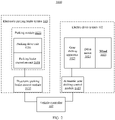
- the new energy vehicle 1000 includes a power supply system 101, an electric drive system 102, an electronic parking brake (EPB) system 103, and a vehicle control unit (VCU) 107. It may be understood that the new energy vehicle 1000 may further include another necessary or unnecessary structure, component, and the like, for example, an auxiliary system. Details are not described herein.
- the power supply system 101 includes a battery power supply, an energy management system, a charging controller, and the like, and is configured to provide electric energy.
- the electric drive system 102 is configured to efficiently convert electric energy stored in the battery power supply of the power supply system 101 into kinetic energy of the new energy vehicle 1000.
- the electric drive system 102 includes a drive motor 1021, a gear shifting apparatus 1023, a wheel 1025, and an automatic gear shifting control module 1027.
- the drive motor 1021 is connected to the wheel 1025 by using the gear shifting apparatus 1023 for power transmission.
- the automatic gear shifting control module (TCU) 1027 is configured to control the gear shifting apparatus 1023. Through use of the automatic gear shifting control module 1027, the gear shifting apparatus 1023 can change values and directions of torque and a rotation speed, to change a transmission ratio of the gear shifting apparatus 1023, that is, implement gear shifting, to change the speed and change the torque.
- the gear shifting apparatus 1023 includes a self-locking state and a non-self-locking state. When the gear shifting apparatus 1023 is in the self-locking state, the gear shifting apparatus 1023 cannot transmit power of the drive motor 1021 to the wheel 1025. When the gear shifting apparatus 1023 is in the non-self-locking state, the gear shifting apparatus 1023 can transmit power of the drive motor 1021 to the wheel 1025.
- the electric drive system 102 may further include a central control unit, a drive controller, and the like.
- the electronic parking brake system 103 is configured to provide braking force for the wheel 1025, to implement electronic parking.
- the electronic parking brake system 103 includes a parking module 1031 and an electronic parking brake control module 1035.
- there is at least one electronic parking brake control module 1035 there is at least one parking module 1031, and each parking module 1031 is correspondingly communicatively connected to one electronic parking brake control module 1035, to improve control precision and control efficiency.
- the parking module 1031 includes a parking drive unit 1036 and a parking brake execution unit 1038.
- the parking drive unit 1036 is configured to provide power for the parking brake execution unit 1038.
- the parking brake execution unit 1038 is configured to provide parking braking force for the wheel 1025.
- the parking brake execution unit 1038 may clamp or release the wheel 1025.
- the parking drive unit 1036 includes a drive apparatus such as a motor.
- the vehicle controller 107 is a core control component of the new energy vehicle 1000, and undertakes functions such as data exchange and management, fault diagnosis, safety monitoring, and driver intention parsing of each system of the new energy vehicle 1000.
- the vehicle controller 107 is communicatively connected to the power supply system 101, the electric drive system 102, the electronic parking brake system 103, and the like.
- the vehicle controller 107 may include one or more processors.
- the processor may include one or more processors (logic circuits) that provide an information processing capability in the new energy vehicle 1000.
- the processor may provide one or more computing functions for the new energy vehicle 1000.
- the processor may send a command signal to one or more components of the new energy vehicle 1000 to manipulate the new energy vehicle 1000.
- the processor may include a memory, such as a random access storage device (RAM), a flash memory, or another suitable type of storage device, such as a non-transient computer-readable memory.
- the memory of the processor may include an executable instruction and data that may be accessed by the one or more processors of the processor.
- the processor may include one or more dynamic random access memory (DRAM) modules, such as a double data rate synchronous dynamic random access memory (DDR SDRAM).
- DDR SDRAM double data rate synchronous dynamic random access memory
- the processor may include a digital signal processor (DSP).
- DSP digital signal processor
- the processor may include an application-specific integrated circuit (ASIC).
- the vehicle controller 107 is configured to control the electric drive system 102 and the electronic parking brake system 103 according to a driving instruction.
- the driving instruction includes a brake instruction, a park instruction, an unpark instruction, and the like.
- the new energy vehicle 1000 further includes a driving braking system 108 configured to perform driving braking.
- the driving braking system 108 includes a brake pedal (not shown in the figure), a sensor disposed on the brake pedal, and a brake execution unit.
- a user (such as a driver) may perform a braking operation by depressing the brake pedal.
- the sensor on the brake pedal generates a brake instruction in response to the braking operation of the user.
- the vehicle controller 107 sends a braking signal to the drive motor 1021 according to the brake instruction.
- the drive motor 1021 stops rotating based on the braking signal, the brake execution unit brakes the wheel 1025, the wheel 1025 stops rotating, and the new energy vehicle 1000 parks.
- the new energy vehicle 1000 further includes a sensing system (not shown in the figure).
- the vehicle controller 107 of the new energy vehicle 1000 may also park after performing parsing based on information and data collected by the sensing system of the new energy vehicle 1000. For example, when determining, based on the information collected by the sensing system, that an emergency (such as a suddenly burst pedestrian) occurs in a driving direction, the vehicle controller 107 controls the new energy vehicle 1000 to automatically park.
- the electronic parking brake system 103 further includes a parking button that is communicatively connected to the vehicle controller 107.
- the user may press the parking button to perform the parking operation, and the parking button generates a park instruction in response to the parking operation of the user.
- the vehicle controller 107 sends a parking signal to the electronic parking brake control module 1035 and the automatic gear shifting control module 1027 according to the park instruction.
- the electronic parking brake control module 1035 controls, based on the parking signal, the parking drive unit 1036 to drive the parking brake execution unit 1038 to clamp the wheel 1025, to implement an electronic parking brake function.
- the user is not limited to performing the parking operation by using the parking button, and the user may perform the parking operation on the new energy vehicle 1000 by using another device in another manner.
- the automatic gear shifting control module 1027 controls, based on the parking signal, the gear shifting apparatus 1023 to enter the self-locking state, so that the wheel 1025 cannot move, and an electronic parking function of the gear shifting apparatus 1023 is implemented. Therefore, dual insurance is provided for the new energy vehicle 1000 when parking. Because there is no need to add an additional parking structure, and an additional electronic parking function is implemented by using the gear shifting apparatus 1023, space occupied by the electronic parking brake system 103 is reduced, and lightweight development of the new energy vehicle 1000 is facilitated.
- the new energy vehicle 1000 further includes a sensing system (not shown in the figure).
- the vehicle controller 107 of the new energy vehicle 1000 may also automatically park after performing parsing based on information and data collected by the sensing system of the new energy vehicle 1000.
- the user When the new energy vehicle 1000 needs to unpark, the user performs an unparking operation on the new energy vehicle 1000.
- the user may perform the unparking operation by pressing the parking button, and the parking button generates an unpark instruction in response to the unparking operation of the user.
- the vehicle controller 107 sends an unparking signal to the electronic parking brake control module 1035 and the automatic gear shifting control module 1027 according to the unpark instruction.
- the electronic parking brake control module 1035 controls, based on the unparking signal, the parking drive unit 1036 to drive the parking brake execution unit 1038 to release the wheel 1025, so that the new energy vehicle 1000 unparks.
- the gear shifting apparatus 1023 includes a primary power transmission unit 12, a secondary power transmission unit 13, an intermediate shaft 141, an intermediate shaft gear 143, a first clutch unit 15, a second clutch unit 16, a third clutch unit 17, and a differential unit 19.
- the drive motor 1021 includes a drive body 1022 and an input shaft 1024.
- the drive body 1022 is configured to drive the input shaft 1024 to rotate.
- the primary power transmission unit 12 is connected to the input shaft 1024 for power transmission.
- the secondary power transmission unit 13 is connected to the input shaft 1024 for power transmission.
- the intermediate shaft gear 143 is fixedly sleeved on the intermediate shaft 141.
- the first clutch unit 15 is disposed between the intermediate shaft 141 and the primary power transmission unit 12, and the first clutch unit 15 is configured to achieve or break power transmission between the intermediate shaft 141 and the primary power transmission unit 12.
- the second clutch unit 16 is disposed between the intermediate shaft 141 and the secondary power transmission unit 13, and the second clutch unit 16 is configured to achieve or break power transmission between the intermediate shaft 141 and the secondary power transmission unit 13.
- the third clutch unit is disposed between the intermediate shaft gear 143 and the primary power transmission unit 12, and is configured to achieve or break power transmission between the intermediate shaft gear 143 and the primary power transmission unit 12.
- the intermediate shaft 141 cannot rotate, and the gear shifting apparatus 1023 cannot transmit power of the drive motor 1021 to the wheel 1025.
- the intermediate shaft 141 can rotate, and the gear shifting apparatus 1023 can transmit power of the drive motor 1021 to the wheel 1025.
- the automatic gear shifting control module 1027 receives the parking signal, the automatic gear shifting control module 1027 controls the gear shifting apparatus 1023 to enter the self-locking state.
- the automatic gear shifting control module 1027 receives the unparking signal
- the automatic gear shifting control module 1027 controls the gear shifting apparatus 1023 to enter the non-self-locking state.
- the gear shifting apparatus 1023 when the first clutch unit 15 achieves power transmission between the intermediate shaft 141 and the primary power transmission unit 12, the second clutch unit 16 achieves power transmission between the intermediate shaft 141 and the secondary power transmission unit 12, and the third clutch unit 17 achieves power transmission between the intermediate shaft gear 143 and the primary power transmission unit 12, a transmission ratio obtained when the third clutch unit 17 is combined with the intermediate shaft gear 143 is different from a transmission ratio obtained when the the second clutch unit 16 is combined with the intermediate shaft 141, and the gear shifting apparatus 1023 is in the self-locking state.
- the vehicle controller 107 sends a parking signal to the electronic parking brake control module 1035 and the automatic gear shifting control module 1027
- the automatic gear shifting control module 1027 controls the gear shifting apparatus 1023 to enter the self-locking state.
- the gear shifting apparatus 1023 After the gear shifting apparatus 1023 enters the self-locking state, because the intermediate shaft 141 cannot rotate, the wheel 1025 can be prevented from rotating, and therefore a possibility that the wheel 1025 rotates is reduced.
- the gear shifting apparatus 1023 is equivalent to another parking brake system of the new energy vehicle 1000, so that double insurance is provided during parking of the new energy vehicle 1000, and a possibility of occurrence of an accident is reduced.
- the gear shifting apparatus 1023 of the electric drive system 102 and the electronic parking brake system 103 of the new energy vehicle 1000 form an electronic parking brake redundant system. Therefore, while safety of the new energy vehicle 1000 is improved, a volume occupied by the electronic parking brake redundant system can be reduced, and lightweight development of the new energy vehicle 1000 is facilitated.
- the gear shifting apparatus 1023 When the first clutch unit 15 achieves power transmission between the intermediate shaft 141 and the primary power transmission unit 12, the second clutch unit 16 achieves power transmission between the intermediate shaft 141 and the secondary power transmission unit 13, and the third clutch unit 17 is separated from the intermediate shaft gear 143 to break power transmission between the intermediate shaft gear 143 and the primary power transmission unit 12, the gear shifting apparatus 1023 is in the non-self-locking state.
- the primary power transmission unit 12 includes a primary power transmission input gear 121 and a primary power transmission output gear 123.
- the primary power transmission input gear 121 is mounted on the input shaft 1024 and can rotate with the input shaft 1024. It may be understood that the primary power transmission input gear 121 may be directly mounted on the input shaft 1024, or may be indirectly connected to the input shaft 1024 by using a connection mechanism, provided that the primary power transmission input gear 121 can rotate with the input shaft 1024.
- the primary power transmission output gear 123 meshes with the primary power transmission input gear 121, and is configured to connect to the intermediate shaft 141 for power transmission. Because the primary power transmission unit 12 includes the primary power transmission input gear 121 and the primary power transmission output gear 123, flexibility of internal component layout of the gear shifting apparatus 1023 is improved, and space occupied by the gear shifting apparatus 1023 is reduced.
- the primary power transmission output gear 123 in the primary power transmission unit 12 may alternatively be omitted, and the primary power transmission input gear 121 is directly connected to a structure such as the first clutch unit 15.
- the secondary power transmission unit 13 includes a secondary power transmission input gear 131 and a secondary power transmission output gear 133.
- the secondary power transmission input gear 131 is mounted on the input shaft 1024 and can rotate with the input shaft 1024.
- the secondary power transmission output gear 133 meshes with the secondary power transmission input gear 131, and is configured to connect to the intermediate shaft 141 for power transmission. It may be understood that the secondary power transmission input gear 131 may be directly mounted on the input shaft 1024, or may be indirectly connected to the input shaft 1024 by using a connection mechanism, provided that the secondary power transmission input gear 131 can rotate with the input shaft 1024. Because the secondary power transmission unit 13 includes the secondary power transmission input gear 131 and the secondary power transmission output gear 133, flexibility of internal component layout of the gear shifting apparatus 1023 is improved, and space occupied by the gear shifting apparatus 1023 is reduced.
- the secondary power transmission output gear 133 in the secondary power transmission unit 13 may alternatively be omitted, and the secondary power transmission input gear 131 is directly connected to a structure such as the second clutch unit 16.
- An intermediate shaft unit 14 further includes a first bearing 145 and a second bearing 147.
- the intermediate shaft gear 143 is fixedly sleeved on the intermediate shaft 141, and is configured to connect to the differential unit 19.
- the primary power transmission output gear 123 is rotatably sleeved on the intermediate shaft 141.
- the first bearing 145 is disposed between the primary power transmission output gear 123 and the intermediate shaft 141, to improve smoothness of relative movement between the primary power transmission output gear 123 and the intermediate shaft 141.
- the second bearing 147 is disposed between the secondary power transmission output gear 133 and the intermediate shaft 141, to improve smoothness of relative movement between the secondary power transmission output gear 133 and the intermediate shaft 141.
- the first clutch unit 15 includes a one-way clutch.
- the one-way clutch includes an outer ring, an inner ring, and a wedge assembly between the inner ring and the outer ring.
- the one-way clutch may be braked by using a wedge or a roller.
- the outer ring is fixedly connected to the primary power transmission output gear 123, and the inner ring is fixedly connected to the intermediate shaft 141.
- the first clutch unit 15 includes a non-combined state (also referred to as a separated state) and a combined state (also referred to as a still state).
- the one-way clutch When rotating in one direction, the inner ring and the outer ring are not in contact with each other; in other words, the one-way clutch rotates freely, the one-way clutch cannot drive the intermediate shaft 141 to rotate with the primary power transmission output gear 123, and the first clutch unit 15 is in the non-combined state.
- the inner ring and the outer ring When rotating in another direction, the inner ring and the outer ring are in close contact.
- the one-way clutch may transmit high torque, and the first clutch unit 15 can drive the intermediate shaft 141 to rotate with the primary power transmission output gear 123; in other words, the primary power transmission output gear 123 can transmit power of the input shaft 1024 to the intermediate shaft 141.
- the power of the input shaft 1024 can be transmitted to the intermediate shaft 141 by using the primary power transmission output gear 123. It may be understood that a structure of the first clutch unit 15 is not limited in this application, and power transmission between the first clutch unit 15 and the intermediate shaft 141 can be achieved or broken.
- the second clutch unit 16 includes one of a friction plate clutch and an electromagnetic clutch.
- the friction plate clutch includes a driving part, a driven part, a pressing mechanism, and a manipulation mechanism.
- the driving part, the driven part, and the pressing mechanism are basic structures for ensuring that the friction plate clutch is in a combined state and can transmit power, and the manipulation mechanism of the clutch is mainly an apparatus for separating the friction plate clutch.
- the electromagnetic clutch is a friction clutch that generates pressing force by electromagnetic force.
- the electromagnetic clutch is also referred to as an electromagnetic coupling.
- the electromagnetic clutch is an electromagnetic mechanical connector that enables, by using an electromagnetic induction principle and force of friction between an internal friction plate and an external friction plate, the driven part to be combined with or separated with the driving part while the driving part does not stop rotating, and is an electric apparatus that automatically performs an operation, where the driving part and the driven part are two parts that perform rotation motion in a mechanical power transmission system.
- the second clutch unit 16 includes a non-combined state and a combined state. When the second clutch unit 16 is in the non-combined state, the second clutch unit 16 breaks power transmission between the secondary power transmission output gear 133 and the intermediate shaft 141. When the second clutch unit 16 is in the combined state, the second clutch unit 16 connects the secondary power transmission output gear 133 and the intermediate shaft 141, and the second clutch unit 16 achieves power transmission between the secondary power transmission output gear 133 and the intermediate shaft 141. It may be understood that a structure of the second clutch unit 16 is not limited in this application, and power transmission between the second clutch unit 16 and the intermediate shaft 141 can be achieved or broken.
- the third clutch unit 17 includes a third clutch 171, an actuator connecting piece 173, and an actuator 175.
- the third clutch 171 is disposed between the intermediate shaft gear 143 and the primary power transmission output gear 123 of the primary power transmission unit 12.
- the third clutch 171 is fixedly connected to the primary power transmission output gear 123.
- the actuator connecting piece 173 is connected to the actuator 175.
- the actuator 175 is configured to control axial movement of the actuator connecting piece 173 along the intermediate shaft 141, so that the third clutch 171 is combined with the intermediate shaft gear 143 or is separated from the intermediate shaft gear 143.
- the third clutch 171 includes a non-combined state and a combined state.
- the third clutch 171 is a toothed clutch.
- the third clutch 171 meshes with the intermediate shaft gear 143.
- the third clutch 171 is separated from the intermediate shaft gear 143.
- a transmission ratio obtained when the third clutch 171 is combined with the intermediate shaft gear 143 is different from a transmission ratio obtained when the second clutch unit 16 is combined with the intermediate shaft 141.
- the third clutch 171 is combined with the intermediate shaft gear 143, and the second clutch unit 16 is combined with the intermediate shaft 141.
- the actuator 175 may be an electronic button or a mechanical operating piece. It may be understood that a structure of the third clutch unit 17 is not limited in this application, and power transmission between the third clutch unit 17 and the intermediate shaft gear 143 can be achieved or broken.
- the differential unit 19 includes a main speed reducer power transmission input gear 191, a main speed reducer power transmission output gear 193, and a differential 195.
- the main speed reducer power transmission input gear 191 is sleeved on the intermediate shaft 141.
- the main speed reducer power transmission output gear 193 meshes with the main speed reducer power transmission input gear 191.
- the differential 195 is connected to the main speed reducer power transmission output gear 193 for power transmission.
- the first clutch unit 15 When the first clutch unit 15 is in the combined state, the first clutch unit 15 is connected between the primary power transmission output gear 123 and the intermediate shaft 141.
- the second clutch unit 16 When the second clutch unit 16 is in the combined state, the second clutch unit 16 is connected between the secondary power transmission output gear 133 and the intermediate shaft 141.
- the third clutch unit 17 When the third clutch unit 17 is in the non-combined state, the third clutch 171 is separated from the intermediate shaft gear 143.
- the input shaft 1024 of the drive motor 1021 rotates, and the primary power transmission output gear 123 and the secondary power transmission output gear 133 drive the intermediate shaft 141 to rotate.
- Rotation of the intermediate shaft 141 drives the main speed reducer power transmission output gear 193 and the main speed reducer power transmission input gear 191 to rotate, and the differential 195 drives the wheel 1025 to rotate, to transmit power of the drive motor 1021 to the wheel 1025.
- the intermediate shaft 141 does not rotate, the parking brake execution unit 1038 clamps the wheel 1025, and the gear shifting apparatus 1023 implements self-locking. Therefore, double insurance is provided during parking of the new energy vehicle 1000.
- gear shifting apparatus 1023 is not limited to being applied to the new energy vehicle 1000 in this application, and may also be applied to another device or apparatus, for example, a device such as a robot.
- a structure of a new energy vehicle 1000 provided in a second implementation of this application is basically similar to a structure of the new energy vehicle provided in the first implementation. Differences lie in that there are two parking modules 1031 and one electronic parking brake control module 1035, and parking drive units 1036 in both the two parking modules 1031 are communicatively connected to the electronic parking brake control module 1035. Because the two parking modules 1031 share one electronic parking brake control module 1035, space occupied by the new energy vehicle 1000 is reduced, and costs are reduced.
- the expression “and/or” includes any and all combinations of listed associated words.
- the expression “A and/or B” may include A, may include B, or may include both A and B.
- first and second may modify each element.
- the element is not limited by the foregoing expression.
- the foregoing expression does not limit a sequence and/or importance of the elements.
- the foregoing expression is merely used to distinguish one element from another.
- first user equipment and second user equipment indicate different user equipment, although both the first user equipment and the second user equipment are user equipment.
- a first element may be referred to as a second element, and similarly, a second element may be referred to as a first element.
Applications Claiming Priority (1)
| Application Number | Priority Date | Filing Date | Title |
|---|---|---|---|
| CN202110924627.6A CN113757321B (zh) | 2021-08-12 | 2021-08-12 | 变速装置、电力驱动系统及新能源汽车 |
Publications (1)
| Publication Number | Publication Date |
|---|---|
| EP4134572A1 true EP4134572A1 (de) | 2023-02-15 |
Family
ID=78789149
Family Applications (1)
| Application Number | Title | Priority Date | Filing Date |
|---|---|---|---|
| EP22189674.9A Pending EP4134572A1 (de) | 2021-08-12 | 2022-08-10 | Getriebeschaltvorrichtung, elektrisches antriebssystem und fahrzeug mit neuer energie |
Country Status (3)
| Country | Link |
|---|---|
| US (1) | US11796052B2 (de) |
| EP (1) | EP4134572A1 (de) |
| CN (1) | CN113757321B (de) |
Citations (2)
| Publication number | Priority date | Publication date | Assignee | Title |
|---|---|---|---|---|
| DE102012015863A1 (de) * | 2012-08-06 | 2014-05-15 | Getrag Getriebe- Und Zahnradfabrik Hermann Hagenmeyer Gmbh & Cie Kg | Stufengetriebe für ein Kraftfahrzeug |
| DE102020202788B3 (de) * | 2020-03-04 | 2021-04-01 | Magna Pt B.V. & Co. Kg | Antriebsstrang für ein Fahrzeug sowie ein Verfahren zum Betreiben eines Antriebsstrangs mit Zweiganggetriebe |
Family Cites Families (14)
| Publication number | Priority date | Publication date | Assignee | Title |
|---|---|---|---|---|
| US4534236A (en) * | 1983-03-15 | 1985-08-13 | Honda Giken Kogyo Kabushiki Kaisha | Vibration and noise reduction means for a transmission vehicle |
| DE102012007061B4 (de) * | 2012-04-02 | 2015-12-31 | Getrag Getriebe- Und Zahnradfabrik Hermann Hagenmeyer Gmbh & Cie Kg | Parksperrenanordnung und Kraftfahrzeuggetriebe |
| US10844935B2 (en) * | 2014-07-18 | 2020-11-24 | Uvic Industry Partnerships Inc. | Electric drive system with a novel dual-clutch transmission |
| KR101836659B1 (ko) * | 2016-06-30 | 2018-03-09 | 현대자동차주식회사 | 하이브리드 차량용 변속기 |
| CN205896146U (zh) * | 2016-08-16 | 2017-01-18 | 河北工业大学 | 一种电动汽车变速器 |
| CN109941244B (zh) * | 2017-12-20 | 2020-12-11 | 广州汽车集团股份有限公司 | 电子驻车控制方法、装置、可读存储介质和计算机设备 |
| US11207962B2 (en) * | 2018-02-02 | 2021-12-28 | Dana Automotive Systems Group, Llc | Electric drive axle with multi-speed gearbox |
| CN208931324U (zh) | 2018-09-27 | 2019-06-04 | 芜湖伯特利汽车安全系统股份有限公司 | 一种具有双控独立控制功能的制动系统 |
| CN109281997A (zh) * | 2018-11-07 | 2019-01-29 | 柳州惠林科技有限责任公司 | 一种无倒挡第二齿轮单向传动两挡自动变速器 |
| CN110513445B (zh) * | 2019-08-23 | 2023-11-03 | 吴有智 | 电动车变速器 |
| DE102019217154A1 (de) * | 2019-11-07 | 2021-05-12 | Zf Friedrichshafen Ag | Elektrischer Antrieb für ein Fahrzeug |
| CN114508568A (zh) * | 2020-11-17 | 2022-05-17 | 华为数字能源技术有限公司 | 电动车的两档变速器及电动车 |
| CN113043841B (zh) * | 2021-03-26 | 2022-05-13 | 华为数字能源技术有限公司 | 两档传递系统及车辆 |
| CN112923044A (zh) * | 2021-04-02 | 2021-06-08 | 海马汽车有限公司 | 一种变速器动力传动系统、变速器及车辆 |
-
2021
- 2021-08-12 CN CN202110924627.6A patent/CN113757321B/zh active Active
-
2022
- 2022-08-10 EP EP22189674.9A patent/EP4134572A1/de active Pending
- 2022-08-11 US US17/886,022 patent/US11796052B2/en active Active
Patent Citations (2)
| Publication number | Priority date | Publication date | Assignee | Title |
|---|---|---|---|---|
| DE102012015863A1 (de) * | 2012-08-06 | 2014-05-15 | Getrag Getriebe- Und Zahnradfabrik Hermann Hagenmeyer Gmbh & Cie Kg | Stufengetriebe für ein Kraftfahrzeug |
| DE102020202788B3 (de) * | 2020-03-04 | 2021-04-01 | Magna Pt B.V. & Co. Kg | Antriebsstrang für ein Fahrzeug sowie ein Verfahren zum Betreiben eines Antriebsstrangs mit Zweiganggetriebe |
Also Published As
| Publication number | Publication date |
|---|---|
| CN113757321A (zh) | 2021-12-07 |
| US20220381337A1 (en) | 2022-12-01 |
| CN113757321B (zh) | 2023-09-22 |
| US11796052B2 (en) | 2023-10-24 |
Similar Documents
| Publication | Publication Date | Title |
|---|---|---|
| JP6209297B1 (ja) | 電気車両用二速トランスアクスル | |
| JP5133935B2 (ja) | パラレル式ハイブリッド車の動力伝達機構 | |
| KR20180125240A (ko) | 전자식 주차 브레이크 | |
| CN109624957A (zh) | 一种具有新型耦合方式的集成式电动助力制动系统 | |
| CN106402205A (zh) | 汽车电子机械制动系统轮边自供电式制动执行机构 | |
| CN106347339A (zh) | 汽车电子机械制动系统自供电式双电机制动执行机构 | |
| DE102010046286A1 (de) | Regeneratives Bremssystem | |
| WO2022133899A1 (zh) | 一种液压装置、制动装置、制动系统及制动控制方法 | |
| CN114572166B (zh) | 一种集成行车和驻车制动的制动装置、车辆 | |
| US4276951A (en) | Vehicular energy storing means and system | |
| CN112644445A (zh) | 一种基于ehb和esc双路控制的电子驻车制动系统 | |
| EP4134572A1 (de) | Getriebeschaltvorrichtung, elektrisches antriebssystem und fahrzeug mit neuer energie | |
| JP2010030362A (ja) | 車両用動力伝達装置 | |
| CN209290171U (zh) | 一种电动车后桥驱动系统 | |
| KR101294126B1 (ko) | 회생 제동 시스템 | |
| CN111038458A (zh) | 一种汽车刹车蓄能助力启动装置 | |
| JP4556650B2 (ja) | 車両用ブレーキ装置 | |
| JP5185971B2 (ja) | ブレーキペダル機構 | |
| CN212125092U (zh) | 一种具有电子机械制动机构的车辆 | |
| JP2007276725A (ja) | 車両用ブレーキ装置 | |
| JP6950251B2 (ja) | 車両の駆動システム | |
| CN111623063A (zh) | 一种电控制动器 | |
| CN216734243U (zh) | 一种电子机械制动系统及车辆 | |
| CN220314973U (zh) | 一种可用于电子机械制动的制动装置、制动系统和车辆 | |
| CN219154246U (zh) | 一种新能源汽车刹车失灵的应急装置 |
Legal Events
| Date | Code | Title | Description |
|---|---|---|---|
| PUAI | Public reference made under article 153(3) epc to a published international application that has entered the european phase |
Free format text: ORIGINAL CODE: 0009012 |
|
| STAA | Information on the status of an ep patent application or granted ep patent |
Free format text: STATUS: REQUEST FOR EXAMINATION WAS MADE |
|
| 17P | Request for examination filed |
Effective date: 20220810 |
|
| AK | Designated contracting states |
Kind code of ref document: A1 Designated state(s): AL AT BE BG CH CY CZ DE DK EE ES FI FR GB GR HR HU IE IS IT LI LT LU LV MC MK MT NL NO PL PT RO RS SE SI SK SM TR |
|
| STAA | Information on the status of an ep patent application or granted ep patent |
Free format text: STATUS: EXAMINATION IS IN PROGRESS |
|
| 17Q | First examination report despatched |
Effective date: 20230724 |
|
| RIC1 | Information provided on ipc code assigned before grant |
Ipc: B60K 1/00 20060101ALN20240119BHEP Ipc: F16H 61/00 20060101AFI20240119BHEP |
|
| GRAP | Despatch of communication of intention to grant a patent |
Free format text: ORIGINAL CODE: EPIDOSNIGR1 |
|
| STAA | Information on the status of an ep patent application or granted ep patent |
Free format text: STATUS: GRANT OF PATENT IS INTENDED |
|
| INTG | Intention to grant announced |
Effective date: 20240304 |