EP4134518B1 - Verfahren zur herstellung von kühlbohrungen in einer beschichteten komponente eines turbinentriebwerks - Google Patents
Verfahren zur herstellung von kühlbohrungen in einer beschichteten komponente eines turbinentriebwerks Download PDFInfo
- Publication number
- EP4134518B1 EP4134518B1 EP22190408.9A EP22190408A EP4134518B1 EP 4134518 B1 EP4134518 B1 EP 4134518B1 EP 22190408 A EP22190408 A EP 22190408A EP 4134518 B1 EP4134518 B1 EP 4134518B1
- Authority
- EP
- European Patent Office
- Prior art keywords
- section
- component
- locating feature
- substrate
- preform
- Prior art date
- Legal status (The legal status is an assumption and is not a legal conclusion. Google has not performed a legal analysis and makes no representation as to the accuracy of the status listed.)
- Active
Links
Images




Classifications
-
- C—CHEMISTRY; METALLURGY
- C23—COATING METALLIC MATERIAL; COATING MATERIAL WITH METALLIC MATERIAL; CHEMICAL SURFACE TREATMENT; DIFFUSION TREATMENT OF METALLIC MATERIAL; COATING BY VACUUM EVAPORATION, BY SPUTTERING, BY ION IMPLANTATION OR BY CHEMICAL VAPOUR DEPOSITION, IN GENERAL; INHIBITING CORROSION OF METALLIC MATERIAL OR INCRUSTATION IN GENERAL
- C23C—COATING METALLIC MATERIAL; COATING MATERIAL WITH METALLIC MATERIAL; SURFACE TREATMENT OF METALLIC MATERIAL BY DIFFUSION INTO THE SURFACE, BY CHEMICAL CONVERSION OR SUBSTITUTION; COATING BY VACUUM EVAPORATION, BY SPUTTERING, BY ION IMPLANTATION OR BY CHEMICAL VAPOUR DEPOSITION, IN GENERAL
- C23C28/00—Coating for obtaining at least two superposed coatings either by methods not provided for in a single one of groups C23C2/00 - C23C26/00 or by combinations of methods provided for in subclasses C23C and C25C or C25D
- C23C28/30—Coatings combining at least one metallic layer and at least one inorganic non-metallic layer
- C23C28/34—Coatings combining at least one metallic layer and at least one inorganic non-metallic layer including at least one inorganic non-metallic material layer, e.g. metal carbide, nitride, boride, silicide layer and their mixtures, enamels, phosphates and sulphates
-
- F—MECHANICAL ENGINEERING; LIGHTING; HEATING; WEAPONS; BLASTING
- F01—MACHINES OR ENGINES IN GENERAL; ENGINE PLANTS IN GENERAL; STEAM ENGINES
- F01D—NON-POSITIVE DISPLACEMENT MACHINES OR ENGINES, e.g. STEAM TURBINES
- F01D5/00—Blades; Blade-carrying members; Heating, heat-insulating, cooling or antivibration means on the blades or the members
- F01D5/12—Blades
- F01D5/14—Form or construction
- F01D5/18—Hollow blades, i.e. blades with cooling or heating channels or cavities; Heating, heat-insulating or cooling means on blades
- F01D5/186—Film cooling
-
- F—MECHANICAL ENGINEERING; LIGHTING; HEATING; WEAPONS; BLASTING
- F01—MACHINES OR ENGINES IN GENERAL; ENGINE PLANTS IN GENERAL; STEAM ENGINES
- F01D—NON-POSITIVE DISPLACEMENT MACHINES OR ENGINES, e.g. STEAM TURBINES
- F01D5/00—Blades; Blade-carrying members; Heating, heat-insulating, cooling or antivibration means on the blades or the members
- F01D5/12—Blades
- F01D5/28—Selecting particular materials; Particular measures relating thereto; Measures against erosion or corrosion
- F01D5/288—Protective coatings for blades
-
- F—MECHANICAL ENGINEERING; LIGHTING; HEATING; WEAPONS; BLASTING
- F01—MACHINES OR ENGINES IN GENERAL; ENGINE PLANTS IN GENERAL; STEAM ENGINES
- F01D—NON-POSITIVE DISPLACEMENT MACHINES OR ENGINES, e.g. STEAM TURBINES
- F01D9/00—Stators
- F01D9/02—Nozzles; Nozzle boxes; Stator blades; Guide conduits, e.g. individual nozzles
- F01D9/023—Transition ducts between combustor cans and first stage of the turbine in gas-turbine engines; their cooling or sealings
-
- F—MECHANICAL ENGINEERING; LIGHTING; HEATING; WEAPONS; BLASTING
- F01—MACHINES OR ENGINES IN GENERAL; ENGINE PLANTS IN GENERAL; STEAM ENGINES
- F01D—NON-POSITIVE DISPLACEMENT MACHINES OR ENGINES, e.g. STEAM TURBINES
- F01D9/00—Stators
- F01D9/06—Fluid supply conduits to nozzles or the like
- F01D9/065—Fluid supply or removal conduits traversing the working fluid flow, e.g. for lubrication-, cooling-, or sealing fluids
-
- F—MECHANICAL ENGINEERING; LIGHTING; HEATING; WEAPONS; BLASTING
- F02—COMBUSTION ENGINES; HOT-GAS OR COMBUSTION-PRODUCT ENGINE PLANTS
- F02K—JET-PROPULSION PLANTS
- F02K1/00—Plants characterised by the form or arrangement of the jet pipe or nozzle; Jet pipes or nozzles peculiar thereto
- F02K1/78—Other construction of jet pipes
- F02K1/82—Jet pipe walls, e.g. liners
- F02K1/822—Heat insulating structures or liners, cooling arrangements, e.g. post combustion liners; Infrared radiation suppressors
-
- F—MECHANICAL ENGINEERING; LIGHTING; HEATING; WEAPONS; BLASTING
- F23—COMBUSTION APPARATUS; COMBUSTION PROCESSES
- F23R—GENERATING COMBUSTION PRODUCTS OF HIGH PRESSURE OR HIGH VELOCITY, e.g. GAS-TURBINE COMBUSTION CHAMBERS
- F23R3/00—Continuous combustion chambers using liquid or gaseous fuel
- F23R3/002—Wall structures
-
- F—MECHANICAL ENGINEERING; LIGHTING; HEATING; WEAPONS; BLASTING
- F23—COMBUSTION APPARATUS; COMBUSTION PROCESSES
- F23R—GENERATING COMBUSTION PRODUCTS OF HIGH PRESSURE OR HIGH VELOCITY, e.g. GAS-TURBINE COMBUSTION CHAMBERS
- F23R3/00—Continuous combustion chambers using liquid or gaseous fuel
- F23R3/02—Continuous combustion chambers using liquid or gaseous fuel characterised by the air-flow or gas-flow configuration
- F23R3/04—Air inlet arrangements
- F23R3/06—Arrangement of apertures along the flame tube
-
- G—PHYSICS
- G01—MEASURING; TESTING
- G01N—INVESTIGATING OR ANALYSING MATERIALS BY DETERMINING THEIR CHEMICAL OR PHYSICAL PROPERTIES
- G01N22/00—Investigating or analysing materials by the use of microwaves or radio waves, i.e. electromagnetic waves with a wavelength of one millimetre or more
-
- F—MECHANICAL ENGINEERING; LIGHTING; HEATING; WEAPONS; BLASTING
- F05—INDEXING SCHEMES RELATING TO ENGINES OR PUMPS IN VARIOUS SUBCLASSES OF CLASSES F01-F04
- F05D—INDEXING SCHEME FOR ASPECTS RELATING TO NON-POSITIVE-DISPLACEMENT MACHINES OR ENGINES, GAS-TURBINES OR JET-PROPULSION PLANTS
- F05D2230/00—Manufacture
- F05D2230/10—Manufacture by removing material
- F05D2230/12—Manufacture by removing material by spark erosion methods
-
- F—MECHANICAL ENGINEERING; LIGHTING; HEATING; WEAPONS; BLASTING
- F05—INDEXING SCHEMES RELATING TO ENGINES OR PUMPS IN VARIOUS SUBCLASSES OF CLASSES F01-F04
- F05D—INDEXING SCHEME FOR ASPECTS RELATING TO NON-POSITIVE-DISPLACEMENT MACHINES OR ENGINES, GAS-TURBINES OR JET-PROPULSION PLANTS
- F05D2230/00—Manufacture
- F05D2230/10—Manufacture by removing material
- F05D2230/13—Manufacture by removing material using lasers
-
- F—MECHANICAL ENGINEERING; LIGHTING; HEATING; WEAPONS; BLASTING
- F05—INDEXING SCHEMES RELATING TO ENGINES OR PUMPS IN VARIOUS SUBCLASSES OF CLASSES F01-F04
- F05D—INDEXING SCHEME FOR ASPECTS RELATING TO NON-POSITIVE-DISPLACEMENT MACHINES OR ENGINES, GAS-TURBINES OR JET-PROPULSION PLANTS
- F05D2230/00—Manufacture
- F05D2230/90—Coating; Surface treatment
-
- F—MECHANICAL ENGINEERING; LIGHTING; HEATING; WEAPONS; BLASTING
- F05—INDEXING SCHEMES RELATING TO ENGINES OR PUMPS IN VARIOUS SUBCLASSES OF CLASSES F01-F04
- F05D—INDEXING SCHEME FOR ASPECTS RELATING TO NON-POSITIVE-DISPLACEMENT MACHINES OR ENGINES, GAS-TURBINES OR JET-PROPULSION PLANTS
- F05D2240/00—Components
- F05D2240/10—Stators
- F05D2240/11—Shroud seal segments
-
- F—MECHANICAL ENGINEERING; LIGHTING; HEATING; WEAPONS; BLASTING
- F05—INDEXING SCHEMES RELATING TO ENGINES OR PUMPS IN VARIOUS SUBCLASSES OF CLASSES F01-F04
- F05D—INDEXING SCHEME FOR ASPECTS RELATING TO NON-POSITIVE-DISPLACEMENT MACHINES OR ENGINES, GAS-TURBINES OR JET-PROPULSION PLANTS
- F05D2240/00—Components
- F05D2240/80—Platforms for stationary or moving blades
- F05D2240/81—Cooled platforms
-
- F—MECHANICAL ENGINEERING; LIGHTING; HEATING; WEAPONS; BLASTING
- F05—INDEXING SCHEMES RELATING TO ENGINES OR PUMPS IN VARIOUS SUBCLASSES OF CLASSES F01-F04
- F05D—INDEXING SCHEME FOR ASPECTS RELATING TO NON-POSITIVE-DISPLACEMENT MACHINES OR ENGINES, GAS-TURBINES OR JET-PROPULSION PLANTS
- F05D2250/00—Geometry
- F05D2250/30—Arrangement of components
- F05D2250/32—Arrangement of components according to their shape
- F05D2250/324—Arrangement of components according to their shape divergent
-
- F—MECHANICAL ENGINEERING; LIGHTING; HEATING; WEAPONS; BLASTING
- F05—INDEXING SCHEMES RELATING TO ENGINES OR PUMPS IN VARIOUS SUBCLASSES OF CLASSES F01-F04
- F05D—INDEXING SCHEME FOR ASPECTS RELATING TO NON-POSITIVE-DISPLACEMENT MACHINES OR ENGINES, GAS-TURBINES OR JET-PROPULSION PLANTS
- F05D2260/00—Function
- F05D2260/20—Heat transfer, e.g. cooling
- F05D2260/202—Heat transfer, e.g. cooling by film cooling
-
- F—MECHANICAL ENGINEERING; LIGHTING; HEATING; WEAPONS; BLASTING
- F23—COMBUSTION APPARATUS; COMBUSTION PROCESSES
- F23R—GENERATING COMBUSTION PRODUCTS OF HIGH PRESSURE OR HIGH VELOCITY, e.g. GAS-TURBINE COMBUSTION CHAMBERS
- F23R2900/00—Special features of, or arrangements for continuous combustion chambers; Combustion processes therefor
- F23R2900/00018—Manufacturing combustion chamber liners or subparts
-
- F—MECHANICAL ENGINEERING; LIGHTING; HEATING; WEAPONS; BLASTING
- F23—COMBUSTION APPARATUS; COMBUSTION PROCESSES
- F23R—GENERATING COMBUSTION PRODUCTS OF HIGH PRESSURE OR HIGH VELOCITY, e.g. GAS-TURBINE COMBUSTION CHAMBERS
- F23R2900/00—Special features of, or arrangements for continuous combustion chambers; Combustion processes therefor
- F23R2900/03042—Film cooled combustion chamber walls or domes
Definitions
- the cooling aperture may include a first section and a second section.
- the forming of the cooling aperture may include: forming the first section in at least the exterior (e.g. outer) coating using a first machining process; and forming the second section in the substrate using a second machining process that is different than the first machining process.
- the substrate may be configured from or otherwise include metal.
- the outer coating may be configured from or otherwise include ceramic.
- the cooling aperture may be configured as a single lobed diffuser section.
- the cooling aperture may be configured as a multi-lobed diffuser section.
- the preform component may be configured as or otherwise include a preform of an airfoil for the turbine engine.
- the preform component may be configured as or otherwise include a preform of a flowpath wall for the turbine engine.
- the present invention may include any one or more of the individual features disclosed above and/or below alone or in any combination thereof.
- the present invention includes methods for manufacturing fluid cooled components of a gas turbine engine.
- the turbine engine may be described below as a turbofan turbine engine.
- the present invention is not limited to such an exemplary gas turbine engine.
- the turbine engine for example, may alternatively be configured as a turbojet turbine engine, a turboprop turbine engine, a turboshaft turbine engine, a propfan turbine engine, a pusher fan turbine engine or an auxiliary power unit (APU) turbine engine.
- the turbine engine may be configured as a geared turbine engine or a direct drive turbine engine.
- the present invention is also not limited to aircraft applications.
- the turbine engine for example, may alternatively be configured as a ground-based industrial turbine engine for power generation, or any other type of turbine engine which utilizes fluid cooled components.
- bypass air During operation, air enters the turbine engine 20 through the airflow inlet 24. This air is directed through the fan section 28 and into a core flowpath 54 and a bypass flowpath 56.
- the core flowpath 54 extends sequentially through the engine sections 29A-32.
- the air within the core flowpath 54 may be referred to as "core air”.
- the bypass flowpath 56 extends through a bypass duct, which bypasses the engine core.
- the air within the bypass flowpath 56 may be referred to as "bypass air”.
- the rotation of the LPT rotor 44 also drives rotation of the fan rotor 40, which propels bypass air through and out of the bypass flowpath 56.
- the propulsion of the bypass air may account for a majority of thrust generated by the turbine engine 20, e.g., more than seventy-five percent (75%) of engine thrust.
- the turbine engine 20 of the present disclosure is not limited to the foregoing exemplary thrust ratio.
- fluid cooled components 60 include flowpath walls such as, but not limited to, a combustor wall (e.g., 60F), an exhaust duct wall (e.g., 60E), a shroud or other flowpath wall (e.g., 60G), a rotor blade platform and a stator vane platform.
- flowpath walls such as, but not limited to, a combustor wall (e.g., 60F), an exhaust duct wall (e.g., 60E), a shroud or other flowpath wall (e.g., 60G), a rotor blade platform and a stator vane platform.
- flowpath walls such as, but not limited to, a combustor wall (e.g., 60F), an exhaust duct wall (e.g., 60E), a shroud or other flowpath wall (e.g., 60G), a rotor blade platform and a stator vane platform.
- various other fluid cooled components may be included in the turbine engine 20,
- FIG. 2 illustrates a portion of one of the fluid cooled components 60 within the turbine engine 20.
- This fluid cooled component 60 has a component wall 62 (e.g., a sidewall or an endwall) configured with one or more cooling apertures 64.
- the component wall 62 has a thickness 66 that extends vertically (e.g., along a z-axis) between and to a first surface 68 and a second surface 70.
- the component first surface 68 may be configured as an interior and/or a cold side surface of the component wall 62.
- the component first surface 68 may at least partially form a peripheral boundary of a cooling fluid volume 72 (e.g., a cavity or a passage) along the component wall 62.
- the component first surface 68 may thereby be subject to relatively cool fluid (e.g., cooling air) supplied to the cooling fluid volume 72.
- This cooling fluid volume 72 may be an internal volume formed within the fluid cooled component 60 where, for example, the component is an airfoil. Alternatively, the cooling fluid volume 72 may be an external volume formed external to the fluid cooled component 60 where, for example, the component is a flowpath wall.
- the component second surface 70 may be configured as an exterior and/or a hot side surface of the component wall 62. The component second surface 70, for example, may at least partially form a peripheral boundary of a portion of, for example, the core flowpath 54 along the component wall 62. The component second surface 70 may thereby be subject to relative hot fluid (e.g., combustion products) flowing through the core flowpath 54 within, for example, one of the engine sections 30-32 of FIG. 1 .
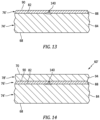
- the component wall 62 of FIG. 3 includes a component substrate 74 and one or more external component coatings 76 and 78.
- the component substrate 74 at least partially or completely forms and carries the component first surface 68.
- the component substrate 74 has a thickness 80 that extends vertically (e.g., along the z-axis) between and to the component first surface 68 and a second surface 82 of the component substrate 74.
- This substrate second surface 82 may be configured as an exterior surface of the component substrate 74 prior to being (e.g., partially or completely) covered by the one or more component coatings 76 and 78.
- the substrate thickness 80 may be greater than one-half (1/2) of the wall thickness 66.
- the substrate thickness 80 for example, may be between two-third (2/3) and four-fifths (4/5) of the wall thickness 66.
- the component substrate 74 is constructed from substrate material 84.
- This substrate material 84 may be an electrically conductive material.
- the substrate material 84 may be or otherwise include metal.
- the metal include, but are not limited to, nickel (Ni), titanium (Ti), aluminum (Al), chromium (Cr), cobalt (Co), and alloys thereof.
- the metal for example, may be a nickel or cobalt based superalloy such as, but not limited to, PWA 1484 or PWA 1429.
- the inner coating 76 may be configured as a bond coating between the component substrate 74 and the outer coating 78.
- the inner coating 76 of FIG. 3 is bonded (e.g., directly) to the substrate second surface 82.
- the inner coating 76 at least partially or completely covers the substrate second surface 82 (e.g., along an x-y plane of FIG. 2 ).
- the inner coating 76 has a thickness 86 that extends vertically (e.g., along the z-axis) between and to component substrate 74 and the outer coating 78.
- This inner coating thickness 86 may be less than one-seventh (1/7) of the wall thickness 66.
- the inner coating thickness 86 for example, may be between one-eighth (1/8) and one-fortieth (1/40) of the wall thickness 66.
- the inner coating 76 is constructed from inner coating material 88.
- This inner coating material 88 may be an electrically conductive material.
- the inner coating material 88 may be or otherwise include metal. Examples of the metal include, but are not limited to, MCrAlY and MAlCrX, where "M” is nickel (Ni), cobalt (Co), iron (Fe) or any combination thereof, and where "Y” or “X” is hafnium (Hf), yttrium (Y), silicon (Si) or any combination thereof.
- the MCrAlY and MAlCrX may be further modified with strengthening elements such as, but not limited to, tantalum (Ta), rhenium (Re), tungsten (W), molybdenum (Mo) or any combination thereof.
- strengthening elements such as, but not limited to, tantalum (Ta), rhenium (Re), tungsten (W), molybdenum (Mo) or any combination thereof.
- An example of the MCrAlY is PWA 286.
- the outer coating 78 may be configured as a protective coating for the component substrate 74 and, more generally, the fluid cooled component 60.
- the outer coating 78 may be configured as a thermal barrier layer and/or an environmental layer.
- the outer coating 78 at least partially or completely forms and carries the component second surface 70.
- the outer coating 78 of FIG. 2 is bonded (e.g., directly) to a second (e.g., exterior) surface 90 of the inner coating 76.
- the outer coating 78 at least partially or completely covers the inner coating second surface 90 as well as the underlying substrate second surface 82 (e.g., along an x-y plane of FIG. 2 ).
- the outer coating 78 has a thickness 92 that extends vertically (e.g., along the z-axis) between and to the inner coating 76 and the component second surface 70.
- This outer coating thickness 92 may be less than one-half (1/2) of the wall thickness 66.
- the outer coating thickness 92 for example, may be between one-third (1/3) and one-eighth (1/8) of the wall thickness 66.
- the outer coating thickness 92 may be greater than the inner coating thickness 86.
- the outer coating 78 is constructed from outer coating material 94.
- This outer coating material 94 may be a non-electrically conductive material.
- the outer coating material 88 may be or otherwise include ceramic. Examples of the ceramic include, but are not limited to, yttria stabilized zirconia (YSZ) and gadolinium zirconate (GdZ).
- the outer coating material 94 of the present invention is not limited to non-electrically conductive materials. In other embodiments, for example, the outer coating material 94 may be an electrically conductive material; e.g., metal.
- the outer coating 78 may be formed from a single layer of the outer coating material 94.
- the outer coating 78 may alternatively be formed from a plurality of layers of the outer coating material 94, where the outer coating material 94 within each of those outer coating layers may be the same as one another or different from one another.
- the outer coating 78 may include a thin interior layer of the YSZ and a thicker exterior later of the GdZ.
- Each of the cooling apertures 64 extends along a respective longitudinal centerline 96 between and to an inlet 98 of the respective cooling aperture 64 and an outlet 100 of the respective cooling aperture 64.
- the cooling aperture inlet 98 of FIG. 3 is located in the component first surface 68.
- the cooling aperture inlet 98 thereby fluidly couples its respective cooling aperture 64 with the cooling fluid volume 72 along the component first surface 68.
- the cooling aperture outlet 100 of FIG. 3 is located in the component second surface 70.
- the cooling aperture outlet 100 thereby fluidly couples its respective cooling aperture 64 with the core flowpath 54 along the component second surface 70.
- Each of the cooling apertures 64 may include a meter section 102 and a diffuser section 104.
- the meter section 102 is disposed at (e.g., on, adjacent or proximate) the cooling aperture inlet 98.
- the meter section 102 is configured to meter (e.g., regulate) a flow of cooling fluid flowing from the cooling fluid volume 72, through the substrate material 84, to the diffuser section 104.
- the diffuser section 104 is disposed at the cooling aperture outlet 100.
- the diffuser section 104 is configured to diffuse the cooling fluid exhausted (e.g., directed out) from the cooling aperture outlet 100 into, for example, a film for cooling a downstream portion of the component second surface 70.
- the meter section 102 of FIG. 3 extends longitudinally along the longitudinal centerline 96 within (e.g., partially into) the component substrate 74. More particularly, the meter section 102 extends longitudinally along a meter segment 106 of the longitudinal centerline 96 (e.g., a centerline of the meter section 102) from the cooling aperture inlet 98 to an outlet 108 of the meter section 102.
- the meter section outlet 108 of FIG. 3 is disposed vertically within the component substrate 74 intermediately between the component first surface 68 and the substrate second surface 82. The meter section outlet 108 of FIG. 3 is thereby vertically recessed into the component substrate 74 by a vertical distance 110 (e.g., along the z-axis).
- the longitudinal centerline 96 and its (e.g., entire) meter segment 106 of FIG. 3 are angularly offset from the component first surface 68 by an included angle 112.
- This meter segment angle 112 may be an acute angle.
- the meter segment angle 112, for example, may be between ten degrees (10°) and eighty degrees (80°); e.g., between twenty degrees (20°) and thirty degrees (30°).
- the meter section 102 has a longitudinal length 114 measured along the meter segment 106 between the cooling aperture inlet 98 and the meter section outlet 108.
- the meter section 102 has a lateral width 116 (e.g., diameter) measured along a line perpendicular to the meter section 102 of the longitudinal centerline 96.
- the meter section lateral width 116 may be different (e.g., smaller or larger) than or equal to the meter section longitudinal length 114.
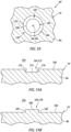
- the meter section 102 has a cross-sectional geometry when viewed, for example, in a plane perpendicular to its meter segment 106 (or the x-y plane). This meter section cross-sectional geometry may be uniform along the longitudinal length 114 of the meter section 102. Referring to FIG. 4 , the meter section cross-sectional geometry may be circular, oval, elliptical or otherwise annular in shape. The present invention, however, is not limited to such exemplary annular shapes.
- the diffuser section 104 of FIG. 3 extends longitudinally along the longitudinal centerline 96 out of the component substrate 74, through the inner coating 76 and the outer coating 78. More particularly, the diffuser section 104 of FIG. 3 extends longitudinally along a diffuser segment 118 of the longitudinal centerline 96 (e.g., a centerline of the diffuser section 104) from an inlet 120 of the diffuser section 104 (here, the same as the meter section outlet 108), through the materials 84, 88 and 94, to the cooling aperture outlet 100.
- the diffuser section inlet 120 of FIG. 3 is disposed vertically within the component substrate 74 intermediately between the component first surface 68 and the substrate second surface 82.
- the diffuser section inlet 120 of FIG. 3 is thereby vertically recessed into the component substrate 74 by the vertical distance 110 (e.g., along the z-axis).
- the longitudinal centerline 96 and its (e.g., entire) diffuser segment 118 of FIG. 3 are angularly offset from the component second surface 70 by an included angle 122.
- This diffuser segment angle 122 may be an acute angle.
- the diffuser segment angle 122 for example, may be between twenty degrees (20°) and eighty degrees (80°); e.g., between thirty-five degrees (35°) and fifty-five degrees (55°).
- the diffuser segment angle 122 of FIG. 3 is different (e.g., less) than the meter segment angle 112.
- the diffuser segment 118 may thereby be angularly offset from the meter segment 106.
- the diffuser section 104 has a longitudinal length 124 measured along the diffuser segment 118 between the diffuser section inlet 120 and the cooling aperture outlet 100. This diffuser section longitudinal length 124 may be equal to or different (e.g., less or greater) than the meter section longitudinal length 114.
- the diffuser section 104 has a lateral width 126, 128 (see FIG. 4 ) measured along a respective line perpendicular to the diffuser segment 118 of the longitudinal centerline 96.
- the diffuser section lateral width 126, 128 may be different (e.g., smaller or larger) than or equal to the diffuser section longitudinal length 124.
- the diffuser section lateral width 126, 128 of FIGS. 3 and 4 at other locations along the longitudinal centerline 96 may be greater than meter section lateral width 116. More particularly, the diffuser section 104 laterally diverges as the diffuser section 104 projects longitudinally away from the meter section 102 towards or to the cooling aperture outlet 100.
- the diffuser section 104 has a cross-sectional geometry when viewed, for example, in a plane perpendicular to its diffuser segment 118. This diffuser section cross-sectional geometry changes as the diffuser section 104 projects longitudinally away from the meter section 102, sequentially through the materials 84, 88 and 94 of FIG. 3 , to the cooling aperture outlet 100.
- the cooling aperture outlet 100 may have a complex cross-sectional geometry when viewed, for example, a plane parallel with the component second surface 70 (e.g., the x-y plane).
- This outlet cross-sectional geometry may include a (e.g., curved or straight) leading edge section 132, a (e.g., curved or straight) trailing edge section 134 and opposing (e.g., curved or straight) sidewall sections 136A and 136B (generally referred to as "136").
- Each of the sidewall sections 136 extends between and to respective ends of the leading and the trailing edge sections 132 and 134.
- a lateral width of the leading edge section 132 may be different (e.g., smaller) than a lateral width of the trailing edge section 134.
- the sidewall sections 136 may thereby generally laterally diverge away from one another as the sidewall sections 136 extend from the leading edge section 132 to the trailing edge section 134.
- the diffuser section 104 may be configured as a single lobe diffuser section. In other embodiments, referring to FIGS. 5 and 6 , the diffuser section 104 may be configured as a multi-lobe diffuser section.
- Various other single lobe and multi-lobe diffuser sections for cooling apertures 64 are known in the art, and the present invention disclosure is not limited to any particular ones thereof. Further details on various multi-lobe diffuser sections can be found in U.S. Patent No. 9,598,979 .
Landscapes
- Engineering & Computer Science (AREA)
- Chemical & Material Sciences (AREA)
- Mechanical Engineering (AREA)
- General Engineering & Computer Science (AREA)
- Physics & Mathematics (AREA)
- Combustion & Propulsion (AREA)
- Inorganic Chemistry (AREA)
- Materials Engineering (AREA)
- Immunology (AREA)
- Electromagnetism (AREA)
- Biochemistry (AREA)
- General Health & Medical Sciences (AREA)
- General Physics & Mathematics (AREA)
- Health & Medical Sciences (AREA)
- Pathology (AREA)
- Analytical Chemistry (AREA)
- Chemical Kinetics & Catalysis (AREA)
- Life Sciences & Earth Sciences (AREA)
- Metallurgy (AREA)
- Organic Chemistry (AREA)
- Fluid Mechanics (AREA)
- Turbine Rotor Nozzle Sealing (AREA)
Claims (15)
- Fertigungsverfahren für eine Komponente eines Turbinentriebwerks, umfassend:Bereitstellen (702, 704) einer Vorformkomponente (60') für das Turbinentriebwerk, wobei die Vorformkomponente ein Substrat (74') und ein Positionierungsmerkmal (140) an einer Außenfläche (82) des Substrats (74') beinhaltet;Aufbringen (708) einer Außenbeschichtung (78') über dem Substrat (74'), wobei die Außenbeschichtung (78') das Positionierungsmerkmal (140) bedeckt;Abtasten (710) mindestens eines Abschnitts der Vorformkomponente (60') und der Außenbeschichtung (78') mit einem Bildgebungssystem (158), um Abtastdaten bereitzustellen, die eine Position des Positionierungsmerkmals (140) angeben; undHerstellen einer Kühlbohrung (64) in dem Substrat (74') und der Außenbeschichtung (78') auf der Grundlage der Abtastdaten.
- Fertigungsverfahren nach Anspruch 1, wobei das Positionierungsmerkmal (140) eine Vertiefung (146) in der Außenfläche (82) des Substrats (74') umfasst.
- Fertigungsverfahren nach Anspruch 1, wobei das Positionierungsmerkmal einen Vorsprung (152) umfasst, der von der Außenfläche (82) des Substrats (74') heraus vorsteht.
- Fertigungsverfahren nach einem der vorhergehenden Ansprüche, wobei das Positionierungsmerkmal (140) während des Herstellens der Kühlbohrung (64) entfernt wird.
- Fertigungsverfahren nach einem der vorhergehenden Ansprüche, wobei das Bildgebungssystem (158) ein Mikrowellen-Bildgebungssystem umfasst.
- Fertigungsverfahren nach einem der vorhergehenden Ansprüche, ferner umfassend:
Aufbringen einer Innenbeschichtung (76') auf das Substrat (74'); wobei die Außenbeschichtung (78') auf die Innenbeschichtung (76') aufgebracht wird. - Fertigungsverfahren nach einem der vorhergehenden Ansprüche, wobeidie Kühlbohrung einen ersten Bereich (104) und einen zweiten Bereich (102) beinhaltet;das Herstellen der Kühlbohrung (64) Folgendes beinhaltet:Herstellen des ersten Bereichs (104) in mindestens der Außenbeschichtung (78') unter Verwendung eines ersten Bearbeitungsprozesses; undHerstellen des zweiten Bereichs (102) in dem Substrat (74') unter Verwendung eines zweiten Bearbeitungsprozesses, der sich von dem ersten Bearbeitungsprozess unterscheidet.
- Fertigungsverfahren nach einem der vorhergehenden Ansprüche, wobei die Kühlbohrung (64) einen Messbereich (102) und einen Diffusorbereich (104) beinhaltet.
- Fertigungsverfahren nach Anspruch 7, ferner umfassend:Herstellen eines zweiten Positionierungsmerkmals (164) an einem Ende des ersten Bereichs (104);wobei der zweite Bereich (102) basierend auf einer Position des zweiten Positionierungsmerkmals (164) hergestellt wird.
- Fertigungsverfahren nach Anspruch 9, wobei das zweite Positionierungsmerkmal (164) während des Herstellens des ersten Bereichs (104) hergestellt wird.
- Fertigungsverfahren nach einem der vorhergehenden Ansprüche, wobei:das Substrat (74') Metall umfasst; unddie Außenbeschichtung (78') Keramik umfasst.
- Fertigungsverfahren nach einem der vorhergehenden Ansprüche, wobei die Kühlbohrung (64) einen einlappigen Diffusorbereich (104) umfasst.
- Fertigungsverfahren nach einem der Ansprüche 1-11, wobei die Kühlbohrung (64) einen mehrlappigen Diffusorbereich (104) umfasst.
- Fertigungsverfahren nach einem der vorhergehenden Ansprüche, wobei die Vorformkomponente (60') eine Vorform eines Schaufelblatts (60A) für das Turbinentriebwerk umfasst.
- Fertigungsverfahren nach einem der Ansprüche 1-13, wobei die Vorformkomponente (60') eine Vorform einer Strömungswegwand (60G) für das Turbinentriebwerk umfasst.
Priority Applications (1)
| Application Number | Priority Date | Filing Date | Title |
|---|---|---|---|
| EP25187955.7A EP4606995A3 (de) | 2021-08-13 | 2022-08-15 | Verfahren zur herstellung von kühlungsöffnungen in einer beschichteten turbinenmotorkomponente |
Applications Claiming Priority (1)
| Application Number | Priority Date | Filing Date | Title |
|---|---|---|---|
| US17/401,966 US11913119B2 (en) | 2021-08-13 | 2021-08-13 | Forming cooling aperture(s) in a turbine engine component |
Related Child Applications (1)
| Application Number | Title | Priority Date | Filing Date |
|---|---|---|---|
| EP25187955.7A Division EP4606995A3 (de) | 2021-08-13 | 2022-08-15 | Verfahren zur herstellung von kühlungsöffnungen in einer beschichteten turbinenmotorkomponente |
Publications (3)
| Publication Number | Publication Date |
|---|---|
| EP4134518A2 EP4134518A2 (de) | 2023-02-15 |
| EP4134518A3 EP4134518A3 (de) | 2023-05-24 |
| EP4134518B1 true EP4134518B1 (de) | 2025-07-09 |
Family
ID=82939680
Family Applications (2)
| Application Number | Title | Priority Date | Filing Date |
|---|---|---|---|
| EP25187955.7A Pending EP4606995A3 (de) | 2021-08-13 | 2022-08-15 | Verfahren zur herstellung von kühlungsöffnungen in einer beschichteten turbinenmotorkomponente |
| EP22190408.9A Active EP4134518B1 (de) | 2021-08-13 | 2022-08-15 | Verfahren zur herstellung von kühlbohrungen in einer beschichteten komponente eines turbinentriebwerks |
Family Applications Before (1)
| Application Number | Title | Priority Date | Filing Date |
|---|---|---|---|
| EP25187955.7A Pending EP4606995A3 (de) | 2021-08-13 | 2022-08-15 | Verfahren zur herstellung von kühlungsöffnungen in einer beschichteten turbinenmotorkomponente |
Country Status (2)
| Country | Link |
|---|---|
| US (1) | US11913119B2 (de) |
| EP (2) | EP4606995A3 (de) |
Families Citing this family (1)
| Publication number | Priority date | Publication date | Assignee | Title |
|---|---|---|---|---|
| FR3151232A1 (fr) * | 2023-07-21 | 2025-01-24 | Safran Aircraft Engines | Procede de fabrication d’une aube de turbine de turbomachine |
Citations (3)
| Publication number | Priority date | Publication date | Assignee | Title |
|---|---|---|---|---|
| US6573474B1 (en) | 2000-10-18 | 2003-06-03 | Chromalloy Gas Turbine Corporation | Process for drilling holes through a thermal barrier coating |
| WO2013165509A2 (en) | 2012-02-15 | 2013-11-07 | United Technologies Corporation | Multi-lobed cooling hole |
| US20150107341A1 (en) | 2013-10-21 | 2015-04-23 | General Electric Company | Method and system for detecting surface features on turbine components |
Family Cites Families (69)
| Publication number | Priority date | Publication date | Assignee | Title |
|---|---|---|---|---|
| US4762464A (en) | 1986-11-13 | 1988-08-09 | Chromalloy Gas Turbine Corporation | Airfoil with diffused cooling holes and method and apparatus for making the same |
| EP0985802B1 (de) | 1998-09-10 | 2003-10-29 | ALSTOM (Switzerland) Ltd | Verfahren zum Ausbilden einer Filmkühlbohrung |
| US6234755B1 (en) | 1999-10-04 | 2001-05-22 | General Electric Company | Method for improving the cooling effectiveness of a gaseous coolant stream, and related articles of manufacture |
| US6368060B1 (en) | 2000-05-23 | 2002-04-09 | General Electric Company | Shaped cooling hole for an airfoil |
| US6909800B2 (en) | 2000-12-15 | 2005-06-21 | United Technologies Corporation | Process and apparatus for locating coated cooling holes on turbine vanes |
| US6420677B1 (en) | 2000-12-20 | 2002-07-16 | Chromalloy Gas Turbine Corporation | Laser machining cooling holes in gas turbine components |
| US6663919B2 (en) | 2002-03-01 | 2003-12-16 | General Electric Company | Process of removing a coating deposit from a through-hole in a component and component processed thereby |
| US7411150B2 (en) * | 2002-06-12 | 2008-08-12 | Alstom Technology Ltd. | Method of producing a composite component |
| GB2395157B (en) | 2002-11-15 | 2005-09-07 | Rolls Royce Plc | Laser driliing shaped holes |
| EP1437191A1 (de) * | 2003-01-13 | 2004-07-14 | Siemens Aktiengesellschaft | Verfahren zur Erzeugung eines Lochs |
| GB2389330B (en) | 2003-03-31 | 2004-05-05 | M J Technologies Ltd | Machining of cooling air holes in gas turbine components |
| US7041933B2 (en) | 2003-04-14 | 2006-05-09 | Meyer Tool, Inc. | Complex hole shaping |
| GB2406300A (en) | 2003-09-20 | 2005-03-30 | Rolls Royce Plc | A method of laser machining components having a protective surface coating |
| US7328580B2 (en) | 2004-06-23 | 2008-02-12 | General Electric Company | Chevron film cooled wall |
| EP1712739A1 (de) | 2005-04-12 | 2006-10-18 | Siemens Aktiengesellschaft | Bauteil mit Filmkühlloch |
| JP4752841B2 (ja) | 2005-11-01 | 2011-08-17 | 株式会社Ihi | タービン部品 |
| US7964087B2 (en) | 2007-03-22 | 2011-06-21 | General Electric Company | Methods and systems for forming cooling holes having circular inlets and non-circular outlets |
| US7820267B2 (en) | 2007-08-20 | 2010-10-26 | Honeywell International Inc. | Percussion drilled shaped through hole and method of forming |
| US20090169394A1 (en) * | 2007-12-28 | 2009-07-02 | General Electric Company | Method of forming cooling holes and turbine airfoil with hybrid-formed cooling holes |
| DE102008016026A1 (de) | 2008-03-28 | 2009-10-01 | Mtu Aero Engines Gmbh | Verfahren und Vorrichtung zum Vermessen wenigstens einer Bohrung in zumindest einer ersten Oberfläche eines Bauteils |
| US8057181B1 (en) | 2008-11-07 | 2011-11-15 | Florida Turbine Technologies, Inc. | Multiple expansion film cooling hole for turbine airfoil |
| US7997868B1 (en) | 2008-11-18 | 2011-08-16 | Florida Turbine Technologies, Inc. | Film cooling hole for turbine airfoil |
| US8245519B1 (en) | 2008-11-25 | 2012-08-21 | Florida Turbine Technologies, Inc. | Laser shaped film cooling hole |
| US8168912B1 (en) | 2009-02-19 | 2012-05-01 | Florida Turbine Technologies, Inc. | Electrode for shaped film cooling hole |
| US8319146B2 (en) | 2009-05-05 | 2012-11-27 | General Electric Company | Method and apparatus for laser cutting a trench |
| WO2011020490A1 (de) | 2009-08-17 | 2011-02-24 | Siemens Aktiengesellschaft | Verfahren zur herstellung eines asymmetrischen diffusors unter verwendung verschiedener laserstellungen |
| US8905713B2 (en) | 2010-05-28 | 2014-12-09 | General Electric Company | Articles which include chevron film cooling holes, and related processes |
| US8672613B2 (en) | 2010-08-31 | 2014-03-18 | General Electric Company | Components with conformal curved film holes and methods of manufacture |
| US20120102959A1 (en) | 2010-10-29 | 2012-05-03 | John Howard Starkweather | Substrate with shaped cooling holes and methods of manufacture |
| US9696035B2 (en) | 2010-10-29 | 2017-07-04 | General Electric Company | Method of forming a cooling hole by laser drilling |
| US20120167389A1 (en) | 2011-01-04 | 2012-07-05 | General Electric Company | Method for providing a film cooled article |
| US8814500B1 (en) | 2011-06-17 | 2014-08-26 | Florida Turbine Technologies, Inc. | Turbine airfoil with shaped film cooling hole |
| US9434025B2 (en) | 2011-07-19 | 2016-09-06 | Pratt & Whitney Canada Corp. | Laser drilling methods of shallow-angled holes |
| JP2013100771A (ja) | 2011-11-08 | 2013-05-23 | Central Research Institute Of Electric Power Industry | 高温部品のフィルム冷却構造 |
| US9598979B2 (en) | 2012-02-15 | 2017-03-21 | United Technologies Corporation | Manufacturing methods for multi-lobed cooling holes |
| US9650900B2 (en) | 2012-05-07 | 2017-05-16 | Honeywell International Inc. | Gas turbine engine components with film cooling holes having cylindrical to multi-lobe configurations |
| US9518317B2 (en) | 2012-05-11 | 2016-12-13 | General Electric Company | Method of coating a component, method of forming cooling holes and a water soluble aperture plug |
| US10113433B2 (en) | 2012-10-04 | 2018-10-30 | Honeywell International Inc. | Gas turbine engine components with lateral and forward sweep film cooling holes |
| US10815796B2 (en) | 2013-01-30 | 2020-10-27 | Raytheon Technologies Corporation | Coating process for gas turbine engine component with cooling holes |
| US9835035B2 (en) | 2013-03-12 | 2017-12-05 | Howmet Corporation | Cast-in cooling features especially for turbine airfoils |
| CA2849183C (en) | 2013-05-01 | 2016-12-06 | General Electric Company | Substrate with shaped cooling holes and methods of manufacture |
| JP5530001B1 (ja) | 2013-05-22 | 2014-06-25 | 川崎重工業株式会社 | ダブルジェット式フイルム冷却構造とその製造方法 |
| US9765623B2 (en) | 2013-07-23 | 2017-09-19 | General Electric Company | Methods for modifying cooling holes with recess-shaped modifications |
| EP2886798B1 (de) | 2013-12-20 | 2018-10-24 | Rolls-Royce Corporation | Mechanisch bearbeitete Filmkühl-Bohrungen |
| US9468991B2 (en) | 2014-01-27 | 2016-10-18 | General Electric Company | Method determining hole completion |
| DE102014204806A1 (de) * | 2014-03-14 | 2015-09-17 | Siemens Aktiengesellschaft | Verfahren zur Neuherstellung von Durchgangslöchern in einem Schichtsystem |
| US20160195273A1 (en) | 2014-12-23 | 2016-07-07 | United Technologies Corporation | Combustor wall with metallic coating on cold side |
| EP3043023B1 (de) * | 2015-01-06 | 2019-09-18 | Ansaldo Energia IP UK Limited | Verfahren zur herstellung von konturierten kühllöchern |
| EP3259452A2 (de) * | 2015-02-18 | 2017-12-27 | Siemens Aktiengesellschaft | Formung von kühlpassagen in verbrennungsturbine-superlegierungsgussteilen |
| US20160298462A1 (en) * | 2015-04-09 | 2016-10-13 | United Technologies Corporation | Cooling passages for a gas turbine engine component |
| US10208602B2 (en) | 2015-04-27 | 2019-02-19 | United Technologies Corporation | Asymmetric diffuser opening for film cooling holes |
| DE102015210385A1 (de) | 2015-06-05 | 2016-12-08 | Rolls-Royce Deutschland Ltd & Co Kg | Vorrichtung zur Kühlung einer Wandung eines Bauteils einer Gasturbine |
| US10006293B1 (en) | 2015-07-22 | 2018-06-26 | Florida Turbine Technologies, Inc. | Apparatus and process for refining features in an additive manufactured part |
| US20170089579A1 (en) | 2015-09-30 | 2017-03-30 | General Electric Company | Cmc articles having small complex features for advanced film cooling |
| US10350684B2 (en) | 2015-11-10 | 2019-07-16 | General Electric Company | Additive manufacturing method for making complex film holes |
| US11065715B2 (en) | 2016-05-03 | 2021-07-20 | General Electric Company | Combined liquid guided laser and electrical discharge machining |
| US11021965B2 (en) | 2016-05-19 | 2021-06-01 | Honeywell International Inc. | Engine components with cooling holes having tailored metering and diffuser portions |
| US10280763B2 (en) | 2016-06-08 | 2019-05-07 | Ansaldo Energia Switzerland AG | Airfoil cooling passageways for generating improved protective film |
| US10619499B2 (en) | 2017-01-23 | 2020-04-14 | General Electric Company | Component and method for forming a component |
| US10927680B2 (en) | 2017-05-31 | 2021-02-23 | General Electric Company | Adaptive cover for cooling pathway by additive manufacture |
| EP3450682A1 (de) | 2017-08-30 | 2019-03-06 | Siemens Aktiengesellschaft | Wand eines bauteils für heissgas und zugehöriges bauteil |
| US20190085705A1 (en) | 2017-09-18 | 2019-03-21 | General Electric Company | Component for a turbine engine with a film-hole |
| US10570747B2 (en) | 2017-10-02 | 2020-02-25 | DOOSAN Heavy Industries Construction Co., LTD | Enhanced film cooling system |
| SG10201708210PA (en) * | 2017-10-05 | 2019-05-30 | United Technologies Corp | Multi-step clearance of coating |
| GB201718509D0 (en) | 2017-11-09 | 2017-12-27 | Rolls Royce Plc | A method of forming a cooling hole in a component |
| JP7455814B2 (ja) | 2018-09-28 | 2024-03-26 | ゼネラル エレクトリック テクノロジー ゲゼルシャフト ミット ベシュレンクテル ハフツング | 冷却孔の自動識別及びツールパスの生成 |
| US11359495B2 (en) | 2019-01-07 | 2022-06-14 | Rolls- Royce Corporation | Coverage cooling holes |
| US20210060709A1 (en) | 2019-08-26 | 2021-03-04 | United Technologies Corporation | Laser rough drill and full edm finish for shaped cooling holes |
| CN111665806A (zh) | 2020-06-08 | 2020-09-15 | 松山湖材料实验室 | 基于管理系统的叶片气膜孔的加工方法、装置和管理系统 |
-
2021
- 2021-08-13 US US17/401,966 patent/US11913119B2/en active Active
-
2022
- 2022-08-15 EP EP25187955.7A patent/EP4606995A3/de active Pending
- 2022-08-15 EP EP22190408.9A patent/EP4134518B1/de active Active
Patent Citations (3)
| Publication number | Priority date | Publication date | Assignee | Title |
|---|---|---|---|---|
| US6573474B1 (en) | 2000-10-18 | 2003-06-03 | Chromalloy Gas Turbine Corporation | Process for drilling holes through a thermal barrier coating |
| WO2013165509A2 (en) | 2012-02-15 | 2013-11-07 | United Technologies Corporation | Multi-lobed cooling hole |
| US20150107341A1 (en) | 2013-10-21 | 2015-04-23 | General Electric Company | Method and system for detecting surface features on turbine components |
Non-Patent Citations (1)
| Title |
|---|
| FIRDAUS A J K MUHAMMAD; SLOAN ROBIN; DUFF CHRISTOPHER I; WIELGAT MARCIN; KNOWLES JAMES F: "Microwave nondestructive evaluation of thermal barrier coated turbine blades using correlation analysis", 2016 46TH EUROPEAN MICROWAVE CONFERENCE (EUMC), EUROPEAN MICROWAVE ASSOCIATION, 4 October 2016 (2016-10-04), pages 520 - 523, XP033045456, DOI: 10.1109/EuMC.2016.7824394 |
Also Published As
| Publication number | Publication date |
|---|---|
| EP4606995A3 (de) | 2025-09-10 |
| US20230052181A1 (en) | 2023-02-16 |
| EP4606995A2 (de) | 2025-08-27 |
| EP4134518A2 (de) | 2023-02-15 |
| US11913119B2 (en) | 2024-02-27 |
| EP4134518A3 (de) | 2023-05-24 |
Similar Documents
| Publication | Publication Date | Title |
|---|---|---|
| EP4137669B1 (de) | Verfahren zum bilden von beschichteten kühlöffnungen in einem bauteil eines turbinentriebwerks | |
| EP3112594B1 (de) | Heissgaspfadkomponentenhinterkante mit kühlfunktionen in wandnähe | |
| EP3106619B1 (de) | Heissgaskomponente mit nahwandkühlkonfiguration | |
| US20250052695A1 (en) | Forming and/or inspecting cooling aperture(s) in a turbine engine component | |
| EP3106617B1 (de) | Heissgaspfadkomponente mit eingegossenen merkmalen für kühlung in wandnähe | |
| EP4134517B1 (de) | Verfahren zur herstellung von beschichteten kühlöffnungen in einem bauteil eines turbinentriebwerks | |
| EP3040514A1 (de) | Bauteil eines gasturbinenkraftwerks, zugehörige herstellungs- und reparaturverfahren | |
| EP4134518B1 (de) | Verfahren zur herstellung von kühlbohrungen in einer beschichteten komponente eines turbinentriebwerks | |
| EP4134522A2 (de) | Energiestrahlpositionierung bei der bildung einer kühlöffnung | |
| EP4134521A2 (de) | Verfahren zur herstellung von kühlöffnungen in einer turbinenmotorkomponente | |
| EP4134516B1 (de) | Vorrichtung für ein turbinentriebwerk | |
| EP4134193A1 (de) | Bilden von kühlöffnung(en) unter verwendung von funkenerosion | |
| EP4520473A1 (de) | Mehrstufige bearbeitung eines werkstücks | |
| EP4134520A2 (de) | Bilden von kühlungsöffnung(en) in einer turbinentriebwerkskomponente | |
| EP4435231A2 (de) | Herstellung von kühlöffnungen in einer turbinenmotorkomponente | |
| EP2937514A1 (de) | Gasturbinenmotor-turbinenschaufelspitzen mit beschichteter aussparung |
Legal Events
| Date | Code | Title | Description |
|---|---|---|---|
| PUAI | Public reference made under article 153(3) epc to a published international application that has entered the european phase |
Free format text: ORIGINAL CODE: 0009012 |
|
| STAA | Information on the status of an ep patent application or granted ep patent |
Free format text: STATUS: THE APPLICATION HAS BEEN PUBLISHED |
|
| AK | Designated contracting states |
Kind code of ref document: A2 Designated state(s): AL AT BE BG CH CY CZ DE DK EE ES FI FR GB GR HR HU IE IS IT LI LT LU LV MC MK MT NL NO PL PT RO RS SE SI SK SM TR |
|
| RIC1 | Information provided on ipc code assigned before grant |
Ipc: F01D 5/18 20060101ALI20230118BHEP Ipc: F01D 5/28 20060101AFI20230118BHEP |
|
| PUAL | Search report despatched |
Free format text: ORIGINAL CODE: 0009013 |
|
| AK | Designated contracting states |
Kind code of ref document: A3 Designated state(s): AL AT BE BG CH CY CZ DE DK EE ES FI FR GB GR HR HU IE IS IT LI LT LU LV MC MK MT NL NO PL PT RO RS SE SI SK SM TR |
|
| RIC1 | Information provided on ipc code assigned before grant |
Ipc: F01D 5/18 20060101ALI20230419BHEP Ipc: F01D 5/28 20060101AFI20230419BHEP |
|
| RAP3 | Party data changed (applicant data changed or rights of an application transferred) |
Owner name: RTX CORPORATION |
|
| STAA | Information on the status of an ep patent application or granted ep patent |
Free format text: STATUS: REQUEST FOR EXAMINATION WAS MADE |
|
| 17P | Request for examination filed |
Effective date: 20231122 |
|
| RBV | Designated contracting states (corrected) |
Designated state(s): AL AT BE BG CH CY CZ DE DK EE ES FI FR GB GR HR HU IE IS IT LI LT LU LV MC MK MT NL NO PL PT RO RS SE SI SK SM TR |
|
| REG | Reference to a national code |
Ref legal event code: R079 Free format text: PREVIOUS MAIN CLASS: F01D0005280000 Ref country code: DE Ref legal event code: R079 Ref document number: 602022017222 Country of ref document: DE Free format text: PREVIOUS MAIN CLASS: F01D0005280000 Ipc: F01D0009060000 |
|
| GRAP | Despatch of communication of intention to grant a patent |
Free format text: ORIGINAL CODE: EPIDOSNIGR1 |
|
| STAA | Information on the status of an ep patent application or granted ep patent |
Free format text: STATUS: GRANT OF PATENT IS INTENDED |
|
| RIC1 | Information provided on ipc code assigned before grant |
Ipc: F01D 5/18 20060101ALI20250109BHEP Ipc: F01D 5/28 20060101ALI20250109BHEP Ipc: F01D 9/06 20060101AFI20250109BHEP |
|
| INTG | Intention to grant announced |
Effective date: 20250204 |
|
| GRAS | Grant fee paid |
Free format text: ORIGINAL CODE: EPIDOSNIGR3 |
|
| GRAA | (expected) grant |
Free format text: ORIGINAL CODE: 0009210 |
|
| STAA | Information on the status of an ep patent application or granted ep patent |
Free format text: STATUS: THE PATENT HAS BEEN GRANTED |
|
| AK | Designated contracting states |
Kind code of ref document: B1 Designated state(s): AL AT BE BG CH CY CZ DE DK EE ES FI FR GB GR HR HU IE IS IT LI LT LU LV MC MK MT NL NO PL PT RO RS SE SI SK SM TR |
|
| REG | Reference to a national code |
Ref country code: GB Ref legal event code: FG4D |
|
| REG | Reference to a national code |
Ref country code: CH Ref legal event code: EP |
|
| REG | Reference to a national code |
Ref country code: IE Ref legal event code: FG4D |
|
| REG | Reference to a national code |
Ref country code: DE Ref legal event code: R096 Ref document number: 602022017222 Country of ref document: DE |
|
| PGFP | Annual fee paid to national office [announced via postgrant information from national office to epo] |
Ref country code: DE Payment date: 20250724 Year of fee payment: 4 |
|
| PGFP | Annual fee paid to national office [announced via postgrant information from national office to epo] |
Ref country code: FR Payment date: 20250820 Year of fee payment: 4 Ref country code: AT Payment date: 20251020 Year of fee payment: 4 |
|
| REG | Reference to a national code |
Ref country code: NL Ref legal event code: MP Effective date: 20250709 |
|
| PG25 | Lapsed in a contracting state [announced via postgrant information from national office to epo] |
Ref country code: PT Free format text: LAPSE BECAUSE OF FAILURE TO SUBMIT A TRANSLATION OF THE DESCRIPTION OR TO PAY THE FEE WITHIN THE PRESCRIBED TIME-LIMIT Effective date: 20251110 |
|
| PG25 | Lapsed in a contracting state [announced via postgrant information from national office to epo] |
Ref country code: NL Free format text: LAPSE BECAUSE OF FAILURE TO SUBMIT A TRANSLATION OF THE DESCRIPTION OR TO PAY THE FEE WITHIN THE PRESCRIBED TIME-LIMIT Effective date: 20250709 |
|
| REG | Reference to a national code |
Ref country code: AT Ref legal event code: MK05 Ref document number: 1812003 Country of ref document: AT Kind code of ref document: T Effective date: 20250709 |
|
| PG25 | Lapsed in a contracting state [announced via postgrant information from national office to epo] |
Ref country code: IS Free format text: LAPSE BECAUSE OF FAILURE TO SUBMIT A TRANSLATION OF THE DESCRIPTION OR TO PAY THE FEE WITHIN THE PRESCRIBED TIME-LIMIT Effective date: 20251109 |
|
| PG25 | Lapsed in a contracting state [announced via postgrant information from national office to epo] |
Ref country code: NO Free format text: LAPSE BECAUSE OF FAILURE TO SUBMIT A TRANSLATION OF THE DESCRIPTION OR TO PAY THE FEE WITHIN THE PRESCRIBED TIME-LIMIT Effective date: 20251009 |
|
| REG | Reference to a national code |
Ref country code: LT Ref legal event code: MG9D |
|
| PG25 | Lapsed in a contracting state [announced via postgrant information from national office to epo] |
Ref country code: AT Free format text: LAPSE BECAUSE OF FAILURE TO SUBMIT A TRANSLATION OF THE DESCRIPTION OR TO PAY THE FEE WITHIN THE PRESCRIBED TIME-LIMIT Effective date: 20250709 |
|
| PG25 | Lapsed in a contracting state [announced via postgrant information from national office to epo] |
Ref country code: FI Free format text: LAPSE BECAUSE OF FAILURE TO SUBMIT A TRANSLATION OF THE DESCRIPTION OR TO PAY THE FEE WITHIN THE PRESCRIBED TIME-LIMIT Effective date: 20250709 |
|
| PG25 | Lapsed in a contracting state [announced via postgrant information from national office to epo] |
Ref country code: HR Free format text: LAPSE BECAUSE OF FAILURE TO SUBMIT A TRANSLATION OF THE DESCRIPTION OR TO PAY THE FEE WITHIN THE PRESCRIBED TIME-LIMIT Effective date: 20250709 |
|
| PG25 | Lapsed in a contracting state [announced via postgrant information from national office to epo] |
Ref country code: GR Free format text: LAPSE BECAUSE OF FAILURE TO SUBMIT A TRANSLATION OF THE DESCRIPTION OR TO PAY THE FEE WITHIN THE PRESCRIBED TIME-LIMIT Effective date: 20251010 |
|
| PG25 | Lapsed in a contracting state [announced via postgrant information from national office to epo] |
Ref country code: SE Free format text: LAPSE BECAUSE OF FAILURE TO SUBMIT A TRANSLATION OF THE DESCRIPTION OR TO PAY THE FEE WITHIN THE PRESCRIBED TIME-LIMIT Effective date: 20250709 |
|
| PG25 | Lapsed in a contracting state [announced via postgrant information from national office to epo] |
Ref country code: LV Free format text: LAPSE BECAUSE OF FAILURE TO SUBMIT A TRANSLATION OF THE DESCRIPTION OR TO PAY THE FEE WITHIN THE PRESCRIBED TIME-LIMIT Effective date: 20250709 |
|
| PG25 | Lapsed in a contracting state [announced via postgrant information from national office to epo] |
Ref country code: BG Free format text: LAPSE BECAUSE OF FAILURE TO SUBMIT A TRANSLATION OF THE DESCRIPTION OR TO PAY THE FEE WITHIN THE PRESCRIBED TIME-LIMIT Effective date: 20250709 Ref country code: PL Free format text: LAPSE BECAUSE OF FAILURE TO SUBMIT A TRANSLATION OF THE DESCRIPTION OR TO PAY THE FEE WITHIN THE PRESCRIBED TIME-LIMIT Effective date: 20250709 |
|
| PG25 | Lapsed in a contracting state [announced via postgrant information from national office to epo] |
Ref country code: RS Free format text: LAPSE BECAUSE OF FAILURE TO SUBMIT A TRANSLATION OF THE DESCRIPTION OR TO PAY THE FEE WITHIN THE PRESCRIBED TIME-LIMIT Effective date: 20251009 |
|
| PG25 | Lapsed in a contracting state [announced via postgrant information from national office to epo] |
Ref country code: ES Free format text: LAPSE BECAUSE OF FAILURE TO SUBMIT A TRANSLATION OF THE DESCRIPTION OR TO PAY THE FEE WITHIN THE PRESCRIBED TIME-LIMIT Effective date: 20250709 |
|
| PG25 | Lapsed in a contracting state [announced via postgrant information from national office to epo] |
Ref country code: RO Free format text: LAPSE BECAUSE OF FAILURE TO SUBMIT A TRANSLATION OF THE DESCRIPTION OR TO PAY THE FEE WITHIN THE PRESCRIBED TIME-LIMIT Effective date: 20250709 |
|
| REG | Reference to a national code |
Ref country code: CH Ref legal event code: H13 Free format text: ST27 STATUS EVENT CODE: U-0-0-H10-H13 (AS PROVIDED BY THE NATIONAL OFFICE) Effective date: 20260324 |
|
| PG25 | Lapsed in a contracting state [announced via postgrant information from national office to epo] |
Ref country code: SM Free format text: LAPSE BECAUSE OF FAILURE TO SUBMIT A TRANSLATION OF THE DESCRIPTION OR TO PAY THE FEE WITHIN THE PRESCRIBED TIME-LIMIT Effective date: 20250709 |
|
| REG | Reference to a national code |
Ref country code: DE Ref legal event code: R026 Ref document number: 602022017222 Country of ref document: DE |
|
| PLBI | Opposition filed |
Free format text: ORIGINAL CODE: 0009260 |
|
| PG25 | Lapsed in a contracting state [announced via postgrant information from national office to epo] |
Ref country code: DK Free format text: LAPSE BECAUSE OF FAILURE TO SUBMIT A TRANSLATION OF THE DESCRIPTION OR TO PAY THE FEE WITHIN THE PRESCRIBED TIME-LIMIT Effective date: 20250709 |
|
| PG25 | Lapsed in a contracting state [announced via postgrant information from national office to epo] |
Ref country code: LU Free format text: LAPSE BECAUSE OF NON-PAYMENT OF DUE FEES Effective date: 20250815 Ref country code: IT Free format text: LAPSE BECAUSE OF FAILURE TO SUBMIT A TRANSLATION OF THE DESCRIPTION OR TO PAY THE FEE WITHIN THE PRESCRIBED TIME-LIMIT Effective date: 20250709 |
|
| REG | Reference to a national code |
Ref country code: CH Ref legal event code: L10 Free format text: ST27 STATUS EVENT CODE: U-0-0-L10-L00 (AS PROVIDED BY THE NATIONAL OFFICE) Effective date: 20260416 |
|
| PLAX | Notice of opposition and request to file observation + time limit sent |
Free format text: ORIGINAL CODE: EPIDOSNOBS2 |
|
| PG25 | Lapsed in a contracting state [announced via postgrant information from national office to epo] |
Ref country code: CZ Free format text: LAPSE BECAUSE OF FAILURE TO SUBMIT A TRANSLATION OF THE DESCRIPTION OR TO PAY THE FEE WITHIN THE PRESCRIBED TIME-LIMIT Effective date: 20250709 Ref country code: CH Free format text: LAPSE BECAUSE OF NON-PAYMENT OF DUE FEES Effective date: 20250831 |
|
| PG25 | Lapsed in a contracting state [announced via postgrant information from national office to epo] |
Ref country code: EE Free format text: LAPSE BECAUSE OF FAILURE TO SUBMIT A TRANSLATION OF THE DESCRIPTION OR TO PAY THE FEE WITHIN THE PRESCRIBED TIME-LIMIT Effective date: 20250709 Ref country code: SK Free format text: LAPSE BECAUSE OF FAILURE TO SUBMIT A TRANSLATION OF THE DESCRIPTION OR TO PAY THE FEE WITHIN THE PRESCRIBED TIME-LIMIT Effective date: 20250709 |