EP4134295B1 - Selbstausbalancierendes fahrzeug mit anti-kippvorrichtung - Google Patents
Selbstausbalancierendes fahrzeug mit anti-kippvorrichtung Download PDFInfo
- Publication number
- EP4134295B1 EP4134295B1 EP22189604.6A EP22189604A EP4134295B1 EP 4134295 B1 EP4134295 B1 EP 4134295B1 EP 22189604 A EP22189604 A EP 22189604A EP 4134295 B1 EP4134295 B1 EP 4134295B1
- Authority
- EP
- European Patent Office
- Prior art keywords
- self
- movable part
- balancing vehicle
- contact
- vehicle
- Prior art date
- Legal status (The legal status is an assumption and is not a legal conclusion. Google has not performed a legal analysis and makes no representation as to the accuracy of the status listed.)
- Active
Links
Images


Classifications
-
- B—PERFORMING OPERATIONS; TRANSPORTING
- B62—LAND VEHICLES FOR TRAVELLING OTHERWISE THAN ON RAILS
- B62D—MOTOR VEHICLES; TRAILERS
- B62D37/00—Stabilising vehicle bodies without controlling suspension arrangements
- B62D37/04—Stabilising vehicle bodies without controlling suspension arrangements by means of movable masses
-
- A—HUMAN NECESSITIES
- A61—MEDICAL OR VETERINARY SCIENCE; HYGIENE
- A61G—TRANSPORT, PERSONAL CONVEYANCES, OR ACCOMMODATION SPECIALLY ADAPTED FOR PATIENTS OR DISABLED PERSONS; OPERATING TABLES OR CHAIRS; CHAIRS FOR DENTISTRY; FUNERAL DEVICES
- A61G5/00—Chairs or personal conveyances specially adapted for patients or disabled persons, e.g. wheelchairs
- A61G5/10—Parts, details or accessories
- A61G5/1089—Anti-tip devices
-
- B—PERFORMING OPERATIONS; TRANSPORTING
- B62—LAND VEHICLES FOR TRAVELLING OTHERWISE THAN ON RAILS
- B62H—CYCLE STANDS; SUPPORTS OR HOLDERS FOR PARKING OR STORING CYCLES; APPLIANCES PREVENTING OR INDICATING UNAUTHORIZED USE OR THEFT OF CYCLES; LOCKS INTEGRAL WITH CYCLES; DEVICES FOR LEARNING TO RIDE CYCLES
- B62H1/00—Supports or stands forming part of or attached to cycles
- B62H1/06—Extensible stands, e.g. with telescopic parts
-
- B—PERFORMING OPERATIONS; TRANSPORTING
- B62—LAND VEHICLES FOR TRAVELLING OTHERWISE THAN ON RAILS
- B62K—CYCLES; CYCLE FRAMES; CYCLE STEERING DEVICES; RIDER-OPERATED TERMINAL CONTROLS SPECIALLY ADAPTED FOR CYCLES; CYCLE AXLE SUSPENSIONS; CYCLE SIDE-CARS, FORECARS, OR THE LIKE
- B62K11/00—Motorcycles, engine-assisted cycles or motor scooters with one or two wheels
- B62K11/007—Automatic balancing machines with single main ground engaging wheel or coaxial wheels supporting a rider
-
- A—HUMAN NECESSITIES
- A61—MEDICAL OR VETERINARY SCIENCE; HYGIENE
- A61G—TRANSPORT, PERSONAL CONVEYANCES, OR ACCOMMODATION SPECIALLY ADAPTED FOR PATIENTS OR DISABLED PERSONS; OPERATING TABLES OR CHAIRS; CHAIRS FOR DENTISTRY; FUNERAL DEVICES
- A61G2203/00—General characteristics of devices
- A61G2203/30—General characteristics of devices characterised by sensor means
Definitions
- the present invention relates to the field of self-balancing vehicles, and more particularly relates to a self-balancing vehicle comprising an anti-tilt device.
- self-balancing vehicles include redundancy of the control and steering systems, so that if one of their components fails, the second corresponding component takes over, thus avoiding a breakdown of the vehicle. Without such redundancy, the safety of the vehicle could not be ensured.
- One of the disadvantages of the vehicle according to the request WO 2020/058582 A1 is that it does not include means to ensure stabilization of the vehicle in a stationary position upon command from the user.
- the present invention thus aims to propose a self-balancing vehicle comprising an anti-tilt device which not only makes it possible to ensure both operation in stabilization and operation in emergency mode, which makes it possible to avoid the additional costs associated with the redundancy of the piloting and control systems, but also has a simple and reliable structure with minimal bulk.
- such a device not only makes it possible to stabilize the vehicle not only when stopped under command (first type of control), but also in an emergency situation (second type of control), with a simple, safe and reliable structure, in particular because the telescopic foot is blocked in the lowered position by bracing when the self-balancing vehicle attempts to tip over.
- the present invention is not limited to a particular structure for the drive device of the two wheels of the rolling base.
- the guide bar is a worm screw and the stop piece is a nut arranged inside the movable part and blocked in rotation relative to the latter, the nut being screwed onto the screw and the motor means being configured to rotate the screw in both directions of rotation, such that the translational movement of the nut is obtained by rotation of the screw under the action of the motor means.
- the fixed part, the movable part and the stop piece are of square section.
- the locking means comprise a lifting magnet and a hook actuable by the lifting magnet, a hole being provided in the fixed part and a hole being provided in the movable part such that the hook is configured to block the movable part at the hole thereof.
- the contact portion comprises a planar portion comprising three contact regions.
- the self-balancing vehicle comprises at least one IR sensor configured to detect the position of the contact part, at least one pair of circular through holes and at least one pair of corresponding oblong holes being provided in the fixed part and the movable part, respectively.
- the locking means are of the power failure type and configured to automatically unlock the mobile part in the event of a power failure. It is emphasized here that the configuration of the control means allows this automatic unlocking, and the second type of control mentioned above can thus be consecutive to a power failure. It is also emphasized that this does not exclude the control means from being configured to further unlock the locking means when a danger is detected by a sensor, for example a tilt of the rolling base.
- the self-balancing vehicle further comprises a stabilizing cylinder, configured to be actuated by the control means following the first type of control and configured to come to bear on the contact part in the lowered position.
- the self-balancing vehicle comprises a handlebar, the handlebar being connected to the drive means and configured to control the movement of the vehicle to the left and to the right under the effect of pressure from the user to the left and to the right, respectively.
- the self-balancing vehicle comprises a battery configured to power at least the drive means, the control means, the linear actuation device and the locking means.
- the anti-tipper device has been defined above as a part of the self-balancing vehicle according to the present invention. It is emphasized that also disclosed herein is such an anti-tipper device, taken in isolation, for a self-balancing vehicle comprising a rolling base, optionally as defined above, the fixed part of the telescopic foot being intended to be fixed to the rolling base and/or being provided with means of fixing to the rolling base.
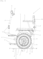
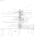
- a self-balancing vehicle 1 is of the Segway type and comprises a rolling base 2.
- the rolling base 2 comprises a chassis 3, two wheels 4 each rotatably mounted on an axis of rotation 5 and a drive device.
- the drive device comprises a motor for each wheel 4 and is configured to control the rotation of the wheels 4 and dynamically balance the self-balancing vehicle 1. Thanks to this drive device, a forward tilt of the chassis 3 leads to the self-balancing vehicle 1 moving forward and a rearward tilt of the chassis 3 leads to the self-balancing vehicle 1 moving backward or braking it.
- the self-balancing vehicle 1 is also equipped with footrests 6.
- the footrests 6 are foldable.
- the self-balancing vehicle 1 comprises adjustable armrests 7 of the type commonly encountered in the field of Segway scooters.
- the self-balancing vehicle 1 further comprises a seat 8 comprising a seat 9 and a backrest 10.
- the seat 9 and the backrest 10 are connected in an articulated manner so as to be able to fold the backrest 10 onto the seat 9.
- a handlebar 11, connected to the drive means, is provided to guide the movement to the left and to the right of the self-balancing vehicle 1 under the effect of pressure from the user to the left and to the right, respectively.
- the handlebar 11 is connected by a junction 12 to the chassis 3 and comprises articulations 13 to allow its adjustment and to allow it to be folded.
- a handlebar 11 is well known to those skilled in the art and will not be described in more detail below.
- the handlebar 11 is equipped with a control and display device 14, of the touch screen type, mounted on a support 15 to, among other things, allow the user to power up the self-balancing vehicle 1, start it or charge it. electrically.
- the self-balancing vehicle 1 is powered by an on-board rechargeable battery to which the drive means are connected.
- the self-balancing vehicle 1 comprises an anti-tilt device 16.
- an anti-tilt device 16 is configured to be able to stabilize the self-balancing vehicle 1 not only when it is stationary in a normal operating situation, but also in the event of a predetermined abnormal operating situation, for example in the event of a power failure or excessive inclination of the chassis 3, which could lead to the self-balancing vehicle 1 overturning.
- the anti-tilt device 16 is fixedly connected to the chassis 3 at a side wall 17 thereof by a first connecting piece 18 and at a bottom wall 19 of the chassis 3 by a second connecting piece 20.
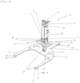
- the anti-tilt device 16 comprises a telescopic foot 21 consisting of a hollow outer tube 22 and a hollow inner tube 23 configured to slide inside the outer tube 22, so as to deploy outside the outer tube 22.
- the outer tube 22 and the inner tube 23 have a square section.
- the first connecting piece 18 and the second connecting piece 20 are connected to the external tube 22 so that the external tube 22 constitutes a fixed part of the telescopic foot 21, integral with the chassis 3, and the internal part 23 constitutes a movable part relative to the chassis 3.
- the first connecting piece 18 comprises a tab 24 screwed to the side wall 17 of the chassis 3 and a system of fixing flanges 25 tightening the external tube 22.
- the second connecting piece 20 is constituted by a plate 26 pierced with a central bore 27 in which the external tube 22 is held, and screwed onto the bottom wall 19 of the chassis 3.
- the first connecting piece 18 and the second connecting piece 19 are configured to hold the telescopic foot 21 perpendicular to the direction of movement of the self-balancing vehicle 1. It should be noted that a person skilled in the art will be able to envisage any suitable means of fixing the telescopic foot 21 to the chassis 3.
- the anti-tilt device 16 is equipped with position detection means. To do this, according to the embodiment shown in the Figures 3-12 , the anti-tilt device 16 comprises infrared (IR) sensors 28.
- the IR sensors 28 comprise a transmitter board 29 and a receiver board 30, arranged on a first side wall 31 of the outer tube 22 and on a second side wall 32 of the outer tube 22 opposite the first side wall 31.
- the transmitter board 29 comprises three transmitters 33 and the receiver board comprises three receivers 34.
- a first, second and third pair of circular through holes 36a, 36b, 36c are provided in the first side wall 31 and the second side wall 32.
- lower is meant the side facing the ground in use and by upper is meant the side in use facing away from the ground.
- Two circular holes 36a, 36b, 36c of each pair are opposite one wall 31, 32 to the other.
- the transmitter card 29 and the receiver card 30 are arranged such that the emitters 33 and receivers 34 are positioned at the through holes 36a, 36b, 36c.
- an IR signal can be transmitted and received on either side of the first 31 and second 32 side walls of the outer tube 22.
- the second pair of circular holes 36b and the third pair of circular holes 36c are located on the same horizontal plane and the first pair of circular holes 36a is located at an upper position.
- the two oblong holes 39a, 39b, 39c of each pair are of the same size and are arranged facing one side wall 37, 38 to the other.
- the major length of the first pair of oblong holes 39a is greater than the major length of the third pair of oblong holes 39c, which is itself greater than the major length of the second pair of oblong holes 39b.
- the second pair of oblong holes 39b occupies a central position between the first pair of oblong holes 39a and the third pair of oblong holes 39c.
- the oblong holes 39a, 39b, 39c are centered differently so that the center of the oblong holes 39c of the third pair occupies a central position between the center of the oblong holes 39a of the first pair and the center of the oblong holes 39b of the second pair.
- the first side wall 31 of the outer tube 22 faces the first side wall 37 of the inner tube 22 and the second side wall 32 of the outer tube 22 faces the second side wall 38 of the inner tube 23. Furthermore, the circular holes 36a, 36b, 36c and the oblong holes 39a, 39b and 39c are positioned such that in the width direction of the telescopic leg 21, the oblong holes 39a of the first pair formed in the first 37 and second 38 side walls of the inner tube 23 are adapted to face the circular holes 36a of the first pair formed in the first 31 and second 32 side walls of the outer tube 22, respectively.
- the oblong holes 39b of the second pair formed in the first 37 and the second 38 side walls of the inner tube 23 are able to be opposite the circular holes 36b of the second pair formed in the first 31 and the second 32 side walls of the outer tube 22, respectively, and the oblong holes 39c of the third pair formed in the first 37 and the second 38 side walls of the inner tube 23 are able to be opposite the circular holes 36c of the third pair formed in the first 31 and the second 32 side walls of the outer tube 22, respectively.
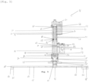
- the linear actuation device 41 comprises motor means, here an electric motor 42, and a guide bar, here a trapezoidal screw 43, configured to be rotated by the motor means.
- the screw 43 passes through an upper wall 44 of the outer tube 22 and extends inside the telescopic foot 21 over the entire length of the outer tube 22 and partially in the inner tube. 23, its free end 45 being located inside the inner tube 23.
- the linear actuation device 41 is configured to move the inner tube 23 relative to the outer tube 22.
- the anti-tilt device 16 also comprises a compression spring 46.
- the compression spring 46 bears against the lower face 47 of the upper wall 44 of the outer tube 22 and against the upper face 48 of an upper wall 49 of the inner tube 23, by means of supports 50.
- the compression spring 46 is configured to be stressed in compression by the movement of the inner tube 23 towards the inside of the outer tube 22 and thus is configured to exert pressure on the upper wall 40 of the inner tube 23 so as to deploy the inner tube 23 out of the outer tube 22.
- a nut 51 which constitutes the stop piece, is mounted screwed onto the screw 43, inside the internal tube 23.
- the nut 51 is of square section and is sized such that the external surface 52 of the nut 51 matches the internal surface 53 of the internal tube 23. Consequently, under the effect of the rotation of the screw 43, the nut 51 is movable along the screw 43 between the free end 45 of the screw 43 and the lower face 54 of the upper wall 49 of the internal tube 23.
- the nut 51 is thus configured to raise the internal tube 23 by exerting pressure on the upper wall 49 of the internal tube 23.
- the upper wall 40 of the inner tube 23 constitutes a biasing portion of the inner tube 23 for extending/retracting the inner tube 23 relative to the outer tube 22, i.e., in the assembled state of the self-balancing vehicle 1, lowering/raising the inner tube 23, by means of the compression spring 46 and the nut 51, respectively.
- the anti-tilt device 16 further comprises locking means 55 for locking the inner tube 23 in position.
- the locking means 55 comprise a lifting magnet 56 and a hook 57 configured to be actuated by the lifting magnet 56 by means of a piston 58.
- a through hole 59 is provided in the first side wall 31 of the outer tube 22 and, correspondingly, a through hole 60 is provided in the first side wall 37 of the inner tube 23.
- the inner tube 23 is held in position when the through hole 59 of the outer tube 22 and the through hole 60 of the inner tube 23 coincide, the free end 61 of the hook 57 bearing against the upper surface 62 of the through hole 60 of the inner tube 23 so as to prevent the deployment of the inner tube 23 relative to the outer tube 22 in the lowered position.
- the lifting magnet 56 is configured to actuate the hook 48 in the event of a power failure, either following a specific command from the control means or following a power failure.
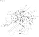
- the fork 64 is constituted by a flat plate 65 contained in a plane perpendicular to the inner tube 23.
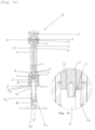
- the fork 64 shown in the Figures 3-4 has three branches 66. Skids 67 are arranged below the ends 68 of the branches 66 and are configured to come into contact with the ground, and thus each form a contact region.
- the fork 64 constitutes a contact portion of the anti-tilt device 16, intended to come into contact with the ground so as to immobilize the self-balancing vehicle 1.
- the fork 64 is thus movable thanks to the movements of the internal tube 23 between a raised position where it does not oppose the movement of the self-balancing vehicle 1 and a lowered position where it comes into contact with the ground.
- the fork 64 is in the lowered position, the forward or backward tilting of the self-balancing vehicle 1 is prevented by an arching effect occurring between the inner tube 23 and the outer tube 22, an effect which itself prevents the inner tube 23 from rising into the outer tube 22.
- the fork 64 and the tubes 22 and 23 will be specifically sized for this arching effect, in particular by ensuring that there is a fork length allowing this effect taking into account the remaining nesting length between the outer tubes 22 and 23 when the fork 64 is in the lowered position and the self-balancing vehicle 1 has attempted to tilt.
- the inner tube 23 is connected to the flat plate 65 in a rearwardly offset position, as shown in the Figures 4-8 .
- This has the effect of further blocking a forward tilt of the self-balancing vehicle 1.
- front is meant the side towards which the self-balancing vehicle 1 is moving forward and by rear is meant the side towards which the self-balancing vehicle 1 is moving backward.
- the self-balancing vehicle 1 comprises a stabilizing cylinder 69.
- the stabilizing cylinder 69 is fixed to the chassis 3 and is configured to press the fork 64 to the ground.
- a piston 70 is deployed at the user's command once the fork 64 is in contact with the ground.
- Such a stabilizing cylinder 69 has the function of reinforcing the stability of the self-balancing vehicle 1 immobilized by the anti-tilt device 16.
- the piston 70 is configured to come into contact with the rear part of the fork 64.
- Control means are provided for controlling the linear actuator 41, the locking means 46 and the stabilizing cylinder 69.
- the control means are also connected to the IR sensors 28 and to the battery.
- control means may, for example, comprise a computer, such as constituted by a microprocessor, configured to control the various components of the self-balancing vehicle 1 based on information from various sensors (gyroscopic system, accelerometer, potentiometer, etc.).
- the anti-tipper 16 is shown in the raised state.
- the inner tube 23 is in the raised position and the fork 64 is in the locked position, that is, the inner tube 23 is retracted inside the outer tube 22.
- the fork 64 is not in contact with the ground and is raised enough not to oppose the movement of the self-balancing vehicle 1.
- the compression spring 46 is compressed.
- the nut 51 is at the free end 45 of the screw 44.
- the hook 57 is engaged against the hole 60 of the inner tube 23.
- This locked position of the fork 64 is detected by the IR sensors 28.
- the circular holes 36a of the first pair and the oblong holes 39a of the first pair coincide.
- the emitted IR signal is not received. Since the circular holes 36b of the second pair and the oblong holes 39b of the second pair do not coincide, the emitted IR signal is not received. The circular holes 36c of the third pair and the oblong holes 39c of the third coinciding pair, the emitted IR signal is received. This information relating to the IR signals is transmitted to the control means which are able to stop the rotation of the screw 43 when it is reached.
- a command from the user causes the control means to initially rotate the screw 43 in a first direction. Because the external surface 52 of the nut 51 matches the internal surface 53 of the internal tube 23, the nut 51 is caused to rise along the screw 43 until it comes into abutment against the lower face 54 of the upper wall 49 of the internal tube 23. There, the control means control the lifting magnet 56, by simply cutting off the power supply to the latter, so as to raise the hook 57, the descent of the internal tube 23 under the effect of the relaxation of the compression spring 46 then being prevented by the presence of the nut 51 in abutment against the lower face 54 of the upper wall 49 of the internal tube 23.
- the control means control the linear actuating device 41 so as to rotate the screw 43 in the other direction, which has the effect of sliding the internal tube 23 out of the external tube 22, under the effect of the compression spring 46. acting on the upper wall 49 of the inner tube 23, up to a lowered position of the fork 64, in contact with the ground by its pads 67, preventing the tilting of the self-balancing vehicle 1, as shown in the Figures 2 , 4 , 6 And 10 .
- the lowered position varies depending on the nature of the ground. For example, if the ground has a recess between the wheels 4, the fork 64 will be below the line connecting the contact regions of the wheels 4 with the ground. If the ground is raised between the wheels 4, the fork 64 will be above the line connecting the contact regions of the wheels 4 with the ground.
- Such operation corresponds to a so-called normal use where the commands come from the user who wishes to stabilize the self-balancing vehicle 1 when stationary, for example to get off or save the battery. This is the first type of command.
- the locking means 46 unlock, either automatically in the event of a power failure or automatically on command of the control means when a detected state corresponds to a predetermined state, for example an excessively pronounced inclination of the chassis 3.
- a predetermined state for example an excessively pronounced inclination of the chassis 3.
- the control means may comprise a memory which contains predetermined states of abnormal operation of the self-balancing vehicle 1. In this case, the hook 57 is raised by the lifting magnet 56, the power supply to the latter no longer being ensured.
- the relaxation of the compression spring 46 leads to lowering the inner tube 23 until the fork 64 comes into contact with the ground by its pads 67, contact leading to the blocking of the inner tube 23 in the outer tube 22 by bracing and preventing a rise of the fork 64, which prevents the unwanted tilting of the self-balancing vehicle 1. Thanks to the compression spring 46, such a deployment can thus be immediate to secure the self-balancing vehicle 1.
- This lowered position such as represented on the Figures 2 , 4 , 6 And 10 , is detected by the IR sensors 28.
- the circular holes 36a of the first pair and the oblong holes 39a of the first pair coincide.
- the nut 51 being interposed at this level, the emitted IR signal is not received.
- the circular holes 36b of the second pair and the oblong holes 39b of the second pair do not coincide, the emitted IR signal is not received.
- the circular holes 36c of the third pair and the oblong holes 39c of the third pair do not coincide, the emitted IR signal is not received. This information relating to the IR signals is transmitted to the control means.
- a command from the user causes the control means to rotate the screw 43 in the first direction of rotation.
- the nut 51 rises along the screw 34 until it is brought into abutment against the lower face 54 of the upper wall 49 of the inner tube 23, which has the effect of raising the inner tube 23 to a raised position of the fork 64, the compression spring 46 being brought into a compressed state.
- This raised position as shown in the Figures 1 , 7 And 11 , is detected by the IR sensors 28.
- the circular holes 36a of the first pair and the oblong holes 39a of the first pair coincide.
- the emitted IR signal is received.
- the circular holes 36b of the second pair and the oblong holes 39b of the second pair coincide with no obstacle interposed, the emitted IR signal is received.
- the circular holes 36c of the third pair and the oblong holes 39c of the third pair coincide without any interposed obstacle, the emitted IR signal is received.
- This information relating to the IR signals is transmitted to the control means which are capable of stopping the rotation of the screw 43 when the raised position is reached.
- the hook 57 is lowered so that its free end 61 is in the coinciding holes 59 and 60, as can be seen in the Figures 8 And 12 .
- the control means control the rotation of the screw 43 in the second direction of rotation to lower the inner tube 23 as previously, which brings the free end 61 of the hook 57 into abutment against the upper surface 62 of the hole 60 of the inner tube 23.
- the fork 64 is thus brought into a locked position, intermediate between the raised position and the lowered position. In this locked position, the fork 54 does not oppose the movement of the self-balancing vehicle 1. This position is detected by the IR sensors 28.
- the circular holes 36a of the first pair and the oblong holes 39a of the first pair coincide. No obstacle being interposed, the emitted IR signal is received.
- the circular holes 36b of the second pair and the oblong holes 39b of the second pair not coinciding, the emitted IR signal is not received.
- the circular holes 36c of the third pair and the oblong holes 39c of the third pair coinciding, the emitted IR signal is received. This information relating to the IR signals is transmitted to the control means which are able to stop the rotation of the screw 43 when the locked position is reached.
- the device is rearmed, to allow, if necessary, operation according to the second type of control, by bringing the nut 42 to the level of the free end 45 of the screw 43 while continuing the rotation of the screw 43.
Landscapes
- Engineering & Computer Science (AREA)
- Mechanical Engineering (AREA)
- Chemical & Material Sciences (AREA)
- Combustion & Propulsion (AREA)
- Transportation (AREA)
- Health & Medical Sciences (AREA)
- Life Sciences & Earth Sciences (AREA)
- Animal Behavior & Ethology (AREA)
- General Health & Medical Sciences (AREA)
- Public Health (AREA)
- Veterinary Medicine (AREA)
- Motorcycle And Bicycle Frame (AREA)
- Vehicle Body Suspensions (AREA)
Claims (10)
- - Selbstausbalancierendes Fahrzeug (1), umfassend:- eine Rollbasis (2), die Rollbasis (2) umfassend ein Fahrgestell (3), zwei Räder (4), die jeweils geeignet sind, um um eine Drehachse (5) zu drehen und eine Antriebsvorrichtung, die konfiguriert ist, um die Drehung der Räder (4) zu steuern und das Fahrzeug (1) dynamisch zu ausbalancieren; und- eine Antikippvorrichtung (61),dadurch gekennzeichnet, dass die Antikippvorrichtung (61) Folgendes umfasst:- einen Teleskopfuß (21), umfassend einen feststehenden (22) und einen beweglichen (23) Abschnitt;- ein Kontaktstück (64), das mit dem beweglichen Abschnitt (23) verbunden und konfiguriert ist, um mit dem Boden in Kontakt zu kommen, wobei der bewegliche Abschnitt (23) entlang einer Längsachse des feststehenden Abschnitts (22) verschiebbar ist, zwischen einer angehobenen Position, in der das Kontaktstück (64) einer Verlagerung des Fahrzeugs (1) nicht entgegensteht, und einer abgesenkten Position, in der das Kontaktstück (64) mit dem Boden in Kontakt kommt, um ein Kippen der Rollbasis (2) zu verhindern, wobei das Kontaktstück (64) mindestens einen Kontaktbereich mit dem Boden aufweist, der von der Längsachse des feststehenden Abschnitts (22) versetzt ist, sodass die Kraft, die aus dem Kontakt mit dem Boden resultiert, ein solches Moment auf den beweglichen Abschnitt (23) ausübt, dass dieser in dem feststehenden Abschnitt (22) durch Momentensperre blockiert wird;- eine lineare Betätigungsvorrichtung (41), umfassend Antriebseinrichtungen (42) und eine Führungsstange (43), die ein freies Ende (45) aufweist, das sich im Inneren des beweglichen Abschnitts (23) befindet,- Verriegelungseinrichtungen (55) des beweglichen Abschnitts (23), die konfiguriert sind, um den beweglichen Abschnitt (23) in einer Verriegelungsposition zu verriegeln, wobei die Verriegelungsposition eine Zwischenposition zwischen der angehobenen Position und der abgesenkten Position ist und die Verriegelungseinrichtungen geeignet sind, um den beweglichen Abschnitt (23) automatisch zu entriegeln;- eine Druckfeder (46), die an einem Belastungsabschnitt (49) des beweglichen Abschnitts (23) anliegt, der konfiguriert ist, um durch die Verlagerung des Kontaktabschnitts (64) zwischen der abgesenkten Position und der angehobenen Position druckbelastet zu werden, wobei der Kontaktabschnitt (64) konfiguriert ist, um unter der Wirkung der Druckfeder (46) aus der Verriegelungsposition in die abgesenkte Position verlagert zu werden;- ein Arretierstück (51), das im Inneren des beweglichen Abschnitts (23) angeordnet und konfiguriert ist, um unter der Wirkung der Antriebseinrichtungen (42) der linearen Antriebsvorrichtung (41) entlang der Führungsstange (43) zwischen dem freien Ende (45) der Führungsstange (43) und einer Anschlagsposition in Anlage gegen den Belastungsabschnitt (49) des beweglichen Abschnitts (23) verlagerbar zu sein; und- Steuerungseinrichtungen der linearen Betätigungsvorrichtung (41) und Verriegelungseinrichtungen (55), die konfiguriert sind, um gleichzeitig die lineare Betätigungsvorrichtung (41) und die Verriegelungseinrichtungen (55) auf einen ersten, von dem Benutzer stammenden Befehlstyp hin zu betätigen und automatisch die Verriegelungseinrichtungen (55) auf einen zweiten Befehlstyp hin infolge des Auftretens eines vorher festgelegten Zustands zu betätigen.
- - Selbstausbalancierendes Fahrzeug (1) nach Anspruch 1, dadurch gekennzeichnet, dass die Führungsstange (43) eine Endlosschnecke ist (43) und das Arretierstück (51) eine Mutter (51) ist, die im Inneren des beweglichen Abschnitts (23) angeordnet und in Bezug auf diesen gegen Drehung gesichert ist, wobei die Mutter (51) auf die Schnecke (43) geschraubt ist und die Antriebseinrichtungen (42) konfiguriert, um die Schnecke (43) in die zwei Drehrichtungen zu drehen, sodass die Verschiebung der Mutter (51) durch die Drehung der Schnecke (43) unter der Wirkung der Antriebseinrichtungen (42) erlangt wird.
- - Selbstausbalancierendes Fahrzeug (1) nach einem der Ansprüche 1 und 2, dadurch gekennzeichnet, dass der feststehende Abschnitt (22), der bewegliche Abschnitt (23) und das Arretierstück (51) von einem quadratischen Querschnitt sind.
- - Selbstausbalancierendes Fahrzeug (1) nach einem der Ansprüche 1 bis 3, dadurch gekennzeichnet, dass die Verriegelungseinrichtungen (55) einen Hubmagneten (56) und einen Haken (57), der durch den Hubmagneten (56) betätigbar ist, wobei ein Loch (59) in dem feststehenden Abschnitt (22) ausgebildet ist, und ein Loch (60) in dem beweglichen Abschnitt (23) ausgebildet ist, sodass der Haken (57) konfiguriert ist, um den beweglichen Abschnitt (23) auf Höhe des Lochs davon zu blockieren, umfassen.
- - Selbstausbalancierendes Fahrzeug (1) nach einem der Ansprüche 1 bis 4, dadurch gekennzeichnet, dass der Kontaktabschnitt (64) einen ebenen Abschnitt (65) umfasst, umfassend drei Kontaktbereiche (68, 67).
- - Selbstausbalancierendes Fahrzeug (1) nach einem der Ansprüche 1 bis 5, dadurch gekennzeichnet, dass es mindestens einen IR-Sensor (28) umfasst, der konfiguriert ist, um die Position des Kontaktstücks (64) zu erfassen, wobei mindestens ein Paar kreisförmiger Durchgangslöcher (36a, 36b, 36c) und mindestens ein Paar entsprechender Langlöcher (39a, 39b, 39c) in dem feststehenden Abschnitt (22) bzw. dem beweglichen Abschnitt (23) ausgebildet sind.
- - Selbstausbalancierendes Fahrzeug (1) nach einem der Ansprüche 1 bis 6, dadurch auszeichnet, dass die Verriegelungseinrichtungen (55) vom Typ für Stromausfall sind und konfiguriert sind, um den beweglichen Abschnitt (23) im Fall eines Stromausfalls automatisch zu entriegeln.
- - Selbstausbalancierendes Fahrzeug (1) nach einem der Ansprüche 1 bis 7, dadurch auszeichnet, dass es ferner einen Stabilisierungszylinder (69) umfasst, das konfiguriert ist, um von den Steuerungseinrichtungen auf einen ersten Befehlstyp hin betätigt zu werden, und das konfiguriert ist, um in abgesenkter Position an dem Kontaktstück (64) anzuliegen.
- - Selbstausbalancierendes Fahrzeug (1) nach einem der Ansprüche 1 bis 8, dadurch gekennzeichnet, dass es einen Lenker (11) umfasst, wobei der Lenker (11) mit den Antriebseinrichtungen verbunden ist und konfiguriert ist, um die Verlagerung des Fahrzeugs (1) nach links und nach rechts unter der Wirkung eines Drucks des Benutzer nach links bzw. nach rechts zu steuern.
- - Selbstausbalancierendes Fahrzeug (1) nach einem der Ansprüche 1 bis 9, dadurch auszeichnet, dass es eine Batterie umfasst, die konfiguriert ist, um mindestens die Antriebseinrichtungen, die Steuerungseinrichtungen, die lineare Betätigungsvorrichtung (41) und die Verriegelungseinrichtungen (55) zu versorgen.
Applications Claiming Priority (1)
| Application Number | Priority Date | Filing Date | Title |
|---|---|---|---|
| FR2108692A FR3126118B1 (fr) | 2021-08-13 | 2021-08-13 | Véhicule à auto-équilibrage avec dispositif anti-bascule |
Publications (3)
| Publication Number | Publication Date |
|---|---|
| EP4134295A1 EP4134295A1 (de) | 2023-02-15 |
| EP4134295B1 true EP4134295B1 (de) | 2024-11-13 |
| EP4134295C0 EP4134295C0 (de) | 2024-11-13 |
Family
ID=77711241
Family Applications (1)
| Application Number | Title | Priority Date | Filing Date |
|---|---|---|---|
| EP22189604.6A Active EP4134295B1 (de) | 2021-08-13 | 2022-08-09 | Selbstausbalancierendes fahrzeug mit anti-kippvorrichtung |
Country Status (2)
| Country | Link |
|---|---|
| EP (1) | EP4134295B1 (de) |
| FR (1) | FR3126118B1 (de) |
Family Cites Families (3)
| Publication number | Priority date | Publication date | Assignee | Title |
|---|---|---|---|---|
| IT1401372B1 (it) * | 2010-08-05 | 2013-07-18 | Carrozzeria 71 S R L | Gruppo di trasformazione applicabile a mezzi di locomozione "segway"(r) |
| DE102014113278B4 (de) * | 2014-09-15 | 2016-08-25 | Freee Mobility Gmbh | Stützsystem, elektronisch selbstbalancierter Rollstuhl, Verfahren zum Steuern eines Stützsystems und Umrüstsatz |
| WO2020058582A1 (fr) | 2018-09-17 | 2020-03-26 | PRÉVOT, Corinne | Véhicule automobile de type gyropode |
-
2021
- 2021-08-13 FR FR2108692A patent/FR3126118B1/fr active Active
-
2022
- 2022-08-09 EP EP22189604.6A patent/EP4134295B1/de active Active
Also Published As
| Publication number | Publication date |
|---|---|
| EP4134295A1 (de) | 2023-02-15 |
| FR3126118A1 (fr) | 2023-02-17 |
| EP4134295C0 (de) | 2024-11-13 |
| FR3126118B1 (fr) | 2023-09-01 |
Similar Documents
| Publication | Publication Date | Title |
|---|---|---|
| EP1349528B1 (de) | Motorisierter operationstisch mit mehreren sektionen | |
| EP2825428B2 (de) | Fahrzeugpierradblockanordnung und -installation | |
| EP3908547B1 (de) | Hubarbeitsbühne mit abnehmbarer steuerkonsole, mit einer schutzvorrichtung zur verhinderung von quetschungen der bedienperson | |
| FR2857400A1 (fr) | Verrou destine a relier deux panneaux d'une structure d'aeroplane | |
| WO2011121211A1 (fr) | Tricycle | |
| EP3962844B1 (de) | Vorrichtung zum blockieren eines fahrzeugs vor einer ladebrücke | |
| EP2851320B1 (de) | Keilvorrichtung als Wegfahrsperre für Fahrzeug | |
| EP4134295B1 (de) | Selbstausbalancierendes fahrzeug mit anti-kippvorrichtung | |
| EP3931064B1 (de) | System zur immobilisierung eines medizinischen roboters | |
| FR3049574B1 (fr) | Palonnier d’aeronef pourvu d’un systeme de reglage motorise de la position de pedales. | |
| EP0276186B1 (de) | Vorrichtung zur Trägheitsverriegelung für Fahrzeugsitze | |
| EP4031477B1 (de) | Korb-, insbesondere luftkorbhubvorrichtung | |
| FR2521500A1 (fr) | Vehicule automobile destine a etre utilise par une personne handicapee physiquement, sans que celle-ci quitte son fauteuil roulant, et sans aucune aide exterieure | |
| FR3050929B1 (fr) | Vehicule adapte a transporter un utilisateur a mobilite reduite | |
| EP0377222B1 (de) | Ausziehleiter auf einem Fahrgestell | |
| FR3100521A1 (fr) | Procédé de contrôle d’un volant de véhicule | |
| WO2004089732A2 (fr) | Dispositif et procede de stabilisation pour vehicule a deux roues, vehicule ainsi equipe | |
| FR3034723A1 (fr) | Dispositif de verrouillage de banquette arriere | |
| EP1808384B1 (de) | Trittbrett sowie damit ausgestattetes Fahrzeug | |
| FR3162002A1 (fr) | Dispositif de motorisation pour fauteuil roulant | |
| FR2714899A1 (fr) | Dispositif de levage mobile, notamment destiné au levage de véhicules. | |
| WO2020254938A1 (fr) | Véhicule à moteur pour personne à mobilité réduite, avec montée/descente facilitée | |
| WO2022218763A1 (fr) | Escalier hélicoïdal à mât central pivotant | |
| FR2875799A1 (fr) | Dispositif de levage d'une charge en particulier d'un vehicule automobile | |
| FR3007012A1 (fr) | Plateforme elevatrice de personnel integrant un reposoir pour immobiliser le panier de la plateforme |
Legal Events
| Date | Code | Title | Description |
|---|---|---|---|
| PUAI | Public reference made under article 153(3) epc to a published international application that has entered the european phase |
Free format text: ORIGINAL CODE: 0009012 |
|
| STAA | Information on the status of an ep patent application or granted ep patent |
Free format text: STATUS: THE APPLICATION HAS BEEN PUBLISHED |
|
| AK | Designated contracting states |
Kind code of ref document: A1 Designated state(s): AL AT BE BG CH CY CZ DE DK EE ES FI FR GB GR HR HU IE IS IT LI LT LU LV MC MK MT NL NO PL PT RO RS SE SI SK SM TR |
|
| STAA | Information on the status of an ep patent application or granted ep patent |
Free format text: STATUS: REQUEST FOR EXAMINATION WAS MADE |
|
| 17P | Request for examination filed |
Effective date: 20230814 |
|
| RBV | Designated contracting states (corrected) |
Designated state(s): AL AT BE BG CH CY CZ DE DK EE ES FI FR GB GR HR HU IE IS IT LI LT LU LV MC MK MT NL NO PL PT RO RS SE SI SK SM TR |
|
| GRAP | Despatch of communication of intention to grant a patent |
Free format text: ORIGINAL CODE: EPIDOSNIGR1 |
|
| STAA | Information on the status of an ep patent application or granted ep patent |
Free format text: STATUS: GRANT OF PATENT IS INTENDED |
|
| RIC1 | Information provided on ipc code assigned before grant |
Ipc: A61G 5/10 20060101ALI20230914BHEP Ipc: B62K 11/00 20060101ALI20230914BHEP Ipc: B62H 1/06 20060101ALI20230914BHEP Ipc: B62D 37/04 20060101AFI20230914BHEP |
|
| INTG | Intention to grant announced |
Effective date: 20231002 |
|
| 19U | Interruption of proceedings before grant |
Effective date: 20221207 |
|
| 19W | Proceedings resumed before grant after interruption of proceedings |
Effective date: 20241001 |
|
| GRAS | Grant fee paid |
Free format text: ORIGINAL CODE: EPIDOSNIGR3 |
|
| GRAA | (expected) grant |
Free format text: ORIGINAL CODE: 0009210 |
|
| STAA | Information on the status of an ep patent application or granted ep patent |
Free format text: STATUS: THE PATENT HAS BEEN GRANTED |
|
| RAP3 | Party data changed (applicant data changed or rights of an application transferred) |
Owner name: GUSNGO |
|
| AK | Designated contracting states |
Kind code of ref document: B1 Designated state(s): AL AT BE BG CH CY CZ DE DK EE ES FI FR GB GR HR HU IE IS IT LI LT LU LV MC MK MT NL NO PL PT RO RS SE SI SK SM TR |
|
| REG | Reference to a national code |
Ref country code: GB Ref legal event code: FG4D Free format text: NOT ENGLISH |
|
| REG | Reference to a national code |
Ref country code: CH Ref legal event code: EP |
|
| REG | Reference to a national code |
Ref country code: DE Ref legal event code: R096 Ref document number: 602022007657 Country of ref document: DE |
|
| REG | Reference to a national code |
Ref country code: IE Ref legal event code: FG4D Free format text: LANGUAGE OF EP DOCUMENT: FRENCH |
|
| U01 | Request for unitary effect filed |
Effective date: 20241211 |
|
| U07 | Unitary effect registered |
Designated state(s): AT BE BG DE DK EE FI FR IT LT LU LV MT NL PT RO SE SI Effective date: 20250121 |
|
| PG25 | Lapsed in a contracting state [announced via postgrant information from national office to epo] |
Ref country code: HR Free format text: LAPSE BECAUSE OF FAILURE TO SUBMIT A TRANSLATION OF THE DESCRIPTION OR TO PAY THE FEE WITHIN THE PRESCRIBED TIME-LIMIT Effective date: 20241113 Ref country code: IS Free format text: LAPSE BECAUSE OF FAILURE TO SUBMIT A TRANSLATION OF THE DESCRIPTION OR TO PAY THE FEE WITHIN THE PRESCRIBED TIME-LIMIT Effective date: 20250313 |
|
| PG25 | Lapsed in a contracting state [announced via postgrant information from national office to epo] |
Ref country code: ES Free format text: LAPSE BECAUSE OF FAILURE TO SUBMIT A TRANSLATION OF THE DESCRIPTION OR TO PAY THE FEE WITHIN THE PRESCRIBED TIME-LIMIT Effective date: 20241113 |
|
| PG25 | Lapsed in a contracting state [announced via postgrant information from national office to epo] |
Ref country code: NO Free format text: LAPSE BECAUSE OF FAILURE TO SUBMIT A TRANSLATION OF THE DESCRIPTION OR TO PAY THE FEE WITHIN THE PRESCRIBED TIME-LIMIT Effective date: 20250213 |
|
| PG25 | Lapsed in a contracting state [announced via postgrant information from national office to epo] |
Ref country code: GR Free format text: LAPSE BECAUSE OF FAILURE TO SUBMIT A TRANSLATION OF THE DESCRIPTION OR TO PAY THE FEE WITHIN THE PRESCRIBED TIME-LIMIT Effective date: 20250214 |
|
| PG25 | Lapsed in a contracting state [announced via postgrant information from national office to epo] |
Ref country code: PL Free format text: LAPSE BECAUSE OF FAILURE TO SUBMIT A TRANSLATION OF THE DESCRIPTION OR TO PAY THE FEE WITHIN THE PRESCRIBED TIME-LIMIT Effective date: 20241113 |
|
| PG25 | Lapsed in a contracting state [announced via postgrant information from national office to epo] |
Ref country code: RS Free format text: LAPSE BECAUSE OF FAILURE TO SUBMIT A TRANSLATION OF THE DESCRIPTION OR TO PAY THE FEE WITHIN THE PRESCRIBED TIME-LIMIT Effective date: 20250213 |
|
| PG25 | Lapsed in a contracting state [announced via postgrant information from national office to epo] |
Ref country code: SM Free format text: LAPSE BECAUSE OF FAILURE TO SUBMIT A TRANSLATION OF THE DESCRIPTION OR TO PAY THE FEE WITHIN THE PRESCRIBED TIME-LIMIT Effective date: 20241113 |
|
| PG25 | Lapsed in a contracting state [announced via postgrant information from national office to epo] |
Ref country code: SK Free format text: LAPSE BECAUSE OF FAILURE TO SUBMIT A TRANSLATION OF THE DESCRIPTION OR TO PAY THE FEE WITHIN THE PRESCRIBED TIME-LIMIT Effective date: 20241113 |
|
| PG25 | Lapsed in a contracting state [announced via postgrant information from national office to epo] |
Ref country code: CZ Free format text: LAPSE BECAUSE OF FAILURE TO SUBMIT A TRANSLATION OF THE DESCRIPTION OR TO PAY THE FEE WITHIN THE PRESCRIBED TIME-LIMIT Effective date: 20241113 |
|
| PLBE | No opposition filed within time limit |
Free format text: ORIGINAL CODE: 0009261 |
|
| STAA | Information on the status of an ep patent application or granted ep patent |
Free format text: STATUS: NO OPPOSITION FILED WITHIN TIME LIMIT |
|
| U20 | Renewal fee for the european patent with unitary effect paid |
Year of fee payment: 4 Effective date: 20250828 |
|
| 26N | No opposition filed |
Effective date: 20250814 |