EP4134189A1 - Three-dimensional powder bed fusion additive manufacturing apparatus - Google Patents
Three-dimensional powder bed fusion additive manufacturing apparatus Download PDFInfo
- Publication number
- EP4134189A1 EP4134189A1 EP22189581.6A EP22189581A EP4134189A1 EP 4134189 A1 EP4134189 A1 EP 4134189A1 EP 22189581 A EP22189581 A EP 22189581A EP 4134189 A1 EP4134189 A1 EP 4134189A1
- Authority
- EP
- European Patent Office
- Prior art keywords
- unit
- plate
- flow path
- shaped
- path forming
- Prior art date
- Legal status (The legal status is an assumption and is not a legal conclusion. Google has not performed a legal analysis and makes no representation as to the accuracy of the status listed.)
- Pending
Links
Images







Classifications
-
- B—PERFORMING OPERATIONS; TRANSPORTING
- B22—CASTING; POWDER METALLURGY
- B22F—WORKING METALLIC POWDER; MANUFACTURE OF ARTICLES FROM METALLIC POWDER; MAKING METALLIC POWDER; APPARATUS OR DEVICES SPECIALLY ADAPTED FOR METALLIC POWDER
- B22F12/00—Apparatus or devices specially adapted for additive manufacturing; Auxiliary means for additive manufacturing; Combinations of additive manufacturing apparatus or devices with other processing apparatus or devices
- B22F12/70—Gas flow means
-
- B—PERFORMING OPERATIONS; TRANSPORTING
- B01—PHYSICAL OR CHEMICAL PROCESSES OR APPARATUS IN GENERAL
- B01D—SEPARATION
- B01D46/00—Filters or filtering processes specially modified for separating dispersed particles from gases or vapours
- B01D46/10—Particle separators, e.g. dust precipitators, using filter plates, sheets or pads having plane surfaces
-
- B—PERFORMING OPERATIONS; TRANSPORTING
- B01—PHYSICAL OR CHEMICAL PROCESSES OR APPARATUS IN GENERAL
- B01D—SEPARATION
- B01D46/00—Filters or filtering processes specially modified for separating dispersed particles from gases or vapours
- B01D46/10—Particle separators, e.g. dust precipitators, using filter plates, sheets or pads having plane surfaces
- B01D46/12—Particle separators, e.g. dust precipitators, using filter plates, sheets or pads having plane surfaces in multiple arrangements
- B01D46/121—V-type arrangements
-
- B—PERFORMING OPERATIONS; TRANSPORTING
- B22—CASTING; POWDER METALLURGY
- B22F—WORKING METALLIC POWDER; MANUFACTURE OF ARTICLES FROM METALLIC POWDER; MAKING METALLIC POWDER; APPARATUS OR DEVICES SPECIALLY ADAPTED FOR METALLIC POWDER
- B22F10/00—Additive manufacturing of workpieces or articles from metallic powder
- B22F10/20—Direct sintering or melting
- B22F10/28—Powder bed fusion, e.g. selective laser melting [SLM] or electron beam melting [EBM]
-
- B—PERFORMING OPERATIONS; TRANSPORTING
- B22—CASTING; POWDER METALLURGY
- B22F—WORKING METALLIC POWDER; MANUFACTURE OF ARTICLES FROM METALLIC POWDER; MAKING METALLIC POWDER; APPARATUS OR DEVICES SPECIALLY ADAPTED FOR METALLIC POWDER
- B22F10/00—Additive manufacturing of workpieces or articles from metallic powder
- B22F10/70—Recycling
- B22F10/77—Recycling of gas
-
- B—PERFORMING OPERATIONS; TRANSPORTING
- B33—ADDITIVE MANUFACTURING TECHNOLOGY
- B33Y—ADDITIVE MANUFACTURING, i.e. MANUFACTURING OF THREE-DIMENSIONAL [3D] OBJECTS BY ADDITIVE DEPOSITION, ADDITIVE AGGLOMERATION OR ADDITIVE LAYERING, e.g. BY 3D PRINTING, STEREOLITHOGRAPHY OR SELECTIVE LASER SINTERING
- B33Y30/00—Apparatus for additive manufacturing; Details thereof or accessories therefor
-
- B—PERFORMING OPERATIONS; TRANSPORTING
- B33—ADDITIVE MANUFACTURING TECHNOLOGY
- B33Y—ADDITIVE MANUFACTURING, i.e. MANUFACTURING OF THREE-DIMENSIONAL [3D] OBJECTS BY ADDITIVE DEPOSITION, ADDITIVE AGGLOMERATION OR ADDITIVE LAYERING, e.g. BY 3D PRINTING, STEREOLITHOGRAPHY OR SELECTIVE LASER SINTERING
- B33Y40/00—Auxiliary operations or equipment, e.g. for material handling
-
- B—PERFORMING OPERATIONS; TRANSPORTING
- B01—PHYSICAL OR CHEMICAL PROCESSES OR APPARATUS IN GENERAL
- B01D—SEPARATION
- B01D45/00—Separating dispersed particles from gases or vapours by gravity, inertia, or centrifugal forces
- B01D45/04—Separating dispersed particles from gases or vapours by gravity, inertia, or centrifugal forces by utilising inertia
- B01D45/08—Separating dispersed particles from gases or vapours by gravity, inertia, or centrifugal forces by utilising inertia by impingement against baffle separators
-
- B—PERFORMING OPERATIONS; TRANSPORTING
- B22—CASTING; POWDER METALLURGY
- B22F—WORKING METALLIC POWDER; MANUFACTURE OF ARTICLES FROM METALLIC POWDER; MAKING METALLIC POWDER; APPARATUS OR DEVICES SPECIALLY ADAPTED FOR METALLIC POWDER
- B22F2999/00—Aspects linked to processes or compositions used in powder metallurgy
-
- Y—GENERAL TAGGING OF NEW TECHNOLOGICAL DEVELOPMENTS; GENERAL TAGGING OF CROSS-SECTIONAL TECHNOLOGIES SPANNING OVER SEVERAL SECTIONS OF THE IPC; TECHNICAL SUBJECTS COVERED BY FORMER USPC CROSS-REFERENCE ART COLLECTIONS [XRACs] AND DIGESTS
- Y02—TECHNOLOGIES OR APPLICATIONS FOR MITIGATION OR ADAPTATION AGAINST CLIMATE CHANGE
- Y02P—CLIMATE CHANGE MITIGATION TECHNOLOGIES IN THE PRODUCTION OR PROCESSING OF GOODS
- Y02P10/00—Technologies related to metal processing
- Y02P10/25—Process efficiency
Definitions
- the present invention relates to a three-dimensional powder bed fusion additive manufacturing (PBF-AM) apparatus.
- PPF-AM three-dimensional powder bed fusion additive manufacturing
- PPF-AM three-dimensional powder bed fusion additive manufacturing
- Patent Literature 1 JP 2019-7051 A
- an inside of a vacuum chamber is maintained in a vacuum state by a vacuum pump to build the manufactured object. Therefore, when a smoke phenomenon occurs during building, the powder scattered by smoke may enter the vacuum pump and adversely affect the vacuum pump.
- the present invention has been made to solve the above problems, and an object thereof is to provide a three-dimensional PBF-AM apparatus capable of suppressing the intrusion of powder into the vacuum pump without reducing the exhaust efficiency as much as possible.
- the three-dimensional PBF-AM apparatus includes a stage on which the powder is spread, the vacuum chamber in which the stage is disposed, the vacuum pump that evacuates the gas in the vacuum chamber, and a powder capturing device disposed on the intake side of the vacuum pump.
- the powder capturing device includes a plurality of flow path forming units that form a continuous gas flow path from an intake unit located on the vacuum chamber side to an exhaust unit located on the vacuum pump side.
- the plurality of flow path forming units at least include a first flow path forming unit having a first catching unit that causes powder sucked from the intake unit to collide to catch the powder, and a second flow path forming unit having a second catching unit that causes the powder passing through the first flow path forming unit to collide to catch the powder.
- FIG. 1 is a side view schematically illustrating a configuration of a three-dimensional PBF-AM apparatus according to a first embodiment of the present invention.
- a horizontal direction in FIG. 1 is referred to as an X direction
- a depth direction in FIG. 1 is referred to as a Y direction
- a vertical direction in FIG. 1 is referred to as a Z direction.
- the X direction, the Y direction, and the Z direction are directions orthogonal to each other.
- the X direction and the Y direction are parallel to a horizontal direction
- the Z direction is parallel to a vertical direction (a perpendicular direction).
- the three-dimensional PBF-AM apparatus 10 includes a vacuum chamber 12, a vacuum pump 13, a beam irradiation device 14, a powder supply device 16, a building table 18, a build box 20, a collection box 22, a stage 24, a stage moving device 26, and a powder capturing device 100.
- the vacuum chamber 12 is a chamber that forms a sealed space. In the space formed by the vacuum chamber 12, the powder supply device 16, the building table 18, the stage 24, and the like, which are elements necessary for building the manufactured object, are disposed.
- the vacuum pump 13 is a pump that evacuates gas (including air) in the vacuum chamber 12.
- the vacuum pump 13 is maintained in an operating state at least during the building.
- the period during the building refers to a period from start to end of the building of the manufactured object.
- the driving of the vacuum pump 13 is controlled by an exhaust control unit (not illustrated).
- the vacuum pump 13 includes a roughing pump 131 and a main pump 132.
- the roughing pump 131 is a pump that evacuates the inside of the vacuum chamber 12 from atmospheric pressure to a first degree of vacuum.
- the roughing pump 131 is also called an auxiliary pump.
- the main pump 132 is a pump that evacuates the inside of the vacuum chamber 12 from the first degree of vacuum to a second degree of vacuum that is higher than the first degree of vacuum.
- the second degree of vacuum is a degree of vacuum required for building the manufactured object in the vacuum chamber 12.
- the roughing pump 131 is configured by, for example, an oil rotary pump, and the main pump 132 is configured by, for example, a turbo molecular pump.
- the roughing pump 131 and the main pump 132 are connected by an exhaust pipe 35.
- One end portion 35a of the exhaust pipe 35 is connected to an exhaust port (not illustrated) of the main pump 132, and the other end portion 35b of the exhaust pipe 35 is connected to an intake port (not illustrated) of the roughing pump 131.
- the exhaust pipe 35 is provided with a branch unit 36.
- An exhaust pipe 37 is connected to the branch unit 36 of the exhaust pipe 35.
- One end portion 37a of the exhaust pipe 37 is connected to the vacuum chamber 12, and the other end portion 37b of the exhaust pipe 37 is connected to the exhaust pipe 35 at the branch unit 36.
- the beam irradiation device 14 is a device that irradiates a manufactured surface 32a with the electron beam 15.
- the manufactured surface 32a corresponds to an upper surface of a metal powder 32 spread on the stage 24.
- the beam irradiation device 14 includes an electron gun that is a generation source of the electron beam and an optical system that controls the electron beam generated by the electron gun.
- the optical system includes a focusing lens, an objective lens, a deflection lens, and the like.
- the focusing lens is a lens that focuses an electron beam 15 generated by the electron gun.
- the objective lens is a lens for focusing the electron beam 15 focused by the focusing lens in the vicinity of the manufactured surface 32a.
- the deflection lens is a lens that deflects the electron beam 15 to cause the electron beam 15 to scan on the manufactured surface 32a.
- the powder supply device 16 is a device that supplies the metal powder 32, which is a raw material for the manufactured object, onto the building table 18.
- the powder supply device 16 includes a hopper 16a, a powder drop device 16b, and an arm 16c.
- the hopper 16a is a container for storing the metal powder.
- the powder drop device 16b is a device that drops the metal powder stored in the hopper 16a onto the building table 18.
- the arm 16c is a long-shaped member elongated in the Y direction. The arm 16c spreads the metal powder dropped by the powder drop device 16b on the building table 18 and the stage 24.
- the arm 16c is provided to be movable in the X direction in order to uniformly spread the metal powder on the entire surface of the building table 18 and the stage 24.
- the building table 18 is horizontally disposed inside the vacuum chamber 12.
- the building table 18 is disposed below the powder supply device 16.
- a central portion of the building table 18 is opened.
- An opening shape of the building table 18 is circular in plan view or angular in plan view.
- the build box 20 is a box that forms a space for manufacturing.
- the build box 20 is formed in a tubular shape.
- the build box 20 is disposed in a state of surrounding the stage 24.
- a cross-sectional shape of the build box 20 is the same as the opening shape of the building table 18.
- the opening shape of the building table 18 is circular in plan view
- the cross-sectional shape of the build box 20 is circular
- the opening shape of the building table 18 is angular in plan view
- the cross-sectional shape of the build box 20 is angular.
- the opening shape of the building table 18 is assumed to be circular in plan view.
- the collection box 22 is a box that recovers the excess metal powder 32 among the metal powders 32 supplied onto the building table 18 by the powder supply device 16.
- One collection box 22 is provided on each of one side and the other side in the X direction.
- the stage 24 is horizontally disposed inside the vacuum chamber 12.
- the stage 24 is provided to be movable in the vertical direction (the Z direction).
- the stage 24 slides in the vertical direction along an inner peripheral surface of the build box 20.
- a seal member 28 is attached to an outer peripheral portion of the stage 24.
- the seal member 28 is a member that maintains slidability and sealability between the outer peripheral portion of the stage 24 and the inner peripheral surface of the build box 20.
- the seal member 28 is made of a material having heat resistance and elasticity.
- the stage moving device 26 is a device that moves the stage 24 in the vertical direction.
- the stage moving device 26 includes a shaft 26a and a drive mechanism unit 26b.
- the shaft 26a is connected to a lower surface of the stage 24.
- the drive mechanism unit 26b includes a motor and a power transmission mechanism (not illustrated), and drives the power transmission mechanism using the motor as a drive source to move the stage 24 integrally with the shaft 26a in the vertical direction.
- the power transmission mechanism includes, for example, a rack and pinion mechanism, a ball screw mechanism, and the like.
- the powder capturing device 100 is a device that captures the metal powder 32 floating in the vacuum chamber 12.
- the powder capturing device 100 is disposed on the intake side of the vacuum pump 13, more specifically, on the intake side of the main pump 132.
- the configuration of the powder capturing device 100 will be described in detail later.
- the exhaust control unit operates the roughing pump 131 to suck the gas in the vacuum chamber 12, to evacuate the inside of the vacuum chamber 12 from the atmospheric pressure to the first degree of vacuum. At this time, the gas in the vacuum chamber 12 is sucked by the roughing pump 131 through the exhaust pipe 37, the branch unit 36, and the exhaust pipe 35, and is discharged from the exhaust port of the roughing pump 131.
- the exhaust control unit operates the main pump 132 to suck the gas in the vacuum chamber 12 while operating the roughing pump 131, to evacuate the inside of the vacuum chamber 12 from the first degree of vacuum to the second degree of vacuum.
- the gas in the vacuum chamber 12 is sucked by the main pump 132 through the powder capturing device 100 and discharged from the exhaust port of the main pump 132.
- the gas discharged from the exhaust port of the main pump 132 is sucked by the roughing pump 131 through the exhaust pipe 35 and discharged from the exhaust port of the roughing pump 131.
- the exhaust control unit maintains both the roughing pump 131 and the main pump 132 in the operating state from the start to the end of the building of the manufactured object.
- the reason why the roughing pump 131 is operated during the building is to maintain the back pressure of the main pump 132 at a predetermined level.
- the metal powder 32 is spread into layers on the stage 24 in a state where the upper surface of the stage 24 is lower than the upper surface of the building table 18.
- the powder supply device 16 operates as follows. First, the metal powder stored in the hopper 16a is weighed by the powder drop device 16b, so that a predetermined amount of the metal powder 32 is dropped from the powder drop device 16b onto the building table 18.
- the arm 16c reciprocates in the X direction. Specifically, the arm 16c moves from a home position HP to a turning position TP, and then returns from the turning position TP to the home position HP. Accordingly, the metal powder 32 is uniformly spread over the entire surfaces of the building table 18 and the stage 24. In addition, the excess metal powder 32 is recovered in the collection box 22.
- the beam irradiation device 14 irradiates the upper surface (the manufactured surface 32a) of the metal powder 32 with the electron beam 15 to pre-sinter the metal powder 32. At this time, the beam irradiation device 14 irradiates a wider range than a target manufactured object with the electron beam 15, and defocuses the electron beam 15 such that the metal powder 32 is not excessively heated.
- the beam irradiation device 14 irradiates the upper surface of the metal powder 32 with the electron beam 15 to melt and solidify the metal powder 32 as a presintered body.
- This step is also referred to as a main sintering step.
- the beam irradiation device 14 scans the electron beam 15 based on two-dimensional data obtained by slicing three-dimensional Computer-Aided Design (CAD) data of the target manufactured object to a certain thickness, thereby selectively melting the metal powder 32 on the stage 24.
- CAD Computer-Aided Design
- the beam irradiation device 14 irradiates the upper surface of the metal powder 32 with the electron beam 15 to preheat the metal powder 32. At this time, the beam irradiation device 14 defocuses the electron beam 15.
- the stage moving device 26 lowers the stage 24 by a predetermined amount.
- the predetermined amount corresponds to a thickness of one layer when the manufactured object is built by lamination.
- the building of the manufactured object is completed when the metal powder 32 is melted and solidified by the number of layers necessary for the building of the manufactured object. Thus, the target manufactured object is obtained.
- the smoke phenomenon may occur during the building.
- the smoke phenomenon is a phenomenon in which when the metal powder 32 spread on the stage 24 is irradiated with the electron beam 15, the metal powder 32 is scattered in the smoke form by the Coulomb repulsive force, and the metal powder 32 floats in the vacuum chamber 12.
- the smoke phenomenon occurs during the building, there is a risk that the metal powder 32 floating in the vacuum chamber 12 is sucked into the vacuum pump 13, which may adversely affect the vacuum pump 13.
- the metal powder 32 is sucked into the main pump 132, there is a risk that the metal powder 32 hits a blade that is being rotated at a high speed and is built in the main pump 132, leading to wearing of the blade.
- the powder capturing device 100 is provided between the vacuum chamber 12 and the main pump 132.
- the configuration of the powder capturing device 100 will be described in detail.
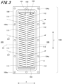
- FIG. 2 is a perspective view illustrating a configuration of a powder capturing device included in the three-dimensional PBF-AM apparatus according to the first embodiment of the present invention. Furthermore, FIG. 3 is a longitudinal sectional view of the powder capturing device illustrated in FIG. 2 , and FIG. 4 is an enlarged view of the portion A in FIG. 3 .
- the powder capturing device 100 includes a first flow path forming unit 101, a second flow path forming unit 102, a support frame 103, and a flange 104. Furthermore, in FIG. 2 , the support frame 103 is transparent in order to be able to confirm the structures of the first flow path forming unit 101 and the second flow path forming unit 102.
- the first flow path forming unit 101 and the second flow path forming unit 102 form gas flow paths 107 continuous from an intake unit 105 to an exhaust unit 106.
- the intake unit 105 is a portion located on the vacuum chamber 12 side.
- the exhaust unit 106 is a portion located on the main pump 132 side.
- the gas flow paths 107 are portions through which the gas sucked from the vacuum chamber 12 to the main pump 132 flows when the gas in the vacuum chamber 12 is evacuated due to the operation of the main pump 132.
- the state in which the gas flow paths 107 are continuous refers to a state in which there is no obstacle that hinders the flow of gas in the middle of the gas flow paths 107, and the gas flow paths 107 are communicated from the intake unit 105 to the exhaust unit 106.
- a porous body such as a mesh-like or fibrous body can be considered.
- the first flow path forming unit 101 includes a plurality of first plate-shaped units 111
- the second flow path forming unit 102 includes a plurality of second plate-shaped units 112.
- Each of the first plate-shaped units 111 is inclined upward to the left in FIG. 3 with respect to a reference axis line K1 (see FIG. 3 ) connecting the intake unit 105 and the exhaust unit 106
- each of the second plate-shaped units 112 is inclined upward to the right in FIG. 3 with respect to the reference axis line K1.
- the first plate-shaped units 111 and the second plate-shaped units 112 are inclined in directions opposite to each other with respect to the reference axis line K1.
- first plate-shaped units 111 and the second plate-shaped units 112 are disposed in a V shape when viewed from the side of the gas flow paths 107 (the Y direction in FIG. 2 ).
- the reference axis line K1 is an axis parallel to the X direction.
- an upper surface 111a and a lower surface 111b which are main surfaces of the first plate-shaped units 111, are in a front-back positional relationship
- an upper surface 112a and a lower surface 112b which are main surfaces of the second plate-shaped units 112 are also in the front-back positional relationship.
- the upper surface 111a and the lower surface 111b of the first plate-shaped units 111 each correspond to the first catching unit.
- the first catching unit is a portion that causes the powder sucked from the intake unit to collide to catch the powder.
- the upper surface 112a and the lower surface 112b of the second plate-shaped units 112 each correspond to the second catching unit.
- the second catching unit is located on a downstream side of the first catching unit in the gas flow path, and is a portion that causes the powder passing through the first flow path forming unit to collide to catch the powder.
- first plate-shaped units 111 and the second plate-shaped units 112 are disposed in a plurality of stages at predetermined intervals in the Z direction. Then, one gas flow path 107 is formed between the first plate-shaped units 111 and the second plate-shaped units 112 disposed on the M th step (M is a natural number) from the top in the Z direction and the first plate-shaped units 111 and the second plate-shaped units 112 disposed on the M+1 th step adjacent thereto. In other words, similarly to the first plate-shaped units 111 and the second plate-shaped units 112, the gas flow paths 107 are formed over a plurality of stages in the Z direction.
- first plate-shaped units 111 and the second plate-shaped units 112 have a drop unit 115 (see FIG. 4 ) for dropping the metal powder 32 into a lower stage.
- the drop unit 115 is provided at a V-shaped bent portion which is a boundary portion between the first plate-shaped units 111 and the second plate-shaped units 112.
- the drop unit 115 is preferably formed in a slit shape elongated in the Y direction.
- the drop unit 115 is not provided in the first plate-shaped units 111 and the second plate-shaped units 112 disposed at the lowermost stage, but is provided in the first plate-shaped units 111 and the second plate-shaped units 112 positioned at an upper stage of the lowermost stage.
- the support frame 103 is a member that supports the plurality of first plate-shaped units 111 constituting the first flow path forming unit 101 and the plurality of second plate-shaped units 112 constituting the second flow path forming unit 102.
- the plurality of first plate-shaped units 111 and the plurality of second plate-shaped units 112 are attached to the inside of the support frame 103.
- the support frame 103 is formed in a lateral U shape or a quadrangular shape when viewed from the X direction in such way to surround the plurality of first plate-shaped units 111 and the plurality of second plate-shaped units 112 from three directions or four directions.
- the flange 104 is a member for attaching the powder capturing device 100 to the exhaust pipe (not illustrated).
- the exhaust pipe to which the powder capturing device 100 is attached is an exhaust pipe that connects the vacuum chamber 12 and the main pump 132.
- the flange 104 is formed in a plate shape elongated in the Z direction.
- the flange 104 is provided with a plurality of attachment holes 104a.
- the attachment holes 104a are holes for attaching the flange 104 to the exhaust pipe (not illustrated) in a fixed state by screwing.
- the exhaust pipe (not illustrated) is provided with a rectangular opening portion into which the first flow path forming unit 101, the second flow path forming unit 102, and the support frame 103 can be inserted and removed; and the flange 104 is attached to the exhaust pipe in such a way to close the opening portion.
- the intake unit 105 is disposed facing the vacuum chamber 12 side
- the exhaust unit 106 is disposed facing the main pump 132 side.
- the first flow path forming unit 101 and the second flow path forming unit 102 are disposed inside the exhaust pipe (not illustrated), and the support frame 103 is disposed in contact with an inner wall surface of the exhaust pipe (not illustrated).
- the first flow path forming unit 101, the second flow path forming unit 102, the support frame 103, and the flange 104 described above are all made of a metal material (for example, stainless steel or the like), and are electrically connected to each other by physical contact. Furthermore, the first flow path forming unit 101 and the second flow path forming unit 102 are electrically connected to a grounding unit 117 (see FIG. 2 ) via the support frame 103 and the flange 104. Moreover, the first flow path forming unit 101 and the second flow path forming unit 102 may be electrically connected directly to the grounding unit 117 without passing through the support frame 103 and the flange 104.
- the powder capturing device 100 mainly has two functions. One is ventilation function and the other is powder capturing function. Each function will be described below.
- the gas in the vacuum chamber 12 When the gas in the vacuum chamber 12 is evacuated by the vacuum pump 13, the gas in the vacuum chamber 12 is sucked by the main pump 132 through the powder capturing device 100 and exhausted from the exhaust port of the main pump 132. At this time, in the portion where the powder capturing device 100 is disposed, the gas flows from the intake unit 105 toward the exhaust unit 106. Furthermore, the gas flows through the gas flow paths 107 formed in a plurality of stages in the Z direction. In the present embodiment, the gas flow paths 107 are continuous from the intake unit 105 to the exhaust unit 106. Therefore, the flow of gas passing through the gas flow paths 107 is not hindered. Accordingly, the gas in the vacuum chamber 12 can be efficiently evacuated.
- the metal powder 32 floating in the vacuum chamber 12 may move toward the powder capturing device 100 by a suction force of the vacuum pump 13 (mainly the main pump 132). In that case, the metal powder 32 moves linearly toward the powder capturing device 100.
- the metal powder 32 collides with the lower surface 111b of the first plate-shaped units 111. As a result, kinetic energy of the metal powder 32 is lost. Therefore, the metal powder 32 can be captured in the first flow path forming unit 101.
- the metal powder 32 may pass through the first flow path forming unit 101 depending on the direction of the metal powder 32 moving toward the powder capturing device 100.
- the metal powder 32 having passed through the first flow path forming unit 101 collides with the upper surface 112a of the second plate-shaped units 112, and accordingly, the kinetic energy of the metal powder 32 is lost. Therefore, the metal powder 32 can be captured in the second flow path forming unit 102.
- the powder capturing device 100 captures the metal powder 32 by collision with the first plate-shaped units 111 or the second plate-shaped units 112. Therefore, by disposing the powder capturing device 100 on the intake side of the main pump 132, it is possible to suppress the intrusion of the metal powder 32 into the main pump 132. In addition, since the roughing pump 131 is disposed on the exhaust side of the main pump 132, the intrusion of the metal powder 32 into the roughing pump 131 can be suppressed by capturing the metal powder 32 using the powder capturing device 100 as described above.
- the powder capturing device 100 can suppress the intrusion of powder into the vacuum pump 13 without reducing the exhaust efficiency as much as possible by the two functions described above.
- the first plate-shaped units 111 and the second plate-shaped units 112 are inclined in different directions from each other with respect to the reference axis line K1 connecting the intake unit 105 and the exhaust unit 106. Therefore, the metal powder 32 can collide with the first plate-shaped units 111 or the second plate-shaped units 112 without hindering the flow of gas.
- the first plate-shaped units 111 and the second plate-shaped units 112 are disposed in a V shape. Therefore, the metal powder 32 captured due to the collision with the first plate-shaped units 111 or the second plate-shaped units 112 can be retained in the powder capturing device 100 without rolling down to the vacuum chamber 12 side or the main pump 132 side.
- the powder capturing device 100 has the drop unit 115 for dropping the metal powder 32 captured due to the collision with the first plate-shaped units 111 or the second plate-shaped units 112 into the lower stage. Therefore, as illustrated in FIG. 4 described above, the metal powder 32 that has collided with the lower surface 111b of the first plate-shaped units 111 falls in a B2 direction, then moves in a B3 direction along the upper surface 111a of the first plate-shaped units 111, and falls in a B4 direction through the drop unit 115.
- the metal powder 32 that has passed through the first flow path forming unit 101 and collided with the upper surface 112a of the second plate-shaped units 112 moves along the upper surface 112a of the second plate-shaped units 112 and then falls through the drop unit 115. Therefore, the metal powder 32 captured due to the collision with the first plate-shaped units 111 or the second plate-shaped units 112 can be collected at the boundary portion (the bent portion) between the first plate-shaped units 111 and the second plate-shaped units 112 disposed in the lower stage (the lowermost stage in the present embodiment). As a result, it is possible to easily perform a recovery operation of the captured metal powder 32 and a cleaning operation after the recovery.
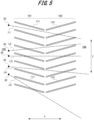
- the metal powder 32 moving toward the powder capturing device 100 enters at any angle from any position in the Z direction without being limited to the B1 direction illustrated in FIG. 4 . Therefore, in the present embodiment, as a preferred aspect, the plurality of first plate-shaped units 111 and the plurality of second plate-shaped units 112 are disposed in a state where the facing cannot be linearly expected. This matter will be described with reference to FIG. 5 .
- the state in which the facing cannot be linearly expected refers to a state in which at least one plate-shaped unit of the first plate-shaped units 111 and the second plate-shaped units 112 is present on any straight line connecting the intake unit 105 and the exhaust unit 106.
- FIG. 5 illustrates five straight lines L1, L2, L3, L4, and L5 as an example of any straight line.
- the five straight lines L1, L2, L3, L4, and L5 are straight lines having different positions in the Z direction on the intake unit 105 side.
- the five straight lines L1, L2, L3, L4, and L5 have different angles formed by the reference axis line K1 described above (see FIG. 3 ).
- the first plate-shaped units 111 are not present and only the second plate-shaped units 112 are present on the straight line L1. Therefore, the metal powder 32 entering along the straight line L1 passes through the first flow path forming unit 101, then collides with the second plate-shaped units 112 and are captured.
- the second plate-shaped units 112 are not present, and only the first plate-shaped units 111 are present on the straight line L2. Accordingly, the metal powder 32 entering along the straight line L2 is captured due to the collision with the first plate-shaped units 111.
- first plate-shaped units 111 and the second plate-shaped units 112 are present on the straight line L3. Accordingly, the metal powder 32 entering along the straight line L3 is captured due to the collision with the first plate-shaped units 111.
- the first plate-shaped units 111 are not present, and only the second plate-shaped units 112 are present on the straight line L4. Accordingly, the metal powder 32 entering along the straight line L4 passes through the first flow path forming unit 101, then collides with the second plate-shaped units 112, and are captured.
- the second plate-shaped units 112 are not present, and only the first plate-shaped units 111 are present on the straight line L5. Accordingly, the metal powder 32 entering along the straight line L5 is captured due to the collision with the first plate-shaped units 111.
- At least one plate-shaped unit of the first plate-shaped units 111 and the second plate-shaped units 112 is present on any straight line connecting the intake unit 105 and the exhaust unit 106. Therefore, the metal powder 32 entering the powder capturing device 100 from any direction can be reliably captured due to the collision with the first plate-shaped units 111 or the second plate-shaped units 112.
- the first flow path forming unit 101 and the second flow path forming unit 102 are electrically connected to the grounding unit 117 via the support frame 103 and the flange 104. Accordingly, electric charges of the metal powder 32 can be removed by causing the metal powder 32 to collide with the first plate-shaped units 111 or the second plate-shaped units 112. In addition, the electric charges can be released to the grounding unit 117 such that the first plate-shaped units 111 and the second plate-shaped units 112 are not charged due to the collision with the metal powder 32.
- the second embodiment is different from the first embodiment described above in the configuration of the powder capturing device.
- FIG. 6 is a perspective view illustrating a configuration of a powder capturing device included in the three-dimensional PBF-AM apparatus according to the second embodiment of the present invention
- FIG. 7 is a longitudinal sectional view of the powder capturing device illustrated in FIG. 6 .
- a powder capturing device 200 includes a first flow path forming unit 201, a second flow path forming unit 202, a third flow path forming unit 203, a support frame 204, and a flange 205.
- the support frame 204 is transparent in order to be able to confirm the structures of the first flow path forming unit 201, the second flow path forming unit 202, and the third flow path forming unit 203.
- the first flow path forming unit 201, the second flow path forming unit 202, and the third flow path forming unit 203 form a gas flow path 208 that is continuous from an intake unit 206 located on the vacuum chamber 12 side to an exhaust unit 207 located on the main pump 132 side.
- the gas flow path 208 is a portion through which the gas sucked from the vacuum chamber 12 to the main pump 132 flows when the gas in the vacuum chamber 12 is evacuated due to the operation of the main pump 132.
- the first flow path forming unit 201 is constituted by one first plate-shaped unit 211
- the second flow path forming unit 202 is constituted by one second plate-shaped unit 212
- the third flow path forming unit 203 is constituted by one third plate-shaped unit 213.
- Each of the plate-shaped units 211, 212, and 213 is formed in a rectangular shape when viewed from the X direction (a front surface).
- the first plate-shaped unit 211, the second plate-shaped unit 212, and the third plate-shaped unit 213 are disposed at predetermined intervals in the X direction.
- first plate-shaped unit 211 and third plate-shaped unit 213 are disposed in a state of vertically rising from a lower side portion 204b of the support frame 204, and the second plate-shaped unit 212 is disposed in a state of vertically hanging from an upper side portion 204a of the support frame 204.
- the first plate-shaped unit 211 is disposed in a direction orthogonal to a reference axis line K2 (see FIG. 7 ) connecting the intake unit 206 and the exhaust unit 207, and is disposed to be biased downward in the Z direction that is a direction orthogonal to the reference axis line K2.
- the direction orthogonal to the reference axis line K2 refers to a state parallel to a YZ plane.
- the first plate-shaped unit 211 has a first ventilation unit 221 formed on an upper side opposite to a biasing direction of the first plate-shaped unit 211 in the Z direction.
- the first ventilation unit 221 is a portion that allows the gas to flow in the first flow path forming unit 201.
- the first ventilation unit 221 is formed between an upper end portion of the first plate-shaped unit 211 and the upper side portion 204a of the support frame 204 facing the upper end portion.
- a main surface 211a of the first plate-shaped unit 211 is disposed to face the intake unit 206 side.
- the main surface 211a of the first plate-shaped unit 211 corresponds to the first catching unit.
- the first catching unit is a portion that causes the powder sucked from the intake unit to collide to catch the powder.
- the second plate-shaped unit 212 is disposed on the downstream side of the gas flow path 208 with respect to the first plate-shaped unit 211.
- the second plate-shaped unit 212 is disposed on the side opposite to the first plate-shaped unit 211 in the Z direction, that is, biasedly on the upper side.
- the second plate-shaped unit 212 forms a second ventilation unit 222 on the lower side opposite to the biasing direction of the second plate-shaped unit 212 in the Z direction.
- the second ventilation unit 222 is a portion that allows the gas to flow in the second flow path forming unit 202.
- the second ventilation unit 222 is formed between the lower end portion of the second plate-shaped unit 212 and the lower side portion 204b of the support frame 204 facing the lower end portion.
- the lower end portion of the second plate-shaped unit 212 is located below the upper end portion of the first plate-shaped unit 211. Accordingly, the first plate-shaped unit 211 and the second plate-shaped unit 212 are disposed in a state of partially overlapping in the Z direction.
- a main surface 212a of the second plate-shaped unit 212 is disposed to face the intake unit 206 side.
- the main surface 212a of the second plate-shaped unit 212 corresponds to the second catching unit.
- the second catching unit is located on the downstream side of the first catching unit in the gas flow path, and is a portion that causes the powder passing through the first flow path forming unit to collide to catch the powder.
- the third plate-shaped unit 213 is disposed on the downstream side of the gas flow path 208 with respect to the second plate-shaped unit 212.
- the third plate-shaped unit 213 is disposed on the side opposite to the second plate-shaped unit 212 in the Z direction, that is, biasedly to the lower side.
- the third plate-shaped unit 213 forms a third ventilation unit 223 on an upper side opposite to the biasing direction of the third plate-shaped unit 213 in the Z direction.
- the third ventilation unit 223 is a portion that allows the gas to flow in the third flow path forming unit 203.
- the third ventilation unit 223 is formed between the upper end portion of the third plate-shaped unit 213 and the upper side portion 204a of the support frame 204 facing the upper end portion. Furthermore, the upper end portion of the third plate-shaped unit 213 is positioned above the lower end portion of the second plate-shaped unit 212. Accordingly, the second plate-shaped unit 212 and the third plate-shaped unit 213 are disposed in a state of partially overlapping in the Z direction. A main surface 213a of the third plate-shaped unit 213 is disposed to face the intake unit 206 side. The main surface 213a of the third plate-shaped unit 213 corresponds to a third catching unit. The third catching unit is a portion that is located on the downstream side of the second catching unit in the gas flow path and causes the powder passing through the second flow path forming unit to collide to catch the powder.
- the gas flow path 208 is formed in such a way to pass through the first ventilation unit 221, the second ventilation unit 222, and the third ventilation unit 223. Furthermore, as illustrated in FIG. 7 , the gas flow path 208 is bent in a U shape.
- the support frame 204 is a member that supports the first plate-shaped unit 211 constituting the first flow path forming unit 201, the second plate-shaped unit 212 constituting the second flow path forming unit 202, and the third plate-shaped unit 213 constituting the third flow path forming unit 203.
- the first plate-shaped unit 211, the second plate-shaped unit 212, and the third plate-shaped unit 213 are respectively attached to the inside of the support frame 204.
- the support frame 204 is formed in a lateral U-shape or a quadrangular shape as viewed from the X direction in such a way to surround the first plate-shaped unit 211, the second plate-shaped unit 212, and the third plate-shaped unit 213 from three directions or four directions.
- the flange 205 is a member for attaching the powder capturing device 200 to the exhaust pipe (not illustrated).
- the exhaust pipe to which the powder capturing device 200 is attached is an exhaust pipe that connects the vacuum chamber 12 and the main pump 132.
- the flange 205 is formed in a plate shape elongated in the Z direction.
- the flange 205 is provided with a plurality of attachment holes 205a.
- the attachment holes 205a are holes for attaching the flange 205 to the exhaust pipe (not illustrated) in a fixed state by screwing.
- the exhaust pipe (not illustrated) is provided with a rectangular opening portion into which the first flow path forming unit 201, the second flow path forming unit 202, the third flow path forming unit 203, and the support frame 204 can be inserted and removed; and the flange 205 is attached to the exhaust pipe in such a way to close the opening portion.
- the intake unit 206 is disposed facing the vacuum chamber 12 side, and the exhaust unit 207 is disposed facing the main pump 132 side. Furthermore, the first flow path forming unit 201, the second flow path forming unit 202, and the third flow path forming unit 203 are disposed inside the exhaust pipe (not illustrated), and the support frame 204 is disposed in contact with the inner wall surface of the exhaust pipe (not illustrated). As a result, the gas flowing through the exhaust pipe due to the operation of the main pump 132 passes through the gas flow path 208 of the powder capturing device 200.
- the first flow path forming unit 201, the second flow path forming unit 202, the third flow path forming unit 203, the support frame 204, and the flange 205 described above are all made of a metal material (for example, stainless steel or the like), and are electrically connected to each other by physical contact. Furthermore, the first flow path forming unit 201, the second flow path forming unit 202, and the third flow path forming unit 203 are electrically connected to a grounding unit 217 (see FIG. 6 ) via the support frame 204 and the flange 205. Moreover, the first flow path forming unit 201, the second flow path forming unit 202, and the third flow path forming unit 203 may be electrically connected directly to the grounding unit 217 without passing through the support frame 204 and the flange 205.
- a metal material for example, stainless steel or the like
- the gas in the vacuum chamber 12 When the gas in the vacuum chamber 12 is evacuated by the vacuum pump 13, the gas in the vacuum chamber 12 is sucked by the main pump 132 through the powder capturing device 200 and exhausted from the exhaust port of the main pump 132. At this time, in the portion where the powder capturing device 200 is disposed, the gas flows from the intake unit 206 toward the exhaust unit 207. Furthermore, the gas flows through the gas flow path 208 formed by the first flow path forming unit 201, the second flow path forming unit 202, and the third flow path forming unit 203. In the present embodiment, the gas flow path 208 is continuous from the intake unit 206 to the exhaust unit 207. Therefore, the flow of gas passing through the gas flow path 208 is not hindered. Accordingly, the gas in the vacuum chamber 12 can be efficiently evacuated.
- the metal powder 32 floating in the vacuum chamber 12 may move toward the powder capturing device 200 due to the suction force of the vacuum pump 13 (mainly the main pump 132). In that case, the metal powder 32 moves linearly toward the powder capturing device 200.
- the metal powder 32 collides with the main surface 211a of the first plate-shaped unit 211. As a result, since the kinetic energy of the metal powder 32 is lost, the metal powder 32 can be captured in the first flow path forming unit 201.
- the metal powder 32 moves in a C2 direction toward the powder capturing device 200, the metal powder 32 passes through the first ventilation unit 221 of the first flow path forming unit 201.
- the metal powder 32 having passed through the first ventilation unit 221 collides with the main surface 212a of the second plate-shaped unit 212, and accordingly, the kinetic energy of the metal powder 32 is lost. Therefore, the metal powder 32 can be captured in the second flow path forming unit 202.
- the metal powder 32 moves in a C3 direction toward the powder capturing device 200, the metal powder 32 sequentially passes through the first ventilation unit 221 of the first flow path forming unit 201 and the second ventilation unit 222 of the second flow path forming unit 202.
- the metal powder 32 having passed through the second ventilation unit 222 collides with the main surface 213a of the third plate-shaped unit 213, and accordingly, the kinetic energy of the metal powder 32 is lost. Therefore, the metal powder 32 can be captured in the third flow path forming unit 203.
- the powder capturing device 200 captures the metal powder 32 due to the collision with the first plate-shaped unit 211, the second plate-shaped unit 212, or the third plate-shaped unit 213. Therefore, by disposing the powder capturing device 200 on the intake side of the main pump 132, it is possible to suppress the intrusion of the metal powder 32 into the main pump 132 and the roughing pump 131.
- the powder capturing device 200 can suppress the intrusion of powder into the vacuum pump 13 without reducing the exhaust efficiency as much as possible by the two functions described above.
- the first plate-shaped unit 211 and the second ventilation unit 222 are disposed to be biased in opposite directions to each other and partially overlapped in the Z direction. Therefore, the metal powder 32 can collide with the first plate-shaped unit 211 or the second plate-shaped unit 212 without hindering the flow of gas.
- the third flow path forming unit 203 is provided in addition to the first flow path forming unit 201 and the second flow path forming unit 202. Accordingly, this makes it possible to enhance the function of capturing the metal powder 32.
- the gas flow path 208 is formed in such a way to pass through the first ventilation unit 221, the second ventilation unit 222, and the third ventilation unit 223. Accordingly, this makes it possible to bend the gas flow path 208 while maintaining continuity of the gas flow path 208.
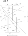
- the metal powder 32 moving toward the powder capturing device 200 enters at an arbitrary angle from an arbitrary position in the Z direction without being limited to the C1 direction, the C2 direction, and the C3 direction illustrated in FIG. 7 . Therefore, in the present embodiment, as a preferred aspect, the first plate-shaped unit 211, the second plate-shaped unit 212, and the third plate-shaped unit 213 are disposed in a state where the facing cannot be linearly expected. This matter will be described with reference to FIG. 8 .
- the state in which the facing cannot be expected linearly refers to a state in which at least one plate-shaped unit among the first plate-shaped unit 211, the second plate-shaped unit 212, and the third plate-shaped unit 213 is present on the arbitrary straight line connecting the intake unit 206 and the exhaust unit 207.
- FIG. 8 illustrates five straight lines L11, L12, L13, L14, and L15 as an example of an arbitrary straight line.
- the five straight lines L11, L12, L13, L14, and L15 are straight lines having different positions in the Z direction on the intake unit 206 side.
- the five straight lines L11, L12, L13, L14, and L15 have different angles formed by the reference axis line K2 (see FIG. 7 ) .
- the first plate-shaped unit 211 and the third plate-shaped unit 213 are not present, and only the second plate-shaped unit 212 is present on the straight line L11. Therefore, the metal powder 32 entering along the straight line L11 passes through the first flow path forming unit 201 and then is captured due to the collision with the second plate-shaped unit 212.
- the first plate-shaped unit 211 is not present, and the second plate-shaped unit 212 and the third plate-shaped unit 213 are present on the straight line L12. Therefore, the metal powder 32 entering along the straight line L12 passes through the first flow path forming unit 201 and then is captured due to the collision with the second plate-shaped unit 212.
- the first plate-shaped unit 211 and the second plate-shaped unit 212 are not present, and only the third plate-shaped unit 213 is present on the straight line L13. Therefore, the metal powder 32 entering along the straight line L13 passes through the first flow path forming unit 201 and the second flow path forming unit 202, and then is captured due to the collision with the third plate-shaped unit 213.
- the first plate-shaped unit 211 and the third plate-shaped unit 213 are not present, and only the second plate-shaped unit 212 is present on the straight line L14. Therefore, the metal powder 32 entering along the straight line L14 passes through the first flow path forming unit 201 and then is captured due to the collision with the second plate-shaped unit 212.
- the second plate-shaped unit 212 is not present, and the first plate-shaped unit 211 and the third plate-shaped unit 213 are present on the straight line L15. Therefore, the metal powder 32 entering along the straight line L15 is captured due to the collision with the first plate-shaped unit 111.
- At least one plate-shaped unit of the first plate-shaped unit 211, the second plate-shaped unit 212, and the third plate-shaped unit 213 is present on an arbitrary straight line connecting the intake unit 206 and the exhaust unit 207. Therefore, the metal powder 32 entering the powder capturing device 200 from an arbitrary direction can be reliably captured due to the collision with the first plate-shaped unit 211, the second plate-shaped unit 212, or the third plate-shaped unit 213.
- the first flow path forming unit 201, the second flow path forming unit 202, and the third flow path forming unit 203 are electrically connected to the grounding unit 217 via the support frame 204 and the flange 205. Therefore, by causing the metal powder 32 to collide with the first plate-shaped unit 211, the second plate-shaped unit 212, or the third plate-shaped unit 213, the electric charges of the metal powder 32 can be removed. In addition, the electric charges can be released to the grounding unit 217 such that the first plate-shaped unit 211, the second plate-shaped unit 212, and the third plate-shaped unit 213 are not charged due to the collision with the metal powder 32.
- the third embodiment is different from the first embodiment and the second embodiment described above in the configuration of the powder capturing device.
- FIG. 9 is a perspective view illustrating a configuration of the powder capturing device included in the three-dimensional PBF-AM apparatus according to the third embodiment of the present invention.
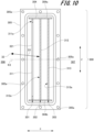
- FIG. 10 is a longitudinal sectional view of the powder capturing device shown in FIG. 9
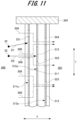
- FIG. 11 is a transverse sectional view of the powder capturing device shown in FIG. 9 .
- a powder capturing device 300 includes a first flow path forming unit 301, a second flow path forming unit 302, a third flow path forming unit 303, a support frame 304, and a flange 305. Furthermore, in FIG. 9 , the support frame 304 is made transparent in order to be able to confirm the structures of the first flow path forming unit 301, the second flow path forming unit 302, and the third flow path forming unit 303.
- the first flow path forming unit 301, the second flow path forming unit 302, and the third flow path forming unit 303 form a gas flow path 308 that is continuous from an intake unit 306 located on the vacuum chamber 12 side to an exhaust unit 307 located on the main pump 132 side.
- the gas flow path 208 is a portion through which the gas sucked from the vacuum chamber 12 to the main pump 132 flows when the gas in the vacuum chamber 12 is evacuated due to the operation of the main pump 132.
- the first flow path forming unit 301 is constituted by one first plate-shaped unit 311, the second flow path forming unit 302 is constituted by one second plate-shaped unit 312, and the third flow path forming unit 303 is constituted by one third plate-shaped unit 313.
- Each of the plate-shaped units 311, 312, and 313 is formed in a rectangular shape when viewed from the X direction (the front surface).
- the first plate-shaped unit 311, the second plate-shaped unit 312, and the third plate-shaped unit 313 are disposed at predetermined intervals in the X direction.
- each plate-shaped unit 311, 312, and 313 is disposed in a vertically standing state between an upper side portion 304a and a lower side portion 304b of the support frame 304 in the Z direction.
- the first plate-shaped unit 311 is disposed in a direction orthogonal to a reference axis line K3 (see FIG. 10 ) connecting the intake unit 306 and the exhaust unit 307.
- the direction orthogonal to the reference axis line K3 refers to a state parallel to the YZ plane.
- the first plate-shaped unit 311 is provided with a plurality of first ventilation ports 321.
- the plurality of first ventilation ports 321 are arranged at predetermined intervals in the Y direction.
- Each of the first ventilation ports 321 is a portion that allows the gas to flow.
- Each of the first ventilation ports 321 is opened in a rectangular shape elongated in the Z direction when viewed from the X direction.
- a main surface 311a of the first plate-shaped unit 311 is disposed to face the intake unit 306 side.
- the main surface 311a of the first plate-shaped unit 311 corresponds to the first catching unit.
- the first catching unit is a portion excluding the first ventilation port, and is a portion that causes the powder sucked from the intake unit to collide and then catches the powder.
- the second plate-shaped unit 312 is disposed on the downstream side of the first plate-shaped unit 311 in the gas flow path 308 in such a way to face the first plate-shaped unit 311.
- the second plate-shaped unit 312 is provided with a plurality of second ventilation ports 322.
- the plurality of second ventilation ports 322 are arranged at predetermined intervals in the Y direction.
- Each of the second ventilation ports 322 is a portion that allows the gas to flow.
- Each of the second ventilation ports 322 is opened in a rectangular shape elongated in the Z direction when viewed from the X direction.
- the second ventilation ports 322 are provided to be shifted in positions from the first ventilation ports 321 in a width direction (the Y direction) of the gas flow path 308.
- a main surface 312a of the second plate-shaped unit 312 is disposed to face the intake unit 306 side.
- the main surface 312a of the second plate-shaped unit 312 corresponds to the second catching unit.
- the second catching unit is a portion excluding the second ventilation port, is located on the downstream side of the gas flow path with respect to the first catching unit, and is a portion that causes the powder passing through the second flow path forming unit to collide and then catches the powder.
- the third plate-shaped unit 313 is disposed on the downstream side of the second plate-shaped unit 312 in the gas flow path 308 in such a way to face the second plate-shaped unit 312.
- the third plate-shaped unit 313 is provided with a plurality of third ventilation ports 323.
- the plurality of third ventilation ports 323 is arranged at predetermined intervals in the Y direction.
- Each of the third ventilation ports 323 is a portion that allows the gas to flow.
- Each of the third ventilation ports 323 is opened in a rectangular shape elongated in the Z direction when viewed from the X direction.
- the first ventilation ports 321, the second ventilation ports 322, and the third ventilation ports 323 are opened in the same shape. Furthermore, as illustrated in FIG.
- the third ventilation ports 323 are provided to be shifted in positions from the second ventilation ports 322 in the width direction (the Y direction) of the gas flow path 308.
- a main surface 313a of the third plate-shaped unit 313 is disposed to face the intake unit 306 side.
- the main surface 313a of the third plate-shaped unit 313 corresponds to the third catching unit.
- the third catching unit is a portion excluding the third ventilation port, is located on the downstream side of the gas flow path with respect to the second catching unit, and is a portion that causes powder passing through the second flow path forming unit to collide and then catches the powder.
- the gas flow path 308 is formed in such a way to pass through the first ventilation ports 321, the second ventilation ports 322, and the third ventilation ports 323.
- the gas flow path 308 is bent in a crank shape.
- the support frame 304 is a member that supports the first plate-shaped unit 311 constituting the first flow path forming unit 301, the second plate-shaped unit 312 constituting the second flow path forming unit 302, and the third plate-shaped unit 313 constituting the third flow path forming unit 303.
- the first plate-shaped unit 311, the second plate-shaped unit 312, and the third plate-shaped unit 313 are attached to the inside of the support frame 304.
- the support frame 304 is formed in a lateral U-shape or a quadrangular shape as viewed from the X direction in such a way to surround the first plate-shaped unit 311, the second plate-shaped unit 312, and the third plate-shaped unit 313 from three directions or four directions.
- the flange 305 is a member for attaching the powder capturing device 300 to the exhaust pipe (not illustrated).
- the exhaust pipe to which the powder capturing device 300 is attached is an exhaust pipe that connects the vacuum chamber 12 and the main pump 132.
- the flange 305 is formed in a plate shape elongated in the Z direction.
- the flange 305 is provided with a plurality of attachment holes 305a.
- the attachment holes 305a are holes for attaching the flange 305 to the exhaust pipe (not illustrated) in a fixed state by screwing.
- the exhaust pipe (not illustrated) is provided with a rectangular opening portion through which the first flow path forming unit 301, the second flow path forming unit 302, the third flow path forming unit 303, and the support frame 304 can be inserted and removed; and the flange 305 is attached to the exhaust pipe in such a way to close the opening portion.
- the intake unit 306 is disposed facing the vacuum chamber 12 side
- the exhaust unit 307 is disposed facing the main pump 132 side.
- the first flow path forming unit 301, the second flow path forming unit 302, and the third flow path forming unit 303 are disposed inside the exhaust pipe (not illustrated), and the support frame 304 is disposed in contact with the inner wall surface of the exhaust pipe (not illustrated).
- the first flow path forming unit 301, the second flow path forming unit 302, the third flow path forming unit 303, the support frame 304, and the flange 305 described above are all made of a metal material (for example, stainless steel or the like), and are electrically connected to each other by physical contact. Furthermore, the first flow path forming unit 301, the second flow path forming unit 302, and the third flow path forming unit 303 are electrically connected to a grounding unit 317 (see FIG. 9 ) via the support frame 304 and the flange 305. Moreover, the first flow path forming unit 301, the second flow path forming unit 302, and the third flow path forming unit 303 may be electrically connected directly to the grounding unit 317 without passing through the support frame 304 and the flange 305.
- a metal material for example, stainless steel or the like
- the gas in the vacuum chamber 12 When the gas in the vacuum chamber 12 is evacuated by the vacuum pump 13, the gas in the vacuum chamber 12 is sucked by the main pump 132 through the powder capturing device 300 and exhausted from the exhaust port of the main pump 132. At this time, in the portion where the powder capturing device 300 is disposed, the gas flows from the intake unit 306 toward the exhaust unit 307. Furthermore, the gas flows through the gas flow path 308 formed by the first flow path forming unit 301, the second flow path forming unit 302, and the third flow path forming unit 303. In the present embodiment, the gas flow path 308 is continuous from the intake unit 306 to the exhaust unit 307. Therefore, the flow of gas passing through the gas flow path 308 is not hindered. Accordingly, the gas in the vacuum chamber 12 can be efficiently evacuated.
- the metal powder 32 floating in the vacuum chamber 12 may move toward the powder capturing device 300 due to the suction force of the vacuum pump 13 (mainly the main pump 132). In that case, the metal powder 32 moves linearly toward the powder capturing device 300.
- the metal powder 32 collides with the main surface 311a of the first plate-shaped unit 311. Accordingly, since the kinetic energy of the metal powder 32 is lost, the metal powder 32 can be captured in the first flow path forming unit 301.
- the metal powder 32 moves in a D2 direction toward the powder capturing device 200, the metal powder 32 passes through the first ventilation ports 321 of the first plate-shaped unit 311 and collides with the main surface 312a of the second plate-shaped unit 312. Accordingly, since the kinetic energy of the metal powder 32 is lost, the metal powder 32 can be captured in the second flow path forming unit 302. Furthermore, although not illustrated, depending on the direction of the metal powder 32 moving toward the powder capturing device 300, the metal powder 32 may collide with the main surface 313a of the third plate-shaped unit 313 through the first ventilation ports 321 and the second ventilation ports 322. In this case, the metal powder 32 can be captured in the third flow path forming unit 303.
- the powder capturing device 300 captures the metal powder 32 by the collision with the first plate-shaped unit 311, the second plate-shaped unit 312, and the third plate-shaped unit 313. Therefore, by disposing the powder capturing device 300 on the intake side of the main pump 132, it is possible to suppress the intrusion of the metal powder 32 into the main pump 132 and the roughing pump 131.
- the powder capturing device 300 can suppress the intrusion of powder into the vacuum pump 13 without reducing the exhaust efficiency as much as possible by the two functions described above.
- the plurality of first ventilation ports 321 provided in the first plate-shaped unit 311 and the plurality of second ventilation ports 322 provided in the second plate-shaped unit 312 are disposed to be shifted in positions in the width direction (the Y direction) of the gas flow path 208.
- the metal powder 32 can collide with the first plate-shaped unit 311 or the second plate-shaped unit 312 without hindering the flow of gas.
- a third flow path forming unit 303 is provided in addition to the first flow path forming unit 301 and the second flow path forming unit 302. Accordingly, this makes it possible to enhance the function of capturing the metal powder 32.
- the gas flow path 308 is formed in such a way to pass through the first ventilation ports 321, the second ventilation ports 322, and the third ventilation ports 323. As a result, the gas flow path 308 can be bent while maintaining the continuity of the gas flow path 308.
- the metal powder 32 moving toward the powder capturing device 300 enters at an arbitrary angle from an arbitrary position in the Y direction without being limited to the D1 direction and the D2 direction illustrated in FIG. 11 . Therefore, in the present embodiment, as a preferred aspect, the first plate-shaped unit 311, the second plate-shaped unit 312, and the third plate-shaped unit 313 are disposed in a state where the facing cannot be linearly expected. This matter will be described with reference to FIG. 12 .
- the state in which the facing cannot be linearly expected refers to a state in which at least one plate-shaped unit among the first plate-shaped unit 311, the second plate-shaped unit 312, and the third plate-shaped unit 313 is present on an arbitrary straight line connecting the intake unit 306 and the exhaust unit 307.
- FIG. 11 illustrates five straight lines L21, L22, L23, L24, and L25 as an example of an arbitrary straight line.
- the five straight lines L21, L22, L23, L24, and L25 are straight lines having different positions in the Y direction on the intake unit 306 side.
- the five straight lines L21, L22, L23, L24, and L25 have different angles formed by the reference axis line K3 (see FIG.
- the plate-shaped units having the ventilation ports are not present on the straight line.
- the main surface (catching unit) of any plate-shaped unit is present on a straight line, the plate-shaped units having the main surfaces are not present on the straight line.
- the first plate-shaped unit 311 and the third plate-shaped unit 313 are not present, and only the second plate-shaped unit 312 is present on the straight line L21. Therefore, the metal powder 32 entering along the straight line L11 is captured due to the collision with the main surface 312a of the second plate-shaped unit 312 after passing through the first ventilation ports 321.
- the second plate-shaped unit 312 and the third plate-shaped unit 313 are not present, and only the first plate-shaped unit 311 is present on the straight line L22. Therefore, the metal powder 32 entering along the straight line L22 is captured by colliding with the main surface 311a of the first plate-shaped unit 311.
- the first plate-shaped unit 311 and the second plate-shaped unit 312 are not present, and only the third plate-shaped unit 313 is present on the straight line L23. Therefore, the metal powder 32 entering along the straight line L23 passes through the first ventilation ports 321 and the second ventilation ports 322, and then is captured due to the collision with the main surface 313a of the third plate-shaped unit 313.
- the first plate-shaped unit 311 and the second plate-shaped unit 312 are not present, and only the third plate-shaped unit 313 is present on the straight line L24. Therefore, the metal powder 32 entering along the straight line L24 passes through the first ventilation ports 321 and the second ventilation ports 322, and then is captured due to the collision with the main surface 313a of the third plate-shaped unit 313.
- the first plate-shaped unit 311 is not present, and the second plate-shaped unit 312 and the third plate-shaped unit 313 are present on the straight line L25. Therefore, the metal powder 32 entering along the straight line L25 is captured due to the collision with the main surface 312a of the second plate-shaped unit 312 after passing through the first ventilation ports 321.
- At least one plate-shaped unit of the first plate-shaped unit 311, the second plate-shaped unit 312, and the third plate-shaped unit 313 is present on an arbitrary straight line connecting the intake unit 306 and the exhaust unit 307. Therefore, the metal powder 32 entering the powder capturing device 200 from an arbitrary direction can be reliably captured due to the collision with the first plate-shaped unit 311, the second plate-shaped unit 312, or the third plate-shaped unit 313.
- the first flow path forming unit 301, the second flow path forming unit 302, and the third flow path forming unit 303 are electrically connected to the grounding unit 317 via the support frame 304 and the flange 305. Therefore, by causing the metal powder 32 to collide with the first plate-shaped unit 311, the second plate-shaped unit 312, or the third plate-shaped unit 313, the electric charges of the metal powder 32 can be removed. In addition, the electric charges can be released to the grounding unit 317 such that the first plate-shaped unit 311, the second plate-shaped unit 312, and the third plate-shaped unit 313 are not charged due to the collision with the metal powder 32.
- the technical scope of the present invention is not limited to the embodiment described above, and includes a mode in which various modifications and improvements are added within a range in which specific effects obtained by the constituent elements of the invention and the combination thereof can be derived.
- the first plate-shaped units 111 and the second plate-shaped units 112 are disposed in a V shape when viewed from the side of the gas flow paths 107, but the present invention is not limited thereto, and the first plate-shaped units and the second plate-shaped units may be disposed in a U shape instead of a V shape.
- the support frame 103 and the flange 104 are provided in order to dispose the first flow path forming unit 101 and the second flow path forming unit 102 inside the exhaust pipe (not illustrated).
- the present invention is not limited thereto, and various modifications can be made to the configuration for attaching the first flow path forming unit 101 and the second flow path forming unit 102 to the inside of the exhaust pipe. In this respect, the same also applies to the second embodiment and the third embodiment.
- the first ventilation unit 221, the second ventilation unit 222, and the third ventilation unit 223 are formed by arranging the first plate-shaped unit 211, the second plate-shaped unit 212, and the third plate-shaped unit 213 to be biased in the Z direction, but the present invention is not limited thereto.
- the first ventilation unit 221, the second ventilation unit 222, and the third ventilation unit 223 may be formed by arranging the first plate-shaped unit 211, the second plate-shaped unit 212, and the third plate-shaped unit 213 to be biased in the Y direction.
- the gas flow path 208 is formed by the three flow path forming units 201, 202, and 203, but the present invention is not limited thereto, and the gas flow path may be formed by two or four or more flow path forming units.
- the gas flow path may be formed by two or four or more flow path forming units.
- the plurality of first ventilation ports 321 are provided in the first plate-shaped unit 311, but the number of the first ventilation ports 321 may be one. Then, the opening shape and opening dimension of the first ventilation ports 321 can be arbitrarily changed. In this respect, the same also applies to a case where the second ventilation ports 322 are provided in the second plate-shaped unit 312 or a case where the third ventilation ports 323 are provided in the third plate-shaped unit 313.
Landscapes
- Chemical & Material Sciences (AREA)
- Engineering & Computer Science (AREA)
- Manufacturing & Machinery (AREA)
- Materials Engineering (AREA)
- Chemical Kinetics & Catalysis (AREA)
- Life Sciences & Earth Sciences (AREA)
- Sustainable Development (AREA)
- Physics & Mathematics (AREA)
- Plasma & Fusion (AREA)
- Powder Metallurgy (AREA)
Abstract
Description
- The present invention relates to a three-dimensional powder bed fusion additive manufacturing (PBF-AM) apparatus.
- In recent years, there has been known a three-dimensional powder bed fusion additive manufacturing (PBF-AM) apparatus that irradiates metal powder spread in layers with an electron beam to melt and solidify the metal powder, and sequentially stacks solidified layers to form a manufactured object having a three-dimensional structure.
- In this type of three-dimensional PBF-AM apparatus, individual powder particles are charged by irradiation of the electron beam, and a phenomenon in which powders are scattered in a smoke form by Coulomb repulsive force, that is, a phenomenon called smoke may occur (see Patent Literature 1).
- Patent Literature 1:
JP 2019-7051 A - In the three-dimensional PBF-AM apparatus, an inside of a vacuum chamber is maintained in a vacuum state by a vacuum pump to build the manufactured object. Therefore, when a smoke phenomenon occurs during building, the powder scattered by smoke may enter the vacuum pump and adversely affect the vacuum pump.
- In addition, when a mesh-like or fibrous filter is disposed on an intake side of the vacuum pump in order to suppress intrusion of powder into the vacuum pump, flow of gas is hindered by presence of the filter. Therefore, exhaust efficiency is significantly reduced.
- The present invention has been made to solve the above problems, and an object thereof is to provide a three-dimensional PBF-AM apparatus capable of suppressing the intrusion of powder into the vacuum pump without reducing the exhaust efficiency as much as possible.
- The three-dimensional PBF-AM apparatus according to the present invention includes a stage on which the powder is spread, the vacuum chamber in which the stage is disposed, the vacuum pump that evacuates the gas in the vacuum chamber, and a powder capturing device disposed on the intake side of the vacuum pump. The powder capturing device includes a plurality of flow path forming units that form a continuous gas flow path from an intake unit located on the vacuum chamber side to an exhaust unit located on the vacuum pump side. The plurality of flow path forming units at least include a first flow path forming unit having a first catching unit that causes powder sucked from the intake unit to collide to catch the powder, and a second flow path forming unit having a second catching unit that causes the powder passing through the first flow path forming unit to collide to catch the powder.
- According to the present invention, it is possible to suppress the intrusion of powder into the vacuum pump without reducing the exhaust efficiency as much as possible.
-
-
FIG. 1 is a side view schematically showing a configuration of a three-dimensional PBF-AM apparatus according to a first embodiment of the present invention; -
FIG. 2 is a perspective view illustrating a configuration of a powder capturing device included in the three-dimensional PBF-AM apparatus according to the first embodiment of the present invention; -
FIG. 3 is a longitudinal sectional view of the powder capturing device shown inFIG. 2 ; -
FIG. 4 is an enlarged view of the portion A inFIG. 3 ; -
FIG. 5 is a view for explaining an aspect of the powder capturing device according to the first embodiment of the present invention; -
FIG. 6 is a perspective view illustrating a configuration of the powder capturing device included in the three-dimensional PBF-AM apparatus according to the second embodiment of the present invention; -
FIG. 7 is a longitudinal sectional view of the powder capturing device shown inFIG. 6 ; -
FIG. 8 is a view for explaining an aspect of a powder capturing device according to a second embodiment of the present invention; -
FIG. 9 is a perspective view illustrating a configuration of a powder capturing device included in a three-dimensional PBF-AM apparatus according to a third embodiment of the present invention; -
FIG. 10 is a longitudinal sectional view of the powder capturing device shown inFIG. 9 ; -
FIG. 11 is a transverse sectional view of the powder capturing device shown inFIG. 9 ; and -
FIG. 12 is a view for explaining an aspect of the powder capturing device according to the third embodiment of the present invention. - Hereinafter, embodiments of the present invention will be described in detail with reference to the drawings. In the present description and the drawings, elements having substantially the same function or configuration are denoted by the same numerals, and redundant description is omitted.
-
FIG. 1 is a side view schematically illustrating a configuration of a three-dimensional PBF-AM apparatus according to a first embodiment of the present invention. In the following description, in order to clarify shapes, positional relationship, and the like of each part of the three-dimensional PBF-AM apparatus, a horizontal direction inFIG. 1 is referred to as an X direction, a depth direction inFIG. 1 is referred to as a Y direction, and a vertical direction inFIG. 1 is referred to as a Z direction. The X direction, the Y direction, and the Z direction are directions orthogonal to each other. Furthermore, the X direction and the Y direction are parallel to a horizontal direction, and the Z direction is parallel to a vertical direction (a perpendicular direction). - As illustrated in
FIG. 1 , the three-dimensional PBF-AM apparatus 10 includes avacuum chamber 12, avacuum pump 13, abeam irradiation device 14, apowder supply device 16, a building table 18, abuild box 20, acollection box 22, astage 24, astage moving device 26, and apowder capturing device 100. - The
vacuum chamber 12 is a chamber that forms a sealed space. In the space formed by thevacuum chamber 12, thepowder supply device 16, the building table 18, thestage 24, and the like, which are elements necessary for building the manufactured object, are disposed. - The
vacuum pump 13 is a pump that evacuates gas (including air) in thevacuum chamber 12. Thevacuum pump 13 is maintained in an operating state at least during the building. The period during the building refers to a period from start to end of the building of the manufactured object. The driving of thevacuum pump 13 is controlled by an exhaust control unit (not illustrated). In the present embodiment, as an example, thevacuum pump 13 includes a roughingpump 131 and amain pump 132. - The roughing
pump 131 is a pump that evacuates the inside of thevacuum chamber 12 from atmospheric pressure to a first degree of vacuum. The roughingpump 131 is also called an auxiliary pump. Themain pump 132 is a pump that evacuates the inside of thevacuum chamber 12 from the first degree of vacuum to a second degree of vacuum that is higher than the first degree of vacuum. The second degree of vacuum is a degree of vacuum required for building the manufactured object in thevacuum chamber 12. The roughingpump 131 is configured by, for example, an oil rotary pump, and themain pump 132 is configured by, for example, a turbo molecular pump. - The roughing
pump 131 and themain pump 132 are connected by anexhaust pipe 35. Oneend portion 35a of theexhaust pipe 35 is connected to an exhaust port (not illustrated) of themain pump 132, and theother end portion 35b of theexhaust pipe 35 is connected to an intake port (not illustrated) of the roughingpump 131. Theexhaust pipe 35 is provided with abranch unit 36. Anexhaust pipe 37 is connected to thebranch unit 36 of theexhaust pipe 35. Oneend portion 37a of theexhaust pipe 37 is connected to thevacuum chamber 12, and theother end portion 37b of theexhaust pipe 37 is connected to theexhaust pipe 35 at thebranch unit 36. - The
beam irradiation device 14 is a device that irradiates a manufacturedsurface 32a with theelectron beam 15. The manufacturedsurface 32a corresponds to an upper surface of ametal powder 32 spread on thestage 24. - Although not illustrated, the
beam irradiation device 14 includes an electron gun that is a generation source of the electron beam and an optical system that controls the electron beam generated by the electron gun. The optical system includes a focusing lens, an objective lens, a deflection lens, and the like. The focusing lens is a lens that focuses anelectron beam 15 generated by the electron gun. The objective lens is a lens for focusing theelectron beam 15 focused by the focusing lens in the vicinity of the manufacturedsurface 32a. The deflection lens is a lens that deflects theelectron beam 15 to cause theelectron beam 15 to scan on the manufacturedsurface 32a. - The
powder supply device 16 is a device that supplies themetal powder 32, which is a raw material for the manufactured object, onto the building table 18. Thepowder supply device 16 includes ahopper 16a, apowder drop device 16b, and anarm 16c. Thehopper 16a is a container for storing the metal powder. Thepowder drop device 16b is a device that drops the metal powder stored in thehopper 16a onto the building table 18. Thearm 16c is a long-shaped member elongated in the Y direction. Thearm 16c spreads the metal powder dropped by thepowder drop device 16b on the building table 18 and thestage 24. Thearm 16c is provided to be movable in the X direction in order to uniformly spread the metal powder on the entire surface of the building table 18 and thestage 24. - The building table 18 is horizontally disposed inside the
vacuum chamber 12. The building table 18 is disposed below thepowder supply device 16. A central portion of the building table 18 is opened. An opening shape of the building table 18 is circular in plan view or angular in plan view. - The
build box 20 is a box that forms a space for manufacturing. Thebuild box 20 is formed in a tubular shape. Thebuild box 20 is disposed in a state of surrounding thestage 24. A cross-sectional shape of thebuild box 20 is the same as the opening shape of the building table 18. For example, when the opening shape of the building table 18 is circular in plan view, the cross-sectional shape of thebuild box 20 is circular, and when the opening shape of the building table 18 is angular in plan view, the cross-sectional shape of thebuild box 20 is angular. In the present embodiment, as an example, the opening shape of the building table 18 is assumed to be circular in plan view. - The
collection box 22 is a box that recovers theexcess metal powder 32 among the metal powders 32 supplied onto the building table 18 by thepowder supply device 16. Onecollection box 22 is provided on each of one side and the other side in the X direction. - The
stage 24 is horizontally disposed inside thevacuum chamber 12. Thestage 24 is provided to be movable in the vertical direction (the Z direction). Thestage 24 slides in the vertical direction along an inner peripheral surface of thebuild box 20. Aseal member 28 is attached to an outer peripheral portion of thestage 24. Theseal member 28 is a member that maintains slidability and sealability between the outer peripheral portion of thestage 24 and the inner peripheral surface of thebuild box 20. Theseal member 28 is made of a material having heat resistance and elasticity. - The
stage moving device 26 is a device that moves thestage 24 in the vertical direction. Thestage moving device 26 includes ashaft 26a and adrive mechanism unit 26b. Theshaft 26a is connected to a lower surface of thestage 24. Thedrive mechanism unit 26b includes a motor and a power transmission mechanism (not illustrated), and drives the power transmission mechanism using the motor as a drive source to move thestage 24 integrally with theshaft 26a in the vertical direction. The power transmission mechanism includes, for example, a rack and pinion mechanism, a ball screw mechanism, and the like. - The
powder capturing device 100 is a device that captures themetal powder 32 floating in thevacuum chamber 12. Thepowder capturing device 100 is disposed on the intake side of thevacuum pump 13, more specifically, on the intake side of themain pump 132. The configuration of thepowder capturing device 100 will be described in detail later. - Next, basic procedures in a case of forming the manufactured object having a three-dimensional structure using the three-dimensional PBF-AM apparatus 10 having the configuration described above will be described.
- First, when starting the building of the manufactured object, it is necessary to bring the space in the
vacuum chamber 12 into the vacuum state by the operation of exhaust control unit (not illustrated) on thevacuum pump 13 prior to the building. At that time, the exhaust control unit operates theroughing pump 131 first, and then operates themain pump 132. Details will be described below. - First, the exhaust control unit operates the
roughing pump 131 to suck the gas in thevacuum chamber 12, to evacuate the inside of thevacuum chamber 12 from the atmospheric pressure to the first degree of vacuum. At this time, the gas in thevacuum chamber 12 is sucked by theroughing pump 131 through theexhaust pipe 37, thebranch unit 36, and theexhaust pipe 35, and is discharged from the exhaust port of theroughing pump 131. - Next, the exhaust control unit operates the
main pump 132 to suck the gas in thevacuum chamber 12 while operating theroughing pump 131, to evacuate the inside of thevacuum chamber 12 from the first degree of vacuum to the second degree of vacuum. At this time, the gas in thevacuum chamber 12 is sucked by themain pump 132 through thepowder capturing device 100 and discharged from the exhaust port of themain pump 132. Further, the gas discharged from the exhaust port of themain pump 132 is sucked by theroughing pump 131 through theexhaust pipe 35 and discharged from the exhaust port of theroughing pump 131. Thereafter, the exhaust control unit maintains both theroughing pump 131 and themain pump 132 in the operating state from the start to the end of the building of the manufactured object. The reason why theroughing pump 131 is operated during the building is to maintain the back pressure of themain pump 132 at a predetermined level. - In a case of building the manufactured object by bringing the inside of the
vacuum chamber 12 into the vacuum state as described above, themetal powder 32 is spread into layers on thestage 24 in a state where the upper surface of thestage 24 is lower than the upper surface of the building table 18. At this time, thepowder supply device 16 operates as follows. First, the metal powder stored in thehopper 16a is weighed by thepowder drop device 16b, so that a predetermined amount of themetal powder 32 is dropped from thepowder drop device 16b onto the building table 18. Next, thearm 16c reciprocates in the X direction. Specifically, thearm 16c moves from a home position HP to a turning position TP, and then returns from the turning position TP to the home position HP. Accordingly, themetal powder 32 is uniformly spread over the entire surfaces of the building table 18 and thestage 24. In addition, theexcess metal powder 32 is recovered in thecollection box 22. - Next, the
beam irradiation device 14 irradiates the upper surface (the manufacturedsurface 32a) of themetal powder 32 with theelectron beam 15 to pre-sinter themetal powder 32. At this time, thebeam irradiation device 14 irradiates a wider range than a target manufactured object with theelectron beam 15, and defocuses theelectron beam 15 such that themetal powder 32 is not excessively heated. - Next, the
beam irradiation device 14 irradiates the upper surface of themetal powder 32 with theelectron beam 15 to melt and solidify themetal powder 32 as a presintered body. This step is also referred to as a main sintering step. In the main sintering step, thebeam irradiation device 14 scans theelectron beam 15 based on two-dimensional data obtained by slicing three-dimensional Computer-Aided Design (CAD) data of the target manufactured object to a certain thickness, thereby selectively melting themetal powder 32 on thestage 24. Themetal powder 32 melted by the irradiation of theelectron beam 15 is solidified after theelectron beam 15 passes. - Next, as a preparation for spreading the
metal powder 32 of the next layer, thebeam irradiation device 14 irradiates the upper surface of themetal powder 32 with theelectron beam 15 to preheat themetal powder 32. At this time, thebeam irradiation device 14 defocuses theelectron beam 15. - Next, the
stage moving device 26 lowers thestage 24 by a predetermined amount. The predetermined amount corresponds to a thickness of one layer when the manufactured object is built by lamination. - Thereafter, the above operation is repeated until the building of the manufactured object is completed. The building of the manufactured object is completed when the
metal powder 32 is melted and solidified by the number of layers necessary for the building of the manufactured object. Thus, the target manufactured object is obtained. - In the three-dimensional PBF-AM apparatus 10, the smoke phenomenon may occur during the building. The smoke phenomenon is a phenomenon in which when the
metal powder 32 spread on thestage 24 is irradiated with theelectron beam 15, themetal powder 32 is scattered in the smoke form by the Coulomb repulsive force, and themetal powder 32 floats in thevacuum chamber 12. When the smoke phenomenon occurs during the building, there is a risk that themetal powder 32 floating in thevacuum chamber 12 is sucked into thevacuum pump 13, which may adversely affect thevacuum pump 13. Specifically, when themetal powder 32 is sucked into themain pump 132, there is a risk that themetal powder 32 hits a blade that is being rotated at a high speed and is built in themain pump 132, leading to wearing of the blade. In addition, when themetal powder 32 is sucked into theroughing pump 131, there is a risk that themetal powder 32 may be mixed into an operating oil of theroughing pump 131, and a smooth operation of theroughing pump 131 may be hindered. Therefore, in the present embodiment, a configuration in which thepowder capturing device 100 is provided between thevacuum chamber 12 and themain pump 132 is adopted. Hereinafter, the configuration of thepowder capturing device 100 will be described in detail. -
FIG. 2 is a perspective view illustrating a configuration of a powder capturing device included in the three-dimensional PBF-AM apparatus according to the first embodiment of the present invention. Furthermore,FIG. 3 is a longitudinal sectional view of the powder capturing device illustrated inFIG. 2 , andFIG. 4 is an enlarged view of the portion A inFIG. 3 . - As illustrated in
FIGS. 2 to 4 , thepowder capturing device 100 includes a first flowpath forming unit 101, a second flowpath forming unit 102, asupport frame 103, and aflange 104. Furthermore, inFIG. 2 , thesupport frame 103 is transparent in order to be able to confirm the structures of the first flowpath forming unit 101 and the second flowpath forming unit 102. - As illustrated in
FIGS. 3 and4 , the first flowpath forming unit 101 and the second flowpath forming unit 102 formgas flow paths 107 continuous from anintake unit 105 to anexhaust unit 106. Theintake unit 105 is a portion located on thevacuum chamber 12 side. Theexhaust unit 106 is a portion located on themain pump 132 side. Thegas flow paths 107 are portions through which the gas sucked from thevacuum chamber 12 to themain pump 132 flows when the gas in thevacuum chamber 12 is evacuated due to the operation of themain pump 132. The state in which thegas flow paths 107 are continuous refers to a state in which there is no obstacle that hinders the flow of gas in the middle of thegas flow paths 107, and thegas flow paths 107 are communicated from theintake unit 105 to theexhaust unit 106. As an obstacle that hinders the flow of gas, for example, a porous body such as a mesh-like or fibrous body can be considered. - The first flow
path forming unit 101 includes a plurality of first plate-shapedunits 111, and the second flowpath forming unit 102 includes a plurality of second plate-shapedunits 112. Each of the first plate-shapedunits 111 is inclined upward to the left inFIG. 3 with respect to a reference axis line K1 (seeFIG. 3 ) connecting theintake unit 105 and theexhaust unit 106, and each of the second plate-shapedunits 112 is inclined upward to the right inFIG. 3 with respect to the reference axis line K1. In other words, the first plate-shapedunits 111 and the second plate-shapedunits 112 are inclined in directions opposite to each other with respect to the reference axis line K1. Furthermore, the first plate-shapedunits 111 and the second plate-shapedunits 112 are disposed in a V shape when viewed from the side of the gas flow paths 107 (the Y direction inFIG. 2 ). The reference axis line K1 is an axis parallel to the X direction. - As illustrated in
FIG. 4 , anupper surface 111a and alower surface 111b, which are main surfaces of the first plate-shapedunits 111, are in a front-back positional relationship, and anupper surface 112a and alower surface 112b, which are main surfaces of the second plate-shapedunits 112, are also in the front-back positional relationship. Theupper surface 111a and thelower surface 111b of the first plate-shapedunits 111 each correspond to the first catching unit. The first catching unit is a portion that causes the powder sucked from the intake unit to collide to catch the powder. Theupper surface 112a and thelower surface 112b of the second plate-shapedunits 112 each correspond to the second catching unit. The second catching unit is located on a downstream side of the first catching unit in the gas flow path, and is a portion that causes the powder passing through the first flow path forming unit to collide to catch the powder. - Furthermore, the first plate-shaped
units 111 and the second plate-shapedunits 112 are disposed in a plurality of stages at predetermined intervals in the Z direction. Then, onegas flow path 107 is formed between the first plate-shapedunits 111 and the second plate-shapedunits 112 disposed on the Mth step (M is a natural number) from the top in the Z direction and the first plate-shapedunits 111 and the second plate-shapedunits 112 disposed on the M+1th step adjacent thereto. In other words, similarly to the first plate-shapedunits 111 and the second plate-shapedunits 112, thegas flow paths 107 are formed over a plurality of stages in the Z direction. - In addition, the first plate-shaped
units 111 and the second plate-shapedunits 112 have a drop unit 115 (seeFIG. 4 ) for dropping themetal powder 32 into a lower stage. Thedrop unit 115 is provided at a V-shaped bent portion which is a boundary portion between the first plate-shapedunits 111 and the second plate-shapedunits 112. Thedrop unit 115 is preferably formed in a slit shape elongated in the Y direction. In addition, thedrop unit 115 is not provided in the first plate-shapedunits 111 and the second plate-shapedunits 112 disposed at the lowermost stage, but is provided in the first plate-shapedunits 111 and the second plate-shapedunits 112 positioned at an upper stage of the lowermost stage. - The
support frame 103 is a member that supports the plurality of first plate-shapedunits 111 constituting the first flowpath forming unit 101 and the plurality of second plate-shapedunits 112 constituting the second flowpath forming unit 102. The plurality of first plate-shapedunits 111 and the plurality of second plate-shapedunits 112 are attached to the inside of thesupport frame 103. Thesupport frame 103 is formed in a lateral U shape or a quadrangular shape when viewed from the X direction in such way to surround the plurality of first plate-shapedunits 111 and the plurality of second plate-shapedunits 112 from three directions or four directions. - The
flange 104 is a member for attaching thepowder capturing device 100 to the exhaust pipe (not illustrated). The exhaust pipe to which thepowder capturing device 100 is attached is an exhaust pipe that connects thevacuum chamber 12 and themain pump 132. Theflange 104 is formed in a plate shape elongated in the Z direction. Theflange 104 is provided with a plurality ofattachment holes 104a. Theattachment holes 104a are holes for attaching theflange 104 to the exhaust pipe (not illustrated) in a fixed state by screwing. The exhaust pipe (not illustrated) is provided with a rectangular opening portion into which the first flowpath forming unit 101, the second flowpath forming unit 102, and thesupport frame 103 can be inserted and removed; and theflange 104 is attached to the exhaust pipe in such a way to close the opening portion. - When the
powder capturing device 100 is attached to the exhaust pipe (not illustrated), theintake unit 105 is disposed facing thevacuum chamber 12 side, and theexhaust unit 106 is disposed facing themain pump 132 side. Furthermore, the first flowpath forming unit 101 and the second flowpath forming unit 102 are disposed inside the exhaust pipe (not illustrated), and thesupport frame 103 is disposed in contact with an inner wall surface of the exhaust pipe (not illustrated). As a result, the gas flowing through the exhaust pipe due to the operation of themain pump 132 passes through thegas flow paths 107 of thepowder capturing device 100. - The first flow
path forming unit 101, the second flowpath forming unit 102, thesupport frame 103, and theflange 104 described above are all made of a metal material (for example, stainless steel or the like), and are electrically connected to each other by physical contact. Furthermore, the first flowpath forming unit 101 and the second flowpath forming unit 102 are electrically connected to a grounding unit 117 (seeFIG. 2 ) via thesupport frame 103 and theflange 104. Moreover, the first flowpath forming unit 101 and the second flowpath forming unit 102 may be electrically connected directly to thegrounding unit 117 without passing through thesupport frame 103 and theflange 104. - Next, the function of the
powder capturing device 100 having the above configuration will be described. - The
powder capturing device 100 mainly has two functions. One is ventilation function and the other is powder capturing function. Each function will be described below. - When the gas in the
vacuum chamber 12 is evacuated by thevacuum pump 13, the gas in thevacuum chamber 12 is sucked by themain pump 132 through thepowder capturing device 100 and exhausted from the exhaust port of themain pump 132. At this time, in the portion where thepowder capturing device 100 is disposed, the gas flows from theintake unit 105 toward theexhaust unit 106. Furthermore, the gas flows through thegas flow paths 107 formed in a plurality of stages in the Z direction. In the present embodiment, thegas flow paths 107 are continuous from theintake unit 105 to theexhaust unit 106. Therefore, the flow of gas passing through thegas flow paths 107 is not hindered. Accordingly, the gas in thevacuum chamber 12 can be efficiently evacuated. - When the smoke phenomenon occurs during the building, the
metal powder 32 floating in thevacuum chamber 12 may move toward thepowder capturing device 100 by a suction force of the vacuum pump 13 (mainly the main pump 132). In that case, themetal powder 32 moves linearly toward thepowder capturing device 100. As a specific example, as illustrated inFIG. 4 , when themetal powder 32 moves in a direction B1 toward thepowder capturing device 100, themetal powder 32 collides with thelower surface 111b of the first plate-shapedunits 111. As a result, kinetic energy of themetal powder 32 is lost. Therefore, themetal powder 32 can be captured in the first flowpath forming unit 101. Furthermore, although not illustrated, themetal powder 32 may pass through the first flowpath forming unit 101 depending on the direction of themetal powder 32 moving toward thepowder capturing device 100. However, themetal powder 32 having passed through the first flowpath forming unit 101 collides with theupper surface 112a of the second plate-shapedunits 112, and accordingly, the kinetic energy of themetal powder 32 is lost. Therefore, themetal powder 32 can be captured in the second flowpath forming unit 102. - As described above, the
powder capturing device 100 captures themetal powder 32 by collision with the first plate-shapedunits 111 or the second plate-shapedunits 112. Therefore, by disposing thepowder capturing device 100 on the intake side of themain pump 132, it is possible to suppress the intrusion of themetal powder 32 into themain pump 132. In addition, since theroughing pump 131 is disposed on the exhaust side of themain pump 132, the intrusion of themetal powder 32 into theroughing pump 131 can be suppressed by capturing themetal powder 32 using thepowder capturing device 100 as described above. - The
powder capturing device 100 according to the present embodiment can suppress the intrusion of powder into thevacuum pump 13 without reducing the exhaust efficiency as much as possible by the two functions described above. - Furthermore, in the present embodiment, the first plate-shaped
units 111 and the second plate-shapedunits 112 are inclined in different directions from each other with respect to the reference axis line K1 connecting theintake unit 105 and theexhaust unit 106. Therefore, themetal powder 32 can collide with the first plate-shapedunits 111 or the second plate-shapedunits 112 without hindering the flow of gas. - Moreover, in the present embodiment, the first plate-shaped
units 111 and the second plate-shapedunits 112 are disposed in a V shape. Therefore, themetal powder 32 captured due to the collision with the first plate-shapedunits 111 or the second plate-shapedunits 112 can be retained in thepowder capturing device 100 without rolling down to thevacuum chamber 12 side or themain pump 132 side. - In addition, the
powder capturing device 100 according to the present embodiment has thedrop unit 115 for dropping themetal powder 32 captured due to the collision with the first plate-shapedunits 111 or the second plate-shapedunits 112 into the lower stage. Therefore, as illustrated inFIG. 4 described above, themetal powder 32 that has collided with thelower surface 111b of the first plate-shapedunits 111 falls in a B2 direction, then moves in a B3 direction along theupper surface 111a of the first plate-shapedunits 111, and falls in a B4 direction through thedrop unit 115. Furthermore, although not illustrated, themetal powder 32 that has passed through the first flowpath forming unit 101 and collided with theupper surface 112a of the second plate-shapedunits 112 moves along theupper surface 112a of the second plate-shapedunits 112 and then falls through thedrop unit 115. Therefore, themetal powder 32 captured due to the collision with the first plate-shapedunits 111 or the second plate-shapedunits 112 can be collected at the boundary portion (the bent portion) between the first plate-shapedunits 111 and the second plate-shapedunits 112 disposed in the lower stage (the lowermost stage in the present embodiment). As a result, it is possible to easily perform a recovery operation of the capturedmetal powder 32 and a cleaning operation after the recovery. - In addition, the
metal powder 32 moving toward thepowder capturing device 100 enters at any angle from any position in the Z direction without being limited to the B1 direction illustrated inFIG. 4 . Therefore, in the present embodiment, as a preferred aspect, the plurality of first plate-shapedunits 111 and the plurality of second plate-shapedunits 112 are disposed in a state where the facing cannot be linearly expected. This matter will be described with reference toFIG. 5 . - First, as illustrated in
FIG. 5 , the state in which the facing cannot be linearly expected refers to a state in which at least one plate-shaped unit of the first plate-shapedunits 111 and the second plate-shapedunits 112 is present on any straight line connecting theintake unit 105 and theexhaust unit 106.FIG. 5 illustrates five straight lines L1, L2, L3, L4, and L5 as an example of any straight line. The five straight lines L1, L2, L3, L4, and L5 are straight lines having different positions in the Z direction on theintake unit 105 side. Furthermore, the five straight lines L1, L2, L3, L4, and L5 have different angles formed by the reference axis line K1 described above (seeFIG. 3 ). - First, the first plate-shaped
units 111 are not present and only the second plate-shapedunits 112 are present on the straight line L1. Therefore, themetal powder 32 entering along the straight line L1 passes through the first flowpath forming unit 101, then collides with the second plate-shapedunits 112 and are captured. - Then, the second plate-shaped
units 112 are not present, and only the first plate-shapedunits 111 are present on the straight line L2. Accordingly, themetal powder 32 entering along the straight line L2 is captured due to the collision with the first plate-shapedunits 111. - Furthermore, the first plate-shaped
units 111 and the second plate-shapedunits 112 are present on the straight line L3. Accordingly, themetal powder 32 entering along the straight line L3 is captured due to the collision with the first plate-shapedunits 111. - Moreover, the first plate-shaped
units 111 are not present, and only the second plate-shapedunits 112 are present on the straight line L4. Accordingly, themetal powder 32 entering along the straight line L4 passes through the first flowpath forming unit 101, then collides with the second plate-shapedunits 112, and are captured. - Then, the second plate-shaped
units 112 are not present, and only the first plate-shapedunits 111 are present on the straight line L5. Accordingly, themetal powder 32 entering along the straight line L5 is captured due to the collision with the first plate-shapedunits 111. - As described above, in the present embodiment, at least one plate-shaped unit of the first plate-shaped
units 111 and the second plate-shapedunits 112 is present on any straight line connecting theintake unit 105 and theexhaust unit 106. Therefore, themetal powder 32 entering thepowder capturing device 100 from any direction can be reliably captured due to the collision with the first plate-shapedunits 111 or the second plate-shapedunits 112. - Furthermore, in the present embodiment, the first flow
path forming unit 101 and the second flowpath forming unit 102 are electrically connected to thegrounding unit 117 via thesupport frame 103 and theflange 104. Accordingly, electric charges of themetal powder 32 can be removed by causing themetal powder 32 to collide with the first plate-shapedunits 111 or the second plate-shapedunits 112. In addition, the electric charges can be released to thegrounding unit 117 such that the first plate-shapedunits 111 and the second plate-shapedunits 112 are not charged due to the collision with themetal powder 32. - Next, a second embodiment of the present invention will be described. The second embodiment is different from the first embodiment described above in the configuration of the powder capturing device.
-
FIG. 6 is a perspective view illustrating a configuration of a powder capturing device included in the three-dimensional PBF-AM apparatus according to the second embodiment of the present invention, andFIG. 7 is a longitudinal sectional view of the powder capturing device illustrated inFIG. 6 . - As illustrated in
FIGS. 6 and7 , apowder capturing device 200 includes a first flowpath forming unit 201, a second flowpath forming unit 202, a third flowpath forming unit 203, asupport frame 204, and aflange 205. Moreover, inFIG. 6 , thesupport frame 204 is transparent in order to be able to confirm the structures of the first flowpath forming unit 201, the second flowpath forming unit 202, and the third flowpath forming unit 203. - As illustrated in
FIG. 7 , the first flowpath forming unit 201, the second flowpath forming unit 202, and the third flowpath forming unit 203 form agas flow path 208 that is continuous from anintake unit 206 located on thevacuum chamber 12 side to anexhaust unit 207 located on themain pump 132 side. Thegas flow path 208 is a portion through which the gas sucked from thevacuum chamber 12 to themain pump 132 flows when the gas in thevacuum chamber 12 is evacuated due to the operation of themain pump 132. - The first flow
path forming unit 201 is constituted by one first plate-shapedunit 211, the second flowpath forming unit 202 is constituted by one second plate-shapedunit 212, and the third flowpath forming unit 203 is constituted by one third plate-shapedunit 213. Each of the plate-shapedunits unit 211, the second plate-shapedunit 212, and the third plate-shapedunit 213 are disposed at predetermined intervals in the X direction. Furthermore, the first plate-shapedunit 211 and third plate-shapedunit 213 are disposed in a state of vertically rising from alower side portion 204b of thesupport frame 204, and the second plate-shapedunit 212 is disposed in a state of vertically hanging from anupper side portion 204a of thesupport frame 204. - The first plate-shaped
unit 211 is disposed in a direction orthogonal to a reference axis line K2 (seeFIG. 7 ) connecting theintake unit 206 and theexhaust unit 207, and is disposed to be biased downward in the Z direction that is a direction orthogonal to the reference axis line K2. The direction orthogonal to the reference axis line K2 refers to a state parallel to a YZ plane. In addition, as illustrated inFIG. 7 , the first plate-shapedunit 211 has afirst ventilation unit 221 formed on an upper side opposite to a biasing direction of the first plate-shapedunit 211 in the Z direction. Thefirst ventilation unit 221 is a portion that allows the gas to flow in the first flowpath forming unit 201. Thefirst ventilation unit 221 is formed between an upper end portion of the first plate-shapedunit 211 and theupper side portion 204a of thesupport frame 204 facing the upper end portion. Amain surface 211a of the first plate-shapedunit 211 is disposed to face theintake unit 206 side. Themain surface 211a of the first plate-shapedunit 211 corresponds to the first catching unit. The first catching unit is a portion that causes the powder sucked from the intake unit to collide to catch the powder. - The second plate-shaped
unit 212 is disposed on the downstream side of thegas flow path 208 with respect to the first plate-shapedunit 211. The second plate-shapedunit 212 is disposed on the side opposite to the first plate-shapedunit 211 in the Z direction, that is, biasedly on the upper side. Furthermore, as illustrated inFIG. 7 , the second plate-shapedunit 212 forms asecond ventilation unit 222 on the lower side opposite to the biasing direction of the second plate-shapedunit 212 in the Z direction. Thesecond ventilation unit 222 is a portion that allows the gas to flow in the second flowpath forming unit 202. Thesecond ventilation unit 222 is formed between the lower end portion of the second plate-shapedunit 212 and thelower side portion 204b of thesupport frame 204 facing the lower end portion. Moreover, the lower end portion of the second plate-shapedunit 212 is located below the upper end portion of the first plate-shapedunit 211. Accordingly, the first plate-shapedunit 211 and the second plate-shapedunit 212 are disposed in a state of partially overlapping in the Z direction. Amain surface 212a of the second plate-shapedunit 212 is disposed to face theintake unit 206 side. Themain surface 212a of the second plate-shapedunit 212 corresponds to the second catching unit. The second catching unit is located on the downstream side of the first catching unit in the gas flow path, and is a portion that causes the powder passing through the first flow path forming unit to collide to catch the powder. - The third plate-shaped
unit 213 is disposed on the downstream side of thegas flow path 208 with respect to the second plate-shapedunit 212. The third plate-shapedunit 213 is disposed on the side opposite to the second plate-shapedunit 212 in the Z direction, that is, biasedly to the lower side. Then, as illustrated inFIG. 7 , the third plate-shapedunit 213 forms athird ventilation unit 223 on an upper side opposite to the biasing direction of the third plate-shapedunit 213 in the Z direction. Thethird ventilation unit 223 is a portion that allows the gas to flow in the third flowpath forming unit 203. Thethird ventilation unit 223 is formed between the upper end portion of the third plate-shapedunit 213 and theupper side portion 204a of thesupport frame 204 facing the upper end portion. Furthermore, the upper end portion of the third plate-shapedunit 213 is positioned above the lower end portion of the second plate-shapedunit 212. Accordingly, the second plate-shapedunit 212 and the third plate-shapedunit 213 are disposed in a state of partially overlapping in the Z direction. Amain surface 213a of the third plate-shapedunit 213 is disposed to face theintake unit 206 side. Themain surface 213a of the third plate-shapedunit 213 corresponds to a third catching unit. The third catching unit is a portion that is located on the downstream side of the second catching unit in the gas flow path and causes the powder passing through the second flow path forming unit to collide to catch the powder. - The
gas flow path 208 is formed in such a way to pass through thefirst ventilation unit 221, thesecond ventilation unit 222, and thethird ventilation unit 223. Furthermore, as illustrated inFIG. 7 , thegas flow path 208 is bent in a U shape. - The
support frame 204 is a member that supports the first plate-shapedunit 211 constituting the first flowpath forming unit 201, the second plate-shapedunit 212 constituting the second flowpath forming unit 202, and the third plate-shapedunit 213 constituting the third flowpath forming unit 203. The first plate-shapedunit 211, the second plate-shapedunit 212, and the third plate-shapedunit 213 are respectively attached to the inside of thesupport frame 204. Thesupport frame 204 is formed in a lateral U-shape or a quadrangular shape as viewed from the X direction in such a way to surround the first plate-shapedunit 211, the second plate-shapedunit 212, and the third plate-shapedunit 213 from three directions or four directions. - The
flange 205 is a member for attaching thepowder capturing device 200 to the exhaust pipe (not illustrated). The exhaust pipe to which thepowder capturing device 200 is attached is an exhaust pipe that connects thevacuum chamber 12 and themain pump 132. Theflange 205 is formed in a plate shape elongated in the Z direction. Theflange 205 is provided with a plurality ofattachment holes 205a. Theattachment holes 205a are holes for attaching theflange 205 to the exhaust pipe (not illustrated) in a fixed state by screwing. The exhaust pipe (not illustrated) is provided with a rectangular opening portion into which the first flowpath forming unit 201, the second flowpath forming unit 202, the third flowpath forming unit 203, and thesupport frame 204 can be inserted and removed; and theflange 205 is attached to the exhaust pipe in such a way to close the opening portion. - When the
powder capturing device 200 is attached to the exhaust pipe (not illustrated), theintake unit 206 is disposed facing thevacuum chamber 12 side, and theexhaust unit 207 is disposed facing themain pump 132 side. Furthermore, the first flowpath forming unit 201, the second flowpath forming unit 202, and the third flowpath forming unit 203 are disposed inside the exhaust pipe (not illustrated), and thesupport frame 204 is disposed in contact with the inner wall surface of the exhaust pipe (not illustrated). As a result, the gas flowing through the exhaust pipe due to the operation of themain pump 132 passes through thegas flow path 208 of thepowder capturing device 200. - The first flow
path forming unit 201, the second flowpath forming unit 202, the third flowpath forming unit 203, thesupport frame 204, and theflange 205 described above are all made of a metal material (for example, stainless steel or the like), and are electrically connected to each other by physical contact. Furthermore, the first flowpath forming unit 201, the second flowpath forming unit 202, and the third flowpath forming unit 203 are electrically connected to a grounding unit 217 (seeFIG. 6 ) via thesupport frame 204 and theflange 205. Moreover, the first flowpath forming unit 201, the second flowpath forming unit 202, and the third flowpath forming unit 203 may be electrically connected directly to thegrounding unit 217 without passing through thesupport frame 204 and theflange 205. - Next, the ventilation function and the powder capturing function of the
powder capturing device 200 having the above configuration will be described. - When the gas in the
vacuum chamber 12 is evacuated by thevacuum pump 13, the gas in thevacuum chamber 12 is sucked by themain pump 132 through thepowder capturing device 200 and exhausted from the exhaust port of themain pump 132. At this time, in the portion where thepowder capturing device 200 is disposed, the gas flows from theintake unit 206 toward theexhaust unit 207. Furthermore, the gas flows through thegas flow path 208 formed by the first flowpath forming unit 201, the second flowpath forming unit 202, and the third flowpath forming unit 203. In the present embodiment, thegas flow path 208 is continuous from theintake unit 206 to theexhaust unit 207. Therefore, the flow of gas passing through thegas flow path 208 is not hindered. Accordingly, the gas in thevacuum chamber 12 can be efficiently evacuated. - When the smoke phenomenon occurs during the building, the
metal powder 32 floating in thevacuum chamber 12 may move toward thepowder capturing device 200 due to the suction force of the vacuum pump 13 (mainly the main pump 132). In that case, themetal powder 32 moves linearly toward thepowder capturing device 200. As a specific example, as illustrated inFIG. 7 , when themetal powder 32 moves in a C1 direction toward thepowder capturing device 200, themetal powder 32 collides with themain surface 211a of the first plate-shapedunit 211. As a result, since the kinetic energy of themetal powder 32 is lost, themetal powder 32 can be captured in the first flowpath forming unit 201. Furthermore, when themetal powder 32 moves in a C2 direction toward thepowder capturing device 200, themetal powder 32 passes through thefirst ventilation unit 221 of the first flowpath forming unit 201. However, themetal powder 32 having passed through thefirst ventilation unit 221 collides with themain surface 212a of the second plate-shapedunit 212, and accordingly, the kinetic energy of themetal powder 32 is lost. Therefore, themetal powder 32 can be captured in the second flowpath forming unit 202. Furthermore, when themetal powder 32 moves in a C3 direction toward thepowder capturing device 200, themetal powder 32 sequentially passes through thefirst ventilation unit 221 of the first flowpath forming unit 201 and thesecond ventilation unit 222 of the second flowpath forming unit 202. However, themetal powder 32 having passed through thesecond ventilation unit 222 collides with themain surface 213a of the third plate-shapedunit 213, and accordingly, the kinetic energy of themetal powder 32 is lost. Therefore, themetal powder 32 can be captured in the third flowpath forming unit 203. - As described above, the
powder capturing device 200 captures themetal powder 32 due to the collision with the first plate-shapedunit 211, the second plate-shapedunit 212, or the third plate-shapedunit 213. Therefore, by disposing thepowder capturing device 200 on the intake side of themain pump 132, it is possible to suppress the intrusion of themetal powder 32 into themain pump 132 and theroughing pump 131. - The
powder capturing device 200 according to the present embodiment can suppress the intrusion of powder into thevacuum pump 13 without reducing the exhaust efficiency as much as possible by the two functions described above. - In addition, in the present embodiment, the first plate-shaped
unit 211 and thesecond ventilation unit 222 are disposed to be biased in opposite directions to each other and partially overlapped in the Z direction. Therefore, themetal powder 32 can collide with the first plate-shapedunit 211 or the second plate-shapedunit 212 without hindering the flow of gas. - Furthermore, in the present embodiment, the third flow
path forming unit 203 is provided in addition to the first flowpath forming unit 201 and the second flowpath forming unit 202. Accordingly, this makes it possible to enhance the function of capturing themetal powder 32. - Moreover, in the present embodiment, the
gas flow path 208 is formed in such a way to pass through thefirst ventilation unit 221, thesecond ventilation unit 222, and thethird ventilation unit 223. Accordingly, this makes it possible to bend thegas flow path 208 while maintaining continuity of thegas flow path 208. - Furthermore, the
metal powder 32 moving toward thepowder capturing device 200 enters at an arbitrary angle from an arbitrary position in the Z direction without being limited to the C1 direction, the C2 direction, and the C3 direction illustrated inFIG. 7 . Therefore, in the present embodiment, as a preferred aspect, the first plate-shapedunit 211, the second plate-shapedunit 212, and the third plate-shapedunit 213 are disposed in a state where the facing cannot be linearly expected. This matter will be described with reference toFIG. 8 . - First, as illustrated in
FIG. 8 , the state in which the facing cannot be expected linearly refers to a state in which at least one plate-shaped unit among the first plate-shapedunit 211, the second plate-shapedunit 212, and the third plate-shapedunit 213 is present on the arbitrary straight line connecting theintake unit 206 and theexhaust unit 207.FIG. 8 illustrates five straight lines L11, L12, L13, L14, and L15 as an example of an arbitrary straight line. The five straight lines L11, L12, L13, L14, and L15 are straight lines having different positions in the Z direction on theintake unit 206 side. Furthermore, the five straight lines L11, L12, L13, L14, and L15 have different angles formed by the reference axis line K2 (seeFIG. 7 ) . - First, the first plate-shaped
unit 211 and the third plate-shapedunit 213 are not present, and only the second plate-shapedunit 212 is present on the straight line L11. Therefore, themetal powder 32 entering along the straight line L11 passes through the first flowpath forming unit 201 and then is captured due to the collision with the second plate-shapedunit 212. - Furthermore, the first plate-shaped
unit 211 is not present, and the second plate-shapedunit 212 and the third plate-shapedunit 213 are present on the straight line L12. Therefore, themetal powder 32 entering along the straight line L12 passes through the first flowpath forming unit 201 and then is captured due to the collision with the second plate-shapedunit 212. - Moreover, the first plate-shaped
unit 211 and the second plate-shapedunit 212 are not present, and only the third plate-shapedunit 213 is present on the straight line L13. Therefore, themetal powder 32 entering along the straight line L13 passes through the first flowpath forming unit 201 and the second flowpath forming unit 202, and then is captured due to the collision with the third plate-shapedunit 213. - Then, the first plate-shaped
unit 211 and the third plate-shapedunit 213 are not present, and only the second plate-shapedunit 212 is present on the straight line L14. Therefore, themetal powder 32 entering along the straight line L14 passes through the first flowpath forming unit 201 and then is captured due to the collision with the second plate-shapedunit 212. - Furthermore, the second plate-shaped
unit 212 is not present, and the first plate-shapedunit 211 and the third plate-shapedunit 213 are present on the straight line L15. Therefore, themetal powder 32 entering along the straight line L15 is captured due to the collision with the first plate-shapedunit 111. - As described above, in the present embodiment, at least one plate-shaped unit of the first plate-shaped
unit 211, the second plate-shapedunit 212, and the third plate-shapedunit 213 is present on an arbitrary straight line connecting theintake unit 206 and theexhaust unit 207. Therefore, themetal powder 32 entering thepowder capturing device 200 from an arbitrary direction can be reliably captured due to the collision with the first plate-shapedunit 211, the second plate-shapedunit 212, or the third plate-shapedunit 213. - Furthermore, in the present embodiment, the first flow
path forming unit 201, the second flowpath forming unit 202, and the third flowpath forming unit 203 are electrically connected to thegrounding unit 217 via thesupport frame 204 and theflange 205. Therefore, by causing themetal powder 32 to collide with the first plate-shapedunit 211, the second plate-shapedunit 212, or the third plate-shapedunit 213, the electric charges of themetal powder 32 can be removed. In addition, the electric charges can be released to thegrounding unit 217 such that the first plate-shapedunit 211, the second plate-shapedunit 212, and the third plate-shapedunit 213 are not charged due to the collision with themetal powder 32. - Next, the third embodiment of the present invention will be described. The third embodiment is different from the first embodiment and the second embodiment described above in the configuration of the powder capturing device.
-
FIG. 9 is a perspective view illustrating a configuration of the powder capturing device included in the three-dimensional PBF-AM apparatus according to the third embodiment of the present invention. In addition,FIG. 10 is a longitudinal sectional view of the powder capturing device shown inFIG. 9 , andFIG. 11 is a transverse sectional view of the powder capturing device shown inFIG. 9 . - As illustrated in
FIGS. 9 to 11 , apowder capturing device 300 includes a first flowpath forming unit 301, a second flowpath forming unit 302, a third flowpath forming unit 303, asupport frame 304, and aflange 305. Furthermore, inFIG. 9 , thesupport frame 304 is made transparent in order to be able to confirm the structures of the first flowpath forming unit 301, the second flowpath forming unit 302, and the third flowpath forming unit 303. - As illustrated in
FIG. 11 , the first flowpath forming unit 301, the second flowpath forming unit 302, and the third flowpath forming unit 303 form agas flow path 308 that is continuous from anintake unit 306 located on thevacuum chamber 12 side to anexhaust unit 307 located on themain pump 132 side. Thegas flow path 208 is a portion through which the gas sucked from thevacuum chamber 12 to themain pump 132 flows when the gas in thevacuum chamber 12 is evacuated due to the operation of themain pump 132. - The first flow
path forming unit 301 is constituted by one first plate-shapedunit 311, the second flowpath forming unit 302 is constituted by one second plate-shapedunit 312, and the third flowpath forming unit 303 is constituted by one third plate-shapedunit 313. Each of the plate-shapedunits unit 311, the second plate-shapedunit 312, and the third plate-shapedunit 313 are disposed at predetermined intervals in the X direction. In addition, each plate-shapedunit upper side portion 304a and alower side portion 304b of thesupport frame 304 in the Z direction. - The first plate-shaped
unit 311 is disposed in a direction orthogonal to a reference axis line K3 (seeFIG. 10 ) connecting theintake unit 306 and theexhaust unit 307. The direction orthogonal to the reference axis line K3 refers to a state parallel to the YZ plane. The first plate-shapedunit 311 is provided with a plurality offirst ventilation ports 321. The plurality offirst ventilation ports 321 are arranged at predetermined intervals in the Y direction. Each of thefirst ventilation ports 321 is a portion that allows the gas to flow. Each of thefirst ventilation ports 321 is opened in a rectangular shape elongated in the Z direction when viewed from the X direction. Amain surface 311a of the first plate-shapedunit 311 is disposed to face theintake unit 306 side. Themain surface 311a of the first plate-shapedunit 311 corresponds to the first catching unit. The first catching unit is a portion excluding the first ventilation port, and is a portion that causes the powder sucked from the intake unit to collide and then catches the powder. - The second plate-shaped
unit 312 is disposed on the downstream side of the first plate-shapedunit 311 in thegas flow path 308 in such a way to face the first plate-shapedunit 311. The second plate-shapedunit 312 is provided with a plurality ofsecond ventilation ports 322. The plurality ofsecond ventilation ports 322 are arranged at predetermined intervals in the Y direction. Each of thesecond ventilation ports 322 is a portion that allows the gas to flow. Each of thesecond ventilation ports 322 is opened in a rectangular shape elongated in the Z direction when viewed from the X direction. Furthermore, as illustrated inFIG. 11 , thesecond ventilation ports 322 are provided to be shifted in positions from thefirst ventilation ports 321 in a width direction (the Y direction) of thegas flow path 308. Amain surface 312a of the second plate-shapedunit 312 is disposed to face theintake unit 306 side. Themain surface 312a of the second plate-shapedunit 312 corresponds to the second catching unit. The second catching unit is a portion excluding the second ventilation port, is located on the downstream side of the gas flow path with respect to the first catching unit, and is a portion that causes the powder passing through the second flow path forming unit to collide and then catches the powder. - The third plate-shaped
unit 313 is disposed on the downstream side of the second plate-shapedunit 312 in thegas flow path 308 in such a way to face the second plate-shapedunit 312. The third plate-shapedunit 313 is provided with a plurality ofthird ventilation ports 323. The plurality ofthird ventilation ports 323 is arranged at predetermined intervals in the Y direction. Each of thethird ventilation ports 323 is a portion that allows the gas to flow. Each of thethird ventilation ports 323 is opened in a rectangular shape elongated in the Z direction when viewed from the X direction. In other words, thefirst ventilation ports 321, thesecond ventilation ports 322, and thethird ventilation ports 323 are opened in the same shape. Furthermore, as illustrated inFIG. 11 , thethird ventilation ports 323 are provided to be shifted in positions from thesecond ventilation ports 322 in the width direction (the Y direction) of thegas flow path 308. Amain surface 313a of the third plate-shapedunit 313 is disposed to face theintake unit 306 side. Themain surface 313a of the third plate-shapedunit 313 corresponds to the third catching unit. The third catching unit is a portion excluding the third ventilation port, is located on the downstream side of the gas flow path with respect to the second catching unit, and is a portion that causes powder passing through the second flow path forming unit to collide and then catches the powder. - The
gas flow path 308 is formed in such a way to pass through thefirst ventilation ports 321, thesecond ventilation ports 322, and thethird ventilation ports 323. In addition, as illustrated inFIG. 11 , thegas flow path 308 is bent in a crank shape. - The
support frame 304 is a member that supports the first plate-shapedunit 311 constituting the first flowpath forming unit 301, the second plate-shapedunit 312 constituting the second flowpath forming unit 302, and the third plate-shapedunit 313 constituting the third flowpath forming unit 303. The first plate-shapedunit 311, the second plate-shapedunit 312, and the third plate-shapedunit 313 are attached to the inside of thesupport frame 304. Thesupport frame 304 is formed in a lateral U-shape or a quadrangular shape as viewed from the X direction in such a way to surround the first plate-shapedunit 311, the second plate-shapedunit 312, and the third plate-shapedunit 313 from three directions or four directions. - The
flange 305 is a member for attaching thepowder capturing device 300 to the exhaust pipe (not illustrated). The exhaust pipe to which thepowder capturing device 300 is attached is an exhaust pipe that connects thevacuum chamber 12 and themain pump 132. Theflange 305 is formed in a plate shape elongated in the Z direction. Theflange 305 is provided with a plurality ofattachment holes 305a. Theattachment holes 305a are holes for attaching theflange 305 to the exhaust pipe (not illustrated) in a fixed state by screwing. The exhaust pipe (not illustrated) is provided with a rectangular opening portion through which the first flowpath forming unit 301, the second flowpath forming unit 302, the third flowpath forming unit 303, and thesupport frame 304 can be inserted and removed; and theflange 305 is attached to the exhaust pipe in such a way to close the opening portion. - When the
powder capturing device 300 is attached to the exhaust pipe (not illustrated), theintake unit 306 is disposed facing thevacuum chamber 12 side, and theexhaust unit 307 is disposed facing themain pump 132 side. Furthermore, the first flowpath forming unit 301, the second flowpath forming unit 302, and the third flowpath forming unit 303 are disposed inside the exhaust pipe (not illustrated), and thesupport frame 304 is disposed in contact with the inner wall surface of the exhaust pipe (not illustrated). As a result, the gas flowing through the exhaust pipe due to the operation of themain pump 132 passes through thegas flow path 308 of thepowder capturing device 300. - The first flow
path forming unit 301, the second flowpath forming unit 302, the third flowpath forming unit 303, thesupport frame 304, and theflange 305 described above are all made of a metal material (for example, stainless steel or the like), and are electrically connected to each other by physical contact. Furthermore, the first flowpath forming unit 301, the second flowpath forming unit 302, and the third flowpath forming unit 303 are electrically connected to a grounding unit 317 (seeFIG. 9 ) via thesupport frame 304 and theflange 305. Moreover, the first flowpath forming unit 301, the second flowpath forming unit 302, and the third flowpath forming unit 303 may be electrically connected directly to thegrounding unit 317 without passing through thesupport frame 304 and theflange 305. - Next, the ventilation function and the powder capturing function of the
powder capturing device 300 having the configuration described above will be described. - When the gas in the
vacuum chamber 12 is evacuated by thevacuum pump 13, the gas in thevacuum chamber 12 is sucked by themain pump 132 through thepowder capturing device 300 and exhausted from the exhaust port of themain pump 132. At this time, in the portion where thepowder capturing device 300 is disposed, the gas flows from theintake unit 306 toward theexhaust unit 307. Furthermore, the gas flows through thegas flow path 308 formed by the first flowpath forming unit 301, the second flowpath forming unit 302, and the third flowpath forming unit 303. In the present embodiment, thegas flow path 308 is continuous from theintake unit 306 to theexhaust unit 307. Therefore, the flow of gas passing through thegas flow path 308 is not hindered. Accordingly, the gas in thevacuum chamber 12 can be efficiently evacuated. - When the smoke phenomenon occurs during the building, the
metal powder 32 floating in thevacuum chamber 12 may move toward thepowder capturing device 300 due to the suction force of the vacuum pump 13 (mainly the main pump 132). In that case, themetal powder 32 moves linearly toward thepowder capturing device 300. As a specific example, as illustrated inFIG. 11 , when themetal powder 32 moves in a D1 direction toward thepowder capturing device 300, themetal powder 32 collides with themain surface 311a of the first plate-shapedunit 311. Accordingly, since the kinetic energy of themetal powder 32 is lost, themetal powder 32 can be captured in the first flowpath forming unit 301. In addition, when themetal powder 32 moves in a D2 direction toward thepowder capturing device 200, themetal powder 32 passes through thefirst ventilation ports 321 of the first plate-shapedunit 311 and collides with themain surface 312a of the second plate-shapedunit 312. Accordingly, since the kinetic energy of themetal powder 32 is lost, themetal powder 32 can be captured in the second flowpath forming unit 302. Furthermore, although not illustrated, depending on the direction of themetal powder 32 moving toward thepowder capturing device 300, themetal powder 32 may collide with themain surface 313a of the third plate-shapedunit 313 through thefirst ventilation ports 321 and thesecond ventilation ports 322. In this case, themetal powder 32 can be captured in the third flowpath forming unit 303. - As described above, the
powder capturing device 300 captures themetal powder 32 by the collision with the first plate-shapedunit 311, the second plate-shapedunit 312, and the third plate-shapedunit 313. Therefore, by disposing thepowder capturing device 300 on the intake side of themain pump 132, it is possible to suppress the intrusion of themetal powder 32 into themain pump 132 and theroughing pump 131. - The
powder capturing device 300 according to the present embodiment can suppress the intrusion of powder into thevacuum pump 13 without reducing the exhaust efficiency as much as possible by the two functions described above. - Furthermore, in the present embodiment, the plurality of
first ventilation ports 321 provided in the first plate-shapedunit 311 and the plurality ofsecond ventilation ports 322 provided in the second plate-shapedunit 312 are disposed to be shifted in positions in the width direction (the Y direction) of thegas flow path 208. As a result, themetal powder 32 can collide with the first plate-shapedunit 311 or the second plate-shapedunit 312 without hindering the flow of gas. - Moreover, in the present embodiment, a third flow
path forming unit 303 is provided in addition to the first flowpath forming unit 301 and the second flowpath forming unit 302. Accordingly, this makes it possible to enhance the function of capturing themetal powder 32. - Furthermore, in the present embodiment, the
gas flow path 308 is formed in such a way to pass through thefirst ventilation ports 321, thesecond ventilation ports 322, and thethird ventilation ports 323. As a result, thegas flow path 308 can be bent while maintaining the continuity of thegas flow path 308. - In addition, the
metal powder 32 moving toward thepowder capturing device 300 enters at an arbitrary angle from an arbitrary position in the Y direction without being limited to the D1 direction and the D2 direction illustrated inFIG. 11 . Therefore, in the present embodiment, as a preferred aspect, the first plate-shapedunit 311, the second plate-shapedunit 312, and the third plate-shapedunit 313 are disposed in a state where the facing cannot be linearly expected. This matter will be described with reference toFIG. 12 . - First, as illustrated in
FIG. 12 , the state in which the facing cannot be linearly expected refers to a state in which at least one plate-shaped unit among the first plate-shapedunit 311, the second plate-shapedunit 312, and the third plate-shapedunit 313 is present on an arbitrary straight line connecting theintake unit 306 and theexhaust unit 307.FIG. 11 illustrates five straight lines L21, L22, L23, L24, and L25 as an example of an arbitrary straight line. The five straight lines L21, L22, L23, L24, and L25 are straight lines having different positions in the Y direction on theintake unit 306 side. Furthermore, the five straight lines L21, L22, L23, L24, and L25 have different angles formed by the reference axis line K3 (seeFIG. 10 ). In the following description, when the ventilation port of any of the plate-shaped units is present on the straight line, the plate-shaped units having the ventilation ports are not present on the straight line. In addition, when the main surface (catching unit) of any plate-shaped unit is present on a straight line, the plate-shaped units having the main surfaces are not present on the straight line. - To start with, the first plate-shaped
unit 311 and the third plate-shapedunit 313 are not present, and only the second plate-shapedunit 312 is present on the straight line L21. Therefore, themetal powder 32 entering along the straight line L11 is captured due to the collision with themain surface 312a of the second plate-shapedunit 312 after passing through thefirst ventilation ports 321. - Furthermore, the second plate-shaped
unit 312 and the third plate-shapedunit 313 are not present, and only the first plate-shapedunit 311 is present on the straight line L22. Therefore, themetal powder 32 entering along the straight line L22 is captured by colliding with themain surface 311a of the first plate-shapedunit 311. - Moreover, the first plate-shaped
unit 311 and the second plate-shapedunit 312 are not present, and only the third plate-shapedunit 313 is present on the straight line L23. Therefore, themetal powder 32 entering along the straight line L23 passes through thefirst ventilation ports 321 and thesecond ventilation ports 322, and then is captured due to the collision with themain surface 313a of the third plate-shapedunit 313. - Then, the first plate-shaped
unit 311 and the second plate-shapedunit 312 are not present, and only the third plate-shapedunit 313 is present on the straight line L24. Therefore, themetal powder 32 entering along the straight line L24 passes through thefirst ventilation ports 321 and thesecond ventilation ports 322, and then is captured due to the collision with themain surface 313a of the third plate-shapedunit 313. - Moreover, the first plate-shaped
unit 311 is not present, and the second plate-shapedunit 312 and the third plate-shapedunit 313 are present on the straight line L25. Therefore, themetal powder 32 entering along the straight line L25 is captured due to the collision with themain surface 312a of the second plate-shapedunit 312 after passing through thefirst ventilation ports 321. - As described above, in the present embodiment, at least one plate-shaped unit of the first plate-shaped
unit 311, the second plate-shapedunit 312, and the third plate-shapedunit 313 is present on an arbitrary straight line connecting theintake unit 306 and theexhaust unit 307. Therefore, themetal powder 32 entering thepowder capturing device 200 from an arbitrary direction can be reliably captured due to the collision with the first plate-shapedunit 311, the second plate-shapedunit 312, or the third plate-shapedunit 313. - Furthermore, in the present embodiment, the first flow
path forming unit 301, the second flowpath forming unit 302, and the third flowpath forming unit 303 are electrically connected to thegrounding unit 317 via thesupport frame 304 and theflange 305. Therefore, by causing themetal powder 32 to collide with the first plate-shapedunit 311, the second plate-shapedunit 312, or the third plate-shapedunit 313, the electric charges of themetal powder 32 can be removed. In addition, the electric charges can be released to thegrounding unit 317 such that the first plate-shapedunit 311, the second plate-shapedunit 312, and the third plate-shapedunit 313 are not charged due to the collision with themetal powder 32. - The technical scope of the present invention is not limited to the embodiment described above, and includes a mode in which various modifications and improvements are added within a range in which specific effects obtained by the constituent elements of the invention and the combination thereof can be derived.
- For example, in the first embodiment, the first plate-shaped
units 111 and the second plate-shapedunits 112 are disposed in a V shape when viewed from the side of thegas flow paths 107, but the present invention is not limited thereto, and the first plate-shaped units and the second plate-shaped units may be disposed in a U shape instead of a V shape. - Furthermore, in the first embodiment, the
support frame 103 and theflange 104 are provided in order to dispose the first flowpath forming unit 101 and the second flowpath forming unit 102 inside the exhaust pipe (not illustrated). However, the present invention is not limited thereto, and various modifications can be made to the configuration for attaching the first flowpath forming unit 101 and the second flowpath forming unit 102 to the inside of the exhaust pipe. In this respect, the same also applies to the second embodiment and the third embodiment. - Furthermore, in the second embodiment, the
first ventilation unit 221, thesecond ventilation unit 222, and thethird ventilation unit 223 are formed by arranging the first plate-shapedunit 211, the second plate-shapedunit 212, and the third plate-shapedunit 213 to be biased in the Z direction, but the present invention is not limited thereto. For example, although not illustrated, thefirst ventilation unit 221, thesecond ventilation unit 222, and thethird ventilation unit 223 may be formed by arranging the first plate-shapedunit 211, the second plate-shapedunit 212, and the third plate-shapedunit 213 to be biased in the Y direction. - Furthermore, in the second embodiment, the
gas flow path 208 is formed by the three flowpath forming units metal powder 32, it is desirable to form a gas flow path by three or more flow path forming units. In this respect, the same also applies to the third embodiment. - Moreover, in the third embodiment, the plurality of
first ventilation ports 321 are provided in the first plate-shapedunit 311, but the number of thefirst ventilation ports 321 may be one. Then, the opening shape and opening dimension of thefirst ventilation ports 321 can be arbitrarily changed. In this respect, the same also applies to a case where thesecond ventilation ports 322 are provided in the second plate-shapedunit 312 or a case where thethird ventilation ports 323 are provided in the third plate-shapedunit 313. - In addition, although terms such as "parallel" and "orthogonal" have been used in the present description, each term does not mean only strict "parallel" and "orthogonal", but includes "parallel" and "orthogonal" in a strict sense, and further includes meanings of "substantially parallel" and "substantially orthogonal" within a range in which the function can be performed.
-
- 10 Three-dimensional powder bed fusion additive manufacturing apparatus
- 12 Vacuum chamber
- 13 Vacuum pump
- 24 Stage
- 32 Metal powder (powder)
- 100, 200, 300 Powder capturing device
- 105, 206, 306 Intake unit
- 106, 207, 307 Exhaust unit
- 107, 208, 308 Gas flow path
- 101, 201, 301 First flow path forming unit
- 102, 202, 302 Second flow path forming unit
- 111, 211, 311 First plate-shaped unit
- 111a Upper surface (first catching unit)
- 111b Lower surface (first catching unit)
- 112, 212, 312 Second plate-shaped unit
- 112a Upper surface (second catching unit)
- 112b Lower surface (second catching unit)
- 115 Drop unit
- 117, 217, 317 Ground unit
- 203, 303 Third flow path forming unit
- 211a Main surface (first catching unit)
- 212a Main surface (second catching unit)
- 213a Main surface (third catching unit)
- 221 First ventilation unit
- 222 Second ventilation unit
- 223 Third ventilation unit
- 213, 313 Third plate-shaped unit
- 311a Main surface (first catching unit)
- 312a Main surface (second catching unit)
- 313a Main surface (third catching unit)
- 321 First ventilation port
- 322 Second ventilation port
- 323 Third ventilation port
- K1, K2, K3 Reference axis line
Claims (14)
- A three-dimensional powder bed fusion additive manufacturing (PBF-AM) apparatus, comprising:a stage (24) on which powder is spread;a vacuum chamber (12) in which the stage (24) is disposed;a vacuum pump (13) that evacuates gas in the vacuum chamber (12); andpowder capturing devices (100, 200, 300) disposed on an intake side of the vacuum pump (13);whereinthe powder capturing devices (100, 200, 300) include:
a plurality of flow path forming units that form continuous gas flow paths (107, 208, 308) from intake units (105, 206, 306) positioned on the vacuum chamber (12) side to exhaust units (106, 207, 307) positioned on the vacuum pump (13) side, andthe plurality of flow path forming units include at least:first flow path forming units (101, 201, 301) including first catching units (111a, 211a, 311a) that cause the powder sucked from the intake units (105, 206, 306) to collide and then catch the powder; andsecond flow path forming units (102, 202, 302) having second catching units (112a, 212a, 312a) that cause the powder passing through the first flow path forming units (101, 201, 301) to collide and then catch the powder. - The three-dimensional PBF-AM apparatus according to claim 1, whereingrounding units (117, 217, 317) that are grounded are included, andthe plurality of flow path forming units (101, 201, 301, 102, 202, 302) are electrically connected to the grounding unit (117, 217, 317).
- The three-dimensional PBF-AM apparatus according to claim 1 or 2, whereinthe first flow path forming unit (101) includes a plurality of first plate-shaped units (111) inclined with respect to a reference axis line (K1) connecting the intake unit (105) and the exhaust unit (106), andthe second flow path forming unit (102) is formed by a plurality of second plate-shaped units (112) inclined in a direction opposite to the first plate-shaped units (111) with respect to the reference axis line (K1).
- The three-dimensional PBF-AM apparatus according to claim 3, wherein
the first plate-shaped units (111) and the second plate-shaped units (112) are disposed such that at least one plate-shaped unit of the first plate-shaped units (111) and the second plate-shaped units (112) is present on an arbitrary straight line connecting the intake unit (105) and the exhaust unit (106). - The three-dimensional PBF-AM apparatus according to claim 3 or 4, wherein
the first plate-shaped units (111) and the second plate-shaped units (112) are disposed in a V shape when viewed from a side of the gas flow path (107). - The three-dimensional PBF-AM apparatus according to any one of claims 3 to 5, wherein
the first plate-shaped units (111) and the second plate-shaped units (112) are disposed in a plurality of stages in a vertical direction and include a drop unit (115) for dropping the powder into a lower stage. - The three-dimensional PBF-AM apparatus according to claim 1 or 2, whereinthe first flow path forming unit (201) is configured by a first plate-shaped unit (211) that is disposed in a direction orthogonal to a reference axis line (K2) connecting the intake unit (206) and the exhaust unit (207), and disposed to be biased to one side in a direction orthogonal to the reference axis line (K2),the second flow path forming unit (202) is configured by a second plate-shaped unit (212) that is disposed on a downstream side of the first plate-shaped unit (211) in the gas flow path (208), and disposed to be biased toward a side opposite to the first plate-shaped unit (211) in a direction orthogonal to the reference axis line (K2), andthe first plate-shaped unit (211) and the second plate-shaped unit (212) partially overlap with each other in a direction orthogonal to the reference axis line (K2).
- The three-dimensional PBF-AM apparatus according to claim 7, whereinthe plurality of flow path forming units include a third flow path forming unit (203) having a third catching unit (213a) that causes powder passing through the second flow path forming unit (202) to collide and then catch the powder,the third flow path forming unit (203) is configured by a third plate-shaped unit (213) that is disposed on the downstream side of the second plate-shaped unit (212) in the gas flow path (208), and disposed to be biased toward a side opposite to the second plate-shaped unit (212) in a direction orthogonal to the reference axis line (K2), andthe second plate-shaped unit (212) and the third plate-shaped unit (213) partially overlap with each other in a direction orthogonal to the reference axis line (K2).
- The three-dimensional PBF-AM apparatus according to claim 8, whereinthe first plate-shaped unit (211) forms a first ventilation unit (221) on a side opposite to a biasing direction of the first plate-shaped unit (211),the second plate-shaped unit (212) forms a second ventilation unit (222) on a side opposite to a biasing direction of the second plate-shaped unit (212),the third plate-shaped unit (213) forms a third ventilation unit (223) on a side opposite to a biasing direction of the third plate-shaped unit (213), andthe gas flow path (208) is formed to pass through the first ventilation unit (221), the second ventilation unit (222), and the third ventilation unit (223).
- The three-dimensional PBF-AM apparatus according to claim 8 or 9, wherein
the first plate-shaped unit (211), the second plate-shaped unit (212), and the third plate-shaped unit (213) are disposed such that at least one plate-shaped unit of the first plate-shaped unit (211), the second plate-shaped unit (212), and the third plate-shaped unit (213) is present on any straight line connecting the intake unit (206) and the exhaust unit (207). - The three-dimensional PBF-AM apparatus according to claim 1 or 2, whereinthe first flow path forming unit (301) is disposed in a direction orthogonal to a reference axis line (K3) connecting the intake unit (306) and the exhaust unit (307), and is configured by a first plate-shaped unit (311) that has at least one first ventilation port (321) and forms a portion excluding the first ventilation port (321) as the first catching unit (311a), andthe second flow path forming unit (302) is disposed on the downstream side of the gas flow path (308) with respect to the first plate-shaped unit (311) in a state of facing the first plate-shaped unit (311), has at least one second ventilation port (322) provided in such a way to be shifted in a position from the first ventilation port (321) in a width direction of the gas flow path (308), and is formed of a second plate-shaped unit (312) that forms a portion excluding the second ventilation port (322) as the second catching unit (312a).
- The three-dimensional PBF-AM apparatus according to claim 11, whereinthe plurality of flow path forming units include a third flow path forming unit (303) that is located on the downstream side of the second catching unit (312a) in the gas flow path (308) and includes a third catching unit (313a) that causes the powder passing through the second flow path forming unit (302) to collide and then catch the powder, andthe third flow path forming unit (303) is disposed on the downstream side of the gas flow path (308) with respect to the second plate-shaped unit (312) in a state of facing the second plate-shaped unit (312), has at least one third ventilation port (323) provided in such a way to be shifted in a position from the second ventilation port (322) in the width direction of the gas flow path (308), and is formed of a third plate-shaped unit (313) that forms a portion excluding the third ventilation ports (323) as the third catching unit (313a).
- The three-dimensional PBF-AM apparatus according to claim 12, wherein
the gas flow path (308) is formed to pass through the first ventilation ports (321), the second ventilation ports (322), and the third ventilation ports (323). - The three-dimensional PBF-AM apparatus according to claim 12 or 13, wherein
the first plate-shaped unit (311), the second plate-shaped unit (312), and the third plate-shaped unit (313) are disposed such that at least one plate-shaped unit of the first plate-shaped unit (311), the second plate-shaped unit (312), and the third plate-shaped unit (313) is present on any straight line connecting the intake unit (306) and the exhaust unit (307).
Applications Claiming Priority (1)
| Application Number | Priority Date | Filing Date | Title |
|---|---|---|---|
| JP2021131896A JP7457674B2 (en) | 2021-08-13 | 2021-08-13 | 3D additive manufacturing equipment |
Publications (1)
| Publication Number | Publication Date |
|---|---|
| EP4134189A1 true EP4134189A1 (en) | 2023-02-15 |
Family
ID=82851875
Family Applications (1)
| Application Number | Title | Priority Date | Filing Date |
|---|---|---|---|
| EP22189581.6A Pending EP4134189A1 (en) | 2021-08-13 | 2022-08-09 | Three-dimensional powder bed fusion additive manufacturing apparatus |
Country Status (3)
| Country | Link |
|---|---|
| US (1) | US12103080B2 (en) |
| EP (1) | EP4134189A1 (en) |
| JP (1) | JP7457674B2 (en) |
Citations (8)
| Publication number | Priority date | Publication date | Assignee | Title |
|---|---|---|---|---|
| DE102015010387A1 (en) * | 2015-08-08 | 2017-02-09 | FTAS GmbH | Additive manufacturing of three-dimensional structures |
| US20180126460A1 (en) * | 2016-11-07 | 2018-05-10 | Velo3D, Inc. | Gas flow in three-dimensional printing |
| CN108788150A (en) * | 2018-06-28 | 2018-11-13 | 广西富乐科技有限责任公司 | A kind of selective laser thawing metal 3D printing preheating power spreading device |
| JP2019007051A (en) | 2017-06-26 | 2019-01-17 | 日本電子株式会社 | Three-dimensional additive manufacturing apparatus and control method for three-dimensional additive manufacturing apparatus |
| DE102018115561A1 (en) * | 2018-06-28 | 2020-01-02 | Trumpf Laser- Und Systemtechnik Gmbh | Method for operating a device for the additive production of a three-dimensional object and device of this type |
| US20200094320A1 (en) * | 2017-03-24 | 2020-03-26 | SLM Solutions Group AG | Device and method for producing a three-dimensional workpiece |
| US20200222982A1 (en) * | 2017-06-08 | 2020-07-16 | Hitachi, Ltd. | Apparatus for Additive Manufacturing |
| JP6915145B1 (en) * | 2020-12-17 | 2021-08-04 | 株式会社ソディック | Laminated modeling equipment |
Family Cites Families (15)
| Publication number | Priority date | Publication date | Assignee | Title |
|---|---|---|---|---|
| US3782080A (en) * | 1972-04-11 | 1974-01-01 | Gallagher Kaiser Corp | Air washer |
| JP2000070664A (en) * | 1998-06-18 | 2000-03-07 | Kokusai Electric Co Ltd | Heating trap device and film forming device |
| JP2000256856A (en) * | 1999-03-11 | 2000-09-19 | Tokyo Electron Ltd | Processing apparatus, vacuum exhaust system for processing apparatus, reduced pressure CVD apparatus, vacuum exhaust system for reduced pressure CVD apparatus, and trap apparatus |
| KR100688900B1 (en) * | 1999-12-15 | 2007-03-08 | 캐논 아네르바 가부시키가이샤 | Exhaust gas filtering device, auxiliary filtration device and trap device |
| US20080011672A1 (en) * | 2005-09-01 | 2008-01-17 | Schwartz Scott W | Direct Flow Filter Including Auxiliary Filter |
| US7323106B2 (en) * | 2005-09-01 | 2008-01-29 | Fleetguard, Inc. | Multi-element filter with multiple pleat channel height |
| US7314558B1 (en) * | 2005-09-01 | 2008-01-01 | Fleetguard, Inc. | Pleated panel fluid filter |
| US20080011673A1 (en) * | 2005-09-01 | 2008-01-17 | Janikowski Eric A | Modified Direct Flow Filter |
| JP2008197051A (en) | 2007-02-15 | 2008-08-28 | Olympus Corp | Dispensing device and dispensing method |
| US20110233133A1 (en) * | 2008-07-31 | 2011-09-29 | Cummins Filtration Ip, Inc. | Direct Flow Filter Including an Integrated Flexible Seal |
| PL3237177T3 (en) * | 2014-12-23 | 2019-08-30 | Renishaw Plc. | Additive manufacturing apparatus |
| JP6095147B1 (en) | 2016-07-13 | 2017-03-15 | 株式会社ソディック | Additive manufacturing equipment |
| US11175596B2 (en) * | 2017-07-28 | 2021-11-16 | Asml Netherlands B.V. | Particle traps and barriers for particle suppression |
| JP2019142019A (en) * | 2018-02-16 | 2019-08-29 | 株式会社日立製作所 | Additive manufacturing apparatus |
| TWI894354B (en) * | 2020-09-17 | 2025-08-21 | 大陸商中國石油化工科技開發有限公司 | Dust removal packing, fouling pans and gas purification devices |
-
2021
- 2021-08-13 JP JP2021131896A patent/JP7457674B2/en active Active
-
2022
- 2022-08-09 EP EP22189581.6A patent/EP4134189A1/en active Pending
- 2022-08-12 US US17/886,841 patent/US12103080B2/en active Active
Patent Citations (8)
| Publication number | Priority date | Publication date | Assignee | Title |
|---|---|---|---|---|
| DE102015010387A1 (en) * | 2015-08-08 | 2017-02-09 | FTAS GmbH | Additive manufacturing of three-dimensional structures |
| US20180126460A1 (en) * | 2016-11-07 | 2018-05-10 | Velo3D, Inc. | Gas flow in three-dimensional printing |
| US20200094320A1 (en) * | 2017-03-24 | 2020-03-26 | SLM Solutions Group AG | Device and method for producing a three-dimensional workpiece |
| US20200222982A1 (en) * | 2017-06-08 | 2020-07-16 | Hitachi, Ltd. | Apparatus for Additive Manufacturing |
| JP2019007051A (en) | 2017-06-26 | 2019-01-17 | 日本電子株式会社 | Three-dimensional additive manufacturing apparatus and control method for three-dimensional additive manufacturing apparatus |
| CN108788150A (en) * | 2018-06-28 | 2018-11-13 | 广西富乐科技有限责任公司 | A kind of selective laser thawing metal 3D printing preheating power spreading device |
| DE102018115561A1 (en) * | 2018-06-28 | 2020-01-02 | Trumpf Laser- Und Systemtechnik Gmbh | Method for operating a device for the additive production of a three-dimensional object and device of this type |
| JP6915145B1 (en) * | 2020-12-17 | 2021-08-04 | 株式会社ソディック | Laminated modeling equipment |
Also Published As
| Publication number | Publication date |
|---|---|
| JP7457674B2 (en) | 2024-03-28 |
| JP2023026165A (en) | 2023-02-24 |
| US20230050527A1 (en) | 2023-02-16 |
| US12103080B2 (en) | 2024-10-01 |
Similar Documents
| Publication | Publication Date | Title |
|---|---|---|
| CN1282520C (en) | Thermal cutting machine and dust collecting method thereof | |
| CN102189753B (en) | Apparatus for dusting printed sheets with powder | |
| CA2563676A1 (en) | Method and device for the separation of dust particles | |
| CN112139493B (en) | Laminated molding device | |
| CN103962557A (en) | Separable selective rapid forming device | |
| CN210703183U (en) | Dust removal device for laser cutting machine | |
| US12103080B2 (en) | Particle filtration from air recycling in a three-dimensional powder bed fusion additive manufacturing apparatus | |
| JP2020073356A (en) | Apparatus for generative fabrication of three-dimensional objects | |
| JP7190570B2 (en) | Electrostatic filters and ion implanters with asymmetric electrostatic configurations | |
| LV14921B (en) | Vertical wind turbine system | |
| JP7183415B6 (en) | Apparatus and method for ion beam control using electrostatic filters | |
| EP3991908B1 (en) | Welding apparatus having fume removal function | |
| CN219724930U (en) | Dust collector and laser cutting equipment | |
| CN106799537B (en) | Steel Plate Vacuum compound electric beamlet welding equipment | |
| JP2016065804A (en) | Suction collection device | |
| WO2016147445A1 (en) | Dust collection device and dust collection system | |
| JP4430320B2 (en) | Dust collector for thermal cutting machine | |
| KR102223321B1 (en) | Cutting apparatus | |
| US20230043535A1 (en) | Machine for additive manufacturing by powder bed deposition with a central gas suction or gas blowing manifold | |
| EP3766606A1 (en) | Waste product removal systems | |
| CN107670448A (en) | Dust removal device and sand production line | |
| CN220259824U (en) | Lower induced draft material table for ion cutting machine | |
| CN116493741B (en) | Dust collector and laser cutting equipment | |
| CN113169009A (en) | Electrostatic filter and method of controlling ion beam using the same | |
| JP7706424B2 (en) | Laser processing apparatus and laser processing method |
Legal Events
| Date | Code | Title | Description |
|---|---|---|---|
| PUAI | Public reference made under article 153(3) epc to a published international application that has entered the european phase |
Free format text: ORIGINAL CODE: 0009012 |
|
| STAA | Information on the status of an ep patent application or granted ep patent |
Free format text: STATUS: THE APPLICATION HAS BEEN PUBLISHED |
|
| AK | Designated contracting states |
Kind code of ref document: A1 Designated state(s): AL AT BE BG CH CY CZ DE DK EE ES FI FR GB GR HR HU IE IS IT LI LT LU LV MC MK MT NL NO PL PT RO RS SE SI SK SM TR |
|
| STAA | Information on the status of an ep patent application or granted ep patent |
Free format text: STATUS: REQUEST FOR EXAMINATION WAS MADE |
|
| 17P | Request for examination filed |
Effective date: 20230411 |
|
| RBV | Designated contracting states (corrected) |
Designated state(s): AL AT BE BG CH CY CZ DE DK EE ES FI FR GB GR HR HU IE IS IT LI LT LU LV MC MK MT NL NO PL PT RO RS SE SI SK SM TR |