JP2019142019A - Additive manufacturing apparatus - Google Patents
Additive manufacturing apparatus Download PDFInfo
- Publication number
- JP2019142019A JP2019142019A JP2018025909A JP2018025909A JP2019142019A JP 2019142019 A JP2019142019 A JP 2019142019A JP 2018025909 A JP2018025909 A JP 2018025909A JP 2018025909 A JP2018025909 A JP 2018025909A JP 2019142019 A JP2019142019 A JP 2019142019A
- Authority
- JP
- Japan
- Prior art keywords
- gas discharge
- manufacturing apparatus
- gas
- additive manufacturing
- chamber
- Prior art date
- Legal status (The legal status is an assumption and is not a legal conclusion. Google has not performed a legal analysis and makes no representation as to the accuracy of the status listed.)
- Pending
Links
Images


Classifications
-
- B—PERFORMING OPERATIONS; TRANSPORTING
- B29—WORKING OF PLASTICS; WORKING OF SUBSTANCES IN A PLASTIC STATE IN GENERAL
- B29C—SHAPING OR JOINING OF PLASTICS; SHAPING OF MATERIAL IN A PLASTIC STATE, NOT OTHERWISE PROVIDED FOR; AFTER-TREATMENT OF THE SHAPED PRODUCTS, e.g. REPAIRING
- B29C64/00—Additive manufacturing, i.e. manufacturing of three-dimensional [3D] objects by additive deposition, additive agglomeration or additive layering, e.g. by 3D printing, stereolithography or selective laser sintering
- B29C64/10—Processes of additive manufacturing
- B29C64/165—Processes of additive manufacturing using a combination of solid and fluid materials, e.g. a powder selectively bound by a liquid binder, catalyst, inhibitor or energy absorber
-
- B—PERFORMING OPERATIONS; TRANSPORTING
- B29—WORKING OF PLASTICS; WORKING OF SUBSTANCES IN A PLASTIC STATE IN GENERAL
- B29C—SHAPING OR JOINING OF PLASTICS; SHAPING OF MATERIAL IN A PLASTIC STATE, NOT OTHERWISE PROVIDED FOR; AFTER-TREATMENT OF THE SHAPED PRODUCTS, e.g. REPAIRING
- B29C64/00—Additive manufacturing, i.e. manufacturing of three-dimensional [3D] objects by additive deposition, additive agglomeration or additive layering, e.g. by 3D printing, stereolithography or selective laser sintering
- B29C64/20—Apparatus for additive manufacturing; Details thereof or accessories therefor
- B29C64/25—Housings, e.g. machine housings
-
- B—PERFORMING OPERATIONS; TRANSPORTING
- B29—WORKING OF PLASTICS; WORKING OF SUBSTANCES IN A PLASTIC STATE IN GENERAL
- B29C—SHAPING OR JOINING OF PLASTICS; SHAPING OF MATERIAL IN A PLASTIC STATE, NOT OTHERWISE PROVIDED FOR; AFTER-TREATMENT OF THE SHAPED PRODUCTS, e.g. REPAIRING
- B29C64/00—Additive manufacturing, i.e. manufacturing of three-dimensional [3D] objects by additive deposition, additive agglomeration or additive layering, e.g. by 3D printing, stereolithography or selective laser sintering
- B29C64/20—Apparatus for additive manufacturing; Details thereof or accessories therefor
- B29C64/264—Arrangements for irradiation
-
- B—PERFORMING OPERATIONS; TRANSPORTING
- B29—WORKING OF PLASTICS; WORKING OF SUBSTANCES IN A PLASTIC STATE IN GENERAL
- B29C—SHAPING OR JOINING OF PLASTICS; SHAPING OF MATERIAL IN A PLASTIC STATE, NOT OTHERWISE PROVIDED FOR; AFTER-TREATMENT OF THE SHAPED PRODUCTS, e.g. REPAIRING
- B29C64/00—Additive manufacturing, i.e. manufacturing of three-dimensional [3D] objects by additive deposition, additive agglomeration or additive layering, e.g. by 3D printing, stereolithography or selective laser sintering
- B29C64/30—Auxiliary operations or equipment
- B29C64/364—Conditioning of environment
-
- B—PERFORMING OPERATIONS; TRANSPORTING
- B33—ADDITIVE MANUFACTURING TECHNOLOGY
- B33Y—ADDITIVE MANUFACTURING, i.e. MANUFACTURING OF THREE-DIMENSIONAL [3-D] OBJECTS BY ADDITIVE DEPOSITION, ADDITIVE AGGLOMERATION OR ADDITIVE LAYERING, e.g. BY 3-D PRINTING, STEREOLITHOGRAPHY OR SELECTIVE LASER SINTERING
- B33Y30/00—Apparatus for additive manufacturing; Details thereof or accessories therefor
Abstract
Description
本発明は、付加製造装置に関する。 The present invention relates to an additive manufacturing apparatus.
従来から、付加製造技術が知られている。付加製造は、材料を付着することによって物体を三次元形状の数値表現から作成するプロセスであり、除去的な製造とは対照をなすものである。付加製造は、「3Dプリンター」や「積層造形」とも呼ばれ、多くの場合、複数の層を積層させることによって実現される。付加製造を行う装置の一例として、所望の積層造形物を製造する装置に関する発明が知られている(下記特許文献1を参照)。 Conventionally, an additive manufacturing technique is known. Additive manufacturing is the process of creating an object from a numerical representation of a three-dimensional shape by depositing material, in contrast to repetitive manufacturing. Additive manufacturing is also called “3D printer” or “laminated modeling”, and is often realized by laminating a plurality of layers. As an example of an apparatus for performing addition manufacturing, an invention relating to an apparatus for manufacturing a desired layered object is known (see Patent Document 1 below).
特許文献1に記載された三次元形状の積層造形物の製造装置は、接着剤塗布装置と、粉末材料供給装置と、粉末材料除去装置と、電子ビーム照射装置と、を含み、溶融固化層を積層して所望の積層造形物を製造する(同文献、請求項1等を参照)。 An apparatus for manufacturing a three-dimensional layered object described in Patent Document 1 includes an adhesive application device, a powder material supply device, a powder material removal device, and an electron beam irradiation device, and includes a melt-solidified layer. Lamination is performed to produce a desired layered object (see the same document, claim 1, etc.).
この従来の製造装置において、接着剤塗布装置は、所望の積層造形物の形状に合わせて金属固体の上面における所要の部位に所定の厚さの接着剤を塗布して接着層を形成する。粉末材料供給装置は、接着層に金属粉末を供給して金属粉末を接着層に固定し、金属粉末層を形成する。粉末材料除去装置は、接着剤で固定されていない余剰の金属粉末を除去する。 In this conventional manufacturing apparatus, the adhesive application device forms an adhesive layer by applying an adhesive having a predetermined thickness on a predetermined portion of the upper surface of the metal solid in accordance with the shape of a desired layered object. The powder material supply device supplies metal powder to the adhesive layer, fixes the metal powder to the adhesive layer, and forms a metal powder layer. The powder material removing device removes excess metal powder that is not fixed with an adhesive.
また、上記従来の製造装置において、電子ビーム照射装置は、真空引きされた真空チャンバー内における希ガスの雰囲気の中で環状のアノード電極の中にプラズマを生成して金属粉末層に電子ビームを照射する。これにより、電子ビーム照射装置は、金属粉末層を溶融固化させて金属固体と一体化させて金属固体の表面が改質した状態になるように溶融固化層を形成する。 In the above conventional manufacturing apparatus, the electron beam irradiation apparatus generates plasma in the annular anode electrode in the atmosphere of a rare gas in a vacuumed vacuum chamber and irradiates the metal powder layer with the electron beam. To do. As a result, the electron beam irradiation apparatus forms a melt-solidified layer so that the metal powder layer is melted and solidified and integrated with the metal solid so that the surface of the metal solid is modified.
また、上記従来の製造装置において、真空チャンバーは、真空装置の真空ポンプによって空気が抜かれて真空に近い状態に減圧される。また、真空装置は、真空チャンバーの中を浄化する手段を兼用する。真空装置は、電子ビームを照射している間稼働して真空チャンバーのガスを排出し、真空チャンバーの中を真空に近い状態に維持している。真空装置は、真空チャンバーのガスを排出しているときに、浮遊する材料の滓を真空チャンバーから吸い出す(同文献、第0030段落等を参照)。 In the above-described conventional manufacturing apparatus, the vacuum chamber is decompressed to a state close to a vacuum by removing air by a vacuum pump of the vacuum apparatus. The vacuum apparatus also serves as a means for purifying the inside of the vacuum chamber. The vacuum apparatus operates while irradiating the electron beam, discharges the gas in the vacuum chamber, and maintains the inside of the vacuum chamber in a state close to a vacuum. The vacuum apparatus sucks out suspended material from the vacuum chamber when the gas in the vacuum chamber is discharged (see the same reference, paragraph 0030, etc.).
上記従来の製造装置は、前述のように、真空ポンプによって真空チャンバー内のガスを排出し、真空チャンバー内で浮遊する材料の滓を真空チャンバーから吸い出す。この真空チャンバー内で浮遊する材料の滓には、たとえば金属粉末層を溶融固化させるときに発生する金属蒸気、すなわちヒュームが含まれる。真空ポンプによるヒュームの吸い込みは、真空ポンプの性能低下や耐用期間の短縮などの不具合を発生させるおそれがある。 As described above, the conventional manufacturing apparatus discharges the gas in the vacuum chamber by the vacuum pump, and sucks out the soot of the material floating in the vacuum chamber from the vacuum chamber. The soot of the material floating in the vacuum chamber includes, for example, metal vapor generated when the metal powder layer is melted and solidified, that is, fumes. Inhalation of fumes by the vacuum pump may cause problems such as a decrease in performance of the vacuum pump and a shortened service life.
本開示は、真空ポンプによるヒュームの吸い込みを抑制し、真空ポンプの不具合を回避することが可能な付加製造装置を提供する。 The present disclosure provides an additional manufacturing apparatus that can suppress suction of fume by a vacuum pump and avoid problems of the vacuum pump.
本開示の一態様は、チャンバーに収容された材料粉末に高エネルギービームを照射して前記材料粉末を溶融結合させる粉末床溶融結合方式の付加製造装置であって、前記チャンバーからガスを排出するガス排出流路と、前記ガス排出流路に設けられて前記材料粉末の溶融時に発生するヒュームを吸着させる吸着部と、前記吸着部を加熱する加熱部と、を備えることを特徴とする付加製造装置である。 One aspect of the present disclosure is an additive manufacturing apparatus of a powder bed fusion bonding method in which a material powder housed in a chamber is irradiated with a high energy beam to melt and bond the material powder, and the gas is discharged from the chamber An additive manufacturing apparatus comprising: a discharge channel; an adsorption unit that is provided in the gas discharge channel and adsorbs fumes generated when the material powder melts; and a heating unit that heats the adsorption unit. It is.
上記一態様によれば、真空ポンプによるヒュームの吸い込みを抑制し、真空ポンプの不具合を回避することが可能な付加製造装置を提供することができる。 According to the above aspect, it is possible to provide an additional manufacturing apparatus that can suppress suction of fume by the vacuum pump and avoid problems of the vacuum pump.
以下、図面を参照して本開示に係る付加製造装置の一実施形態を説明する。図1は、本開示の一実施形態に係る付加製造装置1の概略構成を示す模式的な断面図である。 Hereinafter, an embodiment of an additive manufacturing apparatus according to the present disclosure will be described with reference to the drawings. FIG. 1 is a schematic cross-sectional view illustrating a schematic configuration of an additive manufacturing apparatus 1 according to an embodiment of the present disclosure.
本実施形態の付加製造装置1は、チャンバー2に収容された材料粉末Pに、たとえばレーザや電子ビームなどの高エネルギービームBを照射して材料粉末Pを溶融結合させる粉末床溶融結合方式の付加製造装置である。詳細については後述するが、本実施形態の付加製造装置1は、チャンバー2からガスを排出するガス排出流路9と、このガス排出流路9に設けられて材料粉末Pの溶融時に発生するヒュームを吸着させる吸着部10と、この吸着部10を加熱する加熱部11,12と、を備えることを特徴とする。以下、本実施形態の付加製造装置1の各部の構成について詳細に説明する。
The additive manufacturing apparatus 1 according to the present embodiment adds a powder bed fusion bonding method in which a material powder P accommodated in a
付加製造装置1は、たとえば、チャンバー2と、真空ポンプ3と、材料供給部4と、付加製造部5と、回収部6と、リコータ7と、ビーム源8と、ガス排出流路9と、を備えている。
The additive manufacturing apparatus 1 includes, for example, a
チャンバー2は、たとえば、ビーム源8、真空ポンプ3および電源部11bを除く付加製造装置1の各部を収容している。チャンバー2は、たとえば、保護ガラス21がはめ込まれた透過窓22を有している。透過窓22は、チャンバー2の外部に配置されたビーム源8から照射される高エネルギービームBを透過させ、チャンバー2の内部の付加製造部5のステージ51に載置された材料粉末Pに到達させる。チャンバー2は、たとえばアルゴンガスや窒素ガスなどの不活性ガスを導入するガス入口2aと、チャンバー2内のガスを排出するガス出口2bとを備えている。
The
真空ポンプ3は、チャンバー2のガス出口2bに接続される。真空ポンプ3は、ガス出口2bを介してチャンバー2内のガスを吸い込んでチャンバー2の外部に排出することで、チャンバー2の内圧を大気圧よりも減圧された真空圧にして、チャンバー2内を真空状態にする。なお、図1に示す例において、真空ポンプ3は、チャンバー2に固定されて直接的にガス出口2bに接続されているが、たとえば、真空引き用の配管を介して間接的にガス出口2bに接続されていてもよい。
The vacuum pump 3 is connected to the
材料供給部4は、たとえば、側壁と底壁とによって囲まれた凹状の部分である。材料供給部4は、材料粉末Pを供給するためのステージ41を有している。材料供給部4の底壁は、材料供給用のステージ41によって構成されている。材料供給部4は、上方が開放されて側壁の上端に開口部を有し、材料供給用のステージ41上に材料粉末Pが載置される。材料供給用のステージ41は、たとえば、適宜の昇降機構によって、所定のピッチで昇降可能に設けられている。 The material supply unit 4 is, for example, a concave part surrounded by a side wall and a bottom wall. The material supply unit 4 has a stage 41 for supplying the material powder P. The bottom wall of the material supply unit 4 is configured by a material supply stage 41. The material supply unit 4 is open at the top and has an opening at the upper end of the side wall, and the material powder P is placed on the material supply stage 41. The material supply stage 41 is provided so as to be movable up and down at a predetermined pitch by an appropriate lifting mechanism, for example.
造形物Mの付加製造に用いられる材料粉末Pとしては、特に限定されないが、たとえば、銅、チタン合金、ニッケル合金、アルミニウム合金、コバルトクロム合金、ステンレス鋼などの金属材料の粉末、ポリアミドなどの樹脂材料の粉末、セラミックスの粉末などを用いることができる。本実施形態の付加製造装置1は、材料粉末Pとして、たとえば金属材料の粉末を使用する。 Although it does not specifically limit as material powder P used for addition manufacture of the molded article M, For example, powder of metal materials, such as copper, a titanium alloy, a nickel alloy, an aluminum alloy, a cobalt chromium alloy, stainless steel, resin, such as polyamide Material powder, ceramic powder, or the like can be used. The additive manufacturing apparatus 1 of the present embodiment uses, for example, a metal material powder as the material powder P.
付加製造部5は、たとえば、前述の材料供給部4と同様に、側壁と底壁とによって囲まれた凹状の部分である。付加製造部5は、付加製造用のステージ51を有している。付加製造部5の底壁は、付加製造用のステージ51によって構成されている。付加製造部5は、材料供給部4と同様に、上方が開放されて側壁の上端に開口部を有し、付加製造用のステージ51上に、材料供給部4から供給される材料粉末Pと、付加製造によって製造される造形物Mが載置される。付加製造部5の開口部と材料供給部4の開口部は、たとえば、鉛直方向の高さがおおむね等しく、おおむね水平方向に並んでいる。付加製造用のステージ51は、前述の材料供給用のステージ41と同様に、たとえば、適宜の昇降機構によって、所定のピッチで昇降可能に設けられている。
The additional manufacturing unit 5 is, for example, a concave part surrounded by a side wall and a bottom wall, like the material supply unit 4 described above. The additional manufacturing unit 5 includes a
回収部6は、たとえば、側壁と底壁によって囲まれた凹状の部分である。図示の例において、回収部6の底壁は、側壁の下端部に固定されているが、材料供給部4および付加製造部5と同様に、昇降可能なステージによって構成されていてもよい。回収部6は、上部が開放されて側壁の上端に開口部を有している。回収部6の開口部と、付加製造部5の開口部は、鉛直方向の高さがおおむね等しく、おおむね水平方向に並んでいる。回収部6は、たとえば、リコータ7によって材料供給部4から付加製造部5に供給された余分な材料粉末Pを収容して回収する。
The collection part 6 is a concave part surrounded by a side wall and a bottom wall, for example. In the illustrated example, the bottom wall of the recovery unit 6 is fixed to the lower end of the side wall, but may be configured by a stage that can be raised and lowered, like the material supply unit 4 and the additional manufacturing unit 5. The collection unit 6 is open at the top and has an opening at the upper end of the side wall. The opening of the collection unit 6 and the opening of the additional manufacturing unit 5 are approximately equal in height in the vertical direction and are generally aligned in the horizontal direction. The collection unit 6 accommodates and collects excess material powder P supplied from the material supply unit 4 to the additional production unit 5 by the
リコータ7は、たとえば、適宜の移動機構により、材料供給部4および付加製造部5の開口部に沿って、おおむね水平方向に移動可能に設けられている。リコータ7は、その移動方向に往復することができるように設けられている。リコータ7は、材料供給部4から材料粉末Pを付加製造部5に供給するときに、材料供給部4の開口部の手前側の位置から、材料供給部4の開口部と付加製造部5の開口部を横断して、回収部6の開口部に臨む位置まで移動する。
The
ビーム源8は、たとえば、真空中で数kW程度の出力の電子ビームを発生させる電子ビーム源や、数百Wから数kW程度の出力のレーザを発生させるレーザ光源を用いることができる。本実施形態の付加製造装置1のビーム源8は、たとえば、波長が1080nm、出力が500Wのシングルモードファイバーレーザ、すなわちエネルギー強度がガウス分布のファイバーレーザを発生させるレーザ光源である。なお、ビーム源8が電子ビーム源である場合、ビーム源8は、チャンバー2内に配置されていてもよい。
As the
ガス排出流路9は、チャンバー2の内部から外部へガスを排出するための流路である。ガス排出流路9は、たとえば、金属製のダクトまたは配管によって構成され、チャンバー2の内部に配置されている。ガス排出流路9の断面形状は、特に限定されず、円形、矩形、または、その他の形状であってもよい。なお、チャンバー2内の壁面に対するガス排出流路9の固定を容易にする観点から、ガス排出流路9の断面形状は、矩形であることが好ましい。
The gas discharge channel 9 is a channel for discharging gas from the inside of the
ガス排出流路9は、チャンバー2の内部に開口したガス取込口91と、真空ポンプ3に接続されるガス排出口92とを有している。より具体的には、ガス排出流路9は、たとえば、全体がチャンバー2の内部に設けられ、チャンバー2の内部に固定されている。ガス排出流路9のガス排出口92は、たとえば、チャンバー2に設けられたガス出口2bを介して真空ポンプ3に接続されている。すなわち、図1に示す例において、チャンバー2のガス出口2bは、内側にガス排出流路9のガス排出口92が接続され、外側に真空ポンプ3が接続されている。
The gas discharge channel 9 has a
なお、図示を省略するが、ガス排出流路9は、少なくとも一部がチャンバー2の外部に設けられていてもよい。この場合、ガス排出流路9は、たとえば、チャンバー2のガス出口2bを貫通してチャンバー2の内部と外部に延び、ガス取込口91がチャンバー2の内部で開口し、ガス排出口92がチャンバー2の外部で真空ポンプ3に接続されていてもよい。または、ガス排出流路9は、たとえば、ガス取込口91がチャンバー2のガス出口2bに接続され、ガス出口2bからチャンバー2の外部へ延び、ガス排出口92がチャンバー2の外部で真空ポンプ3に接続されていてもよい。
Although illustration is omitted, at least a part of the gas discharge channel 9 may be provided outside the
ガス排出流路9は、たとえば、鉛直方向に延びて、下端部にガス取込口91を有するとともに、上端部にガス排出口92を有している。また、ガス排出流路9は、たとえば、一直線に延びている。なお、ガス排出流路9は、水平方向に延びていてもよく、鉛直方向および水平方向に対して傾斜する方向に延びていてもよい。また、ガス排出流路9は湾曲していてもよく、複数回にわたって往復するように蛇行していてもよい。
The gas discharge channel 9 extends, for example, in the vertical direction, and has a
吸着部10は、ガス排出流路9に設けられ、材料粉末Pの溶融時に発生する金属蒸気を含むヒュームを吸着させる部分である。吸着部10は、たとえば、ガス排出流路9と一体に設けられたガス排出流路9の一部分であってもよいし、ガス排出流路9とは別の部材として設けられてガス排出流路9に対して取り外し可能に取り付けられていてもよい。また、吸着部10は、ガス排出流路9に対して可動に設けられていてもよい。
The
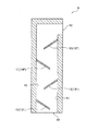
吸着部10は、たとえば、ガス排出流路9のガス取込口91とガス排出口92との間に配置されている。吸着部10は、たとえば、ガス排出流路9の内部に突出する吸着フィン10Fによって構成されている。吸着フィン10Fは、たとえば、ガス排出流路9の内壁面からガス排出流路9の内側に向けて突出させた平板状の部材であり、ガス排出流路9の一部を遮るように設けられている。
The
図1に示す例において、ガス排出流路9のガス取込口91とガス排出口92との間に複数の吸着フィン10Fが設けられている。なお、吸着フィン10Fは、一つであってもよいが、より多くのヒュームを吸着させる観点から、ガス排出流路9は、複数の吸着フィン10Fを有していることが好ましい。吸着フィン10Fは、たとえば、ガス排出流路9の延在方向に沿って、ガス排出流路9の対向する内壁面から交互に突出させて設けられ、ガス排出流路9を流れるガスを蛇行させるように設けられている。
In the example shown in FIG. 1, a plurality of
吸着フィン10Fは、たとえば、水平方向に対して傾斜して設けられ、先端部が基端部よりも鉛直方向の下方に位置している。吸着フィン10Fの基端部は、ガス排出流路9の内壁面に接続され、吸着フィン10Fの先端部は、ガス排出流路9の内壁面から離隔している。吸着フィン10Fは、たとえば、適宜の駆動部によって、ガス排出流路9の内壁面からガス排出流路9の内部に突出した状態と、ガス排出流路9の内壁面に沿って配置された状態との間で、可動に設けられていてもよい。これにより、最初にチャンバー2の内部から空気を排出するときに、吸着フィン10Fをガス排出流路9の内壁面に沿って寝かせて、ガス排出流路9の圧力損失または流路抵抗を低下させることができる。
For example, the
ガス排出流路9は、たとえば、真空ポンプ3の吸引口3aの断面積以上の断面積を有している。ここで、ガス排出流路9の断面積とは、たとえば、ガス排出流路9の任意の断面における最小の流路面積を意味する。たとえば、吸着フィン10Fがガス排出流路9の内壁面から突出した状態では、吸着フィン10Fの先端とガス排出流路9の内壁面との間に形成される開口の面積が、ガス排出流路9の任意の断面における最小の流路面積であり、ガス排出流路9の断面積となる。
The gas discharge channel 9 has, for example, a cross-sectional area greater than or equal to the cross-sectional area of the
なお、ガス排出流路9のガス排出口92がチャンバー2のガス出口2bを介して真空ポンプ3の吸引口3aに接続されている場合には、チャンバー2のガス出口2bは、真空ポンプ3の吸引口3aの断面積以上の断面積であることが好ましい。また、ガス排出流路9のガス排出口92の断面積すなわち開口面積は、真空ポンプ3の吸引口3aまたはチャンバー2のガス出口2bの断面積すなわち開口面積以上であることが好ましい。
When the
加熱部11,12は、吸着部10を加熱するための構成である。本実施形態の付加製造装置は、吸着フィン10Fに内蔵された内部ヒータ11a(図2および図3を参照。)によって構成された加熱部11と、ガス排出流路9を外部から加熱する外部ヒータ12aによって構成された加熱部12とを備えている。なお、加熱部11,12は、いずれか一方を省略することも可能である。
The
図2は、図1に示す吸着フィン10Fの模式的な断面図である。図3は、図2に示す吸着フィン10Fの模式的な平面図である。加熱部11は、たとえば、吸着フィン10Fに内蔵された内部ヒータ11aと、この内部ヒータ11aに電力を供給する電源部11bと、によって構成されている。
FIG. 2 is a schematic cross-sectional view of the
内部ヒータ11aは、たとえばニッケルクロム線や鉄クロム線などの電熱線や、セラミックヒータによって構成することができる。セラミックヒータは、たとえば、アルミナや窒化ケイ素などのセラミックスに発熱体が内蔵された構成を有し、セラミックスと発熱体とが同時に焼結されて一体化されることで、外部環境に対する優れた密閉性と絶縁性を有している。
The
図2および図3に示す例において、吸着フィン10Fは、たとえば一端に開口を有する中空の板状に構成されている。内部ヒータ11aであるセラミックヒータは、吸着フィン10Fの一端の開口から吸着フィン10Fの内部に挿入されている。吸着フィン10Fは、たとえば、アルミニウムやステンレス鋼などの金属材料からなり、内部ヒータ11aであるセラミックヒータを覆うように内部ヒータ11aの外側に取り付けられ、内部ヒータ11aから取り外し可能に構成されている。
In the example shown in FIGS. 2 and 3, the
図1に示すように、加熱部12は、ガス排出流路9を外部から加熱する外部ヒータ12aによって構成されている。外部ヒータ12aは、たとえば、ハロゲンランプによって構成することができる。外部ヒータ12aは、ガス排出流路9を外部から加熱することで、ガス排出流路9に設けられた吸着部10を加熱する。なお、外部ヒータ12aは、ハロゲンランプに限定されず、たとえば高周波誘導加熱によってガス排出流路9を外部から加熱してもよい。
As shown in FIG. 1, the
付加製造装置1が加熱部12として外部ヒータ12aを備える場合には、外部ヒータ12aによって加熱されるガス排出流路9の内壁面を、材料粉末Pの溶融時に発生するヒュームを吸着させる吸着部10とすることができる。また、この場合、ガス排出流路9は、吸着フィン10Fを加熱する内部ヒータ11aを有しなくてもよいし、吸着フィン10Fを有しなくてもよい。また、加熱部12は、たとえば、付加製造部5のステージ51に載置された材料粉末Pを予熱する予熱ヒータ12bを有してもよい。予熱ヒータ12bは、たとえば、ハロゲンランプによって構成することができる。
When the additional manufacturing apparatus 1 includes the
また、図示を省略するが、ガス排出流路9の内部に配置したフィルタを吸着部10としてもよい。この場合、吸着部10としてのフィルタは、加熱部11を構成する内部ヒータ11aまたは加熱部12を構成する外部ヒータ12aによって加熱することができる。なお、吸着部10としてのフィルタの開口面積は、真空ポンプ3の吸引口3aまたはチャンバー2のガス出口2bの断面積すなわち開口面積以上であることが好ましい。
Although not shown, a filter disposed inside the gas discharge channel 9 may be used as the
以下、本実施形態の付加製造装置1の作用について説明する。 Hereinafter, the operation of the additive manufacturing apparatus 1 of the present embodiment will be described.
本実施形態の付加製造装置1によって造形物Mの付加製造を行うには、まず、真空ポンプ3によってチャンバー2の内部の空気を排出し、チャンバー2の内部を大気圧よりも減圧して真空状態にする。また、チャンバー2のガス入口2aからアルゴンガスや窒素ガスなどの不活性ガスを導入するとともに、真空ポンプ3によってチャンバー2の内部のガスを排出し、チャンバー2の内部を大気圧よりも低い真空状態に維持する。
In order to perform the additional manufacturing of the shaped article M by the additional manufacturing apparatus 1 of the present embodiment, first, the air inside the
次に、付加製造部5のステージ51を側壁の上端部の開口部から所定のピッチで下降させ、付加製造部5に所定量の付加製造用の材料粉末Pを収容可能な状態にする。次に、材料供給部4のステージ41を所定のピッチで上昇させ、開口部よりも上方に所定量の付加製造用の材料粉末Pを押し上げる。次に、材料供給部4の開口部を横断するようにリコータ7を移動させ、材料供給部4の開口部の上方に押し上げられた材料粉末Pをリコータ7によって付加製造部5に移動させる。
Next, the
さらに、付加製造部5の開口部を横断するようにリコータ7を移動させ、リコータ7によって材料粉末Pを付加製造部5の開口部へ導入して付加製造部5のステージ51に載置するとともに、リコータ7によって材料粉末Pを付加製造部5の開口部の高さに平坦に均して敷き詰める。このとき、余分な材料粉末Pは、リコータ7によって回収部6の開口部へ導入され、回収部6に収容されて回収される。その後、リコータ7を逆方向に移動させて元の位置に戻す。
Further, the
次に、付加製造部5のステージ51上に敷き詰められた材料粉末Pを、たとえば、加熱部12の予熱ヒータ12bによって予熱する。次に、造形物Mの三次元形状のデータに基づいて、ビーム源8から、付加製造部5のステージ51上の予熱された材料粉末Pの所定の領域に、レーザや電子ビームなどの高エネルギービームBを照射する。これにより、所定の領域の材料粉末Pが溶融結合されて造形物Mの一部が形成される。このとき、材料粉末Pの溶融にともなって、たとえば金属蒸気を含むヒュームが発生する。
Next, the material powder P spread on the
本実施形態の付加製造装置1は、前述のように、粉末床溶融結合方式を採用し、チャンバー2に収容された材料粉末Pに高エネルギービームBを照射して材料粉末Pを溶融結合させる。ここで、本実施形態の付加製造装置1は、前述のように、チャンバー2からガスを排出するガス排出流路9と、このガス排出流路9に設けられて材料粉末Pの溶融時に発生するヒュームを吸着させる吸着部10と、この吸着部10を加熱する加熱部11,12と、を備えている。
As described above, the additive manufacturing apparatus 1 of the present embodiment employs the powder bed fusion bonding method, and irradiates the material powder P accommodated in the
この構成により、ガス排出流路9を介してチャンバー2からガスを排出するときに、ガス排出流路9にヒュームを含むガスが取り込まれると、ガス排出流路9に設けられた吸着部10によってガスに含まれるヒュームが吸着される。より詳細には、吸着部10は、ヒュームの吸着時に、加熱部11,12によってヒュームの吸着に適した温度に加熱され、ガスに含まれるヒュームを効果的に吸着することができる。
With this configuration, when gas containing fumes is taken into the gas discharge channel 9 when the gas is discharged from the
これにより、ガス排出流路9を通過したガスからヒュームを効果的に除去することができ、真空ポンプ3によるヒュームの吸い込みを抑制し、真空ポンプ3の不具合を回避することができる。なお、材料粉末Pが金属粉末である場合、加熱部11,12によって加熱された吸着部10のヒュームの吸着に適した温度は、たとえば、約150℃以上、約450℃以下の温度である。
As a result, fumes can be effectively removed from the gas that has passed through the gas discharge flow path 9, suction of fumes by the vacuum pump 3 can be suppressed, and problems with the vacuum pump 3 can be avoided. In addition, when the material powder P is a metal powder, the temperature suitable for the adsorption | suction of the fume of the adsorption |
また、本実施形態の付加製造装置1において、ガス排出流路9は、チャンバー2の内部に開口したガス取込口91と、真空ポンプ3に接続されるガス排出口92とを有している。そして、吸着部10は、ガス取込口91とガス排出口92との間に配置されている。この構成により、ガス排出流路9のガス取込口91から取り込まれたガスに含まれるヒュームは、ガスがガス取込口91からガス排出口92へ到達するまでの間に、吸着部10によって吸着されて除去される。したがって、真空ポンプ3に接続されるガス排出流路9のガス排出口92において、ガスに含まれるヒュームが可及的に除去された状態になり、真空ポンプ3によるヒュームの吸い込みを抑制し、真空ポンプ3の不具合を回避することができる。
Further, in the additive manufacturing apparatus 1 of the present embodiment, the gas discharge flow path 9 has a
また、本実施形態の付加製造装置1において、ガス排出流路9は、チャンバー2の内部に設けられ、ガス排出口92は、チャンバー2に設けられたガス出口2bを介して真空ポンプ3に接続されている。これにより、ガス排出流路9を大気圧よりも減圧されたチャンバー2内に設置することができ、ガス排出流路9をチャンバー2の外部に設置する場合と比較して、構成を簡潔にすることができる。また、ガス排出流路9に設けられた吸着部10を、外部環境よりも高温のチャンバー2の内部で加熱することができ、吸着部10の加熱が容易になる。さらに、ガス排出流路9のガス取込口91をチャンバー2の内部の最適な位置に配置することが容易になる。
In addition manufacturing apparatus 1 of this embodiment, gas discharge channel 9 is provided in
また、本実施形態の付加製造装置1において、ガス排出流路9は、鉛直方向に延びて、下端部にガス取込口91を有するとともに、上端部にガス排出口92を有している。この構成により、ガス排出流路9のガス取込口91を鉛直方向の低い位置に開口させることができ、高温で上方に移動しやすいヒュームがガス取込口91に取り込まれるのを抑制することができる。したがって、吸着部10に吸着されるヒュームを減少させてメンテナンス頻度を低下させることができるだけでなく、真空ポンプ3によるヒュームの吸い込みを抑制し、真空ポンプ3の不具合を回避することができる。さらに、鉛直方向に延びるガス排出流路9の吸着部10に吸着されたヒュームに由来する堆積物が剥離して落下しても、その落下した堆積物を、ガス排出流路9の下端部のガス取込口91から排出することができる。
Moreover, in the additional manufacturing apparatus 1 of this embodiment, the gas discharge flow path 9 extends in the vertical direction, has a
また、本実施形態の付加製造装置1において、吸着部10は、ガス排出流路9の内部に突出する吸着フィン10Fによって構成されている。この構成により、吸着フィン10Fによってヒュームを吸着させる吸着部10の表面積を増加させ、より多くのヒュームを吸着部10に吸着させることが可能になる。さらに、ガス排出流路9の内部に突出する吸着フィン10Fによって、ガス排出流路9の内部のガスを蛇行させることで、たとえばガスに含まれるヒューム中の微粒子を吸着フィン10Fに衝突または接触させ、吸着部10により多くのヒュームを吸着させることが可能になる。
Further, in the additive manufacturing apparatus 1 of the present embodiment, the
また、本実施形態の付加製造装置1において、吸着フィン10Fは、水平方向に対して傾斜して設けられ、先端部が基端部よりも鉛直方向の下方に位置している。この構成により、吸着フィン10Fに吸着されたヒュームに由来する堆積物が剥離したときに、剥離した堆積物は、重力の作用によって吸着フィン10Fの基端部から先端部へと移動して下方へ落下し、ガス排出流路9の下端部のガス取込口91から排出される。これにより、吸着フィン10Fに堆積物が堆積するのを抑制することができる。また、ガス排出流路9の断面積が減少するのを抑制しつつ、吸着フィン10Fの表面積を増加させることができる。さらに、鉛直方向上方へ流れるガスに乱流を生じさせ、ガスに含まれるヒュームをより効果的に吸着フィン10Fに吸着することができる。
In addition manufacturing apparatus 1 of this embodiment,
また、本実施形態の付加製造装置1において、加熱部11は、吸着フィン10Fに内蔵された内部ヒータ11aによって構成されている。これにより、吸着フィン10Fを効率よく加熱して、吸着フィン10Fの温度をヒュームの吸着に適した温度に維持することができる。また、吸着フィン10Fから内部ヒータ11aを取り外し可能に構成することで、吸着フィン10Fの交換時に内部ヒータ11aを再利用することができ、維持費用を抑制することができる。
In addition manufacturing apparatus 1 of this embodiment,
また、本実施形態の付加製造装置1において、加熱部12は、ガス排出流路9を外部から加熱する外部ヒータ12aによって構成されている。この構成により、外部ヒータ12aによってガス排出流路9を外部から加熱することで吸着部10を加熱し、吸着部10の温度をヒュームの吸着に適した温度に維持することができる。また、外部ヒータ12aによってガス排出流路9の内壁面をヒュームの吸着に適した温度に加熱することで、ガス排出流路9の内壁面が吸着部10となる。これにより、ガス排出流路9を流れるガスに含まれるヒュームを、ガス排出流路9の内壁面の吸着部10によって吸着して除去することができる。したがって、真空ポンプ3によるヒュームの吸い込みを抑制し、真空ポンプ3の不具合を回避することができる。
Moreover, in the additional manufacturing apparatus 1 of this embodiment, the
また、本実施形態の付加製造装置1において、ガス排出流路9は、真空ポンプ3の吸引口3aの断面積以上の断面積を有している。これにより、ガス排出流路9による圧力損失が低減され、真空ポンプ3の負荷を低減することができる。
In addition manufacturing apparatus 1 of this embodiment, gas discharge channel 9 has a cross-sectional area more than the cross-sectional area of
以上説明したように、本実施形態によれば、真空ポンプ3によるヒュームの吸い込みを抑制し、真空ポンプ3の不具合を回避することが可能な付加製造装置1を提供することができる。なお、本開示の付加製造装置は、前述の実施形態に係る付加製造装置1の構成に限定されない。以下、前述の実施形態に係る付加製造装置1の変形例について説明する。 As described above, according to the present embodiment, it is possible to provide the additional manufacturing apparatus 1 capable of suppressing the suction of fumes by the vacuum pump 3 and avoiding the malfunction of the vacuum pump 3. In addition, the additional manufacturing apparatus of this indication is not limited to the structure of the additional manufacturing apparatus 1 which concerns on above-mentioned embodiment. Hereinafter, modifications of the additive manufacturing apparatus 1 according to the above-described embodiment will be described.
図4は、図1の付加製造装置1のガス排出流路9の変形例を示す断面図である。この変形例において、付加製造装置1は、外部ヒータ12aを有しない。すなわち、加熱部11は、吸着フィン10Fに内蔵された内部ヒータ11aおよび電源部11bによって構成されている。また、この変形例において、ガス排出流路9は、ガス取込口91と、吸着部10である吸着フィン10Fとの間に、ヒュームを冷却する冷却部13を有している。冷却部13は、たとえば、ヒュームの吸着に適した温度よりも低い、たとえば150℃未満の温度に維持されている。
FIG. 4 is a cross-sectional view showing a modification of the gas discharge passage 9 of the additive manufacturing apparatus 1 of FIG. In this modification, the additive manufacturing apparatus 1 does not have the
冷却部13は、たとえば、ガス排出流路9の内部に突出する冷却フィン13Fによって構成することができる。また、冷却フィン13Fは、たとえば、水平方向に対して傾斜して設けられ、先端部が基端部よりも鉛直方向の下方に位置している。なお、ガス取込口91と、吸着部10である吸着フィン10Fとの間のガス排出流路9の内壁面を冷却部13とすることも可能である。冷却部13は、冷媒を流す冷媒流路を内部に有してもよい。
The cooling
このように、本変形例に係る付加製造装置1において、ガス排出流路9は、ガス取込口91と吸着部10との間に、ヒュームを冷却する冷却部13を有している。この構成により、冷却部13に接したヒュームは冷却され、ヒュームに含まれる溶融した金属の微粒子が凝固して落下し、ガス排出流路9のガス取込口91から排出される。これにより、吸着部10に到達するヒュームを減少させ、吸着部10に吸着されるヒュームを減少させてメンテナンス頻度を低下させることができる。また、真空ポンプ3によるヒュームの吸い込みをより効果的に抑制し、真空ポンプ3の不具合を回避することができる。
As described above, in the additive manufacturing apparatus 1 according to this modification, the gas discharge channel 9 includes the cooling
また、本変形例に係る付加製造装置1において、冷却部13は、ガス排出流路9の内部に突出する冷却フィン13Fによって構成されている。この構成により、冷却部13の表面積を増加させ、冷却部13の放熱を促進させ、冷却部13の温度を、たとえば、ヒュームの吸着に適した温度よりも低い150℃未満の温度に維持することが容易になる。また、ガス排出流路9を流れるガスに含まれるヒュームをより効果的に冷却して、ヒュームに含まれる溶融した金属の微粒子をより多く凝固させてガス排出流路9のガス取込口91から排出することができる。
Further, in the additive manufacturing apparatus 1 according to this modification, the cooling
また、本変形例に係る付加製造装置1において、冷却フィン13Fは、水平方向に対して傾斜して設けられ、先端部が基端部よりも鉛直方向の下方に位置している。この構成により、冷却フィン13Fによって冷却して凝固させたヒュームに含まれる金属の微粒子を、重力の作用によって冷却フィン13Fの基端部から先端部へ移動させて落下させることができる。これにより、金属の微粒子が冷却フィン13Fの上に堆積することが防止される。
Moreover, in the additional manufacturing apparatus 1 which concerns on this modification, the cooling
図5は、図1の付加製造装置1のガス排出流路9の変形例を示す断面図である。この変形例において、吸着フィン10Fは、水平方向に対して傾斜して設けられているが、先端部が基端部よりも鉛直方向の下方に位置した吸着フィン10Fと、基端部が先端部よりも鉛直方向の下方に位置した吸着フィン10Fとが交互に配置されている。このような構成によっても、前述の実施形態に係る付加製造装置1と同様の効果を奏することができる。
FIG. 5 is a cross-sectional view showing a modification of the gas discharge passage 9 of the additive manufacturing apparatus 1 of FIG. In this modification, the
以上、図面を用いて本発明の実施の形態を詳述してきたが、具体的な構成はこの実施形態に限定されるものではなく、本発明の要旨を逸脱しない範囲における設計変更等があっても、それらは本発明に含まれるものである。 The embodiment of the present invention has been described in detail with reference to the drawings, but the specific configuration is not limited to this embodiment, and there are design changes and the like without departing from the gist of the present invention. They are also included in the present invention.
1 付加製造装置
2 チャンバー
2b ガス出口
3 真空ポンプ
3a 吸引口
9 ガス排出流路
91 ガス取込口
92 ガス排出口
10 吸着部
10F 吸着フィン
11 加熱部
11a 内部ヒータ
12 加熱部
12a 外部ヒータ
13 冷却部
13F 冷却フィン
B 高エネルギービーム
P 材料粉末
DESCRIPTION OF SYMBOLS 1
Claims (12)
前記チャンバーからガスを排出するガス排出流路と、
前記ガス排出流路に設けられて前記材料粉末の溶融時に発生するヒュームを吸着させる吸着部と、
前記吸着部を加熱する加熱部と、を備えることを特徴とする付加製造装置。 An additive manufacturing apparatus of a powder bed fusion bonding method in which a material powder accommodated in a chamber is irradiated with a high energy beam to melt bond the material powder,
A gas discharge passage for discharging gas from the chamber;
An adsorbing portion that is provided in the gas discharge channel and adsorbs fumes generated when the material powder is melted;
An addition manufacturing apparatus comprising: a heating unit that heats the adsorption unit.
前記吸着部は、前記ガス取込口と前記ガス排出口との間に配置されていることを特徴とする請求項1に記載の付加製造装置。 The gas discharge flow path has a gas intake port that is opened inside the chamber, and a gas discharge port that is connected to a vacuum pump.
The additive manufacturing apparatus according to claim 1, wherein the adsorption unit is disposed between the gas intake port and the gas discharge port.
前記ガス排出口は、前記チャンバーに設けられたガス出口を介して前記真空ポンプに接続されることを特徴とする請求項2に記載の付加製造装置。 The gas discharge channel is provided inside the chamber,
The additive manufacturing apparatus according to claim 2, wherein the gas discharge port is connected to the vacuum pump via a gas outlet provided in the chamber.
Priority Applications (2)
| Application Number | Priority Date | Filing Date | Title |
|---|---|---|---|
| JP2018025909A JP2019142019A (en) | 2018-02-16 | 2018-02-16 | Additive manufacturing apparatus |
| PCT/JP2019/002277 WO2019159634A1 (en) | 2018-02-16 | 2019-01-24 | Additive manufacturing apparatus |
Applications Claiming Priority (1)
| Application Number | Priority Date | Filing Date | Title |
|---|---|---|---|
| JP2018025909A JP2019142019A (en) | 2018-02-16 | 2018-02-16 | Additive manufacturing apparatus |
Publications (1)
| Publication Number | Publication Date |
|---|---|
| JP2019142019A true JP2019142019A (en) | 2019-08-29 |
Family
ID=67618671
Family Applications (1)
| Application Number | Title | Priority Date | Filing Date |
|---|---|---|---|
| JP2018025909A Pending JP2019142019A (en) | 2018-02-16 | 2018-02-16 | Additive manufacturing apparatus |
Country Status (2)
| Country | Link |
|---|---|
| JP (1) | JP2019142019A (en) |
| WO (1) | WO2019159634A1 (en) |
Cited By (1)
| Publication number | Priority date | Publication date | Assignee | Title |
|---|---|---|---|---|
| JP7457674B2 (en) | 2021-08-13 | 2024-03-28 | 日本電子株式会社 | 3D additive manufacturing equipment |
Families Citing this family (1)
| Publication number | Priority date | Publication date | Assignee | Title |
|---|---|---|---|---|
| CN110435149B (en) * | 2019-08-28 | 2020-06-26 | 南京涵铭置智能科技有限公司 | 3D printer and purification control system with purification performance |
Family Cites Families (9)
| Publication number | Priority date | Publication date | Assignee | Title |
|---|---|---|---|---|
| JPS60114570A (en) * | 1983-11-25 | 1985-06-21 | Canon Inc | Evacuating system for plasma cvd device |
| JP2000070664A (en) * | 1998-06-18 | 2000-03-07 | Kokusai Electric Co Ltd | Heating type trap apparatus and film forming apparatus |
| JP2000256856A (en) * | 1999-03-11 | 2000-09-19 | Tokyo Electron Ltd | Treating device, vacuum exhaust system for treating device, vacuum cvd device, vacuum exhaust system for vacuum cvd device and trapping device |
| GB0816310D0 (en) * | 2008-09-05 | 2008-10-15 | Mtt Technologies Ltd | Filter assembly |
| US20150298394A1 (en) * | 2012-11-05 | 2015-10-22 | Yehoshua Sheinman | System and method for direct inkjet printing of 3d objects |
| CN107257729A (en) * | 2014-12-23 | 2017-10-17 | 瑞尼斯豪公司 | Increasing material manufacturing apparatus and method |
| JP6325475B2 (en) * | 2015-03-18 | 2018-05-16 | 株式会社東芝 | Gas recycling apparatus, additive manufacturing apparatus, and additive manufacturing method |
| JP6812123B2 (en) * | 2016-03-30 | 2021-01-13 | キヤノン株式会社 | 3D modeling equipment |
| JP6095147B1 (en) * | 2016-07-13 | 2017-03-15 | 株式会社ソディック | Additive manufacturing equipment |
-
2018
- 2018-02-16 JP JP2018025909A patent/JP2019142019A/en active Pending
-
2019
- 2019-01-24 WO PCT/JP2019/002277 patent/WO2019159634A1/en active Application Filing
Cited By (1)
| Publication number | Priority date | Publication date | Assignee | Title |
|---|---|---|---|---|
| JP7457674B2 (en) | 2021-08-13 | 2024-03-28 | 日本電子株式会社 | 3D additive manufacturing equipment |
Also Published As
| Publication number | Publication date |
|---|---|
| WO2019159634A1 (en) | 2019-08-22 |
Similar Documents
| Publication | Publication Date | Title |
|---|---|---|
| JP2020518720A (en) | Powder bed fusion apparatus and method | |
| JP6216881B2 (en) | Laminated production of single crystal alloy parts | |
| WO2019159634A1 (en) | Additive manufacturing apparatus | |
| EP3147047B1 (en) | Apparatus for producing a three-dimensional workpiece with improved gas flow and manufacturing method of a three-dimensional workpiece | |
| JP6466681B2 (en) | Manufacturing method and manufacturing apparatus for large three-dimensional workpiece | |
| RU2481191C2 (en) | Device for generative creation of 3d object with isolated area of construction | |
| WO2018196868A1 (en) | Three-dimensional printing method | |
| CN102812175B (en) | The cutting-off method of carbon fiber base material | |
| TW201540843A (en) | A device for heating a mold | |
| CN104646670A (en) | High-frequency induction melting type metal 3D (three-dimensional) printing machine | |
| WO2019159635A1 (en) | Additive manufacturing device | |
| EP3281726B1 (en) | Apparatus for producing a three-dimensional workpiece with temperature-controlled shielding gas | |
| TWI794654B (en) | Lamination molding apparatus | |
| JP2007180457A (en) | Soldering method, method of manufacturing semiconductor module, and soldering apparatus | |
| CN109501248A (en) | A kind of preheating cylinder body and its manufacturing process for the sintering of high-temperature laser constituency | |
| US20170087669A1 (en) | Apparatus and method for producing and/or repairing in particular rotationally symmetrical components | |
| JP6573510B2 (en) | Porous material manufacturing method and manufacturing apparatus | |
| JP2015101739A (en) | Apparatus for manufacturing laminated structure of molten layers, method for manufacturing laminated structure of molten layers, and laminated structure of molten layers | |
| US20200222982A1 (en) | Apparatus for Additive Manufacturing | |
| JP2017165998A (en) | Three-dimensional molding method | |
| CN112512735A (en) | Powder bed melting apparatus and method | |
| US10478911B2 (en) | Method of joining metals and non-metals with foil and products so joined | |
| WO2022078630A1 (en) | Method of manufacturing a build plate for use in an additive manufacturing process | |
| TW201800338A (en) | Process for melting and purification of metals, in particular scrap metals | |
| CN115279573A (en) | Method and apparatus for producing 3D shaped articles using high performance radiation emitters |