EP4134004A1 - Regelung eines analytsensors mit zwei elektroden - Google Patents
Regelung eines analytsensors mit zwei elektroden Download PDFInfo
- Publication number
- EP4134004A1 EP4134004A1 EP21190800.9A EP21190800A EP4134004A1 EP 4134004 A1 EP4134004 A1 EP 4134004A1 EP 21190800 A EP21190800 A EP 21190800A EP 4134004 A1 EP4134004 A1 EP 4134004A1
- Authority
- EP
- European Patent Office
- Prior art keywords
- electrode
- analyte
- analyte sensor
- electric potential
- sensor
- Prior art date
- Legal status (The legal status is an assumption and is not a legal conclusion. Google has not performed a legal analysis and makes no representation as to the accuracy of the status listed.)
- Pending
Links
- 239000012491 analyte Substances 0.000 title claims abstract description 211
- 230000033228 biological regulation Effects 0.000 title description 6
- 238000000034 method Methods 0.000 claims abstract description 30
- 230000004044 response Effects 0.000 claims abstract description 15
- WQZGKKKJIJFFOK-GASJEMHNSA-N Glucose Natural products OC[C@H]1OC(O)[C@H](O)[C@@H](O)[C@@H]1O WQZGKKKJIJFFOK-GASJEMHNSA-N 0.000 claims description 26
- 239000008103 glucose Substances 0.000 claims description 26
- QVGXLLKOCUKJST-UHFFFAOYSA-N atomic oxygen Chemical compound [O] QVGXLLKOCUKJST-UHFFFAOYSA-N 0.000 claims description 24
- 239000001301 oxygen Substances 0.000 claims description 24
- 229910052760 oxygen Inorganic materials 0.000 claims description 24
- 238000003487 electrochemical reaction Methods 0.000 claims description 19
- 108090000790 Enzymes Proteins 0.000 claims description 13
- 102000004190 Enzymes Human genes 0.000 claims description 13
- 238000006243 chemical reaction Methods 0.000 claims description 13
- 229940088598 enzyme Drugs 0.000 claims description 13
- BASFCYQUMIYNBI-UHFFFAOYSA-N platinum Chemical compound [Pt] BASFCYQUMIYNBI-UHFFFAOYSA-N 0.000 claims description 7
- 230000001105 regulatory effect Effects 0.000 claims description 7
- 108010015776 Glucose oxidase Proteins 0.000 claims description 6
- 239000004366 Glucose oxidase Substances 0.000 claims description 5
- 229940116332 glucose oxidase Drugs 0.000 claims description 5
- 235000019420 glucose oxidase Nutrition 0.000 claims description 5
- 229910052723 transition metal Inorganic materials 0.000 claims description 5
- 239000000758 substrate Substances 0.000 claims description 4
- 150000003624 transition metals Chemical class 0.000 claims description 4
- 125000002791 glucosyl group Chemical group C1([C@H](O)[C@@H](O)[C@H](O)[C@H](O1)CO)* 0.000 claims description 3
- 229910052697 platinum Inorganic materials 0.000 claims description 3
- KGIGUEBEKRSTEW-UHFFFAOYSA-N 2-vinylpyridine Chemical class C=CC1=CC=CC=N1 KGIGUEBEKRSTEW-UHFFFAOYSA-N 0.000 claims description 2
- WAJNQUGXOWDSHH-UHFFFAOYSA-N cyclopenta-1,3-diene;2-cyclopenta-2,4-dien-1-ylethanamine;iron(2+) Chemical compound [Fe+2].C=1C=C[CH-]C=1.NCC[C-]1C=CC=C1 WAJNQUGXOWDSHH-UHFFFAOYSA-N 0.000 claims description 2
- PCHJSUWPFVWCPO-UHFFFAOYSA-N gold Chemical compound [Au] PCHJSUWPFVWCPO-UHFFFAOYSA-N 0.000 claims description 2
- 229910052737 gold Inorganic materials 0.000 claims description 2
- 239000010931 gold Substances 0.000 claims description 2
- 230000007704 transition Effects 0.000 claims 1
- 239000000463 material Substances 0.000 description 13
- 238000005259 measurement Methods 0.000 description 13
- 238000007254 oxidation reaction Methods 0.000 description 10
- 239000011540 sensing material Substances 0.000 description 9
- 238000013461 design Methods 0.000 description 8
- 230000003647 oxidation Effects 0.000 description 6
- 238000010586 diagram Methods 0.000 description 5
- MHAJPDPJQMAIIY-UHFFFAOYSA-N Hydrogen peroxide Chemical compound OO MHAJPDPJQMAIIY-UHFFFAOYSA-N 0.000 description 4
- 239000008280 blood Substances 0.000 description 4
- 210000004369 blood Anatomy 0.000 description 4
- 230000008859 change Effects 0.000 description 4
- 230000008569 process Effects 0.000 description 4
- 229920006395 saturated elastomer Polymers 0.000 description 4
- 230000002596 correlated effect Effects 0.000 description 3
- 210000003722 extracellular fluid Anatomy 0.000 description 3
- 238000004519 manufacturing process Methods 0.000 description 3
- 229910052751 metal Inorganic materials 0.000 description 3
- 239000002184 metal Substances 0.000 description 3
- 238000012545 processing Methods 0.000 description 3
- 239000000243 solution Substances 0.000 description 3
- 108030001056 (S)-2-hydroxy-acid oxidases Proteins 0.000 description 2
- 102100038838 2-Hydroxyacid oxidase 2 Human genes 0.000 description 2
- 108010025188 Alcohol oxidase Proteins 0.000 description 2
- 108010089254 Cholesterol oxidase Proteins 0.000 description 2
- 239000004971 Cross linker Substances 0.000 description 2
- 108010015133 Galactose oxidase Proteins 0.000 description 2
- 108030000910 L-aspartate oxidases Proteins 0.000 description 2
- 108010069325 L-glutamate oxidase Proteins 0.000 description 2
- 229910021607 Silver chloride Inorganic materials 0.000 description 2
- HVYWMOMLDIMFJA-DPAQBDIFSA-N cholesterol Chemical compound C1C=C2C[C@@H](O)CC[C@]2(C)[C@@H]2[C@@H]1[C@@H]1CC[C@H]([C@H](C)CCCC(C)C)[C@@]1(C)CC2 HVYWMOMLDIMFJA-DPAQBDIFSA-N 0.000 description 2
- 239000004020 conductor Substances 0.000 description 2
- 238000011161 development Methods 0.000 description 2
- 230000018109 developmental process Effects 0.000 description 2
- 206010012601 diabetes mellitus Diseases 0.000 description 2
- 238000003306 harvesting Methods 0.000 description 2
- 108010018734 hexose oxidase Proteins 0.000 description 2
- 238000012544 monitoring process Methods 0.000 description 2
- 229920000642 polymer Polymers 0.000 description 2
- 238000005070 sampling Methods 0.000 description 2
- 229910052709 silver Inorganic materials 0.000 description 2
- 239000004332 silver Substances 0.000 description 2
- HKZLPVFGJNLROG-UHFFFAOYSA-M silver monochloride Chemical compound [Cl-].[Ag+] HKZLPVFGJNLROG-UHFFFAOYSA-M 0.000 description 2
- 239000000126 substance Substances 0.000 description 2
- 230000009466 transformation Effects 0.000 description 2
- ZTOJFFHGPLIVKC-YAFCTCPESA-N (2e)-3-ethyl-2-[(z)-(3-ethyl-6-sulfo-1,3-benzothiazol-2-ylidene)hydrazinylidene]-1,3-benzothiazole-6-sulfonic acid Chemical compound S\1C2=CC(S(O)(=O)=O)=CC=C2N(CC)C/1=N/N=C1/SC2=CC(S(O)(=O)=O)=CC=C2N1CC ZTOJFFHGPLIVKC-YAFCTCPESA-N 0.000 description 1
- 108010050375 Glucose 1-Dehydrogenase Proteins 0.000 description 1
- JVTAAEKCZFNVCJ-UHFFFAOYSA-M Lactate Chemical compound CC(O)C([O-])=O JVTAAEKCZFNVCJ-UHFFFAOYSA-M 0.000 description 1
- 230000009286 beneficial effect Effects 0.000 description 1
- WQZGKKKJIJFFOK-VFUOTHLCSA-N beta-D-glucose Chemical compound OC[C@H]1O[C@@H](O)[C@H](O)[C@@H](O)[C@@H]1O WQZGKKKJIJFFOK-VFUOTHLCSA-N 0.000 description 1
- 239000000560 biocompatible material Substances 0.000 description 1
- 210000001124 body fluid Anatomy 0.000 description 1
- 239000010839 body fluid Substances 0.000 description 1
- 239000003990 capacitor Substances 0.000 description 1
- 235000012000 cholesterol Nutrition 0.000 description 1
- 230000000875 corresponding effect Effects 0.000 description 1
- 238000004132 cross linking Methods 0.000 description 1
- 230000000593 degrading effect Effects 0.000 description 1
- 239000003814 drug Substances 0.000 description 1
- 230000000694 effects Effects 0.000 description 1
- 239000007772 electrode material Substances 0.000 description 1
- 239000008151 electrolyte solution Substances 0.000 description 1
- KTWOOEGAPBSYNW-UHFFFAOYSA-N ferrocene Chemical compound [Fe+2].C=1C=C[CH-]C=1.C=1C=C[CH-]C=1 KTWOOEGAPBSYNW-UHFFFAOYSA-N 0.000 description 1
- -1 for example Substances 0.000 description 1
- 238000009499 grossing Methods 0.000 description 1
- 238000001727 in vivo Methods 0.000 description 1
- 230000002427 irreversible effect Effects 0.000 description 1
- 150000002576 ketones Chemical class 0.000 description 1
- 230000007246 mechanism Effects 0.000 description 1
- 239000000203 mixture Substances 0.000 description 1
- 238000012986 modification Methods 0.000 description 1
- 230000004048 modification Effects 0.000 description 1
- 230000001590 oxidative effect Effects 0.000 description 1
- 239000002245 particle Substances 0.000 description 1
- 230000010363 phase shift Effects 0.000 description 1
- 230000010287 polarization Effects 0.000 description 1
- 229920002401 polyacrylamide Polymers 0.000 description 1
- 230000027756 respiratory electron transport chain Effects 0.000 description 1
- 238000001228 spectrum Methods 0.000 description 1
- 238000003860 storage Methods 0.000 description 1
- 230000001225 therapeutic effect Effects 0.000 description 1
- 230000001052 transient effect Effects 0.000 description 1
- 150000003626 triacylglycerols Chemical class 0.000 description 1
Images
Classifications
-
- G—PHYSICS
- G01—MEASURING; TESTING
- G01N—INVESTIGATING OR ANALYSING MATERIALS BY DETERMINING THEIR CHEMICAL OR PHYSICAL PROPERTIES
- G01N27/00—Investigating or analysing materials by the use of electric, electrochemical, or magnetic means
- G01N27/26—Investigating or analysing materials by the use of electric, electrochemical, or magnetic means by investigating electrochemical variables; by using electrolysis or electrophoresis
- G01N27/403—Cells and electrode assemblies
- G01N27/4035—Combination of a single ion-sensing electrode and a single reference electrode
-
- A—HUMAN NECESSITIES
- A61—MEDICAL OR VETERINARY SCIENCE; HYGIENE
- A61B—DIAGNOSIS; SURGERY; IDENTIFICATION
- A61B5/00—Measuring for diagnostic purposes; Identification of persons
- A61B5/145—Measuring characteristics of blood in vivo, e.g. gas concentration, pH value; Measuring characteristics of body fluids or tissues, e.g. interstitial fluid, cerebral tissue
- A61B5/14532—Measuring characteristics of blood in vivo, e.g. gas concentration, pH value; Measuring characteristics of body fluids or tissues, e.g. interstitial fluid, cerebral tissue for measuring glucose, e.g. by tissue impedance measurement
-
- A—HUMAN NECESSITIES
- A61—MEDICAL OR VETERINARY SCIENCE; HYGIENE
- A61B—DIAGNOSIS; SURGERY; IDENTIFICATION
- A61B5/00—Measuring for diagnostic purposes; Identification of persons
- A61B5/145—Measuring characteristics of blood in vivo, e.g. gas concentration, pH value; Measuring characteristics of body fluids or tissues, e.g. interstitial fluid, cerebral tissue
- A61B5/1468—Measuring characteristics of blood in vivo, e.g. gas concentration, pH value; Measuring characteristics of body fluids or tissues, e.g. interstitial fluid, cerebral tissue using chemical or electrochemical methods, e.g. by polarographic means
- A61B5/1477—Measuring characteristics of blood in vivo, e.g. gas concentration, pH value; Measuring characteristics of body fluids or tissues, e.g. interstitial fluid, cerebral tissue using chemical or electrochemical methods, e.g. by polarographic means non-invasive
-
- A—HUMAN NECESSITIES
- A61—MEDICAL OR VETERINARY SCIENCE; HYGIENE
- A61B—DIAGNOSIS; SURGERY; IDENTIFICATION
- A61B5/00—Measuring for diagnostic purposes; Identification of persons
- A61B5/145—Measuring characteristics of blood in vivo, e.g. gas concentration, pH value; Measuring characteristics of body fluids or tissues, e.g. interstitial fluid, cerebral tissue
- A61B5/1486—Measuring characteristics of blood in vivo, e.g. gas concentration, pH value; Measuring characteristics of body fluids or tissues, e.g. interstitial fluid, cerebral tissue using enzyme electrodes, e.g. with immobilised oxidase
-
- A—HUMAN NECESSITIES
- A61—MEDICAL OR VETERINARY SCIENCE; HYGIENE
- A61B—DIAGNOSIS; SURGERY; IDENTIFICATION
- A61B5/00—Measuring for diagnostic purposes; Identification of persons
- A61B5/145—Measuring characteristics of blood in vivo, e.g. gas concentration, pH value; Measuring characteristics of body fluids or tissues, e.g. interstitial fluid, cerebral tissue
- A61B5/14507—Measuring characteristics of blood in vivo, e.g. gas concentration, pH value; Measuring characteristics of body fluids or tissues, e.g. interstitial fluid, cerebral tissue specially adapted for measuring characteristics of body fluids other than blood
-
- A—HUMAN NECESSITIES
- A61—MEDICAL OR VETERINARY SCIENCE; HYGIENE
- A61B—DIAGNOSIS; SURGERY; IDENTIFICATION
- A61B5/00—Measuring for diagnostic purposes; Identification of persons
- A61B5/145—Measuring characteristics of blood in vivo, e.g. gas concentration, pH value; Measuring characteristics of body fluids or tissues, e.g. interstitial fluid, cerebral tissue
- A61B5/14542—Measuring characteristics of blood in vivo, e.g. gas concentration, pH value; Measuring characteristics of body fluids or tissues, e.g. interstitial fluid, cerebral tissue for measuring blood gases
-
- G—PHYSICS
- G01—MEASURING; TESTING
- G01N—INVESTIGATING OR ANALYSING MATERIALS BY DETERMINING THEIR CHEMICAL OR PHYSICAL PROPERTIES
- G01N27/00—Investigating or analysing materials by the use of electric, electrochemical, or magnetic means
- G01N27/26—Investigating or analysing materials by the use of electric, electrochemical, or magnetic means by investigating electrochemical variables; by using electrolysis or electrophoresis
- G01N27/28—Electrolytic cell components
- G01N27/30—Electrodes, e.g. test electrodes; Half-cells
- G01N27/327—Biochemical electrodes, e.g. electrical or mechanical details for in vitro measurements
- G01N27/3271—Amperometric enzyme electrodes for analytes in body fluids, e.g. glucose in blood
-
- G—PHYSICS
- G01—MEASURING; TESTING
- G01N—INVESTIGATING OR ANALYSING MATERIALS BY DETERMINING THEIR CHEMICAL OR PHYSICAL PROPERTIES
- G01N27/00—Investigating or analysing materials by the use of electric, electrochemical, or magnetic means
- G01N27/26—Investigating or analysing materials by the use of electric, electrochemical, or magnetic means by investigating electrochemical variables; by using electrolysis or electrophoresis
- G01N27/403—Cells and electrode assemblies
- G01N27/413—Concentration cells using liquid electrolytes measuring currents or voltages in voltaic cells
Definitions
- the invention relates to an electro-chemical analyte sensor and to a method of operating an electrochemical analyte sensor for measuring an analyte concentration.
- Electrochemical analyte sensors exploit the fact that certain electrochemical reactions of an analyte to be detected or to be measured can generate electrical signals, e.g. electric currents or electric potentials, that can correlate with the concentration of the analyte to be detected, e.g. that are directly or indirectly proportional to the concentration of the analyte.
- electrical signals e.g. electric currents or electric potentials
- a potentiometric electrochemical analyte sensor can generate electric potentials that can exhibit a logarithmic dependence on the concentration of an analyte to be detected.
- an amperometric electrochemical analyte sensor can generate an electric current that can flow between electrodes of the sensor that can be proportional to the concentration of the analyte to be measured.
- Such analyte sensors are, for example, commonly used for measuring glucose levels, and in particular can be part of in-vivo continuous glucose monitoring systems that measure glucose levels in the blood and/or in interstitial fluids of patients suffering from diabetes.
- the reference point for measurements of current analyte sensors e.g. a reference electric potential
- a reference electric potential can shift or drift over time in unexpected ways, thereby significantly degrading the accuracy, robustness and reliability of analyte measurements.
- a method for measuring an analyte concentration using an electrochemical analyte sensor may comprise an analyte sensor comprising a first electrode and a second electrode, wherein the first electrode can be configured to electrochemically react with the/an analyte for generating an electrical signal, e.g. a current signal, and wherein the method may comprise one, some or all of the following exemplary steps:
- the determined electric potential working point can also be understood as electric reference potential point that can serve as a reference for the analyte concentration measurements of the analyte sensor.
- the step of determining an electric potential working point of the analyte sensor based on the determined current signal may be understood as setting or identifying or reaching or obtaining or regulating an electric potential working point based on the determined current signal.
- the step of determining an electric potential working point of the analyte sensor based on the determined current signal may comprise or be understood as setting or identifying or reaching or obtaining or regulating an electric potential working point range based on the determined current signal or as selecting or setting an electric potential working point from an electric potential working point range that has been set or identified or obtained from the determined current signal.
- an analyte sensor operating at an electric potential working point or at/within an electric potential working point range that has been obtained or set or determined using a modulated voltage signal applied between the first electrode and the second electrode works stably, without sensor drift or unexpected changes in a/the reference potential.
- Said electric potential working point or electric potential working point range determined by the application of a modulated voltage signal between the first electrode and the second electrode can inter alia ensure that the electrical signal, e.g. a current signal, generated at the first electrode from the electrochemical reaction between the first electrode and the analyte to be measured is positively correlated to the concentration of the analyte to be measured, e.g. is directly proportional to the concentration of the analyte, wherein the proportional factor is constant and does not change over time.
- the electrical signal e.g. a current signal
- the herein described means and method step also allow dispensing with the need for a dedicated reference electrode, in particular reference electrodes that are prone to undesired material wear and that can leak undesired material into their environments, such as, for example, Ag/AgCI (silver / silver chloride) reference electrodes. This can inter alia improve the lifetime of an analyte sensor.
- a dedicated reference electrode in particular reference electrodes that are prone to undesired material wear and that can leak undesired material into their environments, such as, for example, Ag/AgCI (silver / silver chloride) reference electrodes. This can inter alia improve the lifetime of an analyte sensor.
- Ag/AgCI silver / silver chloride
- The/said modulated voltage signal that can be applied between the first electrode and the second electrode can be applied in time-discrete steps.
- time-discrete step can inter alia also be understood as a time interval.
- a modulation of the voltage signal can be applied.
- an exemplary modulated voltage signal V ( t ) that can be applied by a controller between a/the first electrode and a/the second electrode of an exemplary analyte sensor may be exemplary defined by the following equation.
- V t V cont t + V ⁇ sin 2 ⁇ ft
- t is a/the time parameter, wherein t can be a continuous (analog) or a discrete (digital) time parameter, e.g. in case of t being a discrete (digital) time parameter t can, for example, be represented by a time step or time interval t k , with index k being a natural number, V cont ( t ) is an exemplary voltage applied / outputted by a controller at time t or at step or time interval t k , V ⁇ is an exemplary voltage amplitude also set/controlled by a/the controller, sin() is the sinus function, and ⁇ is a frequency, i.e. a modulation frequency.
- the controller can be analog or digital, e.g. can be a micro controller or another digital control device.
- a/the to be applied (analog) modulated voltage signal V(t) may be generated from digital controller voltage outputs by means of a digital-to-analog converter (DAC) or by means of using pulse-width-modulation (PWM) in combination with an analog low pass filter.
- DAC digital-to-analog converter
- PWM pulse-width-modulation
- the calculated sum can be passed to a digital-to-analog converter (DAC) or to a component applying a pulse-width-modulation (PWM) with a low pass filter to generate an/the (analog) modulated voltage signal V(t) to be applied between a/the first electrode and a/the second electrode of an exemplary analyte sensor.
- DAC digital-to-analog converter
- PWM pulse-width-modulation
- the above-identified modulated voltage signal is exemplary only and other modulations are conceivable too.
- the voltage signal is modulated not at every time step, but only at predetermined time steps or that the voltage signal is modulated continuously or quasi-continuously.
- an exemplary modulated voltage signal V(t) to be applied between a/the first electrode and a/the second electrode of an exemplary analyte sensor may itself also be generated using pulse-width-modulation (PWM).
- PWM pulse-width-modulation
- An exemplary sampling time or time interval, t k can be in the order of 0.01/ ⁇ , e.g.1/16 Hz to 1 Hz.
- Such an exemplary sampling time or time interval provides a sufficient signal resolution, while also being energy efficient and allowing an optimized power consumption of the analyte sensor.
- An exemplary frequency ⁇ may lie around a few cycles per minute, e.g. 1/min - 10/min, but can also be higher.
- said exemplary frequency ⁇ may also be set such as to avoid possible interference with frequency ranges from other resonators that might be present in the environment of the analyte sensor.
- the exemplary voltage amplitude V ⁇ can lie in the order of a few mV, e.g. 1 to 10 mV, preferably lower than 25 mV.
- a modulated current signal I ( t ) can be generated.
- a/the current signal I ( t ) of the analyte sensor in response to the applied modulated voltage signal and/or in response to the electrical signal generated at the first electrode from the reaction with the analyte can be determined / measured.
- the measuring and/or processing of the current signal can be carried out in an analog and/or digital manner.
- ADC analog-digital-converter
- ADC analog-digital-converter
- the amplitude Î of said generated current signal for example, can be measured / determined as follows.
- a Discrete Fourier Transformation (DTF) with an implementation of a Fast Fourier Transformation (FFT) can be applied.
- DTF Discrete Fourier Transformation
- FFT Fast Fourier Transformation
- a lock-in-amplifier can be used for processing an/the analog current signal and the modulation signal to isolate the signal component (e.g. Î sin (2 ⁇ t k + ⁇ ⁇ ) with ⁇ ⁇ being a phase shift) and to return a voltage that is proportional to Î as output.
- the signal component e.g. Î sin (2 ⁇ t k + ⁇ ⁇ ) with ⁇ ⁇ being a phase shift
- the task can be simplified to measuring the signal power or maximum amplitude of the output of a narrow band pass filter centered on the modulation frequency.
- the average current signal ⁇ I ( t ) ⁇ can be measured / determined.
- a smoothing filter e.g. a moving average filter
- a low pass filter can be used.
- the step of determining the electric potential working point (or electric potential working point range) of the analyte sensor based on the determined current signal I ( t ), wherein said current signal has been generated in response to the applied modulated voltage signal V(t) can exemplary comprise the following regulation step:
- the level of the applied modulated voltage signal V ( t ) can be regulated such that the following condition is fulfilled.
- the regulation of the applied modulated voltage signal V ( t ) can, for example, inter alia be carried out using a proportional-integral controller, e.g. a proportional-integral controller with log I ⁇ ⁇ I t ⁇ as input.
- a proportional-integral controller e.g. a proportional-integral controller with log I ⁇ ⁇ I t ⁇ as input.
- the maximum threshold ,max threshold may be equal or close to 0.05 and the minimum threshold, min threshold , may be equal or close to 0.01.
- a/the controller for regulating the applied modulated voltage signal V ( t ), i.e. a/the proportional-integral controller can be set / configured such that the condition according to equation 3 is fulfilled.
- a/the proportional-integral controller can be set / configured such that I ⁇ ⁇ I t ⁇ is set to a fixed value, e.g. 0.01 or 0.02.
- a digital proportional integral controller with a digitally computed input log I ⁇ ⁇ I t ⁇ may be used.
- an analog proportional integral controller, with an analog input log I ⁇ ⁇ I t ⁇ can be used as well, wherein the analog proportional integral controller can inter alia comprise various operation amplifier circuits.
- a negative reference value e.g. log(0.01) or other value
- log(0.01) or other value can be selected / set as a reference value for the controller. This can inter alia reduce signal noise and improve control loop stability.
- an electric potential working point E wp for the analyte sensor i.e. for the first electrode / working electrode / anode, can be reached / set / identified / obtained that lies close to a (local) saturation point or saturation region of the current-potential relation of the analyte sensor.
- the expression close to a (local) saturation point or saturation region may refer to the case of the electric potential of the first electrode / working electrode / anode being within a desired or predetermined percentage range, e.g. within 20% or within 10% or less, with respect to an electric potential of the first electrode / working electrode / anode in the saturation region / saturation plateau of the current-potential relation of the analyte sensor.
- V L can inter alia be understood as an average or mean of the applied modulated voltage signal V ( t ) , and wherein, for example, when the applied modulated voltage signal is a mean-free signal, e.g. a sine signal, the controller output voltage V cont can converge to V L , after possible transient signals of the controlled system have decayed.
- V cont can be considered an estimator for V L .
- the electric potential at the first electrode / working electrode / anode is driven towards the desired electric potential working point E wp .
- applying a modulated voltage signal between the first electrode / working electrode / anode and the second electrode / cathode of the analyte sensor and determining a current signal in response to the applied modulated voltage signal can allow to implicitly determine / set / reach / identify / obtain the desired electric potential working point E wp of the analyte sensor.
- V L E A + E C , wherein E C is the electric potential of/at the second electrode of the analyte sensor, wherein the index C exemplary denotes the second electrode as cathode, E A is the electric potential of/at the second electrode / working electrode of the analyte sensor, wherein the index A exemplary denotes the second electrode as anode.
- the electric potential E C of the second electrode / cathode may inter alia be known or determined from factory calibrations or from calibrations during use / operation of the analyte sensor.
- Said electric potential working point E wp can then serve as reference potential for the analyte sensor.
- a regulation step of the applied modulated voltage signal as exemplary described above converges / moves towards an/the electric potential working point E wp in a reliable manner.
- an oxygen saturation / oxygen saturation level / oxygen concentration in the environment of the second electrode can be determined and outputted, e.g. outputted to a display.
- the oxygen contained in body fluids as cathode reaction.
- the oxygen activity (which is closely correlated with its concentration) can be related to the cathode potential by the Nernst equation and in case of large current densities, extensions analogue to Butler-Volmer equation apply.
- the change in cathode potential can be used to deduce the oxygen levels at the surface. Considering an oxygen transport model this can then enable the estimation of oxygen levels in the vicinity of the analyte sensor.
- the information that can be derived from the measurement of an oxygen saturation / oxygen saturation level / oxygen concentration in the environment of the second electrode can inter alia be used to compensate for possible measurement errors in the analyte concentration to be measured.
- energy that is released by the electrochemical reaction of the analyte with the first electrode can be harvested for supplying energy to the operation of the analyte sensor, e.g. can be supplied to an electric circuitry / electronics / battery / power source / processor of the analyte sensor.
- the analyte reaction with the corresponding electron acceptor reaction has overall a negative free reaction enthalpy (i.e. occurs voluntarily), a part of this energy can be harvested.
- the electrode current resulting from glucose oxidization can be accumulated in a capacitor and by means of a direct-current-to-direct-current (DCDC) conversion, the stored energy can be periodically transferred to an electrical consumer or storage unit.
- DCDC direct-current-to-direct-current
- the possible optional energy harvesting mechanism can also be used as means to realize the voltage signal modulation
- An exemplary analyte to be measured by the analyte sensor can be glucose, i.e. the herein described method steps can be used to measure a/the concentration of glucose and the measured analyte concentration, e.g. the measured glucose concentration, can be outputted, for example on a display.
- the analyte may be selected from the group consisting of glucose, cholesterol, ketones, triglycerides, and lactate. Additionally or alternatively, however, other types of analytes and/or any combination of analytes may be determined.
- the analyte is glucose.
- glucose may be understood as relating to glucose measured by a herein described analyte sensor according to the herein described method steps in the interstitial fluid of a patient and/or to glucose measured in the blood of a patient, i.e. blood glucose.
- An exemplary analyte sensor for measuring an analyte concentration can comprise a first electrode and a second electrode, wherein the first electrode can be configured to electrochemically react with the analyte to be measured for generating an electrical signal.
- the analyte sensor can be configured for measuring an analyte concentration according to one, some or all of the above and herein exemplary method steps.
- an/the exemplary analyte sensor may comprise no more than two electrodes, in particular no more than two separate electrodes.
- an/the exemplary analyte sensor may comprise exactly two electrodes, i.e. exactly two separate electrodes.
- a single electrode of an/the exemplary analyte sensor may have separate parts / components and may also be implemented as a combined electrode.
- the/said first electrode of said exemplary analyte sensor can be a/the working electrode, e.g. can act as anode during the electrochemical reaction with the analyte.
- the second electrode can be an electrode selected from a group comprising the following types: a counter electrode and a combined counter/reference electrode.
- reference electrodes that are prone to undesired material wear and that can leak undesired material into their environments, such as, for example, Ag/AgCI (silver / silver chloride) reference electrode can be avoided in the herein described analyte sensor design.
- Ag/AgCI silver / silver chloride
- the second electrode material may inter alia comprise a biocompatible material, such as, for example, gold or platinum.
- the two-electrodes-only design of the herein described analyte sensor further allows a more cost-effective manufacturing and a more compact design of the analyte sensor.
- the first electrode of an exemplary analyte sensor may comprise at least one enzyme.
- the first electrode may comprise only one enzyme or a mixture of two or more enzymes. Only one enzyme is preferred. Specifically, the enzyme is capable of catalyzing a chemical reaction converting the analyte, in particular glucose.
- the at least one enzyme is selected from the group consisting of a glucose oxidase (EC 1.1.3.4), a hexose oxidase (EC 1.1.3.5), an (S)-2 hydroxy acid oxidase (EC 1.1.3.15), a cholesterol oxidase (EC 1.1.3.6), a glucose dehydrogenase, a galactose oxidase (EC 1.1.3.9), an alcohol oxidase (EC 1.1.3.13), an L-glutamate oxidase (EC 1.4.3.11), and an L-aspartate oxidase (EC 1.4.3.16).
- the at least one enzyme is a glucose oxidase (GOx) and/or modifications thereof.
- the at least one enzyme may be comprised in a sensing material.
- sensing material specifically may refer, without limitation, to a material that may be or may comprise at least a polymeric material; specifically it may be or may comprise at least a polymeric material and at least a metal containing complex.
- the metal containing complex may be selected from the group consisting of transition metal element complexes, specifically the metal containing complex may be selected from osmium-complexes, ruthenium-complexes, vanadium-complexes, cobalt-complexes, and iron-complexes, such as ferrocenes, such as 2-aminoethylferrocene.
- the sensing material may be a polymeric transition metal complex as described for example in WO 01/36660 A2 , the content of which is included by reference.
- the sensing material may comprise a modified poly(vinylpyridine) backbone loaded with poly(bi-imidizyl) Os complexes covalently coupled through a bidentate linkage.
- a suitable sensing material is further described in Feldmann et al, Diabetes Technology & Therapeutics, 5 (5), 2003, 769-779 , the content of which is included by reference.
- Suitable sensing materials further may include ferrocene-containing polyacrylamide-based viologen-modified redox polymer, pyrrole-2,2'-azino-bis(3-ethylbenzthiazoline-6-sulfonic acid)(ABTS)-pyrene, Naphthoquinone-LPEI.
- the polymeric transition metal complex may represent a redox mediator incorporated into a cross-linked redox polymer network. This is advantageous as it may facilitate electron transfer between the at least one enzyme or analyte and the conductive trace. In order to avoid a sensor drift, the redox mediator and the enzyme may be covalently incorporated into a polymeric structure.
- the sensing material may comprise a polymeric material and MnO2-particles or any other material catalyzing hydrogen peroxide oxidation reaction as well as the at least one enzyme.
- Another material catalyzing hydrogen peroxide oxidation reaction is Pt (platinum).
- the sensing material may additionally comprise at least one crosslinker; the crosslinker may for example be capable of crosslinking at least part of the sensing material.
- the second electrode can further be configured to measure an oxygen saturation / oxygen saturation level / oxygen saturation concentration in its environment.
- Such an optional measurement of an oxygen saturation / oxygen saturation level / oxygen saturation concentration can be used to compensate for possible measurement errors of the analyte sensor, since the oxygen saturation / oxygen saturation level / oxygen saturation concentration can influence the electrochemical reaction used by the analyte sensor to measure the analyte concentration, in particular in the case of oxidative electrochemical reactions.
- the optional possibility to measure and output an oxygen saturation / oxygen saturation level / oxygen saturation concentration in the blood and/or in interstitial fluids of patients may also be useful for further additional therapeutic and diagnostic purposes.
- the first and second electrode can be arranged on opposing sides of a/the substrate of the analyte sensor.
- This exemplary design enables a more compact analyte sensor and more cost efficient manufacturing, since it is not necessary to have the conductive traces for both electrodes on the same side. For example, it is possible to cover a/the first side of a/the substrate with the conductive material of the first electrode / working electrode and a/the second side of a/the substrate with the conductive material of the second electrode / counter electrode and then apply further layers of materials such Ag/AgCI if necessary.
- non-planar designs such as cylindrical designs, wherein a first electrode may be a rod electrode and the second electrode may be a cylindrical electrode that forms a sleeve around the second electrode, or wherein both electrodes are cylindrical with different diameters such that one cylindrical electrode can form a sleeve around the other.
- An/the herein exemplary described analyte sensor may be implemented in a system for measuring an analyte concentration.
- an/the herein exemplary described analyte sensor may be part of a system comprising an implantable medical device, e.g. a continuous glucose monitoring system comprising an implantable medical device with a herein described analyte sensor.
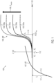
- Fig.1 exemplary shows a diagram 100 illustrating the characteristic curve(s) or characteristic line(s) 103, 104, 105, 106, 107 for the relationship of current (or current density), I (ordinate axis, 102), and electric potential (abscissa axis, 101), E , of/in an exemplary analyte sensor for the anodic and cathodic partial reaction(s) of the electrochemical conversion, e.g. via oxidation, of the analyte to be detected, e.g. glucose, with/at an enzyme, e.g. glucose oxidase, of the first electrode, i.e. the working electrode, of an exemplary analyte sensor.
- an enzyme e.g. glucose oxidase
- curves or lines 103, 104, 105, and 106 show the behavior 108 of the relationship(s) of current (or current density) and electric potential at the first electrode, i.e. the working electrode, WE, or anode, of exemplary analyte sensor for different amounts or concentrations of the analyte to be detected, e.g. glucose.
- Said curves or lines 103, 104, 105, and 106 inter alia illustrate that the exemplary oxidation reaction at the first electrode, i.e. the working electrode, saturates for sufficiently large electric potentials, as illustrated by the plateau regions 103a, 104a, 105a and 106a of said curves.
- the electrochemical conversion process / electrochemical reaction comes to a standstill, i.e. the electrochemical conversion process / electrochemical reaction, e.g. oxidation, can be irreversible.
- Curve 114 illustrates exemplary the behavior 107 for the relationship of current (or current density) and electric potential at the second electrode, e.g. a/the counter electrode, CE, or cathode, of the exemplary analyte sensor.
- the behavior 107 for the relationship of current (or current density) and electric potential at the second electrode is essentially not affected or only affected by a negligible amount of the analyte concentration, i.e. the shape of the curve 114 is essentially not affected by the analyte concentration.
- the amount or absolute value of the current at the first electrode is equal to the amount or absolute value of current at the second electrode.
- an electric potential working point E wp , 113, of the analyte sensor based on the determined current signal can be determined, wherein said determined electric potential working point E wp , lies in a border region / border range of the electric potential of the analyte sensor / a border region / border range of the electric potential of the first electrode of the analyte sensor that is located just before a saturation plateau, 103a, 104a, 105a or 106a, e.g. just at or before the kink of curves 103, 104, 105, 106.
- applying a/the modulated voltage signal V ( t ) between the first electrode / working electrode / anode and the second electrode / cathode of the analyte sensor and determining a current signal in response to the applied modulated voltage signal can allow to implicitly determine / set / reach / identify / obtain the desired electric potential working point E wp , 113, of the analyte sensor.
- the electric potential at the first electrode / working electrode / anode is driven towards the desired electric potential working point E wp , 113.
- a possible condition to be fulfilled may be that the ratio of the determined amplitude of the current signal at the first electrode to the determined average current signal falls within a predetermined range, e.g. set by exemplary threshold values as indicated by equation 3, thereby determining / setting / reaching / obtaining / identifying an/the electric potential working point E wp , 113, of the first electrode, that is close to the saturation region of the potential, i.e. just before a saturation plateau 103a, 104a, 105a or 106a, e.g. just at or before the kink of curves 103, 104, 105, 106.
- the regulation of the applied modulated voltage signal can for example be carried out by using an analog or digital proportional-integral controller, e.g. a proportional-integral controller with log I ⁇ ⁇ I t ⁇ as input.
- an analog or digital proportional-integral controller e.g. a proportional-integral controller with log I ⁇ ⁇ I t ⁇ as input.
- the thus determined / set / identified / obtained / reached electric potential working point E wp , 113, of the analyte sensor / of the first electrode / of the working electrode / of the anode can then be used as reference electric potential for operating the analyte sensor.
- the electric potential E A at the first electrode / anode / working electrode corresponds to the electric potential working point E wp that has been reached by applying a/the modulated voltage signal or voltage level V L .
- the thus determined electric potential working point E wp , 113, of the analyte sensor can ensure that the electrical signal, i.e. the current signal, generated by the first electrode from the electrochemical reaction with the analyte is positively correlated to the concentration of the analyte to be measured, e.g. is directly proportional to the concentration of the analyte to be measured, e.g. glucose, and that, for example, this proportional relationship maintains a constant proportionality factor and is not affected by changes or drifts in electric potential of the analyte sensor during measurement operations of the analyte sensor.
- the electrical signal i.e. the current signal
- the thus determined electric potential working point E wp , 113, of the analyte sensor / of the working electrode of the analyte sensor can provide a more precise correlation of the electrical signal, e.g. the current signal, generated by the electrochemical reaction with respect to the concentration / concentration level(s) of an analyte to be measured.
- the electrical signal e.g. the current signal
- concentration / concentration level(s) of an analyte to be measured can be obtained.
- the arrow marked with the reference sign 109 exemplary indicates increasing values for the concentration of an analyte, C analyte , to be measured, e.g. glucose.
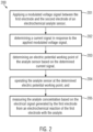
- Fig. 2 shows an exemplary flow diagram for an exemplary method 200 for measuring an analyte concentration using an electrochemical analyte sensor, wherein the analyte sensor is comprising a first electrode and a second electrode, and the first electrode is being configured to react with the analyte for generating an electrical signal.
- a modulated voltage signal between the first electrode and the second electrode can be applied 201 and in response to the applied modulated voltage signal a current signal can be determined 202.
- An electric potential working point of the analyte sensor can then be determined 203 based on the determined current signal.
- the analyte sensor / the first electrode of the analyte sensor can then be operated 204 at the determined electric potential working point and the concentration of an analyte to be measured, e.g. glucose, can then be measured 205 based on / in dependence of the electrical signal, e.g. a current signal generated by the analyte sensor from the electrochemical reaction(s) of the analyte with the analyte sensor, i.e. with the electrodes of the analyte sensor.
- an analyte to be measured e.g. glucose
- Exemplary characteristic curve diagram 101 Exemplary electric potential, exemplary abscissa axis 102 Exemplary electric current or current density, exemplary ordinate axis 103 Exemplary characteristic curve or line for relationship of electric current or current density to electric potential at first electrode / working electrode / anode at an exemplary first concentration level of analyte 103a Exemplary plateau of curve 103 marking an exemplary region / range where the electrochemical reaction, e.g.
- an oxidation, of the analyte with the analyte sensor is saturated 104
- an oxidation, of the analyte with the analyte sensor is saturated 106
- Exemplary plateau of curve 106 marking an exemplary region / range where the electrochemical reaction, e.g. an oxidation, of the analyte with the analyte sensor is saturated Exemplary behavior of second electrode / counter electrode, CE, / cathode 108
- Exemplary behavior of first electrode / working electrode, WE, / anode 109 Exemplary direction marking an increase of concentration / concentration levels of an analyte to be measured, e.g.
- glucose 110 Exemplary current / current density / current signal at first electrode / working electrode, WE, / anode 111
- Exemplary current / current density / current signal at second electrode / counter electrode, WE, / cathode 112 Exemplary applied voltage V(t) or voltage level V L 113
- Exemplary electric potential working point E wp 114 Exemplary characteristic curve or line for relationship of electric current or current density to electric potential at the second electrode / counter electrode, CE, / cathode 200
Priority Applications (8)
| Application Number | Priority Date | Filing Date | Title |
|---|---|---|---|
| EP21190800.9A EP4134004A1 (de) | 2021-08-11 | 2021-08-11 | Regelung eines analytsensors mit zwei elektroden |
| KR1020247004620A KR20240040752A (ko) | 2021-08-11 | 2022-08-09 | 2-전극 분석물 센서의 조절 |
| AU2022326187A AU2022326187A1 (en) | 2021-08-11 | 2022-08-09 | Regulation of a two-electrode analyte sensor |
| PCT/EP2022/072303 WO2023017015A1 (en) | 2021-08-11 | 2022-08-09 | Regulation of a two-electrode analyte sensor |
| CA3226386A CA3226386A1 (en) | 2021-08-11 | 2022-08-09 | Regulation of a two-electrode analyte sensor |
| CN202280056048.7A CN117813049A (zh) | 2021-08-11 | 2022-08-09 | 双电极分析物传感器的调节 |
| IL310173A IL310173A (en) | 2021-08-11 | 2022-08-09 | Two-electrode test substance sensor regulation |
| TW111129984A TW202317033A (zh) | 2021-08-11 | 2022-08-10 | 雙電極分析物感測器之調節 |
Applications Claiming Priority (1)
| Application Number | Priority Date | Filing Date | Title |
|---|---|---|---|
| EP21190800.9A EP4134004A1 (de) | 2021-08-11 | 2021-08-11 | Regelung eines analytsensors mit zwei elektroden |
Publications (1)
| Publication Number | Publication Date |
|---|---|
| EP4134004A1 true EP4134004A1 (de) | 2023-02-15 |
Family
ID=77300830
Family Applications (1)
| Application Number | Title | Priority Date | Filing Date |
|---|---|---|---|
| EP21190800.9A Pending EP4134004A1 (de) | 2021-08-11 | 2021-08-11 | Regelung eines analytsensors mit zwei elektroden |
Country Status (8)
| Country | Link |
|---|---|
| EP (1) | EP4134004A1 (de) |
| KR (1) | KR20240040752A (de) |
| CN (1) | CN117813049A (de) |
| AU (1) | AU2022326187A1 (de) |
| CA (1) | CA3226386A1 (de) |
| IL (1) | IL310173A (de) |
| TW (1) | TW202317033A (de) |
| WO (1) | WO2023017015A1 (de) |
Citations (4)
| Publication number | Priority date | Publication date | Assignee | Title |
|---|---|---|---|---|
| US4798655A (en) * | 1987-03-19 | 1989-01-17 | Howard Diamond | Multiparameter analytical electrode structure and method of measurement |
| WO2001036660A2 (en) | 1999-11-15 | 2001-05-25 | Therasense, Inc. | Transition metal complexes attached to a polymer via a flexible chain |
| US20100147707A1 (en) * | 2008-12-17 | 2010-06-17 | General Electric Company | Anionically-charged polymer detection method |
| US20100213057A1 (en) * | 2009-02-26 | 2010-08-26 | Benjamin Feldman | Self-Powered Analyte Sensor |
-
2021
- 2021-08-11 EP EP21190800.9A patent/EP4134004A1/de active Pending
-
2022
- 2022-08-09 CN CN202280056048.7A patent/CN117813049A/zh active Pending
- 2022-08-09 AU AU2022326187A patent/AU2022326187A1/en active Pending
- 2022-08-09 CA CA3226386A patent/CA3226386A1/en active Pending
- 2022-08-09 WO PCT/EP2022/072303 patent/WO2023017015A1/en active Application Filing
- 2022-08-09 IL IL310173A patent/IL310173A/en unknown
- 2022-08-09 KR KR1020247004620A patent/KR20240040752A/ko unknown
- 2022-08-10 TW TW111129984A patent/TW202317033A/zh unknown
Patent Citations (4)
| Publication number | Priority date | Publication date | Assignee | Title |
|---|---|---|---|---|
| US4798655A (en) * | 1987-03-19 | 1989-01-17 | Howard Diamond | Multiparameter analytical electrode structure and method of measurement |
| WO2001036660A2 (en) | 1999-11-15 | 2001-05-25 | Therasense, Inc. | Transition metal complexes attached to a polymer via a flexible chain |
| US20100147707A1 (en) * | 2008-12-17 | 2010-06-17 | General Electric Company | Anionically-charged polymer detection method |
| US20100213057A1 (en) * | 2009-02-26 | 2010-08-26 | Benjamin Feldman | Self-Powered Analyte Sensor |
Non-Patent Citations (1)
| Title |
|---|
| FELDMANN ET AL., DIABETES TECHNOLOGY & THERAPEUTICS, vol. 5, no. 5, 2003, pages 769 - 779 |
Also Published As
| Publication number | Publication date |
|---|---|
| AU2022326187A1 (en) | 2024-01-18 |
| IL310173A (en) | 2024-03-01 |
| WO2023017015A1 (en) | 2023-02-16 |
| KR20240040752A (ko) | 2024-03-28 |
| CA3226386A1 (en) | 2023-02-16 |
| CN117813049A (zh) | 2024-04-02 |
| TW202317033A (zh) | 2023-05-01 |
Similar Documents
| Publication | Publication Date | Title |
|---|---|---|
| US11701037B2 (en) | Method and electronics unit for detecting in-vivo properties of a biosensor | |
| US20070299617A1 (en) | Biofouling self-compensating biosensor | |
| US7081195B2 (en) | Systems and methods for improving electrochemical analyte sensors | |
| US9228978B2 (en) | Identifying ionizable species with voltammetric duty cycles | |
| RU2372588C2 (ru) | Способ и устройство для реализации основанных на пороговой величине функций корректировки для биосенсоров | |
| KR101979257B1 (ko) | CGMS 센서용 AgCl 보충시스템 및 보충방법 | |
| EP4134004A1 (de) | Regelung eines analytsensors mit zwei elektroden | |
| US20220296131A1 (en) | Miniaturized analyte sensor | |
| Dam et al. | Highly sensitive glucose sensor based on work function changes measured by an E MOSFET | |
| EP3851040A1 (de) | Körperüberwachungsvorrichtung und zugehöriges verfahren | |
| US20230051071A1 (en) | Analyte sensor and a method for producing an analyte sensor | |
| TW202217299A (zh) | 判定分析物感測器的至少一種薄膜性質的方法 | |
| Kalidas et al. | Biosensors | |
| CN116209392A (zh) | 提取用于分析物浓度确定的参数 | |
| Murase et al. | Biosensor |
Legal Events
| Date | Code | Title | Description |
|---|---|---|---|
| PUAI | Public reference made under article 153(3) epc to a published international application that has entered the european phase |
Free format text: ORIGINAL CODE: 0009012 |
|
| STAA | Information on the status of an ep patent application or granted ep patent |
Free format text: STATUS: THE APPLICATION HAS BEEN PUBLISHED |
|
| AK | Designated contracting states |
Kind code of ref document: A1 Designated state(s): AL AT BE BG CH CY CZ DE DK EE ES FI FR GB GR HR HU IE IS IT LI LT LU LV MC MK MT NL NO PL PT RO RS SE SI SK SM TR |
|
| STAA | Information on the status of an ep patent application or granted ep patent |
Free format text: STATUS: REQUEST FOR EXAMINATION WAS MADE |
|
| 17P | Request for examination filed |
Effective date: 20230728 |
|
| RBV | Designated contracting states (corrected) |
Designated state(s): AL AT BE BG CH CY CZ DE DK EE ES FI FR GB GR HR HU IE IS IT LI LT LU LV MC MK MT NL NO PL PT RO RS SE SI SK SM TR |
|
| REG | Reference to a national code |
Ref country code: HK Ref legal event code: DE Ref document number: 40087253 Country of ref document: HK |