EP4133482B1 - Sprachverbesserung mit reduzierter bandbreite und bandbreitenerweiterung - Google Patents
Sprachverbesserung mit reduzierter bandbreite und bandbreitenerweiterung Download PDFInfo
- Publication number
- EP4133482B1 EP4133482B1 EP21722025.0A EP21722025A EP4133482B1 EP 4133482 B1 EP4133482 B1 EP 4133482B1 EP 21722025 A EP21722025 A EP 21722025A EP 4133482 B1 EP4133482 B1 EP 4133482B1
- Authority
- EP
- European Patent Office
- Prior art keywords
- frequency
- signal
- speech
- ear
- cutoff
- Prior art date
- Legal status (The legal status is an assumption and is not a legal conclusion. Google has not performed a legal analysis and makes no representation as to the accuracy of the status listed.)
- Active
Links
Images

Classifications
-
- G—PHYSICS
- G10—MUSICAL INSTRUMENTS; ACOUSTICS
- G10L—SPEECH ANALYSIS TECHNIQUES OR SPEECH SYNTHESIS; SPEECH RECOGNITION; SPEECH OR VOICE PROCESSING TECHNIQUES; SPEECH OR AUDIO CODING OR DECODING
- G10L21/00—Speech or voice signal processing techniques to produce another audible or non-audible signal, e.g. visual or tactile, in order to modify its quality or its intelligibility
- G10L21/02—Speech enhancement, e.g. noise reduction or echo cancellation
- G10L21/0208—Noise filtering
- G10L21/0216—Noise filtering characterised by the method used for estimating noise
- G10L21/0232—Processing in the frequency domain
-
- H—ELECTRICITY
- H04—ELECTRIC COMMUNICATION TECHNIQUE
- H04R—LOUDSPEAKERS, MICROPHONES, GRAMOPHONE PICK-UPS OR LIKE ACOUSTIC ELECTROMECHANICAL TRANSDUCERS; ELECTRIC HEARING AIDS; PUBLIC ADDRESS SYSTEMS
- H04R1/00—Details of transducers, loudspeakers or microphones
- H04R1/10—Earpieces; Attachments therefor ; Earphones; Monophonic headphones
- H04R1/1083—Reduction of ambient noise
-
- H—ELECTRICITY
- H04—ELECTRIC COMMUNICATION TECHNIQUE
- H04R—LOUDSPEAKERS, MICROPHONES, GRAMOPHONE PICK-UPS OR LIKE ACOUSTIC ELECTROMECHANICAL TRANSDUCERS; ELECTRIC HEARING AIDS; PUBLIC ADDRESS SYSTEMS
- H04R25/00—Electric hearing aids
- H04R25/50—Customised settings for obtaining desired overall acoustical characteristics
- H04R25/505—Customised settings for obtaining desired overall acoustical characteristics using digital signal processing
- H04R25/507—Customised settings for obtaining desired overall acoustical characteristics using digital signal processing implemented by neural network or fuzzy logic
-
- H—ELECTRICITY
- H04—ELECTRIC COMMUNICATION TECHNIQUE
- H04R—LOUDSPEAKERS, MICROPHONES, GRAMOPHONE PICK-UPS OR LIKE ACOUSTIC ELECTROMECHANICAL TRANSDUCERS; ELECTRIC HEARING AIDS; PUBLIC ADDRESS SYSTEMS
- H04R3/00—Circuits for transducers
- H04R3/04—Circuits for transducers for correcting frequency response
-
- G—PHYSICS
- G10—MUSICAL INSTRUMENTS; ACOUSTICS
- G10L—SPEECH ANALYSIS TECHNIQUES OR SPEECH SYNTHESIS; SPEECH RECOGNITION; SPEECH OR VOICE PROCESSING TECHNIQUES; SPEECH OR AUDIO CODING OR DECODING
- G10L21/00—Speech or voice signal processing techniques to produce another audible or non-audible signal, e.g. visual or tactile, in order to modify its quality or its intelligibility
- G10L21/02—Speech enhancement, e.g. noise reduction or echo cancellation
- G10L21/038—Speech enhancement, e.g. noise reduction or echo cancellation using band spreading techniques
-
- G—PHYSICS
- G10—MUSICAL INSTRUMENTS; ACOUSTICS
- G10L—SPEECH ANALYSIS TECHNIQUES OR SPEECH SYNTHESIS; SPEECH RECOGNITION; SPEECH OR VOICE PROCESSING TECHNIQUES; SPEECH OR AUDIO CODING OR DECODING
- G10L25/00—Speech or voice analysis techniques not restricted to a single one of groups G10L15/00 - G10L21/00
- G10L25/03—Speech or voice analysis techniques not restricted to a single one of groups G10L15/00 - G10L21/00 characterised by the type of extracted parameters
- G10L25/12—Speech or voice analysis techniques not restricted to a single one of groups G10L15/00 - G10L21/00 characterised by the type of extracted parameters the extracted parameters being prediction coefficients
-
- G—PHYSICS
- G10—MUSICAL INSTRUMENTS; ACOUSTICS
- G10L—SPEECH ANALYSIS TECHNIQUES OR SPEECH SYNTHESIS; SPEECH RECOGNITION; SPEECH OR VOICE PROCESSING TECHNIQUES; SPEECH OR AUDIO CODING OR DECODING
- G10L25/00—Speech or voice analysis techniques not restricted to a single one of groups G10L15/00 - G10L21/00
- G10L25/27—Speech or voice analysis techniques not restricted to a single one of groups G10L15/00 - G10L21/00 characterised by the analysis technique
- G10L25/30—Speech or voice analysis techniques not restricted to a single one of groups G10L15/00 - G10L21/00 characterised by the analysis technique using neural networks
-
- H—ELECTRICITY
- H04—ELECTRIC COMMUNICATION TECHNIQUE
- H04R—LOUDSPEAKERS, MICROPHONES, GRAMOPHONE PICK-UPS OR LIKE ACOUSTIC ELECTROMECHANICAL TRANSDUCERS; ELECTRIC HEARING AIDS; PUBLIC ADDRESS SYSTEMS
- H04R2225/00—Details of deaf aids covered by H04R25/00, not provided for in any of its subgroups
- H04R2225/43—Signal processing in hearing aids to enhance the speech intelligibility
Definitions
- EP 2 211 339 A1 relates to a method of processing an audio signal in a portable listening device, the audio signal comprising a low frequency part having an LF-bandwidth and a high-frequency part having a HF bandwidth.
- an ear-worn electronic device is configured to be worn in, on or about an ear of a wearer.
- the ear-worn electronic device includes at least one microphone configured to convert sound that includes speech to an electrical signal.
- the device includes a loudspeaker/receiver, an analog to digital converter that converts the electrical signal to a digitized signal, and a processor operably coupled to the microphone, the loudspeaker, and the analog to digital converter.
- the processor is operable to apply a low-pass filter to the digitized signal to remove a high-frequency component and obtain a low-frequency component.
- the processor applies speech enhancement to the low-frequency component and applies blind bandwidth extension to the enhanced low-frequency component to recover or synthesize an estimate of at least part of the high frequency component.
- the processor outputs an enhanced speech signal via the loudspeaker/receiver that is a combination of the enhanced low-frequency component and the bandwidth-extended high frequency component, wherein a cutoff frequency of the low-pass filter is updated during use of the ear-wearable device, wherein the cutoff frequency is updated based on a change in signal quality estimates for frequency bands below the cutoff frequency, and wherein the signal quality estimates comprise at least one of a posteriori signal-to-noise-ratio (SNR) and a coherent-to-diffuse power ratio (CDR).
- SNR posteriori signal-to-noise-ratio
- CDR coherent-to-diffuse power ratio
- Embodiments disclosed herein are directed to speech enhancement in an ear-worn or ear-level electronic device.
- a device may include cochlear implants and bone conduction devices, without departing from the scope of this disclosure.
- the devices depicted in the figures are intended to demonstrate the subject matter, but not in a limited, exhaustive, or exclusive sense.
- Ear-worn electronic devices such as hearables (e.g., wearable earphones, ear monitors, and earbuds), hearing aids, hearing instruments, and hearing assistance devices, typically include an enclosure, such as a housing or shell, within which internal components are disposed.
- Typical components of a hearing device can include a processor (e.g., a digital signal processor or DSP), memory circuitry, power management and charging circuitry, one or more communication devices (e.g., one or more radios, a near-field magnetic induction (NFMI) device), one or more antennas, one or more microphones, buttons and/or switches, and a receiver/speaker, for example.
- Hearing devices can incorporate a long-range communication device, such as a Bluetooth ® transceiver or other type of radio frequency (RF) transceiver.
- hearing device of the present disclosure refers to a wide variety of ear-level electronic devices that can aid a person with impaired hearing.
- the term hearing device also refers to a wide variety of devices that can produce processed sound for persons with normal hearing.
- Hearing devices include, but are not limited to, behind-the-ear (BTE), in-the-ear (ITE), in-the-canal (ITC), invisible-in-canal (IIC), receiver-in-canal (RIC), receiver-in-the-ear (RITE) or completely-in-the-canal (CIC) type hearing devices or some combination of the above.
- BTE behind-the-ear
- ITE in-the-ear
- ITC in-the-canal
- IIC invisible-in-canal
- RIC receiver-in-canal
- RITE receiver-in-the-ear
- CIC completely-in-the-canal
- hearing device refers to a system comprising a single left ear device, a single right ear device, or a combination of
- Speech enhancement is an audio signal processing technique that aims to improve the quality and intelligibility of speech signals corrupted by noise. Due to its application in several areas such as automatic speech recognition (ASR), mobile communication, hearing aids, etc., several methods have been proposed for SE over the years. Recently, the success of deep neural networks (DNNs) in automatic speech recognition led to investigation of DNNs for noise suppression for ASR and speech enhancement. Generally, corruption of speech by noise is a complex process and a complex non-linear model like DNN is well suited for modeling it.
- DNNs deep neural networks
- the DNN-based speech enhancement system complexity and processing delay typically leads to a less feasible real-time architecture with high latency and computational cost, especially for highly constrained hearing aids.
- a prototype DNN-based real-time speech enhancement system with a neural network containing three hidden layers (512 neurons for each of the layer) with four look-back frames leads to approximately 40 ms processing delay.
- the processing delay for a currently used fast-acting single microphone noise reduction (FSMNR) speech enhancement only takes 10 ms.
- FSMNR fast-acting single microphone noise reduction
- noisy speech in the real-world has frequency dependent signal-to-noise-ratio (SNR).
- SNR signal-to-noise-ratio
- speech signals may exhibit higher SNR in low bands due to the main presence of speech (e.g., 0-5 kHz) and lower SNR in high bands (beyond 5 kHz). Because of lower SNR at high bands, higher risk of corrupting speech (e.g., distortion) is presented when attempting to remove noise.
- total complexity of low band plus high band speech enhancement, especially DNN-based speech enhancement can be significantly more costly than the low band enhancement only.
- various embodiments utilize speech enhancement schemes that perform speech processing on low band signals to reduce complexity of the speech enhancement algorithm.
- This reduced bandwidth speech enhancement is combined with blind bandwidth extension (BWE) processing to recover or synthesize high frequency bands from the speech-enhanced spectrum components at low frequency bands.
- BWE blind bandwidth extension
- BWE analyzes a narrowband signal to which a (typically) high frequency cutoff has been applied. Based on the speech-enhanced narrowband signal, the BWE algorithm predicts high frequency components which are then added to the signal thereby extending the spectrum of the signal. This is in contrast to other bandwidth extension schemes, which may explicitly encode details of the high frequency components in the narrowband signal for later decoding and extension.
- the terms “low band,” “narrowband,” “high band,” “wideband,” are not intended to imply specific frequency limits, but are used to indicate relative bandwidth in different stages of a signal processing stream.
- a source signal may be passed through a low-pass filter to produce a narrowband signal that has lower bandwidth (e.g., smaller range between low and high frequencies present in the signal) than the source signal, but does not necessarily conform to established definitions of narrowband that may be commonly used in various audio signal technologies.
- narrowband signals for speech detection/enhancement can reduce the complexity of advanced enhancement schemes (e.g., DNN-based speech enhancement) by computing enhancement only in the low frequency bands, which may require fewer bins or lower model order.
- advanced enhancement schemes e.g., DNN-based speech enhancement
- the BWE is applied to the speech-enhanced signal, which improves the quality of the speech signal that is ultimately output by a loudspeaker/receiver of an ear-wearable device.
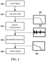
- FIG. 1 a flowchart shows a high-level representation of a speech enhancement process according to an example embodiment.
- An input signal 100 is provided by a transducer such as a microphone.
- the input signal 100 may be digitized via an analog-to-digital converter (ADC) for subsequent digital signal processing.
- ADC analog-to-digital converter
- the input signal 100 passes through a low-pass filter 102 which removes high-frequency components from the signal.
- the cutoff frequency for the filter 102 may be set within a range acceptable for speech processing. For example, traditional narrowband telephone speech is typically limited to around 3kHz, and so the cutoff frequency could be set at or near 3kHz. As will be described in greater detail below, the cutoff frequency can optionally be adapted during use, e.g., to account for changes in environmental noise.
- the low-pass filter 102 outputs a band-limited signal 102 that includes speech plus noise that is processed via a speech enhancement module 104.
- the speech enhancement module identifies components of the signal that correspond to speech and may, for example, increase the amplitude of the speech components relative to everything else in the signal 103, the latter which could include ambient noise, electrical noise, etc. Because the speech enhancement module 104 operates on a reduced bandwidth signal, it can have lower complexity than a larger bandwidth speech enhancer. Thus, a bandwidth limited speech enhancement module 104 can be more readily implemented in a resource-limited device such as a hearing aid.
- the result of processing by the speech enhancement module is an enhanced signal 105 in which speech can be heard more clearly over background noise and other nonspeech components.
- the enhanced signal 105 is still bandwidth limited, however, and therefore may be missing some high frequency components of the speech. This reduction in bandwidth may result, for example, in unvoiced/fricative sounds being muted or inaudible.
- the enhanced speech signal 105 is input to a bandwidth extender 106 that recovers and/or synthesizes high frequency content in the signal to create an increased bandwidth output signal 108.
- the increased bandwidth output signal 108 has an increase at least in high frequency portions of the speech signal, e.g., spectral bands above the cutoff frequency utilized by the low-pass filter 102.
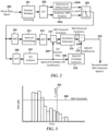
- FIG. 2 a block diagram illustrates a more detailed signal processing path according to an example embodiment.
- a noisy input signal 200 is digitized (not shown) and input to a windowing function 201 which assembles consecutive samples into a window, where part of each window may overlap with previous windows.
- the samples in each window are transformed into the frequency domain via a fast Fourier transform (FFT) 202.
- FFT fast Fourier transform
- a posteriori SNR analysis 203a provides an estimate of signal quality for a selected range of frequencies.
- the posteriori SNR analysis 203a can be used to select a cutoff frequency f_cutoff used by a low-pass filter 204. This allows changing f_cutoff based on current noise characteristics of the input signal 200.
- f_cutoff can be a pre-set fixed value, and/or a userconfigurable fixed value, e.g., based on a user-selected setting from a control application.
- the posteriori SNR is one signal quality estimate that can be used to reevaluate f_cutoff.
- a coherent-to-diffuse power ratio (CDR) 203b can be used instead of or in addition to the posteriori SNR analysis 203a for determining f_cutoff.
- the CDR analysis 203ba is a sub-band analysis that assists in clarifying speech in highly reverberant environments.
- the CDR analysis 203b can be used to generate an input for DNN-based dereverberation. If DNN-based noise reduction and dereverberation are implemented simultaneously, a combination of the outputs of posteriori SNR analysis 203a and CDR analysis 203b can be used to determine the f_cutoff.
- the low-pass cutoff filter 204 generally separates high and low frequency components used in subsequent stages of the speech enhancement processing.
- One reason to separate the high-band from the low-band is that noisy speech in real-world has frequencydependent SNR, e.g., higher SNR in low bands due to the main presence of speech and lower SNR in high bands. Because of lower SNR at high bands, there higher risk of damaging speech (e.g., introducing distortion) when attempting to remove noise on the wideband signal. Therefore, using the narrowband, lower frequency signal for speech enhancement reduces risk of creating distortion when conducting speech enhancement. Also, as noted above, use of the lower frequency band can reduce computational complexity of the speech enhancement algorithm, which can be useful in low power devices.
- the ASE processor 205 may be, in one embodiment, a DNN-based speech enhancer including noise reduction and dereverberation.
- Other machine learning algorithms may be used instead of or together with DNN-based speech enhancement, such as convolutional neural networks (SNN), recurrent neural networks (RNN), etc.
- a linear predictive coding (LPC) analysis 207 is conducted on the low-pass signal, which is converted back to the time domain by an inverse FFT (IFFT) 206.
- the LPC analysis 207 derives LPC coefficients 208 and LPC analysis filter 209 based on the narrow-band, noisy spectral envelope.
- the LPC coefficients 208 can be derived using auto-correlation method and are served as the inputs for spectral envelope extension 210.
- the spectral envelope extension 210 generally involves a identifying feature sets in the signal and mapping technique between narrow-band and wideband feature sets. Relevant methods for spectral envelope extension include linear mapping based on codebooks, Bayesian estimation methods and DNN-based mapping.
- a subset of the LPC coefficient 208 can selected for use by the spectral envelope extension based on a level of hearing loss of a user of the hearing assistance device. For example, if the user cannot hear frequencies higher than f h , then LPC coefficients affecting frequencies above f h may be omitted from the spectral envelope extension 210.
- the LPC analysis filter 209 is used for predicting the enhanced low-frequency excitation signal, which will serve as the input for excitation signal extension 215 for high frequency ranges.
- speech can be broken up into two parts: the excitation and the spectral envelope. In order to attain high quality wideband speech, both parts are typically extended.
- the excitation signal includes of impulsive components placed at pitch harmonics. Therefore, the speech signal is first broken up into frames and classified as voiced and unvoiced frames via spectral flatness measure. Then different modulation strategies apply for unvoiced and voiced frames.
- spectral modulation methods may be used, including spectral band replication and spectral folding.
- spectral envelope extension 210 extrapolates the narrowband spectral envelope to that of the reconstructed wideband speech spectral envelope. This problem generally involves finding the right feature set and the right mapping technique between narrowband and wideband feature sets.
- a spectral smoothing process 211 may be applied to the enhanced spectrum components at low frequency ranges that are output from the ASE processor 205.
- the spectral smoothing 211 is optional, and may deploy a moving window in the frequency domain in order to address spectrum discontinuity.
- the output of the spectral smoothing is inverse-transformed to the time domain via IFFT 212.
- the output of the IFFT 212 is filtered with the with LPC analysis filter 209 to get the excitation signal 214 based on the narrow-band enhanced signal.
- the wideband speech signal 218 is obtained by convolving 216 the wideband enhanced excitation signal 217 with the wideband LPC feature coefficients 219 (which are the output of spectral envelope extension 210).
- the cutoff frequency (f_cutoff) of the low-pass filter 204 defines what information in the input signal 200 is used for ASE processing 205 and which information is discarded.
- the cutoff frequency may be actively adjusted during use by monitoring the active posteriori-SNR estimates. These estimates determine a cut-off frequency where signal components higher than the cut-off frequency have a high risk of creating distortion when conducting speech enhancement.
- FIG. 3 a plot shows how posteriori-SNR estimates may be used to select cutoff frequencies according to an example embodiment.
- each of the bars represent the estimated posteriori-SNR for one of the analyzed bands.
- An SNR threshold 300 may be decided empirically (e.g., -6dB) and a cutoff frequency 301 may be selected that ensures frequency bands below the cutoff frequency 301 have an average SNR that is below SNR threshold 300.
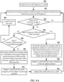
- a flowchart shows an example of how f_cutoff may be actively adjusted according to an example embodiment.
- the procedure involves initializing 400 the cut-off frequency.
- f_cutoff could be initially set to 3 kHz, which is an approximate upper limit on narrowband telephonic speech.
- the rest of the procedure evaluates conditions which might justify changing f_cutoff.
- There may be some practical limits on how much f_cutoff should change from this value e.g., no less than about 2.5kHz and no more than about 5kHz.
- the higher limit there may be reduced benefits in the ASE model processing frequencies that extend past the higher limit, as well as there possibly being excessive noise or less useful speech components above the higher limit.
- the average of posteriori-SNR estimates for frequency bands that are below the current cut-off frequency are calculated. This calculation is used to determine whether to set a new cutoff frequency as shown in blocks 404-410, which will be described in greater detail below. Setting a new cutoff frequency may have impacts in downstream processes in the signal path, and so block 402 is used to limit the frequency of cut-off frequency updates.
- the ASE processor 205 may include a machine learning model trained on spectra defined by a specific f_cutoff of the low pass filter 204. Therefore, a change in f_cutoff may involve making changes to the ASE processor 205 (see block 407 in FIG. 4 ), such as using a different set of weights and biases applied to a neural network, using a different network structure, etc. Such changes to the ASE processor 205 may be computationally expensive and may have other side effects, e.g., introducing unwanted artifacts into the audio stream. As a result, if f_cutoff is changeable during use, the system may introduce some checks to ensure that f_cutoff does not change too frequently.
- the decision block 402 checks whether the last change to f_cutoff occurred greater than a minimum elapsed time t_min. If so, then a new f_cutoff can be calculated and used as shown in subsequent blocks.
- elapsed time is only one example of how to limit "churning" of f_cutoff.
- a running average of the posteriori-SNR estimates calculated at block 401 could be used to determine whether changes to the noise profile is shorter term or longer term, and this could be used with or without elapsed time checks.
- the elapsed time could be checked elsewhere in the program loop. For example, after a change in f_cutoff, the calculation of SNR at block 401 could be suspended until at least time t_min has elapsed.
- block 402 returns 'yes,' a decision whether to change f_cutoff begins at block 404.
- the predetermined SNR threshold e.g., -6 dB
- Blocks 405-406 detail how a new f_cutoff can be calculated. Generally, this involves iteratively calculating 405 the average posteriori SNR by individually adding the sub-band posteriori-SNR estimates beyond f_cutoff into consideration until the average of posteriori-SNR estimates is smaller than the SNR threshold.
- the value of f_cutoff is updated 406 with the center frequency of the lastly added sub-band in block 405, which would generally correspond to the highest frequencies of the newly considered sub-bands.
- a second check may be made as shown at block 408 to see of the average SNR estimate is smaller than a second threshold (e.g., -9dB). If not, then the average of posteriori-SNR estimate is within an acceptable range and f_cutoff remains the same as shown in block 403. If block 408 returns 'yes," then the average SNR estimate may be too low, and as shown in block 409, the average SNR is recalculated by removing high frequency sub-bands until the SNR estimate is less than the second threshold.
- a second threshold e.g., -9dB
- f_cutoff is updated with the center frequency of the highest remaining sub-band.
- block 410 could involve reverting the value of f_cutoff to the initial value set in block 400. If f_cutoff is changed at blocks 406 or 410, this may also require updating 407 the ASE model based on the new f_cutoff. Other system components may also be changed in response to a change in f_cutoff, such as the LPC analyzer 207 shown in FIG. 2 .
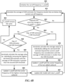
- FIG. 4A a flowchart shows an example of how f_cutoff may be actively adjusted based on CDR according to another example embodiment.
- the procedure could be implemented separately or together with the procedure in FIG. 4A . In the latter case, some operations may be merged, such as initializing 400, 420 the cut-off frequency, determining elapsed time (or other condition) since last update of f_cutoff 402, 422, and updating 407, 427 the ASE model with a new f_cutoff.
- the average of CDR estimates for frequency bands that are below the current cut-off frequency are calculated.
- the decision block 422 checks whether the last change to f_cutoff occurred greater than a minimum elapsed time t_min, or some other criteria is described as in relation to FIG. 4A . Once sufficient time has passed (and/or other criteria are satisfied) and block 422 returns 'yes,' a decision whether to change f_cutoff begins at block 424.
- Blocks 425-426 detail how a new f_cutoff can be calculated. Generally, this involves iteratively calculating 425 the average CDR by individually adding the sub-band CDR estimates beyond f_cutoff into consideration until the average of CDR estimates is smaller than the CDR threshold. The value of f_cutoff is updated 426 with the center frequency of the lastly added sub-band in block 425, which would generally correspond to the highest frequencies of the newly considered sub-bands.
- a second check may be made as shown at block 428 to see of the average CDR estimate is smaller than a second threshold. If not, then the average of CDR estimate is within an acceptable range and f_cutoff remains the same as shown in block 423. If block 428 returns "yes,” then the average CDR estimate may be too low, and as shown in block 429, the average CDR is recalculated by removing high frequency sub-bands until the CDR estimate is less than the second threshold. At block 430, f_cutoff is updated with the center frequency of the highest remaining sub-band.
- block 430 could involve reverting the value of f_cutoff to the initial value set in block 420. If f_cutoff is changed at blocks 426 or 430, this may also require updating 427 the ASE model based on the new f_cutoff. Other system components may also be changed in response to a change in f_cutoff, such as the LPC analyzer 207 shown in FIG. 2 .
- a speech enhancement scheme utilizes advanced speech enhancement processing for low frequency bands and BWE for high frequency bands.
- the bandwidth extension scheme provides improved speech enhancement or de-noising tool in the high frequency bands.
- Using just the low frequency bands for speech enhancement reduces the complexity of advanced enhancement schemes.
- An optional adaptive scheme can actively adjust the cut-off frequency that separates the high and low frequency bands based on the estimate of posteriori SNR and/or CDR (which are typically calculated in classic speech enhancement schemes). These implementations can be used in any ear-worn electronic device, such as a hearing aid.
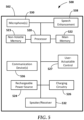
- FIG. 5 a block diagram illustrates an ear-worn electronic device 500 in accordance with any of the embodiments disclosed herein.
- the hearing device 500 includes a housing 502 configured to be worn in, on, or about an ear of a wearer.
- the hearing device 500 shown in FIG. 5 can represent a single hearing device configured for monaural or singleear operation or one of a pair of hearing devices configured for binaural or dual-ear operation.
- the hearing device 500 shown in FIG. 5 includes a housing 502 within or on which various components are situated or supported.
- the housing 502 can be configured for deployment on a wearer's ear (e.g., a behind-the-ear device housing), within an ear canal of the wearer's ear (e.g., an in-the-ear, in-the-canal, invisible-in-canal, or completely-in-the-canal device housing) or both on and in a wearer's ear (e.g., a receiver-in-canal or receiver-in-the-ear device housing).
- a wearer's ear e.g., a behind-the-ear device housing
- both on and in a wearer's ear e.g., a receiver-in-canal or receiver-in-the-ear device housing.
- the hearing device 500 includes a processor 520 operatively coupled to a main memory 522 and a non-volatile memory 523.
- the processor 520 can be implemented as one or more of a multi-core processor, a digital signal processor (DSP), a microprocessor, a programmable controller, a general-purpose computer, a special-purpose computer, a hardware controller, a software controller, a combined hardware and software device, such as a programmable logic controller, and a programmable logic device (e.g., FPGA, ASIC).
- the processor 520 can include or be operatively coupled to main memory 522, such as RAM (e.g., DRAM, SRAM).
- the processor 520 can include or be operatively coupled to non-volatile memory 523, such as ROM, EPROM, EEPROM or flash memory.
- non-volatile memory 523 such as ROM, EPROM, EEPROM or flash memory.
- the non-volatile memory 523 is configured to store instructions that facilitate ASE on a low-band signal and BWE to recover/synthesize high frequencies for audio reproduction.
- the hearing device 500 includes an audio processing facility operably coupled to, or incorporating, the processor 520.
- the audio processing facility includes audio signal processing circuitry (e.g., analog front-end, analog-to-digital converter, digital-to-analog converter, DSP, and various analog and digital filters), a microphone arrangement 530, and a speaker or receiver 532.
- the microphone arrangement 530 can include one or more discrete microphones or a microphone array(s) (e.g., configured for microphone array beamforming). Each of the microphones of the microphone arrangement 530 can be situated at different locations of the housing 502. It is understood that the term microphone used herein can refer to a single microphone or multiple microphones unless specified otherwise.
- the hearing device 500 may also include a user interface with a user-actuatable control 527 operatively coupled to the processor 520.
- the user-actuatable control 527 is configured to receive an input from the wearer of the hearing device 500.
- the input from the wearer can be any type of user input, such as a touch input, a gesture input, or a voice input.
- the user-actuatable control 527 may be configured to receive an input from the wearer of the hearing device 500 to change speech enhancement parameters of the hearing device 500, such as enabling/disabling of speech enhancement, fixed or adaptable cutoff frequency, etc.
- Other parameters, such as upper and lower bounds the adaptable cutoff frequency may be set by a user or technician, e.g., to adapt performance to suit the level of hearing impairment of the user of the device.
- the hearing device 500 also includes a speech enhancement module 538 operably coupled to the processor 520.
- the speech enhancement module 538 can be implemented in software, hardware, or a combination of hardware and software.
- the speech enhancement module 538 can be a component of, or integral to, the processor 520 or another processor (e.g., a DSP) coupled to the processor 520.
- the speech enhancement module 538 is configured to detect speech in different types of acoustic environments.
- the different types of sound can include speech, music, and several different types of noise (e.g., wind, transportation noise and vehicles, machinery), etc., and combinations of these and other sounds (e.g., transportation noise with speech).
- the speech enhancement module 538 can be configured to filter out audio signals above a cutoff frequency such that only a lower frequency component of the audio signals is subject to speech enhancement via a machine learning algorithm.
- Such machine learning enhancement may be performed, for example, via a DNN, CNN, RNN, etc.
- these neural networks are trained to detect speech patterns in the presence of noise, and can be used to improve the detectability of the speech by a listener through isolation and amplification of the speech patterns and/or attenuation of the noise.
- the hearing device 500 can include one or more communication devices 536 coupled to one or more antenna arrangements.
- the one or more communication devices 536 can include one or more radios that conform to an IEEE 802.11 (e.g., WiFi ® ) or Bluetooth ® (e.g., BLE, Bluetooth ® 4. 2, 5.0, 5.1, 5.2 or later) specification, for example.
- the hearing device 500 can include a near-field magnetic induction (NFMI) sensor (e.g., an NFMI transceiver coupled to a magnetic antenna) for effecting shortrange communications (e.g., ear-to-ear communications, ear-to-kiosk communications).
- NFMI near-field magnetic induction
- the hearing device 500 also includes a power source, which can be a conventional battery, a rechargeable battery (e.g., a lithium-ion battery), or a power source comprising a supercapacitor.
- a power source which can be a conventional battery, a rechargeable battery (e.g., a lithium-ion battery), or a power source comprising a supercapacitor.
- the hearing device 500 includes a rechargeable power source 524 which is operably coupled to power management circuitry for supplying power to various components of the hearing device 500.
- the rechargeable power source 524 is coupled to charging circuity 526.
- the charging circuitry 526 is electrically coupled to charging contacts on the housing 502 which are configured to electrically couple to corresponding charging contacts of a charging unit when the hearing device 500 is placed in the charging unit.
- Coupled refers to elements being attached to each other either directly (in direct contact with each other) or indirectly (having one or more elements between and attaching the two elements). Either term may be modified by "operatively” and “operably,” which may be used interchangeably, to describe that the coupling or connection is configured to allow the components to interact to carry out at least some functionality (for example, a radio chip may be operably coupled to an antenna element to provide a radio frequency electric signal for wireless communication).
- orientation such as “top,” “bottom,” “side,” and “end,” are used to describe relative positions of components and are not meant to limit the orientation of the embodiments contemplated.
- an embodiment described as having a “top” and “bottom” also encompasses embodiments thereof rotated in various directions unless the content clearly dictates otherwise.
- references to "one embodiment,” “an embodiment,” “certain embodiments,” or “some embodiments,” etc. means that a particular feature, configuration, composition, or characteristic described in connection with the embodiment is included in at least one embodiment of the disclosure. Thus, the appearances of such phrases in various places throughout are not necessarily referring to the same embodiment of the disclosure. Furthermore, the particular features, configurations, compositions, or characteristics may be combined in any suitable manner in one or more embodiments.
- phrases "at least one of,” “comprises at least one of,” and “one or more of” followed by a list refers to any one of the items in the list and any combination of two or more items in the list.
Landscapes
- Engineering & Computer Science (AREA)
- Physics & Mathematics (AREA)
- Acoustics & Sound (AREA)
- Signal Processing (AREA)
- Health & Medical Sciences (AREA)
- Computational Linguistics (AREA)
- Quality & Reliability (AREA)
- Audiology, Speech & Language Pathology (AREA)
- Human Computer Interaction (AREA)
- Multimedia (AREA)
- Artificial Intelligence (AREA)
- Automation & Control Theory (AREA)
- Evolutionary Computation (AREA)
- Fuzzy Systems (AREA)
- Mathematical Physics (AREA)
- Software Systems (AREA)
- General Health & Medical Sciences (AREA)
- Neurosurgery (AREA)
- Otolaryngology (AREA)
- Telephone Function (AREA)
- Circuit For Audible Band Transducer (AREA)
Claims (14)
- Verfahren, umfassend:Empfangen (100) eines digitalisierten Signals, das Sprache beinhaltet;Anwenden (102) eines Tiefpassfilters auf das digitalisierte Signal, um eine Hochfrequenzkomponente zu entfernen und eine Niederfrequenzkomponente zu erhalten;Anwenden (104) einer Sprachverbesserung auf die Niederfrequenzkomponente;Anwenden (106) einer blinden Bandbreitenerweiterung auf die verbesserte Niederfrequenzkomponente, um eine bandbreitenerweiterte Hochfrequenzkomponente zu erhalten, die eine Schätzung der Hochfrequenzkomponente ist; undAusgeben (108) an einen Lautsprecher einer am Ohr tragbaren Vorrichtung (500) eines verbesserten Sprachsignals, das eine Kombination aus der verbesserten Niederfrequenzkomponente und der bandbreitenerweiterten Hochfrequenzkomponente ist,wobei eine Grenzfrequenz des Tiefpassfilters während einer Verwendung der am Ohr tragbaren Vorrichtung (500) aktualisiert wird,wobei die Grenzfrequenz basierend auf einer Änderung in Signalqualitätsschätzungen für Frequenzbänder unterhalb der Grenzfrequenz aktualisiert wird, undwobei die Signalqualitätsschätzungen mindestens eines von einem a-posteriori-Signal-Rausch-Verhältnis (SNR) und einem kohärent-diffusen Leistungsverhältnis (CDR) umfassen.
- Verfahren nach Anspruch 1, das weiter Durchführen einer linearen prädiktiven Codierung 'LPC' auf dem digitalisierten Signal, nachdem der Tiefpassfilter angewendet worden ist, umfasst, wobei ein Analysefilter der LPC zum Vorhersagen eines verbesserten niederfrequenten Anregungssignals verwendet wird, das als Eingabe zur Anregungssignalerweiterung verwendet wird.
- Verfahren nach Anspruch 2, wobei Koeffizienten der LPC verwendet werden, um eine spektrale Hüllkurve eines Ausgangs der Anregungssignalerweiterung zu erweitern, wobei vorzugsweise eine Teilmenge der LPC-Koeffizienten für eine spektrale Hüllkurvenerweiterung basierend auf einem Grad des Hörverlusts eines Benutzers der am Ohr tragbaren elektronischen Vorrichtung (500) ausgewählt wird.
- Verfahren nach einem der Ansprüche 1-3, wobei die Sprachverbesserung in einem Frequenzbereich durchgeführt wird und die blinde Bandbreitenerweiterung in einem Zeitbereich durchgeführt wird; und/oderwobei die Sprachverbesserung von einem neuronalen Netzwerk durchgeführt wird; und/oderwobei das Entfernen der Hochfrequenzkomponente eine Komplexität der Sprachverbesserung reduziert.
- Verfahren nach Anspruch 1, wobei die Grenzfrequenz aktualisiert wird, wenn der Durchschnitt der Signalqualitätsschätzungen für Frequenzbänder unterhalb der Grenzfrequenz größer als ein Schwellenwert ist;
wobei vorzugsweise ein neuer Wert der Grenzfrequenz basierend auf iterativem Aktualisieren des Durchschnitts mit Signalqualitätsschätzungen zusätzlicher Teilbänder bestimmt wird, die größer sind als die Grenzfrequenz, bis der aktualisierte Durchschnitt kleiner ist als der Schwellenwert, wobei der neue Wert der Grenzfrequenz auf einem Teilband mit der höchsten Frequenz der zusätzlichen Teilbänder basiert. - Verfahren nach einem der Ansprüche 1-4, wobei die Grenzfrequenz basierend auf einer Änderung des kohärent-diffusen Verhältnisses der digitalisierten Sprache aktualisiert wird.
- Verfahren nach einem der Ansprüche 1-4, wobei die Grenzfrequenz basierend auf einer Kombination aktualisiert wird, von:einer Änderung in Schätzungen des a-posteriori-Signal-Rausch-Verhältnisses 'SNR' für Frequenzbänder unterhalb der Grenzfrequenz; undeiner Änderung des kohärent-diffusen Verhältnisses 'CDR' der digitalisierten Sprache.
- Am Ohr tragbare elektronische Vorrichtung (500), umfassend:mindestens ein Mikrofon (530), das konfiguriert ist, um Schall, der Sprache beinhaltet, in ein elektrisches Signal umzuwandeln;einen Lautsprecher (532);einen Analog-Digital-Wandler, der das elektrische Signal in ein digitalisiertes Signal umwandelt; undeinen Prozessor (520), der mit dem Mikrofon (530), dem Lautsprecher (532) und dem Analog-Digital-Wandler wirkgekoppelt ist, wobei der Prozessor (520) betreibbar ist, um:einen Tiefpassfilter auf das digitalisierte Signal anzuwenden (102), um eine Hochfrequenzkomponente zu entfernen und eine Niederfrequenzkomponente zu erhalten;Anwenden (104) einer Sprachverbesserung auf die Niederfrequenzkomponente;Anwenden (106) einer blinden Bandbreitenerweiterung auf die verbesserte Niederfrequenzkomponente, um eine Schätzung zumindest eines Teils der Hochfrequenzkomponente wiederherzustellen oder zu synthetisieren; undein verbessertes Sprachsignal über den Lautsprecher (532) auszugeben (108), das eine Kombination aus der verbesserten Niederfrequenzkomponente und der bandbreitenerweiterten Hochfrequenzkomponente ist,wobei eine Grenzfrequenz des Tiefpassfilters während einer Verwendung der am Ohr tragbaren Vorrichtung (500) aktualisiert wird,wobei die Grenzfrequenz basierend auf einer Änderung in Signalqualitätsschätzungen für Frequenzbänder unterhalb der Grenzfrequenz aktualisiert wird, undwobei die Signalqualitätsschätzungen mindestens eines von einem a-posteriori-Signal-Rausch-Verhältnis (SNR) und einem kohärent-diffusen Leistungsverhältnis (CDR) umfassen.
- Am Ohr tragbare elektronische Vorrichtung (500) nach Anspruch 8, wobei der Prozessor (520) weiter konfiguriert ist, um eine lineare prädiktive Codierung 'LPC' auf dem digitalisierten Signal durchzuführen, nachdem der Tiefpassfilter angewendet worden ist, wobei ein Analysefilter der LPC zum Vorhersagen eines verbesserten niederfrequenten Anregungssignals verwendet wird, das als Eingabe zur Anregungssignalerweiterung verwendet wird.
- Am Ohr tragbare elektronische Vorrichtung (500) nach Anspruch 9, wobei Koeffizienten der LPC verwendet werden, um eine spektrale Hüllkurve eines Ausgangs der Anregungssignalerweiterung zu erweitern, wobei vorzugsweise eine Teilmenge der LPC-Koeffizienten für eine spektrale Hüllkurvenerweiterung basierend auf einem Grad des Hörverlusts eines Benutzers der am Ohr tragbaren Vorrichtung (500) ausgewählt wird.
- Am Ohr tragbare elektronische Vorrichtung (500) nach einem der Ansprüche 8-10, wobei die Sprachverbesserung in einem Frequenzbereich durchgeführt wird und die blinde Bandbreitenerweiterung in einem Zeitbereich durchgeführt wird; und/oderwobei die Sprachverbesserung von einem neuronalen Netzwerk durchgeführt wird; und/oderwobei das Entfernen der Hochfrequenzkomponente eine Komplexität der Sprachverbesserung reduziert.
- Am Ohr tragbare elektronische Vorrichtung (500) nach einem der Ansprüche 8-11,wobei die Grenzfrequenz aktualisiert wird, wenn der Durchschnitt der Signalqualitätsschätzungen für Frequenzbänder unterhalb der Grenzfrequenz größer als ein Schwellenwert ist;wobei bevorzugter ein neuer Wert der Grenzfrequenz basierend auf iterativem Aktualisieren des Durchschnitts mit Signalqualitätsschätzungen zusätzlicher Teilbänder bestimmt wird, die größer sind als die Grenzfrequenz, bis der aktualisierte Durchschnitt kleiner ist als der Schwellenwert, wobei der neue Wert der Grenzfrequenz auf einem Teilband mit der höchsten Frequenz der zusätzlichen Teilbänder basiert.
- Am Ohr tragbare elektronische Vorrichtung (500) nach einem der Ansprüche 8-11, wobei die Grenzfrequenz basierend auf einer Änderung des kohärent-diffusen Verhältnisses der digitalisierten Sprache aktualisiert wird.
- Am Ohr tragbare elektronische Vorrichtung (500) nach einem der Ansprüche 8-11, wobei die Grenzfrequenz basierend auf einer Kombination aktualisiert wird, von:einer Änderung in Schätzungen des a-posteriori-Signal-Rausch-Verhältnisses 'SNR' für Frequenzbänder unterhalb der Grenzfrequenz; undeiner Änderung des kohärent-diffusen Verhältnisses 'CDR' der digitalisierten Sprache.
Applications Claiming Priority (2)
| Application Number | Priority Date | Filing Date | Title |
|---|---|---|---|
| US202063007613P | 2020-04-09 | 2020-04-09 | |
| PCT/US2021/025883 WO2021207131A1 (en) | 2020-04-09 | 2021-04-06 | Reduced-bandwidth speech enhancement with bandwidth extension |
Publications (2)
| Publication Number | Publication Date |
|---|---|
| EP4133482A1 EP4133482A1 (de) | 2023-02-15 |
| EP4133482B1 true EP4133482B1 (de) | 2025-05-28 |
Family
ID=75690668
Family Applications (1)
| Application Number | Title | Priority Date | Filing Date |
|---|---|---|---|
| EP21722025.0A Active EP4133482B1 (de) | 2020-04-09 | 2021-04-06 | Sprachverbesserung mit reduzierter bandbreite und bandbreitenerweiterung |
Country Status (2)
| Country | Link |
|---|---|
| EP (1) | EP4133482B1 (de) |
| WO (1) | WO2021207131A1 (de) |
Families Citing this family (3)
| Publication number | Priority date | Publication date | Assignee | Title |
|---|---|---|---|---|
| CN117292699B (zh) * | 2022-06-17 | 2025-10-28 | 华为技术有限公司 | 音频的带宽扩展方法、装置、存储介质及计算机程序产品 |
| EP4303873B1 (de) | 2022-07-04 | 2025-05-21 | GN Audio A/S | Personalisierte bandbreitenerweiterung |
| CN116453536B (zh) * | 2023-04-28 | 2025-09-26 | 歌尔股份有限公司 | 风噪抑制方法、装置、设备及计算机可读存储介质 |
Citations (3)
| Publication number | Priority date | Publication date | Assignee | Title |
|---|---|---|---|---|
| US5285502A (en) * | 1992-03-31 | 1994-02-08 | Auditory System Technologies, Inc. | Aid to hearing speech in a noisy environment |
| JPH06177683A (ja) * | 1992-11-30 | 1994-06-24 | Rion Co Ltd | 音調整装置 |
| US20190200143A1 (en) * | 2016-05-30 | 2019-06-27 | Oticon A/S | Audio processing device and a method for estimating a signal-to-noise-ratio of a sound signal |
Family Cites Families (1)
| Publication number | Priority date | Publication date | Assignee | Title |
|---|---|---|---|---|
| DK2211339T3 (en) * | 2009-01-23 | 2017-08-28 | Oticon As | listening System |
-
2021
- 2021-04-06 EP EP21722025.0A patent/EP4133482B1/de active Active
- 2021-04-06 WO PCT/US2021/025883 patent/WO2021207131A1/en not_active Ceased
Patent Citations (3)
| Publication number | Priority date | Publication date | Assignee | Title |
|---|---|---|---|---|
| US5285502A (en) * | 1992-03-31 | 1994-02-08 | Auditory System Technologies, Inc. | Aid to hearing speech in a noisy environment |
| JPH06177683A (ja) * | 1992-11-30 | 1994-06-24 | Rion Co Ltd | 音調整装置 |
| US20190200143A1 (en) * | 2016-05-30 | 2019-06-27 | Oticon A/S | Audio processing device and a method for estimating a signal-to-noise-ratio of a sound signal |
Also Published As
| Publication number | Publication date |
|---|---|
| US20230169987A1 (en) | 2023-06-01 |
| WO2021207131A1 (en) | 2021-10-14 |
| EP4133482A1 (de) | 2023-02-15 |
Similar Documents
| Publication | Publication Date | Title |
|---|---|---|
| EP3694229B1 (de) | Hörgerät mit einem geräuschreduzierungssystem | |
| CN110060666B (zh) | 听力装置的运行方法及基于用语音可懂度预测算法优化的算法提供语音增强的听力装置 | |
| EP3701525B1 (de) | Elektronische vorrichtung mit einer zusammengesetzten metrik zur klangverbesserung | |
| US9064502B2 (en) | Speech intelligibility predictor and applications thereof | |
| EP3255634B1 (de) | Audioverarbeitungsvorrichtung und verfahren zur schätzung des signal-rausch-verhältnisses eines tonsignals | |
| Hamacher et al. | Signal processing in high-end hearing aids: State of the art, challenges, and future trends | |
| AU771444B2 (en) | Noise reduction apparatus and method | |
| CN107147981B (zh) | 单耳侵入语音可懂度预测单元、助听器及双耳助听器系统 | |
| CN111131947A (zh) | 耳机信号处理方法、系统和耳机 | |
| EP4133482B1 (de) | Sprachverbesserung mit reduzierter bandbreite und bandbreitenerweiterung | |
| CN103874002A (zh) | 包括非自然信号减少的音频处理装置 | |
| US12340789B2 (en) | Hearing apparatus with bone conduction sensor | |
| JP2004312754A (ja) | 両耳信号増強システム | |
| WO2022051032A1 (en) | Mobile device that provides sound enhancement for hearing device | |
| US8948424B2 (en) | Hearing device and method for operating a hearing device with two-stage transformation | |
| JP6391198B2 (ja) | 補聴器システムの動作方法および補聴器システム | |
| US20090257609A1 (en) | Method for Noise Reduction and Associated Hearing Device | |
| CN107454537B (zh) | 包括滤波器组和起始检测器的听力装置 | |
| CN115209331A (zh) | 包括降噪系统的听力装置 | |
| US11671767B2 (en) | Hearing aid comprising a feedback control system | |
| US8422707B2 (en) | Spectral content modification for robust feedback channel estimation | |
| Puder | Hearing aids: an overview of the state-of-the-art, challenges, and future trends of an interesting audio signal processing application | |
| EP4303873B1 (de) | Personalisierte bandbreitenerweiterung | |
| CN107113517B (zh) | 操作助听器系统的方法和助听器系统 | |
| US20080175423A1 (en) | Adjusting a hearing apparatus to a speech signal |
Legal Events
| Date | Code | Title | Description |
|---|---|---|---|
| STAA | Information on the status of an ep patent application or granted ep patent |
Free format text: STATUS: UNKNOWN |
|
| STAA | Information on the status of an ep patent application or granted ep patent |
Free format text: STATUS: THE INTERNATIONAL PUBLICATION HAS BEEN MADE |
|
| PUAI | Public reference made under article 153(3) epc to a published international application that has entered the european phase |
Free format text: ORIGINAL CODE: 0009012 |
|
| STAA | Information on the status of an ep patent application or granted ep patent |
Free format text: STATUS: REQUEST FOR EXAMINATION WAS MADE |
|
| 17P | Request for examination filed |
Effective date: 20221017 |
|
| AK | Designated contracting states |
Kind code of ref document: A1 Designated state(s): AL AT BE BG CH CY CZ DE DK EE ES FI FR GB GR HR HU IE IS IT LI LT LU LV MC MK MT NL NO PL PT RO RS SE SI SK SM TR |
|
| DAV | Request for validation of the european patent (deleted) | ||
| DAX | Request for extension of the european patent (deleted) | ||
| STAA | Information on the status of an ep patent application or granted ep patent |
Free format text: STATUS: EXAMINATION IS IN PROGRESS |
|
| 17Q | First examination report despatched |
Effective date: 20240301 |
|
| GRAP | Despatch of communication of intention to grant a patent |
Free format text: ORIGINAL CODE: EPIDOSNIGR1 |
|
| STAA | Information on the status of an ep patent application or granted ep patent |
Free format text: STATUS: GRANT OF PATENT IS INTENDED |
|
| INTG | Intention to grant announced |
Effective date: 20250218 |
|
| GRAS | Grant fee paid |
Free format text: ORIGINAL CODE: EPIDOSNIGR3 |
|
| GRAA | (expected) grant |
Free format text: ORIGINAL CODE: 0009210 |
|
| STAA | Information on the status of an ep patent application or granted ep patent |
Free format text: STATUS: THE PATENT HAS BEEN GRANTED |
|
| P01 | Opt-out of the competence of the unified patent court (upc) registered |
Free format text: CASE NUMBER: APP_17595/2025 Effective date: 20250410 |
|
| AK | Designated contracting states |
Kind code of ref document: B1 Designated state(s): AL AT BE BG CH CY CZ DE DK EE ES FI FR GB GR HR HU IE IS IT LI LT LU LV MC MK MT NL NO PL PT RO RS SE SI SK SM TR |
|
| REG | Reference to a national code |
Ref country code: GB Ref legal event code: FG4D |
|
| REG | Reference to a national code |
Ref country code: CH Ref legal event code: EP |
|
| REG | Reference to a national code |
Ref country code: IE Ref legal event code: FG4D Ref country code: DE Ref legal event code: R096 Ref document number: 602021031426 Country of ref document: DE |
|
| REG | Reference to a national code |
Ref country code: NL Ref legal event code: MP Effective date: 20250528 |
|
| PG25 | Lapsed in a contracting state [announced via postgrant information from national office to epo] |
Ref country code: ES Free format text: LAPSE BECAUSE OF FAILURE TO SUBMIT A TRANSLATION OF THE DESCRIPTION OR TO PAY THE FEE WITHIN THE PRESCRIBED TIME-LIMIT Effective date: 20250528 Ref country code: FI Free format text: LAPSE BECAUSE OF FAILURE TO SUBMIT A TRANSLATION OF THE DESCRIPTION OR TO PAY THE FEE WITHIN THE PRESCRIBED TIME-LIMIT Effective date: 20250528 |
|
| REG | Reference to a national code |
Ref country code: LT Ref legal event code: MG9D |
|
| PG25 | Lapsed in a contracting state [announced via postgrant information from national office to epo] |
Ref country code: NO Free format text: LAPSE BECAUSE OF FAILURE TO SUBMIT A TRANSLATION OF THE DESCRIPTION OR TO PAY THE FEE WITHIN THE PRESCRIBED TIME-LIMIT Effective date: 20250828 Ref country code: GR Free format text: LAPSE BECAUSE OF FAILURE TO SUBMIT A TRANSLATION OF THE DESCRIPTION OR TO PAY THE FEE WITHIN THE PRESCRIBED TIME-LIMIT Effective date: 20250829 |
|
| PG25 | Lapsed in a contracting state [announced via postgrant information from national office to epo] |
Ref country code: NL Free format text: LAPSE BECAUSE OF FAILURE TO SUBMIT A TRANSLATION OF THE DESCRIPTION OR TO PAY THE FEE WITHIN THE PRESCRIBED TIME-LIMIT Effective date: 20250528 Ref country code: PL Free format text: LAPSE BECAUSE OF FAILURE TO SUBMIT A TRANSLATION OF THE DESCRIPTION OR TO PAY THE FEE WITHIN THE PRESCRIBED TIME-LIMIT Effective date: 20250528 |
|
| PG25 | Lapsed in a contracting state [announced via postgrant information from national office to epo] |
Ref country code: BG Free format text: LAPSE BECAUSE OF FAILURE TO SUBMIT A TRANSLATION OF THE DESCRIPTION OR TO PAY THE FEE WITHIN THE PRESCRIBED TIME-LIMIT Effective date: 20250528 |
|
| PG25 | Lapsed in a contracting state [announced via postgrant information from national office to epo] |
Ref country code: HR Free format text: LAPSE BECAUSE OF FAILURE TO SUBMIT A TRANSLATION OF THE DESCRIPTION OR TO PAY THE FEE WITHIN THE PRESCRIBED TIME-LIMIT Effective date: 20250528 |
|
| PG25 | Lapsed in a contracting state [announced via postgrant information from national office to epo] |
Ref country code: RS Free format text: LAPSE BECAUSE OF FAILURE TO SUBMIT A TRANSLATION OF THE DESCRIPTION OR TO PAY THE FEE WITHIN THE PRESCRIBED TIME-LIMIT Effective date: 20250828 |
|
| PG25 | Lapsed in a contracting state [announced via postgrant information from national office to epo] |
Ref country code: IS Free format text: LAPSE BECAUSE OF FAILURE TO SUBMIT A TRANSLATION OF THE DESCRIPTION OR TO PAY THE FEE WITHIN THE PRESCRIBED TIME-LIMIT Effective date: 20250928 |
|
| PG25 | Lapsed in a contracting state [announced via postgrant information from national office to epo] |
Ref country code: LV Free format text: LAPSE BECAUSE OF FAILURE TO SUBMIT A TRANSLATION OF THE DESCRIPTION OR TO PAY THE FEE WITHIN THE PRESCRIBED TIME-LIMIT Effective date: 20250528 |
|
| REG | Reference to a national code |
Ref country code: AT Ref legal event code: MK05 Ref document number: 1799106 Country of ref document: AT Kind code of ref document: T Effective date: 20250528 |
|
| PG25 | Lapsed in a contracting state [announced via postgrant information from national office to epo] |
Ref country code: DK Free format text: LAPSE BECAUSE OF FAILURE TO SUBMIT A TRANSLATION OF THE DESCRIPTION OR TO PAY THE FEE WITHIN THE PRESCRIBED TIME-LIMIT Effective date: 20250528 Ref country code: SM Free format text: LAPSE BECAUSE OF FAILURE TO SUBMIT A TRANSLATION OF THE DESCRIPTION OR TO PAY THE FEE WITHIN THE PRESCRIBED TIME-LIMIT Effective date: 20250528 Ref country code: AT Free format text: LAPSE BECAUSE OF FAILURE TO SUBMIT A TRANSLATION OF THE DESCRIPTION OR TO PAY THE FEE WITHIN THE PRESCRIBED TIME-LIMIT Effective date: 20250528 |
|
| PG25 | Lapsed in a contracting state [announced via postgrant information from national office to epo] |
Ref country code: CZ Free format text: LAPSE BECAUSE OF FAILURE TO SUBMIT A TRANSLATION OF THE DESCRIPTION OR TO PAY THE FEE WITHIN THE PRESCRIBED TIME-LIMIT Effective date: 20250528 |
|
| PG25 | Lapsed in a contracting state [announced via postgrant information from national office to epo] |
Ref country code: EE Free format text: LAPSE BECAUSE OF FAILURE TO SUBMIT A TRANSLATION OF THE DESCRIPTION OR TO PAY THE FEE WITHIN THE PRESCRIBED TIME-LIMIT Effective date: 20250528 |
|
| PG25 | Lapsed in a contracting state [announced via postgrant information from national office to epo] |
Ref country code: SK Free format text: LAPSE BECAUSE OF FAILURE TO SUBMIT A TRANSLATION OF THE DESCRIPTION OR TO PAY THE FEE WITHIN THE PRESCRIBED TIME-LIMIT Effective date: 20250528 |
|
| PG25 | Lapsed in a contracting state [announced via postgrant information from national office to epo] |
Ref country code: IT Free format text: LAPSE BECAUSE OF FAILURE TO SUBMIT A TRANSLATION OF THE DESCRIPTION OR TO PAY THE FEE WITHIN THE PRESCRIBED TIME-LIMIT Effective date: 20250528 |