EP4133303B1 - Lidar pixel with active polarization control - Google Patents
Lidar pixel with active polarization control Download PDFInfo
- Publication number
- EP4133303B1 EP4133303B1 EP21737311.7A EP21737311A EP4133303B1 EP 4133303 B1 EP4133303 B1 EP 4133303B1 EP 21737311 A EP21737311 A EP 21737311A EP 4133303 B1 EP4133303 B1 EP 4133303B1
- Authority
- EP
- European Patent Office
- Prior art keywords
- light
- arm
- polarization
- splitter
- phase shifter
- Prior art date
- Legal status (The legal status is an assumption and is not a legal conclusion. Google has not performed a legal analysis and makes no representation as to the accuracy of the status listed.)
- Active
Links
Images


Classifications
-
- G—PHYSICS
- G01—MEASURING; TESTING
- G01S—RADIO DIRECTION-FINDING; RADIO NAVIGATION; DETERMINING DISTANCE OR VELOCITY BY USE OF RADIO WAVES; LOCATING OR PRESENCE-DETECTING BY USE OF THE REFLECTION OR RERADIATION OF RADIO WAVES; ANALOGOUS ARRANGEMENTS USING OTHER WAVES
- G01S7/00—Details of systems according to groups G01S13/00, G01S15/00, G01S17/00
- G01S7/48—Details of systems according to groups G01S13/00, G01S15/00, G01S17/00 of systems according to group G01S17/00
- G01S7/481—Constructional features, e.g. arrangements of optical elements
- G01S7/4814—Constructional features, e.g. arrangements of optical elements of transmitters alone
-
- G—PHYSICS
- G01—MEASURING; TESTING
- G01S—RADIO DIRECTION-FINDING; RADIO NAVIGATION; DETERMINING DISTANCE OR VELOCITY BY USE OF RADIO WAVES; LOCATING OR PRESENCE-DETECTING BY USE OF THE REFLECTION OR RERADIATION OF RADIO WAVES; ANALOGOUS ARRANGEMENTS USING OTHER WAVES
- G01S7/00—Details of systems according to groups G01S13/00, G01S15/00, G01S17/00
- G01S7/48—Details of systems according to groups G01S13/00, G01S15/00, G01S17/00 of systems according to group G01S17/00
- G01S7/481—Constructional features, e.g. arrangements of optical elements
-
- B—PERFORMING OPERATIONS; TRANSPORTING
- B60—VEHICLES IN GENERAL
- B60W—CONJOINT CONTROL OF VEHICLE SUB-UNITS OF DIFFERENT TYPE OR DIFFERENT FUNCTION; CONTROL SYSTEMS SPECIALLY ADAPTED FOR HYBRID VEHICLES; ROAD VEHICLE DRIVE CONTROL SYSTEMS FOR PURPOSES NOT RELATED TO THE CONTROL OF A PARTICULAR SUB-UNIT
- B60W60/00—Drive control systems specially adapted for autonomous road vehicles
- B60W60/001—Planning or execution of driving tasks
-
- G—PHYSICS
- G01—MEASURING; TESTING
- G01S—RADIO DIRECTION-FINDING; RADIO NAVIGATION; DETERMINING DISTANCE OR VELOCITY BY USE OF RADIO WAVES; LOCATING OR PRESENCE-DETECTING BY USE OF THE REFLECTION OR RERADIATION OF RADIO WAVES; ANALOGOUS ARRANGEMENTS USING OTHER WAVES
- G01S17/00—Systems using the reflection or reradiation of electromagnetic waves other than radio waves, e.g. lidar systems
- G01S17/02—Systems using the reflection of electromagnetic waves other than radio waves
- G01S17/06—Systems determining position data of a target
- G01S17/08—Systems determining position data of a target for measuring distance only
- G01S17/32—Systems determining position data of a target for measuring distance only using transmission of continuous waves, whether amplitude-, frequency-, or phase-modulated, or unmodulated
- G01S17/34—Systems determining position data of a target for measuring distance only using transmission of continuous waves, whether amplitude-, frequency-, or phase-modulated, or unmodulated using transmission of continuous, frequency-modulated waves while heterodyning the received signal, or a signal derived therefrom, with a locally-generated signal related to the contemporaneously transmitted signal
-
- G—PHYSICS
- G01—MEASURING; TESTING
- G01S—RADIO DIRECTION-FINDING; RADIO NAVIGATION; DETERMINING DISTANCE OR VELOCITY BY USE OF RADIO WAVES; LOCATING OR PRESENCE-DETECTING BY USE OF THE REFLECTION OR RERADIATION OF RADIO WAVES; ANALOGOUS ARRANGEMENTS USING OTHER WAVES
- G01S17/00—Systems using the reflection or reradiation of electromagnetic waves other than radio waves, e.g. lidar systems
- G01S17/02—Systems using the reflection of electromagnetic waves other than radio waves
- G01S17/06—Systems determining position data of a target
- G01S17/42—Simultaneous measurement of distance and other co-ordinates
-
- G—PHYSICS
- G01—MEASURING; TESTING
- G01S—RADIO DIRECTION-FINDING; RADIO NAVIGATION; DETERMINING DISTANCE OR VELOCITY BY USE OF RADIO WAVES; LOCATING OR PRESENCE-DETECTING BY USE OF THE REFLECTION OR RERADIATION OF RADIO WAVES; ANALOGOUS ARRANGEMENTS USING OTHER WAVES
- G01S17/00—Systems using the reflection or reradiation of electromagnetic waves other than radio waves, e.g. lidar systems
- G01S17/88—Lidar systems specially adapted for specific applications
- G01S17/89—Lidar systems specially adapted for specific applications for mapping or imaging
- G01S17/894—Three-dimensional [3D] imaging with simultaneous measurement of time-of-flight at a two-dimensional [2D] array of receiver pixels, e.g. time-of-flight cameras or flash lidar
-
- G—PHYSICS
- G01—MEASURING; TESTING
- G01S—RADIO DIRECTION-FINDING; RADIO NAVIGATION; DETERMINING DISTANCE OR VELOCITY BY USE OF RADIO WAVES; LOCATING OR PRESENCE-DETECTING BY USE OF THE REFLECTION OR RERADIATION OF RADIO WAVES; ANALOGOUS ARRANGEMENTS USING OTHER WAVES
- G01S17/00—Systems using the reflection or reradiation of electromagnetic waves other than radio waves, e.g. lidar systems
- G01S17/88—Lidar systems specially adapted for specific applications
- G01S17/93—Lidar systems specially adapted for specific applications for anti-collision purposes
- G01S17/931—Lidar systems specially adapted for specific applications for anti-collision purposes of land vehicles
-
- G—PHYSICS
- G01—MEASURING; TESTING
- G01S—RADIO DIRECTION-FINDING; RADIO NAVIGATION; DETERMINING DISTANCE OR VELOCITY BY USE OF RADIO WAVES; LOCATING OR PRESENCE-DETECTING BY USE OF THE REFLECTION OR RERADIATION OF RADIO WAVES; ANALOGOUS ARRANGEMENTS USING OTHER WAVES
- G01S7/00—Details of systems according to groups G01S13/00, G01S15/00, G01S17/00
- G01S7/48—Details of systems according to groups G01S13/00, G01S15/00, G01S17/00 of systems according to group G01S17/00
- G01S7/481—Constructional features, e.g. arrangements of optical elements
- G01S7/4811—Constructional features, e.g. arrangements of optical elements common to transmitter and receiver
-
- G—PHYSICS
- G01—MEASURING; TESTING
- G01S—RADIO DIRECTION-FINDING; RADIO NAVIGATION; DETERMINING DISTANCE OR VELOCITY BY USE OF RADIO WAVES; LOCATING OR PRESENCE-DETECTING BY USE OF THE REFLECTION OR RERADIATION OF RADIO WAVES; ANALOGOUS ARRANGEMENTS USING OTHER WAVES
- G01S7/00—Details of systems according to groups G01S13/00, G01S15/00, G01S17/00
- G01S7/48—Details of systems according to groups G01S13/00, G01S15/00, G01S17/00 of systems according to group G01S17/00
- G01S7/491—Details of non-pulse systems
- G01S7/4911—Transmitters
-
- G—PHYSICS
- G01—MEASURING; TESTING
- G01S—RADIO DIRECTION-FINDING; RADIO NAVIGATION; DETERMINING DISTANCE OR VELOCITY BY USE OF RADIO WAVES; LOCATING OR PRESENCE-DETECTING BY USE OF THE REFLECTION OR RERADIATION OF RADIO WAVES; ANALOGOUS ARRANGEMENTS USING OTHER WAVES
- G01S7/00—Details of systems according to groups G01S13/00, G01S15/00, G01S17/00
- G01S7/48—Details of systems according to groups G01S13/00, G01S15/00, G01S17/00 of systems according to group G01S17/00
- G01S7/491—Details of non-pulse systems
- G01S7/4912—Receivers
- G01S7/4918—Controlling received signal intensity, gain or exposure of sensor
-
- G—PHYSICS
- G01—MEASURING; TESTING
- G01S—RADIO DIRECTION-FINDING; RADIO NAVIGATION; DETERMINING DISTANCE OR VELOCITY BY USE OF RADIO WAVES; LOCATING OR PRESENCE-DETECTING BY USE OF THE REFLECTION OR RERADIATION OF RADIO WAVES; ANALOGOUS ARRANGEMENTS USING OTHER WAVES
- G01S7/00—Details of systems according to groups G01S13/00, G01S15/00, G01S17/00
- G01S7/48—Details of systems according to groups G01S13/00, G01S15/00, G01S17/00 of systems according to group G01S17/00
- G01S7/491—Details of non-pulse systems
- G01S7/493—Extracting wanted echo signals
-
- G—PHYSICS
- G01—MEASURING; TESTING
- G01S—RADIO DIRECTION-FINDING; RADIO NAVIGATION; DETERMINING DISTANCE OR VELOCITY BY USE OF RADIO WAVES; LOCATING OR PRESENCE-DETECTING BY USE OF THE REFLECTION OR RERADIATION OF RADIO WAVES; ANALOGOUS ARRANGEMENTS USING OTHER WAVES
- G01S7/00—Details of systems according to groups G01S13/00, G01S15/00, G01S17/00
- G01S7/48—Details of systems according to groups G01S13/00, G01S15/00, G01S17/00 of systems according to group G01S17/00
- G01S7/499—Details of systems according to groups G01S13/00, G01S15/00, G01S17/00 of systems according to group G01S17/00 using polarisation effects
-
- G—PHYSICS
- G02—OPTICS
- G02B—OPTICAL ELEMENTS, SYSTEMS OR APPARATUS
- G02B27/00—Optical systems or apparatus not provided for by any of the groups G02B1/00 - G02B26/00, G02B30/00
- G02B27/10—Beam splitting or combining systems
- G02B27/106—Beam splitting or combining systems for splitting or combining a plurality of identical beams or images, e.g. image replication
-
- G—PHYSICS
- G02—OPTICS
- G02F—OPTICAL DEVICES OR ARRANGEMENTS FOR THE CONTROL OF LIGHT BY MODIFICATION OF THE OPTICAL PROPERTIES OF THE MEDIA OF THE ELEMENTS INVOLVED THEREIN; NON-LINEAR OPTICS; FREQUENCY-CHANGING OF LIGHT; OPTICAL LOGIC ELEMENTS; OPTICAL ANALOGUE/DIGITAL CONVERTERS
- G02F1/00—Devices or arrangements for the control of the intensity, colour, phase, polarisation or direction of light arriving from an independent light source, e.g. switching, gating or modulating; Non-linear optics
- G02F1/01—Devices or arrangements for the control of the intensity, colour, phase, polarisation or direction of light arriving from an independent light source, e.g. switching, gating or modulating; Non-linear optics for the control of the intensity, phase, polarisation or colour
- G02F1/0136—Devices or arrangements for the control of the intensity, colour, phase, polarisation or direction of light arriving from an independent light source, e.g. switching, gating or modulating; Non-linear optics for the control of the intensity, phase, polarisation or colour for the control of polarisation, e.g. state of polarisation [SOP] control, polarisation scrambling, TE-TM mode conversion or separation
-
- B—PERFORMING OPERATIONS; TRANSPORTING
- B60—VEHICLES IN GENERAL
- B60W—CONJOINT CONTROL OF VEHICLE SUB-UNITS OF DIFFERENT TYPE OR DIFFERENT FUNCTION; CONTROL SYSTEMS SPECIALLY ADAPTED FOR HYBRID VEHICLES; ROAD VEHICLE DRIVE CONTROL SYSTEMS FOR PURPOSES NOT RELATED TO THE CONTROL OF A PARTICULAR SUB-UNIT
- B60W2420/00—Indexing codes relating to the type of sensors based on the principle of their operation
- B60W2420/40—Photo, light or radio wave sensitive means, e.g. infrared sensors
- B60W2420/408—Radar; Laser, e.g. lidar
Definitions
- This disclosure relates generally to imaging and in particular to a LIDAR (Light Detection and Ranging).
- LIDAR Light Detection and Ranging
- Frequency Modulated Continuous Wave (FMCW) LIDAR directly measures range and velocity of an object by directing a frequency modulated, collimated light beam at a target. Both range and velocity information of the target can be derived from FMCW LIDAR signals. Designs and techniques to increase the accuracy of LIDAR signals are desirable.
- FMCW Frequency Modulated Continuous Wave
- a vehicle with autonomous features utilizes sensors to sense the environment that the vehicle navigates through. Acquiring and processing data from the sensors allows the vehicle to navigate through its environment. Autonomous vehicles may include one or more FMCW LIDAR devices for sensing its environment.
- US 2020/0150241 A1 relates to a LiDAR system that has a field of view and includes a polarization-based waveguide splitter, which includes a first splitter port, a second splitter port and a common splitter port.
- a laser is optically coupled to the first splitter port via a single-polarization waveguide.
- An objective lens of US 2020/150241 A1 optically couples each optical emitter of an array of optical emitters to a respective unique portion of the field of view.
- An optical switching network of US 2020/150241 A1 is coupled via respective dual-polarization waveguides between the common splitter port and the array of optical emitters.
- An optical receiver of US 2020/0150241 A1 is optically coupled to the second splitter port via a dual-polarization waveguide and is configured to receive light reflected from the field of view.
- a controller of US 2020/0150241 A1 coupled to the optical switching network, is configured to cause the optical switching network to route light from the laser to a sequence of the optical emitters according to a temporal pattern.
- US 10 495 794 B2 provides a polarization insensitive optical phased array.
- a polarization rotator splitter or two-dimensional grating coupler of US 10 495 794 B2 provides two components of co-polarized light. Each component is routed therein to a separate optical phased array (OPA) component, and light output of one of the OPA components is rotated in polarization by use of a half wave plate.
- OPA optical phased array
- a polarization controller of US 10 495 794 B2 receives and controls the two components of co-polarized light and then passes the controlled light to the two OPA components.
- US 2014/0299743 A1 relates to a coherent N to one wave combiner having N ⁇ 2 inputs and a single output.
- the apparatus of US 2014/0299743 A1 comprises a coherent wave superposition network that is linear, reciprocal and lossless, and which includes one or more series-connected 2 ⁇ 2 wave splitters configured such that the contribution of each of the N inputs to the output is adjustable in both amplitude and relative phase; wherein the coherent wave superposition network provides N-1 control ports at which waves not coupled to the output are emitted; and N-1 detectors disposed at the control ports; wherein amplitude splits and phase shifts of the coherent wave superposition network of US 2014/0299743 A1 are determined in operation by adjusting them in sequence to sequentially null signals from the N-1 detectors.
- a light detection and ranging (LIDAR) system as set out in independent claim 1.
- a coherent LIDAR pixel as set out in independent claim 8.
- Other embodiments are described in the dependent claims.
- autonomous vehicle includes vehicles with autonomous features at any level of autonomy of the SAE International standard J3016.
- visible light may be defined as having a wavelength range of approximately 380 nm - 700 nm.
- Non-visible light may be defined as light having wavelengths that are outside the visible light range, such as ultraviolet light and infrared light.
- Infrared light having a wavelength range of approximately 700 nm - 1 mm includes near-infrared light.
- near-infrared light may be defined as having a wavelength range of approximately 700 nm - 1.6 ⁇ m.
- the term “transparent” may be defined as having greater than 90% transmission of light. In some aspects, the term “transparent” may be defined as a material having greater than 90% transmission of visible light.
- Frequency Modulated Continuous Wave (FMCW) LIDAR directly measures range and velocity of an object by directing a frequency modulated, collimated light beam at the object. The light that is reflected from the object is combined with a tapped version of the beam. The frequency of the resulting beat tone is proportional to the distance of the object from the LIDAR system once corrected for the doppler shift that requires a second measurement. The two measurements, which may or may not be performed at the same time, provide both range and velocity information.
- FMCW Frequency Modulated Continuous Wave
- FMCW LIDAR can take advantage of integrated photonics for improved manufacturability and performance.
- Integrated photonic systems typically manipulate single optical modes using micron-scale waveguiding devices.
- Coherent light generated by FMCW LIDAR reflecting off of a diffuse surface produces a speckle pattern, which is characterized by a random intensity and phase profile in the reflected optical field.
- This speckle field reduces the amount of power which can couple back into a single-mode optical system.
- the reflected speckle field has time-varying behavior which leads to a broadened signal spectrum.
- Implementations of the disclosure include one or more coherent pixels with active polarization control.
- Light in the coherent pixel may be evenly split into two "arms" and then the amplitude and relative phase of the two arms of the pixel can be arbitrarily manipulated.
- the light in the two arms may be passed into a dual-polarization optical coupler. This coupler may couple the light into free space with two orthogonal polarizations.
- the output polarization of light can be arbitrarily selected.
- the amplitude and phase of the two arms of the coherent pixel it can be made arbitrarily sensitive to receiving a particular polarization of light.
- FIG. 1A illustrates an example LIDAR device 199 not according to the invention including a LIDAR pixel 150 having active polarization control not according to the invention.
- LIDAR pixel 150 in FIG. 1A includes a 1x2 splitter 152, an optical mixer 159, a grating coupler 161, and a polarization controller 180.
- Polarization controller 180 includes a 2x2 splitter 156 and a phase shifter 157.
- Polarization controller 180 includes a top arm 162 and a bottom arm 160.
- Light 151 entering LIDAR pixel 150 can be split by a splitter (e.g. 1x2 splitter 152).
- Light 151 may be infrared laser light generated by a laser (e.g. a continuous wave laser). In some implementations, the laser light may be collimated.
- the split ratio of splitter 152 may be selected as desired for the FMCW LIDAR system. A portion (e.g. between 70% and 99%) of this split light propagates through an interconnect 153 to 2x2 splitter 156. The remaining light (e.g. between 1% and 30%) leaving the bottom output port of 1x2 splitter 152 propagates through an interconnect 154 to optical mixer 159.
- input light 151 and 1x2 splitter 152 may be replaced with two independent light sources.
- polarization controller 180 is configured to receive a first portion of the split light that is split by 1x2 splitter 152. The first portion of the split light propagates to polarization controller 180 by way of interconnect 153. Light entering the 2x2 splitter 156 is split between its two output ports. The top output port of 2x2 splitter 156 starts the "top arm” 162 of polarization controller 180 and the bottom port of 2x2 splitter 156 starts the "bottom arm” 160 of polarization controller 180. In some implementations, the split ratio between the top port and the bottom port of 2x2 splitter 156 is 50:50, however other split ratios may be selected if desired. Light in the top arm 162 passes through phase shifter 157 which can be controlled in order to arbitrarily set the phase of the light in top arm 162 relative to bottom arm 160.
- Phase shifter 157 sets a phase of top-light propagating in top arm 162 relative to bottom-light propagating in bottom arm 160.
- processing logic 190 is configured to control phase shifter 157.
- Light in top arm 162 propagates into a top port 168 of grating coupler 161 while light in the bottom arm 160 propagates into a bottom port 169 of grating coupler 161.
- Grating coupler 161 may be a dual-polarization grating coupler configured to outcouple a first polarization orientation of light and a second polarization orientation of light that is orthogonal to the first polarization orientation of light.
- Grating coupler 161 couples light from top port 168 into a first polarization beam (e.g.
- grating coupler 161 is configured to output an output beam of light 193 in response to receiving top-light propagating in top arm 162 and bottom-light propagating in bottom arm 160.
- grating coupler 161 is presented as the "antenna.”
- arbitrarily-polarized light 194 enters grating coupler 161.
- Light with the first polarization couples into top arm 162 and passes through phase shifter 157.
- Light with the second polarization couples into bottom arm 160.
- the light in both arms then passes through 2x2 splitter 156.
- Phase shifter 157 can be controlled such that a maximum amount of light couples into the bottom port of 2x2 splitter 156 which connects to interconnect 163.
- the light in interconnect 163 is fed into optical mixer 159, which combines it with the light in interconnect 154.
- the light in interconnect 154 is the remaining light from the first portion of light propagating in interconnect 153.
- optical mixer 159 is configured to output an output signal 164 in response to receiving the remaining portion of the split light and the reflected beam 194 (propagating through bottom arm 160 and 2x2 splitter 156).
- Optical mixer 159 converts these mixed optical signals (light in interconnects 163 and interconnects 154) to the electrical domain, producing one or more output signals 164.
- output signal 164 may be an electronic signal such as a "beat signal.”
- phase shifter 157 sets a phase of top-light propagating in top arm 162 relative to bottom-light propagating in bottom arm 160.
- processing logic 190 is configured to control phase shifter 157 in response to receiving beat signal 164 from LIDAR pixel 150.
- processing logic 190 is configured to drive phase shifter 157 to different phase values and then select the phase value that generates the beat signal 164 with the highest amplitude and drive that selected phase value onto phase shifter 157 to increase or even maximize a signal level of the beat signal 164.
- processing logic 190 may drive phase shifter 157 to different phase values that increase an amplitude of beat signal 164 due to the different polarizations of light reflected by different target surfaces.
- processing logic 190 receives beat signals 164 from a plurality of LIDAR pixels 150 and generates an image 191 from the plurality of beat signals.
- FIG. 1B illustrates an example LIDAR pixel 149 according to the invention including a first phase shifter 107 and a second phase shifter 109 for active polarization control, in accordance with implementations of the disclosure.
- Light 101 entering the coherent pixel 149 is split by a splitter (e.g. 1x2 splitter 102).
- the split ratio of this splitter may be selected as desired for the FMCW LIDAR system.
- a portion of this split light (e.g. between 70% and 99%) propagates through an interconnect 103 to a 2x2 splitter 105.
- the remaining light (e.g. between 1% and 30%) leaving the bottom output port of the 1x2 splitter propagates through an interconnect 104 to an optical mixer 106.
- input light 101 and 1x2 splitter 102 may be replaced with two independent light sources.
- first stage In the transmit direction, light entering the 2x2 splitter 105 is split between its two output ports (which constitute the first stage of the polarization controller 130 with a "top arm” and “bottom arm”).
- the first stage includes first 2x2 splitter 105 and first phase shifter 107.
- the split ratio is 50:50, however other split ratios may be selected if desired.
- Light in the top arm passes through a first phase shifter 107 which can be controlled in order to arbitrarily set the phase of the light in the top arm relative to the bottom arm.
- the light in the top and bottom arms enter a second 2x2 splitter 108 (the second stage of polarization controller 130).
- the second stage includes second 2x2 splitter 108 and second phase shifter 109.
- the amplitude of light leaving the top and bottom ports of splitter 108 can be controlled.
- Light in the top arm of this second stage passes through second phase shifter 109 which can be controlled to arbitrarily set the relative phase of the top and bottom arms of the second stage.
- Light in the top arm propagates into the top port 118 of the dual-polarization grating coupler 111 while light in the bottom arm 110 propagates into the bottom port 119 of the dual-polarization grating coupler 111.
- Top port 118 is optically coupled to second phase shifter 109.
- the grating coupler 111 couples light from the top port 118 into a first polarized beam and couples light from the bottom port 119 into a second orthogonal polarized beam. These two orthogonal beams superimpose to form a beam of light 143 with arbitrary polarization which is determined by the state of the two phase shifters 107 and 109.
- dual-polarization grating coupler 111 is presented as the "antenna.”
- arbitrarily-polarized light 144 enters dual-polarization grating coupler 111.
- Light with the first polarization couples into the top arm 112 of the second stage and passes through second phase shifter 109.
- Light with the second polarization couples into the bottom arm 110 of the second stage.
- the light in both arms then passes through the 2x2 splitter 108, entering the first stage.
- Light in the top arm of the first stage passes through first phase shifter 107.
- Light in both arms of the first stage pass through the 2x2 splitter 105.
- First phase shifter 107 and second phase shifter 109 can be controlled such that a maximum amount of light couples into the bottom port of 2x2 splitter 105 which connects to interconnect 113.
- the light in 113 is fed into the optical mixer 106, which combines it with the light in interconnect 104.
- Optical mixer 106 converts this mixed optical signal to the electrical domain, producing one or more output signals 114.
- FIG. 2 demonstrates how more than one coherent pixel 203 with active polarization control can be combined into a focal plane array (FPA) 201.
- Coherent pixel 203 may be implemented with the designs of LIDAR pixel 149 according to the invention or LIDAR pixel 150 not according to the invention.
- Multiple optical channels 202 enter the array. These can be discrete parallel channels or switched between the pixels using an optical circuit.
- the same continuous wave (CW) infrared laser provides laser light for each of the optical channels 202.
- Waveguides, optical fibers, micro-optical components, optical amplifiers and/or photonic circuits may be implemented so that each of channels 202 receives a portion of the laser light from the CW infrared laser.
- each coherent pixel e.g. 203 which manipulates, transmits, and receives the light with arbitrary polarizations 204 as previously described.
- the received light is converted into an array of output electrical signals 205.
- Image processing may be performed on the array of output electrical signals 205 to generate an image of an environment imaged by FPA 201.
- FIG. 3 demonstrates how the array of coherent pixels with active polarization control can be used in an FMCW LIDAR system 399, in accordance with implementations of the disclosure.
- a lens 300 takes input from active polarization controlled coherent pixel array 301.
- Active polarization controlled coherent pixel array 301 may include FPA 201 in some implementations.
- Lens 300 also receives output beams with a range of angles 306.
- the pixels in the active polarization controlled coherent pixel array 301 are controlled by an FPA driver module 304.
- An individual pixel in the array may be turned on to emit and receive light or multiple simultaneous pixels in the array may be turned on to simultaneously emit or receive light.
- Light emitted by the active polarization controlled coherent pixel array 301 is produced by a laser array with Q parallel channels 303.
- This laser array may be integrated directly with the active polarization controlled coherent pixel array 301 or may be a separate module packaged alongside active polarization controlled coherent pixel array 301.
- the laser array is controlled by a laser driver module 305, which receives control signals from a LIDAR processing engine 302 via a digital to analog converter (DAC) 307.
- LIDAR processing engine 302 also controls FPA driver 304 and sends and receives data from active polarization controlled coherent pixel array 301.
- LIDAR processing engine 302 includes a microcomputer 308.
- Microcomputer 308 may process data coming from FPA system 330 and send control signals to FPA system 330 via FPA driver 304 and laser controller 305. Signals are received by N-channel receiver 309 of LIDAR processing engine 302. These incoming signals are digitized using a set of M-channel analog to digital converters (ADC) 310 and microcomputer 308 is configured to receive the digitized version of the signals.
- ADC analog to digital converters
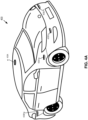
- FIG. 4A illustrates an example autonomous vehicle 400 that may include the LIDAR designs of FIGs. 1B-3 and of the unclaimed example of FIG. 1A .
- the illustrated autonomous vehicle 400 includes an array of sensors configured to capture one or more objects of an external environment of the autonomous vehicle and to generate sensor data related to the captured one or more objects for purposes of controlling the operation of autonomous vehicle 400.
- FIG. 4A shows sensor 433A, 433B, 433C, 433D, and 433E.
- FIG. 4B illustrates a top view of autonomous vehicle 400 including sensors 433F, 433G, 433H, and 4331 in addition to sensors 433A, 433B, 433C, 433D, and 433E.
- FIG. 4C illustrates a block diagram of an example system 499 for autonomous vehicle 400.
- autonomous vehicle 400 may include powertrain 402 including prime mover 404 powered by energy source 406 and capable of providing power to drivetrain 408.
- Autonomous vehicle 400 may further include control system 410 that includes direction control 412, powertrain control 414, and brake control 416.
- Autonomous vehicle 400 may be implemented as any number of different vehicles, including vehicles capable of transporting people and/or cargo and capable of traveling in a variety of different environments. It will be appreciated that the aforementioned components 402 - 416 can vary widely based upon the type of vehicle within which these components are utilized.
- prime mover 404 may include one or more electric motors and/or an internal combustion engine (among others).
- the energy source may include, for example, a fuel system (e.g., providing gasoline, diesel, hydrogen), a battery system, solar panels or other renewable energy source, and/or a fuel cell system.
- Drivetrain 408 may include wheels and/or tires along with a transmission and/or any other mechanical drive components suitable for converting the output of prime mover 404 into vehicular motion, as well as one or more brakes configured to controllably stop or slow the autonomous vehicle 400 and direction or steering components suitable for controlling the trajectory of the autonomous vehicle 400 (e.g., a rack and pinion steering linkage enabling one or more wheels of autonomous vehicle 400 to pivot about a generally vertical axis to vary an angle of the rotational planes of the wheels relative to the longitudinal axis of the vehicle).
- combinations of powertrains and energy sources may be used (e.g., in the case of electric/gas hybrid vehicles).
- multiple electric motors e.g., dedicated to individual wheels or axles) may be used as a prime mover.
- Direction control 412 may include one or more actuators and/or sensors for controlling and receiving feedback from the direction or steering components to enable the autonomous vehicle 400 to follow a desired trajectory.
- Powertrain control 414 may be configured to control the output of powertrain 402, e.g., to control the output power of prime mover 404, to control a gear of a transmission in drivetrain 408, thereby controlling a speed and/or direction of the autonomous vehicle 400.
- Brake control 416 may be configured to control one or more brakes that slow or stop autonomous vehicle 400, e.g., disk or drum brakes coupled to the wheels of the vehicle.
- vehicle control system 420 which may include one or more processors in processing logic 422 and one or more memories 424, with processing logic 422 configured to execute program code (e.g. instructions 426) stored in memory 424.
- Processing logic 422 may include graphics processing unit(s) (GPUs) and/or central processing unit(s) (CPUs), for example.
- Vehicle control system 420 may be configured to control powertrain 402 of autonomous vehicle 400 in response to an output of the optical mixer of a LIDAR pixel such as LIDAR pixel 149 or 150.
- Vehicle control system 420 may be configured to control powertrain 402 of autonomous vehicle 400 in response to outputs from a plurality of LIDAR pixels.
- Vehicle control system 420 may be configured to control powertrain 402 of autonomous vehicle 400 in response to outputs from microcomputer 308 generated based on signals received from FPA system 330.
- Sensors 433A - 433I may include various sensors suitable for collecting data from an autonomous vehicle's surrounding environment for use in controlling the operation of the autonomous vehicle.
- sensors 433A - 433I can include RADAR unit 434, LIDAR unit 436, 3D positioning sensor(s) 438, e.g., a satellite navigation system such as GPS, GLONASS, BeiDou, Galileo, or Compass.
- the LIDAR designs of FIGs. 1A-3 may be included in LIDAR unit 436.
- LIDAR unit 436 may include a plurality of LIDAR sensors that are distributed around autonomous vehicle 400, for example.
- 3D positioning sensor(s) 438 can determine the location of the vehicle on the Earth using satellite signals.
- Sensors 433A - 433I can optionally include one or more ultrasonic sensors, one or more cameras 440, and/or an Inertial Measurement Unit (IMU) 442.
- camera 440 can be a monographic or stereographic camera and can record still and/or video images.
- Camera 440 may include a Complementary Metal-Oxide-Semiconductor (CMOS) image sensor configured to capture images of one or more objects in an external environment of autonomous vehicle 400.
- CMOS Complementary Metal-Oxide-Semiconductor
- IMU 442 can include multiple gyroscopes and accelerometers capable of detecting linear and rotational motion of autonomous vehicle 400 in three directions.
- One or more encoders such as wheel encoders may be used to monitor the rotation of one or more wheels of autonomous vehicle 400.
- the outputs of sensors 433A - 433I may be provided to control subsystems 450, including, localization subsystem 452, trajectory subsystem 456, perception subsystem 454, and control system interface 458.
- Localization subsystem 452 is configured to determine the location and orientation (also sometimes referred to as the "pose") of autonomous vehicle 400 within its surrounding environment, and generally within a particular geographic area. The location of an autonomous vehicle can be compared with the location of an additional vehicle in the same environment as part of generating labeled autonomous vehicle data.
- Perception subsystem 454 may be configured to detect, track, classify, and/or determine objects within the environment surrounding autonomous vehicle 400.
- Trajectory subsystem 456 is configured to generate a trajectory for autonomous vehicle 400 over a particular timeframe given a desired destination as well as the static and moving objects within the environment.
- a machine learning model in accordance with several implementations can be utilized in generating a vehicle trajectory.
- Control system interface 458 is configured to communicate with control system 410 in order to implement the trajectory of the autonomous vehicle 400.
- a machine learning model can be utilized to control an autonomous vehicle to implement the planned trajectory.
- FIG. 4C for vehicle control system 420 is merely exemplary in nature. Individual sensors may be omitted in some implementations. In some implementations, different types of sensors illustrated in FIG. 4C may be used for redundancy and/or for covering different regions in an environment surrounding an autonomous vehicle. In some implementations, different types and/or combinations of control subsystems may be used.
- subsystems 452 - 458 are illustrated as being separate from processing logic 422 and memory 424, it will be appreciated that in some implementations, some or all of the functionality of subsystems 452 - 458 may be implemented with program code such as instructions 426 resident in memory 424 and executed by processing logic 422, and that these subsystems 452 - 458 may in some instances be implemented using the same processor(s) and/or memory. Subsystems in some implementations may be implemented at least in part using various dedicated circuit logic, various processors, various field programmable gate arrays (“FPGA”), various application-specific integrated circuits (“ASIC”), various real time controllers, and the like, as noted above, multiple subsystems may utilize circuitry, processors, sensors, and/or other components. Further, the various components in vehicle control system 420 may be networked in various manners.
- FPGA field programmable gate arrays
- ASIC application-specific integrated circuits
- autonomous vehicle 400 may also include a secondary vehicle control system (not illustrated), which may be used as a redundant or backup control system for autonomous vehicle 400.
- the secondary vehicle control system may be capable of operating autonomous vehicle 400 in response to a particular event.
- the secondary vehicle control system may only have limited functionality in response to the particular event detected in primary vehicle control system 420.
- the secondary vehicle control system may be omitted.
- each processor may be implemented, for example, as a microprocessor and each memory may represent the random access memory (“RAM") devices comprising a main storage, as well as any supplemental levels of memory, e.g., cache memories, non-volatile or backup memories (e.g., programmable or flash memories), or read-only memories.
- RAM random access memory
- each memory may be considered to include memory storage physically located elsewhere in autonomous vehicle 400, e.g., any cache memory in a processor, as well as any storage capacity used as a virtual memory, e.g., as stored on a mass storage device or another computer controller.
- Processing logic 422 illustrated in FIG. 4C may be used to implement additional functionality in autonomous vehicle 400 outside of the purposes of autonomous control, e.g., to control entertainment systems, to operate doors, lights, or convenience features.
- autonomous vehicle 400 may also include one or more mass storage devices, e.g., a removable disk drive, a hard disk drive, a direct access storage device ("DASD”), an optical drive (e.g., a CD drive, a DVD drive), a solid state storage drive (“SSD”), network attached storage, a storage area network, and/or a tape drive, among others.
- DASD direct access storage device
- autonomous vehicle 400 may include a user interface 464 to enable autonomous vehicle 400 to receive a number of inputs from a passenger and generate outputs for the passenger, e.g., one or more displays, touchscreens, voice and/or gesture interfaces, buttons and other tactile controls.
- input from the passenger may be received through another computer or electronic device, e.g., through an app on a mobile device or through a web interface.
- autonomous vehicle 400 may include one or more network interfaces, e.g., network interface 462, suitable for communicating with one or more networks 470 (e.g., a Local Area Network ("LAN”), a wide area network (“WAN”), a wireless network, and/or the Internet, among others) to permit the communication of information with other computers and electronic devices, including, for example, a central service, such as a cloud service, from which autonomous vehicle 400 receives environmental and other data for use in autonomous control thereof.
- networks 470 e.g., a Local Area Network (“LAN”), a wide area network (“WAN”), a wireless network, and/or the Internet, among others
- networks 470 e.g., a Local Area Network (“LAN”), a wide area network (“WAN”), a wireless network, and/or the Internet, among others
- networks 470 e.g., a Local Area Network (“LAN”), a wide area network (“WAN”), a wireless network, and/or the Internet, among others
- a central service such as a
- Processing logic 422 illustrated in FIG. 4C generally operates under the control of an operating system and executes or otherwise relies upon various computer software applications, components, programs, objects, modules, or data structures, as may be described in greater detail below.
- various applications, components, programs, objects, or modules may also execute on one or more processors in another computer coupled to autonomous vehicle 400 through network 470, e.g., in a distributed, cloud-based, or client-server computing environment, whereby the processing required to implement the functions of a computer program may be allocated to multiple computers and/or services over a network.
- Program code typically comprises one or more instructions that are resident at various times in various memory and storage devices, and that, when read and executed by one or more processors, perform the steps necessary to execute steps or elements embodying the various aspects of the invention.
- program code typically comprises one or more instructions that are resident at various times in various memory and storage devices, and that, when read and executed by one or more processors, perform the steps necessary to execute steps or elements embodying the various aspects of the invention.
- implementations have and hereinafter may be described in the context of fully functioning computers and systems, it will be appreciated that the various implementations described herein are capable of being distributed as a program product in a variety of forms, and that implementations can be implemented regardless of the particular type of computer readable media used to actually carry out the distribution.
- Examples of computer readable media include tangible, non-transitory media such as volatile and non-volatile memory devices, floppy and other removable disks, solid state drives, hard disk drives, magnetic tape, and optical disks (e.g., CD-ROMs, DVDs) among others.
- tangible, non-transitory media such as volatile and non-volatile memory devices, floppy and other removable disks, solid state drives, hard disk drives, magnetic tape, and optical disks (e.g., CD-ROMs, DVDs) among others.
- FIG. 4C is not intended to limit implementations disclosed herein. Indeed, those skilled in the art will recognize that other alternative hardware and/or software environments may be used without departing from the scope of implementations disclosed herein.
- processing logic e.g. processing logic 190 or 422 in this disclosure may include one or more processors, microprocessors, multi-core processors, Application-specific integrated circuits (ASIC), and/or Field Programmable Gate Arrays (FPGAs) to execute operations disclosed herein.
- memories are integrated into the processing logic to store instructions to execute operations and/or store data.
- Processing logic may also include analog or digital circuitry to perform the operations in accordance with implementations of the disclosure.
- a “memory” or “memories” described in this disclosure may include one or more volatile or non-volatile memory architectures.
- the “memory” or “memories” may be removable and non-removable media implemented in any method or technology for storage of information such as computer-readable instructions, data structures, program modules, or other data.
- Example memory technologies may include RAM, ROM, EEPROM, flash memory, CD-ROM, digital versatile disks (DVD), high-definition multimedia/data storage disks, or other optical storage, magnetic cassettes, magnetic tape, magnetic disk storage or other magnetic storage devices, or any other non-transmission medium that can be used to store information for access by a computing device.
- a Network may include any network or network system such as, but not limited to, the following: a peer-to-peer network; a Local Area Network (LAN); a Wide Area Network (WAN); a public network, such as the Internet; a private network; a cellular network; a wireless network; a wired network; a wireless and wired combination network; and a satellite network.
- a peer-to-peer network such as, but not limited to, the following: a peer-to-peer network; a Local Area Network (LAN); a Wide Area Network (WAN); a public network, such as the Internet; a private network; a cellular network; a wireless network; a wired network; a wireless and wired combination network; and a satellite network.
- Communication channels may include or be routed through one or more wired or wireless communication utilizing IEEE 802.11 protocols, SPI (Serial Peripheral Interface), I2C (Inter-Integrated Circuit), USB (Universal Serial Port), CAN (Controller Area Network), cellular data protocols (e.g. 3G, 4G, LTE, 5G), optical communication networks, Internet Service Providers (ISPs), a peer-to-peer network, a Local Area Network (LAN), a Wide Area Network (WAN), a public network (e.g. "the Internet”), a private network, a satellite network, or otherwise.
- IEEE 802.11 protocols SPI (Serial Peripheral Interface), I2C (Inter-Integrated Circuit), USB (Universal Serial Port), CAN (Controller Area Network), cellular data protocols (e.g. 3G, 4G, LTE, 5G), optical communication networks, Internet Service Providers (ISPs), a peer-to-peer network, a Local Area Network (LAN), a Wide Area Network (WAN),
- a computing device may include a desktop computer, a laptop computer, a tablet, a phablet, a smartphone, a feature phone, a server computer, or otherwise.
- a server computer may be located remotely in a data center or be stored locally.
- a tangible non-transitory machine-readable storage medium includes any mechanism that provides (i.e., stores) information in a form accessible by a machine (e.g., a computer, network device, personal digital assistant, manufacturing tool, any device with a set of one or more processors, etc.).
- a machine-readable storage medium includes recordable/non-recordable media (e.g., read only memory (ROM), random access memory (RAM), magnetic disk storage media, optical storage media, flash memory devices, etc.).
Landscapes
- Engineering & Computer Science (AREA)
- Physics & Mathematics (AREA)
- General Physics & Mathematics (AREA)
- Radar, Positioning & Navigation (AREA)
- Remote Sensing (AREA)
- Computer Networks & Wireless Communication (AREA)
- Electromagnetism (AREA)
- Nonlinear Science (AREA)
- Optics & Photonics (AREA)
- Automation & Control Theory (AREA)
- Human Computer Interaction (AREA)
- Transportation (AREA)
- Mechanical Engineering (AREA)
- Optical Radar Systems And Details Thereof (AREA)
- Aviation & Aerospace Engineering (AREA)
- Traffic Control Systems (AREA)
Description
- This disclosure relates generally to imaging and in particular to a LIDAR (Light Detection and Ranging).
- Frequency Modulated Continuous Wave (FMCW) LIDAR directly measures range and velocity of an object by directing a frequency modulated, collimated light beam at a target. Both range and velocity information of the target can be derived from FMCW LIDAR signals. Designs and techniques to increase the accuracy of LIDAR signals are desirable.
- The automobile industry is currently developing autonomous features for controlling vehicles under certain circumstances. According to SAE International standard J3016, there are 6 levels of autonomy ranging from Level 0 (no autonomy) up to Level 5 (vehicle capable of operation without operator input in all conditions). A vehicle with autonomous features utilizes sensors to sense the environment that the vehicle navigates through. Acquiring and processing data from the sensors allows the vehicle to navigate through its environment. Autonomous vehicles may include one or more FMCW LIDAR devices for sensing its environment.
US 2020/0150241 A1 relates to a LiDAR system that has a field of view and includes a polarization-based waveguide splitter, which includes a first splitter port, a second splitter port and a common splitter port. A laser is optically coupled to the first splitter port via a single-polarization waveguide. An objective lens ofUS 2020/150241 A1 optically couples each optical emitter of an array of optical emitters to a respective unique portion of the field of view. An optical switching network ofUS 2020/150241 A1 is coupled via respective dual-polarization waveguides between the common splitter port and the array of optical emitters. An optical receiver ofUS 2020/0150241 A1 is optically coupled to the second splitter port via a dual-polarization waveguide and is configured to receive light reflected from the field of view. A controller ofUS 2020/0150241 A1 , coupled to the optical switching network, is configured to cause the optical switching network to route light from the laser to a sequence of the optical emitters according to a temporal pattern.
Caspers J.N., et al.: "Active polarization independent coupling to silicon photonics circuit", Proc. SPIE 9133, Silicon Photonics and Photonic Integrated Circuits IV, 91330G, 1 May 2014 (https://doi.org/10.1117/12.2049713) discuss the ability to couple an arbitrary polarization state from a fiber to the TE-mode of a single waveguide in an integrated silicon photonics circuit with an extinction ratio larger than 31 dB, measured between the output ports of the integrated photonic circuit. To achieve this a 2D- grating coupler and a Mach-Zehnder Interferometer were combined in that article.
US 10 495 794 B2 US 10 495 794 B2 US 10 495 794 B2
US 2014/0299743 A1 relates to a coherent N to one wave combiner having N≥2 inputs and a single output. The apparatus ofUS 2014/0299743 A1 comprises a coherent wave superposition network that is linear, reciprocal and lossless, and which includes one or more series-connected 2×2 wave splitters configured such that the contribution of each of the N inputs to the output is adjustable in both amplitude and relative phase; wherein the coherent wave superposition network provides N-1 control ports at which waves not coupled to the output are emitted; and N-1 detectors disposed at the control ports; wherein amplitude splits and phase shifts of the coherent wave superposition network ofUS 2014/0299743 A1 are determined in operation by adjusting them in sequence to sequentially null signals from the N-1 detectors. - According to an aspect of the present invention, there is provided a light detection and ranging (LIDAR) system as set out in independent claim 1. According to another aspect of the present invention, there is provided a coherent LIDAR pixel as set out in independent claim 8. Other embodiments are described in the dependent claims.
- Non-limiting and non-exhaustive implementations of the invention are described with reference to the following figures, wherein like reference numerals refer to like parts throughout the various views unless otherwise specified.
-
FIG. 1A illustrates an example LIDAR device not according to the invention including a LIDAR pixel having active polarization control not according to the invention. -
FIG. 1B illustrates an example LIDAR pixel including a first phase shifter and a second phase shifter for active polarization control, in accordance with implementations of the disclosure. -
FIG. 2 demonstrates how more than one coherent pixel with active polarization control can be combined into a focal plane array (FPA), in accordance with implementations of the disclosure. -
FIG. 3 demonstrates how an array of coherent pixels with active polarization control can be used in an FMCW LIDAR system, in accordance with implementations of the disclosure. -
FIG. 4A illustrates an autonomous vehicle including an array of example sensors, in accordance with implementations of the disclosure. -
FIG. 4B illustrates a top view of an autonomous vehicle including an array of example sensors, in accordance with implementations of the disclosure. -
FIG. 4C illustrates an example vehicle control system including sensors, a drivetrain, and a control system, in accordance with implementations of the disclosure. - Implementations of active polarization control for LIDAR pixels are described herein. In the following description, numerous specific details are set forth to provide a thorough understanding of the implementations.
- Throughout this specification, several terms of art are used. These terms are to take on their ordinary meaning in the art from which they come, unless specifically defined herein or the context of their use would clearly suggest otherwise. For the purposes of this disclosure, the term "autonomous vehicle" includes vehicles with autonomous features at any level of autonomy of the SAE International standard J3016.
- In aspects of this disclosure, visible light may be defined as having a wavelength range of approximately 380 nm - 700 nm. Non-visible light may be defined as light having wavelengths that are outside the visible light range, such as ultraviolet light and infrared light. Infrared light having a wavelength range of approximately 700 nm - 1 mm includes near-infrared light. In aspects of this disclosure, near-infrared light may be defined as having a wavelength range of approximately 700 nm - 1.6 µm.
- In aspects of this disclosure, the term "transparent" may be defined as having greater than 90% transmission of light. In some aspects, the term "transparent" may be defined as a material having greater than 90% transmission of visible light.
- Frequency Modulated Continuous Wave (FMCW) LIDAR directly measures range and velocity of an object by directing a frequency modulated, collimated light beam at the object. The light that is reflected from the object is combined with a tapped version of the beam. The frequency of the resulting beat tone is proportional to the distance of the object from the LIDAR system once corrected for the doppler shift that requires a second measurement. The two measurements, which may or may not be performed at the same time, provide both range and velocity information.
- FMCW LIDAR can take advantage of integrated photonics for improved manufacturability and performance. Integrated photonic systems typically manipulate single optical modes using micron-scale waveguiding devices.
- Coherent light generated by FMCW LIDAR reflecting off of a diffuse surface produces a speckle pattern, which is characterized by a random intensity and phase profile in the reflected optical field. This speckle field reduces the amount of power which can couple back into a single-mode optical system. As an FMCW LIDAR beam is scanned across a diffuse surface, the reflected speckle field has time-varying behavior which leads to a broadened signal spectrum.
- Implementations of the disclosure include one or more coherent pixels with active polarization control. Light in the coherent pixel may be evenly split into two "arms" and then the amplitude and relative phase of the two arms of the pixel can be arbitrarily manipulated. The light in the two arms may be passed into a dual-polarization optical coupler. This coupler may couple the light into free space with two orthogonal polarizations.
- By controlling the amplitude and phase of the two arms of the coherent pixel, the output polarization of light can be arbitrarily selected. Alternatively, by controlling the amplitude and phase of the two arms of the coherent pixel, it can be made arbitrarily sensitive to receiving a particular polarization of light.
-
FIG. 1A illustrates anexample LIDAR device 199 not according to the invention including aLIDAR pixel 150 having active polarization control not according to the invention.LIDAR pixel 150 inFIG. 1A includes a1x2 splitter 152, anoptical mixer 159, agrating coupler 161, and apolarization controller 180.Polarization controller 180 includes a2x2 splitter 156 and aphase shifter 157.Polarization controller 180 includes atop arm 162 and abottom arm 160. -
Light 151 enteringLIDAR pixel 150 can be split by a splitter (e.g. 1x2 splitter 152).Light 151 may be infrared laser light generated by a laser (e.g. a continuous wave laser). In some implementations, the laser light may be collimated. The split ratio ofsplitter 152 may be selected as desired for the FMCW LIDAR system. A portion (e.g. between 70% and 99%) of this split light propagates through aninterconnect 153 to2x2 splitter 156. The remaining light (e.g. between 1% and 30%) leaving the bottom output port of1x2 splitter 152 propagates through aninterconnect 154 tooptical mixer 159. In some implementations,input light 151 and1x2 splitter 152 may be replaced with two independent light sources. - In the transmit direction,
polarization controller 180 is configured to receive a first portion of the split light that is split by1x2 splitter 152. The first portion of the split light propagates topolarization controller 180 by way ofinterconnect 153. Light entering the2x2 splitter 156 is split between its two output ports. The top output port of2x2 splitter 156 starts the "top arm" 162 ofpolarization controller 180 and the bottom port of2x2 splitter 156 starts the "bottom arm" 160 ofpolarization controller 180. In some implementations, the split ratio between the top port and the bottom port of2x2 splitter 156 is 50:50, however other split ratios may be selected if desired. Light in thetop arm 162 passes throughphase shifter 157 which can be controlled in order to arbitrarily set the phase of the light intop arm 162 relative tobottom arm 160. -
Phase shifter 157 sets a phase of top-light propagating intop arm 162 relative to bottom-light propagating inbottom arm 160. InFIG. 1A , processinglogic 190 is configured to controlphase shifter 157. Light intop arm 162 propagates into atop port 168 ofgrating coupler 161 while light in thebottom arm 160 propagates into abottom port 169 ofgrating coupler 161.Grating coupler 161 may be a dual-polarization grating coupler configured to outcouple a first polarization orientation of light and a second polarization orientation of light that is orthogonal to the first polarization orientation of light.Grating coupler 161 couples light fromtop port 168 into a first polarization beam (e.g. "TE" polarized beam) and couples light frombottom port 169 into a second polarization beam (e.g. "TM" polarized beam), in some implementations. These two orthogonal beams superimpose to form an output beam oflight 193 with arbitrary polarization which is determined by the state ofphase shifter 157. Thus, gratingcoupler 161 is configured to output an output beam oflight 193 in response to receiving top-light propagating intop arm 162 and bottom-light propagating inbottom arm 160. - In the illustrated implementation,
grating coupler 161 is presented as the "antenna." - In the receive direction, arbitrarily-polarized
light 194 entersgrating coupler 161. Light with the first polarization couples intotop arm 162 and passes throughphase shifter 157. Light with the second polarization couples intobottom arm 160. The light in both arms then passes through2x2 splitter 156.Phase shifter 157 can be controlled such that a maximum amount of light couples into the bottom port of2x2 splitter 156 which connects to interconnect 163. The light ininterconnect 163 is fed intooptical mixer 159, which combines it with the light ininterconnect 154. The light ininterconnect 154 is the remaining light from the first portion of light propagating ininterconnect 153. Thus,optical mixer 159 is configured to output anoutput signal 164 in response to receiving the remaining portion of the split light and the reflected beam 194 (propagating throughbottom arm 160 and 2x2 splitter 156).Optical mixer 159 converts these mixed optical signals (light ininterconnects 163 and interconnects 154) to the electrical domain, producing one or more output signals 164. For example,output signal 164 may be an electronic signal such as a "beat signal." - As described above,
phase shifter 157 sets a phase of top-light propagating intop arm 162 relative to bottom-light propagating inbottom arm 160. In the illustrated implementation ofFIG. 1A , processinglogic 190 is configured to controlphase shifter 157 in response to receiving beat signal 164 fromLIDAR pixel 150. In some implementations,processing logic 190 is configured to drivephase shifter 157 to different phase values and then select the phase value that generates thebeat signal 164 with the highest amplitude and drive that selected phase value ontophase shifter 157 to increase or even maximize a signal level of thebeat signal 164. As different target surfaces reflect different polarization orientations,processing logic 190 may drivephase shifter 157 to different phase values that increase an amplitude ofbeat signal 164 due to the different polarizations of light reflected by different target surfaces. In some implementations,processing logic 190 receives beatsignals 164 from a plurality ofLIDAR pixels 150 and generates animage 191 from the plurality of beat signals. -
FIG. 1B illustrates anexample LIDAR pixel 149 according to the invention including afirst phase shifter 107 and asecond phase shifter 109 for active polarization control, in accordance with implementations of the disclosure.Light 101 entering thecoherent pixel 149 is split by a splitter (e.g. 1x2 splitter 102). The split ratio of this splitter may be selected as desired for the FMCW LIDAR system. A portion of this split light (e.g. between 70% and 99%) propagates through aninterconnect 103 to a2x2 splitter 105. The remaining light (e.g. between 1% and 30%) leaving the bottom output port of the 1x2 splitter propagates through aninterconnect 104 to anoptical mixer 106. In some implementations not according to the invention,input light 101 and1x2 splitter 102 may be replaced with two independent light sources. - In the transmit direction, light entering the
2x2 splitter 105 is split between its two output ports (which constitute the first stage of thepolarization controller 130 with a "top arm" and "bottom arm"). The first stage includesfirst 2x2 splitter 105 andfirst phase shifter 107. In an implementation ofcoherent pixel 149, the split ratio is 50:50, however other split ratios may be selected if desired. Light in the top arm passes through afirst phase shifter 107 which can be controlled in order to arbitrarily set the phase of the light in the top arm relative to the bottom arm. - The light in the top and bottom arms enter a second 2x2 splitter 108 (the second stage of polarization controller 130). The second stage includes
second 2x2 splitter 108 andsecond phase shifter 109. Depending on the phase shift of the two arms, the amplitude of light leaving the top and bottom ports ofsplitter 108 can be controlled. Light in the top arm of this second stage passes throughsecond phase shifter 109 which can be controlled to arbitrarily set the relative phase of the top and bottom arms of the second stage. Light in the top arm propagates into thetop port 118 of the dual-polarization grating coupler 111 while light in thebottom arm 110 propagates into thebottom port 119 of the dual-polarization grating coupler 111.Top port 118 is optically coupled tosecond phase shifter 109. Thegrating coupler 111 couples light from thetop port 118 into a first polarized beam and couples light from thebottom port 119 into a second orthogonal polarized beam. These two orthogonal beams superimpose to form a beam oflight 143 with arbitrary polarization which is determined by the state of the twophase shifters - In the illustrated implementation, dual-
polarization grating coupler 111 is presented as the "antenna." - In the receive direction, arbitrarily-polarized light 144 enters dual-
polarization grating coupler 111. Light with the first polarization couples into thetop arm 112 of the second stage and passes throughsecond phase shifter 109. Light with the second polarization couples into thebottom arm 110 of the second stage. The light in both arms then passes through the2x2 splitter 108, entering the first stage. Light in the top arm of the first stage passes throughfirst phase shifter 107. Light in both arms of the first stage pass through the2x2 splitter 105.First phase shifter 107 andsecond phase shifter 109 can be controlled such that a maximum amount of light couples into the bottom port of2x2 splitter 105 which connects to interconnect 113. The light in 113 is fed into theoptical mixer 106, which combines it with the light ininterconnect 104.Optical mixer 106 converts this mixed optical signal to the electrical domain, producing one or more output signals 114. -
FIG. 2 demonstrates how more than onecoherent pixel 203 with active polarization control can be combined into a focal plane array (FPA) 201.Coherent pixel 203 may be implemented with the designs ofLIDAR pixel 149 according to the invention orLIDAR pixel 150 not according to the invention. Multipleoptical channels 202 enter the array. These can be discrete parallel channels or switched between the pixels using an optical circuit. In some implementations, the same continuous wave (CW) infrared laser provides laser light for each of theoptical channels 202. Waveguides, optical fibers, micro-optical components, optical amplifiers and/or photonic circuits may be implemented so that each ofchannels 202 receives a portion of the laser light from the CW infrared laser. Light enters each coherent pixel (e.g. 203) which manipulates, transmits, and receives the light witharbitrary polarizations 204 as previously described. The received light is converted into an array of outputelectrical signals 205. Image processing may be performed on the array of outputelectrical signals 205 to generate an image of an environment imaged byFPA 201. -
FIG. 3 demonstrates how the array of coherent pixels with active polarization control can be used in anFMCW LIDAR system 399, in accordance with implementations of the disclosure. InFIG. 3 , alens 300 takes input from active polarization controlledcoherent pixel array 301. Active polarization controlledcoherent pixel array 301 may includeFPA 201 in some implementations.Lens 300 also receives output beams with a range ofangles 306. The pixels in the active polarization controlledcoherent pixel array 301 are controlled by anFPA driver module 304. An individual pixel in the array may be turned on to emit and receive light or multiple simultaneous pixels in the array may be turned on to simultaneously emit or receive light. Light emitted by the active polarization controlledcoherent pixel array 301 is produced by a laser array with Qparallel channels 303. This laser array may be integrated directly with the active polarization controlledcoherent pixel array 301 or may be a separate module packaged alongside active polarization controlledcoherent pixel array 301. The laser array is controlled by alaser driver module 305, which receives control signals from aLIDAR processing engine 302 via a digital to analog converter (DAC) 307.LIDAR processing engine 302 also controlsFPA driver 304 and sends and receives data from active polarization controlledcoherent pixel array 301. -
LIDAR processing engine 302 includes amicrocomputer 308.Microcomputer 308 may process data coming fromFPA system 330 and send control signals toFPA system 330 viaFPA driver 304 andlaser controller 305. Signals are received by N-channel receiver 309 ofLIDAR processing engine 302. These incoming signals are digitized using a set of M-channel analog to digital converters (ADC) 310 andmicrocomputer 308 is configured to receive the digitized version of the signals. -
FIG. 4A illustrates an exampleautonomous vehicle 400 that may include the LIDAR designs ofFIGs. 1B-3 and of the unclaimed example ofFIG. 1A . The illustratedautonomous vehicle 400 includes an array of sensors configured to capture one or more objects of an external environment of the autonomous vehicle and to generate sensor data related to the captured one or more objects for purposes of controlling the operation ofautonomous vehicle 400.FIG. 4A showssensor FIG. 4B illustrates a top view ofautonomous vehicle 400 includingsensors sensors sensors FIGs. 1A-3 .FIG. 4C illustrates a block diagram of anexample system 499 forautonomous vehicle 400. For example,autonomous vehicle 400 may includepowertrain 402 includingprime mover 404 powered byenergy source 406 and capable of providing power todrivetrain 408.Autonomous vehicle 400 may further includecontrol system 410 that includesdirection control 412,powertrain control 414, andbrake control 416.Autonomous vehicle 400 may be implemented as any number of different vehicles, including vehicles capable of transporting people and/or cargo and capable of traveling in a variety of different environments. It will be appreciated that the aforementioned components 402 - 416 can vary widely based upon the type of vehicle within which these components are utilized. - The implementations discussed hereinafter, for example, will focus on a wheeled land vehicle such as a car, van, truck, or bus. In such implementations,
prime mover 404 may include one or more electric motors and/or an internal combustion engine (among others). The energy source may include, for example, a fuel system (e.g., providing gasoline, diesel, hydrogen), a battery system, solar panels or other renewable energy source, and/or a fuel cell system.Drivetrain 408 may include wheels and/or tires along with a transmission and/or any other mechanical drive components suitable for converting the output ofprime mover 404 into vehicular motion, as well as one or more brakes configured to controllably stop or slow theautonomous vehicle 400 and direction or steering components suitable for controlling the trajectory of the autonomous vehicle 400 (e.g., a rack and pinion steering linkage enabling one or more wheels ofautonomous vehicle 400 to pivot about a generally vertical axis to vary an angle of the rotational planes of the wheels relative to the longitudinal axis of the vehicle). In some implementations, combinations of powertrains and energy sources may be used (e.g., in the case of electric/gas hybrid vehicles). In some implementations, multiple electric motors (e.g., dedicated to individual wheels or axles) may be used as a prime mover. -
Direction control 412 may include one or more actuators and/or sensors for controlling and receiving feedback from the direction or steering components to enable theautonomous vehicle 400 to follow a desired trajectory.Powertrain control 414 may be configured to control the output ofpowertrain 402, e.g., to control the output power ofprime mover 404, to control a gear of a transmission indrivetrain 408, thereby controlling a speed and/or direction of theautonomous vehicle 400.Brake control 416 may be configured to control one or more brakes that slow or stopautonomous vehicle 400, e.g., disk or drum brakes coupled to the wheels of the vehicle. - Other vehicle types, including but not limited to off-road vehicles, all-terrain or tracked vehicles, or construction equipment will necessarily utilize different powertrains, drivetrains, energy sources, direction controls, powertrain controls and brake controls, as will be appreciated by those of ordinary skill having the benefit of the instant disclosure. Moreover, in some implementations some of the components can be combined, e.g., where directional control of a vehicle is primarily handled by varying an output of one or more prime movers. Therefore, implementations disclosed herein are not limited to the particular application of the herein-described techniques in an autonomous wheeled land vehicle.
- In the illustrated implementation, autonomous control over
autonomous vehicle 400 is implemented invehicle control system 420, which may include one or more processors in processing logic 422 and one ormore memories 424, with processing logic 422 configured to execute program code (e.g. instructions 426) stored inmemory 424. Processing logic 422 may include graphics processing unit(s) (GPUs) and/or central processing unit(s) (CPUs), for example.Vehicle control system 420 may be configured to controlpowertrain 402 ofautonomous vehicle 400 in response to an output of the optical mixer of a LIDAR pixel such asLIDAR pixel Vehicle control system 420 may be configured to controlpowertrain 402 ofautonomous vehicle 400 in response to outputs from a plurality of LIDAR pixels.Vehicle control system 420 may be configured to controlpowertrain 402 ofautonomous vehicle 400 in response to outputs frommicrocomputer 308 generated based on signals received fromFPA system 330. -
Sensors 433A - 433I may include various sensors suitable for collecting data from an autonomous vehicle's surrounding environment for use in controlling the operation of the autonomous vehicle. For example,sensors 433A - 433I can includeRADAR unit 434,LIDAR unit FIGs. 1A-3 may be included inLIDAR unit 436.LIDAR unit 436 may include a plurality of LIDAR sensors that are distributed aroundautonomous vehicle 400, for example. In some implementations, 3D positioning sensor(s) 438 can determine the location of the vehicle on the Earth using satellite signals.Sensors 433A - 433I can optionally include one or more ultrasonic sensors, one ormore cameras 440, and/or an Inertial Measurement Unit (IMU) 442. In some implementations,camera 440 can be a monographic or stereographic camera and can record still and/or video images.Camera 440 may include a Complementary Metal-Oxide-Semiconductor (CMOS) image sensor configured to capture images of one or more objects in an external environment ofautonomous vehicle 400.IMU 442 can include multiple gyroscopes and accelerometers capable of detecting linear and rotational motion ofautonomous vehicle 400 in three directions. One or more encoders (not illustrated) such as wheel encoders may be used to monitor the rotation of one or more wheels ofautonomous vehicle 400. - The outputs of
sensors 433A - 433I may be provided to controlsubsystems 450, including,localization subsystem 452,trajectory subsystem 456,perception subsystem 454, andcontrol system interface 458.Localization subsystem 452 is configured to determine the location and orientation (also sometimes referred to as the "pose") ofautonomous vehicle 400 within its surrounding environment, and generally within a particular geographic area. The location of an autonomous vehicle can be compared with the location of an additional vehicle in the same environment as part of generating labeled autonomous vehicle data.Perception subsystem 454 may be configured to detect, track, classify, and/or determine objects within the environment surroundingautonomous vehicle 400.Trajectory subsystem 456 is configured to generate a trajectory forautonomous vehicle 400 over a particular timeframe given a desired destination as well as the static and moving objects within the environment. A machine learning model in accordance with several implementations can be utilized in generating a vehicle trajectory.Control system interface 458 is configured to communicate withcontrol system 410 in order to implement the trajectory of theautonomous vehicle 400. In some implementations, a machine learning model can be utilized to control an autonomous vehicle to implement the planned trajectory. - It will be appreciated that the collection of components illustrated in
FIG. 4C forvehicle control system 420 is merely exemplary in nature. Individual sensors may be omitted in some implementations. In some implementations, different types of sensors illustrated inFIG. 4C may be used for redundancy and/or for covering different regions in an environment surrounding an autonomous vehicle. In some implementations, different types and/or combinations of control subsystems may be used. Further, while subsystems 452 - 458 are illustrated as being separate from processing logic 422 andmemory 424, it will be appreciated that in some implementations, some or all of the functionality of subsystems 452 - 458 may be implemented with program code such asinstructions 426 resident inmemory 424 and executed by processing logic 422, and that these subsystems 452 - 458 may in some instances be implemented using the same processor(s) and/or memory. Subsystems in some implementations may be implemented at least in part using various dedicated circuit logic, various processors, various field programmable gate arrays ("FPGA"), various application-specific integrated circuits ("ASIC"), various real time controllers, and the like, as noted above, multiple subsystems may utilize circuitry, processors, sensors, and/or other components. Further, the various components invehicle control system 420 may be networked in various manners. - In some implementations,
autonomous vehicle 400 may also include a secondary vehicle control system (not illustrated), which may be used as a redundant or backup control system forautonomous vehicle 400. In some implementations, the secondary vehicle control system may be capable of operatingautonomous vehicle 400 in response to a particular event. The secondary vehicle control system may only have limited functionality in response to the particular event detected in primaryvehicle control system 420. In still other implementations, the secondary vehicle control system may be omitted. - In some implementations, different architectures, including various combinations of software, hardware, circuit logic, sensors, and networks may be used to implement the various components illustrated in
FIG. 4C . Each processor may be implemented, for example, as a microprocessor and each memory may represent the random access memory ("RAM") devices comprising a main storage, as well as any supplemental levels of memory, e.g., cache memories, non-volatile or backup memories (e.g., programmable or flash memories), or read-only memories. In addition, each memory may be considered to include memory storage physically located elsewhere inautonomous vehicle 400, e.g., any cache memory in a processor, as well as any storage capacity used as a virtual memory, e.g., as stored on a mass storage device or another computer controller. Processing logic 422 illustrated inFIG. 4C , or entirely separate processing logic, may be used to implement additional functionality inautonomous vehicle 400 outside of the purposes of autonomous control, e.g., to control entertainment systems, to operate doors, lights, or convenience features. - In addition, for additional storage,
autonomous vehicle 400 may also include one or more mass storage devices, e.g., a removable disk drive, a hard disk drive, a direct access storage device ("DASD"), an optical drive (e.g., a CD drive, a DVD drive), a solid state storage drive ("SSD"), network attached storage, a storage area network, and/or a tape drive, among others. Furthermore,autonomous vehicle 400 may include a user interface 464 to enableautonomous vehicle 400 to receive a number of inputs from a passenger and generate outputs for the passenger, e.g., one or more displays, touchscreens, voice and/or gesture interfaces, buttons and other tactile controls. In some implementations, input from the passenger may be received through another computer or electronic device, e.g., through an app on a mobile device or through a web interface. - In some implementations,
autonomous vehicle 400 may include one or more network interfaces, e.g.,network interface 462, suitable for communicating with one or more networks 470 (e.g., a Local Area Network ("LAN"), a wide area network ("WAN"), a wireless network, and/or the Internet, among others) to permit the communication of information with other computers and electronic devices, including, for example, a central service, such as a cloud service, from whichautonomous vehicle 400 receives environmental and other data for use in autonomous control thereof. In some implementations, data collected by one ormore sensors 433A - 433I can be uploaded tocomputing system 472 throughnetwork 470 for additional processing. In such implementations, a time stamp can be associated with each instance of vehicle data prior to uploading. - Processing logic 422 illustrated in
FIG. 4C , as well as various additional controllers and subsystems disclosed herein, generally operates under the control of an operating system and executes or otherwise relies upon various computer software applications, components, programs, objects, modules, or data structures, as may be described in greater detail below. Moreover, various applications, components, programs, objects, or modules may also execute on one or more processors in another computer coupled toautonomous vehicle 400 throughnetwork 470, e.g., in a distributed, cloud-based, or client-server computing environment, whereby the processing required to implement the functions of a computer program may be allocated to multiple computers and/or services over a network. - Routines executed to implement the various implementations described herein, whether implemented as part of an operating system or a specific application, component, program, object, module or sequence of instructions, or even a subset thereof, will be referred to herein as "program code." Program code typically comprises one or more instructions that are resident at various times in various memory and storage devices, and that, when read and executed by one or more processors, perform the steps necessary to execute steps or elements embodying the various aspects of the invention. Moreover, while implementations have and hereinafter may be described in the context of fully functioning computers and systems, it will be appreciated that the various implementations described herein are capable of being distributed as a program product in a variety of forms, and that implementations can be implemented regardless of the particular type of computer readable media used to actually carry out the distribution. Examples of computer readable media include tangible, non-transitory media such as volatile and non-volatile memory devices, floppy and other removable disks, solid state drives, hard disk drives, magnetic tape, and optical disks (e.g., CD-ROMs, DVDs) among others.
- In addition, various program code described hereinafter may be identified based upon the application within which it is implemented in a specific implementation. However, it should be appreciated that any particular program nomenclature that follows is used merely for convenience, and thus the invention should not be limited to use solely in any specific application identified and/or implied by such nomenclature. Furthermore, given the typically endless number of manners in which computer programs may be organized into routines, procedures, methods, modules, objects, and the like, as well as the various manners in which program functionality may be allocated among various software layers that are resident within a typical computer (e.g., operating systems, libraries, API's, applications, applets), it should be appreciated that the invention is not limited to the specific organization and allocation of program functionality described herein.
- Those skilled in the art, having the benefit of the present disclosure, will recognize that the exemplary environment illustrated in
FIG. 4C is not intended to limit implementations disclosed herein. Indeed, those skilled in the art will recognize that other alternative hardware and/or software environments may be used without departing from the scope of implementations disclosed herein. - The term "processing logic" (
e.g. processing logic 190 or 422) in this disclosure may include one or more processors, microprocessors, multi-core processors, Application-specific integrated circuits (ASIC), and/or Field Programmable Gate Arrays (FPGAs) to execute operations disclosed herein. In some implementations, memories (not illustrated) are integrated into the processing logic to store instructions to execute operations and/or store data. Processing logic may also include analog or digital circuitry to perform the operations in accordance with implementations of the disclosure. - A "memory" or "memories" described in this disclosure may include one or more volatile or non-volatile memory architectures. The "memory" or "memories" may be removable and non-removable media implemented in any method or technology for storage of information such as computer-readable instructions, data structures, program modules, or other data. Example memory technologies may include RAM, ROM, EEPROM, flash memory, CD-ROM, digital versatile disks (DVD), high-definition multimedia/data storage disks, or other optical storage, magnetic cassettes, magnetic tape, magnetic disk storage or other magnetic storage devices, or any other non-transmission medium that can be used to store information for access by a computing device.
- A Network may include any network or network system such as, but not limited to, the following: a peer-to-peer network; a Local Area Network (LAN); a Wide Area Network (WAN); a public network, such as the Internet; a private network; a cellular network; a wireless network; a wired network; a wireless and wired combination network; and a satellite network.
- Communication channels may include or be routed through one or more wired or wireless communication utilizing IEEE 802.11 protocols, SPI (Serial Peripheral Interface), I2C (Inter-Integrated Circuit), USB (Universal Serial Port), CAN (Controller Area Network), cellular data protocols (e.g. 3G, 4G, LTE, 5G), optical communication networks, Internet Service Providers (ISPs), a peer-to-peer network, a Local Area Network (LAN), a Wide Area Network (WAN), a public network (e.g. "the Internet"), a private network, a satellite network, or otherwise.
- A computing device may include a desktop computer, a laptop computer, a tablet, a phablet, a smartphone, a feature phone, a server computer, or otherwise. A server computer may be located remotely in a data center or be stored locally.
- The processes explained above are described in terms of computer software and hardware. The techniques described may constitute machine-executable instructions embodied within a tangible or non-transitory machine (e.g., computer) readable storage medium, that when executed by a machine will cause the machine to perform the operations described. Additionally, the processes may be embodied within hardware, such as an application specific integrated circuit ("ASIC") or otherwise.
- A tangible non-transitory machine-readable storage medium includes any mechanism that provides (i.e., stores) information in a form accessible by a machine (e.g., a computer, network device, personal digital assistant, manufacturing tool, any device with a set of one or more processors, etc.). For example, a machine-readable storage medium includes recordable/non-recordable media (e.g., read only memory (ROM), random access memory (RAM), magnetic disk storage media, optical storage media, flash memory devices, etc.).
Claims (9)
- A light detection and ranging, LIDAR, system (399) comprising:a laser that is configured to generate light;a splitter (102) that is configured to split the light (101) into a plurality of split lights;a polarization controller (130) configured to receive a first split light of the plurality of split lights,wherein the polarization controller includes a first stage including a first 2x2 splitter (105) and a first phase shifter (107) and a second stage including a second 2x2 splitter (108) and a second phase shifter (109), the polarization controller including a first arm (112) and a second arm (110), wherein the first arm includes the first phase shifter (107) and the second phase shifter (109) that are configured to be controlled to set a phase of light that passes through the first arm relative to the second arm,wherein the first 2x2 splitter (105) is configured to split the first split light entering the first 2x2 splitter between its two output ports into the first and second arms of the first stage, wherein light in the first arm of the first stage passes through the first phase shifter (107),wherein light in the first and second arms of the first stage enters the second 2x2 splitter (108) and outputs into the first and second arms of the second stage, wherein light in the first arm of the second stage passes through the second phase shifter (109); anda dual-polarization grating coupler (111) including a first port (118) to receive light from the first arm (112) and a second port (119) configured to receive light from the second arm (110), wherein the dual-polarization grating coupler is configured to couple the light from the first port (118) into a first beam having a first polarization orientation, and wherein the dual-polarization grating coupler is configured to couple the light from the second arm into a second beam with a second polarization orientation,wherein the first port (118) of the dual-polarization grating coupler (111) is optically coupled to the second phase shifter (109).
- The LIDAR system of claim 1 further comprising:an optical mixer (106) configured to receive a second light of the plurality of split lights, wherein the dual-polarization grating coupler is configured to couple reflected light having the first polarization orientation into the first arm and configured to couple the reflected light having the second polarization orientation into the second arm,and wherein the optical mixer is configured to output an output signal in response to the reflected light and the second light.
- The LIDAR system of claim 2, wherein the splitter (102) is configured to provide the second light to the optical mixer (106).
- The LIDAR system of claim 2, wherein the first 2x2 splitter (105) connects to an interconnect (113) that feeds into the optical mixer.
- The LIDAR system of claim 2, wherein the reflected light is reflected from targets.
- The LIDAR system of claim 1, wherein the second beam with the second polarization orientation is orthogonal to the first polarization orientation.
- The LIDAR system of claim 6, wherein the first and second beams superimpose to form a beam of light (143) with an arbitrary polarization.
- A coherent LIDAR pixel (149) including:a splitter (102) that is configured to split light (101) entering the coherent LIDAR pixel into a plurality of split lights;a polarization controller (130) configured to receive a first split light of the plurality of split lights,wherein the polarization controller includes a first stage including a first 2x2 splitter (105) and a first phase shifter (107) and a second stage including a second 2x2 splitter (108) and a second phase shifter (109), the polarization controller including a first arm (112) and a second arm (110), wherein the first arm includes the first phase shifter (107) and the second phase shifter (109) that are configured to be controlled to set a phase of light that passes through the first arm relative to the second arm,wherein the first 2x2 splitter (105) is configured to split the first split light entering the first 2x2 splitter between its two output ports into the first and second arms of the first stage, wherein light in the first arm of the first stage passes through the first phase shifter (107),wherein light in the first and second arms of the first stage enters the second 2x2 splitter (108) and outputs into the first and second arms of the second stage, wherein light in the first arm of the second stage passes through the second phase shifter (109);a dual-polarization grating coupler (111) including a first port (118) to receive light from the first arm (112) and a second port (119) configured to receive light from the second arm (110), wherein the dual-polarization grating coupler is configured to couple the light from the first port (118) into a first beam having a first polarization orientation, and wherein the dual-polarization grating coupler is configured to couple the light from the second arm into a second beam with a second polarization orientation,wherein the first port (118) of the dual-polarization grating coupler (111) is optically coupled to the second phase shifter (109); andan optical mixer (106) configured to receive a second light of the plurality of split lights, wherein the dual-polarization grating coupler is configured to couple reflected light having the first polarization orientation into the first arm and configured to couple the reflected light having the second polarization orientation into the second arm,and wherein the optical mixer is configured to output an output signal in response to the reflected light and the second light.
- An autonomous vehicle (400) comprising a LIDAR system according to claim 1.
Priority Applications (1)
| Application Number | Priority Date | Filing Date | Title |
|---|---|---|---|
| EP24219557.6A EP4498149A3 (en) | 2020-06-12 | 2021-06-11 | Lidar pixel with active polarization control |
Applications Claiming Priority (3)
| Application Number | Priority Date | Filing Date | Title |
|---|---|---|---|
| US202063038452P | 2020-06-12 | 2020-06-12 | |
| US17/344,386 US11428785B2 (en) | 2020-06-12 | 2021-06-10 | Lidar pixel with active polarization control |
| PCT/US2021/037006 WO2021252893A1 (en) | 2020-06-12 | 2021-06-11 | Lidar pixel with active polarization control |
Related Child Applications (1)
| Application Number | Title | Priority Date | Filing Date |
|---|---|---|---|
| EP24219557.6A Division EP4498149A3 (en) | 2020-06-12 | 2021-06-11 | Lidar pixel with active polarization control |
Publications (2)
| Publication Number | Publication Date |
|---|---|
| EP4133303A1 EP4133303A1 (en) | 2023-02-15 |
| EP4133303B1 true EP4133303B1 (en) | 2024-12-18 |
Family
ID=78826516
Family Applications (2)
| Application Number | Title | Priority Date | Filing Date |
|---|---|---|---|
| EP21737311.7A Active EP4133303B1 (en) | 2020-06-12 | 2021-06-11 | Lidar pixel with active polarization control |
| EP24219557.6A Pending EP4498149A3 (en) | 2020-06-12 | 2021-06-11 | Lidar pixel with active polarization control |
Family Applications After (1)
| Application Number | Title | Priority Date | Filing Date |
|---|---|---|---|
| EP24219557.6A Pending EP4498149A3 (en) | 2020-06-12 | 2021-06-11 | Lidar pixel with active polarization control |
Country Status (8)
| Country | Link |
|---|---|
| US (2) | US11428785B2 (en) |
| EP (2) | EP4133303B1 (en) |
| JP (2) | JP7349035B2 (en) |
| KR (2) | KR102717684B1 (en) |
| CN (2) | CN117991230A (en) |
| AU (1) | AU2021287986B2 (en) |
| CA (2) | CA3181747A1 (en) |
| WO (1) | WO2021252893A1 (en) |
Families Citing this family (4)
| Publication number | Priority date | Publication date | Assignee | Title |
|---|---|---|---|---|
| US11428785B2 (en) * | 2020-06-12 | 2022-08-30 | Ours Technology, Llc | Lidar pixel with active polarization control |
| US11619739B1 (en) * | 2022-06-09 | 2023-04-04 | Ours Technology, Llc | LIDAR pixel with dual polarization receive optical antenna |
| US11592540B1 (en) * | 2022-06-23 | 2023-02-28 | Ours Technology, Llc | LIDAR sensor system including a dual-polarization transmit and receive optical antenna |
| US11789156B1 (en) * | 2022-08-11 | 2023-10-17 | Aurora Operations, Inc. | LIDAR sensor system |
Family Cites Families (59)
| Publication number | Priority date | Publication date | Assignee | Title |
|---|---|---|---|---|
| US20010048556A1 (en) * | 1999-11-29 | 2001-12-06 | Ranalli Eliseo R. | Wavelength selective switch |
| US6608669B2 (en) | 2000-09-22 | 2003-08-19 | Virginia Tech Intellectual Properties | Quadrature processed LIDAR system |
| US20060067699A1 (en) * | 2004-09-24 | 2006-03-30 | Sethumadhavan Chandrasekhar | Equalizer having tunable optical and electronic dispersion compensation |
| US7440084B2 (en) * | 2004-12-16 | 2008-10-21 | Arete' Associates | Micromechanical and related lidar apparatus and method, and fast light-routing components |
| US7746449B2 (en) * | 2007-11-14 | 2010-06-29 | Rosemount Aerospace Inc. | Light detection and ranging system |
| US8979266B2 (en) * | 2009-01-23 | 2015-03-17 | Indiana University Research And Technology Corporation | Devices and methods for polarization-sensitive optical coherence tomography and adaptive optics |
| EP2211430A3 (en) * | 2009-01-23 | 2015-05-27 | Board of Trustees of Michigan State University | Laser autocorrelation system |
| FR2953934B1 (en) * | 2009-12-11 | 2011-12-09 | Thales Sa | OPTICAL ANEMOMETRIC PROBE WITH TWO AXIS OF MEASUREMENT |
| US20120275362A1 (en) * | 2011-04-30 | 2012-11-01 | Sharp Laboratories Of America, Inc. | Devices for interference control signaling |
| US10534189B2 (en) | 2012-11-27 | 2020-01-14 | The Board Of Trustees Of The Leland Stanford Junior University | Universal linear components |
| WO2014143276A2 (en) * | 2012-12-31 | 2014-09-18 | Omni Medsci, Inc. | Short-wave infrared super-continuum lasers for natural gas leak detection, exploration, and other active remote sensing applications |
| US9476981B2 (en) | 2013-01-08 | 2016-10-25 | Massachusetts Institute Of Technology | Optical phased arrays |
| EP3388892A1 (en) * | 2013-01-08 | 2018-10-17 | Massachusetts Institute Of Technology | Optical phased arrays |
| US9683928B2 (en) * | 2013-06-23 | 2017-06-20 | Eric Swanson | Integrated optical system and components utilizing tunable optical sources and coherent detection and phased array for imaging, ranging, sensing, communications and other applications |
| US9753351B2 (en) * | 2014-06-30 | 2017-09-05 | Quanergy Systems, Inc. | Planar beam forming and steering optical phased array chip and method of using same |
| US10073177B2 (en) * | 2014-11-14 | 2018-09-11 | Massachusetts Institute Of Technology | Methods and apparatus for phased array imaging |
| EP3247970A4 (en) * | 2015-01-20 | 2018-12-19 | Torrey Pines Logic, Inc. | Single aperture laser range finder |
| WO2017223299A1 (en) * | 2016-06-22 | 2017-12-28 | Massachusetts Institute Of Technology | Methods and systems for optical beam steering |
| US20180120422A1 (en) | 2016-11-03 | 2018-05-03 | Quanergy Systems, Inc. | Low cost and compact optical phased array with electro-optic beam steering |
| JP6880190B2 (en) * | 2016-12-16 | 2021-06-02 | ザ・チャールズ・スターク・ドレイパ・ラボラトリー・インコーポレイテッド | All solid state optical transmission / receiver terminal |
| KR101922046B1 (en) * | 2017-01-13 | 2018-11-27 | 한국과학기술원 | high range precision and spatial resolution flash LIDAR system using a polarization modulating Pockels cell and a micro-polarizer camera |
| US10422880B2 (en) * | 2017-02-03 | 2019-09-24 | Blackmore Sensors and Analytics Inc. | Method and system for doppler detection and doppler correction of optical phase-encoded range detection |
| JP7140784B2 (en) * | 2017-03-01 | 2022-09-21 | ポイントクラウド インコーポレイテッド | Modular 3D optical detection system |
| US10338321B2 (en) | 2017-03-20 | 2019-07-02 | Analog Photonics LLC | Large scale steerable coherent optical switched arrays |
| US20190129008A1 (en) * | 2017-04-26 | 2019-05-02 | Ours Technology, Inc. | Wide-angle high-resolution solid-state lidar system using grating lobes |
| US11226403B2 (en) * | 2017-07-12 | 2022-01-18 | GM Global Technology Operations LLC | Chip-scale coherent lidar with integrated high power laser diode |
| EP3652512B1 (en) * | 2017-07-14 | 2021-09-01 | Wavesense Engineering GmbH | Optical apparatus |
| JP7074311B2 (en) * | 2017-08-30 | 2022-05-24 | 国立研究開発法人産業技術総合研究所 | Optical distance measuring device and measuring method |
| KR101924890B1 (en) | 2017-09-28 | 2018-12-04 | 광주과학기술원 | Optical Phased Array Antenna and LiDAR Having The Same |
| US10495794B2 (en) * | 2017-12-12 | 2019-12-03 | Huawei Technologies Co., Ltd. | Polarization insensitive optical phased array and associated method |
| US10222474B1 (en) * | 2017-12-13 | 2019-03-05 | Soraa Laser Diode, Inc. | Lidar systems including a gallium and nitrogen containing laser light source |
| KR102501469B1 (en) * | 2018-02-02 | 2023-02-20 | 삼성전자주식회사 | System including beam steering device |
| US11525915B2 (en) * | 2018-05-03 | 2022-12-13 | Analog Photonics LLC | Multi-static coherent LiDAR |
| US11378691B2 (en) * | 2018-05-15 | 2022-07-05 | Silc Technologies, Inc. | Generation of LIDAR data from optical signals |
| TWI852756B (en) * | 2018-05-15 | 2024-08-11 | 美商萊特美特股份有限公司 | Photonic processing systems and methods |
| US10545289B1 (en) * | 2018-08-08 | 2020-01-28 | Lockheed Martin Corporation | Planar optical head for free space optical communications, coherent LIDAR, and other applications |
| US11536804B2 (en) | 2018-08-29 | 2022-12-27 | Sense Photonics, Inc. | Glare mitigation in LIDAR applications |
| US11474206B2 (en) * | 2018-10-02 | 2022-10-18 | GM Global Technology Operations LLC | Hybrid optical phase array and MEMS beamsteering for chip-scale Lidar system |
| US11726182B2 (en) * | 2018-10-11 | 2023-08-15 | GM Global Technology Operations LLC | Multiple beam, single MEMS lidar |
| CN110620744B (en) * | 2018-10-17 | 2023-01-10 | 科大国盾量子技术股份有限公司 | QKD (quantum key distribution) polarization state preparation device and method based on phase modulation |
| CN109039620B (en) * | 2018-10-29 | 2023-04-25 | 中国电子科技集团公司电子科学研究院 | Quantum key distribution time bit-phase decoding method and device and corresponding system |
| WO2020097574A2 (en) | 2018-11-09 | 2020-05-14 | The Charles Stark Draper Laboratory, Inc. | Dual-polarization lidar systems and methods |
| CN109633611B (en) * | 2018-12-06 | 2020-02-07 | 上海交通大学 | Integrated two-dimensional multi-beam laser radar transmitting system based on Butler matrix |
| EP3963355A1 (en) * | 2019-03-08 | 2022-03-09 | OSRAM GmbH | Component for a lidar sensor system, lidar sensor system, lidar sensor device, method for a lidar sensor system and method for a lidar sensor device |
| EP3948340B1 (en) * | 2019-03-29 | 2025-06-18 | Aurora Operations, Inc. | Switchable coherent pixel array for frequency modulated continuous wave light detection and ranging |
| US20240201337A1 (en) * | 2019-08-20 | 2024-06-20 | Luminar, Llc | Coherent pulsed lidar system |
| US10802120B1 (en) * | 2019-08-20 | 2020-10-13 | Luminar Technologies, Inc. | Coherent pulsed lidar system |
| US20240094357A1 (en) * | 2019-08-20 | 2024-03-21 | Luminar, Llc | Coherent pulsed lidar system |
| US11378692B2 (en) * | 2019-09-05 | 2022-07-05 | Silc Technologies, Inc. | LIDAR system with polarization diversity |
| US11688995B2 (en) * | 2019-10-21 | 2023-06-27 | The Charles Stark Draper Laboratory, Inc. | Grating emitter systems with controlled polarization |
| EP4058824A4 (en) * | 2019-11-12 | 2022-12-28 | Pointcloud Inc. | DUAL-PATH LIGHT DETECTION AND TELEMETRY SYSTEM |
| US11467271B2 (en) * | 2019-12-23 | 2022-10-11 | Silc Technologies, Inc. | Lidar system with separation of signals by polarization angle |
| US11573294B2 (en) * | 2020-03-17 | 2023-02-07 | Litexel Inc. | Switched optical phased array based beam steering LiDAR |
| EP3907525B1 (en) * | 2020-05-05 | 2023-07-05 | The Charles Stark Draper Laboratory, Inc. | Multi-mode signal lidar collection methods and systems |
| US11428785B2 (en) * | 2020-06-12 | 2022-08-30 | Ours Technology, Llc | Lidar pixel with active polarization control |
| US10948600B1 (en) * | 2020-06-29 | 2021-03-16 | Aurora Innovation, Inc. | Systems and methods for IQ detection |
| US11435454B2 (en) * | 2020-09-04 | 2022-09-06 | Ours Technology, Llc | Beam walkoff mitigation for light detection and ranging |
| KR102753747B1 (en) * | 2020-12-07 | 2025-01-10 | 오로라 오퍼레이션스, 인크. | Heat dissipation in an optical device |
| US11520212B2 (en) * | 2020-12-29 | 2022-12-06 | Beijing Voyager Technology Co., Ltd. | System and method for emitting light using a photonics waveguide with grating switches |
-
2021
- 2021-06-10 US US17/344,386 patent/US11428785B2/en active Active
- 2021-06-11 KR KR1020237041641A patent/KR102717684B1/en active Active
- 2021-06-11 CN CN202410218892.6A patent/CN117991230A/en active Pending
- 2021-06-11 EP EP21737311.7A patent/EP4133303B1/en active Active
- 2021-06-11 EP EP24219557.6A patent/EP4498149A3/en active Pending
- 2021-06-11 JP JP2022574176A patent/JP7349035B2/en active Active
- 2021-06-11 WO PCT/US2021/037006 patent/WO2021252893A1/en not_active Ceased
- 2021-06-11 CA CA3181747A patent/CA3181747A1/en active Pending
- 2021-06-11 KR KR1020227041146A patent/KR102611818B1/en active Active
- 2021-06-11 CA CA3303485A patent/CA3303485A1/en active Pending
- 2021-06-11 AU AU2021287986A patent/AU2021287986B2/en active Active
- 2021-06-11 CN CN202180039244.9A patent/CN115698752B/en active Active
-
2022
- 2022-07-21 US US17/870,493 patent/US12181606B2/en active Active
-
2023
- 2023-09-08 JP JP2023145793A patent/JP7678852B2/en active Active
Also Published As
| Publication number | Publication date |
|---|---|
| JP2023523087A (en) | 2023-06-01 |
| US12181606B2 (en) | 2024-12-31 |
| CN115698752B (en) | 2024-03-01 |
| US20220365177A1 (en) | 2022-11-17 |
| AU2021287986B2 (en) | 2022-12-15 |
| KR20230170128A (en) | 2023-12-18 |
| CN117991230A (en) | 2024-05-07 |
| JP7349035B2 (en) | 2023-09-21 |
| CA3181747A1 (en) | 2021-12-16 |
| AU2021287986A1 (en) | 2022-12-08 |
| EP4498149A3 (en) | 2025-04-23 |
| KR102611818B1 (en) | 2023-12-11 |
| US20210389427A1 (en) | 2021-12-16 |
| EP4498149A2 (en) | 2025-01-29 |
| JP2023166535A (en) | 2023-11-21 |
| WO2021252893A1 (en) | 2021-12-16 |
| KR20220167334A (en) | 2022-12-20 |
| EP4133303A1 (en) | 2023-02-15 |
| CA3303485A1 (en) | 2026-04-09 |
| JP7678852B2 (en) | 2025-05-16 |
| KR102717684B1 (en) | 2024-10-15 |
| CN115698752A (en) | 2023-02-03 |
| US11428785B2 (en) | 2022-08-30 |
Similar Documents
| Publication | Publication Date | Title |
|---|---|---|
| US11740336B2 (en) | Coherent lidar system including optical antenna array | |
| EP4208732B1 (en) | Beam walkoff mitigation for light detection and ranging | |
| US11454724B2 (en) | Lidar beam walk-off correction | |
| EP4133303B1 (en) | Lidar pixel with active polarization control | |
| US12332387B2 (en) | Coherent LIDAR system including optical antenna array |
Legal Events
| Date | Code | Title | Description |
|---|---|---|---|
| STAA | Information on the status of an ep patent application or granted ep patent |
Free format text: STATUS: UNKNOWN |
|
| STAA | Information on the status of an ep patent application or granted ep patent |
Free format text: STATUS: THE INTERNATIONAL PUBLICATION HAS BEEN MADE |
|
| PUAI | Public reference made under article 153(3) epc to a published international application that has entered the european phase |
Free format text: ORIGINAL CODE: 0009012 |
|
| STAA | Information on the status of an ep patent application or granted ep patent |
Free format text: STATUS: REQUEST FOR EXAMINATION WAS MADE |
|
| 17P | Request for examination filed |
Effective date: 20221111 |
|
| AK | Designated contracting states |
Kind code of ref document: A1 Designated state(s): AL AT BE BG CH CY CZ DE DK EE ES FI FR GB GR HR HU IE IS IT LI LT LU LV MC MK MT NL NO PL PT RO RS SE SI SK SM TR |
|
| STAA | Information on the status of an ep patent application or granted ep patent |
Free format text: STATUS: EXAMINATION IS IN PROGRESS |
|
| 17Q | First examination report despatched |
Effective date: 20230412 |
|
| DAV | Request for validation of the european patent (deleted) | ||
| DAX | Request for extension of the european patent (deleted) | ||
| RAP3 | Party data changed (applicant data changed or rights of an application transferred) |
Owner name: OURS TECHNOLOGY, LLC |
|
| RAP1 | Party data changed (applicant data changed or rights of an application transferred) |
Owner name: AURORA OPERATIONS, INC. |
|
| GRAP | Despatch of communication of intention to grant a patent |
Free format text: ORIGINAL CODE: EPIDOSNIGR1 |
|
| STAA | Information on the status of an ep patent application or granted ep patent |
Free format text: STATUS: GRANT OF PATENT IS INTENDED |
|
| INTG | Intention to grant announced |
Effective date: 20240723 |
|
| RIC1 | Information provided on ipc code assigned before grant |
Ipc: G02F 1/01 20060101ALI20240712BHEP Ipc: G01S 17/931 20200101ALI20240712BHEP Ipc: G01S 7/4911 20200101ALI20240712BHEP Ipc: G01S 17/894 20200101ALI20240712BHEP Ipc: G01S 7/493 20060101ALI20240712BHEP Ipc: G01S 17/42 20060101ALI20240712BHEP Ipc: G01S 17/34 20200101ALI20240712BHEP Ipc: G01S 7/4912 20200101ALI20240712BHEP Ipc: G01S 7/499 20060101ALI20240712BHEP Ipc: G01S 7/481 20060101AFI20240712BHEP |
|
| GRAS | Grant fee paid |
Free format text: ORIGINAL CODE: EPIDOSNIGR3 |
|
| GRAA | (expected) grant |
Free format text: ORIGINAL CODE: 0009210 |
|
| STAA | Information on the status of an ep patent application or granted ep patent |
Free format text: STATUS: THE PATENT HAS BEEN GRANTED |
|
| AK | Designated contracting states |
Kind code of ref document: B1 Designated state(s): AL AT BE BG CH CY CZ DE DK EE ES FI FR GB GR HR HU IE IS IT LI LT LU LV MC MK MT NL NO PL PT RO RS SE SI SK SM TR |
|
| REG | Reference to a national code |
Ref country code: CH Ref legal event code: EP |
|
| REG | Reference to a national code |
Ref country code: DE Ref legal event code: R096 Ref document number: 602021023583 Country of ref document: DE |
|
| REG | Reference to a national code |
Ref country code: IE Ref legal event code: FG4D |
|
| REG | Reference to a national code |
Ref country code: LT Ref legal event code: MG9D |
|
| PG25 | Lapsed in a contracting state [announced via postgrant information from national office to epo] |
Ref country code: HR Free format text: LAPSE BECAUSE OF FAILURE TO SUBMIT A TRANSLATION OF THE DESCRIPTION OR TO PAY THE FEE WITHIN THE PRESCRIBED TIME-LIMIT Effective date: 20241218 |
|
| PG25 | Lapsed in a contracting state [announced via postgrant information from national office to epo] |
Ref country code: FI Free format text: LAPSE BECAUSE OF FAILURE TO SUBMIT A TRANSLATION OF THE DESCRIPTION OR TO PAY THE FEE WITHIN THE PRESCRIBED TIME-LIMIT Effective date: 20241218 |
|
| PG25 | Lapsed in a contracting state [announced via postgrant information from national office to epo] |
Ref country code: BG Free format text: LAPSE BECAUSE OF FAILURE TO SUBMIT A TRANSLATION OF THE DESCRIPTION OR TO PAY THE FEE WITHIN THE PRESCRIBED TIME-LIMIT Effective date: 20241218 |
|
| PG25 | Lapsed in a contracting state [announced via postgrant information from national office to epo] |
Ref country code: NO Free format text: LAPSE BECAUSE OF FAILURE TO SUBMIT A TRANSLATION OF THE DESCRIPTION OR TO PAY THE FEE WITHIN THE PRESCRIBED TIME-LIMIT Effective date: 20250318 |
|
| REG | Reference to a national code |
Ref country code: NL Ref legal event code: MP Effective date: 20241218 |
|
| PG25 | Lapsed in a contracting state [announced via postgrant information from national office to epo] |
Ref country code: LV Free format text: LAPSE BECAUSE OF FAILURE TO SUBMIT A TRANSLATION OF THE DESCRIPTION OR TO PAY THE FEE WITHIN THE PRESCRIBED TIME-LIMIT Effective date: 20241218 Ref country code: GR Free format text: LAPSE BECAUSE OF FAILURE TO SUBMIT A TRANSLATION OF THE DESCRIPTION OR TO PAY THE FEE WITHIN THE PRESCRIBED TIME-LIMIT Effective date: 20250319 |
|
| PG25 | Lapsed in a contracting state [announced via postgrant information from national office to epo] |
Ref country code: RS Free format text: LAPSE BECAUSE OF FAILURE TO SUBMIT A TRANSLATION OF THE DESCRIPTION OR TO PAY THE FEE WITHIN THE PRESCRIBED TIME-LIMIT Effective date: 20250318 |
|
| PG25 | Lapsed in a contracting state [announced via postgrant information from national office to epo] |
Ref country code: NL Free format text: LAPSE BECAUSE OF FAILURE TO SUBMIT A TRANSLATION OF THE DESCRIPTION OR TO PAY THE FEE WITHIN THE PRESCRIBED TIME-LIMIT Effective date: 20241218 |
|
| REG | Reference to a national code |
Ref country code: AT Ref legal event code: MK05 Ref document number: 1752666 Country of ref document: AT Kind code of ref document: T Effective date: 20241218 |
|
| PG25 | Lapsed in a contracting state [announced via postgrant information from national office to epo] |
Ref country code: SM Free format text: LAPSE BECAUSE OF FAILURE TO SUBMIT A TRANSLATION OF THE DESCRIPTION OR TO PAY THE FEE WITHIN THE PRESCRIBED TIME-LIMIT Effective date: 20241218 |
|
| PG25 | Lapsed in a contracting state [announced via postgrant information from national office to epo] |
Ref country code: PL Free format text: LAPSE BECAUSE OF FAILURE TO SUBMIT A TRANSLATION OF THE DESCRIPTION OR TO PAY THE FEE WITHIN THE PRESCRIBED TIME-LIMIT Effective date: 20241218 |
|
| PG25 | Lapsed in a contracting state [announced via postgrant information from national office to epo] |
Ref country code: ES Free format text: LAPSE BECAUSE OF FAILURE TO SUBMIT A TRANSLATION OF THE DESCRIPTION OR TO PAY THE FEE WITHIN THE PRESCRIBED TIME-LIMIT Effective date: 20241218 |
|
| PG25 | Lapsed in a contracting state [announced via postgrant information from national office to epo] |
Ref country code: IS Free format text: LAPSE BECAUSE OF FAILURE TO SUBMIT A TRANSLATION OF THE DESCRIPTION OR TO PAY THE FEE WITHIN THE PRESCRIBED TIME-LIMIT Effective date: 20250418 |
|
| PG25 | Lapsed in a contracting state [announced via postgrant information from national office to epo] |
Ref country code: PT Free format text: LAPSE BECAUSE OF FAILURE TO SUBMIT A TRANSLATION OF THE DESCRIPTION OR TO PAY THE FEE WITHIN THE PRESCRIBED TIME-LIMIT Effective date: 20250421 |
|
| PG25 | Lapsed in a contracting state [announced via postgrant information from national office to epo] |
Ref country code: EE Free format text: LAPSE BECAUSE OF FAILURE TO SUBMIT A TRANSLATION OF THE DESCRIPTION OR TO PAY THE FEE WITHIN THE PRESCRIBED TIME-LIMIT Effective date: 20241218 |
|
| PG25 | Lapsed in a contracting state [announced via postgrant information from national office to epo] |
Ref country code: RO Free format text: LAPSE BECAUSE OF FAILURE TO SUBMIT A TRANSLATION OF THE DESCRIPTION OR TO PAY THE FEE WITHIN THE PRESCRIBED TIME-LIMIT Effective date: 20241218 Ref country code: AT Free format text: LAPSE BECAUSE OF FAILURE TO SUBMIT A TRANSLATION OF THE DESCRIPTION OR TO PAY THE FEE WITHIN THE PRESCRIBED TIME-LIMIT Effective date: 20241218 |
|
| PG25 | Lapsed in a contracting state [announced via postgrant information from national office to epo] |
Ref country code: SK Free format text: LAPSE BECAUSE OF FAILURE TO SUBMIT A TRANSLATION OF THE DESCRIPTION OR TO PAY THE FEE WITHIN THE PRESCRIBED TIME-LIMIT Effective date: 20241218 |
|
| PG25 | Lapsed in a contracting state [announced via postgrant information from national office to epo] |
Ref country code: CZ Free format text: LAPSE BECAUSE OF FAILURE TO SUBMIT A TRANSLATION OF THE DESCRIPTION OR TO PAY THE FEE WITHIN THE PRESCRIBED TIME-LIMIT Effective date: 20241218 |
|
| PG25 | Lapsed in a contracting state [announced via postgrant information from national office to epo] |
Ref country code: IT Free format text: LAPSE BECAUSE OF FAILURE TO SUBMIT A TRANSLATION OF THE DESCRIPTION OR TO PAY THE FEE WITHIN THE PRESCRIBED TIME-LIMIT Effective date: 20241218 |
|
| PG25 | Lapsed in a contracting state [announced via postgrant information from national office to epo] |
Ref country code: SE Free format text: LAPSE BECAUSE OF FAILURE TO SUBMIT A TRANSLATION OF THE DESCRIPTION OR TO PAY THE FEE WITHIN THE PRESCRIBED TIME-LIMIT Effective date: 20241218 |
|
| REG | Reference to a national code |
Ref country code: DE Ref legal event code: R097 Ref document number: 602021023583 Country of ref document: DE |
|
| PG25 | Lapsed in a contracting state [announced via postgrant information from national office to epo] |
Ref country code: DK Free format text: LAPSE BECAUSE OF FAILURE TO SUBMIT A TRANSLATION OF THE DESCRIPTION OR TO PAY THE FEE WITHIN THE PRESCRIBED TIME-LIMIT Effective date: 20241218 |
|
| PGFP | Annual fee paid to national office [announced via postgrant information from national office to epo] |
Ref country code: DE Payment date: 20250728 Year of fee payment: 5 |
|
| PLBE | No opposition filed within time limit |
Free format text: ORIGINAL CODE: 0009261 |
|
| STAA | Information on the status of an ep patent application or granted ep patent |
Free format text: STATUS: NO OPPOSITION FILED WITHIN TIME LIMIT |
|
| REG | Reference to a national code |
Ref country code: CH Ref legal event code: L10 Free format text: ST27 STATUS EVENT CODE: U-0-0-L10-L00 (AS PROVIDED BY THE NATIONAL OFFICE) Effective date: 20251029 |
|
| 26N | No opposition filed |
Effective date: 20250919 |
|
| REG | Reference to a national code |
Ref country code: CH Ref legal event code: H13 Free format text: ST27 STATUS EVENT CODE: U-0-0-H10-H13 (AS PROVIDED BY THE NATIONAL OFFICE) Effective date: 20260127 |
|
| PG25 | Lapsed in a contracting state [announced via postgrant information from national office to epo] |
Ref country code: MC Free format text: LAPSE BECAUSE OF FAILURE TO SUBMIT A TRANSLATION OF THE DESCRIPTION OR TO PAY THE FEE WITHIN THE PRESCRIBED TIME-LIMIT Effective date: 20241218 |
|
| PG25 | Lapsed in a contracting state [announced via postgrant information from national office to epo] |
Ref country code: LU Free format text: LAPSE BECAUSE OF NON-PAYMENT OF DUE FEES Effective date: 20250611 |
|
| GBPC | Gb: european patent ceased through non-payment of renewal fee |
Effective date: 20250611 |
|
| REG | Reference to a national code |
Ref country code: BE Ref legal event code: MM Effective date: 20250630 |
|
| PG25 | Lapsed in a contracting state [announced via postgrant information from national office to epo] |
Ref country code: GB Free format text: LAPSE BECAUSE OF NON-PAYMENT OF DUE FEES Effective date: 20250611 |
|
| PG25 | Lapsed in a contracting state [announced via postgrant information from national office to epo] |
Ref country code: IE Free format text: LAPSE BECAUSE OF NON-PAYMENT OF DUE FEES Effective date: 20250611 |
|
| PG25 | Lapsed in a contracting state [announced via postgrant information from national office to epo] |
Ref country code: BE Free format text: LAPSE BECAUSE OF NON-PAYMENT OF DUE FEES Effective date: 20250630 |
|
| PG25 | Lapsed in a contracting state [announced via postgrant information from national office to epo] |
Ref country code: FR Free format text: LAPSE BECAUSE OF NON-PAYMENT OF DUE FEES Effective date: 20250630 |
|
| PG25 | Lapsed in a contracting state [announced via postgrant information from national office to epo] |
Ref country code: CH Free format text: LAPSE BECAUSE OF NON-PAYMENT OF DUE FEES Effective date: 20250630 |