EP4132777B1 - Radial press - Google Patents
Radial press Download PDFInfo
- Publication number
- EP4132777B1 EP4132777B1 EP21746743.0A EP21746743A EP4132777B1 EP 4132777 B1 EP4132777 B1 EP 4132777B1 EP 21746743 A EP21746743 A EP 21746743A EP 4132777 B1 EP4132777 B1 EP 4132777B1
- Authority
- EP
- European Patent Office
- Prior art keywords
- press
- ring structure
- radial
- radial press
- cylinder
- Prior art date
- Legal status (The legal status is an assumption and is not a legal conclusion. Google has not performed a legal analysis and makes no representation as to the accuracy of the status listed.)
- Active
Links
- 238000003825 pressing Methods 0.000 claims description 31
- 230000008901 benefit Effects 0.000 description 12
- 238000013461 design Methods 0.000 description 7
- 230000001360 synchronised effect Effects 0.000 description 5
- 239000012530 fluid Substances 0.000 description 4
- 238000004519 manufacturing process Methods 0.000 description 4
- 238000011161 development Methods 0.000 description 3
- 238000000034 method Methods 0.000 description 3
- 230000009467 reduction Effects 0.000 description 3
- TWFZGCMQGLPBSX-UHFFFAOYSA-N carbendazim Chemical compound C1=CC=C2NC(NC(=O)OC)=NC2=C1 TWFZGCMQGLPBSX-UHFFFAOYSA-N 0.000 description 2
- 239000000969 carrier Substances 0.000 description 2
- 230000008878 coupling Effects 0.000 description 2
- 238000010168 coupling process Methods 0.000 description 2
- 238000005859 coupling reaction Methods 0.000 description 2
- 238000006073 displacement reaction Methods 0.000 description 2
- 230000000694 effects Effects 0.000 description 2
- 230000008569 process Effects 0.000 description 2
- 230000009471 action Effects 0.000 description 1
- 230000006978 adaptation Effects 0.000 description 1
- 238000013459 approach Methods 0.000 description 1
- 230000002146 bilateral effect Effects 0.000 description 1
- 230000015572 biosynthetic process Effects 0.000 description 1
- 210000000078 claw Anatomy 0.000 description 1
- 238000004891 communication Methods 0.000 description 1
- 230000001627 detrimental effect Effects 0.000 description 1
- 238000009826 distribution Methods 0.000 description 1
- 230000008030 elimination Effects 0.000 description 1
- 238000003379 elimination reaction Methods 0.000 description 1
- 238000000605 extraction Methods 0.000 description 1
- 239000006260 foam Substances 0.000 description 1
- 238000005187 foaming Methods 0.000 description 1
- 238000005304 joining Methods 0.000 description 1
- 239000000463 material Substances 0.000 description 1
- 238000013386 optimize process Methods 0.000 description 1
- 230000008092 positive effect Effects 0.000 description 1
- 238000004886 process control Methods 0.000 description 1
- 238000012545 processing Methods 0.000 description 1
- 230000002787 reinforcement Effects 0.000 description 1
- 230000004044 response Effects 0.000 description 1
- 230000000284 resting effect Effects 0.000 description 1
- 239000000758 substrate Substances 0.000 description 1
- 238000012546 transfer Methods 0.000 description 1
- 230000007704 transition Effects 0.000 description 1
Images

Classifications
-
- B—PERFORMING OPERATIONS; TRANSPORTING
- B30—PRESSES
- B30B—PRESSES IN GENERAL
- B30B7/00—Presses characterised by a particular arrangement of the pressing members
- B30B7/04—Presses characterised by a particular arrangement of the pressing members wherein pressing is effected in different directions simultaneously or in turn
-
- B—PERFORMING OPERATIONS; TRANSPORTING
- B30—PRESSES
- B30B—PRESSES IN GENERAL
- B30B1/00—Presses, using a press ram, characterised by the features of the drive therefor, pressure being transmitted directly, or through simple thrust or tension members only, to the press ram or platen
- B30B1/007—Presses, using a press ram, characterised by the features of the drive therefor, pressure being transmitted directly, or through simple thrust or tension members only, to the press ram or platen using a fluid connection between the drive means and the press ram
-
- B—PERFORMING OPERATIONS; TRANSPORTING
- B30—PRESSES
- B30B—PRESSES IN GENERAL
- B30B1/00—Presses, using a press ram, characterised by the features of the drive therefor, pressure being transmitted directly, or through simple thrust or tension members only, to the press ram or platen
- B30B1/40—Presses, using a press ram, characterised by the features of the drive therefor, pressure being transmitted directly, or through simple thrust or tension members only, to the press ram or platen by wedge means
-
- B—PERFORMING OPERATIONS; TRANSPORTING
- B30—PRESSES
- B30B—PRESSES IN GENERAL
- B30B15/00—Details of, or accessories for, presses; Auxiliary measures in connection with pressing
- B30B15/04—Frames; Guides
- B30B15/041—Guides
-
- B—PERFORMING OPERATIONS; TRANSPORTING
- B30—PRESSES
- B30B—PRESSES IN GENERAL
- B30B15/00—Details of, or accessories for, presses; Auxiliary measures in connection with pressing
- B30B15/06—Platens or press rams
- B30B15/062—Press plates
-
- B—PERFORMING OPERATIONS; TRANSPORTING
- B30—PRESSES
- B30B—PRESSES IN GENERAL
- B30B15/00—Details of, or accessories for, presses; Auxiliary measures in connection with pressing
- B30B15/06—Platens or press rams
- B30B15/068—Drive connections, e.g. pivotal
Definitions
- the present invention relates, as stated in the preamble of claim 1, to a radial press with a first and a second ring structure extending around a press axis and a plurality of pressed bodies arranged between these around the press axis and slidably supported on the support surfaces assigned to the ring structures, the
- the axial distance between the two ring structures can be changed by means of a drive system, which comprises a plurality of actuators oriented parallel to the press axis and distributed around it, each of which has a first component with a first of the two ring structures and one that is actively movable with respect to the first component second component are coupled to the second ring structure, and furthermore at least the support surfaces assigned to one of the two ring structures are oriented inclined to the press axis and the pressed bodies are positively guided relative to the two ring structures.
- a workpiece arranged between the pressed bodies is accordingly deformed radially, with the degree of inclination of the support surfaces defining the ratio of the reduction in the axial movement of the ring structures to one another to the radial movement of the pressed bodies. If the two ring structures move away from each other when the drive system is operated in reverse to pressing, the pressed bodies move outwards again away from the pressing axis under the action of return springs arranged between two adjacent pressed bodies. The tool opens and the formed workpiece can be removed when the tool is fully open. Also the US 4,766,808 A discloses a radial press of the type explained above.
- annular cylinder-piston arrangement surrounding the press axis forms the core of the drive system;
- This annular cylinder-piston arrangement By means of this annular cylinder-piston arrangement, the movement of the two ring structures in the sense of bringing them closer together takes place during power pressing.
- Two additional Linear actuators provided, acting between the two ring structures, are used for rapid adjustment when closing and opening the press, ie the resetting of the two ring structures by moving them apart.
- the radial presses discussed above are equally compact and powerful and are characterized by several design-related advantages - especially compared to those of the yoke press design (see, for example, the "HM 325" radial press from Uniflex Hydraulik GmbH, Karben). This includes in particular that the press axis does not shift during the pressing process, which is particularly essential for automatic loading. Another advantage is the flexibility in terms of the number of compacts; if necessary, these can even be provided in an odd number.
- the present invention has set itself the task of providing a radial press of the generic type, which is particularly suitable under practical conditions for radial forming of particularly large workpieces with a particularly high pressing force and is superior to the prior art in such application, whereby - in
- a radial press suitable for pressing large workpieces ideally workpieces with dimensions that are significantly below the maximum dimension (in particular the maximum possible diameter) can also be reliably formed.
- this problem is solved in that the positive guidance takes place via pairings of guide grooves made on the pressed bodies and guide bodies comprising guide rollers which engage in these and are assigned to the respective ring structure.
- this is done according to the invention by positively guiding the pressed bodies on the two ring structures.
- the double, bilateral forced guidance of the pressed bodies according to the invention takes place via pairs of guide grooves assigned to the pressed bodies and the relevant ring structure and guide bodies engaging in them, the guide grooves being carried out on the pressed bodies and the guide bodies comprising guide rollers.
- the position of the pressed bodies is, in other words, clearly defined according to the invention by their specific forced guidance on the two ring structures, which is defined in more detail as claimed. Return springs acting between the pressed bodies can be omitted when implementing the invention.
- the positive guidance of the pressed bodies on the two ring structures is reflected in several significant practical advantages. For example, such a double, two-sided positive guidance of the pressed bodies prevents them from tipping - particularly as a result of an axially acting load.
- the resistance of the pressed bodies against tipping that can be achieved in this way makes the radial presses designed in this way suitable for the radial pressing of axially loaded workpieces.
- a radial press according to the invention which is suitable for pressing large workpieces, can also reliably shape workpieces with dimensions that are significantly below the maximum dimension if the press bodies are adapted accordingly (e.g. by exchanging replaceable pressing jaws; see below).
- the forced guidance of the pressed bodies on both sides - when opening the radial press - reliably prevents anything happening in the direction of the press axis Lifting of the pressed bodies from the support surfaces inclined relative to the press axis as a result of radially inward forces.
- the invention also provides a solution for the danger - depending on the specific contour of the workpiece surface in the forming area and the material used, especially when forming large workpieces - of such forces ("extraction forces") caused by the clamping of the pressed bodies on the workpiece surface, which, in extreme cases, can cause considerable damage to conventional radial presses equipped with return springs.
- the restoring springs must provide very large restoring forces. These may cause a substantial reduction in the forming force that can be effectively applied to the workpiece.
- the drive system is designed hydraulically, in that the actuators - which are oriented parallel to the press axis and are arranged distributed around it - are designed as hydraulic cylinder-piston units, of which the cylinder transmits the force with the first ring structure coupled first component and the piston rod forms the second component of the relevant actuator, which is coupled to the second ring structure in a force-transmitting manner.
- the advantages set out above that can be achieved with the invention are particularly pronounced.
- such a design of the drive system is not mandatory. Rather, this can also include, for example, electrical linear actuators or the like. As far as the invention is explained below with reference to radial presses having a hydraulic drive system, the invention is not limited to such an embodiment of the drive system.
- the pressed bodies include base jaws and press jaws that can be attached to these in an interchangeable manner.
- a hydraulically actuated locking system can act between the base jaws and the pressing jaws. This is useful in large presses for minimal changeover times by automatically changing the press jaws.
- the present invention can be used with particular advantage in radial presses in which only the support surfaces assigned to one of the two ring structures are inclined to the press axis, while the support surfaces assigned to the other ring structure are oriented perpendicular to the press axis. In this way, when the tool is closed and opened, there is no axial movement of the pressed bodies relative to the second-mentioned ring structure.
- the press bodies do not carry out any axial movement when opening and closing the tool, but only a radial movement. This is a serious advantage, especially in radial presses with mechanical workpiece loading, such as those used for radial pressing of very large components that cannot be handled by hand.
- the purely radial movement of the pressed bodies relative to one of the two ring structures is very advantageous because this facilitates the implementation of a displacement measuring device acting between the relevant ring structure and at least one of the pressed bodies with a radially oriented measuring direction; and this in turn is of great advantage for precise process control and thus for the quality of the finished workpieces.
- the radial press according to the invention is preferably equipped with a rapid adjustment drive, by means of which - with the two ring structures quickly approaching each other - at the beginning During the respective pressing cycle, the pressed bodies are quickly moved towards the workpiece to be pressed before the (slow) power pressing begins.
- a rapid adjustment drive comprising several adjusters is provided for this purpose.
- the high pressing forces to be sought here can be achieved with reasonable surface pressures between the support surfaces and the associated counter surfaces, which is important, among other things, from the point of view of the service life of the radial press.
- the transition from closing the tool in rapid motion to power pressing is freely adjustable in adaptation to the respective workpiece. This enables optimized processes, which increases efficiency.
- Radial presses with a rapid adjustment drive designed in this way are particularly important from an efficiency point of view also superior to those in which the drive system includes at least one additional hydraulic cylinder-piston unit - which effects the rapid adjustment - in addition to the hydraulic cylinder-piston units that cause the (power) pressing.
- An electromechanical rapid adjustment drive comprising several actuators - functionally parallel to one another and coordinated with one another - is characterized by a particularly high possible response capacity; it can react to internal process conditions much faster than a hydraulic high-speed drive.
- the corresponding design of the radial press allows, in particular, a sudden stopping of the movement of the two ring structures relative to one another in rapid motion, for example if one of the pressed bodies comes into contact with the workpiece.
- the tool can be closed in rapid motion at a higher speed (higher dynamics) and closer to the workpiece, without endangering the integrity of the respective workpiece, which results in an efficiency-increasing reduction in cycle times allows.
- the cylinder-piston units of the hydraulic drive system are designed as synchronous cylinders. This can contribute to substantially further improved advantageous properties of the radial press, namely to further increased dynamics. Because they are designed as synchronous cylinders, the cylinder-piston units of the drive unit are volume-neutral in rapid traverse; there is no volume difference to be fed from the tank. As a result, hydraulic fluid can only be “transferred” in rapid traverse within the respective cylinder-piston unit from one working space to the other. There is no need to suck in hydraulic fluid from the tank.
- each synchronous cylinder is assigned a valve unit that enables a direct hydraulic short-circuit of the two working spaces of the relevant synchronous cylinder. This means that the hydraulic fluid within the respective cylinder-piston unit is transferred from one working space to the other using the shortest possible route. Losses can be minimized in this way, especially since comparatively large flow cross sections can be worked with. It is particularly advantageous if the valve units are each arranged at the ends of the assigned piston rod having supply channels. This means there is no need for piping.
- the rapid adjustment drive includes a common servo motor that acts on all adjusters.
- the adjusters are coordinated mechanically, so to speak, in that branching gears are provided in the drive train from the common servo motor to the majority of the adjusters connected to it.
- the ones this way The forced coupling of the adjusters provided not only benefits the achievable manufacturing precision; It also promotes particularly high permissible dynamics in rapid traverse.
- the adjusters are particularly preferably not connected directly to the two ring structures, but rather act between the cylinder and the piston rod of a hydraulic cylinder-piston unit. In this way, the number of force-transmitting connections of drive components to the ring structures can be minimized.
- the optimal integrity of the ring structures ensures their dimensional stability even under the highest loads and thus avoids unnecessarily high masses.
- the present invention proves to be particularly useful in such "standing" radial presses in which the press axis is oriented vertically, so that one of the ring structures forms a lower ring structure and the other ring structure forms an upper ring structure.
- the lower ring structure is preferably supported via a support structure on the substrate at a distance from it. This creates a space below the lower ring structure into which a correspondingly large workpiece to be pressed can extend.
- the upper ring structure is located on the lower ring structure via spring elements (e.g.
- the unit comprising the upper ring structure and the elements of the hydraulic cylinder-piston units assigned to it is more or less balanced via the spring elements, so that the forces to be provided by the hydraulic drive system and / or a possible rapid adjustment drive (see above) for opening the tool are low.
- the adjusters of the rapid adjustment drive see above
- ring structure in no way implies that the structure in question is more or less round. What is more important is that the structure extends closed around a central opening.
- the outer contour of the relevant “ring structure” can also be approximated to a polygon, for example. However, it is particularly advantageous to have a contour that is at least very close to a circular shape, because of the distribution of stresses within the ring structures that comes close to ideal conditions and also the methods that can be used to produce them.
- the radial press 1 illustrated in the drawing and designed for operation with a vertical press axis X comprises a first, lower ring structure 2 and a second, upper ring structure 3. Both ring structures 2, 3 extend around the press axis X.
- the lower ring structure 2 is designed as a stationary ring structure and is supported on the support 4
- the second, upper ring structure 3 can be raised and lowered by means of a drive system - eight actuators C arranged around the press axis and comprising parallel oriented actuators C, ie the distance between the upper ring structure 3 and the lower ring structure 2 can be reduced by means of the drive system enlarge.
- the lower ring structure has a pot-like basic shape (opened in the center!) in that it has a base ring 6 and a substantially cylindrical wall 7 projecting from it; it is dimensioned so that the lowered upper ring structure 3 fits into the lower one Ring structure 2 occurs that it and the cylindrical wall 7 of the lower ring structure 2 overlap each other.
- the radial press comprises eight pressed bodies 8 which are arranged evenly around the press axis support flat support surface 12.
- the upper support surfaces 11 are each designed on the surface of a replaceable upper sliding plate 13, and the lower support surfaces 12 are each designed on the surface of a replaceable lower sliding plate 14. While the lower support surfaces 12 (and the associated lower counter surfaces 10) are perpendicular to the press axis X stand, the upper support surfaces 11 (as well as the associated upper counter surfaces 9) are oriented inclined to the press axis X.
- the upper support surfaces 11 represent “control surfaces” via which an axial movement of the upper ring structure 3 is converted into a radial movement of the pressed bodies 8.
- the upper ring structure 3 thus forms a “control ring” 15.
- the pressed bodies 8 include base jaws 16, on which the upper and lower counter surfaces 9 and 10 are designed, and press jaws 17 that can be interchangeably attached to the base jaws 16.
- Each of the base jaws 16 - the extent of which is parallel to the press axis X is approximately twice as large as transversely this - is guided on the upper ring structure 3 via an upper positive guide 18 and on the lower ring structure 2 via a lower positive guide 19 in such a way that it is (at least essentially) free of play on the two assigned support surfaces 11 or 12 is held, that is, it cannot be withdrawn from them.
- the upper positive guide 18 comprises two guide grooves 20, which are incorporated laterally on the relevant base jaw 16 and extend parallel to the upper counter surface 9, and guide bodies 21 which engage in this and are arranged on the upper ring structure 3 in the form of roller arrangements attached to an (upper) roller carrier 22 23.
- the individual rollers are each mounted on a bolt designed as an adjusting eccentric.
- sliding plates 27 which define a support surface are attached to the upper roller carriers 22, on which the base jaws 16 are supported via assigned counter surfaces 28.
- At least one part of the pressed bodies 8 is assigned a displacement measuring device 29 (with a measuring direction parallel to the lower positive guides 19, i.e. radially oriented), by means of which the relative position of the relevant base jaw 16 in relation to the lower ring structure 2 can be detected.
- the distance measuring device 29 in question comprises a pin 30 connected to the base jaw 16 in question and projecting downwards therefrom with a sensor 31 arranged at the end thereof, which cooperates with an associated, radially extending measuring ruler 32 fixed to the lower ring structure 2.
- the drive system used for the relative movement of the two ring structures 2 and 3 with respect to one another is designed hydraulically; it includes - as actuators C - eight hydraulic cylinder-piston units 33 oriented parallel to the press axis
- the hydraulic cylinder-piston units 33 - each arranged in a gap with the pressed bodies 8 - are designed as synchronous cylinders 34.
- the cylinder 35 is firmly connected to the upper ring structure 3 (control ring 15) via an assigned flange 37 formed on the cylinder base 36.
- the lower end 38 of the respective piston rod 39 extending through the cylinder 35 is, in contrast, firmly connected to the lower ring structure 2 (“support ring” 40).
- each hydraulic cylinder-piston unit 33 within the respective cylinder 35, which is closed at the top by a pierced cover 41, two hydraulic working spaces A and B are defined, which are delimited from one another by the piston 42 which is firmly connected to the piston rod 39. These are supplied through the pierced piston rod 39.
- a valve unit 45 is constructed on the upper end 43 of the piston rod 39 passing through the opening 44 of the cover 41 - or possibly on a mounting plate (see below) connected to it.
- the two are integrated into the respective valve unit 45 via an electric actuator 48
- Operable switching valves 49 allow switching between, on the one hand, a fluidic communication of the two work spaces A and B with the pressure supply unit (via a passage connection of the connection a to the connection c and the connection b to the connection d) and, on the other hand, a direct hydraulic short circuit both work spaces A and B via an internal bypass 50 that fluidly connects the connections c and d.
- the two work spaces A and B are shut off from the pressure supply unit by means of the switching valves 49.
- Said bypasses 50 are opened when a rapid adjustment of the two ring structures 2 and 3 relative to one another takes place by means of a rapid adjustment drive 51.
- This is designed electromechanically and includes a drive unit 52, four adjusters 53 and a drive train 56 which connects the drive unit 52 to the four adjusters 53 and has shafts 54 and deflection gear 55.
- Each of the four adjusters 53 (designed as a rack drive 57) is - between the cylinder 35 and the piston rod 39 acting - assigned to a hydraulic cylinder-piston unit 33.
- a toothed wheel 58 which is fixed on the cover 41 of the respectively assigned hydraulic cylinder-piston unit 33 engages with a gear wheel which is rotatably mounted in a toothed drive housing 59.
- the toothed drive housing 59 is constructed on a mounting plate 60, which in turn is firmly connected to the end section of the piston rod 39 of the relevant hydraulic cylinder-piston unit 33 protruding from the cover 41.
- Position measuring systems 61 are provided, each with a measuring ruler 62 fixed to the cover 41 of the associated hydraulic cylinder-piston unit 33 and a sensor 63 fixed to the relevant mounting plate 60.
- the drive unit 52 which is also connected (at least indirectly) in a fixed position to the piston rod 39 of the relevant hydraulic cylinder-piston unit 33 and is in particular built on the valve unit 45 assigned to it, comprises a servomotor 64 with a flanged, self-locking planetary gear 65, an electromechanical separating clutch 66, one of the Manual operation input 67 and a transfer case 68 with two outputs 69, to which assigned shafts 54 of the drive train 56 are connected.
- the unit consisting of the upper ring structure 3 and the eight cylinders 35 of the hydraulic cylinder-piston units 33 connected to it is supported on the lower ring structure 2 via spring elements 70 at least to the extent of a substantial part of its mass.
- gas springs 71 extend between a lower articulation point 72 assigned to the lower ring structure 2 and an upper articulation point 73 assigned to the cover 41 of a hydraulic cylinder-piston unit 33.
- the locks each comprise a clamping unit 76 attached to the base jaw base body 75 with a pivotally driven claw, which pulls the respective pressing jaw 17 - resting on the reinforcement rail 77 of the base jaw base body 75 - radially outwards into its locking position defined by the stops 78 .
- the locking comprises two hydraulic cylinders 79 arranged in pairs on the base jaw base body 75 with locking heads 80 attached to the respective piston rod, which press the relevant pressing jaw 17 into the assigned receptacle of the base jaw base body 75.
- a mechanical spring 81 supports the respective hydraulic cylinder 79 and ensures that the relevant pressing jaw 17 is held on the respective base jaw 16 even without external energy, that is, it does not tip over due to its own weight.
- the position of the locking heads 80 is detected by sensors 82, which are attached to the base jaw base body 75 via angles 83.
Description
Die vorliegende Erfindung betrifft, wie im Oberbegriff des Anspruchs 1 angegeben, eine Radialpresse mit einer ersten und einer zweiten sich um eine Pressachse herum erstreckenden Ringstruktur und mehreren zwischen diesen um die Pressachse herum angeordneten, sich an den Ringstrukturen zugeordneten Stützflächen verschiebbar abstützenden Presskörpern, wobei der axiale Abstand der beiden Ringstrukturen zueinander mittels eines Antriebssystems veränderbar ist, welches eine Mehrzahl von zu der Pressachse parallel orientierten und um diese herum verteilt angeordneten Aktuatoren umfasst, von denen jeweils eine erste Komponente mit einer ersten der beiden Ringstrukturen und eine bezüglich der ersten Komponente aktiv bewegbare zweite Komponente mit der zweiten Ringstruktur gekoppelt sind, und wobei weiterhin mindestens die einer der beiden Ringstrukturen zugeordneten Stützflächen zu der Pressachse geneigt orientiert und die Presskörper relativ zu den beiden Ringstrukturen zwangsgeführt sind.The present invention relates, as stated in the preamble of claim 1, to a radial press with a first and a second ring structure extending around a press axis and a plurality of pressed bodies arranged between these around the press axis and slidably supported on the support surfaces assigned to the ring structures, the The axial distance between the two ring structures can be changed by means of a drive system, which comprises a plurality of actuators oriented parallel to the press axis and distributed around it, each of which has a first component with a first of the two ring structures and one that is actively movable with respect to the first component second component are coupled to the second ring structure, and furthermore at least the support surfaces assigned to one of the two ring structures are oriented inclined to the press axis and the pressed bodies are positively guided relative to the two ring structures.
Radialpressen mit einer ersten und einer zweiten sich um eine Pressachse herum erstreckenden Ringstruktur und mehreren zwischen diesen um die Pressachse herum angeordneten, sich an den Ringstrukturen zugeordneten Stützflächen verschiebbar abstützenden Presskörpern, wobei der axiale Abstand der beiden Ringstrukturen zueinander mittels eines Antriebssystems veränderbar ist, welches eine Mehrzahl von zu der Pressachse parallel orientierten und um diese herum verteilt angeordneten Aktuatoren umfasst, von denen jeweils eine erste Komponente mit einer ersten der beiden Ringstrukturen und eine bezüglich der ersten Komponente aktiv bewegbare zweite Komponente mit der zweiten Ringstruktur gekoppelt sind, und wobei weiterhin mindestens die einer der beiden Ringstrukturen zugeordneten Stützflächen zu der Pressachse geneigt orientiert sind, sind in verschiedenen Ausgestaltungen bekannt (vgl. beispielsweise
Bei der der
Die vorstehend diskutierten Radialpressen sind gleichermaßen kompakt und leistungsfähig und zeichnen sich - insbesondere gegenüber solchen der Jochpressen-Bauweise (vgl. beispielsweise die Radialpresse "HM 325" der Uniflex Hydraulik GmbH, Karben) - durch mehrere bauartbedingte Vorteile aus. Dazu zählt insbesondere, dass sich die Pressachse während des Pressvorgangs nicht verlagert, was insbesondere für die automatische Beschickung essentiell ist. Ein weiterer Vorteil ist die Flexibilität hinsichtlich der Anzahl der Presskörper; diese können ggf. sogar in einer ungeraden Anzahl vorgesehen sein.The radial presses discussed above are equally compact and powerful and are characterized by several design-related advantages - especially compared to those of the yoke press design (see, for example, the "HM 325" radial press from Uniflex Hydraulik GmbH, Karben). This includes in particular that the press axis does not shift during the pressing process, which is particularly essential for automatic loading. Another advantage is the flexibility in terms of the number of compacts; if necessary, these can even be provided in an odd number.
Für die Fertigung üblicher Werkstücke unter deren Radialverformung haben sich dem Stand der Technik entsprechende Radialpressen der vorstehend diskutierten Bauweise durchaus bewährt. Allerdings sind die betreffenden konstruktiven Konzepte nur eingeschränkt praxistauglich für solche Radialpressen, welche der Umformung besonders großer Werkstücke (z. B. Durchmesser größer 500 mm) dienen bzw. die für die Radialverformung mit besonders hoher Presskraft (z. B. größer 5.000 kN) ausgelegt sind.State-of-the-art radial presses of the design discussed above have certainly proven their worth for the production of common workpieces by deforming them radially. However, the design concepts in question are only of limited practical use for radial presses that are used to form particularly large workpieces (e.g. diameters greater than 500 mm) or which are designed for radial deformation with particularly high pressing forces (e.g. greater than 5,000 kN). are.
Die vorliegende Erfindung hat sich zur Aufgabe gemacht, eine Radialpresse der gattungsgemäßen Art bereitzustellen, die sich unter Praxisbedingungen namentlich für eine mit besonders hoher Presskraft erfolgende Radial-Umformung besonders großer Werkstücke eignet und in solcher Anwendung dem Stand der Technik überlegen ist, wobei sich - im Sinne einer hohen Einsatz-Flexibilität der Radialpresse durch deren Eignung für eine breite Anwendungspalette - mit einer dementsprechend für das Pressen großer Werkstücke geeigneten Radialpresse idealerweise auch Werkstücke mit deutlich unter dem Maximalmaß (insbesondere dem maximal möglichen Durchmesser) liegenden Abmessungen zuverlässig umformen lassen.The present invention has set itself the task of providing a radial press of the generic type, which is particularly suitable under practical conditions for radial forming of particularly large workpieces with a particularly high pressing force and is superior to the prior art in such application, whereby - in In order to ensure a high degree of flexibility in the use of the radial press due to its suitability for a wide range of applications - with a radial press suitable for pressing large workpieces, ideally workpieces with dimensions that are significantly below the maximum dimension (in particular the maximum possible diameter) can also be reliably formed.
Erfindungsgemäß wird diese Aufgabenstellung dadurch gelöst, dass die Zwangsführung jeweils über den Presskörpern und der betreffenden Ringstruktur zugeordnete Paarungen von an den Presskörpern ausgeführten Führungsnuten und in diese eingreifenden, Führungsrollen umfassenden Führungskörpern erfolgt. Statt dass die Presskörper, wie dies nach dem Stand der Technik verbreitet vorgesehen ist, beim Öffnen der Radialpresse durch Rückstellfedern radial nach außen zurückgeführt werden, erfolgt dies erfindungsgemäß durch eine Zwangsführung der Presskörper an den beiden Ringstrukturen. Die erfindungsgemäße doppelte, beidseitige Zwangsführung der Presskörper erfolgt dabei jeweils über den Presskörpern und der betreffenden Ringstruktur zugeordnete Paarungen von Führungsnuten und in diese eingreifende Führungskörper, wobei die Führungsnuten an den Presskörpern ausgeführt sind und die Führungskörper Führungsrollen umfassen.According to the invention, this problem is solved in that the positive guidance takes place via pairings of guide grooves made on the pressed bodies and guide bodies comprising guide rollers which engage in these and are assigned to the respective ring structure. Instead of the pressed bodies being guided back radially outwards by return springs when the radial press is opened, as is commonly provided in the prior art, this is done according to the invention by positively guiding the pressed bodies on the two ring structures. The double, bilateral forced guidance of the pressed bodies according to the invention takes place via pairs of guide grooves assigned to the pressed bodies and the relevant ring structure and guide bodies engaging in them, the guide grooves being carried out on the pressed bodies and the guide bodies comprising guide rollers.
Die Position der Presskörper ist, mit anderen Worten, erfindungsgemäß durch deren spezifische, anspruchsgemäß näher definierte Zwangsführung an den beiden Ringstrukturen eindeutig definiert. Zwischen den Presskörpern wirkende Rückstellfedern können in Umsetzung der Erfindung entfallen.The position of the pressed bodies is, in other words, clearly defined according to the invention by their specific forced guidance on the two ring structures, which is defined in more detail as claimed. Return springs acting between the pressed bodies can be omitted when implementing the invention.
Die an den beiden Ringstrukturen erfolgende Zwangsführung der Presskörper schlägt sich gleich in mehreren bedeutenden praxisrelevanten Vorteilen nieder. So verhindert eine derartige doppelte, beidseitige Zwangsführung der Presskörper beispielsweise, dass diese - namentlich infolge einer axial wirkenden Last - kippen können. Der so erzielbare Widerstand der Presskörper gegen Kippen macht die solchermaßen ausgeführten Radialpressen geeignet für das Radialverpressen von axial belasteten Werkstücken. Das ist wiederum ein entscheidender Aspekt namentlich im Zusammenhang mit der Bearbeitung besonders großer und/oder schwerer Werkstücke; denn für diese ist die Radialverformung in Radialpressen mit vertikal orientierter Pressachse, d. h. in "stehenden" Radialpressen vorteilhaft, wobei hier typischerweise beim Pressen des Werkstücks das Werkzeug zumindest einen Teil von dessen Gewicht tragen muss, was sich in entsprechenden axial wirkenden Lasten niederschlägt. Aber auch bei Radialpressen mit liegender, d. h. mehr oder weniger horizontal orientierter Pressachse können sich bei Umsetzung der Erfindung gravierende Vorteile ergeben, nämlich insbesondere bei deren Anwendung zum Fügen von in Achsrichtung gegeneinander verspannten Bauteilen, wobei zumindest ein Teil der entsprechenden axialen Spannkräfte über die Presskörper in das Werkstück eingeleitet wird.The positive guidance of the pressed bodies on the two ring structures is reflected in several significant practical advantages. For example, such a double, two-sided positive guidance of the pressed bodies prevents them from tipping - particularly as a result of an axially acting load. The resistance of the pressed bodies against tipping that can be achieved in this way makes the radial presses designed in this way suitable for the radial pressing of axially loaded workpieces. This is again a crucial aspect, especially in connection with the processing of particularly large and/or heavy workpieces; Because for these, the radial deformation in radial presses with a vertically oriented press axis, ie in "standing" radial presses, is advantageous, whereby when the workpiece is pressed, the tool typically has to carry at least part of its weight, which is reflected in corresponding axially acting loads. But even with radial presses with a lying, ie more or less horizontally oriented press axis, serious advantages can arise when implementing the invention, namely in particular when used for joining components clamped against one another in the axial direction, with at least part of the corresponding axial clamping forces being transmitted via the pressed bodies in the workpiece is introduced.
Indem - unabhängig von der spezifischen Orientierung der Pressachse (vertikal, horizontal oder geneigt) - die beidseitige Zwangsführung der Presskörper an den beiden Ringstrukturen zuverlässig dem Kippen der Presskörper infolge von Axialkräften, welche von dem Werkstück auf die Presskörper übertragen werden, entgegenwirkt, lassen sich mit einer erfindungsgemäßen Radialpresse, welche für das Pressen großer Werkstücke geeignet ist, bei entsprechender Anpassung der Presskörper (z. B. durch Austausch auswechselbarer Pressbacken; s. u.) auch Werkstücke mit deutlich unter dem Maximalmaß liegenden Abmessungen zuverlässig umformen. Denn selbst ein vergleichsweise langer Hebelarm, mit dem - infolge der großen radialen Erstreckung der betreffenden Presskörper - bei einer für das Umformen von Werkstücken mit deutlich unter dem Maximalmaß liegenden Abmessungen eingerichteten Radialpresse die in die Presskörper eingeleiteten Axialkräfte wirken, und somit ein dementsprechend großes auf die Presskörper wirkendes Kippmoment wirkt sich nicht nachteilig aus. Hiervon profitiert wiederum die Reproduzierbarkeit der Verpressung und mithin die Qualität der Umformung und die des fertigen Werkstücks.By - regardless of the specific orientation of the press axis (vertical, horizontal or inclined) - the forced guidance of the pressed bodies on both ring structures reliably counteracts the tilting of the pressed bodies as a result of axial forces that are transmitted from the workpiece to the pressed bodies A radial press according to the invention, which is suitable for pressing large workpieces, can also reliably shape workpieces with dimensions that are significantly below the maximum dimension if the press bodies are adapted accordingly (e.g. by exchanging replaceable pressing jaws; see below). Because even a comparatively long lever arm, with which - due to the large radial extent of the pressed bodies in question - the axial forces introduced into the pressed bodies act in a radial press set up for the forming of workpieces with dimensions that are well below the maximum dimension, and thus a correspondingly large one The tilting moment acting on the press body does not have a detrimental effect. This in turn benefits the reproducibility of the pressing and therefore the quality of the forming and the finished workpiece.
Besonders ausgeprägte Effekte in vorstehender Hinsicht ergeben sich dann, wenn die Erstreckung der Presskörper in axialer Richtung besonders groß ist, beispielsweise indem die Erstreckung der Presskörper (bzw. gegebenenfalls der an den Ringstrukturen geführten Grundbacken, s. u.) parallel zur Pressachse mindestens doppelt so groß ist wie quer zu dieser.Particularly pronounced effects in the above respect arise when the extension of the pressed bodies in the axial direction is particularly large, for example in that the extension of the pressed bodies (or possibly the base jaws guided on the ring structures, see below) parallel to the press axis is at least twice as large as across this one.
Zudem verhindert die beidseitige Zwangsführung der Presskörper - beim Öffnen der Radialpresse - zuverlässig auch ein in Richtung auf die Pressachse erfolgendes Abheben der Presskörper von den gegenüber der Pressachse geneigten Stützflächen infolge von radial einwärts gerichteten Kräften. So stellt die Erfindung auch eine Lösung bereit für die - je nach der spezifischen Kontur der Werkstückoberfläche im Umformbereich und dem verwendeten Material namentlich beim Umformen großer Werkstücke bestehende - Gefahr eben solcher durch das Festklemmen der Presskörper auf der Werkstückoberfläche verursachter Kräfte ("Auszugskräfte"), durch welche konventionelle, mit Rückstellfedern bestückte Radialpressen im Extremfall erheblich beschädigt werden können.In addition, the forced guidance of the pressed bodies on both sides - when opening the radial press - reliably prevents anything happening in the direction of the press axis Lifting of the pressed bodies from the support surfaces inclined relative to the press axis as a result of radially inward forces. The invention also provides a solution for the danger - depending on the specific contour of the workpiece surface in the forming area and the material used, especially when forming large workpieces - of such forces ("extraction forces") caused by the clamping of the pressed bodies on the workpiece surface, which, in extreme cases, can cause considerable damage to conventional radial presses equipped with return springs.
Weiterhin wirkt sich im Sinne der hohen Einsatz-Flexibilität (s. o.) der erfindungsgemäßen Radialpresse positiv aus, dass eine Limitierung des Arbeitsbereiches (d. h. des maximal möglichen radialen Hubes der Presskörper), wie sie bei konventionellen Radialpressen regelmäßig durch die Rückstellfedern (d. h. durch deren Arbeitsbereich) gegeben ist, für sie nicht besteht. Die Rückstellung der Presskörper beim Öffnen der Radialpresse durch die beidseitige Zwangsführung der Presskörper an beiden Ringstrukturen erlaubt einen gegenüber dem Stand der Technik größeren Arbeitsbereich der Radialpresse.Furthermore, in terms of the high flexibility of use (see above) of the radial press according to the invention, a limitation of the working area (i.e. the maximum possible radial stroke of the pressed bodies), as is regularly the case with conventional radial presses by the return springs (i.e. by their working area), has a positive effect. is given, does not exist for them. The reset of the pressed bodies when opening the radial press through the forced guidance of the pressed bodies on both ring structures allows a larger working area of the radial press than in the prior art.
Zudem vereinfacht der Wegfall der konventionell jeweils zwischen den einander benachbarten Presskörpern angeordneten Rückstellfedern die Montage der Radialpresse. Und auch die Höhe der am Werkstück verfügbaren Presskraft profitiert davon, dass das Schließen des Werkzeugs nicht gegen die Rückstellkraft von Rückstellfedern erfolgen muss. Gerade bei solchen konventionell aufgebauten Radialpressen, bei denen innerhalb des Anwendungsspektrums mit auf die Presskörper wirkenden Kippmomenten und/oder Auszugskräften gerechnet werden muss (s. o.), müssen die Rückstellfedern sehr große Rückstellkräfte bereitstellen. Diese bewirken eine ggf. substantielle Verminderung der effektiv auf das Werkstück aufbringbaren Umformkraft.In addition, the elimination of the return springs conventionally arranged between the adjacent pressed bodies simplifies the assembly of the radial press. And the amount of pressing force available on the workpiece also benefits from the fact that the tool does not have to be closed against the restoring force of return springs. Especially with such conventionally constructed radial presses, where the press bodies are included within the range of applications acting tilting moments and/or pull-out forces have to be taken into account (see above), the restoring springs must provide very large restoring forces. These may cause a substantial reduction in the forming force that can be effectively applied to the workpiece.
Gemäß einer ersten bevorzugten Ausgestaltung der Erfindung ist das Antriebssystem hydraulisch ausgeführt, indem die - zu der Pressachse parallel orientierten und um diese herum verteilt angeordneten - Aktuatoren als hydraulische Zylinder-Kolben-Einheiten ausgeführt sind, von denen jeweils der Zylinder die kraftübertragend mit der ersten Ringstruktur gekoppelte erste Komponente und die Kolbenstange die kraftübertragend mit der zweiten Ringstruktur gekoppelte zweite Komponente des betreffenden Aktuators bildet. In diesem Falle sind die vorstehend dargelegten, mit der Erfindung erzielbaren Vorteile besonders ausgeprägt. Zwingend ist eine derartige Ausgestaltung des Antriebssystems indessen nicht. Vielmehr kann dieses beispielsweise auch elektrische Linearaktuatoren oder dergleichen umfassen. Soweit im Folgenden die Erfindung anhand von über ein hydraulisches Antriebssystem verfügenden Radialpressen erläutert wird, liegt darin keine Beschränkung der Erfindung auf eine solche Ausführung des Antriebssystems.According to a first preferred embodiment of the invention, the drive system is designed hydraulically, in that the actuators - which are oriented parallel to the press axis and are arranged distributed around it - are designed as hydraulic cylinder-piston units, of which the cylinder transmits the force with the first ring structure coupled first component and the piston rod forms the second component of the relevant actuator, which is coupled to the second ring structure in a force-transmitting manner. In this case, the advantages set out above that can be achieved with the invention are particularly pronounced. However, such a design of the drive system is not mandatory. Rather, this can also include, for example, electrical linear actuators or the like. As far as the invention is explained below with reference to radial presses having a hydraulic drive system, the invention is not limited to such an embodiment of the drive system.
Gemäß einer anderen bevorzugten Weiterbildung der Erfindung umfassen die Presskörper Grundbacken und an diesen auswechselbar befestigbare Pressbacken. Insbesondere kann dabei zwischen den Grundbacken und den Pressbacken ein hydraulisch betätigbares Verriegelungssystem wirken. Dies ist bei Großpressen für minimale Umrüstzeiten durch einen automatischen Wechsel der Pressbacken nützlich.According to another preferred development of the invention, the pressed bodies include base jaws and press jaws that can be attached to these in an interchangeable manner. In particular, a hydraulically actuated locking system can act between the base jaws and the pressing jaws. This is useful in large presses for minimal changeover times by automatically changing the press jaws.
Mit besonderem Vorteil lässt sich die vorliegende Erfindung bei solchen Radialpressen einsetzen, bei denen nur die einer der beiden Ringstrukturen zugeordneten Stützflächen zu der Pressachse geneigt, die der anderen Ringstruktur zugeordneten Stützflächen demgegenüber zu der Pressachse senkrecht orientiert sind. Auf diese Weise unterbleibt bei Schließen und Öffnen des Werkzeugs eine axiale Bewegung der Presskörper relativ zu der zweitgenannten Ringstruktur.The present invention can be used with particular advantage in radial presses in which only the support surfaces assigned to one of the two ring structures are inclined to the press axis, while the support surfaces assigned to the other ring structure are oriented perpendicular to the press axis. In this way, when the tool is closed and opened, there is no axial movement of the pressed bodies relative to the second-mentioned ring structure.
Ist letztere als stationäre Ringstruktur ausgeführt (z. B. als sich auf dem Untergrund abstützende untere Ringstruktur einer stehenden Radialpresse), so führen auch die Presskörper beim Öffnen und Schließen des Werkzeugs keinerlei axiale Bewegung aus, sondern ausschließlich eine Radialbewegung. Das ist ein gravierender Vorteil insbesondere bei Radialpressen mit mechanischer Werkstück-Beschickung, wie sie namentlich zum Radialverpressen von sehr großen, nicht von Hand zu handhabenden Bauteilen zum Einsatz kommen. Zudem ist die reine Radialbewegung der Presskörper relativ zu einer der beiden Ringstrukturen deshalb sehr vorteilhaft, weil dies die Implementierung einer zwischen der betreffenden Ringstruktur und zumindest einem der Presskörper mit radial orientierter Messrichtung wirkenden Wegmesseinrichtung erleichtert; und dies ist wiederum für die präzise Prozessteuerung und somit für die Qualität der fertigen Werkstücke von großem Vorteil.If the latter is designed as a stationary ring structure (e.g. as a lower ring structure of a stationary radial press that is supported on the surface), then the press bodies do not carry out any axial movement when opening and closing the tool, but only a radial movement. This is a serious advantage, especially in radial presses with mechanical workpiece loading, such as those used for radial pressing of very large components that cannot be handled by hand. In addition, the purely radial movement of the pressed bodies relative to one of the two ring structures is very advantageous because this facilitates the implementation of a displacement measuring device acting between the relevant ring structure and at least one of the pressed bodies with a radially oriented measuring direction; and this in turn is of great advantage for precise process control and thus for the quality of the finished workpieces.
Im Interesse einer hohen Fertigungseffizienz ist die erfindungsgemäße Radialpresse bevorzugt mit einem Eil-Verstellantrieb ausgestattet, mittels dessen - unter rascher Annäherung der beiden Ringstrukturen - zu Beginn des jeweiligen Presszyklus' die Presskörper rasch an das zu pressende Werkstück heranbewegt werden, bevor dann das (langsame) Kraftpressen einsetzt. Besonders bevorzugt ist hierzu ein mehrere Versteller umfassender elektromechanischer Eil-Verstellantrieb vorgesehen. Durch Implementierung eines solchen, mehrere - funktional parallel zueinander wirkende, miteinander koordinierte - Versteller umfassenden elektromechanischen Eil-Verstellantriebs, mittels dessen der zwischen den beiden Ringstrukturen bestehende axiale Abstand ohne Einsatz hydraulischer Komponenten, insbesondere ohne aktive Beaufschlagung der hydraulischen Zylinder-Kolben-Einheiten möglich ist, ergeben sich auf überraschend einfache Weise eine Reihe von gravierenden Vorteilen speziell für die hier interessierende Anwendungssituation. So stehen, anders als dies für Radialpressen mit gestuft ausgeführter Geometrie der Stütz- und Gegenflächen (vgl.
Gerade unter Gesichtspunkten der Effizienz sind Radialpressen mit einem solchermaßen ausgeführten Eil-Verstellantrieb auch solchen überlegen, bei denen das Antriebssystem zusätzlich zu den das (Kraft-)Pressen bewirkenden hydraulischen Zylinder-Kolben-Einheiten mindestens eine - die Eilverstellung bewirkende - weitere hydraulische Zylinder-Kolben-Einheit umfasst. Denn ein mehrere - funktional parallel zueinander wirkende, miteinander koordinierte - Versteller umfassender elektromechanischer Eil-Verstellantrieb zeichnet sich durch ein besonders hohes mögliches Reaktionsvermögen aus; er kann weitaus schneller als ein hydraulischer Eilantrieb auf prozessinterne Gegebenheiten reagieren. So erlaubt die entsprechende Ausführung der Radialpresse insbesondere ein schlagartiges Anhalten der Bewegung der beiden Ringstrukturen zueinander im Eilgang, wenn beispielsweise einer der Presskörper in Kontakt mit dem Werkstück kommt. Verglichen mit bekannten gattungsgemäßen Radialpressen mit einem hydraulischen Eilantrieb kann so, ohne die Integrität des jeweiligen Werkstücks zu gefährden, das Schließen des Werkzeugs im Eilgang mit einer höheren Geschwindigkeit (höherer Dynamik) und bis dichter an das Werkstück heran erfolgen, was eine effizienzsteigernde Verkürzung der Zykluszeiten zulässt.Radial presses with a rapid adjustment drive designed in this way are particularly important from an efficiency point of view also superior to those in which the drive system includes at least one additional hydraulic cylinder-piston unit - which effects the rapid adjustment - in addition to the hydraulic cylinder-piston units that cause the (power) pressing. An electromechanical rapid adjustment drive comprising several actuators - functionally parallel to one another and coordinated with one another - is characterized by a particularly high possible response capacity; it can react to internal process conditions much faster than a hydraulic high-speed drive. The corresponding design of the radial press allows, in particular, a sudden stopping of the movement of the two ring structures relative to one another in rapid motion, for example if one of the pressed bodies comes into contact with the workpiece. Compared to known generic radial presses with a hydraulic rapid drive, the tool can be closed in rapid motion at a higher speed (higher dynamics) and closer to the workpiece, without endangering the integrity of the respective workpiece, which results in an efficiency-increasing reduction in cycle times allows.
Gemäß einer wiederum anderen bevorzugten Weiterbildung der Erfindung sind die Zylinder-Kolben-Einheiten des hydraulischen Antriebssystems als Gleichgangzylinder ausgeführt. Dies vermag zu substantiell weiter verbesserten vorteilhaften Eigenschaften der Radialpresse, namentlich zu einer weiter gesteigerten Dynamik beizutragen. Denn durch ihre Ausführung als Gleichgangzylinder sind die Zylinder-Kolben-Einheiten der Antriebseinheit im Eilgang volumenneutral; es ist keine Volumendifferenz aus dem Tank zu speisen. Folglich kann im Eilgang allein ein "Umfüllen" von Hydraulikflüssigkeit innerhalb der jeweiligen Zylinder-Kolben-Einheit von einem Arbeitsraum in den anderen erfolgen. Ein Nachsaugen von Hydraulikflüssigkeit aus dem Tank kann entfallen. Damit wiederum besteht selbst bei großen Volumenströmen, wie sie bei Hochleistungs-Radialpressen wegen der großen Wirkflächen der Zylinder-Kolben-Einheiten unvermeidbar sind, keine Gefahr, dass die Hydraulikflüssigkeit schäumt. So ist im Eilgang eine besonders hohe Verstelldynamik möglich, und durch Schaumbildung hervorgerufene Probleme (z. B. betreffend die Fertigungsgenauigkeit) treten nicht auf.According to yet another preferred development of the invention, the cylinder-piston units of the hydraulic drive system are designed as synchronous cylinders. This can contribute to substantially further improved advantageous properties of the radial press, namely to further increased dynamics. Because they are designed as synchronous cylinders, the cylinder-piston units of the drive unit are volume-neutral in rapid traverse; there is no volume difference to be fed from the tank. As a result, hydraulic fluid can only be “transferred” in rapid traverse within the respective cylinder-piston unit from one working space to the other. There is no need to suck in hydraulic fluid from the tank. This means that even with large volume flows, as is unavoidable in high-performance radial presses due to the large effective areas of the cylinder-piston units, there is no risk of the hydraulic fluid foaming. This means that particularly high adjustment dynamics are possible in rapid traverse, and problems caused by foam formation (e.g. relating to manufacturing accuracy) do not occur.
Besonders vorteilhaft im vorstehenden Sinne ist dabei, wenn jedem Gleichgangzylinder eine einen direkten hydraulischen Kurzschluss der beiden Arbeitsräume des betreffenden Gleichgangzylinders ermöglichende Ventileinheit zugeordnet ist. So erfolgt das Umfüllen der Hydraulikflüssigkeit innerhalb der jeweiligen Zylinder-Kolben-Einheit von einem Arbeitsraum in den anderen auf kürzest möglichem Weg. Verluste lassen sich so minimieren, zumal mit vergleichsweise großen Strömungsquerschnitten gearbeitet werden kann. Ganz besonders günstig ist, wenn die Ventileinheiten jeweils endseitig an der zugeordneten, Versorgungskanäle aufweisenden Kolbenstange angeordnet sind. So bedarf es keiner Verrohrung.It is particularly advantageous in the above sense if each synchronous cylinder is assigned a valve unit that enables a direct hydraulic short-circuit of the two working spaces of the relevant synchronous cylinder. This means that the hydraulic fluid within the respective cylinder-piston unit is transferred from one working space to the other using the shortest possible route. Losses can be minimized in this way, especially since comparatively large flow cross sections can be worked with. It is particularly advantageous if the valve units are each arranged at the ends of the assigned piston rod having supply channels. This means there is no need for piping.
Eine nochmals weitergehende bevorzugte Weiterbildung zeichnet sich dadurch aus, dass der Eil-Verstellantrieb einen auf alle Versteller wirkenden gemeinsamen Servomotor umfasst. Hier erfolgt gewissermaßen eine Koordinierung der Versteller auf mechanischem Wege, indem in dem Antriebsstrang von dem gemeinsamen Servomotor zu der Mehrzahl der an diesen angeschlossenen Versteller Verzweigungsgetriebe vorgesehen sind. Die auf diesem Wege bereitgestellte Zwangskoppelung der Versteller kommt nicht nur der erzielbaren Fertigungspräzision entgegen; sie begünstigt auch ihrerseits eine besonders hohe zulässige Dynamik im Eilgang. Im Übrigen sind die Versteller besonders bevorzugt nicht direkt mit den beiden Ringstrukturen verbunden, sondern wirken vielmehr jeweils zwischen dem Zylinder und der Kolbenstange einer hydraulischen Zylinder-Kolben-Einheit. So kann die Anzahl der kraftübertragenden Anbindungen von Antriebskomponenten an die Ringstrukturen minimiert werden. Die optimale Integrität der Ringstrukturen kommt deren Formbeständigkeit auch unter höchsten Lasten und somit der Vermeidung unnötig hoher Massen entgegen.A further preferred development is characterized by the fact that the rapid adjustment drive includes a common servo motor that acts on all adjusters. Here, the adjusters are coordinated mechanically, so to speak, in that branching gears are provided in the drive train from the common servo motor to the majority of the adjusters connected to it. The ones this way The forced coupling of the adjusters provided not only benefits the achievable manufacturing precision; It also promotes particularly high permissible dynamics in rapid traverse. Furthermore, the adjusters are particularly preferably not connected directly to the two ring structures, but rather act between the cylinder and the piston rod of a hydraulic cylinder-piston unit. In this way, the number of force-transmitting connections of drive components to the ring structures can be minimized. The optimal integrity of the ring structures ensures their dimensional stability even under the highest loads and thus avoids unnecessarily high masses.
Die vorliegende Erfindung erweist sich, wie weiter oben bereits erwähnt, als ganz besonders nützlich bei solchen "stehenden" Radialpressen, bei denen die Pressachse vertikal orientiert ist, so dass eine der Ringstrukturen eine untere Ringstruktur und die andere Ringstruktur eine obere Ringstruktur bildet. Bevorzugt stützt sich die untere Ringstruktur über eine Tragstruktur auf dem Untergrund mit Abstand zu diesem ab. So entsteht unterhalb der unteren Ringstruktur ein Raum, in welchen ein entsprechend großes zu verpressendes Werkstück sich hinein erstrecken kann. Besonders günstig ist bei derartigen stehenden erfindungsgemäßen Radialpressen weiterhin, wenn die obere Ringstruktur sich zumindest im Umfang eines wesentlichen Teils ihrer Masse sowie der Masse der ihr zugeordneten Elemente der hydraulischen Zylinder-Kolben-Einheiten über Federelemente (z. B. Gasfedern) auf der unteren Ringstruktur abstützt. Idealerweise ist die die obere Ringstruktur und die dieser zugeordneten Elemente der hydraulischen Zylinder-Kolben-Einheiten umfassende Einheit dabei mehr oder weniger über die Federelemente ausbalanciert, so dass die durch das hydraulische Antriebssystem und/oder einen möglichen Eil-Verstellantrieb (s. o.) für das Öffnen des Werkzeugs bereitzustellenden Kräfte gering sind. Ebenso wie für die Versteller des Eil-Verstellantriebs (s. o.) gilt auch für die vorstehend erläuterten Federelemente, dass diese besonders bevorzugt nicht direkt und unmittelbar an den beiden Ringstrukturen angreifen, sondern vielmehr mittelbar, indem die Federelemente zwischen der unteren Ringstruktur und den der oberen Ringstruktur zugeordneten Elementen der hydraulischen Zylinder-Kolben-Einheiten wirken.As already mentioned above, the present invention proves to be particularly useful in such "standing" radial presses in which the press axis is oriented vertically, so that one of the ring structures forms a lower ring structure and the other ring structure forms an upper ring structure. The lower ring structure is preferably supported via a support structure on the substrate at a distance from it. This creates a space below the lower ring structure into which a correspondingly large workpiece to be pressed can extend. In such standing radial presses according to the invention, it is particularly advantageous if the upper ring structure is located on the lower ring structure via spring elements (e.g. gas springs) at least to the extent of a significant part of its mass and the mass of the elements of the hydraulic cylinder-piston units assigned to it supported. Ideally, the unit comprising the upper ring structure and the elements of the hydraulic cylinder-piston units assigned to it is more or less balanced via the spring elements, so that the forces to be provided by the hydraulic drive system and / or a possible rapid adjustment drive (see above) for opening the tool are low. Just as for the adjusters of the rapid adjustment drive (see above), it also applies to the spring elements explained above that they particularly preferably do not act directly and directly on the two ring structures, but rather indirectly, in that the spring elements are between the lower ring structure and the upper ring structure assigned elements of the hydraulic cylinder-piston units act.
Zur Vermeidung von Fehlvorstellung ist vorsorglich anzumerken, dass der Begriff "Ringstruktur" keineswegs impliziert, dass die betreffende Struktur mehr oder weniger rund ist. Entscheidend ist vielmehr, dass die Struktur sich geschlossen um einen zentralen Durchbruch herum erstreckt. Die Außenkontor der betreffenden "Ringstruktur" kann beispielsweise auch einem Polygon angenähert sein. Besonders vorteilhaft ist allerdings doch, und zwar wegen der idealen Verhältnissen nahekommenden Verteilung von Spannungen innerhalb der Ringstrukturen sowie auch den zu deren Fertigung einsetzbaren Verfahren, eine einer Kreisform zumindest sehr nahekommende Kontur.To avoid misconceptions, it should be noted as a precaution that the term “ring structure” in no way implies that the structure in question is more or less round. What is more important is that the structure extends closed around a central opening. The outer contour of the relevant “ring structure” can also be approximated to a polygon, for example. However, it is particularly advantageous to have a contour that is at least very close to a circular shape, because of the distribution of stresses within the ring structures that comes close to ideal conditions and also the methods that can be used to produce them.
Im Folgenden wird die vorliegende Erfindung anhand eines in der Zeichnung veranschaulichten bevorzugten Ausführungsbeispiels näher erläutert. Dabei zeigt
- Fig. 1
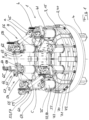
- die betreffende Radialpresse in perspektivischer Ansicht schräg von oben,
- Fig. 2
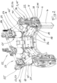
- aus einem ähnlichen Blickwinkel wie
Fig. 1 die in dieser gezeigte Radialpresse in geschnittener Darstellung, - Fig. 3
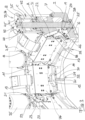
- einen Ausschnitt aus
Fig. 2 in vergrößertem Maßstab, - Fig. 4
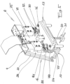
- in perspektivischer Ansicht schräg von oben eine der acht hydraulischen Zylinder-Kolben-Einheiten der in den
Figuren 1-3 gezeigten Radialpresse und - Fig. 5
- einen der acht Presskörper der Radialpresse nach den
Figuren 1-3 ohne die zugeordnete Verkleidung.
- Fig. 1
- the relevant radial press in a perspective view diagonally from above,
- Fig. 2
- from a similar perspective as
Fig. 1 the radial press shown in this in a sectional view, - Fig. 3
- a section
Fig. 2 on an enlarged scale, - Fig. 4
- in a perspective view diagonally from above one of the eight hydraulic cylinder-piston units in the
Figures 1-3 shown radial press and - Fig. 5
- one of the eight press bodies of the radial press according to the
Figures 1-3 without the associated fairing.
Die in der Zeichnung veranschaulichte, zum Betrieb mit vertikaler Pressachse X konzipierte Radialpresse 1 umfasst eine erste, untere Ringstruktur 2 und eine zweite, obere Ringstruktur 3. Beide Ringstrukturen 2, 3 erstrecken sich um die Pressachse X herum. Die untere Ringstruktur 2 ist dabei als stationäre Ringstruktur ausgeführt und stützt sich über Träger 4 auf demThe radial press 1 illustrated in the drawing and designed for operation with a vertical press axis X comprises a first,
Untergrund ab. Die zweite, obere Ringstruktur 3 ist mittels eines - acht um die Pressachse herum angeordnete und zu dieser parallel orientierte Aktuatoren C umfassenden - Antriebssystems anheb- und absenkbar, d. h. der Abstand der oberen Ringstruktur 3 zu der unteren Ringstruktur 2 lässt sich mittels des Antriebsystems verringern und vergrößern. Die untere Ringstruktur weist eine (im Zentrum durchbrochene!) topfartige Grundform auf, indem sie über einen Bodenring 6 und eine von diesem aufragende im Wesentlichen zylindrische Wandung 7 verfügt; sie ist so dimensioniert, dass die abgesenkte obere Ringstruktur 3 in dem Sinne in die untere Ringstruktur 2 eintritt, dass sie und die zylindrische Wandung 7 der unteren Ringstruktur 2 einander überlappen.underground. The second, upper ring structure 3 can be raised and lowered by means of a drive system - eight actuators C arranged around the press axis and comprising parallel oriented actuators C, ie the distance between the upper ring structure 3 and the
Weiterhin umfasst die Radialpresse acht gleichmäßig um die Pressachse X herum angeordnete Presskörper 8, welche sich jeweils - über zugeordnete obere Gegenflächen 9 und untere Gegenflächen 10 - gleitend verschiebbar an einer der oberen Ringstruktur 3 zugeordneten oberen ebenen Stützfläche 11 sowie einer der unteren Ringstruktur 2 zugeordneten unteren ebenen Stützfläche 12 abstützen. Die oberen Stützflächen 11 sind dabei jeweils auf der Oberfläche eines auswechselbaren oberen Gleitblechs 13 ausgeführt, und die unteren Stützflächen 12 jeweils auf der Oberfläche eines auswechselbaren unteren Gleitblechs 14. Während die unteren Stützflächen 12 (sowie die zugeordneten unteren Gegenflächen 10) auf der Pressachse X senkrecht stehen, sind die oberen Stützflächen 11 (sowie die zugeordneten oberen Gegenflächen 9) zu der Pressachse X geneigt orientiert. So stellen die oberen Stützflächen 11 "Steuerflächen" dar, über welche eine Axialbewegung der oberen Ringstruktur 3 in eine Radialbewegung der Presskörper 8 umgesetzt wird. Die obere Ringstruktur 3 bildet somit einen "Steuerring" 15.Furthermore, the radial press comprises eight pressed
Die Presskörper 8 umfassen Grundbacken 16, an welchen die oberen und unteren Gegenflächen 9 bzw. 10 ausgeführt sind, und auswechselbar an den Grundbacken 16 anbringbare Pressbacken 17. Jede der Grundbacken 16 - deren Erstreckung parallel zur Pressachse X ist etwa doppelt so groß wie quer zu dieser - ist an der oberen Ringstruktur 3 über eine obere Zwangsführung 18 und an der unteren Ringstruktur 2 über eine untere Zwangsführung 19 dergestalt geführt, dass sie (zumindest im Wesentlichen) spielfrei auf den beiden zugeordneten Stützflächen 11 bzw. 12 gehalten wird, d. h. nicht von diesen abgehoben werden kann. Die obere Zwangsführung 18 umfasst dabei zwei seitlich an der betreffenden Grundbacke 16 eingearbeitete, sich parallel zu der oberen Gegenfläche 9 erstreckende Führungsnuten 20 und in diese eingreifende, an der oberen Ringstruktur 3 angeordnete Führungskörper 21 in Form von an einem (oberen) Rollenträger 22 angebrachten Rollenanordnungen 23. Entsprechendes gilt für die untere Zwangsführung 19 mit ihren Führungsnuten 24 und an (unteren) Rollenträgern 25 angebrachten Rollenanordnungen 26. Die einzelnen Rollen sind dabei jeweils auf einem als Verstell-Exzenter ausgeführten Bolzen gelagert. Zur Führung der Grundbacken 16 in Umfangsrichtung sind an den oberen Rollenträgern 22 jeweils eine Stützfläche definierende Gleitbleche 27 angebracht, an denen sich die Grundbacken 16 über zugeordnete Gegenflächen 28 abstützen.The pressed
Mindestens einem Teil der Presskörper 8 ist jeweils eine Wegmesseinrichtung 29 (mit parallel zu den unteren Zwangsführungen 19, d. h. radial orientierter Messrichtung) zugeordnet, mittels derer sich jeweils die relative Lage der betreffenden Grundbacke 16 bezogen auf die untere Ringstruktur 2 erfassen lässt. Die betreffende Wegmesseinrichtung 29 umfasst einen mit der betreffenden Grundbacke 16 verbundenen, von dieser nach unten abstehenden Stift 30 mit einem endseitig daran angeordneten Aufnehmer 31, welcher mit einem zugeordneten, an der unteren Ringstruktur 2 fixierten, sich radial erstreckenden Messlineal 32 zusammenwirkt.At least one part of the pressed
Das für die Relativbewegung der beiden Ringstrukturen 2 und 3 bezüglich einander zum Einsatz kommende Antriebssystem ist hydraulisch ausgeführt; es umfasst - als Aktuatoren C - acht parallel zu der Pressachse X orientierte hydraulische Zylinder-Kolben-Einheiten 33 und eine (nicht dargestellte, üblich ausgeführte) Druckversorgungseinheit mit einem Tank, einer Motor-Pumpe-Einheit und einer Steuerung. Die - jeweils zu den Presskörpern 8 auf Lücke angeordneten - hydraulischen Zylinder-Kolben-Einheiten 33 sind als Gleichgangzylinder 34 ausgeführt. Der Zylinder 35 ist jeweils über einen zugeordneten, an dem Zylinderboden 36 ausgebildeten Flansch 37 mit der oberen Ringstruktur 3 (Steuerring 15) fest verbunden. Das untere Ende 38 der jeweiligen sich durch den Zylinder 35 hindurch erstreckenden Kolbenstange 39 ist demgegenüber mit der unteren Ringstruktur 2 ("Stützring" 40) fest verbunden.The drive system used for the relative movement of the two
Bei jeder hydraulischen Zylinder-Kolben-Einheit 33 sind innerhalb des jeweiligen, oben durch einen durchbohrtenDeckel 41 abgeschlossenen Zylinders 35 zwei durch den mit der Kolbenstange 39 fest verbundenen Kolben 42 voneinander abgegrenzte hydraulische Arbeitsräume A und B definiert. Diese werden durch die durchbohrte Kolbenstange 39 hindurch versorgt. Auf dem oberen Ende 43 der durch den Durchbruch 44 des Deckels 41 hindurch tretenden Kolbenstange 39 - bzw. gegebenenfalls auf einer mit diesem verbundenen Montageplatte (s. u.) - ist eine Ventileinheit 45 aufgebaut. Diese weist jeweils vier Anschlüsse a, b, c, d auf; über zwei von diesen (Anschlüsse a und b) kommuniziert sie mit der Druckversorgungseinheit, wohingegen die beiden anderen Anschlüsse c und d mit den die beiden Arbeitsräume A bzw. B versorgenden, sich innerhalb der Kolbenstange 39 erstreckenden Versorgungskanälen 46 bzw. 47 kommunizieren. Die beiden in die jeweilige Ventileinheit 45 integrierten, über einen elektrischen Aktuator 48 betätigbaren Schaltventile 49 erlauben ein Umschalten zwischen einerseits einer fluidischen Kommunikation der beiden Arbeitsräume A und B mit der Druckversorgungseinheit (über jeweils eine Durchlass-Verbindung des Anschlusses a mit dem Anschluss c und des Anschlusses b mit dem Anschluss d) und andererseits einen direkten hydraulischen Kurzschluss der beiden Arbeitsräume A und B über einen internen, die Anschlüsse c und d miteinander strömungstechnisch verbindenden Bypass 50. In der besagten zweiten Schaltstellung sind die beiden Arbeitsräume A und B mittels der Schaltventile 49 gegenüber der Druckversorgungseinheit abgesperrt.In each hydraulic cylinder-piston unit 33, within the
Die besagten Bypasse 50 werden geöffnet, wenn eine Eilverstellung der beiden Ringstrukturen 2 und 3 zueinander mittels eines Eil-Verstellantriebs 51 erfolgt. Dieser ist elektromechanisch ausgeführt und umfasst eine Antriebseinheit 52, vier Versteller 53 und einen die Antriebseinheit 52 mit den vier Verstellern 53 verbindenden, Wellen 54 und Umlenkgetriebe 55 aufweisenden Antriebsstrang 56. Jeder der vier (als Zahnstangentrieb 57 ausgeführten) Versteller 53 ist - zwischen dem Zylinder 35 und der Kolbenstange 39 wirkend - einer hydraulischen Zylinder-Kolben-Einheit 33 zugeordnet. Hierzu steht mit einer am Deckel 41 der jeweils zugeordneten hydraulischen Zylinder-Kolben-Einheit 33 fixierten Zahnstange 58 ein Zahnrad im Eingriff, welches in einem Zahntrieb-Gehäuse 59 drehbar gelagert ist. Das Zahntrieb-Gehäuse 59 ist dabei auf einer Montageplatte 60 aufgebaut, welche ihrerseits mit dem aus dem Deckel 41 hinausragenden Endabschnitt der Kolbenstange 39 der betreffenden hydraulischen Zylinder-Kolben-Einheit 33 fest verbundenen ist. Funktional parallel zu den vier Verstellern 53 sind vier Wegmesssysteme 61 vorgesehen mit jeweils einem an dem Deckel 41 der zugeordneten hydraulischen Zylinder-Kolben-Einheit 33 fixierten Messlineal 62 und einem an der betreffenden Montageplatte 60 fixierten Aufnehmer 63.Said bypasses 50 are opened when a rapid adjustment of the two
Die ebenfalls (zumindest indirekt) lagefest mit der Kolbenstange 39 der betreffenden hydraulischen Zylinder-Kolben-Einheit 33 verbundene, insbesondere auf der dieser zugeordneten Ventileinheit 45 aufgebaute Antriebseinheit 52 umfasst einen Servomotor 64 mit einem angeflanschten selbsthemmenden Planetengetriebe 65, eine elektromechanische Trennkupplung 66, einen der Handbetätigung dienenden Eingang 67 und ein Verteilergetriebe 68 mit zwei Ausgängen 69, an welchen zugeordnete Wellen 54 des Antriebsstrangs 56 angeschlossen sind.The
Die aus der oberen Ringstruktur 3 und den acht mit ihr verbundenen Zylindern 35 der hydraulischen Zylinder-Kolben-Einheiten 33 bestehende Einheit stützt sich zumindest im Umfang eines wesentlichen Teils ihrer Masse über Federelemente 70 auf der unteren Ringstruktur 2 ab. Hierzu erstrecken sich Gasfedern 71 zwischen jeweils einem der unteren Ringstruktur 2 zugeordneten unteren Anlenkpunkt 72 und einem dem Deckel 41 einer hydraulischen Zylinder-Kolben-Einheit 33 zugeordneten oberen Anlenkpunkt 73.The unit consisting of the upper ring structure 3 and the eight
Was die Fixierung der auswechselbar an den Grundbacken 16 anbringbaren Pressbacken 17 an den Grundbacken 16 betrifft, so sind hierfür - im betriebsfertigen Zustand der Radialpresse 1 durch jeweils eine Verkleidung 74 geschützt - hydraulisch betätigbare Verriegelungen vorgesehen, welche eine automatisierte Bestückung der acht Grundbacken 16 mit einem Pressbackensatz ermöglichen. Die Verriegelungen umfassen jeweils eine - an dem Grundbacken-Grundkörper 75 angebrachte Klemmeinheit 76 mit einer schwenkbar angetriebene Klaue, welche die jeweilige - auf der Armierungsschiene 77 des Grundbacken-Grundkörper 75 aufliegende - Pressbacke 17 radial nach außen in ihre durch die Anschläge 78 definierte Verriegelungsposition zieht. Weiterhin umfasst die Verriegelung jeweils zwei paarweise an dem Grundbacken-Grundkörper 75 angeordnete Hydraulikzylinder 79 mit an der jeweiligen Kolbenstange angebrachten Verriegelungsköpfen 80, welche die betreffende Pressbacke 17 in die zugeordnete Aufnahme des Grundbacken-Grundkörpers 75 drücken. Eine mechanische Feder 81 unterstützt dabei jeweils den betreffenden Hydraulikzylinder 79 und stellt sicher, dass die betreffende Pressbacke 17 auch ohne Fremdenergie an der jeweiligen Grundbacke 16 gehalten wird, d. h. nicht durch ihr Eigengewicht kippt. Die Stellung der Verriegelungsköpfe 80 wird mittels Sensoren 82 erfasst, welche über Winkel 83 an dem Grundbacken-Grundkörper 75 angebracht sind.As far as fixing the
Claims (15)
- A radial press (1) with a first and a second ring structure (2; 3) extending around a press axis (X) and, disposed between them around the press axis (X), several pressing elements (8) displaceably braced at bracing faces (11; 12) associated with the ring structures (2; 3), wherein the axial distance of the two ring structures (2, 3) from one another can be varied by means of a drive system, which comprises a multiplicity of actuators (C) oriented parallel to the press axis (X) and disposed in distributed manner around it, of which respectively a first component is coupled with a first of the two ring structures and a second component, actively movable relative to the first component, is coupled with the second ring structure, and wherein furthermore at least the bracing faces (11) associated with one of the two ring structures (3) are oriented at an inclination to the press axis (X) and the pressing elements (8) are guided compulsorily relative to the two ring structures (2, 3),
characterized in that the compulsory guidance (18, 19) takes place respectively via, associated with the pressing elements (8) and the ring structure (2, 3) in question, pairs of guide slots (20, 24) made in the pressing elements (8) and guide elements (21), comprising guide rollers (23, 26), engaging in these guide slots. - The radial press of claim 1, characterized in that the guide rollers (23, 26) are respectively mounted on a bolt constructed as a positioning cam.
- The radial press of claim 1 or claim 2, characterized in that the pressing elements (8) comprise base jaws (16) and pressing jaws (17) that can be fastened exchangeably to these.
- The radial press of claim 3, characterized in that the extent of the base jaws (16) parallel to the press axis (X) is at least twice as large as transversely relative thereto and/or that a hydraulically actuatable interlock system acts between the base jaws (16) and the pressing jaws (17).
- The radial press of one of claims 1 to 4, characterized in that only the bracing faces (11) associated with one of the two ring structures (2, 3) are inclined relative to the press axis (X), whereas the bracing faces (12) associated with the other ring structure (2) are oriented perpendicular to the press axis (X).
- The radial press of claim 5, characterized in that the ring structure (2) having bracing faces (12) oriented perpendicular to the press axis (X) is constructed as a stationary ring structure (40).
- The radial press of claim 6, characterized in that a displacement-measuring device (29) with radially oriented measuring direction acts between the stationary ring structure (40) and at least one of the pressing elements (8).
- The radial press of one of claims 1 to 7, characterized in that the press axis (X) is vertically oriented, wherein one of the ring structures forms a lower ring structure (2) and the other ring structure forms an upper ring structure (3), wherein preferably the lower ring structure (2) is braced via a load-bearing structure (4) on the foundation but is spaced apart from it.
- The radial press of claim 8, characterized in that the upper ring structure (3) is braced on the lower ring structure (2) at least in the scope of a substantial part of its own mass as well as of that of the components, associated with it, of the actuators via spring elements (70), wherein preferably spring elements (70) constructed as gas springs (71) act between the lower ring structure (2) and the components, associated with the upper ring structure (3), of the actuators.
- The radial press of one of claims 1 to 9, characterized in that a hydraulic drive system is provided wherein the actuators (C) are constructed as hydraulic cylinder-piston units (33), of which respectively the cylinder (35) forms the first component and the piston rod (39) forms the second component of the actuator (C) in question.
- The radial press of claim 10, characterized in that the cylinder-piston units (33) are constructed as synchronizing cylinders (34), wherein preferably a valve unit (45) permitting a direct hydraulic short circuit of the two working chambers (A, B) of the synchronizing cylinder (34) in question is associated with each synchronizing cylinder (34).
- The radial press of claim 11, characterized in that the valve units (45) are disposed respectively at the end of the associated piston rod (39), provided with supply ducts (46, 47).
- The radial press of one of claims 1 to 12, characterized in that an electromechanical rapid positioning drive (51) comprising several positioners (53) is provided.
- The radial press of claim 13, characterized in that the rapid positioning drive (51) comprises a common servo motor (64) acting on all positioners (53).
- The radial press of claim 13 or claim 14, characterized in that the positioners (53) act respectively between the components, actively positionable relative to one another, of an actuator, especially between the cylinder (35) and the piston rod (39) of a hydraulic cylinder-piston unit (33).
Applications Claiming Priority (2)
| Application Number | Priority Date | Filing Date | Title |
|---|---|---|---|
| DE102020121142.2A DE102020121142B4 (en) | 2020-08-11 | 2020-08-11 | radial press |
| PCT/EP2021/070350 WO2022033819A1 (en) | 2020-08-11 | 2021-07-21 | Radial press |
Publications (2)
| Publication Number | Publication Date |
|---|---|
| EP4132777A1 EP4132777A1 (en) | 2023-02-15 |
| EP4132777B1 true EP4132777B1 (en) | 2023-10-18 |
Family
ID=77104083
Family Applications (1)
| Application Number | Title | Priority Date | Filing Date |
|---|---|---|---|
| EP21746743.0A Active EP4132777B1 (en) | 2020-08-11 | 2021-07-21 | Radial press |
Country Status (6)
| Country | Link |
|---|---|
| US (1) | US20230114893A1 (en) |
| EP (1) | EP4132777B1 (en) |
| CN (1) | CN115916517A (en) |
| DE (1) | DE102020121142B4 (en) |
| FI (1) | FI4132777T3 (en) |
| WO (1) | WO2022033819A1 (en) |
Family Cites Families (14)
| Publication number | Priority date | Publication date | Assignee | Title |
|---|---|---|---|---|
| FR2341093A1 (en) | 1976-02-13 | 1977-09-09 | Anoflex Flexibles | Machine attaching end fittings to flexible hydraulic pipes - is actuated by three small hydraulic jacks and has fingers pushed against tapered core of ring |
| US4550587A (en) | 1983-12-15 | 1985-11-05 | The Goodyear Tire & Rubber Company | Heavy duty hose crimper |
| DE3512241A1 (en) | 1985-04-03 | 1986-10-16 | Peter Dipl Ing Schroeck | RADIAL PRESS |
| DE3611253A1 (en) | 1986-04-04 | 1987-10-08 | Peter Dipl Ing Schroeck | RADIAL PRESS |
| JP3281175B2 (en) | 1994-04-18 | 2002-05-13 | 株式会社東芝 | Press forming equipment |
| DE19861171B4 (en) * | 1998-04-22 | 2005-09-22 | Uniflex-Hydraulik Gmbh | radial press |
| DE20017791U1 (en) | 2000-10-17 | 2000-12-28 | Uniflex Hydraulik Gmbh | Press jaw set for a radial press |
| DE10149924A1 (en) | 2001-10-10 | 2003-04-30 | Uniflex Hydraulik Gmbh | radial press |
| DE102005041487A1 (en) | 2005-08-30 | 2007-04-05 | Ekf Werkzeug Und Maschinenbau Gmbh | Radial press has four diametrically opposed press jaws, equally distributed between two press frames linked to a central drive unit |
| DE102006036654B4 (en) | 2006-08-03 | 2008-12-04 | Harald Weigelt | Wedge drive with forced return device |
| DE102009057726A1 (en) * | 2009-12-10 | 2011-06-16 | Uniflex-Hydraulik Gmbh | radial press |
| ES2401712T3 (en) * | 2010-08-20 | 2013-04-23 | Op S.R.L. | Gripper to hold the tools of a radial press |
| DE102016106650B4 (en) * | 2016-04-12 | 2021-09-16 | Uniflex-Hydraulik Gmbh | Radial press |
| DE102017119403A1 (en) | 2017-08-24 | 2019-02-28 | Uniflex-Hydraulik Gmbh | Radial press system |
-
2020
- 2020-08-11 DE DE102020121142.2A patent/DE102020121142B4/en active Active
-
2021
- 2021-07-21 WO PCT/EP2021/070350 patent/WO2022033819A1/en unknown
- 2021-07-21 CN CN202180043048.9A patent/CN115916517A/en active Pending
- 2021-07-21 EP EP21746743.0A patent/EP4132777B1/en active Active
- 2021-07-21 FI FIEP21746743.0T patent/FI4132777T3/en active
-
2022
- 2022-12-08 US US18/077,885 patent/US20230114893A1/en active Pending
Also Published As
| Publication number | Publication date |
|---|---|
| FI4132777T3 (en) | 2024-01-09 |
| US20230114893A1 (en) | 2023-04-13 |
| DE102020121142A1 (en) | 2022-02-17 |
| EP4132777A1 (en) | 2023-02-15 |
| CN115916517A (en) | 2023-04-04 |
| DE102020121142B4 (en) | 2022-03-10 |
| WO2022033819A1 (en) | 2022-02-17 |
Similar Documents
| Publication | Publication Date | Title |
|---|---|---|
| EP2509725B1 (en) | Radial press | |
| AT509239B1 (en) | DRIVE DEVICE FOR A BEND PRESS | |
| EP3442784B1 (en) | Radial press | |
| DE102012209077B4 (en) | Clamping device for clamping a rod-like workpiece and machine tool so | |
| DE102007051894A1 (en) | Release mechanism and provided with this straightening device | |
| DE102006019207B4 (en) | Drive system of a multi-tappet forming press | |
| EP4132777B1 (en) | Radial press | |
| EP4135973B1 (en) | Radial press | |
| AT507110A1 (en) | Press for material shaping, has head piece with plunger moved up and down with respect to table, where head piece is moveable platform of parallel kinematic device, whose stationary platform is fixed in position with respect to table | |
| WO2001056776A1 (en) | Press | |
| AT509907B1 (en) | Locking unit for an injection molding machine | |
| EP0051121B1 (en) | Spinning machine | |
| EP0002032B1 (en) | Method and apparatus for making multiple-groove pulleys | |
| WO2005021253A2 (en) | Hydraulic press and deep-drawing press | |
| EP3024646B1 (en) | Force module and modular press system | |
| EP0125540B1 (en) | Apparatus for making tubes with holes in the walls | |
| DE102004006126A1 (en) | Hydraulic press has press ram locked to lower belt after advancing stroke by piston rods of hydraulic piston-cylinder units | |
| WO2010094383A2 (en) | Device for the production of molded articles | |
| EP0268681A1 (en) | Double action screw-press | |
| EP0659501B1 (en) | Forging machine | |
| EP1344585B1 (en) | Hydroelastic deep drawing device | |
| DE19809371A1 (en) | Coupling for connecting workpiece grippers to a handling device | |
| DE19607257A1 (en) | Hydraulic pressing machine for shaping sheet metal parts | |
| DE4444497A1 (en) | Forging machine | |
| DE102023123181A1 (en) | Device for producing moldings, in particular stone moldings for masonry stones, and method for changing a format of moldings to be produced |
Legal Events
| Date | Code | Title | Description |
|---|---|---|---|
| STAA | Information on the status of an ep patent application or granted ep patent |
Free format text: STATUS: UNKNOWN |
|
| STAA | Information on the status of an ep patent application or granted ep patent |
Free format text: STATUS: THE INTERNATIONAL PUBLICATION HAS BEEN MADE |
|
| PUAI | Public reference made under article 153(3) epc to a published international application that has entered the european phase |
Free format text: ORIGINAL CODE: 0009012 |
|
| STAA | Information on the status of an ep patent application or granted ep patent |
Free format text: STATUS: REQUEST FOR EXAMINATION WAS MADE |
|
| 17P | Request for examination filed |
Effective date: 20221110 |
|
| AK | Designated contracting states |
Kind code of ref document: A1 Designated state(s): AL AT BE BG CH CY CZ DE DK EE ES FI FR GB GR HR HU IE IS IT LI LT LU LV MC MK MT NL NO PL PT RO RS SE SI SK SM TR |
|
| GRAP | Despatch of communication of intention to grant a patent |
Free format text: ORIGINAL CODE: EPIDOSNIGR1 |
|
| STAA | Information on the status of an ep patent application or granted ep patent |
Free format text: STATUS: GRANT OF PATENT IS INTENDED |
|
| INTG | Intention to grant announced |
Effective date: 20230512 |
|
| P01 | Opt-out of the competence of the unified patent court (upc) registered |
Effective date: 20230529 |
|
| GRAS | Grant fee paid |
Free format text: ORIGINAL CODE: EPIDOSNIGR3 |
|
| GRAA | (expected) grant |
Free format text: ORIGINAL CODE: 0009210 |
|
| STAA | Information on the status of an ep patent application or granted ep patent |
Free format text: STATUS: THE PATENT HAS BEEN GRANTED |
|
| AK | Designated contracting states |
Kind code of ref document: B1 Designated state(s): AL AT BE BG CH CY CZ DE DK EE ES FI FR GB GR HR HU IE IS IT LI LT LU LV MC MK MT NL NO PL PT RO RS SE SI SK SM TR |
|
| DAV | Request for validation of the european patent (deleted) | ||
| DAX | Request for extension of the european patent (deleted) | ||
| REG | Reference to a national code |
Ref country code: GB Ref legal event code: FG4D Free format text: NOT ENGLISH |
|
| REG | Reference to a national code |
Ref country code: CH Ref legal event code: EP |
|
| REG | Reference to a national code |
Ref country code: DE Ref legal event code: R096 Ref document number: 502021001751 Country of ref document: DE |
|
| REG | Reference to a national code |
Ref country code: IE Ref legal event code: FG4D Free format text: LANGUAGE OF EP DOCUMENT: GERMAN |
|
| REG | Reference to a national code |
Ref country code: LT Ref legal event code: MG9D |
|
| REG | Reference to a national code |
Ref country code: NL Ref legal event code: MP Effective date: 20231018 |
|
| PG25 | Lapsed in a contracting state [announced via postgrant information from national office to epo] |
Ref country code: NL Free format text: LAPSE BECAUSE OF FAILURE TO SUBMIT A TRANSLATION OF THE DESCRIPTION OR TO PAY THE FEE WITHIN THE PRESCRIBED TIME-LIMIT Effective date: 20231018 |
|
| PG25 | Lapsed in a contracting state [announced via postgrant information from national office to epo] |
Ref country code: GR Free format text: LAPSE BECAUSE OF FAILURE TO SUBMIT A TRANSLATION OF THE DESCRIPTION OR TO PAY THE FEE WITHIN THE PRESCRIBED TIME-LIMIT Effective date: 20240119 |
|
| PG25 | Lapsed in a contracting state [announced via postgrant information from national office to epo] |
Ref country code: IS Free format text: LAPSE BECAUSE OF FAILURE TO SUBMIT A TRANSLATION OF THE DESCRIPTION OR TO PAY THE FEE WITHIN THE PRESCRIBED TIME-LIMIT Effective date: 20240218 |
|
| PG25 | Lapsed in a contracting state [announced via postgrant information from national office to epo] |
Ref country code: LT Free format text: LAPSE BECAUSE OF FAILURE TO SUBMIT A TRANSLATION OF THE DESCRIPTION OR TO PAY THE FEE WITHIN THE PRESCRIBED TIME-LIMIT Effective date: 20231018 |