EP4132440B1 - Gewebeschnittstelle für unterdruck- und instillationstherapie - Google Patents
Gewebeschnittstelle für unterdruck- und instillationstherapie Download PDFInfo
- Publication number
- EP4132440B1 EP4132440B1 EP21720845.3A EP21720845A EP4132440B1 EP 4132440 B1 EP4132440 B1 EP 4132440B1 EP 21720845 A EP21720845 A EP 21720845A EP 4132440 B1 EP4132440 B1 EP 4132440B1
- Authority
- EP
- European Patent Office
- Prior art keywords
- contact layer
- pressure
- tissue
- holes
- negative
- Prior art date
- Legal status (The legal status is an assumption and is not a legal conclusion. Google has not performed a legal analysis and makes no representation as to the accuracy of the status listed.)
- Active
Links
Images


Classifications
-
- A—HUMAN NECESSITIES
- A61—MEDICAL OR VETERINARY SCIENCE; HYGIENE
- A61F—FILTERS IMPLANTABLE INTO BLOOD VESSELS; PROSTHESES; DEVICES PROVIDING PATENCY TO, OR PREVENTING COLLAPSING OF, TUBULAR STRUCTURES OF THE BODY, e.g. STENTS; ORTHOPAEDIC, NURSING OR CONTRACEPTIVE DEVICES; FOMENTATION; TREATMENT OR PROTECTION OF EYES OR EARS; BANDAGES, DRESSINGS OR ABSORBENT PADS; FIRST-AID KITS
- A61F13/00—Bandages or dressings; Absorbent pads
- A61F13/02—Adhesive bandages or dressings
- A61F13/023—Adhesive bandages or dressings wound covering film layers without a fluid retention layer
- A61F13/0233—Adhesive bandages or dressings wound covering film layers without a fluid retention layer characterised by the oclusive layer skin contacting layer
-
- A—HUMAN NECESSITIES
- A61—MEDICAL OR VETERINARY SCIENCE; HYGIENE
- A61F—FILTERS IMPLANTABLE INTO BLOOD VESSELS; PROSTHESES; DEVICES PROVIDING PATENCY TO, OR PREVENTING COLLAPSING OF, TUBULAR STRUCTURES OF THE BODY, e.g. STENTS; ORTHOPAEDIC, NURSING OR CONTRACEPTIVE DEVICES; FOMENTATION; TREATMENT OR PROTECTION OF EYES OR EARS; BANDAGES, DRESSINGS OR ABSORBENT PADS; FIRST-AID KITS
- A61F13/00—Bandages or dressings; Absorbent pads
- A61F13/05—Bandages or dressings; Absorbent pads specially adapted for use with sub-pressure or over-pressure therapy, wound drainage or wound irrigation, e.g. for use with negative-pressure wound therapy [NPWT]
Definitions
- Negative-pressure therapy may provide a number of benefits, including migration of epithelial and subcutaneous tissues, improved blood flow, and micro-deformation of tissue at a wound site. Together, these benefits can increase development of granulation tissue and reduce healing times.
- WO2020/036785 discloses a negative pressure wound therapy device with a modulating layer formed from an open-cell foam and a macro-column layer formed from a felted foam.
- US2015/0320434 discloses a negative pressure wound therapy system with a contact layer having a walls defining a plurality of through holes.
- tissue site in this context broadly refers to a wound, defect, or other treatment target located on or within tissue, including but not limited to, a surface wound, bone tissue, adipose tissue, muscle tissue, neural tissue, dermal tissue, vascular tissue, connective tissue, cartilage, tendons, or ligaments.
- tissue site may also refer to areas of any tissue that are not necessarily wounded or defective, but are instead areas in which it may be desirable to add or promote the growth of additional tissue. For example, negative pressure may be applied to a tissue site to grow additional tissue that may be harvested and transplanted.
- FIG. 1 is a simplified functional block diagram of an example embodiment of a therapy system 100 that can provide negative-pressure therapy with instillation of topical treatment solutions to a tissue site in accordance with this specification.
- the therapy system 100 may include a source or supply of negative pressure, such as a negative-pressure source 102, a dressing 104, a fluid container, such as a container 106, and a regulator or controller, such as a controller 108, for example.
- the therapy system 100 may include sensors to measure operating parameters and provide feedback signals to the controller 108 indicative of the operating parameters.
- the therapy system 100 may include a pressure sensor 110, an electric sensor 112, or both, coupled to the controller 108.
- the dressing 104 may comprise or consist essentially of a contact layer 202, a cover 116, or both in some embodiments.
- the instillation regulator 122 may comprise a piston that can be pneumatically actuated by the negative-pressure source 102 to draw instillation solution from the solution source during a negative-pressure interval and to instill the solution to a dressing during a venting interval.
- the controller 108 may be coupled to the negative-pressure source 102, the positive-pressure source 120, or both, to control dosage of instillation solution to a tissue site.
- the instillation regulator 122 may also be fluidly coupled to the negative-pressure source 102 through the dressing 104, as illustrated in the example of Figure 1 .
- Some components of the therapy system 100 may be housed within or used in conjunction with other components, such as sensors, processing units, alarm indicators, memory, databases, software, display devices, or user interfaces that further facilitate therapy.
- the negative-pressure source 102 may be combined with the solution source 118, the controller 108, and other components into a therapy unit.
- components of the therapy system 100 may be coupled directly or indirectly.
- the negative-pressure source 102 may be directly coupled to the container 106, and may be indirectly coupled to the dressing 104 through the container 106. Coupling may include fluid, mechanical, thermal, electrical, or chemical coupling (such as a chemical bond), or some combination of coupling in some contexts.
- the negative-pressure source 102 may be electrically coupled to the controller 108, and may be fluidly coupled to one or more distribution components to provide a fluid path to a tissue site.
- components may also be coupled by virtue of physical proximity, being integral to a single structure, or being formed from the same piece of material.
- the contact layer 202 and the cover 116 may be discrete layers disposed adjacent to each other, and may be joined together in some embodiments.
- a distribution component is preferably detachable, and may be disposable, reusable, or recyclable.
- the dressing 104 and the container 106 are illustrative of distribution components.
- a fluid conductor is another illustrative example of a distribution component.
- a tube is an elongated, cylindrical structure with some flexibility, but the geometry and rigidity may vary.
- some fluid conductors may be molded into or otherwise integrally combined with other components.
- Distribution components may also include or comprise interfaces or fluid ports to facilitate coupling and de-coupling other components. In some embodiments, for example, a dressing interface may facilitate coupling a fluid conductor to the dressing 104.
- a negative-pressure supply such as the negative-pressure source 102, may be a reservoir of air at a negative pressure, or may be a manual or electrically-powered device, such as a vacuum pump, a suction pump, a wall suction port available at many healthcare facilities, or a micro-pump, for example.
- Negative pressure generally refers to a pressure less than a local ambient pressure, such as the ambient pressure in a local environment external to a sealed therapeutic environment. In many cases, the local ambient pressure may also be the atmospheric pressure at which a tissue site is located. Alternatively, the pressure may be less than a hydrostatic pressure associated with tissue at the tissue site. Unless otherwise indicated, values of pressure stated herein are gauge pressures.
- the container 106 is representative of a container, canister, pouch, or other storage component, which can be used to manage exudates and other fluids withdrawn from a tissue site.
- a rigid container may be preferred or required for collecting, storing, and disposing of fluids.
- fluids may be properly disposed of without rigid container storage, and a re-usable container could reduce waste and costs associated with negative-pressure therapy.
- a controller such as the controller 108, may be a microprocessor or computer programmed to operate one or more components of the therapy system 100, such as the negative-pressure source 102.
- the controller 108 may be a microcontroller, which generally comprises an integrated circuit containing a processor core and a memory programmed to directly or indirectly control one or more operating parameters of the therapy system 100. Operating parameters may include the power applied to the negative-pressure source 102, the pressure generated by the negative-pressure source 102, or the pressure distributed to the contact layer 202, for example.
- the controller 108 is also preferably configured to receive one or more input signals, such as a feedback signal, and programmed to modify one or more operating parameters based on the input signals.
- Sensors such as the pressure sensor 110 or the electric sensor 112 are generally known in the art as any apparatus operable to detect or measure a physical phenomenon or property, and generally provide a signal indicative of the phenomenon or property that is detected or measured.
- the pressure sensor 110 and the electric sensor 112 may be configured to measure one or more operating parameters of the therapy system 100.
- the pressure sensor 110 may be a transducer configured to measure pressure in a pneumatic pathway and convert the measurement to a signal indicative of the pressure measured.
- the pressure sensor 110 may be a piezoresistive strain gauge.
- the electric sensor 112 may optionally measure operating parameters of the negative-pressure source 102, such as the voltage or current, in some embodiments.
- the signals from the pressure sensor 110 and the electric sensor 112 are suitable as an input signal to the controller 108, but some signal conditioning may be appropriate.
- the signal may need to be filtered or amplified before it can be processed by the controller 108.
- the signal is an electrical signal, but may be represented in other forms, such as an optical signal.
- the contact layer 202 can be generally adapted to partially or fully contact a tissue site.
- the contact layer 202 may take many forms, and may have many sizes, shapes, or thicknesses depending on a variety of factors, such as the type of treatment being implemented or the nature and size of a tissue site.
- the size and shape of the contact layer 202 may be adapted to the contours of deep and irregular shaped tissue sites.
- the cover 116 may provide a bacterial barrier and protection from physical trauma.
- the cover 116 may also be constructed from a material that can reduce evaporative losses and provide a fluid seal between two components or two environments, such as between a therapeutic environment and a local external environment.
- the cover 116 may be, for example, an elastomeric film or membrane that can provide a seal adequate to maintain a negative pressure at a tissue site for a given negative-pressure source.
- the cover 116 may have a high moisture-vapor transmission rate (MVTR) in some applications.
- the MVTR may be at least about 300 g/m 2 per twenty-four hours in some embodiments.
- the cover 116 may be a polymer drape, such as a polyurethane film, that is permeable to water vapor but impermeable to liquid.
- a polymer drape such as a polyurethane film
- Such drapes typically have a thickness in the range of about 25 microns to about 50 microns.
- the permeability generally should be low enough that a desired negative pressure may be maintained.
- the cover 116 may comprise, for example, one or more of the following materials: hydrophilic polyurethane; cellulosics; hydrophilic polyamides; polyvinyl alcohol; polyvinyl pyrrolidone; hydrophilic acrylics; hydrophilic silicone elastomers; an INSPIRE 2301 material from Coveris Advanced Coatings of Wrexham, United Kingdom having, for example, an MVTR (inverted cup technique) of about 14400 g/m 2 /24 hours and a thickness of about 30 microns; a thin, uncoated polymer drape; natural rubbers; polyisoprene; styrene butadiene rubber; chloroprene rubber; polybutadiene; nitrile rubber; butyl rubber; ethylene propylene rubber; ethylene propylene diene monomer; chlorosulfonated polyethylene; polysulfide rubber; polyurethane (PU); EVA film; copolyester; silicones; a silicone drape; a
- An attachment device may be used to attach the cover 116 to an attachment surface, such as undamaged epidermis, a gasket, or another cover.
- the attachment device may take many forms.
- an attachment device may be a medically-acceptable, pressure-sensitive adhesive configured to bond the cover 116 to epidermis around a tissue site.
- some or all of the cover 116 may be coated with an adhesive, such as an acrylic adhesive, which may have a coating weight between about 25 grams per square meter (g.s.m.) and about 65 g.s.m. Thicker adhesives, or combinations of adhesives, may be applied in some embodiments to improve the seal and reduce leaks.
- Other example embodiments of an attachment device may include a double-sided tape, paste, hydrocolloid, hydrogel, silicone gel, or organogel.
- the solution source 118 may also be representative of a container, canister, pouch, bag, or other storage component, which can provide a solution for instillation therapy.
- Compositions of solutions may vary according to a prescribed therapy, but examples of solutions that may be suitable for some prescriptions include hypochlorite-based solutions, silver nitrate (0.5%), sulfur-based solutions, biguanides, cationic solutions, and isotonic solutions.
- the fluid mechanics of using a negative-pressure source to reduce pressure in another component or location, such as within a sealed therapeutic environment, can be mathematically complex.
- the basic principles of fluid mechanics applicable to negative-pressure therapy and instillation are generally well-known to those skilled in the art, and the process of reducing pressure may be described illustratively herein as "delivering,” “distributing,” or “generating” negative pressure, for example.
- downstream typically implies a position in a fluid path relatively closer to a source of negative pressure or further away from a source of positive pressure.
- upstream implies a position relatively further away from a source of negative pressure or closer to a source of positive pressure.
- necrotic tissue may be dead tissue resulting from infection, toxins, or trauma that caused the tissue to die faster than the tissue can be removed by the normal body processes that regulate the removal of dead tissue.
- necrotic tissue may be in the form of slough, which may include a viscous liquid mass of tissue.
- slough is produced by bacterial and fungal infections that stimulate an inflammatory response in the tissue. Slough may be a creamy yellow color and may also be referred to as pus.
- Necrotic tissue may also include eschar. Eschar may be a portion of necrotic tissue that has become dehydrated and hardened. Eschar may be the result of a burn injury, gangrene, ulcers, fungal infections, spider bites, or anthrax. Eschar may be difficult to remove without the use of surgical cutting instruments.
- the tissue site may include biofilms, lacerated tissue, devitalized tissue, contaminated tissue, damaged tissue, infected tissue, exudate, highly viscous exudate, fibrinous slough and/or other material that can generally be referred to as debris.
- the debris may inhibit the efficacy of tissue treatment and slow the healing of the tissue site. If the debris is in the tissue site, the tissue site may be treated with different processes to disrupt the debris. Examples of disruption can include softening of the debris, separation of the debris from desired tissue, such as the subcutaneous tissue, preparation of the debris for removal from the tissue site, and removal of the debris from the tissue site.
- a manifold positioned at a tissue site to distribute negative-pressure across the tissue site may become blocked or clogged with debris broken down by an autolytic process. If a manifold becomes clogged, negative-pressure may not be able to remove debris, which can slow or stop the autolytic process.
- tissue in-growth may make it more likely that portions of the dressing remain in place following treatment, or may make it more likely that subsequent surgical procedures may be necessary to separate the tissue from the dressing.
- the therapy system 100 may be used in conjunction with other tissue removal and debridement techniques.
- the therapy system 100 may be used prior to enzymatic debridement to soften the debris.
- mechanical debridement may be used to remove a portion of the debris at the tissue site, and the therapy system 100 may then be used to remove the remaining debris while reducing the risk of trauma to the tissue site.
- the therapy system 100 may also provide a process of manufacturing the dressing without cutting or tearing the dressing, minimizing the risk of shedding particulates or and the risk of tissue ingrowth.
- Figure 2 is an assembly view of an example of the dressing 104 of Figure 1 , illustrating additional details that may be associated with some embodiments in which the contact layer 202 comprises multiple layers.
- the contact layer 202 can include a debridement tool, such as, a contact layer 202.
- the contact layer 202 may have a first surface 206, a contact surface, such as a second surface 208, and a plurality of debridement cavities or blind apertures, such as a plurality of holes 210 extending into the contact layer 202 from the second surface 208 toward the first surface 206.
- the contact layer 202 may also include a retainer layer.
- the retainer layer can be disposed over the contact layer 202.
- the retainer layer may be positioned adjacent to the first surface 206 of the contact layer 202.
- the contact layer 202 may have a substantially uniform thickness 212.
- the thickness 212 may be between about 7 mm and about 32 mm. In other embodiments, the thickness 212 may be thinner or thicker than the stated range as needed for the particular application of the dressing 104. In a preferred embodiment, the thickness 212 may be about 10 mm. In some embodiments, individual portions of the contact layer 202 may have a minimal tolerance from the thickness 212. In some embodiments, the thickness 212 may have a tolerance of about 2 mm.
- the contact layer 202 may be flexible so that the contact layer 202 can be contoured to a surface of the tissue site.
- the contact layer 202 may be formed from a foam.
- cellular foam, open-cell foam, reticulated foam, or porous tissue collections may be used to form the contact layer 202.
- the contact layer 202 may be a foam having pore sizes in a range of about 60 microns to about 2000 microns.
- the contact layer 202 may be a foam having pore sizes in a range of about 400 microns to about 600 microns.
- the tensile strength of the contact layer 202 may vary according to needs of a prescribed therapy. For example, the tensile strength of a foam may be increased for instillation of topical treatment solutions.
- the contact layer 202 may be an open-cell, reticulated polyurethane foam such as a V.A.C. VERAFLO TM dressing, also available from Kinetic Concepts, Inc., of San Antonio, Texas.
- the contact layer 202 may be formed of an un-reticulated open-cell foam.
- the contact layer 202 may be formed from a foam that is mechanically or chemically compressed, often as part of a thermoforming process, to increase the density of the foam at ambient pressure.
- a foam that is mechanically or chemically compressed may be referred to as a compressed foam or a felted foam.
- a compressed foam may be characterized by a firmness factor (FF) that is defined as a ratio of the density of a foam in a compressed state to the density of the same foam in an uncompressed state.
- FF firmness factor
- 5 may refer to a compressed foam having a density at ambient pressure that is five times greater than a density of the same foam in an uncompressed state at ambient pressure.
- a compressed or felted foam may have a firmness factor greater than 1.
- Mechanically or chemically compressing a foam may reduce a thickness of the foam at ambient pressure when compared to the same foam that has not been compressed. Reducing a thickness of a foam by mechanical or chemical compression may increase a density of the foam, which may increase the firmness factor (FF) of the foam. Increasing the firmness factor (FF) of a foam may increase a stiffness of the foam in a direction that is parallel to a thickness of the foam. For example, increasing a firmness factor (FF) of the contact layer 202 may increase a stiffness of the contact layer 202 in a direction that is parallel to the thickness 212 of the contact layer 202.
- a compressed foam may be a compressed V.A.C. ® GRANUFOAM TM Dressing.
- V.A.C. ® GRANUFOAM TM Dressing may have a density of about 0.03 grams per centimeter 3 (g/cm 3 ) in its uncompressed state. If the V.A.C. ® GRANUFOAM TM Dressing is compressed to have a firmness factor (FF) of 5, the V.A.C. ® GRANUFOAM TM Dressing may be compressed until the density of the V.A.C. ® GRANUFOAM TM Dressing is about 0.15g/cm 3 . V.A.C. VERAFLO TM dressing may also be compressed to form a compressed foam having a firmness factor (FF) up to 5. For example, V.A.C.
- VERAFLO TM Dressing may have a density between about 1.7 pounds per foot 3 (lb/ft 3 ) or 0.027 grams per centimeter 3 (g/cm 3 ) and about 2.1 lb/ft 3 or 0.034 g/cm 3 . If the V.A.C. VERAFLO TM Dressing is compressed to have a firmness factor (FF) of 5, the V.A.C. VERAFLO TM Dressing may be compressed until the density of the V.A.C. VERAFLO TM Dressing is between about 0.135 g/cm 3 and about 0.17 g/cm 3 .
- FF firmness factor
- the compressed foam exhibits less deformation than a similar uncompressed foam.
- the contact layer 202 is formed of a compressed foam
- the thickness 212 of the contact layer 202 may deform less than if the contact layer 202 is formed of a comparable uncompressed foam.
- the decrease in deformation may be caused by the increased stiffness as reflected by the firmness factor (FF).
- FF firmness factor
- the contact layer 202 that is formed of compressed foam may flatten less than the contact layer 202 that is formed from uncompressed foam.
- the contact layer 202 may further comprise one or more retainer layers disposed over the contact layer 202.
- the retainer layer may be formed form an open-cell reticulated foam.
- the retainer layer may substantially fill the tissue site between the first surface 206 of the contact layer 202 and an edge of the tissue site surrounded by undamaged epidermis.
- the dressing 104 may include a fluid conductor 250 and a dressing interface 255.
- the fluid conductor 250 may be a flexible tube, which can be fluidly coupled on one end to the dressing interface 255.
- the dressing interface 255 may be an elbow connector, as shown in the example of Figure 2 , which can be placed over an aperture 260 in the cover 116 to provide a fluid path between the fluid conductor 250 and the contact layer 202.
- the contact layer 202 may be provided as a portion of an assembly forming the dressing 104. In other embodiments, the contact layer 202 may be provided separately from the cover 116, the fluid conductor 250, and the dressing interface 255 for assembly of the dressing 104 at the point of use.
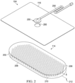
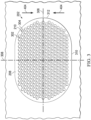
- Figure 3 is a plan view, illustrating additional details that may be associated with some embodiments of the contact layer 202.
- the holes 210 can be distributed about the second surface 208 of the contact layer 202.
- the holes 210 can be evenly distributed.
- the holes 210 may be preferentially disposed in a portion of the contact layer 202.
- the contact layer 202 may include the plurality of holes 210 or other perforations extending into the contact layer 202 to form walls 302.
- an exterior surface of the walls 302 may be parallel to sides of the contact layer 202.
- an interior surface of the walls 302 may be generally perpendicular to the second surface 208 of the contact layer 202.
- the exterior surface or surfaces of the walls 302 may be coincident with the second surface 208.
- the interior surface or surfaces of the walls 302 may form a perimeter 304 of each hole 210.
- the holes 210 may have a circular shape as shown.
- the holes 210 may have average effective diameters between about 5 mm and about 20 mm, and in some embodiments, the average effective diameters of the holes 210 may be about 10 mm.
- the contact layer 202 may be placed at the tissue site so that the second orientation line 308 extends across debris located at the tissue site.
- the contact layer 202 is shown as having a generally ovoid shape including longitudinal edges 310 and circular edges 312, the contact layer 202 may have other shapes.
- the contact layer 202 may have a rectangular, diamond, square, circular, triangular, or amorphous shape.
- the shape of the contact layer 202 may be selected to accommodate the type of tissue site being treated.
- the contact layer 202 may have an oval or circular shape to accommodate an oval or circular tissue site.
- the contact layer 202 may be sizeable.
- the contact layer 202 may be cut, torn, or otherwise separated into portions to permit the contact layer 202 to be diminished in size for smaller tissue sites.
- the first orientation line 306 may be parallel to the longitudinal edges 310.
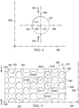
- FIG 4 is a plan view illustrating additional details that may be associated with some embodiments of a hole 210 of Figure 3 .
- a single hole 210 having a circular shape is shown.
- the hole 210 may include a center 402 and the perimeter 304.
- the hole 210 may have a perforation shape factor (PSF).
- the perforation shape factor (PSF) may represent an orientation of the hole 210 relative to the first orientation line 306 and the second orientation line 308.
- the perforation shape factor (PSF) is a ratio of 1 ⁇ 2 a maximum length of the hole 210 that is parallel to the desired direction of contraction to 1 ⁇ 2 a maximum length of the hole 210 that is perpendicular to the desired direction of contraction.
- the centers 402 of the holes 210 in adjacent rows may be characterized by being offset from the second orientation line 308 along the first orientation line 306.
- a line connecting the centers of adjacent rows may form a strut angle (SA) with the first orientation line 306.
- SA strut angle
- a first hole 210A in the first row 502 may have a center 402A
- a second hole 210B in the second row 504 may have a center 402B.
- a strut line 508 may connect the center 402A with the center 402B.
- the strut line 508 may form an angle 510 with the first orientation line 306.
- the angle 510 may be the strut angle (SA) of the contact layer 202.
- the strut angle (SA) may be less than about 90°. In other embodiments, the strut angle (SA) may be between about 30° and about 70° relative to the first orientation line 306. In other embodiments, the strut angle (SA) may be about 66° from the first orientation line 306. Generally, as the strut angle (SA) decreases, a stiffness of the contact layer 202 in a direction parallel to the first orientation line 306 may increase. Increasing the stiffness of the contact layer 202 parallel to the first orientation line 306 may increase the compressibility of the contact layer 202 perpendicular to the first orientation line 306.
- the contact layer 202 may be more compliant or compressible in a direction perpendicular to the first orientation line 306.
- the contact layer 202 may collapse to apply the lateral force 404 to the tissue site as described in more detail below.
- the centers 402 of the holes 210 in alternating rows may be spaced from each other parallel to the second orientation line 308 by a length 512.
- the length 512 may be greater than an effective diameter of the hole 210. If the centers 402 of holes 210 in alternating rows are separated by the length 512, the exterior surface of the walls 302 parallel to the first orientation line 306 may be considered continuous. Generally, the exterior surface of the walls 302 may be continuous if the exterior surface of the walls 302 do not have any discontinuities or breaks between holes 210.
- the length 512 may be between about 7 mm and about 25 mm.
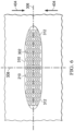
- Figure 6 is a plan view illustrating additional details of the contact layer 202 of Figure 3 in a contracted state. If the contact layer 202 is positioned on the tissue site, the contact layer 202 may generate the lateral force 404 along the second orientation line 308, contracting the contact layer 202, as shown in more detail in Figure 6 .
- the holes 210 may be circular, have a strut angle (SA) of approximately 37°, a void space percentage (VS) of about 54%, a firmness factor (FF) of about 5, a perforation shape factor (PSF) of about 1, and a diameter of about 5 mm.
- SA strut angle
- VS void space percentage
- FF firmness factor
- PSF perforation shape factor
- the formulas described above may not precisely describe the lateral forces due to losses in force due to the transfer of the force from the contact layer to the wound.
- the modulus and stretching of the cover 116, the modulus of the tissue site, slippage of the cover 116 over the tissue site, and friction between the contact layer 202 and the tissue site may cause the actual value of the lateral force 404 to be less than the calculated value of the lateral force 404.
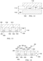
- the projections 1108 can be heated to a temperature between 60 °C and 100 °C and, preferably, about 80 °C. Pressing of the projections 1108 into the block 1002 while the surface 1106 of the mandrel 1104 is adjacent to the second surface 208 can create zones of localized felting of the block 1002.
- the zones of localized felting of the block 1002 can cause localized portions 1302 of the block 1002 to be felted to a second level forming voids in the block 1002.
- the second level can increase the density of the block 1002 at the localized portions 1302 to about five times the density of the block 1002 after the first felting process and about seven times the density of the dressing material of the block 1002 prior to the first felting process.
- the localized portions 1302 of the block 1002 may have a thickness 1304 that is less than the second thickness 1102 of the block 1002. In some embodiments, the thickness 1304 may be between about 2 mm and about 5 mm.
- Figure 14 is a sectional view of the operational step in the process for manufacturing the contact layer 202 taken along line 12-12 of Figure 11 , illustrating additional details that may be associated with some embodiments.
- the mandrel 1104 can be removed from the block 1002.
- the second felting process can form the holes 210 at the localized portions 1302.
- the holes 210 may have a depth approximately equal to the eight 1110 of the projections 1108.
- the second felting process can form a transition zone 1402 between the holes 210 and the second surface 208.
- the transition zone 1402 can comprise a large radii at the perimeters 304 of the holes 210 where the second surface 208 intersects the walls 302.
Landscapes
- Health & Medical Sciences (AREA)
- Engineering & Computer Science (AREA)
- Biomedical Technology (AREA)
- Heart & Thoracic Surgery (AREA)
- Vascular Medicine (AREA)
- Life Sciences & Earth Sciences (AREA)
- Animal Behavior & Ethology (AREA)
- General Health & Medical Sciences (AREA)
- Public Health (AREA)
- Veterinary Medicine (AREA)
- Dermatology (AREA)
- Media Introduction/Drainage Providing Device (AREA)
Claims (8)
- Ein Verband zur Behandlung einer Gewebestelle, wobei der Verband eine Gewebeschnittstelle (202) umfasst, die aufweist:eine erste Seite (208), eine zweite Seite (206) und eine erste Dicke (212, 1102) von der ersten Seite (208) zu der zweiten Seite (206);eine Vielzahl von Blindöffnungen (210), die in der ersten Seite (208) angeordnet sind, wobei jede der Blindöffnungen eine zweite Dicke (1304) von der ersten Seite zu der zweiten Seite (206) aufweist; undwobei die Gewebeschnittstelle eine erste Dichte bei der ersten Dicke (212, 1102) und eine zweite Dichte bei der zweiten Dicke (1304) aufweist;wobei die zweite Dicke (1304) geringer ist als die erste Dicke (212, 1102) und die zweite Dichte höher ist als die erste Dichte.
- Der Verband nach Anspruch 1, wobei die zweite Dichte fünfmal größer ist als die erste Dichte.
- Der Verband nach Anspruch 16, wobei die erste Dicke etwa 10 mm beträgt.
- Der Verband nach Anspruch 16, wobei die zweite Dicke zwischen etwa 2 mm und etwa 4 mm beträgt.
- Der Verband nach Anspruch 16, der ferner Übergangszonen (1402) zwischen der ersten Dicke (212, 1102) und der zweiten Dicke (1304) aufweist.
- Der Verband nach Anspruch 22, wobei die Übergangszonen (1402) große Radien aufweisen.
- Der Verband nach Anspruch 16, wobei die Gewebegrenzfläche einen offenzelligen retikulierten Schaumstoff umfasst.
- Ein System zum Bereitstellen einer Unterdrucktherapie an einer Gewebestelle, wobei das System aufweist:eine Gewebegrenzfläche nach einem der vorstehenden Ansprüche;ein Dichtungselement, das so konfiguriert ist, dass es über der Gewebegrenzfläche angeordnet wird, um einen abgedichteten Raum zu erzeugen; und eine Unterdruckquelle, die so konfiguriert ist, dass sie mit dem abgedichteten Raum in Fluidverbindung steht.
Applications Claiming Priority (2)
| Application Number | Priority Date | Filing Date | Title |
|---|---|---|---|
| US202063020361P | 2020-05-05 | 2020-05-05 | |
| PCT/IB2021/053133 WO2021224698A1 (en) | 2020-05-05 | 2021-04-15 | Tissue interface for negative pressure and instillation therapy |
Publications (2)
| Publication Number | Publication Date |
|---|---|
| EP4132440A1 EP4132440A1 (de) | 2023-02-15 |
| EP4132440B1 true EP4132440B1 (de) | 2024-07-10 |
Family
ID=75639938
Family Applications (1)
| Application Number | Title | Priority Date | Filing Date |
|---|---|---|---|
| EP21720845.3A Active EP4132440B1 (de) | 2020-05-05 | 2021-04-15 | Gewebeschnittstelle für unterdruck- und instillationstherapie |
Country Status (3)
| Country | Link |
|---|---|
| US (1) | US20230190530A1 (de) |
| EP (1) | EP4132440B1 (de) |
| WO (1) | WO2021224698A1 (de) |
Family Cites Families (6)
| Publication number | Priority date | Publication date | Assignee | Title |
|---|---|---|---|---|
| US3977406A (en) * | 1974-06-19 | 1976-08-31 | American Cyanamid Company | Medical sponges |
| WO2004047695A1 (en) * | 2002-11-26 | 2004-06-10 | Coloplast A/S | A dressing |
| US7951124B2 (en) * | 2004-04-13 | 2011-05-31 | Boehringer Technologies, Lp | Growth stimulating wound dressing with improved contact surfaces |
| ES2625463T3 (es) * | 2007-05-24 | 2017-07-19 | Applied Tissue Technologies Llc | Dispositivo para tratamiento de heridas que emplea presión negativa |
| EP3791837B1 (de) * | 2014-05-09 | 2024-07-17 | Solventum Intellectual Properties Company | Ablösungsverband zur verwendung mit unterdruck- und fluidinstillation |
| EP3836872A1 (de) * | 2018-08-13 | 2021-06-23 | KCI Licensing, Inc. | Ablösungsverband zur verwendung mit unterdruck- und fluidinstillation |
-
2021
- 2021-04-15 WO PCT/IB2021/053133 patent/WO2021224698A1/en not_active Ceased
- 2021-04-15 US US17/916,219 patent/US20230190530A1/en active Pending
- 2021-04-15 EP EP21720845.3A patent/EP4132440B1/de active Active
Also Published As
| Publication number | Publication date |
|---|---|
| WO2021224698A1 (en) | 2021-11-11 |
| EP4132440A1 (de) | 2023-02-15 |
| US20230190530A1 (en) | 2023-06-22 |
Similar Documents
| Publication | Publication Date | Title |
|---|---|---|
| US20250352397A1 (en) | Wound dressing with semi-rigid support to increase disruption using perforated dressing and negative pressure wound therapy | |
| AU2020203649B2 (en) | Disruptive dressing for use with negative pressure and fluid instillation | |
| US20200046567A1 (en) | Disruptive dressing for use with negative pressure and fluid instillation | |
| EP4069170B1 (de) | Gewebeschnittstelle für unterdruck- und instillationstherapie | |
| CA2947298C (en) | Debriding dressing for use with negative pressure and fluid instillation | |
| US20230000687A1 (en) | Tissue interface for negative-pressure and instillation therapy | |
| US20200237562A1 (en) | Variable density dressing | |
| US20190240073A1 (en) | Dressing for disruption of debris at a tissue site | |
| EP4007550B1 (de) | Antimikrobieller/antibakterieller verband mit zerstörender wirkung zur verwendung mit unterdruck und flüssigkeitsinstillation | |
| EP4132440B1 (de) | Gewebeschnittstelle für unterdruck- und instillationstherapie | |
| US20230301835A1 (en) | Low-growth tissue interface | |
| EP4164567B1 (de) | Gewebeschnittstelle für gewebedebridement | |
| WO2021140468A1 (en) | Systems and apparatuses for wound cleansing and tissue deformation | |
| US20230404812A1 (en) | Extended wear dressing with slough cleaning holes |
Legal Events
| Date | Code | Title | Description |
|---|---|---|---|
| STAA | Information on the status of an ep patent application or granted ep patent |
Free format text: STATUS: UNKNOWN |
|
| STAA | Information on the status of an ep patent application or granted ep patent |
Free format text: STATUS: THE INTERNATIONAL PUBLICATION HAS BEEN MADE |
|
| PUAI | Public reference made under article 153(3) epc to a published international application that has entered the european phase |
Free format text: ORIGINAL CODE: 0009012 |
|
| STAA | Information on the status of an ep patent application or granted ep patent |
Free format text: STATUS: REQUEST FOR EXAMINATION WAS MADE |
|
| 17P | Request for examination filed |
Effective date: 20221110 |
|
| AK | Designated contracting states |
Kind code of ref document: A1 Designated state(s): AL AT BE BG CH CY CZ DE DK EE ES FI FR GB GR HR HU IE IS IT LI LT LU LV MC MK MT NL NO PL PT RO RS SE SI SK SM TR |
|
| DAV | Request for validation of the european patent (deleted) | ||
| DAX | Request for extension of the european patent (deleted) | ||
| RAP1 | Party data changed (applicant data changed or rights of an application transferred) |
Owner name: KCI MANUFACTURING UNLIMITED COMPANY |
|
| GRAP | Despatch of communication of intention to grant a patent |
Free format text: ORIGINAL CODE: EPIDOSNIGR1 |
|
| STAA | Information on the status of an ep patent application or granted ep patent |
Free format text: STATUS: GRANT OF PATENT IS INTENDED |
|
| INTG | Intention to grant announced |
Effective date: 20240418 |
|
| GRAS | Grant fee paid |
Free format text: ORIGINAL CODE: EPIDOSNIGR3 |
|
| GRAA | (expected) grant |
Free format text: ORIGINAL CODE: 0009210 |
|
| STAA | Information on the status of an ep patent application or granted ep patent |
Free format text: STATUS: THE PATENT HAS BEEN GRANTED |
|
| AK | Designated contracting states |
Kind code of ref document: B1 Designated state(s): AL AT BE BG CH CY CZ DE DK EE ES FI FR GB GR HR HU IE IS IT LI LT LU LV MC MK MT NL NO PL PT RO RS SE SI SK SM TR |
|
| REG | Reference to a national code |
Ref country code: CH Ref legal event code: EP |
|
| REG | Reference to a national code |
Ref country code: DE Ref legal event code: R096 Ref document number: 602021015482 Country of ref document: DE |
|
| REG | Reference to a national code |
Ref country code: LT Ref legal event code: MG9D |
|
| REG | Reference to a national code |
Ref country code: NL Ref legal event code: MP Effective date: 20240710 |
|
| PG25 | Lapsed in a contracting state [announced via postgrant information from national office to epo] |
Ref country code: PT Free format text: LAPSE BECAUSE OF FAILURE TO SUBMIT A TRANSLATION OF THE DESCRIPTION OR TO PAY THE FEE WITHIN THE PRESCRIBED TIME-LIMIT Effective date: 20241111 |
|
| REG | Reference to a national code |
Ref country code: AT Ref legal event code: MK05 Ref document number: 1701401 Country of ref document: AT Kind code of ref document: T Effective date: 20240710 |
|
| PG25 | Lapsed in a contracting state [announced via postgrant information from national office to epo] |
Ref country code: NL Free format text: LAPSE BECAUSE OF FAILURE TO SUBMIT A TRANSLATION OF THE DESCRIPTION OR TO PAY THE FEE WITHIN THE PRESCRIBED TIME-LIMIT Effective date: 20240710 |
|
| PG25 | Lapsed in a contracting state [announced via postgrant information from national office to epo] |
Ref country code: PT Free format text: LAPSE BECAUSE OF FAILURE TO SUBMIT A TRANSLATION OF THE DESCRIPTION OR TO PAY THE FEE WITHIN THE PRESCRIBED TIME-LIMIT Effective date: 20241111 Ref country code: NL Free format text: LAPSE BECAUSE OF FAILURE TO SUBMIT A TRANSLATION OF THE DESCRIPTION OR TO PAY THE FEE WITHIN THE PRESCRIBED TIME-LIMIT Effective date: 20240710 |
|
| PG25 | Lapsed in a contracting state [announced via postgrant information from national office to epo] |
Ref country code: NO Free format text: LAPSE BECAUSE OF FAILURE TO SUBMIT A TRANSLATION OF THE DESCRIPTION OR TO PAY THE FEE WITHIN THE PRESCRIBED TIME-LIMIT Effective date: 20241010 |
|
| PG25 | Lapsed in a contracting state [announced via postgrant information from national office to epo] |
Ref country code: FI Free format text: LAPSE BECAUSE OF FAILURE TO SUBMIT A TRANSLATION OF THE DESCRIPTION OR TO PAY THE FEE WITHIN THE PRESCRIBED TIME-LIMIT Effective date: 20240710 Ref country code: GR Free format text: LAPSE BECAUSE OF FAILURE TO SUBMIT A TRANSLATION OF THE DESCRIPTION OR TO PAY THE FEE WITHIN THE PRESCRIBED TIME-LIMIT Effective date: 20241011 Ref country code: PL Free format text: LAPSE BECAUSE OF FAILURE TO SUBMIT A TRANSLATION OF THE DESCRIPTION OR TO PAY THE FEE WITHIN THE PRESCRIBED TIME-LIMIT Effective date: 20240710 |
|
| PG25 | Lapsed in a contracting state [announced via postgrant information from national office to epo] |
Ref country code: BG Free format text: LAPSE BECAUSE OF FAILURE TO SUBMIT A TRANSLATION OF THE DESCRIPTION OR TO PAY THE FEE WITHIN THE PRESCRIBED TIME-LIMIT Effective date: 20240710 |
|
| PG25 | Lapsed in a contracting state [announced via postgrant information from national office to epo] |
Ref country code: LV Free format text: LAPSE BECAUSE OF FAILURE TO SUBMIT A TRANSLATION OF THE DESCRIPTION OR TO PAY THE FEE WITHIN THE PRESCRIBED TIME-LIMIT Effective date: 20240710 |
|
| PG25 | Lapsed in a contracting state [announced via postgrant information from national office to epo] |
Ref country code: AT Free format text: LAPSE BECAUSE OF FAILURE TO SUBMIT A TRANSLATION OF THE DESCRIPTION OR TO PAY THE FEE WITHIN THE PRESCRIBED TIME-LIMIT Effective date: 20240710 Ref country code: IS Free format text: LAPSE BECAUSE OF FAILURE TO SUBMIT A TRANSLATION OF THE DESCRIPTION OR TO PAY THE FEE WITHIN THE PRESCRIBED TIME-LIMIT Effective date: 20241110 |
|
| PG25 | Lapsed in a contracting state [announced via postgrant information from national office to epo] |
Ref country code: HR Free format text: LAPSE BECAUSE OF FAILURE TO SUBMIT A TRANSLATION OF THE DESCRIPTION OR TO PAY THE FEE WITHIN THE PRESCRIBED TIME-LIMIT Effective date: 20240710 |
|
| PG25 | Lapsed in a contracting state [announced via postgrant information from national office to epo] |
Ref country code: ES Free format text: LAPSE BECAUSE OF FAILURE TO SUBMIT A TRANSLATION OF THE DESCRIPTION OR TO PAY THE FEE WITHIN THE PRESCRIBED TIME-LIMIT Effective date: 20240710 Ref country code: RS Free format text: LAPSE BECAUSE OF FAILURE TO SUBMIT A TRANSLATION OF THE DESCRIPTION OR TO PAY THE FEE WITHIN THE PRESCRIBED TIME-LIMIT Effective date: 20241010 |
|
| PG25 | Lapsed in a contracting state [announced via postgrant information from national office to epo] |
Ref country code: RS Free format text: LAPSE BECAUSE OF FAILURE TO SUBMIT A TRANSLATION OF THE DESCRIPTION OR TO PAY THE FEE WITHIN THE PRESCRIBED TIME-LIMIT Effective date: 20241010 Ref country code: PL Free format text: LAPSE BECAUSE OF FAILURE TO SUBMIT A TRANSLATION OF THE DESCRIPTION OR TO PAY THE FEE WITHIN THE PRESCRIBED TIME-LIMIT Effective date: 20240710 Ref country code: NO Free format text: LAPSE BECAUSE OF FAILURE TO SUBMIT A TRANSLATION OF THE DESCRIPTION OR TO PAY THE FEE WITHIN THE PRESCRIBED TIME-LIMIT Effective date: 20241010 Ref country code: LV Free format text: LAPSE BECAUSE OF FAILURE TO SUBMIT A TRANSLATION OF THE DESCRIPTION OR TO PAY THE FEE WITHIN THE PRESCRIBED TIME-LIMIT Effective date: 20240710 Ref country code: IS Free format text: LAPSE BECAUSE OF FAILURE TO SUBMIT A TRANSLATION OF THE DESCRIPTION OR TO PAY THE FEE WITHIN THE PRESCRIBED TIME-LIMIT Effective date: 20241110 Ref country code: HR Free format text: LAPSE BECAUSE OF FAILURE TO SUBMIT A TRANSLATION OF THE DESCRIPTION OR TO PAY THE FEE WITHIN THE PRESCRIBED TIME-LIMIT Effective date: 20240710 Ref country code: GR Free format text: LAPSE BECAUSE OF FAILURE TO SUBMIT A TRANSLATION OF THE DESCRIPTION OR TO PAY THE FEE WITHIN THE PRESCRIBED TIME-LIMIT Effective date: 20241011 Ref country code: FI Free format text: LAPSE BECAUSE OF FAILURE TO SUBMIT A TRANSLATION OF THE DESCRIPTION OR TO PAY THE FEE WITHIN THE PRESCRIBED TIME-LIMIT Effective date: 20240710 Ref country code: ES Free format text: LAPSE BECAUSE OF FAILURE TO SUBMIT A TRANSLATION OF THE DESCRIPTION OR TO PAY THE FEE WITHIN THE PRESCRIBED TIME-LIMIT Effective date: 20240710 Ref country code: BG Free format text: LAPSE BECAUSE OF FAILURE TO SUBMIT A TRANSLATION OF THE DESCRIPTION OR TO PAY THE FEE WITHIN THE PRESCRIBED TIME-LIMIT Effective date: 20240710 Ref country code: AT Free format text: LAPSE BECAUSE OF FAILURE TO SUBMIT A TRANSLATION OF THE DESCRIPTION OR TO PAY THE FEE WITHIN THE PRESCRIBED TIME-LIMIT Effective date: 20240710 |
|
| REG | Reference to a national code |
Ref country code: DE Ref legal event code: R097 Ref document number: 602021015482 Country of ref document: DE |
|
| PG25 | Lapsed in a contracting state [announced via postgrant information from national office to epo] |
Ref country code: DK Free format text: LAPSE BECAUSE OF FAILURE TO SUBMIT A TRANSLATION OF THE DESCRIPTION OR TO PAY THE FEE WITHIN THE PRESCRIBED TIME-LIMIT Effective date: 20240710 Ref country code: SM Free format text: LAPSE BECAUSE OF FAILURE TO SUBMIT A TRANSLATION OF THE DESCRIPTION OR TO PAY THE FEE WITHIN THE PRESCRIBED TIME-LIMIT Effective date: 20240710 Ref country code: RO Free format text: LAPSE BECAUSE OF FAILURE TO SUBMIT A TRANSLATION OF THE DESCRIPTION OR TO PAY THE FEE WITHIN THE PRESCRIBED TIME-LIMIT Effective date: 20240710 |
|
| PG25 | Lapsed in a contracting state [announced via postgrant information from national office to epo] |
Ref country code: EE Free format text: LAPSE BECAUSE OF FAILURE TO SUBMIT A TRANSLATION OF THE DESCRIPTION OR TO PAY THE FEE WITHIN THE PRESCRIBED TIME-LIMIT Effective date: 20240710 |
|
| PG25 | Lapsed in a contracting state [announced via postgrant information from national office to epo] |
Ref country code: CZ Free format text: LAPSE BECAUSE OF FAILURE TO SUBMIT A TRANSLATION OF THE DESCRIPTION OR TO PAY THE FEE WITHIN THE PRESCRIBED TIME-LIMIT Effective date: 20240710 |
|
| PG25 | Lapsed in a contracting state [announced via postgrant information from national office to epo] |
Ref country code: IT Free format text: LAPSE BECAUSE OF FAILURE TO SUBMIT A TRANSLATION OF THE DESCRIPTION OR TO PAY THE FEE WITHIN THE PRESCRIBED TIME-LIMIT Effective date: 20240710 Ref country code: SK Free format text: LAPSE BECAUSE OF FAILURE TO SUBMIT A TRANSLATION OF THE DESCRIPTION OR TO PAY THE FEE WITHIN THE PRESCRIBED TIME-LIMIT Effective date: 20240710 |
|
| PGFP | Annual fee paid to national office [announced via postgrant information from national office to epo] |
Ref country code: GB Payment date: 20250319 Year of fee payment: 5 |
|
| PLBE | No opposition filed within time limit |
Free format text: ORIGINAL CODE: 0009261 |
|
| STAA | Information on the status of an ep patent application or granted ep patent |
Free format text: STATUS: NO OPPOSITION FILED WITHIN TIME LIMIT |
|
| 26N | No opposition filed |
Effective date: 20250411 |
|
| PGFP | Annual fee paid to national office [announced via postgrant information from national office to epo] |
Ref country code: DE Payment date: 20250319 Year of fee payment: 5 |
|
| PG25 | Lapsed in a contracting state [announced via postgrant information from national office to epo] |
Ref country code: SE Free format text: LAPSE BECAUSE OF FAILURE TO SUBMIT A TRANSLATION OF THE DESCRIPTION OR TO PAY THE FEE WITHIN THE PRESCRIBED TIME-LIMIT Effective date: 20240710 |
|
| REG | Reference to a national code |
Ref country code: CH Ref legal event code: H13 Free format text: ST27 STATUS EVENT CODE: U-0-0-H10-H13 (AS PROVIDED BY THE NATIONAL OFFICE) Effective date: 20251125 |
|
| PG25 | Lapsed in a contracting state [announced via postgrant information from national office to epo] |
Ref country code: LU Free format text: LAPSE BECAUSE OF NON-PAYMENT OF DUE FEES Effective date: 20250415 |