EP4132015A1 - Verfahren und vorrichtung zum bestimmen der ankunftszeit, signalempfangsvorrichtung und speichermedium - Google Patents
Verfahren und vorrichtung zum bestimmen der ankunftszeit, signalempfangsvorrichtung und speichermedium Download PDFInfo
- Publication number
- EP4132015A1 EP4132015A1 EP20928105.4A EP20928105A EP4132015A1 EP 4132015 A1 EP4132015 A1 EP 4132015A1 EP 20928105 A EP20928105 A EP 20928105A EP 4132015 A1 EP4132015 A1 EP 4132015A1
- Authority
- EP
- European Patent Office
- Prior art keywords
- arrival
- time
- front edge
- correction information
- slope
- Prior art date
- Legal status (The legal status is an assumption and is not a legal conclusion. Google has not performed a legal analysis and makes no representation as to the accuracy of the status listed.)
- Pending
Links
Images


Classifications
-
- H—ELECTRICITY
- H04—ELECTRIC COMMUNICATION TECHNIQUE
- H04W—WIRELESS COMMUNICATION NETWORKS
- H04W4/00—Services specially adapted for wireless communication networks; Facilities therefor
- H04W4/02—Services making use of location information
-
- G—PHYSICS
- G01—MEASURING; TESTING
- G01S—RADIO DIRECTION-FINDING; RADIO NAVIGATION; DETERMINING DISTANCE OR VELOCITY BY USE OF RADIO WAVES; LOCATING OR PRESENCE-DETECTING BY USE OF THE REFLECTION OR RERADIATION OF RADIO WAVES; ANALOGOUS ARRANGEMENTS USING OTHER WAVES
- G01S5/00—Position-fixing by co-ordinating two or more direction or position line determinations; Position-fixing by co-ordinating two or more distance determinations
- G01S5/02—Position-fixing by co-ordinating two or more direction or position line determinations; Position-fixing by co-ordinating two or more distance determinations using radio waves
- G01S5/0205—Details
- G01S5/0218—Multipath in signal reception
-
- G—PHYSICS
- G01—MEASURING; TESTING
- G01S—RADIO DIRECTION-FINDING; RADIO NAVIGATION; DETERMINING DISTANCE OR VELOCITY BY USE OF RADIO WAVES; LOCATING OR PRESENCE-DETECTING BY USE OF THE REFLECTION OR RERADIATION OF RADIO WAVES; ANALOGOUS ARRANGEMENTS USING OTHER WAVES
- G01S5/00—Position-fixing by co-ordinating two or more direction or position line determinations; Position-fixing by co-ordinating two or more distance determinations
- G01S5/02—Position-fixing by co-ordinating two or more direction or position line determinations; Position-fixing by co-ordinating two or more distance determinations using radio waves
- G01S5/0205—Details
- G01S5/0221—Receivers
-
- H—ELECTRICITY
- H04—ELECTRIC COMMUNICATION TECHNIQUE
- H04W—WIRELESS COMMUNICATION NETWORKS
- H04W64/00—Locating users or terminals or network equipment for network management purposes, e.g. mobility management
-
- G—PHYSICS
- G01—MEASURING; TESTING
- G01S—RADIO DIRECTION-FINDING; RADIO NAVIGATION; DETERMINING DISTANCE OR VELOCITY BY USE OF RADIO WAVES; LOCATING OR PRESENCE-DETECTING BY USE OF THE REFLECTION OR RERADIATION OF RADIO WAVES; ANALOGOUS ARRANGEMENTS USING OTHER WAVES
- G01S11/00—Systems for determining distance or velocity not using reflection or reradiation
- G01S11/02—Systems for determining distance or velocity not using reflection or reradiation using radio waves
-
- G—PHYSICS
- G01—MEASURING; TESTING
- G01S—RADIO DIRECTION-FINDING; RADIO NAVIGATION; DETERMINING DISTANCE OR VELOCITY BY USE OF RADIO WAVES; LOCATING OR PRESENCE-DETECTING BY USE OF THE REFLECTION OR RERADIATION OF RADIO WAVES; ANALOGOUS ARRANGEMENTS USING OTHER WAVES
- G01S5/00—Position-fixing by co-ordinating two or more direction or position line determinations; Position-fixing by co-ordinating two or more distance determinations
- G01S5/02—Position-fixing by co-ordinating two or more direction or position line determinations; Position-fixing by co-ordinating two or more distance determinations using radio waves
- G01S5/06—Position of source determined by co-ordinating a plurality of position lines defined by path-difference measurements
Definitions
- the present disclosure relates to the field of wireless communication systems, for example, to a method and an apparatus for determining time of arrival, a signal receiving device, and a storage medium.
- a time difference of arrival (TDOA) positioning method is generally used for high-precision positioning of a device in a communication network, that is, a distance between a sender and a receiver is determined by measuring the time when a signal arrives at the receiver, and according to distances from a signal source to various receivers, the position of the signal source can be determined.
- the TDOA positioning method mainly includes: determining a frame header and defining orthogonal frequency division multiplexing (OFDM) symbols. Starting from a defined time point, a fixed number of sampling points are removed according to a prefix length to obtain time domain data for the symbols. Then, a mathematical sequence correlation operation is performed, and the first maximum correlation peak is taken as the time of arrival of a signal.
- OFDM orthogonal frequency division multiplexing
- the detection of TOA is usually based on a theoretical autocorrelation triangular waveform of a signal.
- the slope of a signal correlation waveform is distorted, which is no longer an ideal triangular waveform. Therefore, there is a very large error in a slope-based detection method.
- the bandwidth is limited, and in the case where the bandwidth is strictly limited, the autocorrelation waveform is no longer a strict triangular waveform. This situation, together with a multipath situation, makes the signal correlation waveform more complicated, such that the precision and reliability of the slope-based detection method are relatively low.
- Embodiments of the present disclosure provide a method and an apparatus for determining time of arrival, a signal receiving device and a storage medium, to improve the precision and reliability of detection of the time of arrival.
- a method for determining time of arrival includes: generating time of arrival correction information according to front edge information of theoretical autocorrelation waveforms of positioning signals having different fading values; calculating a front edge slope corresponding to a front edge reference point of a correlation waveform of an actually received signal; and determining target correction information from the time of arrival correction information according to the front edge slope, and determining the time of arrival of the actually received signal based on the target correction information.
- an apparatus for determining time of arrival includes: a correction information generation module configured to generate time of arrival correction information according to front edge information of theoretical autocorrelation waveforms of positioning signals having different fading values; a front edge slope calculation module configured to calculate a front edge slope corresponding to a front edge reference point of a correlation waveform of an actually received signal; and a time of arrival determination module configured to determine target correction information from the time of arrival correction information according to the front edge slope, and determine the time of arrival of the actually received signal based on the target correction information.
- the signal receiving device includes: one or more processors; and a storage means configured to store one or more programs which, when executed by the one or more processors, cause the one or more processors to carry out the method for determining time of arrival described above.
- a computer-readable storage medium storing computer programs which, when executed by a processor, cause the processor to carry out the method for determining time of arrival described above.
- time of arrival of a signal When locating a device in a wireless communication network, it is necessary to detect time of arrival of a signal.
- the detection of the time of arrival is usually based on slope detection of a theoretical autocorrelation triangular waveform of the signal. For example, a time for the first maximum correlation peak is taken as the time of arrival of the signal.
- the slope of a signal correlation waveform is often distorted.
- FIG. 1 is a schematic diagram of an actually received signal in multipath transmission.
- the multipath transmission of a signal is taken as an example, in which dotted lines represent results of multipath transmission of the signal, and a solid line represents a waveform of a signal actually received by a receiving end.
- the correlation waveform of the actually received signal is obviously not an ideal triangular waveform, so the method based on slope detection to determine the time of arrival of the signal has a very large error.
- the slope detection method may have a large error due to an unstable channel quality and an influence of other noise or a bandwidth limitation, which makes it impossible to achieve high-precision measurement of the time of arrival in a complex wireless environment and under a bandwidth limitation.
- time of arrival correction information is generated according to theoretical autocorrelation waveforms of positioning signals, and the moments for some front edge positions of an actually received signal are corrected according to theoretical time of arrival correction information.
- time of arrival correction information is generated according to theoretical autocorrelation waveforms of positioning signals, and the moments for some front edge positions of an actually received signal are corrected according to theoretical time of arrival correction information.
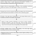
- FIG. 2 is a flowchart of a method for determining time of arrival provided by an embodiment. As shown in FIG. 2 , the method provided in this embodiment includes steps S110 to S140.
- time of arrival correction information is generated according to front edge information of theoretical autocorrelation waveforms of positioning signals having different fading values.
- a front edge slope corresponding to a front edge reference point of a correlation waveform of an actually received signal is calculated.
- target correction information is determined from the time of arrival correction information according to the front edge slope.
- the time of arrival of the actually received signal is determined based on the target correction information.
- the time of arrival correction information is generated with the front edge information of the theoretical autocorrelation waveforms of the positioning signals.
- the theoretical autocorrelation waveforms of the positioning signals corresponding to different fading values are divided into several segments, and several reference points on the front edges of the theoretical autocorrelation waves can be determined according to the division results.
- Time of arrival correction information can be generated according to the moments corresponding to the reference points.
- the time of arrival correction information may be stored in the form of a table. Each entry of the time of arrival correction information corresponds to a reference point, which records the front edge information of the reference point.
- the front edge information may include the slope, the moment, etc.
- the time of arrival correction information generated according to the theoretical autocorrelation waveforms accords with a transmission result of a signal in an ideal state.
- target correction information at a position corresponding to the front edge reference point is found in the time of arrival correction information, by which the moment of the front edge reference point of the actually received signal is corrected.
- the earliest moment in the corresponding corrected moments of the front edge reference points (which may also be a moment average obtained through a mathematical statistical operation based on several earliest moments or a class of earliest moments, etc.) can be taken as the time of arrival, thereby reducing the error in detecting the time of arrival of the actually received signal based on the slope.
- the fading values of the positioning signals can be divided into several different values, so as to obtain positioning signals corresponding to different fading values.
- the maximum fading value is 1.
- the fading values are divided into 3 types. Taking trisection of the fading values as an example, the fading values of the positioning signals are 1, 2/3, 1/3 respectively, so that theoretical autocorrelation waveforms of three positioning signals are obtained.
- the theoretical autocorrelation waveform of each positioning signal may also be divided into several segments according to a certain rule, so as to determine several reference points of the front edge. Time of arrival correction information is generated according to the slope and the moment corresponding to each reference point.
- the correlation waveform of an actually received signal may be divided into several segments according to the same rule to obtain several corresponding front edge reference points. According to the front edge slope of each front edge reference point, an entry closest to the front edge slope is determined from the time of arrival correction information, which is the target correction information corresponding to the front reference point.
- the theoretical autocorrelation waveforms of the positioning signals are normalized according to moduli or the fading values, and the correlation waveform of the actually received signal is normalized according to a modulus, thereby facilitating selection of reference points and reducing the amount of calculation.
- time of arrival correction information is generated according to theoretical autocorrelation waveforms of positioning signals, and a front edge reference point of an actually received signal is corrected according to theoretical time of arrival correction information, and the time of arrival is determined based on corrected data of a correlation waveform of the actually received signal.
- FIG. 3 is a flowchart of another method for determining time of arrival provided by an embodiment. As shown in FIG. 3 , the method provided in this embodiment includes steps S210 to S270.
- fading values of autocorrelation waveforms of normalized positioning signals are equally divided into n parts to obtain theoretical autocorrelation waveforms of n positioning signals corresponding to different fading values.
- the front edge heights of the autocorrelation waveforms of the normalized positioning signals are equally divided into m parts to obtain m first bisectrices.
- time of arrival correction information is generated according to the m first bisectrices and the theoretical autocorrelation waveforms of the n positioning signals.
- the positioning signals are normalized according to the moduli, that is, the maximum modulus is 1.
- Equally dividing the fading values of the autocorrelation waveforms of the normalized positioning signals into n parts refers to dividing the autocorrelation waveforms of the normalized positioning signals into n types, which are sequentially as follows: the maximum modulus of an autocorrelation function is 1, the maximum modulus of an autocorrelation function is ( n -1)/ n, ... , and the maximum modulus of an autocorrelation function is 1/ n . There are a total of n positioning signals corresponding to different fading values.
- the front edge heights of the autocorrelation waveforms of the normalized positioning signals are equally divided into m parts from 0 to 1 to obtain m first bisectrices, and the height of each part is 1/ m.
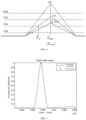
- FIG. 4 is a schematic diagram of m first bisectrices and theoretical autocorrelation waveforms of n positioning signals provided by an embodiment.
- the front edge heights corresponding to the m first bisectrices are, from bottom to top, 1/ m, 2/ m , ... , m / m ; and the fading values corresponding to the theoretical autocorrelation waveforms of n positioning signals are, from top to bottom, n / n, ( n -1 ) / n, ... , 1/ n.
- the moment corresponding to an intersection point between the i th (i 1, 2, ...
- T i,j 1, 2, ... , n ) fading value
- T max the moment corresponding to the maximum fading value
- FIG. 4 there are multiple intersection points between the m first bisectrices and the front edges of the theoretical autocorrelation waveforms of the n positioning signals. By taking these intersection points as reference points, corresponding standard slopes and corresponding time of arrival correction values can be calculated, so as to obtain the time of arrival correction information, which can be stored in the form of a table.
- a front edge slope corresponding to a front edge reference point of a correlation waveform of an actually received signal is calculated.
- some front edge reference points are selected, for example, intersection points on a front edge are obtained by equally dividing the modulus of a correlation waveform of the actually received signal into m parts, and the front edge slopes at these intersection points are calculated.
- the rule for selecting the front edge reference points of the actually received signal is consistent with the rule for selecting the reference points of the theoretical autocorrelation waveforms of the positioning signals, so that the actually received signal is corrected to be closer to a theoretical autocorrelation waveform.
- the matching degree between correction information and the actually received signal is higher, thus improving the precision of time of arrival detection.
- target correction information is found in the time of arrival correction information according to each front edge slope, and the target correction information includes a standard slope corresponding to each front edge slope and a time of arrival correction value corresponding to each standard slope.
- the time of arrival correction information includes multiple standard slopes and corresponding time of arrival correction values.
- a front edge slope of an actually received waveform it is possible to find a standard slope closest to the front edge slope in the time of arrival correction information, and read a corresponding time of arrival correction value.
- the number of front edge reference points is m
- there are also m pieces of target correction information found which are standard slopes closest to k r and time of arrival correction values, respectively.
- the moments for the m front reference points can be corrected respectively by using the m time of arrival correction values.
- candidate times of arrival corresponding to the front edge slopes are calculated according to the time of arrival correction values.
- the time of arrival of the actually received signal is determined according to the candidate times of arrival.
- m corrected times of arrival that is, candidate times of arrival
- the candidate times of arrival are clustered, averaged, etc., so that candidate times of arrival corresponding to a cluster with the earliest time (i.e. the moment has a minimum value) can be taken as the time of arrival of the actually received signal.
- the autocorrelation waveforms of the normalized positioning signals are autocorrelation waveforms normalized according to the moduli; the maximum value of the maximum modulus of the theoretical autocorrelation waveforms of the n positioning signals is 1, and the minimum value is 1/ n ; and m and n are negatively correlated with the time of arrival correction precision, respectively.
- the front edge heights are equally divided into m parts and the fading values are equally divided into n parts.
- a larger m indicates a higher precision and a smaller minimum error of the time of arrival measurement; and a larger n indicates a higher precision and a smaller minimum error of the time of arrival measurement, so that pieces of correction information about various positions on the front edges are comprehensively and carefully considered, thus improving the precision of correction of an actually received waveform.
- the values of m and n may be determined by simulation.
- dividing and select reference points on the theoretical autocorrelation waveforms having various fading values may be performed according to other rules, not necessarily in a manner of equally dividing the front edge heights. For example, according to a statistical law of amplitude, a front edge portion which is steep (the change rate of the front edge height is high) or has a large amplitude may be divided into more segments, and more reference points are determined so as to obtain more dense and accurate standard slopes and time of arrival correction values; and for a front edge portion which is gentle (the change rate of the front edge height is low) or has a small amplitude, fewer reference points may be selected, which simplifies the calculation to a certain extent.
- the time of arrival correction information includes standard slopes and time of arrival correction values.
- S230 includes:
- the time of arrival correction information includes standard slopes and time of arrival correction values.
- ⁇ i,j T max ⁇ T i , j , i ⁇ 1 m , j ⁇ 1 n , where k i,j is a standard slope entry, ⁇ i,j is a time of arrival correction value, T max is a moment corresponding to the maximum modulus of the theoretical autocorrelation waveforms, T i , j is a time value corresponding to a data point of which the maximum modulus of an autocorrelation function is j /
- Table 1 shows the time of arrival correction information generated according to m first bisectrices and theoretical autocorrelation waveforms of n positioning signals.
- the time of arrival correction information is stored in the form of a table.
- the time of arrival correction table may be a two-dimensional table, with n fading values on the horizontal axis and m front edge heights on the vertical axis. Entries include standard slopes and time of arrival correction values.
- Time of arrival correction information corresponding to the i th first bisectrix and a theoretical autocorrelation waveform of a positioning signal having the j th fading value includes a standard slope k i,j and a time of arrival correction value ⁇ i,j .
- S240 includes:
- the front edge height of the correlation waveform of the actually received signal is equally divided into m parts to obtain m second bisectrices.
- the rule for selecting the front edge reference points of the actually received signal is consistent with the rule for selecting the reference points of the theoretical autocorrelation waveforms of the positioning signals, so that the actually received signal is corrected to be closer to a theoretical autocorrelation waveform.
- the matching degree between correction information and the actually received signal is higher, thus improving the precision of time of arrival detection.
- the correlation waveform of the actually received signal is normalized, so the height of each divided part is 1/ m , and the corresponding amplitudes of the second bisectrices sequentially are 1/ m, 2/ m , ... , mlm.
- An intersection point between each second bisectrix and the front edge of the correlation waveform is a front edge reference point, and there are m reference points in total, corresponding to m front edge slopes respectively.
- the correlation waveform of the actually received signal is a correlation waveform normalized according to the modulus.
- a mathematical correlation operation is performed between an actually received signal and a transmission sequence stored locally in a signal receiving device to obtain a correlation waveform of the actually received signal, and a normalized autocorrelation waveform can be obtained by dividing the entire correlation waveform by the maximum modulus.
- front edge reference points on an actually received waveform may be selected according to other rules, not necessarily in a manner of equally dividing the front edge height. For example, according to a statistical law of amplitude, a front edge portion which is steep (the change rate of the front edge height is high) or has a large amplitude may be divided into more segments, and more front edge reference points are determined so as to perform more precise correction; and for a front edge portion which is gentle (the change rate of the front edge height is low) or has a small amplitude, fewer reference points may be selected, which simplifies the calculation to a certain extent.
- step 250 includes:
- step 260 includes: taking the sum of an actual time corresponding to each of the front edge slopes and a corresponding time of arrival correction value as candidate time of arrival corresponding to said front edge slope.
- T r an actual moment at an intersection point between the r th second bisectrix and the correlation waveform of the actually received signal
- TOA r T r + ⁇ i,j .
- S270 includes:
- the x candidate times of arrival belong to one cluster, where x is an integer greater than or equal to 2.
- the basis for establishing clusters is as follows: for any TOA i and TOA j , i, j ⁇ [1,m], if:
- S272 includes: the average of the candidate times of arrival corresponding to each of the clusters is calculated, and the minimum average is taken as the time of arrival of the actually received signal.
- the average of the candidate times of arrival is calculated for each cluster as the candidate TOA of the cluster, and the smallest cluster refers to a cluster with the minimum candidate TOA.
- the minimum candidate TOA is taken as the earliest time of arrival of the signal.
- the cluster with the minimum candidate time of arrival may also be taken as the smallest cluster, and the average of various candidate times of arrival corresponding to the smallest cluster may be taken as the time of arrival.
- single-path signals and multipath signals are respectively taken as examples to illustrate the time of arrival detection process.
- Example I Determining Time of Arrival Based on Front Edge Slope Detection for Single-path Signals
- PRSs positioning reference signals
- 3GPP 3rd generation partnership project
- PCI physical cell identifier
- Ts 8 ns
- the oversampling multiple is 30.
- PCI physical cell identifier
- Ts 8 ns
- the oversampling multiple is 30.
- a multipath channel with two paths is constructed. The first path is attenuated by 0.5, the second path has no attenuation, and the delay is 100 (Ts/30).
- the theoretical autocorrelation waveforms of the positioning signals and the correlation waveform of the actually received signal are normalized and equally divided to determine the reference points, so that the correlation between corresponding positions of the theoretical autocorrelation waveforms and the correlation waveform of the actually received signal is determined.
- the theoretical standard slopes and the time of arrival correction values are used to correct the moments of the front edge reference points of the actually received signal.
- the time of arrival is determined according to the smallest cluster, which can significantly reduce the influence of the bandwidth signal on the slope detection, refine details of front edge change of the autocorrelation signal in the multipath environment and improve the detection precision.
- FIG. 7 is a schematic structural diagram of an apparatus for determining time of arrival provided by an embodiment. As shown in FIG. 7 , the apparatus for determining the time of arrival includes: a correction information generation module 310, a front edge slope calculation module 320 and a time of arrival determination module 330.
- the correction information generation module 310 is configured to generate time of arrival correction information according to front edge information of theoretical autocorrelation waveforms of positioning signals having different fading values.
- the front edge slope calculation module 320 is configured to calculate a front edge slope corresponding to a front edge reference point of a correlation waveform of an actually received signal.
- the time of arrival determination module 330 is configured to determine target correction information from the time of arrival correction information according to the front edge slope, and determine the time of arrival of the actually received signal based on the target correction information.
- time of arrival correction information is generated according to theoretical autocorrelation waveforms of positioning signals, and the moments for some front edge positions of an actually received signal are corrected according to theoretical time of arrival correction information.
- time of arrival correction information is generated according to theoretical autocorrelation waveforms of positioning signals, and the moments for some front edge positions of an actually received signal are corrected according to theoretical time of arrival correction information.
- the correction information generation module 310 includes a first equal dividing unit.
- the first equal dividing unit is configured to equally divide the fading values of the autocorrelation waveforms of the normalized positioning signals into n parts, to obtain theoretical autocorrelation waveforms of n positioning signals corresponding to different fading values; a second equal dividing unit configured to equally divide the front edge heights of the autocorrelation waveforms of the normalized positioning signals into m parts, to obtain m first bisectrices; and a correction unit configured to generate, according to the m first bisectrices and the theoretical autocorrelation waveforms of the n positioning signals, the time of arrival correction information, where m and n are both integers greater than 2.
- the time of arrival correction information includes standard slopes and time of arrival correction values.
- the correction unit includes a first calculation subunit.
- the first calculation subunit configured to calculate standard slopes corresponding to intersection points between the first bisectrices and the front edges of the theoretical autocorrelation waveforms of the positioning signals; a second calculation subunit configured to determine time of arrival correction values corresponding to the standard slopes according to differences between the moment corresponding to the maximum modulus of the autocorrelation waveforms of the normalized positioning signals and the moments corresponding to the intersection points.
- the front edge slope calculation module 320 includes a third equal dividing unit.
- the third equal dividing unit configured to equally divide the front edge height of the correlation waveform of the actually received signal into m parts, to obtain m second bisectrices; a reference point determination unit configured to determine m front edge reference points according to intersection points between the m second bisectrices and the front edge of the correlation waveform of the actually received signal; and a slope calculation module configured to calculate front edge slopes corresponding to the front edge reference points respectively.
- the time of arrival determination module 330 includes a search unit.
- the search unit configured to search for target correction information in the time of arrival correction information according to each of the front edge slopes, where the target correction information includes a standard slope corresponding to each of the front edge slopes and a time of arrival correction value corresponding to each of the standard slopes; a candidate time calculation unit configured to calculate candidate time of arrival corresponding to each of the front edge slopes according to each of the time of arrival correction values; and a time of arrival determination unit configured to determine the time of arrival of the actually received signal according to each of the candidate times of arrival.
- the search unit is configured to: take, for each of the front edge slopes, a standard slope closest to said front edge slope in the time of arrival correction information as a standard slope corresponding to said front edge slope, and read a corresponding time of arrival correction value.
- the candidate time calculation unit is configured to: take the sum of an actual time corresponding to each of the front edge slopes and a corresponding time of arrival correction value as candidate time of arrival corresponding to said front edge slope.
- the time of arrival determination unit includes a clustering subunit.
- the clustering subunit configured to establish clusters of the candidate times of arrival according to cluster discrimination thresholds, each cluster including at least one candidate time of arrival; and a time determination subunit configured to determine the time of arrival of the actually received signal according to a cluster with the minimum candidate time of arrival.
- the time determination subunit is configured to: take the average of the candidate times of arrival in the cluster with the minimum candidate time of arrival as the time of arrival of the actually received signal.
- the x candidate times of arrival belong to one cluster, where x is an integer greater than or equal to 2.
- the autocorrelation waveforms of the normalized positioning signals are autocorrelation waveforms normalized according to the moduli; the maximum value of the maximum modulus of the theoretical autocorrelation waveforms of the n positioning signals is 1, and the minimum value is 1/ n ; and m and n are negatively correlated with the time of arrival correction precision, respectively.
- the correlation waveform of the actually received signal is a correlation waveform normalized according to the modulus.
- the apparatus for determining time of arrival proposed in this embodiment and the method for determining time of arrival proposed in the above-mentioned embodiments belong to the same application concept.
- Technical details not described in detail in this embodiment can be found in any of the above-mentioned embodiments, and this embodiment has the same beneficial effect as performing the method for determining time of arrival.
- An embodiment of the present disclosure further provides a signal receiving device.
- the method for determining time of arrival may be performed by the apparatus for determining time of arrival, which may be implemented in software and/or hardware and integrated in the signal receiving device.
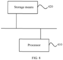
- FIG. 8 is a schematic diagram of a hardware structure of a signal receiving device provided by an embodiment.
- a signal receiving device provided in this embodiment includes a processor 410 and a storage means 420.
- the processor(s) 410 and the storage means 420 in the device may be connected by a bus or in other ways, and the bus connection is taken as an example in FIG. 8 .
- One or more programs are executed by the one or more processors 410, thus causing the one or more processors to carry out the method for determining the time of arrival described in any one of the above embodiments.
- the storage means 420 of the signal receiving device may be used to store one or more programs, which may be software programs, computer-executable programs and modules, such as program instructions/modules (e.g., modules in the apparatus for determining the time of arrival shown in FIG. 7 , including a correction information generation module 310, a front edge slope calculation module 320 and a time of arrival determination module 330) corresponding to the method for determining the time of arrival in the embodiments of the present disclosure.
- the processor 410 runs the software programs, instructions, and modules stored in the storage means 420, thus implementing various functional applications and data processing of the signal receiving device, i.e., implementing the method for determining the time of arrival in the above method embodiments.
- the storage means 420 mainly includes a program storage region and a data storage region.
- the program storage region may store an operating system, an application program required for at least one function.
- the data storage region may store data created with the use of the device, etc. (such as time of arrival correction information, front edge slope, etc. in the above embodiments).
- the storage means 420 may include a high-speed random access memory, and may also include a non-volatile memory, such as at least one magnetic disk memory device, flash memory device, or other non-volatile solid state memory device.
- the storage means 420 may include a memory provided remotely from the processor 410. Such remote memories may be connected to the signal receiving device over a network. Instances of the above-mentioned networks include, but are not limited to, the Internet, an intranet, a local area network, a mobile communication network, and combinations thereof.
- the following operations are performed: generating time of arrival correction information according to front edge information of theoretical autocorrelation waveforms of positioning signals having different fading values; calculating a front edge slope corresponding to a front edge reference point of a correlation waveform of an actually received signal; and determining target correction information from the time of arrival correction information according to the front edge slope, and determining the time of arrival of the actually received signal based on the target correction information.
- the signal receiving device proposed in this embodiment and the method for determining time of arrival proposed in the above-mentioned embodiments belong to the same application concept.
- Technical details not described in detail in this embodiment can be found in any of the above-mentioned embodiments, and this embodiment has the same beneficial effect as performing the method for determining time of arrival.
- An embodiment of the present disclosure further provides a storage medium containing computer-executable instructions, which, when executed by a computer processor, cause to carry out a method for determining time of arrival, the method including: generating time of arrival correction information according to front edge information of theoretical autocorrelation waveforms of positioning signals having different fading values; calculating a front edge slope corresponding to a front edge reference point of a correlation waveform of an actually received signal; and determining target correction information from the time of arrival correction information according to the front edge slope, and determining the time of arrival of the actually received signal based on the target correction information.
- the present disclosure may be implemented by software and general-purpose hardware, and may also be implemented by hardware. Based on such understanding, the technical scheme of the present disclosure may be embodied in the form of a software product.
- the computer software product may be stored in a computer-readable storage medium, such as a floppy disk, a read-only memory (ROM), a random access memory (RAM), a flash memory (FLASH), a hard disk or an optical disk of a computer, etc., including several instructions to make the computer device (which may be a personal computer, a server, a network device, or the like) to carry out the methods described in any of the embodiments of the present disclosure.
- the block diagrams of any logic flow in the drawings of the present disclosure may represent procedure steps, or may represent interconnected logic circuits, modules and functions, or may represent a combination of procedure steps and logic circuits, modules and functions.
- Computer programs may be stored in a memory.
- the memory may be of any type suitable for a local technical environment and may be implemented using any suitable data storage technology, such as but not limited to, a read only memory (ROM), a random access memory (RAM), an optical memory apparatus and system (digital video disc (DVD) or compact disk (CD)), etc.
- the computer-readable medium may include a non-transitory storage medium.
- the data processor may be of any type suitable for a local technical environment, such as but not limited to a general-purpose computer, a special-purpose computer, a microprocessor, a digital signal processor (DSP), an application specific integrated circuit (ASIC), a field-programmable gate array (FPGA) and a processor based on a multi-core processor architecture.
- a general-purpose computer such as but not limited to a general-purpose computer, a special-purpose computer, a microprocessor, a digital signal processor (DSP), an application specific integrated circuit (ASIC), a field-programmable gate array (FPGA) and a processor based on a multi-core processor architecture.
- DSP digital signal processor
- ASIC application specific integrated circuit
- FPGA field-programmable gate array
Landscapes
- Engineering & Computer Science (AREA)
- Physics & Mathematics (AREA)
- General Physics & Mathematics (AREA)
- Radar, Positioning & Navigation (AREA)
- Remote Sensing (AREA)
- Computer Networks & Wireless Communication (AREA)
- Signal Processing (AREA)
- Position Fixing By Use Of Radio Waves (AREA)
Applications Claiming Priority (2)
| Application Number | Priority Date | Filing Date | Title |
|---|---|---|---|
| CN202010251397.7A CN111901743B (zh) | 2020-04-01 | 2020-04-01 | 到达时间的确定方法、装置、信号接收设备及存储介质 |
| PCT/CN2020/138462 WO2021196764A1 (zh) | 2020-04-01 | 2020-12-23 | 到达时间的确定方法、装置、信号接收设备及存储介质 |
Publications (2)
| Publication Number | Publication Date |
|---|---|
| EP4132015A1 true EP4132015A1 (de) | 2023-02-08 |
| EP4132015A4 EP4132015A4 (de) | 2024-05-08 |
Family
ID=73206213
Family Applications (1)
| Application Number | Title | Priority Date | Filing Date |
|---|---|---|---|
| EP20928105.4A Pending EP4132015A4 (de) | 2020-04-01 | 2020-12-23 | Verfahren und vorrichtung zum bestimmen der ankunftszeit, signalempfangsvorrichtung und speichermedium |
Country Status (4)
| Country | Link |
|---|---|
| US (1) | US12253619B2 (de) |
| EP (1) | EP4132015A4 (de) |
| CN (1) | CN111901743B (de) |
| WO (1) | WO2021196764A1 (de) |
Families Citing this family (3)
| Publication number | Priority date | Publication date | Assignee | Title |
|---|---|---|---|---|
| CN111901743B (zh) * | 2020-04-01 | 2025-07-29 | 中兴通讯股份有限公司 | 到达时间的确定方法、装置、信号接收设备及存储介质 |
| CN112379335B (zh) * | 2020-11-13 | 2024-07-26 | 清源智翔(重庆)科技有限公司 | 一种基于幅度差分信息的到达时间测量方法 |
| CN113777987B (zh) * | 2021-09-13 | 2024-08-30 | 天津津航计算技术研究所 | 一种支持波形修正的自适应离散信号采集装置 |
Family Cites Families (15)
| Publication number | Priority date | Publication date | Assignee | Title |
|---|---|---|---|---|
| US5266953A (en) * | 1991-08-01 | 1993-11-30 | Allied-Signal Inc. | Adaptive fixed-threshold pulse time-of-arrival detection apparatus for precision distance measuring equipment applications |
| GB0327794D0 (en) * | 2003-11-29 | 2003-12-31 | Koninkl Philips Electronics Nv | Positioning method and apparatus |
| US7574221B2 (en) | 2006-08-03 | 2009-08-11 | Ntt Docomo, Inc. | Method for estimating jointly time-of-arrival of signals and terminal location |
| DE602008004859D1 (de) * | 2007-07-30 | 2011-03-24 | Core Logic Inc | Positionsmessung |
| US7667649B2 (en) * | 2007-12-10 | 2010-02-23 | Trueposition, Inc. | Detection of time of arrival of CDMA signals in a wireless location system |
| US8249622B2 (en) | 2008-11-26 | 2012-08-21 | Andrew, Llc | System and method for multiple range estimation location |
| WO2013166546A1 (en) * | 2012-05-07 | 2013-11-14 | Commonwealth Scientific And Industrial Research Organisation | Wireless positioning |
| CN104237740A (zh) | 2014-09-23 | 2014-12-24 | 国家电网公司 | 架空线-电缆混合线路分布式故障测距方法 |
| CN104219761A (zh) * | 2014-10-09 | 2014-12-17 | 中国石油大学(华东) | 一种基于最大斜率的超宽带无线定位方法 |
| CN107015250B (zh) * | 2017-04-19 | 2019-09-06 | 北京邮电大学 | 一种基于线性回归的多径抑制方法及装置 |
| US20180329023A1 (en) | 2017-05-10 | 2018-11-15 | Fernando Perez-Cruz | System and method for wireless time-of-arrival localization |
| US10880678B1 (en) * | 2018-08-07 | 2020-12-29 | Nestwave Sas | Indoor and outdoor geolocation and time of arrival estimation |
| CN110346756B (zh) | 2019-07-10 | 2023-06-06 | 四川中电昆辰科技有限公司 | 一种信号包络检测装置及方法及其到达时间修正方法 |
| CN110346755B (zh) | 2019-07-10 | 2023-06-27 | 四川中电昆辰科技有限公司 | 一种信号幅值检测装置及方法及其到达时间修正方法 |
| CN111901743B (zh) | 2020-04-01 | 2025-07-29 | 中兴通讯股份有限公司 | 到达时间的确定方法、装置、信号接收设备及存储介质 |
-
2020
- 2020-04-01 CN CN202010251397.7A patent/CN111901743B/zh active Active
- 2020-12-23 WO PCT/CN2020/138462 patent/WO2021196764A1/zh not_active Ceased
- 2020-12-23 US US17/785,625 patent/US12253619B2/en active Active
- 2020-12-23 EP EP20928105.4A patent/EP4132015A4/de active Pending
Also Published As
| Publication number | Publication date |
|---|---|
| US12253619B2 (en) | 2025-03-18 |
| CN111901743B (zh) | 2025-07-29 |
| EP4132015A4 (de) | 2024-05-08 |
| US20230029291A1 (en) | 2023-01-26 |
| CN111901743A (zh) | 2020-11-06 |
| WO2021196764A1 (zh) | 2021-10-07 |
Similar Documents
| Publication | Publication Date | Title |
|---|---|---|
| US12253619B2 (en) | Method and apparatus for determining time of arrival, signal receiving device, and storage medium | |
| KR102416604B1 (ko) | 무선통신 시스템의 정밀 측위 방법 및 장치 | |
| US7138946B2 (en) | System and method for position detection of a terminal in a network | |
| US20210235359A1 (en) | Path discrimination | |
| CN108449298B (zh) | 一种适应于高速宽带通信的定时同步与频偏估计方法 | |
| CN107003383B (zh) | 对移动终端定位时的到达时间toa获取方法及装置 | |
| CN113747338B (zh) | 一种信息上报方法、装置、设备及可读存储介质 | |
| CN111123312A (zh) | 一种高动态低信噪比环境下的卫星弱信号捕获方法及系统 | |
| CN106912101B (zh) | 到达时间差定位法及装置 | |
| CN118555179A (zh) | 一种基于峰均比的帧同步方法、装置及电子设备 | |
| EP4133815A1 (de) | Positionsschätzung | |
| WO2024140841A1 (zh) | 感知方法及装置 | |
| KR20240160187A (ko) | 감지 방법, 수신기 및 저장 매체 | |
| WO2023131192A1 (zh) | 定位方法、装置、基站、定位服务器及可读存储介质 | |
| CA1206564A (en) | Differential ecd detector for loran c receiver | |
| CN111901274B (zh) | 一种到达时间确定方法、装置、终端设备及存储介质 | |
| CN107181708B (zh) | 频率估计方法及定位接收机 | |
| US20240073065A1 (en) | Method and system for multicarrier signal tracking based on deep learning and high precision positioning | |
| CN115480209B (zh) | 一种多天线uwb的nlos识别方法 | |
| CN111585611B (zh) | 基于cffh/ds系统的帧同步方法及装置 | |
| CN109525525A (zh) | 一种信号处理方法及装置 | |
| CN101310449B (zh) | 在脉冲传输中检测路径的方法和实现该方法的装置 | |
| CN121173369A (zh) | 一种用于卫星通信终端设备的下行同步系统及方法 | |
| CN110602015B (zh) | 一种ofdm系统中多普勒频偏补偿、信号发送方法及装置 | |
| Liang et al. | Practical Indoor Localization Based on Soft Information Cross-Correlation in Wireless Sensor Networks |
Legal Events
| Date | Code | Title | Description |
|---|---|---|---|
| STAA | Information on the status of an ep patent application or granted ep patent |
Free format text: STATUS: THE INTERNATIONAL PUBLICATION HAS BEEN MADE |
|
| PUAI | Public reference made under article 153(3) epc to a published international application that has entered the european phase |
Free format text: ORIGINAL CODE: 0009012 |
|
| STAA | Information on the status of an ep patent application or granted ep patent |
Free format text: STATUS: REQUEST FOR EXAMINATION WAS MADE |
|
| 17P | Request for examination filed |
Effective date: 20220627 |
|
| AK | Designated contracting states |
Kind code of ref document: A1 Designated state(s): AL AT BE BG CH CY CZ DE DK EE ES FI FR GB GR HR HU IE IS IT LI LT LU LV MC MK MT NL NO PL PT RO RS SE SI SK SM TR |
|
| DAV | Request for validation of the european patent (deleted) | ||
| DAX | Request for extension of the european patent (deleted) | ||
| A4 | Supplementary search report drawn up and despatched |
Effective date: 20240409 |
|
| RIC1 | Information provided on ipc code assigned before grant |
Ipc: G01S 5/02 20100101ALI20240403BHEP Ipc: G01S 5/06 20060101ALI20240403BHEP Ipc: H04W 64/00 20090101ALI20240403BHEP Ipc: H04W 4/02 20180101AFI20240403BHEP |
|
| STAA | Information on the status of an ep patent application or granted ep patent |
Free format text: STATUS: EXAMINATION IS IN PROGRESS |
|
| 17Q | First examination report despatched |
Effective date: 20250806 |