EP4131997A1 - Kopfhörer - Google Patents
Kopfhörer Download PDFInfo
- Publication number
- EP4131997A1 EP4131997A1 EP21938133.2A EP21938133A EP4131997A1 EP 4131997 A1 EP4131997 A1 EP 4131997A1 EP 21938133 A EP21938133 A EP 21938133A EP 4131997 A1 EP4131997 A1 EP 4131997A1
- Authority
- EP
- European Patent Office
- Prior art keywords
- earphone
- user
- noise
- microphone
- ear
- Prior art date
- Legal status (The legal status is an assumption and is not a legal conclusion. Google has not performed a legal analysis and makes no representation as to the accuracy of the status listed.)
- Pending
Links
Images


Classifications
-
- G—PHYSICS
- G10—MUSICAL INSTRUMENTS; ACOUSTICS
- G10K—SOUND-PRODUCING DEVICES; METHODS OR DEVICES FOR PROTECTING AGAINST, OR FOR DAMPING, NOISE OR OTHER ACOUSTIC WAVES IN GENERAL; ACOUSTICS NOT OTHERWISE PROVIDED FOR
- G10K11/00—Methods or devices for transmitting, conducting or directing sound in general; Methods or devices for protecting against, or for damping, noise or other acoustic waves in general
- G10K11/16—Methods or devices for protecting against, or for damping, noise or other acoustic waves in general
- G10K11/175—Methods or devices for protecting against, or for damping, noise or other acoustic waves in general using interference effects; Masking sound
- G10K11/178—Methods or devices for protecting against, or for damping, noise or other acoustic waves in general using interference effects; Masking sound by electro-acoustically regenerating the original acoustic waves in anti-phase
- G10K11/1781—Methods or devices for protecting against, or for damping, noise or other acoustic waves in general using interference effects; Masking sound by electro-acoustically regenerating the original acoustic waves in anti-phase characterised by the analysis of input or output signals, e.g. frequency range, modes, transfer functions
- G10K11/17821—Methods or devices for protecting against, or for damping, noise or other acoustic waves in general using interference effects; Masking sound by electro-acoustically regenerating the original acoustic waves in anti-phase characterised by the analysis of input or output signals, e.g. frequency range, modes, transfer functions characterised by the analysis of the input signals only
- G10K11/17823—Reference signals, e.g. ambient acoustic environment
-
- H—ELECTRICITY
- H04—ELECTRIC COMMUNICATION TECHNIQUE
- H04R—LOUDSPEAKERS, MICROPHONES, GRAMOPHONE PICK-UPS OR LIKE ACOUSTIC ELECTROMECHANICAL TRANSDUCERS; ELECTRIC HEARING AIDS; PUBLIC ADDRESS SYSTEMS
- H04R1/00—Details of transducers, loudspeakers or microphones
- H04R1/10—Earpieces; Attachments therefor ; Earphones; Monophonic headphones
- H04R1/105—Earpiece supports, e.g. ear hooks
-
- G—PHYSICS
- G10—MUSICAL INSTRUMENTS; ACOUSTICS
- G10K—SOUND-PRODUCING DEVICES; METHODS OR DEVICES FOR PROTECTING AGAINST, OR FOR DAMPING, NOISE OR OTHER ACOUSTIC WAVES IN GENERAL; ACOUSTICS NOT OTHERWISE PROVIDED FOR
- G10K11/00—Methods or devices for transmitting, conducting or directing sound in general; Methods or devices for protecting against, or for damping, noise or other acoustic waves in general
- G10K11/16—Methods or devices for protecting against, or for damping, noise or other acoustic waves in general
- G10K11/175—Methods or devices for protecting against, or for damping, noise or other acoustic waves in general using interference effects; Masking sound
- G10K11/178—Methods or devices for protecting against, or for damping, noise or other acoustic waves in general using interference effects; Masking sound by electro-acoustically regenerating the original acoustic waves in anti-phase
- G10K11/1785—Methods, e.g. algorithms; Devices
- G10K11/17857—Geometric disposition, e.g. placement of microphones
-
- G—PHYSICS
- G10—MUSICAL INSTRUMENTS; ACOUSTICS
- G10K—SOUND-PRODUCING DEVICES; METHODS OR DEVICES FOR PROTECTING AGAINST, OR FOR DAMPING, NOISE OR OTHER ACOUSTIC WAVES IN GENERAL; ACOUSTICS NOT OTHERWISE PROVIDED FOR
- G10K11/00—Methods or devices for transmitting, conducting or directing sound in general; Methods or devices for protecting against, or for damping, noise or other acoustic waves in general
- G10K11/16—Methods or devices for protecting against, or for damping, noise or other acoustic waves in general
- G10K11/175—Methods or devices for protecting against, or for damping, noise or other acoustic waves in general using interference effects; Masking sound
- G10K11/178—Methods or devices for protecting against, or for damping, noise or other acoustic waves in general using interference effects; Masking sound by electro-acoustically regenerating the original acoustic waves in anti-phase
- G10K11/1787—General system configurations
- G10K11/17873—General system configurations using a reference signal without an error signal, e.g. pure feedforward
-
- H—ELECTRICITY
- H04—ELECTRIC COMMUNICATION TECHNIQUE
- H04R—LOUDSPEAKERS, MICROPHONES, GRAMOPHONE PICK-UPS OR LIKE ACOUSTIC ELECTROMECHANICAL TRANSDUCERS; ELECTRIC HEARING AIDS; PUBLIC ADDRESS SYSTEMS
- H04R1/00—Details of transducers, loudspeakers or microphones
- H04R1/10—Earpieces; Attachments therefor ; Earphones; Monophonic headphones
- H04R1/1008—Earpieces of the supra-aural or circum-aural type
-
- H—ELECTRICITY
- H04—ELECTRIC COMMUNICATION TECHNIQUE
- H04R—LOUDSPEAKERS, MICROPHONES, GRAMOPHONE PICK-UPS OR LIKE ACOUSTIC ELECTROMECHANICAL TRANSDUCERS; ELECTRIC HEARING AIDS; PUBLIC ADDRESS SYSTEMS
- H04R1/00—Details of transducers, loudspeakers or microphones
- H04R1/10—Earpieces; Attachments therefor ; Earphones; Monophonic headphones
- H04R1/1058—Manufacture or assembly
- H04R1/1066—Constructional aspects of the interconnection between earpiece and earpiece support
-
- H—ELECTRICITY
- H04—ELECTRIC COMMUNICATION TECHNIQUE
- H04R—LOUDSPEAKERS, MICROPHONES, GRAMOPHONE PICK-UPS OR LIKE ACOUSTIC ELECTROMECHANICAL TRANSDUCERS; ELECTRIC HEARING AIDS; PUBLIC ADDRESS SYSTEMS
- H04R1/00—Details of transducers, loudspeakers or microphones
- H04R1/10—Earpieces; Attachments therefor ; Earphones; Monophonic headphones
- H04R1/1083—Reduction of ambient noise
-
- H—ELECTRICITY
- H04—ELECTRIC COMMUNICATION TECHNIQUE
- H04R—LOUDSPEAKERS, MICROPHONES, GRAMOPHONE PICK-UPS OR LIKE ACOUSTIC ELECTROMECHANICAL TRANSDUCERS; ELECTRIC HEARING AIDS; PUBLIC ADDRESS SYSTEMS
- H04R1/00—Details of transducers, loudspeakers or microphones
- H04R1/10—Earpieces; Attachments therefor ; Earphones; Monophonic headphones
- H04R1/1091—Details not provided for in groups H04R1/1008 - H04R1/1083
-
- H—ELECTRICITY
- H04—ELECTRIC COMMUNICATION TECHNIQUE
- H04R—LOUDSPEAKERS, MICROPHONES, GRAMOPHONE PICK-UPS OR LIKE ACOUSTIC ELECTROMECHANICAL TRANSDUCERS; ELECTRIC HEARING AIDS; PUBLIC ADDRESS SYSTEMS
- H04R1/00—Details of transducers, loudspeakers or microphones
- H04R1/20—Arrangements for obtaining desired frequency or directional characteristics
- H04R1/32—Arrangements for obtaining desired frequency or directional characteristics for obtaining desired directional characteristic only
- H04R1/40—Arrangements for obtaining desired frequency or directional characteristics for obtaining desired directional characteristic only by combining a number of identical transducers
- H04R1/406—Arrangements for obtaining desired frequency or directional characteristics for obtaining desired directional characteristic only by combining a number of identical transducers microphones
-
- H—ELECTRICITY
- H04—ELECTRIC COMMUNICATION TECHNIQUE
- H04R—LOUDSPEAKERS, MICROPHONES, GRAMOPHONE PICK-UPS OR LIKE ACOUSTIC ELECTROMECHANICAL TRANSDUCERS; ELECTRIC HEARING AIDS; PUBLIC ADDRESS SYSTEMS
- H04R3/00—Circuits for transducers
- H04R3/005—Circuits for transducers for combining the signals of two or more microphones
-
- H—ELECTRICITY
- H04—ELECTRIC COMMUNICATION TECHNIQUE
- H04R—LOUDSPEAKERS, MICROPHONES, GRAMOPHONE PICK-UPS OR LIKE ACOUSTIC ELECTROMECHANICAL TRANSDUCERS; ELECTRIC HEARING AIDS; PUBLIC ADDRESS SYSTEMS
- H04R3/00—Circuits for transducers
- H04R3/02—Circuits for transducers for preventing acoustic reaction, i.e. acoustic oscillatory feedback
-
- H—ELECTRICITY
- H04—ELECTRIC COMMUNICATION TECHNIQUE
- H04R—LOUDSPEAKERS, MICROPHONES, GRAMOPHONE PICK-UPS OR LIKE ACOUSTIC ELECTROMECHANICAL TRANSDUCERS; ELECTRIC HEARING AIDS; PUBLIC ADDRESS SYSTEMS
- H04R3/00—Circuits for transducers
- H04R3/04—Circuits for transducers for correcting frequency response
-
- H—ELECTRICITY
- H04—ELECTRIC COMMUNICATION TECHNIQUE
- H04R—LOUDSPEAKERS, MICROPHONES, GRAMOPHONE PICK-UPS OR LIKE ACOUSTIC ELECTROMECHANICAL TRANSDUCERS; ELECTRIC HEARING AIDS; PUBLIC ADDRESS SYSTEMS
- H04R9/00—Transducers of moving-coil, moving-strip, or moving-wire type
- H04R9/06—Loudspeakers
-
- G—PHYSICS
- G10—MUSICAL INSTRUMENTS; ACOUSTICS
- G10K—SOUND-PRODUCING DEVICES; METHODS OR DEVICES FOR PROTECTING AGAINST, OR FOR DAMPING, NOISE OR OTHER ACOUSTIC WAVES IN GENERAL; ACOUSTICS NOT OTHERWISE PROVIDED FOR
- G10K2210/00—Details of active noise control [ANC] covered by G10K11/178 but not provided for in any of its subgroups
- G10K2210/10—Applications
- G10K2210/108—Communication systems, e.g. where useful sound is kept and noise is cancelled
- G10K2210/1081—Earphones, e.g. for telephones, ear protectors or headsets
-
- G—PHYSICS
- G10—MUSICAL INSTRUMENTS; ACOUSTICS
- G10K—SOUND-PRODUCING DEVICES; METHODS OR DEVICES FOR PROTECTING AGAINST, OR FOR DAMPING, NOISE OR OTHER ACOUSTIC WAVES IN GENERAL; ACOUSTICS NOT OTHERWISE PROVIDED FOR
- G10K2210/00—Details of active noise control [ANC] covered by G10K11/178 but not provided for in any of its subgroups
- G10K2210/30—Means
- G10K2210/301—Computational
- G10K2210/3023—Estimation of noise, e.g. on error signals
- G10K2210/30231—Sources, e.g. identifying noisy processes or components
-
- G—PHYSICS
- G10—MUSICAL INSTRUMENTS; ACOUSTICS
- G10K—SOUND-PRODUCING DEVICES; METHODS OR DEVICES FOR PROTECTING AGAINST, OR FOR DAMPING, NOISE OR OTHER ACOUSTIC WAVES IN GENERAL; ACOUSTICS NOT OTHERWISE PROVIDED FOR
- G10K2210/00—Details of active noise control [ANC] covered by G10K11/178 but not provided for in any of its subgroups
- G10K2210/30—Means
- G10K2210/301—Computational
- G10K2210/3025—Determination of spectrum characteristics, e.g. FFT
-
- G—PHYSICS
- G10—MUSICAL INSTRUMENTS; ACOUSTICS
- G10K—SOUND-PRODUCING DEVICES; METHODS OR DEVICES FOR PROTECTING AGAINST, OR FOR DAMPING, NOISE OR OTHER ACOUSTIC WAVES IN GENERAL; ACOUSTICS NOT OTHERWISE PROVIDED FOR
- G10K2210/00—Details of active noise control [ANC] covered by G10K11/178 but not provided for in any of its subgroups
- G10K2210/30—Means
- G10K2210/301—Computational
- G10K2210/3035—Models, e.g. of the acoustic system
- G10K2210/30351—Identification of the environment for applying appropriate model characteristics
-
- G—PHYSICS
- G10—MUSICAL INSTRUMENTS; ACOUSTICS
- G10K—SOUND-PRODUCING DEVICES; METHODS OR DEVICES FOR PROTECTING AGAINST, OR FOR DAMPING, NOISE OR OTHER ACOUSTIC WAVES IN GENERAL; ACOUSTICS NOT OTHERWISE PROVIDED FOR
- G10K2210/00—Details of active noise control [ANC] covered by G10K11/178 but not provided for in any of its subgroups
- G10K2210/30—Means
- G10K2210/301—Computational
- G10K2210/3038—Neural networks
-
- G—PHYSICS
- G10—MUSICAL INSTRUMENTS; ACOUSTICS
- G10K—SOUND-PRODUCING DEVICES; METHODS OR DEVICES FOR PROTECTING AGAINST, OR FOR DAMPING, NOISE OR OTHER ACOUSTIC WAVES IN GENERAL; ACOUSTICS NOT OTHERWISE PROVIDED FOR
- G10K2210/00—Details of active noise control [ANC] covered by G10K11/178 but not provided for in any of its subgroups
- G10K2210/30—Means
- G10K2210/301—Computational
- G10K2210/3047—Prediction, e.g. of future values of noise
-
- G—PHYSICS
- G10—MUSICAL INSTRUMENTS; ACOUSTICS
- G10K—SOUND-PRODUCING DEVICES; METHODS OR DEVICES FOR PROTECTING AGAINST, OR FOR DAMPING, NOISE OR OTHER ACOUSTIC WAVES IN GENERAL; ACOUSTICS NOT OTHERWISE PROVIDED FOR
- G10K2210/00—Details of active noise control [ANC] covered by G10K11/178 but not provided for in any of its subgroups
- G10K2210/30—Means
- G10K2210/301—Computational
- G10K2210/3056—Variable gain
-
- H—ELECTRICITY
- H04—ELECTRIC COMMUNICATION TECHNIQUE
- H04R—LOUDSPEAKERS, MICROPHONES, GRAMOPHONE PICK-UPS OR LIKE ACOUSTIC ELECTROMECHANICAL TRANSDUCERS; ELECTRIC HEARING AIDS; PUBLIC ADDRESS SYSTEMS
- H04R1/00—Details of transducers, loudspeakers or microphones
- H04R1/10—Earpieces; Attachments therefor ; Earphones; Monophonic headphones
- H04R1/1041—Mechanical or electronic switches, or control elements
-
- H—ELECTRICITY
- H04—ELECTRIC COMMUNICATION TECHNIQUE
- H04R—LOUDSPEAKERS, MICROPHONES, GRAMOPHONE PICK-UPS OR LIKE ACOUSTIC ELECTROMECHANICAL TRANSDUCERS; ELECTRIC HEARING AIDS; PUBLIC ADDRESS SYSTEMS
- H04R1/00—Details of transducers, loudspeakers or microphones
- H04R1/10—Earpieces; Attachments therefor ; Earphones; Monophonic headphones
- H04R1/1058—Manufacture or assembly
- H04R1/1075—Mountings of transducers in earphones or headphones
-
- H—ELECTRICITY
- H04—ELECTRIC COMMUNICATION TECHNIQUE
- H04R—LOUDSPEAKERS, MICROPHONES, GRAMOPHONE PICK-UPS OR LIKE ACOUSTIC ELECTROMECHANICAL TRANSDUCERS; ELECTRIC HEARING AIDS; PUBLIC ADDRESS SYSTEMS
- H04R2420/00—Details of connection covered by H04R, not provided for in its groups
- H04R2420/07—Applications of wireless loudspeakers or wireless microphones
-
- H—ELECTRICITY
- H04—ELECTRIC COMMUNICATION TECHNIQUE
- H04R—LOUDSPEAKERS, MICROPHONES, GRAMOPHONE PICK-UPS OR LIKE ACOUSTIC ELECTROMECHANICAL TRANSDUCERS; ELECTRIC HEARING AIDS; PUBLIC ADDRESS SYSTEMS
- H04R2460/00—Details of hearing devices, i.e. of ear- or headphones covered by H04R1/10 or H04R5/033 but not provided for in any of their subgroups, or of hearing aids covered by H04R25/00 but not provided for in any of its subgroups
- H04R2460/01—Hearing devices using active noise cancellation
-
- H—ELECTRICITY
- H04—ELECTRIC COMMUNICATION TECHNIQUE
- H04R—LOUDSPEAKERS, MICROPHONES, GRAMOPHONE PICK-UPS OR LIKE ACOUSTIC ELECTROMECHANICAL TRANSDUCERS; ELECTRIC HEARING AIDS; PUBLIC ADDRESS SYSTEMS
- H04R2460/00—Details of hearing devices, i.e. of ear- or headphones covered by H04R1/10 or H04R5/033 but not provided for in any of their subgroups, or of hearing aids covered by H04R25/00 but not provided for in any of its subgroups
- H04R2460/09—Non-occlusive ear tips, i.e. leaving the ear canal open, for both custom and non-custom tips
-
- H—ELECTRICITY
- H04—ELECTRIC COMMUNICATION TECHNIQUE
- H04R—LOUDSPEAKERS, MICROPHONES, GRAMOPHONE PICK-UPS OR LIKE ACOUSTIC ELECTROMECHANICAL TRANSDUCERS; ELECTRIC HEARING AIDS; PUBLIC ADDRESS SYSTEMS
- H04R2460/00—Details of hearing devices, i.e. of ear- or headphones covered by H04R1/10 or H04R5/033 but not provided for in any of their subgroups, or of hearing aids covered by H04R25/00 but not provided for in any of its subgroups
- H04R2460/11—Aspects relating to vents, e.g. shape, orientation, acoustic properties in ear tips of hearing devices to prevent occlusion
-
- H—ELECTRICITY
- H04—ELECTRIC COMMUNICATION TECHNIQUE
- H04R—LOUDSPEAKERS, MICROPHONES, GRAMOPHONE PICK-UPS OR LIKE ACOUSTIC ELECTROMECHANICAL TRANSDUCERS; ELECTRIC HEARING AIDS; PUBLIC ADDRESS SYSTEMS
- H04R2460/00—Details of hearing devices, i.e. of ear- or headphones covered by H04R1/10 or H04R5/033 but not provided for in any of their subgroups, or of hearing aids covered by H04R25/00 but not provided for in any of its subgroups
- H04R2460/13—Hearing devices using bone conduction transducers
Definitions
- the present disclosure relates the acoustic field, and in particular, to earphones.
- Active noise reduction technology is a technology that uses a speaker of an earphone to output sound waves opposite to external environmental noise to cancel the environmental noise.
- Earphones may usually be divided into two types including in-ear earphones and open earphones.
- An in-ear earphone may block a user's ear during use, and the user is likely to have feelings of blockage, foreign matters, swelling, pain, etc., when wearing the in-ear earphone for a long time.
- An open earphone may not block the user's ears, which is good for long-term wearing.
- the external noise is relatively large, the noise reduction performance of the open earphone may be not obvious, which may reduce the user's listening experience.
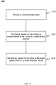
- the earphone may include: a fixing structure configured to fix the earphone near a user's ear without blocking the user's ear canal and including a hook-shaped component and a body part, wherein when the user wears the earphone, the hook-shaped component is hung between a first side of the ear and a head of the user, and the body part contacts a second side of the ear; a first microphone array located in the body part and configured to pick up environmental noise; a processor located in the hook-shaped component or the body part and configured to: estimate a sound field at a target spatial position using the first microphone array, the target spatial position being closer to the user's ear canal than any microphone in the first microphone array, and generate, based on the estimated sound field at the target spatial position, a noise reduction signal; and a speaker located in the body part and configured to output a target signal according to the noise reduction signal, the target signal being transmitted to outside of the earphone through a sound outlet hole for
- the body part may include a connecting component and a holding component.
- the holding component may contact the second side of the ear, and the connecting component may connect the hook-shaped component and the holding component.
- the connecting component when the user wears the earphone, the connecting component may extend from the first side of the ear to the second side of the ear, the connecting component may cooperate with the hook-shaped component to provide the holding component with a pressing force on the second side of the ear, and the connecting component may cooperate with the holding component to provide the hook-shaped component with a pressing force on the first side of the ear.
- the hook-shaped component in a direction from a first connection point between the hook-shaped component and the connecting component to a free end of the hook-shaped component, may be bent towards the first side of the ear to form a first contact point with the first side of the ear, and the holding component may form a second contact point with the second side of the ear.
- a distance between the first contact point and the second contact point along an extension direction of the connecting component in a natural state may be smaller than a distance between the first contact point and the second contact point along the extension direction of the connecting component in a wearing state to provide the holding component with a pressing force on the second side of the ear and provide the hook-shaped component with the pressing force on the first side of the ear.
- the hook-shaped component in a direction from a first connection point between the hook-shaped component and the connecting component to a free end of the hook-shaped component, may be bent towards the head to form a first contact point and a third contact point with the head.
- the first contact point is located between the third contact point and the first connection point, so that the hook-shaped component forms a lever structure with the first contact point as a fulcrum.
- a force directed towards outside of the head and provided by the head at the third contact point may be converted by the lever structure into a force directed to the head at the first connection point, and the force directed to the head at the first connection point may provide the holding component with the pressing force on the second side of the ear via the connecting component.
- the speaker may be disposed in the holding component, and the holding component may have a multi-segment structure to adjust a relative position of the speaker on an overall structure of the earphone.
- the holding component may include a first holding segment, a second holding segment, and a third holding segment that are connected end to end in sequence.
- One end of the first holding segment facing away from the second holding segment may be connected to the connecting component.
- the second holding segment may be folded back relative to the first holding segment and may maintain a distance away from the first holding segment to make the first holding segment and the second holding segment be in a U-shaped structure.
- the speaker may be arranged in the third holding segment.
- the holding component may include a first holding segment, a second holding segment, and a third holding segment that are connected end to end in sequence.
- One end of the first holding segment facing away from the second holding segment may be connected to the connecting component.
- the second holding segment may be bent relative to the first holding segment.
- the third holding segment and the first holding segment may be disposed side by side with each other at a distance.
- the speaker may be disposed in the third holding segment.
- the sound outlet hole may be provided on a side of the holding component facing the ear to make the target signal output by the speaker be transmitted to the ear through the sound outlet hole.
- the side of the holding component facing the ear may include a first region and a second region.
- the first region may be provided with the sound outlet hole.
- the second region may be farther away from the connecting component than the first region and may protrude more toward the ear than the first region, so as to allow the sound outlet hole to be spaced from the ear in a wearing state.
- a distance between the sound outlet hole and the user's ear canal may be less than 10 mm.
- a pressure relief hole may be provided on a side of the holding component along a vertical axis direction and close to a top of the user's head.
- the pressure relief hole may be farther away from the user's ear canal than the sound outlet hole.
- a distance between the pressure relief hole and the user's ear canal may be in a range of 5 mm to 15 mm.
- an included angle between a connection line between the pressure relief hole and the sound outlet hole and a thickness direction of the holding component may be in a range of 0° to 50°.
- the pressure relief hole and the sound outlet hole may form an acoustic dipole.
- the first microphone array may be disposed in a first target region.
- the first target region may be an acoustic zero point position of a radiated sound field of the acoustic dipole.
- the first microphone array may be located in the connecting component.
- a first included angle may be formed between a connection line between the first microphone array and the sound outlet hole and a connection line between the sound outlet hole and the pressure relief hole.
- a second included angle may be formed between a connection line between the first microphone array and the pressure relief hole and the connection line between the sound outlet hole and the pressure relief hole.
- a difference between the first included angle and the second included angle may be less than or equal to 30°.
- a distance between the first microphone array and the sound outlet hole may be a first distance.
- a distance between the first microphone array and the pressure relief hole may be a second distance.
- a difference between the first distance and the second distance may be less than or equal to 6 mm.
- the generating, based on the estimated sound field at the target spatial position, a noise reduction signal may include: estimating, based on the picked-up environmental noise, noise at the target spatial position; and generating, based on the noise at the target spatial position and the estimated sound field at the target spatial position, the noise reduction signal.
- the earphone may further include one or more sensors located in the hook-shaped component and/or the body part and configured to obtain motion information of the earphone.
- the processor may be further configured to: update, based on the motion information, the noise at the target spatial position and the estimated sound field at the target spatial position; and generate, based on the updated noise at the target spatial position and the updated estimated sound field at the target spatial position, the noise reduction signal.
- the estimating, based on the picked-up environmental noise, noise at the target spatial position may include: determining one or more spatial noise sources associated with the picked-up environmental noise; and estimating, based on the one or more spatial noise sources, the noise at the target spatial position.
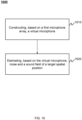
- the estimating a sound field at a target spatial position using the first microphone array may include: constructing, based on the first microphone array, a virtual microphone, wherein the virtual microphone includes a mathematical model or a machine learning model and is configured to represent audio data collected by the microphone if the target spatial position includes the microphone; and estimating, based on the virtual microphone, the sound field of the target spatial position.
- the generating, based on the estimated sound field at the target spatial position, a noise reduction signal may include: estimating, based on the virtual microphone, noise at the target spatial position; and generating, based on the noise at the target spatial position and the estimated sound field at the target spatial position, the noise reduction signal.
- the earphone may include a second microphone located in the body part and configured to pick up the environmental noise and the target signal.
- the processor may be configured to: update, based on a sound signal picked up by the second microphone, the noise reduction signal.
- the second microphone may include at least one microphone closer to the user's ear canal than any microphone in the first microphone array.
- the second microphone may be disposed in a second target region, and the second target area may be a region on the holding component close to the user's ear canal.
- a distance between the second microphone and the user's ear canal may be less than 10 mm.
- a distance between the second microphone and the sound outlet hole along a sagittal axis direction may be less than 10 mm.
- a distance between the second microphone and the sound outlet hole along a vertical axis direction may be in a range of 2 mm to 5 mm.
- the updating, based on a sound signal picked up by the second microphone, the sound reduction signal may include: estimating, based on the sound signal picked up by the second microphone, a sound field at the user's ear canal; and updating, according to the sound field at the user's ear canal, the noise reduction signal.
- the generating, based on the estimated sound field at the target spatial position, a noise reduction signal may include: dividing the picked-up environmental noise into a plurality of frequency bands, the plurality of frequency bands corresponding to different frequency ranges; and generating, based on at least one of the plurality of frequency bands, the noise reduction signal corresponding to each of the at least one frequency band.
- the generating, based on at least one of the plurality of frequency bands, the noise reduction signal corresponding to each of the at least one frequency band may include: obtaining sound pressure levels of the plurality of frequency bands; and generating, based on the sound pressure levels of the plurality of frequency bands and the frequency ranges of the plurality of frequency bands, the noise reduction signal corresponding to each of the at least one frequency band, wherein the at least one frequency band is part of the plurality of frequency bands.
- the first microphone array may include a bone conduction microphone configured to pick up a voice of the user
- the estimating, based on the picked-up environmental noise, noise at the target spatial position may include: removing components associated with a signal picked up by the bone conduction microphone from the picked up environmental noise to update the environmental noise; and estimating, based on the updated environmental noise, the noise at the target spatial position.
- the earphone may further include an adjustment module configured to obtain an input of a user.
- the processor may be further configured to adjust the noise reduction signal according to the input of the user.
- the earphone may be an open earphone.
- the open earphone may fix a speaker near a user's ear through a fixing structure without blocking the user's ear canal.
- the earphone may include the fixing structure, a first microphone array, a processor, and a speaker.
- the fixing structure may be configured to fix the earphone near a user's ear without blocking the user's ear canal.
- the first microphone array, the processor, and the speaker may be located in the fixing structure to implement an active noise reduction function of the earphone.
- the fixing structure may include a hook-shaped component and a body part.
- the hook-shaped component When the user wears the earphone, the hook-shaped component may be hung between a first side of the ear and the head of the user, and the body part may contact a second side of the ear.
- the body part may include a connecting component and a holding component.
- the holding component When the user wears the earphone, the holding component may contact the second side of the ear, and the connecting component may connect the hook-shaped component and the holding component.
- the connecting component may extend from the first side of the ear to the second side of the ear, and the connecting component may cooperate with the hook-shaped component to provide the holding component with a pressing force on the second side of the ear.
- the connecting component may cooperate with the holding component to provide the hook-shaped component with a pressing force on the first side of the ear, so that the earphone may clamp the user's ear, and the wearing stability of the earphone may be ensured.
- the first microphone array located in the body part of the earphone may be configured to pick up environmental noise.
- the processor located in the hook-shaped component or the body part of the earphone may be configured to estimate a sound field at a target spatial position.
- the target spatial position may include a spatial position close to the user's ear canal at a specific distance. For example, the target spatial position may be closer to the user's ear canal than any microphone in the first microphone array.
- each microphone in the first microphone array may be distributed at different positions near the user's ear canal.
- the processor may estimate a sound field at a position close to the user's ear canal (e.g., the target spatial position) according to the environmental noise collected by each microphone in the first microphone array.
- the speaker may be located in the body part (the holding component) and configured to output a target signal according to a noise reduction signal.
- the target signal may be transmitted to outside of the earphone through a sound outlet hole on the holding component for reducing the environmental noise heard by the user.
- the body part may include a second microphone.
- the second microphone may be closer to the user's ear canal than the first microphone array.
- a sound signal collected by the second microphone may be more consistent with the sound heard by the user and reflect the sound heard by the user.
- the processor may update the noise reduction signal according to the sound signal collected by the second microphone, so as to achieve a more ideal noise reduction effect.
- the earphone provided in the embodiments of the present disclosure can be fixed near the user's ear through the fixing structure without blocking the user's ear canal, which may allow the user's ears being unblocked and improve the stability and comfort of the earphone in wearing.
- the sound field close to the user's ear canal e.g., the target spatial position
- the first microphone array and/or the second microphone located in the fixing structure (such as the body part) and the processor may be estimated using the first microphone array and/or the second microphone located in the fixing structure (such as the body part) and the processor, and the environmental noise at the user's ear canal may be reduced using the target signal output by the speaker, thereby realizing the active noise reduction of the earphone, and improving the user's listening experience in a process of using the earphone.
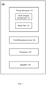
- FIG. 1 is a block diagram illustrating an exemplary earphone according to some embodiments of the present disclosure.
- the earphone 100 may include a fixing structure 110, a first microphone array 120, a processor 130, and a speaker 140.
- the first microphone array 120, the processor 130, and the speaker 140 may be located in the fixing structure 110.
- the earphone 100 may clamp the user's ear through the fixing structure 110 to fix the earphone 100 near a user's ear without blocking a user's ear canal.
- the first microphone array 120 located in the fixing structure 110 e.g., the body part
- the processor 130 may be coupled (e.g., electrically connected) to the first microphone array 120 and the speaker 140.
- the processor 130 may receive and process the electrical signal transmitted by the first microphone array 120 to generate a noise reduction signal, and transmit the generated noise reduction signal to the speaker 140.
- the speaker 140 may output a target signal according to the noise reduction signal.
- the target signal may be transmitted to outside of the earphone 100 through a sound outlet hole on the fixing structure 110 (e.g., the holding component), and may be configured to reduce or cancel the environmental noise at the user's ear canal (e.g., a target spatial position), thereby achieving active noise reduction of the earphone 100, and improving the user's listening experience in a process of using the earphone 100.
- the fixing structure 110 may include a hook-shaped component 111 and a body part 112.
- the hook-shaped component 111 may be hung between a first side of the ear and the head of the user, and the body part 112 may contact a second side of the ear.
- the first side of the ear may be a rear side of the user's ear.
- the second side of the user's ear may be a front side of the user's ear.
- the front side of the user's ear may refer to a side of the user's ear including parts such as a cymba conchae, a triangular fossa, an antihelix, a scapha, a helix, etc. (see FIG. 2 for a structure of an ear).
- the rear side of the user's ear may refer to a side of the user's ear that is away from the front side, i.e., a side opposite to the front side.
- the body part 112 may include a connecting component and a holding component.
- the holding component may contact the second side of the ear, and the connecting component may connect the hook-shaped component and the holding component.
- the connecting component may extend from the first side of the ear to the second side of the ear, and the connecting component may cooperate with the hook-shaped component to provide the holding component with a pressing force on the second side of the ear.
- the connecting component may cooperate with the holding component to provide the hook-shaped component with a pressing force on the first side of the ear, so that the earphone 100 may be clamped near the user's ear by the fixing structure 110, and the stability of the earphone 100 in wearing may be ensured.
- a part of the hook-shaped component 111 and/or the body part 112 (the connecting component and/or the holding component) that contacts the user's ear may be made of a relatively soft material, a relatively hard material, or the like, or any combination thereof.
- the relatively soft material may refer to a material whose hardness (e.g., a Shore hardness) is less than a first hardness threshold (e.g., 15A, 20A, 30A, 35A, 40A, etc.).
- a relatively soft material may have a Shore hardness of 45A-85A, 30D-60D.
- the relatively hard material may refer to a material whose hardness (e.g., a Shore hardness) is greater than a second hardness threshold (e.g., 65D, 70D, 80D, 85D, 90D, etc.).
- the relatively soft material may include, but is not limited to, polyurethanes (PU) (e.g., thermoplastic polyurethanes (TPU)), polycarbonate (PC), polyamides (PA), acrylonitrile butadiene styrene (ABS), polystyrene (PS), high impact polystyrene (HIPS), polypropylene(PP), polyethylene terephthalate (PET), polyvinyl chloride (PVC), polyurethanes (PU), polyethylene (PE), phenol formaldehyde (PF), ureaformaldehyde (UF),melamine-formaldehyde (MF),silica gel, or the like, or any combination thereof.
- PU polyurethanes
- TPU thermo
- the relatively hard material may include, but is not limited to, poly (ester sulfones) (PES), polyvinylidene chloride (PVDC), polymethyl methacrylate (PMMA), poly-ether-ether-ketone (Peek), or the like, or any combination thereof, or a mixture thereof with a reinforcing agent such as a glass fiber, a carbon fiber, etc.
- the material of the part of the hook-shaped component 111 and/or the body part 112 of the fixing structure 110 that contacts the user's ear may be chosen according to a specific condition.
- the relatively soft material may improve the comfort of the user wearing the earphone 100.
- the relatively hard material may enhance strength of the earphone 100. By reasonably configuring the materials of each component of the earphone 100, the strength of the earphone 100 may be enhanced while the comfort of the user is improved.
- the first microphone array 120 located in the body part 112 (such as the connecting component and the holding component) of the fixing structure 110 may be configured to pick up environmental noise.
- the environmental noise may refer to a combination of a plurality of external sounds in an environment where the user is located.
- the first microphone array 120 may be located near the user's ear canal. Based on the environmental noise obtained in this way, the processor 130 may more accurately calculate the noise that is actually transmitted to the user's ear canal, which may be more conducive to subsequent active noise reduction of the environmental noise heard by the user.
- the environmental noise may include the user's speech.
- the first microphone array 120 may pick up the environmental noise according to a working state of the earphone 100.
- the working state of the earphone 100 may refer to a usage state used when the user wears the earphone 100.
- the working state of the earphone 100 may include, but is not limited to, a calling state, a non-calling state (e.g., a music playing state), a state of sending a voice message, etc.
- a sound generated by the user's own speech may be regarded as the environmental noise.
- the first microphone array 120 may pick up the sound generated by the user's own speech and other environmental noises.
- the first microphone array 120 may pick up the environmental noise other than the sound generated by the user's own speech.
- the first microphone array 120 may pick up the noise emitted by a noise source located at a distance (e.g., 0.5 m, 1 m) away from the first microphone array 120.
- the first microphone array 120 may include one or more air conduction microphones.
- the air conduction microphone(s) may simultaneously obtain the external environmental noise and the sound generated by the user's speech, and designate the obtained external environmental noise and the sound generated by the user's speech as the environmental noise.
- the first microphone array 120 may also include one or more bone conduction microphones.
- a bone conduction microphone may be in direct contact with the user's skin. When the user speaks, a vibration signal generated by bones or muscles may be directly transmitted to the bone conduction microphone, and the bone conduction microphone may convert the vibration signal into an electrical signal and transmit the electrical signal to the processor 130 for processing.
- the bone conduction microphone may also not be in direct contact with the human body.
- the vibration signal generated by bones or muscles may be transmitted to the fixing structure 110 of the earphone 100 first, and then transmitted to the bone conduction microphone by the fixing structure 110.
- the processor 130 may determine the sound signal collected by the air conduction microphone as the environmental noise and perform the noise reduction on the environmental noise.
- the sound signal collected by the bone conduction microphone may be transmitted to a terminal device as a voice signal, so as to ensure speech quality of the user during the call.
- the processor 130 may control on/off states of the bone conduction microphone and the air conduction microphone based on the working state of the earphone 100.
- the on/off states of the bone conduction microphone and the air conduction microphone in the first microphone array 120 may be determined according to the working state of the earphone 100. For example, when the user wears the earphone 100 to play music, the bone conduction microphone may be in a standby state, and the air conduction microphone may be in the working state.
- the processor 130 may control the on/off state of the microphones (e.g., the bone conduction microphone, the air conduction microphone) in the first microphone array 120 by sending a control signal.
- the first microphone array 120 may include a moving-coil microphone, a ribbon microphone, a condenser microphone, an electret microphone, an electromagnetic microphone, a carbon particle microphone, or the like, or any combination thereof.
- an arrangement of the first microphone array 120 may include a linear array (e.g., a straight line, a curve), a planar array (e.g., a regular and/or irregular shape such as a cross, a circle, a ring, a polygon, a mesh, etc.), a three-dimensional array (e.g., a cylinder, a sphere, a hemisphere, a polyhedron, etc.), or the like, or any combination thereof.
- a linear array e.g., a straight line, a curve
- a planar array e.g., a regular and/or irregular shape such as a cross, a circle, a ring, a polygon, a mesh, etc.
- a three-dimensional array e.g., a cylinder, a sphere, a hemisphere, a polyhedron, etc.
- the processor 130 may be located in the hook-shaped component 111 or the body part 112 of the fixing structure 110, and the processor 130 may estimate a sound field at a target spatial position using the first microphone array 120.
- the sound field at the target spatial position may refer to distribution and changes (e.g., changes with time, changes with positions) of sound waves at or near the target spatial position.
- a physical quantity describing the sound field may include a sound pressure level, a sound frequency, a sound amplitude, a sound phase, a sound source vibration velocity, a medium (e.g., air) density, etc. Generally, these physical quantities may be functions of position and time.
- the target spatial position may refer to a spatial position close to the user's ear canal at a specific distance.
- the specific distance herein may be a fixed distance, such as 2 mm, 5 mm, 10 mm, etc.
- the target spatial position may be closer to the user's ear canal than any microphone in the first microphone array 120.
- the target spatial position may be related to a count of microphones in the first microphone array 120 and their distribution positions relative to the user's ear canal. By adjusting the count of the microphones in the first microphone array 120 and/or the distribution positions relative to the user's ear canal, the target spatial position may be adjusted. For example, the target spatial position may be made closer to the user's ear canal by increasing the count of the microphones in the first microphone array 120.
- the target spatial position may be made closer to the user's ear canal by reducing a distance between the microphones in the first microphone array 120.
- the target spatial position may be made closer to the user's ear canal by changing the arrangement of the microphones in the first microphone array 120.
- the processor 130 may be further configured to generate, based on the estimated sound field at the target spatial position, a noise reduction signal.
- the processor 130 may receive and process the environmental noise obtained by the first microphone array 120 to obtain parameters of the environmental noise (e.g., an amplitude, a phase, etc.), and estimate the sound field at the target spatial position based on the parameters of the environmental noise. Further, the processor 130 may generate, based on the estimated sound field at the target spatial position, the noise reduction signal.
- the parameters of the noise reduction signal (e.g., the amplitude, the phase, etc.) may be related to the environmental noise at the target spatial position.
- the amplitude of the noise reduction signal may be similar to an amplitude of the environmental noise at the target spatial position.
- the phase of the noise reduction signal may be approximately opposite to a phase of the environmental noise at the target spatial position.
- the processor 130 may include a hardware module and a software module.
- the hardware module may include, but is not limited to a digital signal processor (DSP), an advanced RISC machine (ARM), a central processing unit (CPU), an application specific integrated circuits (ASIC), a physics processing unit (PPU), a digital signal processor (DSP), a field programmable gate array (FPGA), a programmable logic device (PLD), a controller, a microprocessor, or the like, or any combination thereof.
- the software module may include an algorithm module.
- the speaker 140 may be located in the holding component of the fixing structure 110. When the user wears the earphone 100, the speaker 140 is located near the user's ear. The speaker 140 may output a target signal according to the noise reduction signal. The target signal may be transmitted to the user's ear through the sound outlet hole of holding component to reduce or eliminate the environmental noise transmitted to the user's ear canal.
- the speaker 140 may include an electrodynamic speaker (e.g., a moving-coil speaker), a magnetic speaker, an ion speaker, an electrostatic speaker (or a condenser speaker), a piezoelectric speaker, or the like, or any combination thereof.
- the speaker 140 may include an air conduction speaker and a bone conduction speaker.
- a count of the speakers 140 may be one or more.
- the speaker may output the target signal to eliminate the environmental noise, and simultaneously deliver effective sound information (e.g., an audio from a media device, an audio of a remote device for calling) to the user.
- the air conduction speaker may be configured to output the target signal to eliminate the environmental noise.
- the target signal may be a sound wave (i.e., air vibration).
- the sound wave may be transmitted through the air to the target spatial position, and the sound wave and the environmental noise may cancel each other out at the target spatial position.
- the sound wave output by the air conduction speaker may also include effective sound information.
- the bone conduction speaker may be configured to output the target signal to eliminate the environmental noise.
- the target signal may be a vibration signal.
- the vibration signal may be transmitted to the user's basilar membrane through bones or tissues, and the target signal and the environmental noise may cancel each other out at the user's basilar membrane.
- the vibration signal output by the bone conduction speaker may also include effective sound information.
- the count of the speakers 140 when the count of the speakers 140 is more than one.
- a portion of the plurality of the speakers 140 may be configured to output the target signal to eliminate the environmental noise, and the other portion of the plurality of the speakers 140 may be configured to deliver effective sound information (e.g., an audio from a media device, an audio of a remote device for calling) to the user.
- the plurality of speakers when the count of the speakers 140 is more than one and the plurality of speakers include a conduction speaker and an air conduction speaker.
- the air conduction speaker may be configured to output the sound wave to reduce or eliminate the environmental noise
- the bone conduction speaker may be configured to deliver the effective sound information to the user.
- the bone conduction speaker may transmit mechanical vibration directly to the user's auditory nerve through the user's body (such as bones, skin tissue, etc.). In this process, the bone conduction speaker may have relatively little interference to the air conduction microphone that picks up the environmental noise.
- the speaker 340 and the first microphone array 120 may be located in the body part 112 of the earphone 300.
- the target signal output by the speaker 340 may also be picked up by the first microphone array 120, and the target signal may be not expected to be picked up, that is, the target signal should not be regarded as a part of the environmental noise.
- the first microphone array 120 may be disposed in a first target region.
- the first target region may be a region where an intensity of sound emitted by the speaker 340 is low or even the smallest in space.
- the first target region may be an acoustic zero point position of a radiated sound field of an acoustic dipole formed by the earphone 100 (e.g., the sound outlet hole, the pressure relief hole), or a position within a certain distance threshold range from the acoustic zero position.
- FIG. 1 is merely provided for the purpose of the illustration, and is not intended to limit the scope of the present disclosure.
- the fixing structure 110 of the earphone 100 may be replaced with a housing structure.
- the housing structure may have a shape suitable for the human ear (e.g., a C-shape, a semicircle shape, etc.), so that the earphone 100 may be hung near the user's ear.
- a component in the earphone 100 may be divided into a plurality of sub-components, or a plurality of components may be merged into a single component. Those variations and modifications do not depart from the scope of the present disclosure.
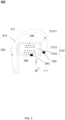
- FIG. 2 is a schematic diagram illustrating an exemplary ear according to some embodiments of the present disclosure.
- the ear 200 may include an external ear canal 201, a concha cavity 202, a cymba conchae 203, a triangular fossa 204, an antihelix 205, a scapha 206, a helix 207, an earlobe 208, and a helix feet 209.
- the wearing and stability of an earphone e.g., the earphone 100
- parts of the ear 200 such as the external ear canal 201, the concha cavity 202, the cymba conchae 203, the triangular fossa 204, etc., may be used to meet the wearing requirements of earphones because they have a certain depth and volume in a three-dimensional space.
- an open earphone e.g., the earphone 100
- parts of the ear 200 such as the cymba conchae 203, the triangular fossa 204, the antihelix 205, the scapha 206, or the like, or any combination thereof.
- the earlobe 208 of the user and other parts may also be further used.
- the wearing of the earphone and the transmission of mechanical vibrations may be achieved, and the external ear canal 201 of the user may be "liberated," thereby reducing the impact of the earphone on the health of the user's ear.
- the earphone may not block the user's external ear canal 201.
- the user may receive both sounds from the earphone and sounds from an environment (e.g., a sound of horn, a car bell, a sound of the surrounding people, a sound of a traffic command, etc.), thereby reducing a probability of a traffic accident.
- an environment e.g., a sound of horn, a car bell, a sound of the surrounding people, a sound of a traffic command, etc.
- a whole or part of the structure of the earphone may be located on the front side of the helix feet 209 (e.g., a region J enclosed by a dotted line in FIG. 2 ).
- the whole or part of the structure of the earphone may be in contact with an upper part of the external ear canal 201 (e.g., positions where one or more parts of the helix feet 209, the cymba conchae 203, the triangular fossa 204, the antihelix 205, the scapha 206, the helix 207, etc. are located).
- an upper part of the external ear canal 201 e.g., positions where one or more parts of the helix feet 209, the cymba conchae 203, the triangular fossa 204, the antihelix 205, the scapha 206, the helix 207, etc. are located.
- the whole or part of the structure of the earphone may be located in one or more parts (e.g., the concha cavity 202, the cymba conchae 203, the triangular fossa 204, etc.) of the ear (e.g., a region M enclosed by a dotted line in FIG. 2 ).
- the ear 200 is merely provided for the purpose of illustration, and is not intended to limit the scope of the present disclosure.
- a plurality of variations and modifications may be made under the teachings of the present disclosure.
- structures, shapes, sizes, thicknesses, etc. of the one or more parts of the ear 200 may be different.
- a part of the structure of the earphone may shield part or all of the external ear canal 201. Those variations and modifications do not depart from the scope of the present disclosure.
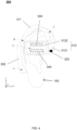
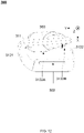
- FIG. 3 is a schematic structural diagram illustrating an exemplary earphone according to some embodiments of the present disclosure.
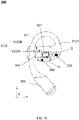
- FIG. 4 is a schematic diagram illustrating an exemplary earphone in a wearing state according to some embodiments of the present disclosure.
- the earphone 300 may include a fixing structure 310, a first microphone array 320, a processor 330, and a speaker 340.
- the first microphone array 320, the processor 330, and the speaker 340 may be located in the fixing structure 310.
- the fixing structure 310 may be configured to hang the earphone 300 near a user's ear without blocking an ear canal of the user.
- the fixing structure 310 may include a hook-shaped component 311 and a body part 312.
- the hook-shaped component 311 may include any shape suitable for the user to wear, such as a C shape, a hook shape, etc.
- the hook-shaped component 311 When the user wears the earphone 300, the hook-shaped component 311 may be hung between a first side of the ear and the head of the user.
- the body part 312 may include a connecting component 3121 and a holding component 3122.
- the connecting component 3121 may be configured to connect the hook-shaped component 311 and the holding component 3122.
- the holding component 3121 When the user wears the earphone 300, the holding component 3121 may contact a second side of the ear.
- the connecting component 3121 may extend from the first side of the ear to the second side of the ear. Both ends of the connecting component 3121 may be respectively connected to the hook-shaped component 311 and the holding component 3122.
- the connecting component 3121 may cooperate with the hook-shaped component 311 to provide the holding component 3121 with a pressing force on the second side of the ear.
- the connecting component 3121 may cooperate with the holding component 3122 to provide the hook-shaped component 311 with a pressing force on the first side of the ear.
- the connecting component 3121 may connect the hook-shaped component 311 and the holding component 3122, so that the fixing structure 310 may be curved in a three-dimensional space. It may also be understood that in the three-dimensional space, the hook-shaped component 311, the connecting component 3121, and the holding component 3122 may be not coplanar. In this arrangement, when the earphone 300 is in a wearing state, as shown in FIG.
- the hook-shaped component 311 may be hung between the first side of the ear 100 and the head of the user, and the holding component 3122 may contact the second side of the user's ear 100, so that the holding component 3122 and the hook-shaped component 311 may cooperate to clamp the ear.
- the connecting component 3121 may extend from the head to outside of the head (i.e., from the first side of the ear 100 to the second side of the ear), and then cooperate with the hook-shaped component 311 to provide the holding component 3122 with a pressing force on the second side of the ear 100.
- the connecting component 3121 may also cooperate with the holding component 3122 to provide the hook-shaped component 311 with a pressing force on the first side of the ear 100, so that the fixing structure 310 may clamp the user's ear 100 to realize the wearing of the earphone 300.
- the holding component 3122 may press against the ear under the action of the pressing force, for example, against a region where parts of the cymba conchae, the triangular fossa, the antihelix, etc., are located, so that the earphone 300 may not block the external ear canal of the ear when the earphone 300 is in the wearing state.
- a projection of the holding component 3122 on the user's ear may fall within a range of the helix of the ear.
- the holding component 3122 may be located at the side of the external ear canal of the ear close to a top of the user's head, and contact the helix and/or the antihelix. In this arrangement, on one hand, the holding component 3122 may be prevented from shielding the external ear canal, thereby not blocking the user's ear. At the same time, a contact area between the holding component 3122 and the ear may also be increased, thereby improving the wearing comfort of the earphone 300.
- the speaker 340 located at the holding component 3122 may be enabled to be closer to the user's ear canal, thereby improving the user's listening experience when using the earphone 300.
- the earphone 300 may also elastically clamp the ear.
- the hook-shaped component 311 of the earphone 300 may include an elastic component (not shown) connected to the connecting component 3121.
- the elastic component may have a certain elastic deformation capability, so that the hook-shaped component 311 may be deformed under the action of an external force, thereby generating a displacement relative to the holding component 3122 to allow the hook-shaped component 311 to cooperate with the holding component 3122 to elastically clamp the ear.
- the user may first force the hook-shaped component 311 to deviate from the holding component 3122, so that the ear may protrude between the holding component 3122 and the hook-shaped component 311. After a wearing position is appropriate, a hand may be released to allow the earphone 300 to elastically clamp the ear. The user may further adjust the position of the earphone 300 on the ear according to an actual wearing situation.
- the hook-shaped component 311 may be configured to be rotatable relative to the connecting component 3121
- the holding component 3122 may be configured to be rotatable relative to the connecting component 3121
- a portion of the connecting component 3121 may be configured to be rotatable relative to the other portion, so that a relative position relationship of the hook-shaped component 311, the connecting component 3121, and the holding component 3122 in the three-dimensional space may be adjusted, so that the earphone 300 can adapt to different users, that is, to increase an applicable scope of the earphone 300 for the users in terms of wearing.
- the relative position relationship of the hook-shaped component 311, the connecting component 3121, and the holding component 3122 in the three-dimensional space may be adjustable, and positions of the first microphone array 320 and the speaker 340 relative to the user's ear (e.g., the external ear canal) may also be adjusted, thereby improving the effect of active noise reduction of the earphone 300.
- the connecting component 3121 may be made of deformable material such as soft steel wires, etc. The user may bend the connecting component 3121 to rotate one portion relative to the other portion, so as to adjust the relative positions of the hook-shaped component 311, the connecting component 3121, and the holding component 3122 in the three-dimensional space, thereby meeting the wearing requirements of the user.
- the connecting component 3121 may also be provided with a rotating shaft mechanism 31211, through which the user may adjust the relative positions of the hook-shaped component 311, the connecting component 3121, and the holding component 3122 in the three-dimensional space to meet the wearing requirements of the user.
- the earphone 300 may estimate a sound field at the user's ear canal (e.g., a target spatial position) using the first microphone array 320 and the processor 330, and output a target signal using the speaker 340 to reduce environmental noise at the user's ear canal, thereby achieving active noise reduction of the earphone 300.
- the first microphone array 320 may be located in the body part 312 of the fixing structure 310, so that when the user wears the earphone 300, the first microphone array 320 may be located near the user's ear canal. The first microphone array 320 may pick up the environmental noise near the user's ear canal.
- the processor 330 may further estimate the environmental noise at the target spatial position according to the environmental noise near the user's ear canal, for example, the environmental noise at the user's ear canal.
- the target signal output by the speaker 340 may also be picked up by the first microphone array 320.
- the first microphone array 320 may be located in a region where an intensity of sound emitted by the speaker 340 is small or even the smallest in space, for example, an acoustic zero point position of a radiated sound field of an acoustic dipole formed by the earphone 300 (e.g. a sound outlet hole and a pressure relief hole).
- acoustic zero point position of a radiated sound field of an acoustic dipole formed by the earphone 300 e.g. a sound outlet hole and a pressure relief hole.
- the processor 330 may be located in the hook-shaped component 311 or the body part 312 of the fixing structure 310.
- the processor 330 may be electrically connected to the first microphone array 320.
- the processor 330 may estimate the sound field at the target spatial position based on the environmental noise picked up by the first microphone array 320, and generate a noise reduction signal based on the estimated sound field at the target spatial position.
- Detailed descriptions regarding the processor 330 estimating the sound field at the target spatial position using the first microphone array 320 may be found elsewhere (e.g., FIGs. 14-16 , and relevant descriptions thereof) in the present disclosure.
- the processor 330 may also be configured to control sound producing of the speaker 340.
- the processor 330 may control the sound producing of the speaker 340 according to an instruction input by the user.
- the processor 330 may generate the instruction to control the speaker 340 according to information of one or more components of the earphone 300.
- the processor 330 may control other components of the earphone 300 (e.g., a battery).
- the processor 330 may be disposed at any part of the fixing structure 310.
- the processor 330 may be disposed at the holding component 3122.
- a wiring distance between the processor 330 and other components (e.g., the speaker 340, a button switch, etc.) disposed at the holding component 3122 may be shortened, so as to reduce signal interference between the wirings and reduce a possibility of a short circuit between the wirings.
- the speaker 340 may be located in the holding component 3122 of the body part 312, so that when the user wears the earphone 300, the speaker 340 may be located near the user's ear canal.
- the speaker 340 may output, based on the noise reduction signal generated by the processor 330, the target signal.
- the target signal may be transmitted to the outside of the earphone 300 through a sound outlet hole (not shown) on the holding component 3122, which may be configured to reduce the environmental noise at the user's ear canal.
- the sound outlet hole on the holding component 3122 may be located on a side of the holding component 3122 facing the user's ear, so that the sound outlet hole may be close enough to the user's ear canal, and the sound emitted by the sound outlet hole may be better heard by the user.
- the earphone 300 may also include a component such as a battery 350, etc.
- the battery 350 may provide power for other components of the earphone 300 (e.g., the first microphone array 320, the speaker 340, etc.).
- any two of the first microphone array 320, the processor 330, the speaker 340, and the battery 350 may communicate in various ways, such as a wired connection, a wireless connection, or the like, or any combination thereof.
- the wired connection may include metal cables, optical cables, hybrid metal and optical cables, etc. The examples described above are merely for convenience of illustration.
- a medium of the wired connection may also be other types of transmission carriers, such as an electrical signal, an optical signal, etc.
- the wireless connection may include radio communication, free space light communication, acoustic communication, electromagnetic induction, etc.
- the battery 350 may be disposed at one end of the hook-shaped component 311 away from the connecting component 3121, and located between a rear side of the user's ear and the head when the user wears the earphone 300. In this arrangement, a capacity of the battery 350 may be increased and the battery life of the earphone 300 may be improved. Moreover, a weight of the earphone 300 may be balanced to overcome a self-weight of structures such as the holding component 3122 and the internal processor 330, the speaker 340, thereby improving the stability and comfort of the earphone 300 in wearing. In some embodiments, the battery 350 may also transmit its own state information to the processor 330 and receive an instruction of the processor 330 to perform a corresponding operation. The state information of the battery 350 may include an on/off state, a remaining power, a remaining power usage time, a charging time, or the like, or any combination thereof.
- One or more coordinate systems may be established in the present disclosure for the convenience of describing a relationship between various parts of an earphone (e.g., the earphone 300 ) and a relationship between the earphone and the user.
- an earphone e.g., the earphone 300
- three basic planes of a sagittal plane, a coronal plane, and a horizontal plane, and three basic axes of a sagittal axis, a coronal axis, and a vertical axis of a human body may be defined. See the coordinate axis in FIGs. 2-4 .
- the sagittal plane may refer to a plane perpendicular to the ground along a front-rear direction of the body, which divides the human body into left and right parts.
- the sagittal plane may refer to a YZ plane, that is, an X axis may be perpendicular to the sagittal plane of the user.
- the coronal plane may refer to a plane perpendicular to the ground along a left-right direction of the body, which divides the human body into front and rear parts.
- the coronal plane may refer to an XZ plane, that is, a Y axis may be perpendicular to the coronal plane of the user.
- the horizontal plane may refer to the a plane parallel to the ground along an upper-lower direction of the body, which divides the human body into upper and lower parts.
- the horizontal plane may refer to an XY plane, that is, a Z axis may be perpendicular to the horizontal plane of the user.
- the sagittal axis may refer to an axis that vertically passes through the coronal plane along the front-rear direction of the body.
- the sagittal axis may refer to the Y-axis.
- the coronal axis may refer to an axis that vertically passes through the sagittal plane along the left-right direction of the body.
- the coronal axis may refer to the X axis.
- the vertical axis may refer to an axis that vertically passes through the horizontal plane along the upper-lower direction of the body. In the embodiments of the present disclosure, the vertical axis may refer to the Z axis.
- FIG. 5 is a schematic structural diagram illustrating an exemplary earphone according to some embodiments of the present disclosure.
- FIG. 6 is a schematic diagram illustrating an exemplary earphone in a wearing state according to some embodiments of the present disclosure.
- the hook-shaped component 311 may be close to the holding component 3122, so that when the earphone 300 is in the wearing state as shown in FIG. 6 , a free end of the hook-shaped component 311 facing away from the connecting component 3121 may act on a first side (rear side) of the ear 100 of a user.
- the connecting component 3121 may be connected to the hook-shaped component 311.
- the connecting component 3121 and the hook-shaped component 311 may form a first connection point C.
- the hook-shaped component 311 may be bent towards the rear side of the ear 100 and form a first contact point B with the rear side of the ear 100.
- the holding component 3122 may form a second contact point F with the second side (front side) of the ear 100.
- a distance between the first contact point B and the second contact point F along an extension direction of the connecting component 3121 in the natural state may be smaller than a distance between the first contact point B and the second contact point F along the extension direction of the connecting component 3121 in the wearing state, thereby providing the holding component 3122 with a pressing force on the second side (front side) of the ear 100, and providing the hook-shaped component 311 with a pressing force on the first side (rear side) of the ear 100.
- the distance between the first contact point B and the second contact point F along the extension direction of the connecting component 3121 is smaller than a thickness of the user's ear 100, so that the earphone 300 may be clamped to the user's ear 100 like a "clip" in the wearing state.
- the hook-shaped component 311 may also extend in a direction away from the connecting component 3121, that is, to extend an overall length of the hook-shaped component 311, so that when the earphone 300 is in the wearing state, the hook-shaped component 311 may also form a third contact point A with the rear side of the ear 100.
- the first contact point B may be located between the first connection point C and the third contact point A, and close to the first connection point C.
- a distance between projections of the first contact point B and the third contact point A on a reference plane (e.g., the YZ plane) perpendicular to an extension direction of the connecting component 3121 in the natural state may be smaller than a distance between projections of the first contact point B and the third contact point A on the reference plane (e.g., the YZ plane) perpendicular to an extension direction of the connecting component 3121 in the wearing state.
- a reference plane e.g., the YZ plane
- the free end of the hook-shaped component 311 may be pressed against the rear side of the user's ear 100, so that the third contact point A may be located in a region of the ear 100 close to the earlobe, and the hook-shaped component 311 may further clamp the user's ear in a vertical direction (Z-axis direction) to overcome a self-weight of the holding component 3122.
- a contact area between the hook-shaped component 311 and the user's ear 100 may be increased while the hook-shaped component 311 clamps the user's ear 100 in the vertical direction, that is, a friction force between the hook-shaped component 311 and the user's ear 100 may be increased, thereby improving the wearing stability of the earphone 300.
- a connecting component 3121 may be provided between the hook-shaped component 311 and the holding component 3122 of the earphone 300, so that when the earphone 300 is in the wearing state, the connecting component 3121 may cooperate with the hook-shaped component 311 to provide the holding component 3122 with a pressing force on the first side of the ear. Therefore, the earphone 300 may be firmly attached to the user's ear when the earphone 300 is in the wearing state, thereby improving the stability of the earphone 300 in wearing and the reliability of the earphone 300 in sound production.
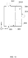
- FIG. 7 is a structural diagram illustrating an exemplary earphone according to some embodiments of the present disclosure.
- FIG. 8 is a schematic diagram illustrating an exemplary earphone in a wearing state according to some embodiments of the present disclosure.
- the earphone 300 shown in FIGs. 7-8 may be similar to the earphone 300 shown in FIGs. 5-6 , and a difference may lie in that a bending direction of the hook-shaped component 311 is different.
- the hook-shaped component 311 in the direction from the first connection point C between the hook-shaped component 311 and the connecting component 3121 to the free end of the hook-shaped component 311 (an end away from the connecting component 3121), the hook-shaped component 311 may be bent towards the user's head, and form the first contact point B and the third contact point A with the head.
- the first contact point B may be located between the third contact point A and the first connection point C.
- the hook-shaped component 311 may form a lever structure with the first contact point B as a fulcrum. At this time, the free end of the hook-shaped component 311 may press against the user's head, and the user's head may provide a force directed towards outside of the head at the third contact point A. The force may be converted by the lever structure into a force directed at the head at the first connection point C, thereby providing the holding component 3122 with a pressing force on the first side of the ear 100 via the connecting component 3121.
- the magnitude of the force directed towards the outside of the user's head at the third contact point A may be positively related to the magnitude of an included angle formed by the free end of the hook-shaped component 311 and the YZ plane when the earphone 300 is in the non-wearing state.
- the larger the included angle formed between the free end of the hook-shaped component 311 and the YZ plane when the earphone 300 is in the non-wearing state the better the free end of the hook-shaped component 311 may press against the user's head when the earphone 300 is in the wearing state, and the greater the force that the user's head may provide at the third contact point A directed towards the outside of the head.
- the included angle formed between the free end of the hook-shaped component 311 and the YZ plane when the earphone 300 is in the non-wearing state may be greater than the included angle formed between the free end of the hook-shaped component 311 and the YZ plane when the earphone 300 is in the wearing state.
- another pressing force may be formed on at least the first side of the ear 100 by the hook-shaped component 311, and may cooperate with the pressing force formed by the holding component 3122 on the second side of the ear 100 to form a pressing effect of "front and rear clamping" on the user's ear 100, thereby improving the stability of the earphone 300 in wearing.
- the actual wearing of the earphone 300 may be affected to a certain extent, and a position of the contact point (e.g., the first contact point B, the second contact point F, the third contact point A, etc.) between the earphone 300 and the user's head or ear may change accordingly.
- the contact point e.g., the first contact point B, the second contact point F, the third contact point A, etc.
- the actual wearing of the earphone 300 may be affected to a certain extent due to the differences in the physiological structures such as heads, ears, etc., of different users. Therefore, when different users wear the earphone 300, a relative position relationship of the speaker 340 and the user's ear may change.
- the position of the speaker 340 on the overall structure of the earphone 300 may be adjusted, thereby adjusting a distance of the speaker 340 relative to the user's ear canal.
- FIG. 9A is a structural diagram illustrating an exemplary earphone according to some embodiments of the present disclosure.
- FIG. 9B is a structural diagram illustrating an exemplary earphone according to some embodiments of the present disclosure.
- the holding component 3122 may be designed as a multi-segment structure to adjust a relative position of the speaker 340 on the overall structure of the earphone 300.
- the holding component 3122 may be a multi-segment structure, which may make the earphone 300 in the wearing state without blocking the external ear canal of the ear, and at the same time, may make the speaker 340 as close to the external ear canal as possible to improve the user's listening experience when using the earphone 300.
- the holding component 3122 may include a first holding segment 3122-1, a second holding segment 3122-2, and a third holding segment 3122-3 that are connected end to end in sequence.
- One end of the first holding segment 3122-1 facing away from the second holding section 3122-2 may be connected to the connecting component 3121, and the second holding segment 3122-2 may be folded back relative to the first holding segment 3122-1, so that the second holding segment 3122-2 and the first holding segment 3122-1 may have a distance.
- the second holding segment 3122-2 and the first holding segment 3122-1 may have a U-shaped structure.
- the third holding segment 3122-3 may be connected to an end of the second holding segment 3122-2 facing away from the first holding segment 3122-1.
- the third holding segment 3122-3 may be configured to dispose a structural component such as the speaker 340, etc.
- a position of the third holding segment 3122-3 on the overall structure of the earphone 300 may be adjusted by adjusting the distance between the second holding segment 3122-2 and the first holding segment 3122-1, a folded back length of the second holding segment 3122-2 relative to the first holding segment 3122-1 (a length of the second holding segment 3122-2 along the Y-axis direction), etc., thereby adjusting a position or a distance of the speaker 340 located on the third holding segment 3122-3 relative to the user's ear canal.
- the distance between the second holding segment 3122-2 and the first holding segment 3122-1, and the folded back length of the second holding segment 3122-2 relative to the first holding segment 3122-1 may be set according to ear characteristics (e.g., shape, size, etc.) of different users, which will not be limited specifically herein.
- the holding component 3122 may include the first holding segment 3122-1, the second holding segment 3122-2, and the third holding segment 3122-2 that are connected end to end in sequence.
- One end of the first holding segment 3122-1 facing away from the second holding segment 3122-2 may be connected to the connecting component 3121, and the second holding segment 3122-2 may be bent relative to the first holding segment 3122-1, so that the third holding segment 3122-3 and the first holding segment 3122-1 may have a distance.
- a structural component, such as the speaker 340, etc., may be disposed on the third holding segment 3122-3.
- a position of the third holding segment 3122-3 on the overall structure of the earphone 300 may be adjusted by adjusting the distance between the third holding segment 3122-3 and the first holding segment 3122-1, abending the length of the second holding segment 3122-2 relative to the first holding segment 3122-1 (a length of the second holding section 3122-2 along the Z-axis direction), etc., thereby adjusting a position or a distance of the speaker 340 located on the third holding segment 3122-3 relative to the user's ear canal.
- the distance between the third holding segment 3122-3 and the first holding segment 3122-1, and the bending length of the second holding segment 3122-2 relative to the first holding segment 3122-1 may be set according to ear characteristics (e.g., shape, size, etc.) of different users, which will not be limited specifically herein.
- FIG. 10 is a structural diagram illustrating a side of an exemplary earphone facing an ear according to some embodiments of the present disclosure.
- a sound outlet hole 301 may be provided on a side of the holding component 3122 facing the ear, so that a target signal output by the speaker 340 may be transmitted to the ear through the sound outlet hole 301.
- the side of the holding component 3122 facing the ear may include a first region 3122A and a second region 3122B.
- the second region 3122B may be farther away from the connecting component 3121 than the first region 3122A. That is, the second region 3122B may be located at the free end of the holding component 3122 away from the connecting component 3121.
- the first region 3122A may be provided with the sound outlet hole 301.
- the second region 3122B may protrude toward the ear relative to the first region 3122A, so that the second region 3122B may be brought into contact with the ear to allow the sound outlet hole 301 to be spaced from the ear in the wearing state.
- the free end of the holding component 3122 may be configured as a convex hull structure, and on the side surface of the holding component 3122 close to the user's ear, the convex hull structure may protrude outwards (i.e., toward the user's ear) relative to the side surface. Since the speaker 340 can generate a sound (e.g., the target signal) transmitted to the ear through the sound outlet hole 301, the convex hull structure may prevent the ear from blocking the sound outlet hole 301 and the sound produced by the speaker 340 may be weakened or even may not be output.
- a sound e.g., the target signal
- a protrusion height of the convex hull structure in a thickness direction (the X-axis direction) of the holding component 3122, may be represented by a maximum protrusion height of the second region 3122B relative to the first region 3122A. In some embodiments, the maximum protrusion height of the second region 3122B relative to the first region 3122A may be greater than or equal to 1 mm. In some embodiments, in the thickness direction of the holding component 3122, the maximum protrusion height of the second region 3122B relative to the first region 3122A may be greater than or equal to 0.8 mm. In some embodiments, in the thickness direction of the holding component 3122, the maximum protrusion height of the second region 3122B relative to the first region 3122A may be greater than or equal to 0.5 mm.
- a distance between the sound outlet hole 301 and the user's ear canal may be less than 10 mm when the user wears the earphone 300. In some embodiments, by setting the structure of the holding component 3122, a distance between the sound outlet hole 301 and the user's ear canal may be less than 8 mm when the user wears the earphone 300. In some embodiments, by setting the structure of the holding component 3122, a distance between the sound outlet hole 301 and the user's ear canal may be less than 7 mm when the user wears the earphone 300. In some embodiments, by setting the structure of the holding component 3122, a distance between the sound outlet hole 301 and the user's ear canal may be less than 6 mm when the user wears the earphone 300.
- a region protrudes more toward the ear than with the first region 3122A may also be located in other regions of the holding component 3122, such as a region between the sound outlet hole 301 and the connecting component 3121.
- an orthographic projection of the sound outlet hole 301 on the ear along the thickness direction of the holding component 3122 may at least partially fall within the concha cavity and/or the cymba concha.
- the holding component 3122 may be located on the side of the ear hole close to the top of the user's head and contact with the helix. At this time, the orthographic projection of the sound outlet hole 301 on the ear along the thickness direction of the holding component 3122 may at least partially fall within the cymba concha.
- FIG. 11 is a structural diagram illustrating a side of an exemplary earphone facing away from an ear according to some embodiments of the present disclosure.
- FIG. 12 is a top view illustrating an exemplary earphone according to some embodiments of the present disclosure.
- a pressure relief hole 302 may be provided on a side of the holding component 3122 along a vertical axis direction (the Z-axis) and close to a top of the user's head, and the pressure relief hole may be farther away from the user's ear canal than the sound outlet hole 301.
- an opening direction of the pressure relief hole 302 may face the top of the user's head, and there may be a specific included angle between the opening direction of the pressure relief hole 302 and the vertical axis (the Z-axis) to allow the pressure relief hole 302 to be farther away from the user's ear canal, thereby making it difficult for the user to hear the sound output through the pressure relief hole 302 and transmitted to the user's ear.
- the included angle between the opening direction of the pressure relief hole 302 and the vertical axis (the Z-axis) may be in a range of 0° to 10°.
- the included angle between the opening direction of the pressure relief hole 302 and the vertical axis may be in a range of 0° to 8°. In some embodiments, the included angle between the opening direction of the pressure relief hole 302 and the vertical axis (the Z-axis) may be in a range of 0° to 5°.
- a distance between the pressure relief hole 302 and the user's ear canal may be within an appropriate range when the user wears the earphone 300. In some embodiments, when the user wears the earphone 300, the distance between the pressure relief hole 302 and the user's ear canal may be in a range of 5 mm to 20 mm. In some embodiments, when the user wears the earphone 300, the distance between the pressure relief hole 302 and the user's ear canal may be in a range of 5 mm to 18 mm.
- the distance between the pressure relief hole 302 and the user's ear canal may be in a range of 5 mm to 15 mm. In some embodiments, when the user wears the earphone 300, the distance between the pressure relief hole 302 and the user's ear canal may be in a range of 6 mm to 14 mm. In some embodiments, when the user wears the earphone 300, the distance between the pressure relief hole 302 and the user's ear canal may be in a range of 8 mm to 10 mm.
- FIG. 13 is a schematic diagram illustrating a cross-sectional structure of an exemplary earphone according to some embodiments of the present disclosure.
- FIG. 13 shows an acoustic structure formed by a holding component (e.g., the holding component 3122 ) of the earphone (e.g., the earphone 300).
- the acoustic structure includes the sound outlet hole 301, the pressure relief hole 302, a sound adjustment hole 303, a front cavity 304, and a rear cavity 305.
- the holding component 3122 may respectively form the front cavity 304 and the rear cavity 305 on opposite sides of the speaker 340.
- the front cavity 304 may be connected with outside of the earphone 300 through the sound outlet hole 301, and output sound (e.g., a target signal, an audio signal, etc.) to an ear.
- the rear cavity 305 may be connected with outside of the earphone 300 through the pressure relief hole 302, and the pressure relief hole 302 may be farther away from the user's ear canal than the sound outlet hole 301.
- the pressure relief hole 302 may allow air to freely flow in and out of the rear cavity 305 so that changes in air pressure in the front cavity 304 may not be blocked by the rear cavity 305 as much as possible, thereby improving sound quality of the sound output to the ear through the sound outlet hole 301.
- an included angle between a thickness direction (the X-axis direction) of the holding component 3122 and a connection line between the pressure relief hole 302 and the sound outlet hole 301 may be in a range of 0° to 50°. In some embodiments, the included angle between the thickness direction (the X-axis direction) of the holding component 3122 and the connection line between the pressure relief hole 302 and the sound outlet hole 301 may be in a range of 5° to 45°. In some embodiments, the included angle between the thickness direction (the X-axis direction) of the holding component 3122 and the connection line between the pressure relief hole 302 and the sound outlet hole 301 may be in a range of 10° to 40°.
- the included angle between the thickness direction (the X-axis direction) of the holding component 3122 and the connection line between the pressure relief hole 302 and the sound outlet hole 301 may be in a range of 15 ° to 35 °. It should be noted that the included angle between the thickness direction of the holding component and the connection line between the pressure relief hole and the sound outlet hole may be an included angle between the thickness direction of the holding component 3122 and a connection line between a center of the pressure relief hole 302 and a center of the sound outlet hole 301.
- the sound outlet hole 301 and the pressure relief hole 302 may be regarded as two sound sources that radiate sounds outward, and the radiated sounds have the same amplitude and opposite phases.
- the two sound sources may approximately form an acoustic dipole or may be similar to an acoustic dipole, so the sound radiated outward may have obvious directivity, forming a "8"-shaped sound radiation region.
- the sound radiated by the two sound sources may be the loudest, and the sound radiated in other directions may be significantly reduced.
- the sound radiated at a mid-perpendicular line of the connecting line between the two sound sources may be the lightest.
- the sound radiated by the pressure relief hole 302 and the sound outlet hole 301 may be the loudest, and the sound radiated in other directions may be significantly reduced.
- the sound radiated at a mid-perpendicular line of the connecting line between the pressure relief hole 302 and the sound outlet hole 301 may be the lightest.
- the acoustic dipole formed by the pressure relief hole 302 and the sound outlet hole 301 may reduce the sound leakage of the speaker 340.
- the holding component 3122 may also be provided with the sound adjustment hole 303 connected to the rear cavity 305.
- the sound adjustment hole 303 may be configured to destroy a high pressure region of a sound field in the rear cavity 305, so that a wavelength of a standing wave in the rear cavity 305 may be shortened, and a resonance frequency of a sound output to outside of the earphone 300 through the pressure relief hole 302 may be made as high as possible, for example, greater than 4 kHz, so as to reduce the sound leakage of the speaker 340.
- the sound adjustment hole 303 and the pressure relief hole 302 may be located on opposite sides of the speaker 340, for example, the sound adjustment hole 303 and the pressure relief hole 302 may be disposed opposite to each other in the Z-axis direction, so as to destroy the high pressure region of the sound field in the rear cavity 305 to the greatest extent.
- the sound adjustment hole 303 may be farther away from the sound outlet hole 301, so as to increase a distance between the sound adjustment hole 303 and the sound outlet hole 301 as much as possible, thereby reducing inversion cancellation between the sound output from the sound adjustment hole 303 to the outside of the earphone 300 and the sound transmitted to the ear through the sound outlet hole 301.
- a target signal output by the speaker 340 through the sound outlet hole 301 and/or the pressure relief hole 302 may also be picked up by the first microphone array 320.
- the target signal may affect the estimation of a sound field at a target spatial position by the processor 330, that is, the target signal output by the speaker 340 may not be expected to be picked up.
- the first microphone array 320 may be disposed in a first target region where sound output by the speaker 340 is as light as possible.
- the first target region may be or near an acoustic zero point position of a radiated sound field of the acoustic dipole formed by the pressure relief hole 302 and the sound outlet hole 301.
- the first target region may be a region G shown in FIG. 10 .
- the region G may be located in front of the sound outlet hole 301 and/or the pressure relief hole 302 (the front here may refer to a direction the user faces), that is, the region G may be relatively close to the user's eyes.
- the region G may be a partial region on the connecting component 3121 of the fixing structure 310. That is, the first microphone array 320 may be located in the connecting component 3121.
- the first microphone array 320 may be located at a position of the connecting component 3121 that is close to the holding component 3122.
- the region G may also be located behind the sound outlet hole 301 and/or the pressure relief hole 302 (the behind here may refer to a direction opposite to the direction the user faces).
- the region G may be located on an end of the holding component 3122 away from the connecting component 3121.
- a relative position relationship between the first microphone array 320 and the sound outlet hole 301 and/or the pressure relief hole 302 may be reasonably disposed.
- the position of the first microphone array 320 here may be a position where any microphone in the first microphone array 320 is located.
- a first included angle may be formed between a connection line between the first microphone array 320 and the sound outlet hole 301 and a connection line between the sound outlet hole 301 and the pressure relief hole 302.
- a second included angle may be formed between a connection line between the first microphone array 320 and the pressure relief hole 302 and the connection line between the sound outlet hole 301 and the pressure relief hole 302.
- a difference between the first included angle and the second included angle may be less than or equal to 30°.
- the difference between the first included angle and the second included angle may be less than or equal to 25°.
- the difference between the first included angle and the second included angle may be less than or equal to 20°.
- the difference between the first included angle and the second included angle may be less than or equal to 15°.
- the difference between the first included angle and the second included angle may be less than or equal to 10°.
- a distance between the first microphone array 320 and the sound outlet hole 301 may be a first distance.
- a distance between the first microphone array 320 and the pressure relief hole 302 may be a second distance.
- a difference between the first distance and the second distance may be less than or equal to 6 mm.
- the difference between the first distance and the second distance may be no more than 5 mm.
- the difference between the first distance and the second distance may be less than or equal to 4 mm.
- the difference between the first distance and the second distance may be less than or equal to 3 mm.
- a position relationship between the first microphone array 320 and the sound outlet hole 301 and/or the pressure relief hole 302 described herein may refer to a position relationship between any microphone in the first microphone array 320 and the center of the sound outlet hole 301 and/or the center of the pressure relief hole 302.
- the first included angle formed by the connection line between the first microphone array 320 and the sound outlet hole 301 and the connection line between the sound outlet hole 301 and the pressure relief hole 302 may refer to a first included angle formed by a connection line between any microphone in the first microphone array 320 and the center of the sound outlet hole 301 and a connection line between the center of the sound outlet hole 301 and the center of the pressure relief hole 302.
- the first distance between the first microphone array 320 and the sound outlet hole 301 may refer to a first distance between any microphone in the first microphone array 320 and the center of the sound outlet hole 301.
- the first microphone array 320 may be disposed at the acoustic zero point position of the acoustic dipole formed by the sound outlet hole 301 and the pressure relief hole 302, so that the first microphone array 320 may be minimally affected by the target signal output by the speaker 340, and the first microphone array 320 may pick up the environmental noise near the user's ear canal with an improved accuracy. Further, the processor 330 may more accurately estimate the environmental noise at the user's ear canal based on the environmental noise picked up by the first microphone array 320 and generate a noise reduction signal, thereby better implementing the active noise reduction of the earphone 300. Detailed description regarding the active noise reduction of the earphone 300 using the first microphone array 320 may be found in FIGs. 14-16 , and relevant descriptions thereof.
- FIG. 14 is a flowchart illustrating an exemplary process for reducing noise of an earphone according to some embodiments of the present disclosure.
- the process 1400 may be performed by the earphone 300.
- the process 1400 may include the following operations.
- environmental noise may be picked up.
- the operation may be performed by the first microphone array 320.
- the environmental noise may refer to a combination of various external sounds (e.g., a traffic noise, an industrial noise, a building construction noise, a social noise) in an environment where a user is located.
- the first microphone array 320 located near the body part 312 of the earphone 300 and close to the user's ear canal may be configured to pick up the environmental noise near the user's ear canal. Further, the first microphone array 320 may convert a picked-up environmental noise signal into an electrical signal and transmit the electrical signal to the processor 330 for processing.
- noise at a target spatial position may be estimated based on the picked-up environmental noise.
- the operation may be performed by the processor 330.
- the processor 330 may perform a signal separation operation on the picked-up environmental noise.
- the environmental noise picked up by the first microphone array 320 may include various sounds.
- the processor 330 may perform a signal analysis operation on the environmental noise picked up by the first microphone array 320 to separate the various sounds.
- the processor 330 may adaptively adjust parameters of a filter according to statistical distribution characteristics and structural characteristics of various sounds in different dimensions such as space, time, frequency, etc.
- the processor 330 may estimate parameter information of each sound signal in the environmental noise, and perform the signal separation operation according to the parameter information of each sound signal.
- the statistical distribution characteristics of noise may include a probability distribution density, a power spectral density, a autocorrelation function, a probability density function, a variance, a mathematical expectation, etc.
- the structural characteristics of noise may include a noise distribution, a noise intensity, a global noise intensity, a noise rate, etc., or any combination thereof.
- the global noise intensity may refer to an average noise intensity or a weighted average noise intensity.
- the noise rate may refer to a degree of dispersion of the noise distribution.
- the environmental noise picked up by the first microphone array 320 may include a first signal, a second signal, and a third signal.
- the processor 330 may obtain differences among the first signal, the second signal, and the third signal in space (e.g., a position where the signals are located), time domain (e.g., delay), and frequency domain (e.g., amplitude, phase), and separate the first signal, the second signal, and the third signal according to the differences in the three dimensions to obtain relatively pure first signal, second signal, and third signal. Further, the processor 330 may update the environmental noise according to the parameter information (e.g., frequency information, phase information, amplitude information) of the separated signals. For example, the processor 330 may determine that the first signal is a user's call sound according to the parameter information of the first signal, and remove the first signal from the environmental noise to update the environmental noise. In some embodiments, the removed first signal may be transmitted to a far end associated with the call. For example, when the user wears the earphone 300 for a voice call, the first signal may be transmitted to the far end associated with the call.
- the parameter information e.g., frequency information, phase information
- the target spatial position may be a position determined based on the first microphone array 320 at or near the user's ear canal.
- the target spatial position may refer to a spatial position close to the user's ear canal (e.g., an earhole) at a certain distance (e.g., 2 mm, 3 mm, 5 mm, etc.).
- the target spatial position may be closer to the user's ear canal than any microphone in the first microphone array 320.
- the target spatial position may be related to a count of microphones in the first microphone array 320 and their distribution positions relative to the user's ear canal.
- the target spatial position may be adjusted by adjusting the count of the microphones in the first microphone array 320 and/or their distribution positions relative to the user's ear canal.
- the processor 330 may determine one or more spatial noise sources associated with the picked-up environmental noise, and estimate the noise at the target spatial position based on the spatial noise sources.
- the environmental noise picked up by the first microphone array 320 may come from different azimuths and different types of spatial noise sources. Parameter information (e.g., frequency information, phase information, amplitude information) corresponding to each spatial noise source may be different.
- the processor 330 may perform the signal separation and extraction on the noise at the target spatial location according to statistical distribution and structural characteristics of different types of noise in different dimensions (e.g., spatial domain, time domain, frequency domain, etc.), thereby obtaining different types (e.g., different frequencies, different phases, etc.) of noises, and estimate the parameter information (e.g., amplitude information, phase information, etc.) corresponding to each noise.
- the processor 330 may also determine overall parameter information of the noise at the target spatial position according to the parameter information corresponding to different types of noise at the target spatial position. More descriptions regarding estimating the noise at the target spatial position based on one or more spatial noise sources may be found elsewhere in the present disclosure (e.g., FIG. 15 and relevant descriptions thereof).
- the processor 330 may further construct a virtual microphone based on the first microphone array 320, and estimate the noise at the target spatial position based on the virtual microphone. More descriptions regarding the estimating the noise at the target spatial position based on the virtual microphone may be found elsewhere in the present disclosure (e.g., FIG. 16 and relevant descriptions thereof).
- a noise reduction signal may be generated based on the noise at the target spatial position.
- the operation may be performed by the processor 330.
- the processor 330 may generate the noise reduction signal based on the parameter information (e.g., amplitude information, phase information, etc.) of the noise at the target spatial position obtained in operation 1420.
- a phase difference between a phase of the noise reduction signal and a phase of the noise at the target spatial position may be less than or equal to a preset phase threshold.
- the preset phase threshold may be within a range of 90 degrees-180 degrees. The preset phase threshold may be adjusted within the range according to the user's needs.
- the preset phase threshold when the user does not want to be disturbed by sound of a surrounding environment, the preset phase threshold may be a larger value, such as 180 degrees, that is, the phase of the noise reduction signal may be opposite to the phase of the noise at the target spatial position.
- the preset phase threshold when the user wants to be sensitive to the surrounding environment, the preset phase threshold may be a smaller value, such as 90 degrees. It should be noted that if the user wants to receive more sound of the surrounding environment, the preset phase threshold may be set to be closer to 90 degrees; and if the user wants to receive less sound of the surrounding environment, the preset phase threshold may be set to be close to 180 degrees.
- an amplitude difference between an amplitude of the noise at the target spatial position and an amplitude of the noise reduction signal may be less than or equal to a preset amplitude threshold.
- the preset amplitude threshold may be a small value, such as 0 dB, that is, the amplitude of the noise reduction signal may be equal to the amplitude of the noise at the target spatial position.
- the preset amplitude threshold when the user wants to be sensitive to the surrounding environment, the preset amplitude threshold may be a relatively large value, for example, approximately equal to the amplitude of the noise at the target spatial position. It should be noted that, if the user wants to receive more sound of the surrounding environment, the preset amplitude threshold may be set to be closer to the amplitude of the noise at the target spatial position, and if the user wants to receive more sound of the surrounding environment, the preset amplitude threshold may be set to be closer to 0 dB.
- the speaker 340 may output, based on the noise reduction signal generated by the processor 330, a target signal.
- the speaker 340 may convert the noise reduction signal (e.g., an electrical signal) into the target signal (i.e., a vibration signal) based on a vibration component thereof.
- the target signal may be transmitted to the user's ear through the sound outlet hole 301 on the earphone 300, and cancel out the environmental noise at the user's ear canal.
- the speaker 340 may output target signals corresponding to the plurality of spatial noise sources based on the noise reduction signal.
- the plurality of spatial noise sources may include a first spatial noise source and a second spatial noise source.
- the speaker 340 may output a first target signal having an approximately opposite phase and approximately equal amplitude to noise of the first spatial noise source to cancel out the noise of the first spatial noise source, and output a second target signal having an approximately opposite phase and approximately equal amplitude to noise of the second spatial noise source to cancel out the noise of the second spatial noise source.
- a position where the target signal cancels out the environmental noise may be the target spatial position.
- a distance between the target spatial position and the user's ear canal is relatively small, and the noise at the target spatial position may be approximately regarded as the noise at the user's ear canal.
- the mutual cancellation of the noise reduction signal and the noise at the target spatial position may be approximated as the cancellation of the environmental noise transmitted to the user's ear canal, thereby realizing the active noise reduction of the earphone 300.
- a position where the target signal cancels out the environmental noise may be a basilar membrane.
- the target signal and the environmental noise may be canceled out at the basilar membrane of the user, thereby realizing the active noise reduction of the earphone 300.
- the earphone 300 may also include one or more sensors, which may be located anywhere on the earphone 300, e.g., the hook-shaped component 311, the connecting component 3121, and/or the holding component 3122.
- the one or more sensors may be electrically connected to other components of the earphone 300 (e.g., the processor 330). In some embodiments, the one or more sensors may be configured to obtain a physical position and/or motion information of the earphone 300.
- the one or more sensors may include an inertial measurement unit (IMU), a global positioning system (GPS), a Radar, etc.
- the motion information may include a motion trajectory, a motion direction, a motion speed, a motion acceleration, a motion angular velocity, a motion-related time information (e.g., a motion start time, a motion end time), or the like, or any combination thereof.
- the IMU may include a micro electro mechanical system (MEMS).
- MEMS micro electro mechanical system
- the MEMS may include a multi-axis accelerometer, a gyroscope, a magnetometer, or the like, or any combination thereof.
- the IMU may be configured to detect the physical position and/or the motion information of the earphone 300 to realize the control of the earphone 300 based on the physical position and/or the motion information.
- the processor 330 may update the noise at the target spatial position and the estimated sound field at the target spatial position based on the motion information (e.g., the motion trajectory, the motion direction, the motion speed, the motion acceleration, the motion angular velocity, the motion-related time information) of the earphone 300 obtained by the one or more sensors of the earphone 300. Further, the processor 330 may generate, based on the updated noise at the target spatial position and the updated estimated sound field at the target spatial position, the noise reduction signal.
- the motion information e.g., the motion trajectory, the motion direction, the motion speed, the motion acceleration, the motion angular velocity, the motion-related time information
- the one or more sensors may record the motion information of the earphone 300, and then the processor 330 may quickly update the noise reduction signal, which can improve noise tracking performance of the earphone 300, so that the noise reduction signal can more accurately eliminate the environmental noise, and further improve the noise reduction effect and the user's listening experience.
- FIG. 15 is a flowchart illustrating an exemplary process for estimating noise at a target spatial position according to some embodiments of the present disclosure. As shown in FIG. 15 , the process 1500 may include the following operations.
- one or more spatial noise sources associated with environmental noise picked up by the first microphone array 320 may be determined.
- the operation may be performed by the processor 330.
- determining a spatial noise source may refer to determining information about the spatial noise source, such as a position of the spatial noise source (including an orientation of the spatial noise source, a distance between the spatial noise source and the target spatial position, etc.), a phase of the spatial noise source, an amplitude of the spatial noise source, etc.
- the spatial noise source associated with environmental noise may refer to a noise source whose sound waves can be delivered to the user's ear canal (e.g., the target spatial position) or close to the user's ear canal.
- the spatial noise source may be a noise source from different directions (e.g., front, rear, etc.) of the user's body. For example, there may be a crowd noise in front of the user's body and a vehicle whistle noise on the left side of the user's body.
- the spatial noise source may include a crowd noise source in front of the user's body and a vehicle whistle noise source to the left of the user's body.
- the first microphone array 320 may pick up a spatial noise in all directions of the user's body, convert the spatial noise into an electrical signal, and transmit the electrical signal to the processor 330.
- the processor 330 may obtain parameter information (e.g., frequency information, amplitude information, phase information, etc.) of the picked-up spatial noise in various directions by analyzing the electrical signal corresponding to the spatial noise.
- the processor 330 may determine information (e.g., the orientation of the spatial noise source, a distance of the spatial noise source, a phase of the spatial noise source, an amplitude of the spatial noise source, etc.) of the spatial noise source in various directions according to the parameter information of the spatial noise in various directions.
- the processor 330 may determine the spatial noise source through a noise positioning algorithm based on the spatial noise picked up by the first microphone array 320.
- the noise positioning algorithm may include a beamforming algorithm, a super-resolution spatial spectrum estimation algorithm, a time difference of arrival algorithm (also referred to as a delay estimation algorithm), or the like, or any combination thereof.
- the processor 330 may divide the picked-up environmental noise into a plurality of frequency bands according to a specific frequency band width (e.g., each 500 Hz as a frequency band). Each frequency band may correspond to a different frequency range. In at least one frequency band, a spatial noise source corresponding to the frequency band may be determined. For example, the processor 330 may perform signal analysis on the frequency bands divided from the environmental noise, obtain parameter information of the environmental noise corresponding to each frequency band, and determine the spatial noise source corresponding to each frequency band according to the parameter information.
- a specific frequency band width e.g., each 500 Hz as a frequency band.
- Each frequency band may correspond to a different frequency range.
- a spatial noise source corresponding to the frequency band may be determined.
- the processor 330 may perform signal analysis on the frequency bands divided from the environmental noise, obtain parameter information of the environmental noise corresponding to each frequency band, and determine the spatial noise source corresponding to each frequency band according to the parameter information.
- noise at a target spatial position may be estimated based on the spatial noise sources.
- the operation may be performed by the processor 330.
- the estimating the noise at the target spatial position may refer to estimating parameter information of the noise at the target spatial position, such as frequency information, amplitude information, phase information, etc.
- the processor 330 may respectively estimate parameter information of a noise transmitted by each spatial noise source to the target spatial position based on the parameter information (e.g., the frequency information, the amplitude information, the phase information, etc.) of the spatial noise sources located in various directions of the user's body obtained in the operation 1510, thereby estimating the noise at the target spatial position. For example, there is a spatial noise source in a first orientation (e.g., front) and a second orientation (e.g., rear) of the user's body, respectively.
- a first orientation e.g., front
- a second orientation e.g., rear
- the processor 330 may estimate frequency information, phase information, or amplitude information of the first orientation spatial noise source when the noise of the first orientation spatial noise source is transmitted to the target spatial position according to the position information, the frequency information, the phase information, or the amplitude information of the first orientation spatial noise source.
- the processor 330 may estimate frequency information, phase information, or amplitude information of the second orientation spatial noise source when the noise of the second orientation spatial noise source is transmitted to the target spatial position according to the position information, the frequency information, the phase information, or the amplitude information of the second orientation spatial noise source.
- the processor 330 may estimate the noise information of the target spatial position based on the frequency information, the phase information, or the amplitude information of the first orientation spatial noise source and the second orientation spatial noise source, thereby estimating the noise information of the target spatial position.
- the processor 330 may estimate the noise information of the target spatial location using a virtual microphone technology or other techniques.
- the processor 330 may extract the parameter information of the noise of the spatial noise source from a frequency response curve of the spatial noise source picked up by the microphone array through a feature extraction technique.
- the technique for extracting the parameter information of the noise of the spatial noise source may include, but is not limited to, a principal components analysis (PCA) technique, an independent component algorithm (ICA), a linear discriminant analysis (LDA) technique, a singular value decomposition (SVD) technique, etc.
- PCA principal components analysis
- ICA independent component algorithm
- LDA linear discriminant analysis
- SMD singular value decomposition
- process 1500 is merely provided for the purpose of illustration, and is not intended to limit the scope of the present disclosure.
- process 1500 may further include operations of positioning the spatial noise source, extracting the parameter information of the noise of the spatial noise source, etc.
- those modifications and variations do not depart from the scope of the present disclosure.
- FIG. 16 is a flowchart illustrating an exemplary process for estimating a sound field and the noise at a target spatial position according to some embodiments of the present disclosure. As shown in FIG. 16 , the process 1600 may include the following operations.
- a virtual microphone may be constructed based on the first microphone array 320.
- the operation may be performed by the processor 330.
- the virtual microphone may be configured to represent or simulate audio data collected by a microphone located at the target spatial position. That is, audio data obtained by the virtual microphone may be similar or equivalent to the audio data collected by the physical microphone if a physical microphone is placed at the target spatial position.
- the virtual microphone may include a mathematical model.
- the mathematical model may embody a relationship among noise or an estimated sound field of the target spatial position, parameter information (e.g., frequency information, amplitude information, phase information, etc.) of environmental noise picked up by a microphone array (e.g., the first microphone array 320), and parameters of the microphone array.
- the parameters of the microphone array may include an arrangement of the microphone array, a distance between the microphones in the microphone array, a count and positions of the microphones in the microphone array, or the like, or any combination thereof.
- the mathematical model may be obtained based on an initial mathematical model, the parameters of the microphone array, and parameter information (e.g., frequency information, amplitude information, phase information, etc.) of the sound (e.g., the environmental noise) picked up by the microphone array.
- the initial mathematical model may include the parameters corresponding to the microphone array, the parameter information of environmental noise picked up by the microphone array, and model parameters.
- a predicted noise or sound field of the target spatial position may be obtained by bringing the parameters of the microphone array, the parameter information of the sound picked up by the microphone array, and initial values of the model parameters into the initial mathematical model.
- the predicted noise or sound field may be compared with the data (the noise and the estimated sound field) obtained from the physical microphone set at the target spatial position so as to adjust the model parameters of the mathematical model.
- the mathematical model may be obtained through a plurality of adjustments based on a large amount of data (e.g., parameters of the microphone array and parameter information of environmental noise picked up by the microphone array).
- the virtual microphone may include a machine learning model.
- the machine learning model may be obtained through training based on the parameters of the microphone array and the parameter information (e.g., frequency information, amplitude information, phase information, etc.) of sound (e.g., the environmental noise) picked up by the microphone array.
- the machine learning model may be obtained by training an initial machine learning model (e.g., a neural network model) using the parameters of the microphone array and the parameter information of the sound picked up by the microphone array as training samples.
- the parameters of the microphone array and the parameter information of the sound picked up by the microphone array may be input into the initial machine learning model, and a prediction result (e.g., the noise and the estimated sound field of the target spatial position) may be obtained.
- the prediction result may be compared with the data (the noise and the estimated sound field) obtained from the physical microphone set at the target spatial position so as to adjust parameters of the initial machine learning model.
- the parameters of the initial machine learning model may be optimized until the prediction result of the initial machine learning model is the same as or similar to the data obtained by the physical microphone set at the target spatial position, and the machine learning model may be obtained.
- a virtual microphone technology may avoid placing the physical microphone at a position (e.g., the target spatial position) where it is difficult to place a microphone.
- the physical microphone may not be set at a position where the user's earhole is located (e.g., the target spatial position).
- the microphone array may be set at a position close to the user's ear without blocking the ear canal through the virtual microphone technology, and then a virtual microphone at the position where the user's earhole is located may be constructed through the microphone array.
- the virtual microphone may predict sound data (e.g., an amplitude, a phase, a sound pressure, a sound field, etc.) at a second position (e.g., the target spatial position) using a physical microphone (e.g., the first microphone array 320 ) at a first position.
- the sound data of the second position (which may also be referred to as a specific position, such as the target spatial position) predicted by the virtual microphone may be adjusted according to a distance between the virtual microphone and the physical microphone (the first microphone array 320 ), a type of the virtual microphone (e.g. a mathematical model-based virtual microphone, a machine learning-based virtual microphone), etc.
- the sound data of the second position predicted by the machine learning-based virtual microphone may be more accurate than that of the mathematical model-based virtual microphone.
- the position corresponding to the virtual microphone i.e., the second position, e.g., the target spatial position
- the second position e.g., the target spatial position
- noise and a sound field of a target spatial position may be estimated based on the virtual microphone.
- the operation may be performed by the processor 330.
- the processor 330 may take the parameter information (e.g. frequency information, amplitude information, phase information, etc.) of the environmental noise picked up by the first microphone array (e.g., the first microphone array 320) and the parameters (e.g., an arrangement of the first microphone array, a distance between the microphones, a count of the microphones in the first microphone array) of the first microphone array as parameters of the mathematical model and input them into the mathematical model in real time to estimate the noise and the sound field of the target spatial position.
- the parameter information e.g. frequency information, amplitude information, phase information, etc.
- the parameters e.g., an arrangement of the first microphone array, a distance between the microphones, a count of the microphones in the first microphone array
- the processor 330 may input the parameter information (e.g. frequency information, amplitude information, phase information, etc.) of the environmental noise picked up by the first microphone array and the parameters (e.g., an arrangement of the first microphone array, a distance between the microphones, a count of the microphones in the first microphone array) of the first microphone array into the machine learning model in real time to estimate the noise and the sound field of the target spatial position.
- the parameter information e.g. frequency information, amplitude information, phase information, etc.
- the parameters e.g., an arrangement of the first microphone array, a distance between the microphones, a count of the microphones in the first microphone array
- the above description of the process 1600 is merely provided for the purpose of illustration, and is not intended to limit the scope of the present disclosure.
- the operation 1620 may be divided into two operations to estimate the noise and the sound field of the target spatial position, respectively.
- those modifications and variations do not depart from the scope of the present disclosure.
- the speaker 340 may output a target signal based on a noise reduction signal. After the target signal is cancelled with the environmental noise, there may still be a part of the sound signal near the user's ear canal that has not been canceled.
- the uncancelled sound signal may be residual environmental noise and/or a residual target signal, so there may be still a certain amount of noise at the user's ear canal.
- the earphone 100 shown in FIG. 1 and the earphone 300 shown in FIGs. 3-12 may further include a second microphone 360.
- the second microphone 360 may be located in the body part (e.g., the holding component 122).
- the second microphone 360 may be configured to pick up the environmental noise and the target signal.
- a count of the second microphones 360 may be one or more.
- the second microphone may be configured to pick up the environmental noise and the target signal at the user's ear canal, so as to monitor the sound field at the user's ear canal after the target signal is cancelled with the environment noise.
- the count of the second microphones 360 is multiple, the multiple second microphones may be configured to pick up the environmental noise and the target signal at the user's ear canal.
- Relevant parameter information of the sound signal at the user's ear canal picked up by the multiple second microphones may be configured to estimate noise at the user's ear canal by averaging, weighting, etc.
- some of the multiple second microphones may be configured to pick up the environmental noise and the target signal at the user's ear canal, and the rest of the multiple second microphones may be designated as microphones in the first microphone array 320. In such cases, the first microphone array 320 and the second microphone 360 may share one or more same microphones.
- the second microphone 360 may be disposed in a second target region, and the second target region may be a region on the holding component 3122 close to the user's ear canal.
- the second target region may be a region H in FIG. 10 .
- the region H may be a partial region of the holding component 3122 close to the user's ear canal. That is, the second microphone 360 may be located at the holding component 3122.
- the region H may be a partial region in the first region 3122A on the side of the holding component 3122 facing the user's ear.
- the second microphone 360 may be located near the user's ear canal and closer to the user's ear canal than the first microphone array 320, thereby ensuring that the sound signal (e.g. the residual environmental noise, the residual target signal, etc.) picked up by the second microphone 360 is more consistent with the sound heard by the user.
- the processor 330 may further update the noise reduction signal according to the sound signal picked up by the second microphone 360, so as to achieve a more ideal noise reduction effect.
- a position of the second microphone 360 on the holding component 3122 may be adjusted so that a distance between the second microphone 360 and the user's ear canal may be within an appropriate range.
- the distance between the second microphone 360 and the user's ear canal may be less than 10 mm.
- the distance between the second microphone 360 and the user's ear canal may be less than 9 mm.
- the distance between the second microphone 360 and the user's ear canal may be less than 8 mm.
- the distance between the second microphone 360 and the user's ear canal may be less than 7 mm.
- the second microphone 360 may need to pick up the residual target signal after the target signal output by the speaker 340 through the sound outlet hole 301 is cancelled with the environmental noise.
- a distance between the second microphone 360 and the sound outlet hole 301 may be set reasonably.
- a distance between the second microphone 360 and the sound outlet hole 301 along the sagittal axis (the Y-axis) direction may be less than 10 mm.
- the distance between the second microphone 360 and the sound outlet hole 301 along the sagittal axis (the Y-axis) direction may be less than 9 mm. In some embodiments, on the sagittal plane (the YZ plane) of the user, the distance between the second microphone 360 and the sound outlet hole 301 along the sagittal axis (the Y-axis) direction may be less than 8 mm. In some embodiments, on the sagittal plane (the YZ plane) of the user, the distance between the second microphone 360 and the sound outlet hole 301 along a sagittal axis (the Y-axis) direction may be less than 7 mm.
- the distance between the second microphone 360 and the sound outlet hole 301 along the vertical axis (the Z-axis) direction may be in a range of 3 mm to 6 mm. In some embodiments, on the sagittal plane of the user, the distance between the second microphone 360 and the sound outlet hole 301 along the vertical axis (the Z-axis) direction may be in a range of 2.5 mm to 5.5 mm. In some embodiments, on the sagittal plane of the user, the distance between the second microphone 360 and the sound outlet hole 301 along the vertical axis (the Z-axis) direction may be in a range of 3 mm to 5 mm. In some embodiments, on the sagittal plane of the user, the distance between the second microphone 360 and the sound outlet hole 301 along the vertical axis (the Z-axis) direction may be in a range of 3.5 mm to 4.5 mm.
- a distance between the second microphone 360 and the first microphone array 320 along the vertical axis (the Z-axis) direction may be in a range of 2 mm to 8 mm. In some embodiments, on the sagittal plane of the user, the distance between the second microphone 360 and the first microphone array 320 along the vertical axis (the Z-axis) direction may be in a range of 3 mm to 7 mm. In some embodiments, on the sagittal plane of the user, the distance between the second microphone 360 and the first microphone array 320 along the vertical axis (the Z-axis) direction may be in a range of 4 mm to 6 mm.
- a distance between the second microphone 360 and the first microphone array 320 along the sagittal axis (the Y-axis) direction may be in a range of 2 mm to 20 mm. In some embodiments, on the sagittal plane of the user, the distance between the second microphone 360 and the first microphone array 320 along the sagittal axis (the Y-axis) direction may be in a range of 4 mm to 18 mm. In some embodiments, on the sagittal plane of the user, the distance between the second microphone 360 and the first microphone array 320 along the sagittal axis (the Y-axis) direction may be in a range of 5 mm to 15 mm.
- the distance between the second microphone 360 and the first microphone array 320 along the sagittal axis (the Y-axis) direction may be in a range of 6 mm to 12 mm. In some embodiments, on the sagittal plane of the user, the distance between the second microphone 360 and the first microphone array 320 along the sagittal axis (the Y-axis) direction may be in a range of 8 mm to 10 mm.
- a distance between the second microphone 360 and the first microphone array 320 along the coronal axis (the X-axis) direction may be less than 3 mm. In some embodiments, on the cross section (the XY plane) of the user, the distance between the second microphone 360 and the first microphone array 320 along the coronal axis (the X-axis) direction may be less than 2.5 mm. In some embodiments, on the cross section (XY plane) of the user, the distance between the second microphone 360 and the first microphone array 320 along the coronal axis (the X-axis) direction may be less than 2 mm. It can be understood that the distance between the second microphone 360 and the first microphone array 320 may be a distance between the second microphone 360 and any microphone in the first microphone array 320.
- the second microphone 360 may be configured to pick up the environmental noise and the target signal. Further, the processor 330 may update the noise reduction signal based on the sound signal picked up by the second microphone 360, thereby further improving the active noise reduction performance of the earphone 300. Detailed description regarding updating the noise reduction signal using the second microphone 360 may be found in FIG. 17 and relevant descriptions thereof.
- FIG. 17 is a flowchart illustrating an exemplary process for updating a noise reduction signal according to some embodiments of the present disclosure. As shown in FIG. 17 , the process 1700 may include the following operations.
- a sound field at a user's ear canal may be estimated based on a sound signal picked up by the second microphone 360.
- the operation may be performed by the processor 330.
- the sound signal picked up by the second microphone 360 may include environmental noise and a target signal output by the speaker 340.
- the environmental noise is cancelled with the target signal output by the speaker 340, there may still be a part of the sound signal near the user's ear canal that has not been canceled.
- the uncancelled sound signal may be residual environmental noise and/or a residual target signal, so that there may still be a certain amount of noise at the user's ear canal after the environmental noise is cancelled with the target signal.
- the processor 330 may process the sound signal (e.g., the environmental noise, the target signal) picked up by the second microphone 360 to obtain parameter information (e.g., frequency information, amplitude information, phase information, etc.) of the sound field at the user's ear canal, so as to estimate the sound field at the user's ear canal.
- parameter information e.g., frequency information, amplitude information, phase information, etc.
- a noise reduction signal may be updated according to the sound field at the user's ear canal.
- the operation 1720 may be performed by the processor 330.
- the processor 330 may adjust the parameter information of the noise reduction signal according to the parameter information(e.g. the frequency information, the amplitude information, and/or the phase information) of the sound field at the user's ear canal obtained in operation 1710, so that the amplitude information and the frequency information of the updated noise reduction signal may be more consistent with amplitude information and frequency information of the environmental noise at the user's ear canal, and the phase information of the updated noise reduction signal may be more consistent with inverse phase information of the environmental noise at the user's ear canal. Therefore, the updated noise reduction signal may more accurately eliminate the environmental noise.
- the parameter information e.g. the frequency information, the amplitude information, and/or the phase information
- the microphone that picks up the sound field at the user's ear canal may be not limited to the second microphone 360, and may also include other microphones, such as a third microphone, a fourth microphone, etc.
- the relevant parameter information of the sound field at the user's ear canal picked up by the multiple microphones may be configured to estimate the sound field at the user's ear canal by means of averaging, weighting, etc.
- the second microphone 360 may include a microphone that is closer to the user's ear canal than any microphone in the first microphone array 320.
- the sound signal picked up by the first microphone array 320 may be the environmental noise
- the sound signal picked up by the second microphone 360 may be the environmental noise and the target signal.
- the processor 330 may estimate the sound field at the user's ear canal according to the sound signal picked up by the second microphone 360 to update the noise reduction signal. The second microphone 360 may need to monitor the sound field at the user's ear canal after the noise reduction signal is cancelled with the environmental noise.
- the second microphone 360 may include a microphone that is closer to the user's ear canal than any microphone in the first microphone array 320, which may more accurately represent the sound signal heard by the user.
- the noise reduction signal may be updated by estimating the sound field of the second microphone 360, which can further improve the noise reduction effect and the user's listening experience.
- the first microphone array may be omitted, and the earphone 300 may perform the active noise reduction merely using the second microphone 360.
- the processor 330 may regard the environmental noise picked up by the second microphone 360 as the noise at the user's ear canal and generate a feedback signal based on the environmental noise to adjust the noise reduction signal, so as to cancel or reduce the environmental noise at the user's ear canal. For example, when a count of the second microphones 360 is more than one, some of the multiple second microphones 360 may be configured to pick up the environmental noise near the user's ear canal.
- the rest of the multiple second microphones 360 may be configured to pick up the environmental noise and the target signal at the user's ear canal, so that the processor 330 may update the noise reduction signal according to the sound signal at the user's ear canal after the target signal is cancelled with the environmental noise, thereby improving the active noise reduction performance of the earphone 300.
- FIG. 18 is a flowchart illustrating an exemplary process for reducing noise of an earphone according to some embodiments of the present disclosure. As shown in FIG. 18 , the process 1800 may include the following operations.
- the picked-up environmental noise may be divided into a plurality of frequency bands.
- the plurality of frequency bands may correspond to different frequency ranges.
- the operation may be performed by the processor 330.
- the environmental noise picked up by a microphone array (e.g., the first microphone array 320) may include different frequency components.
- the processor 330 may divide a total frequency band of environmental noise into the plurality of frequency bands. Each frequency band may correspond to a different frequency range.
- a frequency range corresponding to each frequency band may be a preset frequency range, for example, 20 HZ-100 Hz, 100 Hz-1000 Hz, 3000 Hz-6000 Hz, 9000 Hz-20000 Hz, etc.
- a noise reduction signal corresponding to each of the at least one frequency band may be generated based on at least one of the plurality of frequency bands.
- the operation may be performed by the processor 330.
- the processor 330 may determine parameter information (e.g., frequency information, amplitude information, phase information, etc.) of the environmental noise corresponding to each frequency band by analyzing the frequency bands divided from the environmental noise.
- the processor 330 may generate the noise reduction signal corresponding to each of the at least one frequency band according to the parameter information. For example, in the frequency band of 20 Hz-100 Hz, the processor 330 may generate a noise reduction signal corresponding to the frequency band 20 Hz-100 Hz based on parameter information (e.g., frequency information, amplitude information, phase information, etc.) of the environmental noise corresponding to the frequency band 20 Hz-100 Hz.
- the speaker 340 may output a target signal based on the noise reduction signal in the frequency band of 20 Hz-100 Hz.
- the speaker 340 may output the target signal with approximately opposite phase and similar amplitude to the noise in the frequency band 20 Hz-100 Hz to cancel the noise in the frequency band.
- the processor 330 may determine sound pressure levels corresponding to the plurality of frequency bands, and generate the noise reduction signal corresponding to each of the at least one frequency band based on the sound pressure levels corresponding to the plurality of frequency bands and the frequency ranges corresponding to the plurality of frequency bands.
- the at least one frequency band may be part of plurality of frequency bands.
- the sound pressure levels of the environmental noise in different frequency bands picked up by the microphone array e.g., the first microphone array 320
- the processor 330 may determine the sound pressure level corresponding to each frequency band by analyzing the frequency bands divided from the environmental noise.
- the earphone 300 may select partial frequency bands of the plurality of frequency bands of the environmental noise to perform the active noise reduction.
- the processor 330 may generate a noise reduction signal corresponding to each frequency band based on the sound pressure levels and the frequency ranges of the plurality of frequency bands. Each frequency band may be part of the plurality of frequency bands of the environmental noise.
- the open earphone may not emit a sufficiently large noise reduction signal to cancel the low-frequency noise.
- the processor 330 may generate a noise reduction signal corresponding to a relatively high frequency part of the frequency band (e.g., 100 Hz-1000 Hz, 3000 Hz-6000 Hz) in the environmental noise frequency bands.
- the different wearing positions of the earphone caused by the differences in the user's ear structure may lead to changes in the transmission function, which may make it difficult for the open earphone to perform the active noise reduction on the environmental noise with highfrequency signals (e.g., greater than 2000 Hz).
- the processor 330 may generate a noise reduction signal corresponding to a relatively low frequency part of the frequency band (e.g., 20 Hz-100 Hz) in the environmental noise frequency bands.
- FIG. 19 is a flowchart illustrating an exemplary process for estimating noise at a target spatial position according to some embodiments of the present disclosure. As shown in FIG. 19 , the process 1900 may include the following operations.
- a component associated with a signal picked up by a bone conduction microphone may be removed from picked up environmental noise to update the environmental noise.
- the operation may be performed by the processor 330.
- a microphone array e.g., the first microphone array 320
- the user's own voice may also be picked up by the microphone array, that is, the user's own voice may also be regarded as a part of the environmental noise.
- a target signal output by a speaker e.g., the speaker 340
- the user's own voice may need to be preserved, for example, in scenarios such as the user making a voice call, sending a voice message, etc.
- an earphone (e.g., the earphone 300) may include a bone conduction microphone.
- the bone conduction microphone may pick up the sound signal of the user's voice by picking up a vibration signal generated by facial bones or muscles when the user speaks, and transmit the sound signal to the processor 330.
- the processor 330 may obtain parameter information from the sound signal picked up by the bone conduction microphone, and remove sound signal components associated with the sound signal picked up by the bone conduction microphone from the environmental noise picked up by the microphone array.
- the processor 330 may update the environmental noise according to the parameter information of the remaining environmental noise. The updated environmental noise may no longer include the sound signal of the user's own voice, that is, the user may hear the sound signal of the user's own voice when the user makes a voice call.
- noise at a target spatial position may be estimated based on the updated environmental noise.
- the operation may be performed by the processor 330.
- the operation 1920 may be performed in a similar manner to the operation 1420, which will not be repeated herein.
- the above description of the process 1900 is merely provided for the purpose of illustration, and is not intended to limit the scope of the present disclosure.
- a plurality of modifications and variations may be made to the process 1900 under the teachings of the present disclosure.
- the components associated with the signal picked up by the bone conduction microphone may also be preprocessed, and the signal picked up by the bone conduction microphone may be transmitted to a terminal device as an audio signal.
- those modifications and variations do not depart from the scope of the present disclosure.
- the noise reduction signal may also be updated based on a manual input of the user.
- different users may have different effects of the active noise reduction of the earphone 300 due to the difference in the ear structure or the wearing state of the earphone 300, resulting in an unsatisfactory listening experience.
- the user may manually adjust the parameter information (e.g., the frequency information, the phase information, or the amplitude information) of the noise reduction signal according to their own listening feelings, so as to match wearing positions of different users wearing the earphone 300 and improve the active noise reduction performance of the earphone 300.
- the parameter information e.g., the frequency information, the phase information, or the amplitude information
- the special user may manually adjust the frequency information, the phase information, or the amplitude information of the noise reduction signal according to his/her own listening feeling, so as to update the noise reduction signal to improve the listening experience of the special user.
- the user may manually adjust the noise reduction signal by manually adjusting through keys on the earphone 300.
- any position (e.g., a side surface of the holding component 3122 facing away from the ear) of the fixing structure 310 of the earphone 300 may be provided with a key that can be adjusted by the user, so as to adjust the effect of the active noise reduction of the earphone 300, thereby improving the listening experience of the user using the earphone 300.
- the user may manually adjust the noise reduction signal by manually inputting information through a terminal device.
- the earphone 300 or an electronic product e.g., a mobile phone, a tablet computer, a computer, etc.
- the earphone 300 or an electronic product may display the sound field at the ear canal of the user, and feedback the suggested frequency information range, the amplitude information range, or the phase information range of the noise reduction signal to the user.
- the user may manually input the parameter information of the suggested noise reduction signal, and then fine-tune the parameter information according to his/her own listening experience.
- aspects of the present disclosure may be illustrated and described herein in any of a number of patentable classes or context including any new and useful process, machine, manufacture, or composition of matter, or any new and useful improvement thereof. Accordingly, aspects of the present disclosure may be implemented entirely hardware, entirely software (including firmware, resident software, micro-code, etc.) or combining software and hardware implementation that may all generally be referred to herein as a "data block,” “module,” “engine,” “unit,” “component,” or “system.” Furthermore, aspects of the present disclosure may take the form of a computer program product embodied in one or more computer-readable media having computer-readable program code embodied thereon.
- a non-transitory computer-readable signal medium may include a propagated data signal with computer readable program code embodied therein, for example, in baseband or as part of a carrier wave. Such a propagated signal may take any of a variety of forms, including electro-magnetic, optical, or the like, or any suitable combination thereof.
- a computer-readable signal medium may be any computer-readable medium that is not a computer-readable storage medium and that may communicate, propagate, or transport a program for use by or in connection with an instruction execution system, apparatus, or device.
- Program code embodied on a computer-readable signal medium may be transmitted using any appropriate medium, including wireless, wireline, optical fiber cable, RF, or the like, or any suitable combination of the foregoing.
- Computer program code for carrying out operations for aspects of the present disclosure may be written in any combination of one or more programming languages, including an object-oriented programming language such as Java, Scala, Smalltalk, Eiffel, JADE, Emerald, C++, C#, VB. NET, Python or the like, conventional procedural programming languages, such as the "C" programming language, Visual Basic, Fortran 2003, Perl, COBOL 2002, PHP, ABAP, dynamic programming languages such as Python, Ruby, and Groovy, or other programming languages.
- the program code may execute entirely on the user's computer, partly on the user's computer, as a stand-alone software package, partly on the user's computer and partly on a remote computer or entirely on the remote computer or server.
- the remote computer may be connected to the user's computer through any type of network, including a local area network (LAN) or a wide area network (WAN), or the connection may be made to an external computer (for example, through the Internet using an Internet Service Provider) or in a cloud computing environment or offered as a service such as a Software as a Service (SaaS).
- LAN local area network
- WAN wide area network
- SaaS Software as a Service
- the numbers expressing quantities, properties, and so forth, used to describe and claim certain embodiments of the application are to be understood as being modified in some instances by the term "about,” “approximate,” or “substantially.” For example, “about,” “approximate,” or “substantially” may indicate ⁇ 20% variation of the value it describes, unless otherwise stated. Accordingly, in some embodiments, the numerical parameters set forth in the written description and attached claims are approximations that may vary depending upon the desired properties sought to be obtained by a particular embodiment. In some embodiments, the numerical parameters should be construed in light of the number of reported significant digits and by applying ordinary rounding techniques. Notwithstanding that the numerical ranges and parameters setting forth the broad scope of some embodiments of the application are approximations, the numerical values set forth in the specific examples are reported as precisely as practicable.
Landscapes
- Engineering & Computer Science (AREA)
- Acoustics & Sound (AREA)
- Physics & Mathematics (AREA)
- Signal Processing (AREA)
- Health & Medical Sciences (AREA)
- Otolaryngology (AREA)
- Multimedia (AREA)
- General Health & Medical Sciences (AREA)
- Manufacturing & Machinery (AREA)
- Soundproofing, Sound Blocking, And Sound Damping (AREA)
- Headphones And Earphones (AREA)
- Circuit For Audible Band Transducer (AREA)
- Details Of Audible-Bandwidth Transducers (AREA)
- Obtaining Desirable Characteristics In Audible-Bandwidth Transducers (AREA)
Applications Claiming Priority (4)
| Application Number | Priority Date | Filing Date | Title |
|---|---|---|---|
| PCT/CN2021/089670 WO2022226696A1 (zh) | 2021-04-25 | 2021-04-25 | 一种开放式耳机 |
| PCT/CN2021/091652 WO2022227056A1 (zh) | 2021-04-25 | 2021-04-30 | 声学装置 |
| PCT/CN2021/109154 WO2022022618A1 (zh) | 2020-07-29 | 2021-07-29 | 一种耳机 |
| PCT/CN2021/131927 WO2022227514A1 (zh) | 2021-04-25 | 2021-11-19 | 一种耳机 |
Publications (2)
| Publication Number | Publication Date |
|---|---|
| EP4131997A1 true EP4131997A1 (de) | 2023-02-08 |
| EP4131997A4 EP4131997A4 (de) | 2023-12-06 |
Family
ID=81456417
Family Applications (1)
| Application Number | Title | Priority Date | Filing Date |
|---|---|---|---|
| EP21938133.2A Pending EP4131997A4 (de) | 2021-04-25 | 2021-11-19 | Kopfhörer |
Country Status (7)
| Country | Link |
|---|---|
| US (5) | US11328702B1 (de) |
| EP (1) | EP4131997A4 (de) |
| JP (1) | JP7541131B2 (de) |
| KR (1) | KR102714280B1 (de) |
| CN (2) | CN116918350A (de) |
| TW (2) | TWI851980B (de) |
| WO (1) | WO2022227514A1 (de) |
Cited By (2)
| Publication number | Priority date | Publication date | Assignee | Title |
|---|---|---|---|---|
| EP4550829A4 (de) * | 2023-03-24 | 2025-10-08 | Shenzhen Shokz Co Ltd | Kernmodul und ohrhörer |
| EP4550831A4 (de) * | 2023-03-24 | 2025-11-12 | Shenzhen Shokz Co Ltd | Kopfhörer |
Families Citing this family (32)
| Publication number | Priority date | Publication date | Assignee | Title |
|---|---|---|---|---|
| US11935513B2 (en) | 2019-10-27 | 2024-03-19 | Silentium Ltd. | Apparatus, system, and method of Active Acoustic Control (AAC) |
| US11034211B2 (en) | 2019-10-27 | 2021-06-15 | Silentium Ltd. | Apparatus, system and method of active noise control (ANC) based on heating, ventilation and air conditioning (HVAC) configuration |
| CN117501710A (zh) * | 2021-04-25 | 2024-02-02 | 深圳市韶音科技有限公司 | 一种开放式耳机 |
| EP4145100A1 (de) * | 2021-09-05 | 2023-03-08 | Distran Ltd | Akustische detektionsvorrichtung und system mit interessierenden bereichen |
| US12567428B1 (en) * | 2021-10-11 | 2026-03-03 | Meta Platforms Technologies, Llc | Contact transducer based audio enhancement |
| EP4210350A4 (de) * | 2021-11-19 | 2023-12-13 | Shenzhen Shokz Co., Ltd. | Offene akustische vorrichtung querverweis auf verwandte anwendungen |
| US12063514B2 (en) | 2022-01-14 | 2024-08-13 | Qualcomm Incorporated | Methods for reconfigurable intelligent surface (RIS) aided cooperative directional security |
| JP7254978B1 (ja) * | 2022-01-17 | 2023-04-10 | レノボ・シンガポール・プライベート・リミテッド | 情報処理装置、及び制御方法 |
| KR102569637B1 (ko) * | 2022-03-24 | 2023-08-25 | 올리브유니온(주) | 이어 밴드에 마이크가 구성된 디지털 히어링 디바이스 |
| CN114944143B (zh) * | 2022-05-19 | 2025-09-09 | 北京安声科技有限公司 | 全开放耳机及其主动降噪方法 |
| JP2023181810A (ja) * | 2022-06-13 | 2023-12-25 | パナソニックIpマネジメント株式会社 | 制御システム、イヤフォンおよび制御方法 |
| US12112736B2 (en) * | 2022-06-28 | 2024-10-08 | Silentium Ltd. | Apparatus, system, and method of neural-network (NN) based active acoustic control (AAC) |
| CN117956365A (zh) * | 2022-10-28 | 2024-04-30 | 深圳市韶音科技有限公司 | 一种耳机 |
| CN119096559A (zh) | 2022-10-28 | 2024-12-06 | 深圳市韶音科技有限公司 | 一种耳机 |
| EP4489431A4 (de) | 2022-10-28 | 2025-07-30 | Shenzhen Shokz Co Ltd | Offener ohrhörer |
| CN117956342A (zh) | 2022-10-28 | 2024-04-30 | 深圳市韶音科技有限公司 | 一种开放式耳机 |
| WO2024088223A1 (zh) | 2022-10-28 | 2024-05-02 | 深圳市韶音科技有限公司 | 一种耳机 |
| CN118266232A (zh) * | 2022-10-28 | 2024-06-28 | 深圳市韶音科技有限公司 | 一种耳机 |
| JP2025508589A (ja) | 2022-10-28 | 2025-03-26 | シェンチェン ショックス カンパニー リミテッド | 開放型イヤホン |
| EP4498695A4 (de) * | 2022-12-07 | 2025-08-20 | Shenzhen Shokz Co Ltd | Offene, am körper tragbare akustische vorrichtung und aktives rauschunterdrückungsverfahren |
| CN116074693A (zh) * | 2022-12-30 | 2023-05-05 | 珠海市蓝辰科技有限公司 | 降噪处理系统、降噪处理方法和装置 |
| CN116320914A (zh) * | 2022-12-30 | 2023-06-23 | 潍坊歌尔丹拿电子科技有限公司 | 声场分区的控制方法、装置、控制设备及存储介质 |
| CN220067680U (zh) * | 2022-12-30 | 2023-11-21 | 深圳市韶音科技有限公司 | 一种发声部 |
| US12549897B2 (en) * | 2023-02-06 | 2026-02-10 | Apple Inc. | Device-independent audio for electronic devices |
| WO2024197456A1 (zh) * | 2023-03-24 | 2024-10-03 | 深圳市韶音科技有限公司 | 一种耳机 |
| US12579965B2 (en) * | 2023-03-27 | 2026-03-17 | Meta Platforms Technologies, Llc | Active noise cancellation using remote sensing for open-ear headset |
| CN116614738B (zh) * | 2023-07-21 | 2023-12-08 | 江西红声技术有限公司 | 一种骨传导送话器及骨传导送话器组件 |
| DE102023119579A1 (de) * | 2023-07-25 | 2025-01-30 | Cariad Se | System und Verfahren zum Bereitstellen einer Geräuschunterdrückung für einen Raum, bspw. einen Fahrzeuginnenraum |
| US20250124912A1 (en) * | 2023-10-16 | 2025-04-17 | Dae Hyun Baek | System for removing a noise in an active way |
| CN117490828A (zh) * | 2023-11-14 | 2024-02-02 | 诚佳声智能科技(上海)有限公司 | 一种麦克风阵列模块及包含其的声学成像装置 |
| WO2026017127A1 (zh) * | 2024-07-17 | 2026-01-22 | 深圳市韶音科技有限公司 | 一种开放式耳机 |
| CN119922457A (zh) * | 2025-04-01 | 2025-05-02 | 深圳市鑫正宇科技有限公司 | 耳机骨导-气导混合声场的相位同步补偿算法 |
Family Cites Families (68)
| Publication number | Priority date | Publication date | Assignee | Title |
|---|---|---|---|---|
| US7430300B2 (en) * | 2002-11-18 | 2008-09-30 | Digisenz Llc | Sound production systems and methods for providing sound inside a headgear unit |
| JP4709017B2 (ja) | 2006-01-12 | 2011-06-22 | ソニー株式会社 | イヤホン装置 |
| GB2434708B (en) * | 2006-01-26 | 2008-02-27 | Sonaptic Ltd | Ambient noise reduction arrangements |
| WO2008029336A1 (en) | 2006-09-06 | 2008-03-13 | Koninklijke Philips Electronics N.V. | Active noise reduction system and method using a virtual microphone |
| US20090067658A1 (en) * | 2007-09-06 | 2009-03-12 | Hsien Cheng Lin | Portable over-the-ear miniature sound box device |
| JP5707663B2 (ja) | 2008-04-18 | 2015-04-30 | 富士通株式会社 | 能動消音装置 |
| WO2011161487A1 (en) * | 2010-06-21 | 2011-12-29 | Nokia Corporation | Apparatus, method and computer program for adjustable noise cancellation |
| US8649526B2 (en) | 2010-09-03 | 2014-02-11 | Nxp B.V. | Noise reduction circuit and method therefor |
| US8442252B2 (en) | 2010-09-30 | 2013-05-14 | Audiotoniq, Inc. | Behind-the-ear hearing aid with interchangeable ear hook and ear tube |
| KR101619578B1 (ko) * | 2010-12-03 | 2016-05-18 | 프라운호퍼-게젤샤프트 츄어 푀르더룽 데어 안게반텐 포르슝에.파우. | 기하학 기반의 공간 오디오 코딩을 위한 장치 및 방법 |
| TW201228415A (en) | 2010-12-23 | 2012-07-01 | Merry Electronics Co Ltd | Headset for communication with recording function |
| JP5482730B2 (ja) | 2011-05-23 | 2014-05-07 | 株式会社Jvcケンウッド | 耳掛けハンガー,イヤホン,及びイヤホンの製造方法 |
| CN102306496B (zh) * | 2011-09-05 | 2014-07-09 | 歌尔声学股份有限公司 | 一种多麦克风阵列噪声消除方法、装置及系统 |
| CN102348151B (zh) | 2011-09-10 | 2015-07-29 | 歌尔声学股份有限公司 | 噪声消除系统和方法、智能控制方法和装置、通信设备 |
| CN102866385B (zh) * | 2012-09-10 | 2014-06-11 | 上海大学 | 一种基于球麦克风阵列的多声源定位方法 |
| US10231065B2 (en) * | 2012-12-28 | 2019-03-12 | Gn Hearing A/S | Spectacle hearing device system |
| GB2522760A (en) | 2013-12-17 | 2015-08-05 | Csr Technology Inc | User designed active noise cancellation (ANC) controller for headphones |
| WO2020220720A1 (zh) * | 2019-04-30 | 2020-11-05 | 深圳市韶音科技有限公司 | 一种声学输出装置 |
| CN104883635B (zh) | 2014-02-28 | 2019-08-16 | 宁波升亚电子有限公司 | 一种近头式扬声器装置及其应用 |
| JP6408243B2 (ja) * | 2014-04-23 | 2018-10-17 | 丸山 誠二 | 耳近接スピーカ装置 |
| US10063958B2 (en) * | 2014-11-07 | 2018-08-28 | Microsoft Technology Licensing, Llc | Earpiece attachment devices |
| CN204539469U (zh) | 2015-02-10 | 2015-08-05 | 苏州佑克骨传导科技有限公司 | 一种骨传导耳机架 |
| US10186278B2 (en) * | 2015-04-29 | 2019-01-22 | Intel Corporation | Microphone array noise suppression using noise field isotropy estimation |
| KR101699067B1 (ko) * | 2015-05-29 | 2017-02-01 | 민훈 | 노이즈 제거 기능이 구비된 이어폰 장치 및 노이즈 제거 방법 |
| US9807493B1 (en) | 2016-04-21 | 2017-10-31 | Human, Incorporated | Attachment apparatus |
| KR102680702B1 (ko) | 2016-06-14 | 2024-07-03 | 삼성전자주식회사 | 스트랩 및 이를 포함하는 전자 장치 |
| US9881600B1 (en) | 2016-07-29 | 2018-01-30 | Bose Corporation | Acoustically open headphone with active noise reduction |
| CN107682765A (zh) | 2016-08-01 | 2018-02-09 | 深圳市金马通讯有限公司 | 一种伸缩式后挂耳机 |
| EP3373602A1 (de) * | 2017-03-09 | 2018-09-12 | Oticon A/s | Verfahren zur lokalisierung einer schallquelle, hörvorrichtung und hörsystem |
| CN108668188A (zh) | 2017-03-30 | 2018-10-16 | 天津三星通信技术研究有限公司 | 在电子终端中执行的耳机的主动降噪的方法及其电子终端 |
| CN107346664A (zh) | 2017-06-22 | 2017-11-14 | 河海大学常州校区 | 一种基于临界频带的双耳语音分离方法 |
| CN107452375A (zh) | 2017-07-17 | 2017-12-08 | 湖南海翼电子商务股份有限公司 | 蓝牙耳机 |
| JP6969597B2 (ja) * | 2017-07-31 | 2021-11-24 | 日本電信電話株式会社 | 音響信号処理装置、方法及びプログラム |
| US10706868B2 (en) * | 2017-09-06 | 2020-07-07 | Realwear, Inc. | Multi-mode noise cancellation for voice detection |
| JP6972814B2 (ja) * | 2017-09-13 | 2021-11-24 | ソニーグループ株式会社 | イヤホン装置、ヘッドホン装置及び方法 |
| US11087776B2 (en) | 2017-10-30 | 2021-08-10 | Bose Corporation | Compressive hear-through in personal acoustic devices |
| CN108235165B (zh) * | 2017-12-13 | 2020-09-15 | 安克创新科技股份有限公司 | 一种麦克风颈环耳机 |
| WO2019126402A1 (en) | 2017-12-19 | 2019-06-27 | Human, Incorporated | Ear-worn device |
| US10390143B1 (en) | 2018-02-15 | 2019-08-20 | Bose Corporation | Electro-acoustic transducer for open audio device |
| US10650798B2 (en) * | 2018-03-27 | 2020-05-12 | Sony Corporation | Electronic device, method and computer program for active noise control inside a vehicle |
| TW201943388A (zh) | 2018-04-19 | 2019-11-16 | 日商夏普股份有限公司 | 掛耳裝置 |
| EP3687193B1 (de) * | 2018-05-24 | 2024-03-06 | Sony Group Corporation | Informationsverarbeitungsvorrichtung und informationsverarbeitungsverfahren |
| WO2019227353A1 (en) * | 2018-05-30 | 2019-12-05 | Goertek Inc. | Method and device for estimating a direction of arrival |
| TWI690218B (zh) * | 2018-06-15 | 2020-04-01 | 瑞昱半導體股份有限公司 | 耳機 |
| KR102406572B1 (ko) | 2018-07-17 | 2022-06-08 | 삼성전자주식회사 | 오디오 신호를 처리하는 오디오 장치 및 오디오 신호 처리 방법 |
| US11295718B2 (en) | 2018-11-02 | 2022-04-05 | Bose Corporation | Ambient volume control in open audio device |
| US10631075B1 (en) | 2018-11-12 | 2020-04-21 | Bose Corporation | Open ear audio device with bone conduction speaker |
| WO2020140456A1 (zh) | 2019-01-05 | 2020-07-09 | 深圳市韶音科技有限公司 | 一种扬声器装置 |
| KR102565882B1 (ko) * | 2019-02-12 | 2023-08-10 | 삼성전자주식회사 | 복수의 마이크들을 포함하는 음향 출력 장치 및 복수의 마이크들을 이용한 음향 신호의 처리 방법 |
| US10924842B2 (en) * | 2019-02-14 | 2021-02-16 | Bose Corporation | Audio device |
| TWI723376B (zh) * | 2019-04-15 | 2021-04-01 | 美律實業股份有限公司 | 輔助聽力裝置 |
| CN209767789U (zh) * | 2019-05-15 | 2019-12-10 | 安克创新科技股份有限公司 | 无线耳机及其耳挂组件 |
| CN110225430A (zh) * | 2019-06-12 | 2019-09-10 | 付金龙 | 一种降噪骨传导耳麦及其降噪方法 |
| US11016723B2 (en) * | 2019-07-15 | 2021-05-25 | Bose Corporation | Multi-application control of augmented reality audio |
| US10827246B1 (en) | 2019-07-23 | 2020-11-03 | Bose Corporation | Audio device |
| US11197083B2 (en) * | 2019-08-07 | 2021-12-07 | Bose Corporation | Active noise reduction in open ear directional acoustic devices |
| US11653144B2 (en) * | 2019-08-28 | 2023-05-16 | Bose Corporation | Open audio device |
| US11122351B2 (en) * | 2019-08-28 | 2021-09-14 | Bose Corporation | Open audio device |
| US10951970B1 (en) * | 2019-09-11 | 2021-03-16 | Bose Corporation | Open audio device |
| US11478211B2 (en) * | 2019-12-03 | 2022-10-25 | Shanghai United Imaging Healthcare Co., Ltd. | System and method for noise reduction |
| CN111010642B (zh) * | 2019-12-25 | 2022-06-10 | 歌尔股份有限公司 | 一种耳机及其上行降噪方法 |
| CN210868165U (zh) | 2019-12-31 | 2020-06-26 | 深圳市韶音科技有限公司 | 骨传导扬声器及骨传导耳机 |
| CN211152175U (zh) * | 2020-02-26 | 2020-07-31 | 深圳市魔浪电子有限公司 | 一种后挂式耳机 |
| CN111599337B (zh) * | 2020-05-13 | 2023-09-08 | 苏州静声泰科技有限公司 | 一种外放式有源降噪头靠的降噪方法 |
| CN111954121B (zh) * | 2020-08-21 | 2022-06-17 | 云知声智能科技股份有限公司 | 一种麦克风阵列定向拾音方法及系统 |
| CN111954142A (zh) * | 2020-08-29 | 2020-11-17 | 深圳市韶音科技有限公司 | 一种听力辅助装置 |
| CN112102806B (zh) | 2020-09-06 | 2024-04-26 | 西安艾科特声学科技有限公司 | 列车驾驶室基于虚拟传感技术的主动噪声控制系统及方法 |
| CN111935589B (zh) | 2020-09-28 | 2021-02-12 | 深圳市汇顶科技股份有限公司 | 主动降噪的方法、装置、电子设备和芯片 |
-
2021
- 2021-04-30 CN CN202180094203.XA patent/CN116918350A/zh active Pending
- 2021-10-21 US US17/451,659 patent/US11328702B1/en active Active
- 2021-11-19 EP EP21938133.2A patent/EP4131997A4/de active Pending
- 2021-11-19 KR KR1020227044224A patent/KR102714280B1/ko active Active
- 2021-11-19 CN CN202111408328.3A patent/CN115243137B/zh active Active
- 2021-11-19 JP JP2022580472A patent/JP7541131B2/ja active Active
- 2021-11-19 WO PCT/CN2021/131927 patent/WO2022227514A1/zh not_active Ceased
-
2022
- 2022-03-24 TW TW111111172A patent/TWI851980B/zh active
- 2022-04-01 US US17/657,743 patent/US11715451B2/en active Active
- 2022-04-22 TW TW111115388A patent/TWI851997B/zh active
- 2022-10-18 US US18/047,639 patent/US12094444B2/en active Active
-
2023
- 2023-06-11 US US18/332,746 patent/US12217734B2/en active Active
-
2025
- 2025-01-02 US US19/007,599 patent/US20250131906A1/en active Pending
Cited By (2)
| Publication number | Priority date | Publication date | Assignee | Title |
|---|---|---|---|---|
| EP4550829A4 (de) * | 2023-03-24 | 2025-10-08 | Shenzhen Shokz Co Ltd | Kernmodul und ohrhörer |
| EP4550831A4 (de) * | 2023-03-24 | 2025-11-12 | Shenzhen Shokz Co Ltd | Kopfhörer |
Also Published As
| Publication number | Publication date |
|---|---|
| TW202243486A (zh) | 2022-11-01 |
| CN115243137A (zh) | 2022-10-25 |
| TWI851997B (zh) | 2024-08-11 |
| TW202242855A (zh) | 2022-11-01 |
| US11715451B2 (en) | 2023-08-01 |
| US20250131906A1 (en) | 2025-04-24 |
| US20230063283A1 (en) | 2023-03-02 |
| US12094444B2 (en) | 2024-09-17 |
| JP7541131B2 (ja) | 2024-08-27 |
| US20220343887A1 (en) | 2022-10-27 |
| BR112022023372A2 (pt) | 2024-02-06 |
| TWI851980B (zh) | 2024-08-11 |
| US11328702B1 (en) | 2022-05-10 |
| EP4131997A4 (de) | 2023-12-06 |
| KR20230013070A (ko) | 2023-01-26 |
| JP2023532489A (ja) | 2023-07-28 |
| CN116918350A (zh) | 2023-10-20 |
| WO2022227514A1 (zh) | 2022-11-03 |
| CN115243137B (zh) | 2025-07-22 |
| US12217734B2 (en) | 2025-02-04 |
| US20230317048A1 (en) | 2023-10-05 |
| KR102714280B1 (ko) | 2024-10-11 |
Similar Documents
| Publication | Publication Date | Title |
|---|---|---|
| US12094444B2 (en) | Earphones | |
| US10631102B2 (en) | Microphone system and a hearing device comprising a microphone system | |
| CN115152246A (zh) | 一种声学输出系统、方法和设备 | |
| TWI864384B (zh) | 開放式耳機 | |
| TW202322640A (zh) | 開放式聲學裝置 | |
| US20250227407A1 (en) | Open acoustic device | |
| JP2025128232A (ja) | 聴覚補助装置 | |
| RU2807021C1 (ru) | Наушники | |
| BR112022023372B1 (pt) | Fones de ouvido | |
| HK40075852A (en) | An earphone | |
| HK40075852B (zh) | 一种耳机 | |
| HK40077980A (en) | Acoustic device |
Legal Events
| Date | Code | Title | Description |
|---|---|---|---|
| STAA | Information on the status of an ep patent application or granted ep patent |
Free format text: STATUS: UNKNOWN |
|
| STAA | Information on the status of an ep patent application or granted ep patent |
Free format text: STATUS: THE INTERNATIONAL PUBLICATION HAS BEEN MADE |
|
| PUAI | Public reference made under article 153(3) epc to a published international application that has entered the european phase |
Free format text: ORIGINAL CODE: 0009012 |
|
| STAA | Information on the status of an ep patent application or granted ep patent |
Free format text: STATUS: REQUEST FOR EXAMINATION WAS MADE |
|
| 17P | Request for examination filed |
Effective date: 20221101 |
|
| AK | Designated contracting states |
Kind code of ref document: A1 Designated state(s): AL AT BE BG CH CY CZ DE DK EE ES FI FR GB GR HR HU IE IS IT LI LT LU LV MC MK MT NL NO PL PT RO RS SE SI SK SM TR |
|
| A4 | Supplementary search report drawn up and despatched |
Effective date: 20231108 |
|
| RIC1 | Information provided on ipc code assigned before grant |
Ipc: H04R 25/00 20060101ALI20231102BHEP Ipc: H04R 1/10 20060101AFI20231102BHEP |
|
| DAV | Request for validation of the european patent (deleted) | ||
| DAX | Request for extension of the european patent (deleted) | ||
| STAA | Information on the status of an ep patent application or granted ep patent |
Free format text: STATUS: EXAMINATION IS IN PROGRESS |