EP4131900B1 - Folding apparatus and electronic device - Google Patents
Folding apparatus and electronic device Download PDFInfo
- Publication number
- EP4131900B1 EP4131900B1 EP21788497.2A EP21788497A EP4131900B1 EP 4131900 B1 EP4131900 B1 EP 4131900B1 EP 21788497 A EP21788497 A EP 21788497A EP 4131900 B1 EP4131900 B1 EP 4131900B1
- Authority
- EP
- European Patent Office
- Prior art keywords
- rotation
- arm
- shaft assembly
- main shaft
- fastening bracket
- Prior art date
- Legal status (The legal status is an assumption and is not a legal conclusion. Google has not performed a legal analysis and makes no representation as to the accuracy of the status listed.)
- Active
Links
Images















Classifications
-
- H—ELECTRICITY
- H04—ELECTRIC COMMUNICATION TECHNIQUE
- H04M—TELEPHONIC COMMUNICATION
- H04M1/00—Substation equipment, e.g. for use by subscribers
- H04M1/02—Constructional features of telephone sets
- H04M1/0202—Portable telephone sets, e.g. cordless phones, mobile phones or bar type handsets
- H04M1/0206—Portable telephones comprising a plurality of mechanically joined movable body parts, e.g. hinged housings
- H04M1/0208—Portable telephones comprising a plurality of mechanically joined movable body parts, e.g. hinged housings characterized by the relative motions of the body parts
- H04M1/0214—Foldable telephones, i.e. with body parts pivoting to an open position around an axis parallel to the plane they define in closed position
-
- H—ELECTRICITY
- H04—ELECTRIC COMMUNICATION TECHNIQUE
- H04M—TELEPHONIC COMMUNICATION
- H04M1/00—Substation equipment, e.g. for use by subscribers
- H04M1/02—Constructional features of telephone sets
- H04M1/0202—Portable telephone sets, e.g. cordless phones, mobile phones or bar type handsets
- H04M1/0206—Portable telephones comprising a plurality of mechanically joined movable body parts, e.g. hinged housings
- H04M1/0208—Portable telephones comprising a plurality of mechanically joined movable body parts, e.g. hinged housings characterized by the relative motions of the body parts
- H04M1/0214—Foldable telephones, i.e. with body parts pivoting to an open position around an axis parallel to the plane they define in closed position
- H04M1/0216—Foldable in one direction, i.e. using a one degree of freedom hinge
- H04M1/022—The hinge comprising two parallel pivoting axes
-
- H—ELECTRICITY
- H04—ELECTRIC COMMUNICATION TECHNIQUE
- H04M—TELEPHONIC COMMUNICATION
- H04M1/00—Substation equipment, e.g. for use by subscribers
- H04M1/02—Constructional features of telephone sets
- H04M1/0202—Portable telephone sets, e.g. cordless phones, mobile phones or bar type handsets
- H04M1/0206—Portable telephones comprising a plurality of mechanically joined movable body parts, e.g. hinged housings
- H04M1/0208—Portable telephones comprising a plurality of mechanically joined movable body parts, e.g. hinged housings characterized by the relative motions of the body parts
- H04M1/0214—Foldable telephones, i.e. with body parts pivoting to an open position around an axis parallel to the plane they define in closed position
- H04M1/0216—Foldable in one direction, i.e. using a one degree of freedom hinge
-
- F—MECHANICAL ENGINEERING; LIGHTING; HEATING; WEAPONS; BLASTING
- F16—ENGINEERING ELEMENTS AND UNITS; GENERAL MEASURES FOR PRODUCING AND MAINTAINING EFFECTIVE FUNCTIONING OF MACHINES OR INSTALLATIONS; THERMAL INSULATION IN GENERAL
- F16C—SHAFTS; FLEXIBLE SHAFTS; ELEMENTS OR CRANKSHAFT MECHANISMS; ROTARY BODIES OTHER THAN GEARING ELEMENTS; BEARINGS
- F16C11/00—Pivots; Pivotal connections
- F16C11/04—Pivotal connections
-
- G—PHYSICS
- G06—COMPUTING OR CALCULATING; COUNTING
- G06F—ELECTRIC DIGITAL DATA PROCESSING
- G06F1/00—Details not covered by groups G06F3/00 - G06F13/00 and G06F21/00
- G06F1/16—Constructional details or arrangements
- G06F1/1613—Constructional details or arrangements for portable computers
- G06F1/1633—Constructional details or arrangements of portable computers not specific to the type of enclosures covered by groups G06F1/1615 - G06F1/1626
- G06F1/1637—Details related to the display arrangement, including those related to the mounting of the display in the housing
- G06F1/1652—Details related to the display arrangement, including those related to the mounting of the display in the housing the display being flexible, e.g. mimicking a sheet of paper, or rollable
-
- G—PHYSICS
- G06—COMPUTING OR CALCULATING; COUNTING
- G06F—ELECTRIC DIGITAL DATA PROCESSING
- G06F1/00—Details not covered by groups G06F3/00 - G06F13/00 and G06F21/00
- G06F1/16—Constructional details or arrangements
- G06F1/1613—Constructional details or arrangements for portable computers
- G06F1/1633—Constructional details or arrangements of portable computers not specific to the type of enclosures covered by groups G06F1/1615 - G06F1/1626
- G06F1/1675—Miscellaneous details related to the relative movement between the different enclosures or enclosure parts
- G06F1/1681—Details related solely to hinges
-
- H—ELECTRICITY
- H04—ELECTRIC COMMUNICATION TECHNIQUE
- H04M—TELEPHONIC COMMUNICATION
- H04M1/00—Substation equipment, e.g. for use by subscribers
- H04M1/02—Constructional features of telephone sets
- H04M1/0202—Portable telephone sets, e.g. cordless phones, mobile phones or bar type handsets
- H04M1/026—Details of the structure or mounting of specific components
- H04M1/0266—Details of the structure or mounting of specific components for a display module assembly
- H04M1/0268—Details of the structure or mounting of specific components for a display module assembly including a flexible display panel
Definitions
- This application relates to the field of foldable electronic product technologies, and in particular, to a folding apparatus and an electronic device.
- the foldable electronic device further includes a folding apparatus configured to carry the flexible display.
- the folding apparatus generally includes two housings and a rotation mechanism connected between the two housings. The two housings are folded or unfolded relative to each other through deformation of the rotation mechanism, and drive the flexible display to be folded or unfolded.
- a current rotation mechanism usually uses a multi-section chain hinged structure. This structure can meet a bending requirement, but has a very poor effect of supporting the flexible display. As a result, when the flexible display is subjected to an external force (for example, a user presses the flexible display or holds the electronic device), the flexible display is easily dented.
- US 2020/103935 A1 discloses a folding structure comprises a supporting plate 332 and a first curved rail 331, wherein the supporting plate 332 is connected to one end of a first curved rail 331, wherein the first curved rail 331 correspondingly accommodated to the curved guiding slot 325 of the first sliding block 322.
- US 2019/391618 A1 discloses a a hinge device, comprising a first rotating member 10 , a second rotating member 20 , and a first movable plate 30 and a second movable plate 40 symmetrically provided.
- the first rotating member 10 includes a first seat body 12 .
- the second rotating member 20 includes a second seat body 22 .
- the first movable plate 30 and the second movable plate 40 are respectively provided with a first plate leg 31 and a second plate leg 41 , and these plate legs both have arc segments 32 , 42 and one end thereof is a free end; wherein the free end of the first plate leg 31 is guided into the first seat body 12 , and the arc segment 32 of the first plate leg 31 is located on the first curved guiding channel 13 to move. The free end of the second plate leg 41 is guided into the second seat body 22 .
- CN 110 445 913 A discloses a folding assembly 20 includes a first housing 1, a second housing 2, and a hinge assembly 3, the first housing 1 includes a first main housing portion 11 and a first supporting portion 12.
- the first supporting portion 12 is connected to a side, of the first main housing portion 11, that is close to the hinge assembly 3.
- the second housing 2 includes a second main housing portion 21 and a second supporting portion 22.
- the second supporting portion 22 is connected to a side, of the second main housing portion 21, that is close to the hinge assembly 3.
- WO 2019/120167 A1 discloses a rotating mechanism includes a guide shaft, at least two rotating parts, and at least two constant-length units.
- the rotating parts are disposed on two sides of the guide shaft.
- An arc-shaped slot is disposed on the guide shaft.
- An arc-shaped part is disposed on the rotating part, and the arc-shaped part is disposed in the arc-shaped slot in a sliding manner.
- the constant-length unit is a long strip that has a fixed length and can be bent.
- EP4 216 520 A1 discloses a hinge structure include a rotary member 230, a rotary plate 262 may be coupled to a guide member 250, and the rotary plate 262 moves together wth the guide member 250 rotates relative to the rotary member 230.
- EP 4 089 990 A1 discloses a folding mechanism includes a bracket and two support assemblies, with the two support assemblies respectively located on two sides of the bracket in a width direction.
- the support assembly includes a first support, a second support, and a swing arm, with the second support and the swing arm located on a same side of the first support.
- the second support is pivotally connected to the bracket and is slidably connected to the first support.
- One end of the swing arm is pivotally connected to the bracket, and the other end of the swing arm is pivotally connected to the first support.
- An axis around which the swing arm is pivotally connected to the bracket is spaced apart from an axis around which the second support is pivotally connected to the bracket.
- the present invention is defined by the rotation mechanism of independent claim 1 and by the electronic device of independent claim 12. Additional features of the invention are presented in the dependent claims. In the following, parts of the description and drawing referring to embodiments, which are not covered by the claims are not presented as embodiments of the invention, but as examples useful for understanding the invention.
- An objective of this application is to provide a folding apparatus and an electronic device.
- the folding apparatus is configured to carry a flexible display.
- a bending mechanism of the folding apparatus can strongly support the flexible display, so that the flexible display has high reliability and a long service life.
- this application provides a folding apparatus.
- the folding apparatus may be applied to an electronic device, and is configured to carry a flexible display of the electronic device.
- the folding apparatus includes a first housing, a rotation mechanism, and a second housing that are sequentially connected.
- the rotation mechanism can deform, to enable the first housing and the second housing to be folded or unfolded relative to each other.
- the rotation mechanism includes a main shaft assembly, a first fastening bracket, a first transmission arm, a first rotation arm, a first support plate, a second fastening bracket, a second transmission arm, a second rotation arm, and a second support plate.
- the first fastening bracket is fastened to the first housing.
- the first transmission arm includes a sliding end and a rotation end, the sliding end of the first transmission arm is slidably connected to the first fastening bracket, and the rotation end of the first transmission arm is rotatably connected to the main shaft assembly.
- One end of the first rotation arm is rotatably connected to the first fastening bracket, and the other end is rotatably connected to the main shaft assembly.
- the second fastening bracket is fastened to the second housing.
- the second transmission arm includes a sliding end and a rotation end, the sliding end of the second transmission arm is slidably connected to the second fastening bracket, and the rotation end of the second transmission arm is rotatably connected to the main shaft assembly.
- One end of the second rotation arm is rotatably connected to the second fastening bracket, and the other end is rotatably connected to the main shaft assembly.
- the first support plate is lapped between the first fastening bracket and the main shaft assembly, and is fixedly connected to the first rotation arm.
- the second support plate is lapped between the second fastening bracket and the main shaft assembly, and is fixedly connected to the second rotation arm.
- the first support plate is fixedly connected to the first rotation arm, and is lapped between the first fastening bracket and the main shaft assembly.
- the second support plate is fixedly connected to the second rotation arm, and is connected between the second fastening bracket and the main shaft assembly. Therefore, the first support plate can move with the first rotation arm, and the second support plate can move with the second rotation arm.
- strong support for a bending part of the flexible display can be formed together with the main shaft assembly, so that the flexible display is not easily damaged under an external force, reliability of the flexible display is improved, and a service life of the flexible display and a service life of the electronic device are prolonged.
- the first rotation arm can directly control a movement track of the first support plate
- the second rotation arm can directly control a movement track of the second support plate.
- a movement process of the first support plate and the second support plate is high in control precision with a small hysteresis error, and therefore, the rotation mechanism can better meet a support requirement of the flexible display.
- the rotation mechanism jointly controls a movement track of the first fastening bracket and a movement track of the first housing by using the first transmission arm and the first rotation arm, and jointly controls a movement track of the second fastening bracket and a movement track of the second housing by using the second transmission arm and the second rotation arm, so that in a process in which the first housing and the second housing are folded relative to each other, the first fastening bracket drives the first housing to move in a direction close to the main shaft assembly, and the second fastening bracket drives the second housing to move in a direction close to the main shaft assembly.
- the first fastening bracket drives the first housing to move in a direction away from the main shaft assembly
- the second fastening bracket drives the second housing to move in a direction away from the main shaft assembly. That is, the rotation mechanism can implement in-pull movement of the housing in a process in which the folding apparatus changes from the unfolded state to the closed state, and out-push movement of the housing in a process in which the folding apparatus changes from the closed state to the unfolded state, so that the folding apparatus can implement a deformation movement in a process of unfolding or folding by using the flexible display as a neutral surface. This reduces a risk of pulling or squeezing the flexible display to protect the flexible display and improve reliability of the flexible display, so that the flexible display and the electronic device each have a long service life.
- the folding apparatus implements self-shielding because of a complete appearance.
- An electronic device to which the folding apparatus is applied has a complete appearance, which helps improve product reliability and user experience.
- first transmission arm is rotatably connected to the main shaft assembly and is slidably connected to the first fastening bracket, to form a connecting rod slider structure.
- the first rotation arm is rotatably connected to the main shaft assembly and is rotatably connected to the first fastening bracket, to form a connecting rod structure.
- the second transmission arm is rotatably connected to the main shaft assembly and is slidably connected to the second fastening bracket, to form a connecting rod slider structure.
- the second rotation arm is rotatably connected to the main shaft assembly, and is rotatably connected to the second fastening bracket to form a connecting rod structure.
- the rotation mechanism implements a connection between the housing and the main shaft assembly by using the connecting rod slider structure and the connecting rod structure.
- the rotation mechanism has a few constituent parts with a simple fitting relationship and simple fitting locations.
- the constituent components are easy to manufacture and assemble, thereby facilitating mass production.
- the rotation mechanism has good mechanism tensile resistance and mechanism extrusion resistance.
- the main shaft assembly has a support surface, and the support surface of the main shaft assembly is exposed relative to the first support plate and the second support plate.
- the support surface of the main shaft assembly includes a first arc surface region, a plane region, and a second arc surface region that are sequentially arranged in a direction from the first support plate to the second support plate.
- the first arc surface region is located between the first support plate and the plane region
- the second arc surface region is located between the plane region and the second support plate.
- the plane region of the support surface of the main shaft assembly can provide flat strong support for the flexible display when the folding apparatus is in the unfolded state, to improve press touch experience of the flexible display.
- the first arc surface region and the second arc surface region of the support surface of the main shaft assembly can separately form a smooth transition with the first support plate and the second support plate when the folding apparatus is in the intermediate state and the closed state, so that the main shaft assembly, the first support plate, and the second support plate can jointly provide a smooth support surface for the bending part of the flexible display. Therefore, the rotation mechanism has a good support effect for the flexible display.
- a support surface of the first support plate and a support surface of the second support plate are parallel to a plane region of a support surface of the main shaft assembly.
- the support surface of the first support plate is inclined relative to the plane region of the support surface of the main shaft assembly
- the support surface of the second support plate is inclined relative to the plane region of the support surface of the main shaft assembly
- the support surface of the first support plate and the support surface of the second support plate are away from each other in a direction away from the support surface of the main shaft assembly.
- the first support plate and the second support plate can form a three-segment wrapper together with the main outer shaft, to provide substantially arc-shaped strong support for the bending part of the flexible display.
- a closed form of the bending part of the flexible display can be close to an ideal closed form. Therefore, the folding apparatus can provide more optimized support for the flexible display in the closed form.
- the main shaft assembly includes a main inner shaft and a main outer shaft fastened to the main inner shaft, and the main outer shaft is partially exposed relative to the first support plate and the second support plate.
- a rotation center in which the first transmission arm rotates relative to the main shaft assembly is close to the main inner shaft and away from the main outer shaft, and a rotation center in which the first rotation arm rotates relative to the main shaft assembly is close to the main outer shaft and away from the main inner shaft.
- a rotation center in which the second transmission arm rotates relative to the main shaft assembly is close to the main inner shaft and away from the main outer shaft, and a rotation center in which the second rotation arm rotates relative to the main shaft assembly is close to the main outer shaft and away from the main inner shaft.
- positions of the rotation centers in which the first transmission arm, the first rotation arm, the second transmission arm and the second rotation arm rotate relative to the main shaft assembly are disposed, so that the rotation mechanism easily implements in-pull movement of the housing in a process in which the folding apparatus changes from the unfolded state to the closed state and out-push movement of the housing in a process in which the folding apparatus changes from the closed state to the unfolded state.
- a plurality of three-dimensional space structures are disposed on both the main inner shaft and the main outer shaft. These structures are designed, so that after the main inner shaft and the main outer shaft are assembled, a plurality of movement spaces can be formed together.
- a mechanical part of the rotation mechanism is movably disposed in the plurality of movement spaces of the main shaft assembly. This implements a connection to the main shaft assembly.
- the main inner shaft and the main outer shaft are separately designed. This helps reduce a difficulty of making the main shaft assembly, and improve precision of making the main shaft assembly and a product yield rate.
- the main inner shaft and the main outer shaft jointly enclose a plurality of arc grooves.
- the rotation end of the first transmission arm is in an arc shape and is disposed in one of the arc grooves
- the end that is of the first rotation arm and that is rotatably connected to the main shaft assembly is in an arc shape and is disposed in another one of the arc grooves.
- the rotation end of the second transmission arm is in an arc shape and is disposed in another one of the arc grooves
- the end that is of the second rotation arm and that is rotatably connected to the main shaft assembly is in an arc shape and is disposed in another one of the arc grooves.
- the first transmission arm, the first rotation arm, the second transmission arm, and the second rotation arm are all connected to the main shaft assembly by using a virtual shaft.
- a rotatable connection structure is simple, and occupies small space. This helps reduce a thickness of the rotation mechanism, so that the folding apparatus and the electronic device are lighter and thinner.
- the first fastening bracket has a first sliding slot, a first concave region, and a second concave region. Both the first concave region and the second concave region communicate with the first sliding slot, and the first concave region is located between the main shaft assembly and the second concave region.
- the rotation mechanism further includes a first stopper, the first stopper is disposed on the sliding end of the first transmission arm, and the sliding end of the first transmission arm is disposed in the first sliding slot.
- a relative position relationship between the first transmission arm and the first fastening bracket can be limited, so that the first transmission arm and the first fastening bracket can maintain a preset relative position relationship without a large external force.
- the rotation mechanism can stay at a preset angle.
- a rotation mechanism can maintain the unfolded state or the closed state, to improve user experience of the folding apparatus and the electronic device.
- the sliding end of the first transmission arm includes a first flange located on a peripheral side.
- the sliding end of the first transmission arm is disposed in the first sliding slot of the first fastening bracket, and the first flange is disposed in guide space of the first sliding slot.
- the guide space of the first sliding slot cooperates with the first flange of the first transmission arm, so that the sliding end of the first transmission arm can be guided in a sliding direction of the first sliding slot. In this way, a relative sliding action between the first transmission arm and the first fastening bracket is easy to implement with high control precision.
- the sliding end of the first transmission arm has a first accommodating groove
- the first stopper is disposed in the first accommodating groove.
- the first stopper includes a first bracket and a first elastic part.
- the first bracket includes a control portion and an abutment portion.
- One end of the first elastic part is disposed on the control portion of the first bracket, and the other end abuts against a groove wall of the first accommodating groove. The abutment portion of the first bracket is clamped into the first fastening bracket.
- the first elastic part of the first stopper can deform under an external force, so that the first stopper can smoothly move between the first concave region and the second concave region relative to the first fastening bracket. This improves limiting reliability between the first stopper and the sliding end of the first transmission arm.
- the first stopper may further include a first buffer part, and the first buffer part is disposed on the abutment portion of the first bracket.
- the first buffer part may be made of a material (for example, rubber) with small stiffness, so that when being subjected to an external force, the first buffer part can absorb an impact force through deformation, thereby implementing buffering. Because the first buffer part sleeves the abutment portion of the first bracket, the first stopper abuts against the first fastening bracket by using the first buffer part with a buffer function. This helps reduce a risk of wear between the first bracket and the first fastening bracket in a long-time relative movement process, improve limiting reliability of the first stopper, and improve reliability of the rotation mechanism.
- the first fastening bracket has a first arc groove, and the end that is of the first rotation arm and that is rotatably connected to the first fastening bracket is in an arc shape and is disposed in the first arc groove.
- the second fastening bracket has a second arc groove, and the end that is of the second rotation arm and that is rotatably connected to the second fastening bracket is in an arc shape and is disposed in the second arc groove.
- the first rotation arm is connected to the first fastening bracket by using a virtual shaft
- the second rotation arm is connected to the second fastening bracket by using a virtual shaft.
- a rotatable connection structure is simple, and occupies small space. This helps reduce a thickness of the rotation mechanism, so that the folding apparatus and the electronic device are lighter and thinner.
- the first fastening bracket includes a first fastening base and a first snapping part.
- the first snapping part is fastened to the first fastening base, and the first snapping part and the first fastening base jointly enclose a first arc groove.
- a processing manner in which the first fastening base and the first snapping part are separately manufactured, and then the first fastening base and the first snapping part are assembled into the first fastening bracket helps reduce a processing difficulty of the first fastening bracket, and improve a product yield rate of the first fastening bracket.
- the second fastening bracket includes a second fastening base and a second snapping part.
- the second snapping part is fastened to the second fastening base, and the second snapping part and the second fastening base jointly enclose a second arc groove.
- a processing manner in which the second fastening base and the second snapping part are separately manufactured, and then the second fastening base and the second snapping part are assembled into the second fastening bracket helps reduce a processing difficulty of the second fastening bracket, and improve a product yield rate of the second fastening bracket.
- the first rotation arm includes a first rotation part and a second rotation part.
- the first rotation part includes a fixed portion and a rotation portion. The end that is of the first rotation arm and that is rotatably connected to the first fastening bracket is formed on the rotation portion of the first rotation part, and the fixed portion of the first rotation part is fastened to the first support plate.
- the second rotation part includes a fixed portion and a rotation portion. The end that is of the first rotation arm and that is rotatably connected to the main shaft assembly is formed on the rotation portion of the second rotation part, and the fixed portion of the second rotation part is fastened to the first support plate.
- the second rotation part and the first rotation part are fastened to each other.
- the second rotation part and the first rotation part are jointly equivalent to a mechanical part that can transfer force and movement, so that the first rotation arm can transfer force and movement between the main shaft assembly and the first fastening bracket.
- the first rotation arm includes a first rotation part, a second rotation part, and a first fastening part.
- the first rotation part includes a fixed portion and a rotation portion. The end that is of the first rotation arm and that is rotatably connected to the first fastening bracket is formed on the rotation portion of the first rotation part, and the fixed portion of the first rotation part is fastened to the first fastening part.
- the second rotation part includes a fixed portion and a rotation portion. The end that is of the first rotation arm and that is rotatably connected to the main shaft assembly is formed on the rotation portion of the second rotation part, and the fixed portion of the second rotation part is fastened to the first fastening part.
- the first fastening part is fixedly connected to the first support plate.
- a plurality of mechanical parts of the first rotation arm may be first assembled to form a modular structure, and then assembled with the first support plate. This helps improve assembly precision of the rotation mechanism.
- the first rotation arm is an integrally formed mechanical part.
- the first rotation arm includes a first rotation portion, a fixed portion, and a second rotation portion that are sequentially arranged.
- the end that is of the first rotation arm and that is rotatably connected to the first fastening bracket is formed on the first rotation portion of the first rotation arm.
- the end that is of the first rotation arm and that is rotatably connected to the main shaft assembly is formed on the second rotation portion of the first rotation arm.
- the first support plate is fastened to the fixed portion of the first rotation arm.
- the integrally formed first rotation arm can simplify an assembly process of the rotation mechanism.
- the rotation mechanism further includes a first shielding plate and a second shielding plate.
- the first shielding plate is located on a side that is of the first transmission arm and that is away from the first support plate, and is fixedly connected to the sliding end of the first transmission arm.
- the second shielding plate is located on a side that is of the second transmission arm and that is away from the second support plate, and is fixedly connected to the sliding end of the second transmission arm.
- the first shielding plate When the first housing and the second housing are unfolded relative to each other to the unfolded state, the first shielding plate is flush with the second shielding plate, the first shielding plate is lapped between the first fastening bracket and the main shaft assembly, and the second shielding plate is lapped between the second fastening bracket and the main shaft assembly.
- the first shielding plate When the first housing and the second housing are folded relative to each other to the closed state, the first shielding plate is located between the first fastening bracket and the first housing, and the second shielding plate is located between the second fastening bracket and the second housing.
- the first shielding plate is fastened to the sliding end of the first transmission arm, the first shielding plate moves along with the sliding end of the first transmission arm, the second shielding plate is fastened to the sliding end of the second transmission arm, and the second shielding plate moves along with the sliding end of the second transmission arm. Therefore, when the first housing and the second housing are unfolded relative to each other to the unfolded state, the first shielding plate extends out of the first housing along with the first transmission arm, the first shielding plate is lapped between the first fastening bracket and the main shaft assembly, and can shield a gap between the first fastening bracket and the main shaft assembly. The second shielding plate extends out of the second housing along with the second transmission arm.
- the second shielding plate is lapped between the second fastening bracket and the main shaft assembly, and can shield a gap between the second fastening bracket and the main shaft assembly. Therefore, the folding apparatus can implement self-shielding, which helps improve appearance integrity, can also reduce a risk of external dust and foreign matters entering the rotation mechanism, to ensure reliability of the folding apparatus.
- the first shielding plate follows the first transmission arm to approach the first housing, so that the first shielding plate can be folded between the first fastening bracket and the first housing.
- the second shielding plate follows the second transmission arm to approach the second housing, so that the second shielding plate can be folded between the second fastening bracket and the second housing, to implement avoidance. In this way, the folding apparatus can be smoothly folded to a closed form, and reliability of the mechanism is high.
- the first transmission arm can directly control a movement track of the first shielding plate
- the second transmission arm can directly control a movement track of the second shielding plate.
- a movement process of the first shielding plate and the second shielding plate is high in control precision with a small hysteresis error, so that the first shielding plate and the second shielding plate accurately extend or retract in a rotation process of the folding apparatus to meet a self-shielding requirement of the flexible display.
- the main shaft assembly has a shielding surface.
- the shielding surface of the main shaft assembly is exposed relative to the first shielding plate and the second shielding plate. Therefore, the rotation mechanism can jointly shield a gap between the first housing and the second housing by using the first shielding plate, the main shaft assembly, and the second shielding plate in the unfolded state, thereby implementing self-shielding.
- the main shaft assembly further includes a shielding plate, and the shielding plate is fastened to a side that is of the main inner shaft and that is away from the main outer shaft.
- the shielding surface of the main shaft assembly is formed on the shielding plate, and is disposed away from the main outer shaft.
- the shielding plate may be mutually fastened to the main inner shaft in an assembly manner.
- the shielding plate and the main inner shaft may alternatively be an integrally formed mechanical part.
- the rotation mechanism further includes a third fastening bracket, a fourth fastening bracket, a first synchronous swing arm, and a second synchronous swing arm.
- the third fastening bracket is fastened to the first housing
- the fourth fastening bracket is fastened to the second housing.
- the first synchronous swing arm includes a rotation end and a movable end, the rotation end of the first synchronous swing arm is rotatably connected to the main shaft assembly, and the movable end of the first synchronous swing arm is movably connected to the third fastening bracket. In a process in which the first housing and the second housing are folded or unfolded relative to each other, the movable end of the first synchronous swing arm slides and rotates relative to the third fastening bracket.
- the second synchronous swing arm includes a rotation end and a movable end, the rotation end of the second synchronous swing arm is rotatably connected to the main shaft assembly, the rotation end of the second synchronous swing arm is engaged with the rotation end of the first synchronous swing arm, and the movable end of the second synchronous swing arm is movably connected to the fourth fastening bracket.
- the movable end of the second synchronous swing arm slides and rotates relative to the fourth fastening bracket.
- both the rotation end of the first synchronous swing arm and the rotation end of the second synchronous swing arm are rotatably connected to the main shaft assembly
- the movable end of the first synchronous swing arm is movably connected to the third fastening bracket
- the movable end of the second synchronous swing arm is movably connected to the fourth fastening bracket. Therefore, in the process in which the first housing and the second housing are unfolded or folded relative to each other, the first synchronous swing arm and the second synchronous swing arm can control a rotation angle of the third fastening bracket and a rotation angle of the fourth fastening bracket relative to the main shaft assembly to be consistent.
- a rotation action of the first housing and a rotation action of the second housing are synchronous and consistent, and symmetry between a folding action and an unfolding action of the folding apparatus is good. This helps improve user experience.
- the first synchronous swing arm is rotatably connected to the main shaft assembly, and is slidably and rotatably connected to the third fastening bracket, that is, a connecting rod slider structure is formed.
- the second synchronous swing arm is rotatably connected to the main shaft assembly, and is slidably and rotatably connected to the fourth fastening bracket, that is, a connecting rod slider structure is formed.
- the two connecting rod slider structures that are engaged with each other can well control synchronization and consistency of the rotation action of the first housing and the rotation action of the second housing.
- a first fastening groove is disposed on a side that is of the first housing and that is close to the rotation mechanism.
- the first fastening bracket and the third fastening bracket are disposed and fastened to the first fastening groove, and a gap is formed between each of the first fastening bracket and the third fastening bracket and a groove bottom wall of the first fastening groove.
- the gap is configured to provide accommodation and movement space for the first shielding plate.
- the first housing moves along with the first fastening bracket, and the rotation mechanism can control the movement track of the first housing by controlling the movement track of the first fastening bracket.
- the first housing has a first support surface, and a top surface of the first fastening bracket is flush with the first support surface, to jointly support the flexible display.
- this application further provides an electronic device, including a flexible display and the folding apparatus according to any one of the foregoing implementations.
- the flexible display includes a first non-bending part, a bending part, and a second non-bending part that are sequentially arranged.
- the first non-bending part is fastened to the first housing
- the second non-bending part is fastened to the second housing
- the bending part deforms in the process in which the first housing and the second housing are folded or unfolded relative to each other.
- the flexible display can be unfolded or folded with the folding apparatus.
- the flexible display When the electronic device is in an unfolded state, the flexible display is in an unfolded form, and can perform full-screen display, so that the electronic device has a large display area, to improve viewing experience of a user.
- the electronic device When the electronic device is in a closed state, a planar size of the electronic device is small, so that it is convenient for a user to carry and place the electronic device.
- the first support plate, the main shaft assembly, and the second support plate of the rotation mechanism of the folding apparatus can jointly provide strong support for the flexible display in various forms, so that the flexible display is not easily dented under an external force. This helps reduce a risk of damage to the display, improve reliability of the flexible display, and enable the flexible display and the electronic device to have a long service life respectively.
- Embodiments of this application provide a folding apparatus and an electronic device.
- the electronic device includes a folding apparatus and a flexible display fastened to the folding apparatus.
- the folding apparatus may be unfolded to an unfolded state, or may be folded to a closed state, or may be in an intermediate state between the unfolded state and the closed state.
- the flexible display is unfolded and folded with the folding apparatus.
- a first support plate, a main shaft assembly, and a second support plate of a rotation mechanism of the folding apparatus can jointly provide strong support for the flexible display in various forms, so that the flexible display is not easily dented under an external force. This helps reduce a risk of damage to the display, improve reliability of the flexible display, and enable the flexible display and the electronic device to have a long service life each.
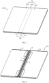
- FIG. 1 is a schematic diagram of a structure of an electronic device 1000 in an unfolded state according to an embodiment of this application.
- FIG. 2 is a schematic diagram of a structure of a folding apparatus 100 of the electronic device 1000 shown in FIG. 1 .
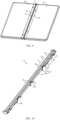
- FIG. 3 is a schematic diagram of a structure of the electronic device 1000 shown in FIG. 1 in an intermediate state.
- FIG. 4 is a schematic diagram of a structure of a folding apparatus 100 of the electronic device 1000 shown in FIG. 3 .
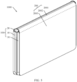
- FIG. 5 is a schematic diagram of a structure of the electronic device 1000 shown in FIG. 1 in a closed state.
- FIG. 6 is a schematic diagram of a structure of a folding apparatus 100 of the electronic device 1000 shown in FIG. 5 .
- the electronic device 1000 may be a product such as a mobile phone, a tablet computer, or a notebook computer. This embodiment is described by using an example in which the electronic device 1000 is a mobile phone.
- the electronic device 1000 includes a folding apparatus 100 and a flexible display 200.
- the folding apparatus 100 includes a first housing 10, a rotation mechanism 20, and a second housing 30 that are sequentially connected.
- the rotation mechanism 20 can deform, to enable the first housing 10 and the second housing 30 to be folded or unfolded relative to each other.
- the first housing 10 and the second housing 30 can be unfolded relative to each other to an unfolded state, so that the electronic device 1000 is in the unfolded state.
- an included angle between the first housing 10 and the second housing 30 may be substantially 180° (a slight deviation is allowed, for example, the included angle is 165°, 177°, or 185°).
- the first housing 10 and the second housing 30 can rotate (unfold or fold) relative to each other to an intermediate state, so that the electronic device 1000 is in the intermediate state.
- the first housing 10 and the second housing 30 can be folded relative to each other to a closed state, so that the electronic device 1000 is in the closed state.
- the first housing 10 and the second housing 30 can be totally closed to be parallel to each other (a slight deviation is allowed).
- the intermediate state shown in FIG. 3 and FIG. 4 may be any state between the unfolded state and the closed state. Therefore, the electronic device 1000 may switch between the unfolded state and the closed state through deformation of the rotation mechanism 20.
- the flexible display 200 is configured to display an image.
- the flexible display 200 may be an organic light-emitting diode (OLED) display, an active-matrix organic light-emitting diode (AMOLED) display, a mini light-emitting diode display, a micro light-emitting diode display, a micro organic light-emitting diode display, or a quantum dot light-emitting diode (QLED) display.
- OLED organic light-emitting diode
- AMOLED active-matrix organic light-emitting diode
- mini light-emitting diode display a micro light-emitting diode display
- a micro organic light-emitting diode display a micro organic light-emitting diode display
- QLED quantum dot light-emitting diode
- the flexible display 200 includes a first non-bending part 2001, a bending part 2002, and a second non-bending part 2003 that are sequentially arranged.
- the flexible display 200 is fastened to the folding apparatus 100.
- the flexible display 200 may be bonded to the folding apparatus 100 by using an adhesive layer.
- the first non-bending part 2001 of the flexible display 200 is fastened to the first housing 10, and the second non-bending part 2003 is fastened to the second housing 30.
- the bending part 2002 deforms.
- FIG. 1 when the first housing 10 and the second housing 30 are in an unfolded state, the flexible display 200 is in an unfolded form.
- FIG. 1 when the first housing 10 and the second housing 30 are in an unfolded state
- the flexible display 200 when the first housing 10 and the second housing 30 are in an intermediate state, the flexible display 200 is in an intermediate form between an unfolded form and a closed form. As shown in FIG. 5 , when the first housing 10 and the second housing 30 are in a closed state, the flexible display 200 is in a closed form. When the electronic device 1000 is in the closed state, the flexible display 200 is located on an outer side of the folding apparatus 100, and the flexible display 200 may be roughly in a U shape.
- the flexible display 200 can be unfolded or folded with the folding apparatus 100.
- the flexible display 200 is in the unfolded form, and can perform full-screen display, so that the electronic device 1000 has a large display area, to improve viewing experience of a user.
- a plane size of the electronic device 1000 is small (with a small width size), so that it is convenient for the user to carry and place the electronic device 1000.
- a rotation center of the electronic device 1000 is parallel to a width direction of the electronic device 1000" .
- the electronic device 1000 can rotate leftward and rightward, and folding and unfolding of the electronic device 1000 affect a width size of the electronic device 1000.
- a rotation center of the electronic device 1000 may alternatively be parallel to a length direction of the electronic device 1000. In this case, the electronic device 1000 can rotate up and down, and folding and unfolding of the electronic device 1000 affect a length size of the electronic device 1000.
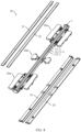
- FIG. 7 is a schematic exploded view of a partial structure of the folding apparatus 100 shown in FIG. 2 .
- FIG. 8 is a schematic exploded view of a partial structure of the rotation mechanism 20 shown in FIG. 7 .
- a fastener in the folding apparatus 100 is not shown in the accompanying drawings of this application, so as to simplify the drawings and show a main structure of the folding apparatus 100 more clearly.
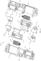
- the rotation mechanism 20 of the folding apparatus 100 includes a main shaft assembly 1, end connection components 20a, a synchronous connection component 20b, a first support plate 21, a second support plate 22, a first shielding plate 23, and a second shielding plate 24.
- the main shaft assembly 1 is located between the first housing 10 and the second housing 30.
- the end connection components 20a are connected to the first housing 10, the main shaft assembly 1, and the second housing 30.
- There are two end connection components 20a, and the two end connection components 20a are arranged at intervals in an axial direction of the main shaft assembly 1, for example, may be respectively connected to a top and a bottom of the main shaft assembly 1.
- the synchronous connection component 20b is connected to the first housing 10, the main shaft assembly 1, and the second housing 30.
- the synchronous connection component 20b is located between the two end connection components 20a.
- the first support plate 21 and the second support plate 22 are located on one side of the plurality of connection components (that is, the two end connection components 20a and the synchronous connection component 20b), and the first shielding plate 23 and the second shielding plate 24 are located on the other side of the plurality of connection components (20a and 20b).
- the first support plate 21 is located on a side that is of the main shaft assembly 1 and that faces the first housing 10, and the first support plate 21 connects the two end connection components 20a.
- the second support plate 22 is located on a side that is of the main shaft assembly 1 and that faces the second housing 30, and the second support plate 22 connects the two end connection components 20a.
- the main shaft assembly 1 has a support surface 11, and the support surface 11 of the main shaft assembly 1 is partially exposed relative to the first support plate 21 and the second support plate 22.
- the support surface 11 of the main shaft assembly 1 is configured to support the flexible display 200.
- the first support plate 21 and the second support plate 22 move along with the end connection components 20a, so that when the first housing 10 and the second housing 30 are in an unfolded state, an intermediate state, and a closed state, the first support plate 21 and the second support plate 22 can provide strong support for the bending part 2002 of the flexible display 200 together with the main shaft assembly 1. In this way, the flexible display 200 is not easily damaged due to touching by an external force, reliability of the flexible display 200 is improved, and a service life of the flexible display 200 is long.
- the support surface 11 of the main shaft assembly 1 includes a first arc surface region 111, a plane region 112, and a second arc surface region 113 that are sequentially arranged in a direction from the first support plate 21 to the second support plate 22.
- the direction from the first support plate 21 to the second support plate 22 is perpendicular to an extension direction of the main shaft assembly 1.
- the first arc surface region 111 is located between the first support plate 21 and the plane region 112
- the second arc surface region 113 is located between the plane region 112 and the second support plate 22.
- the plane region 112 of the support surface 11 of the main shaft assembly 1 can provide flat strong support for the flexible display 200 when the folding apparatus 100 is in the unfolded state, to improve press touch experience of the flexible display 200.
- the first arc surface region 111 and the second arc surface region 113 of the support surface 11 of the main shaft assembly 1 can respectively form a smooth transition with the first support plate 21 and the second support plate 22 when the folding apparatus 100 is in the intermediate state and the closed state. In this way, the main shaft assembly 1, the first support plate 21, and the second support plate 22 can jointly provide a smooth support surface for the bending part 2002 of the flexible display 200. Therefore, the rotation mechanism 20 has a good support effect for the flexible display 200.
- the support surface 11 of the main shaft assembly 1 may alternatively have another shape.
- the support surface 11 of the main shaft assembly 1 is in an arc shape.
- the support surface 11 of the main shaft assembly 1 is disposed in a semi-ellipse shape, so as to reduce a width of the folding apparatus 100 in the closed state. In this way, the folding apparatus 100 is easy to carry and place.
- a shape of the support surface 11 of the main shaft assembly 1 is not strictly limited in this embodiment of this application.
- the first housing 10 has a first support surface 101, and the first support surface 101 is configured to support the flexible display 200.
- the second housing 30 has a second support surface 301, and the second support surface 301 is configured to support the flexible display 200.
- the first support surface 101 is flush with the second support surface 301, to well support the flexible display 200. In this way, the flexible display 200 is more flat, thereby improving user experience.
- the two end connection components 20a may be of a mirror symmetric structure, and the symmetry mirror is perpendicular to a circumferential direction of the main shaft assembly 1.
- the rotation mechanism 20 has a simple overall structure and low processing costs.
- stress between the two end connection components 20a and the main shaft assembly 1, the first housing 10, and the second housing 30 is uniform. This helps improve reliability of the folding apparatus 100.
- a structure of one end connection component 20a is mainly used for description.
- structures of the two end connection components may alternatively be different. It may be understood that a structure of the rotation mechanism 20 may have a plurality of combination and deformation manners. This is not strictly limited in this embodiment of this application.
- FIG. 9 is a schematic diagram of a structure of the folding apparatus 100 shown in FIG. 2 from another angle.
- a field of view of the folding apparatus 100 in FIG. 9 is a field of view obtained after the field of view in FIG. 2 is flipped.
- the first shielding plate 23 is located on a side that is of the main shaft assembly 1 and that faces the first housing 10, and the first shielding plate 23 connects the two end connection components 20a.
- the second shielding plate 24 is located on a side that is of the main shaft assembly 1 and that faces the second housing 30, and the second shielding plate 24 connects the two end connection components 20a.
- the main shaft assembly 1 has a shielding surface 12.
- the first shielding plate 23 is located between the first housing 10 and the main shaft assembly 1, and can shield a gap between the first housing 10 and the main shaft assembly 1.
- the second shielding plate 24 is located between the second housing 30 and the main shaft assembly 1, and can shield a gap between the second housing 30 and the main shaft assembly 1. Therefore, the rotation mechanism 20 can shield, in the unfolded state, a gap between the first housing 10 and the second housing 30 by using the first shielding plate 23, the main shaft assembly 1, and the second shielding plate 24 together. This implements self-shielding, improves appearance integrity, and reduces a risk of external dust and foreign matters entering the rotation mechanism 20, to ensure reliability of the folding apparatus 100.
- FIG. 10 is a partial schematic exploded view of a partial structure of the folding apparatus 100 shown in FIG. 2 .
- FIG. 11 is a schematic exploded view of a structure of the main shaft assembly 1 shown in FIG. 10 .
- FIG. 12 is a schematic diagram of a structure of the main outer shaft 14 shown in FIG. 11 from another angle.
- the main shaft assembly 1 includes a main outer shaft 14, a main inner shaft 15, and a shielding plate 16.
- the main outer shaft 14 is fastened to one side of the main inner shaft 15, and the shielding plate 16 is fastened to the other side of the main inner shaft 15.
- the support surface 11 of the main shaft assembly 1 is formed on the main outer shaft 14, and is disposed away from the main inner shaft 15.
- the shielding surface 12 of the main shaft assembly 1 is formed on the shielding plate 16, and is disposed away from the main outer shaft 14.
- the main inner shaft 15 may include a plurality of portions, and the plurality of portions are respectively fastened to the main outer shaft 14.
- the main inner shaft 15 may alternatively be an integrally formed structure.
- the shielding plate 16 may be mutually fastened to the main inner shaft 15 in an assembly manner.
- the shielding plate 16 and the main inner shaft 15 may alternatively be integrally formed mechanical parts.
- a plurality of three-dimensional space structures are disposed on both the main inner shaft 15 and the main outer shaft 14. These structures are designed, so that after the main inner shaft 15 and the main outer shaft 14 are assembled, a plurality of movement spaces can be formed together, and mechanical parts of the plurality of connection components (20a and 20b) are movably disposed in the plurality of movement spaces of the main shaft assembly 1. This implements a connection to the main shaft assembly 1.
- the main inner shaft 15 and the main outer shaft 14 are separately designed. This helps reduce a difficulty of making the main shaft assembly 1, and improve precision of making the main shaft assembly 1 and a product yield rate.
- a rotation center of the rotation mechanism 20 is integrally parallel to an axial direction of the main shaft assembly 1, and the main shaft assembly 1 extends in the axial direction thereof.
- the main inner shaft 15 includes a first portion 15a, a second portion 15b, and a third portion 15c.
- the third portion 15c and the first portion 15a may be of a mirror symmetric structure, and the second portion 15b is located between the third portion 15c and the first portion 15a.
- the first portion 15a of the main inner shaft 15 includes a body 151 and a plurality of grooves 152, a plurality of bumps 153, and a plurality of fastening holes 154 that are formed on the body 151.
- the plurality of grooves 152 and the plurality of bumps 153 are mutually combined to form a plurality of three-dimensional space structures.
- the second portion 15b of the main inner shaft 15 includes a body 155 and two grooves 156, two bumps 157, and two fastening holes 158 that are formed on the body 155.
- the two grooves 156 and the two bumps 157 are mutually combined to form a three-dimensional space structure.
- reference numerals of some grooves 152, some bumps 153, some fastening holes 154, some grooves 156, some bumps 157, and some fastening holes 158 are schematically marked.
- the main outer shaft 14 includes a main outer shaft body 141, two end stoppers, a plurality of grooves 143, a plurality of bumps 144, and a plurality of fastening holes 145.
- the two end stoppers are respectively fastened at two ends of the main outer shaft body 141.
- the plurality of bumps 144 are formed on the main outer shaft body 141, and the plurality of grooves 143 and the plurality of fastening holes 145 are formed on the main outer shaft body 141 and/or the bumps 144.
- the plurality of grooves 143 and the plurality of bumps 144 are mutually combined to form a plurality of three-dimensional space structures. Reference numerals of some grooves 143, some bumps 144, and some fastening holes 145 are schematically marked in FIG. 12 .
- the main outer shaft body 141 and the main inner shaft body 151 are in contact with each other, the end stopper 142 of the main outer shaft 14 is exposed, and the plurality of fastening holes 145 of the main outer shaft 14 are aligned with the plurality of fastening holes (154, 158) of the main inner shaft 15.
- the main inner shaft 15 and the main outer shaft 14 are fastened by using a fastener (not shown in the figure).
- the fastener includes but is not limited to a screw, a bolt, a rivet, a pin, and the like.
- the plurality of three-dimensional space structures of the main outer shaft 14 and the plurality of three-dimensional space structures of the main inner shaft 15 jointly form a plurality of movement spaces of the main shaft assembly 1.
- some of the plurality of movement spaces are the same in structure, and some of the plurality of movement spaces are different in structure.
- Movement spaces with different structures are used to cooperate with mechanical parts with different structures, so that a connection structure between the main shaft assembly 1 and the plurality of connection components (20a and 20b) is more flexible and diversified.
- the movement space having a same structure is used to cooperate with the mechanical part having a same structure. This helps reduce design difficulty and costs of the main shaft assembly 1 and the connection component.
- limiting grooves 1431 are disposed on groove walls of some grooves 143 of the main outer shaft 14, to limit, in an axial direction of the main shaft assembly 1, a mechanical part disposed in a corresponding movement space, so as to improve reliability of a connection structure.
- some bumps 144 of the main outer shaft 14 have a limiting function. These bumps 144 are located in the movement space of the main shaft assembly 1, and are configured to limit the mechanical part of the connection component, so as to prevent the mechanical part from accidentally detaching from the main shaft assembly 1. This improves reliability of connection and movement between the connection component and the main shaft assembly 1, so that reliability of the rotation mechanism 20 and the folding apparatus 100 is high. It may be understood that, the main shaft assembly 1 may also be provided with a bump for positioning or limiting on the main inner shaft 15.
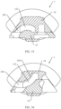
- FIG. 13 is a schematic diagram of a structure of the main shaft assembly 1 shown in FIG. 10 that is cut along a line A-A.
- FIG. 14 is a schematic diagram of a structure of the main shaft assembly 1 shown in FIG. 10 that is cut along a line B-B.
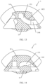
- FIG. 15 is a schematic diagram of a structure of the main shaft assembly 1 shown in FIG. 10 that is cut along a line C-C.
- FIG. 16 is a schematic diagram of a structure of the main shaft assembly 1 shown in FIG. 10 that is cut along a D-D line.
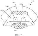
- FIG. 17 is a schematic diagram of a structure of the main shaft assembly 1 shown in FIG. 10 that is cut along a line E-E.
- the main shaft assembly 1 forms a plurality of movement spaces, and the plurality of movement spaces are used to cooperate with different mechanical parts of the connection component.
- the main outer shaft 14 and the main inner shaft 15 jointly enclose an arc groove 131.
- a circle center of the arc groove 131 is close to the main outer shaft 14 and away from the main inner shaft 15, to form a movement space.
- the movement space may further include a limiting groove 1431 connected to the arc groove 131, and the limiting groove 1431 is formed on the main outer shaft 14.
- the main outer shaft 14 may further include a bump 144 having a limiting function, and the bump 144 extends into the arc groove 131, to limit the mechanical part disposed in the movement space.
- the main outer shaft 14 and the main inner shaft 15 jointly enclose an arc groove 131.
- a circle center of the arc groove 131 is close to the main inner shaft 15 and away from the main outer shaft 14, to form a movement space.
- the main outer shaft 14 may further include a bump 144 having a limiting function, and the bump 144 extends into the arc groove 131, to limit the mechanical part disposed in the movement space.
- the main outer shaft 14 and the main inner shaft 15 jointly enclose an arc groove 131.
- a circle center of the arc groove 131 is close to the main inner shaft 15 and away from the main outer shaft 14, to form a movement space.
- the main outer shaft 14 may further include a bump 144 having a limiting function, and the bump 144 extends into the arc groove 131, to limit the mechanical part disposed in the movement space.
- the movement space shown in FIG. 15 and the movement space shown in FIG. 14 are disposed in pairs.
- the main outer shaft 14 and the main inner shaft 15 jointly enclose an arc groove 131.
- a circle center of the arc groove 131 is close to the main outer shaft 14 and away from the main inner shaft 15, to form a movement space.
- the movement space may further include a limiting groove 1431 connected to the arc groove 131, and the limiting groove 1431 is formed on the main outer shaft 14.
- the main outer shaft 14 may further include a bump 144 having a limiting function, and the bump 144 extends into the arc groove 131, to limit the mechanical part disposed in the movement space.
- the movement space shown in FIG. 16 and the movement space shown in FIG. 13 are disposed in pairs.
- the main outer shaft 14 and the main inner shaft 15 jointly enclose an M-shaped groove 132.
- Two concave grooves 133 disposed at intervals are formed on a side wall of the M-shaped groove 132, and the M-shaped groove 132 and the two concave grooves 133 jointly form a movement space.
- main shaft assembly 1 in this embodiment of this application may alternatively have another structure. This is not strictly limited in this application.
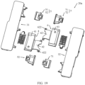
- FIG. 18 is a schematic diagram of a structure of the end connection component 20a shown in FIG. 10 from another angle.
- FIG. 19 is a schematic exploded view of a partial structure of the end connection component 20a shown in FIG. 18 .
- FIG. 20 is a schematic diagram of a structure of the end connection component 20a shown in FIG. 10 from still another angle.
- FIG. 21 is a schematic exploded view of a partial structure of the end connection component 20a shown in FIG. 20 .
- a field of view shown in FIG. 20 is flipped relative to a field of view shown in FIG. 18 .
- the end connection component 20a of the rotation mechanism 20 includes a first fastening bracket 31, a first transmission arm 4, a first rotation arm 5, a second fastening bracket 32, a second transmission arm 6, and a second rotation arm 7.
- the first rotation arm 5 includes a first rotation part 51 and a second rotation part 52, and the second rotation part 52 and the first rotation part 51 are two mechanical parts independent of each other.
- the second rotation arm 7 includes a third rotation part 71 and a fourth rotation part 72, and the fourth rotation part 72 and the third rotation part 71 are two mechanical parts independent of each other.
- the first fastening bracket 31 is fastened to the first housing 10.
- the first transmission arm 4 includes a sliding end 41 and a rotation end 42.
- the sliding end 41 of the first transmission arm 4 is slidably connected to the first fastening bracket 31, and the rotation end 42 of the first transmission arm 4 is rotatably connected to the main shaft assembly 1.
- the first rotation arm 5 is rotatably connected to the first fastening bracket 31 by using the first rotation part 51, and is rotatably connected to the main shaft assembly 1 by using the second rotation part 52. That is, one end of the first rotation arm 5 is rotatably connected to the first fastening bracket 31, and the other end is rotatably connected to the main shaft assembly 1.
- the second fastening bracket 32 is fastened to the second housing 30.
- the second transmission arm 6 includes a sliding end 61 and a rotation end 62, the sliding end 61 of the second transmission arm 6 is slidably connected to the second fastening bracket 32, and the rotation end 62 of the second transmission arm 6 is rotatably connected to the main shaft assembly 1.
- the second rotation arm 7 is rotatably connected to the second fastening bracket 31 by using the third rotation part 71, and is rotatably connected to the main shaft assembly 1 by using the fourth rotation part 72.
- One end of the second rotation arm 7 is rotatably connected to the second fastening bracket 32, and the other end is rotatably connected to the main shaft assembly 1.
- FIG. 22 is a schematic diagram of an exploded structure of a first fastening bracket 31 of the end connection component 20a shown in FIG. 21 .
- the first fastening bracket 31 includes a first fastening base 311 and a first snapping part 312.
- the first snapping part 312 is fastened to the first fastening base 311, and the first snapping part 312 and the first fastening base 311 jointly enclose a first arc groove 313.
- the first snapping part 312 may be mutually fastened to the first fastening base 311 by using a fastener.
- a processing manner in which the first fastening base 311 and the first snapping part 312 are separately manufactured, and then the first fastening base 311 and the first snapping part 312 are assembled into the first fastening bracket 31 helps reduce a processing difficulty of the first fastening bracket 31, and improve a product yield rate of the first fastening bracket 31.
- the first fastening bracket 31 may alternatively be an integrally formed structure.
- the first fastening base 311 of the first fastening bracket 31 may further have a first sliding slot 314.
- a side wall of the first sliding slot 314 may have concave guide space 3141.
- the first fastening base 311 may further have a first concave region 315 and a second concave region 316, and both the first concave region 315 and the second concave region 316 communicate with the first sliding slot 314.
- the first concave region 315 is located on a side that is of the second concave region 316 and that is close to the second fastening bracket 32. Refer to FIG. 8 , the first concave region 315 is located between the main shaft assembly 1 and the second concave region 316.
- the first fastening base 311 of the first fastening bracket 31 has a plurality of fastening holes 3111.
- the rotation mechanism 20 may fasten the first fastening bracket 31 to the first housing 10 by using a plurality of fasteners.
- the first snapping part 312 has a fastening hole 3121, configured to align with some fastening holes 3111 of the first fastening base 311, so as to mutually lock and fasten the first snapping part 312 and the first fastening base 311 by using a fastener.
- FIG. 23 is a schematic diagram of an exploded structure of a second fastening bracket 32 of the end connection component 20a shown in FIG. 21 .
- the second fastening bracket 32 includes a second fastening base 321 and a second snapping part 322.
- the second snapping part 322 is fastened to the second fastening base 321, and the second snapping part 322 and the second fastening base 321 jointly enclose a second arc groove 323.
- the second fastening base 321 of the second fastening bracket 32 may further have a second sliding slot 324.
- a side wall of the second sliding slot 324 may have concave guide space 3241.
- the second fastening base 321 may further have a third concave region 325 and a fourth concave region 326, and both the third concave region 325 and the fourth concave region 326 communicate with the second sliding slot 324.
- the third concave region 325 is located on a side that is of the fourth concave region 326 and that is close to the first fastening bracket 31. Refer to FIG. 8 , the third concave region 325 is located between the main shaft assembly 1 and the fourth concave region 326.
- the rotation end 42 of the first transmission arm 4 is in an arc shape.
- the rotation end 42 of the first transmission arm 4 may be disposed in one arc groove 131 of the main shaft assembly 1, so that the first transmission arm 4 is rotatably connected to the main shaft assembly 1.
- a rotation center in which the first transmission arm 4 rotates relative to the main shaft assembly 1 is close to the main inner shaft 15 and is away from the main outer shaft 14.
- the first transmission arm 4 is connected to the main shaft assembly 1 by using a virtual shaft.
- a rotatable connection structure is simple, and occupies small space.
- the first transmission arm 4 and the main shaft assembly 1 may alternatively be connected by using a real shaft. This is not strictly limited in this embodiment of this application.
- the rotation end 42 of the first transmission arm 4 may include a limiting bump 422, and the limiting bump 422 is formed at an end position of the rotation end 42.
- the limiting bump 422 is configured to cooperate with a bump 144 having a limiting function of the main shaft assembly 1, to prevent the first transmission arm 4 from accidentally detaching from the main shaft assembly 1.
- the sliding end 41 of the first transmission arm 4 includes a first flange 413 located on a peripheral side.
- the sliding end 41 of the first transmission arm 4 is disposed in the first sliding slot 314 of the first fastening bracket 31, and the first flange 413 is disposed in the guide space 3141 of the first sliding slot 314.
- the guide space 3141 of the first sliding slot 314 cooperates with the first flange 413 of the first transmission arm 4, so that the sliding end 41 of the first transmission arm 4 can be guided in a sliding direction of the first sliding slot 314. In this way, a relative sliding action between the first transmission arm 4 and the first fastening bracket 31 is easy to implement with high control precision.
- the rotation mechanism 20 further includes a first stopper 81, and the first stopper 81 is disposed on the sliding end 41 of the first transmission arm 4.
- the first stopper 81 is clamped into the first fastening bracket 31.
- a relative position relationship between the first transmission arm 4 and the first fastening bracket 31 can be limited, so that the first transmission arm 4 and the first fastening bracket 31 can maintain a preset relative position relationship without a large external force, the rotation mechanism 20 can stay at a preset angle, and a rotation mechanism can maintain an unfolded state or a closed state.
- the first stopper 81 when the first housing 10 and the second housing 30 are unfolded relative to each other to an unfolded state, the first stopper 81 is partially clamped into the first concave region 315. When the first housing 10 and the second housing 30 are folded relative to each other to a closed state, the first stopper 81 is partially clamped into the second concave region 316.
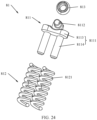
- FIG. 24 is a schematic diagram of an exploded structure of a first stopper 81 of the end connection component 20a shown in FIG. 21 .
- the first stopper 81 includes a first bracket 811 and a first elastic part 812.
- the first bracket 811 is of a rigid structure, and is not prone to deformation under an external force.
- the first bracket 811 includes a control portion 8111 and an abutment portion 8112.
- the abutment portion 8112 is configured to abut against an external mechanical part, to limit the mechanical part.
- the control portion 8111 is configured to control a position of the abutment portion 8112.
- the control portion 8111 includes a substrate 8113 and a plurality of guide posts 8114, and the plurality of guide posts 8114 are fastened to one side of the substrate 8113 at intervals.
- the abutment portion 8112 is fastened to the other side of the substrate 8113.
- the first elastic part 812 is of an elastic structure, and is prone to deformation under an external force.
- One end of the first elastic part 812 is disposed on the control portion 8111 of the first bracket 811.
- the first elastic part 812 may include a plurality of springs 8121, and the plurality of springs 8121 sleeve the plurality of guide posts 8114 in a one-to-one correspondence.
- the sliding end 41 of the first transmission arm 4 has a first accommodating groove 411, and the first stopper 81 is disposed in the first accommodating groove 411.
- the other end (that is, an end away from the control portion 8111) of the first elastic part 812 abuts against a groove wall of the first accommodating groove 411, the first elastic part 812 is in a compressed state, and the abutment portion 8112 of the first bracket 811 is clamped into the first fastening bracket 31.
- the first elastic part 812 of the first stopper 81 can deform under an external force, so that the first stopper 81 can smoothly move between the first concave region 315 and the second concave region 316 relative to the first fastening bracket 31. This improves limiting reliability between the first stopper 81 and the sliding end 41 of the first transmission arm 4.
- the first stopper 81 may further include a first buffer part 813, and the first buffer part 813 is disposed on the abutment portion 8112 of the first bracket 811.
- the first buffer part 813 may be made of a material (for example, rubber) with small stiffness, so that when being subjected to an external force, the first buffer part 813 can absorb an impact force through deformation, thereby implementing buffering.
- the first stopper 81 can buffer stress between the abutment portion 8112 and the mechanical part by disposing the first buffer part 813. Therefore, reliability of a limiting structure is improved.
- the first stopper 81 abuts against the first fastening bracket 31 by using the first buffer part 813 having a buffer function. This helps reduce a risk of wear between the first bracket 811 and the first fastening bracket 31 in a long-time relative movement process, improve limiting reliability of the first stopper 81, and improve reliability of the rotation mechanism 20.
- the rotation end 62 of the second transmission arm 6 is in an arc shape.
- the rotation end 62 of the second transmission arm 6 may be disposed in one arc groove 131 of the main shaft assembly 1, so that the second transmission arm 6 is rotatably connected to the main shaft assembly 1.
- a rotation center in which the second transmission arm 6 rotates relative to the main shaft assembly 1 is close to the main inner shaft 15 and is away from the main outer shaft 14.
- the second transmission arm 6 is connected to the main shaft assembly 1 by using a virtual shaft.
- a rotatable connection structure is simple, and occupies small space.
- the second transmission arm 6 and the main shaft assembly 1 may alternatively be connected by using a real shaft. This is not strictly limited in this embodiment of this application.
- the rotation end 62 of the second transmission arm 6 may include a limiting bump 622, and the limiting bump 622 is formed at an end position of the rotation end 62.
- the limiting bump 622 is configured to cooperate with a bump having a limiting function of the main shaft assembly 1, to prevent the second transmission arm 6 from accidentally detaching from the main shaft assembly 1.
- the sliding end 61 of the second transmission arm 6 includes a second flange 613 located on a peripheral side.
- the sliding end 61 of the second transmission arm 6 is disposed in the second sliding slot 324 of the second fastening bracket 32, and the second flange 613 is disposed in the guide space 3241 of the second sliding slot 324.
- the guide space 3241 of the second sliding slot 324 cooperates with the second flange 613 of the second transmission arm 6, so that the sliding end 61 of the second transmission arm 6 can be guided in a sliding direction of the first sliding slot 314. In this way, a relative sliding action between the first transmission arm 4 and the first fastening bracket 31 is easy to implement, and high in control precision.
- the rotation mechanism 20 further includes a second stopper 82, and the second stopper 82 is disposed on the sliding end 61 of the second transmission arm 6.
- the second stopper 82 is clamped into the second fastening bracket 32.
- a relative position relationship between the second transmission arm 6 and the second fastening bracket 32 can be limited, so that the second transmission arm 6 and the second fastening bracket 32 can maintain a preset relative position relationship without a large external force.
- the rotation mechanism 20 can stay at a preset angle, and a rotation mechanism can maintain an unfolded state or a closed state, to improve user experience of the folding apparatus 100 and the electronic device 1000.
- a rotation mechanism can maintain an unfolded state or a closed state, to improve user experience of the folding apparatus 100 and the electronic device 1000.
- the second stopper 82 when the first housing 10 and the second housing 30 are unfolded relative to each other to an unfolded state, the second stopper 82 is partially clamped into the third concave region 325.
- the second stopper 82 is partially clamped into the fourth concave region 326.
- a structure of the second stopper 82 may be the same as a structure of the first stopper 81, to simplify material types of the rotation mechanism 20, and reduce design difficulty and costs of the rotation mechanism 20.
- a structure of the second stopper 82 is not described in detail in this embodiment of this application.
- FIG. 25 is a schematic diagram of a partial structure of the rotation mechanism 20 shown in FIG. 7 .
- FIG. 26 is a schematic diagram of a structure of the first support plate 21 shown in FIG. 25.
- FIG. 25 shows structures of the first support plate 21, the first rotation part 51, and the second rotation part 52 of the rotation mechanism 20.
- the first rotation part 51 of the first rotation arm 5 includes a fixed portion 511 and a rotation portion 512.
- the rotation portion 512 of the first rotation part 51 is fastened to the fixed portion 511 of the first rotation part 51, and the first rotation part 51 may be an integrally formed mechanical part.
- the second rotation part 52 of the first rotation arm 5 includes a fixed portion 521 and a rotation portion 522.
- the rotation portion 522 of the second rotation part 52 is fastened to the fixed portion 521 of the second rotation part 52, and the second rotation part 52 may be an integrally formed mechanical part.
- the fixed portion 511 of the first rotation part 51 is fastened to the first support plate 21.
- the fixed portion 521 of the second rotation part 52 is fastened to the first support plate 21.
- the rotation portion 512 of the first rotation part 51 and the rotation portion 522 of the second rotation part 52 respectively extend towards two sides of the first support plate 21. In other words, the first support plate 21 is fixedly connected to the first rotation arm 5.
- the first support plate 21 includes a plate body 211 and a first fastening block 212, a first positioning block 213, a second fastening block 214, and a second positioning block 215 that are fastened to the plate body 211.
- the first support plate 21 may be an integrally formed mechanical part.
- the fixed portion 511 of the first rotation part 51 is fastened to the first fastening block 212, and abuts against the first positioning block 213.
- the fixed portion 521 of the second rotation part 52 is fastened to the second fastening block 214, and abuts against the second positioning block 215.
- the fixed portion 511 of the first rotation part 51 may sleeve on the outside of the first fastening block 212, and fastening holes are disposed in both the fixed portion 511 and the first fastening block 212, so as to mutually lock and fasten the fixed portion 511 and the first fastening block 212 by using a fastener.
- the fixed portion 521 of the second rotation part 52 may sleeve on the outside of the second fastening block 214, and fastening holes are disposed in both the fixed portion 521 and the second fastening block 214, so as to mutually lock and fasten the fixed portion 521 and the second fastening block 214 by using a fastener.
- the fixed portion 511 of the first rotation part 51 and the fixed portion 521 of the second rotation part 52 may also be fastened to the first support plate 21 by bonding or the like.
- the second rotation part 52 and the first rotation part 51 are fastened to each other, and the second rotation part 52 and the first rotation part 51 are equivalent to a mechanical part that can transmit force and movement.
- An end that is of the first rotation arm 5 and that is rotatably connected to the first fastening bracket 31 is formed on the rotation portion 512 of the first rotation part 51, and the rotation portion 512 of the first rotation part 51 is rotatably connected to the first fastening bracket 31.
- the rotation portion 512 of the first rotation part 51 is in an arc shape, and the rotation portion 512 of the first rotation part 51 is disposed in the first arc groove 313 of the first fastening bracket 31.
- the end that is of the first rotation arm 5 and that is rotatably connected to the first fastening bracket 31 is in an arc shape and is disposed in the first arc groove 313.
- the first rotation arm 5 is connected to the first fastening bracket 31 by using a virtual shaft.
- a rotatable connection structure is simple, and occupies small space. This helps reduce a thickness of the rotation mechanism 20, so that the folding apparatus 100 and the electronic device 1000 are lighter and thinner.
- the first rotation arm 5 and the first fastening bracket 31 may alternatively be connected by using a real shaft. This is not strictly limited in this embodiment of this application.
- An end that is of the first rotation arm 5 and that is rotatably connected to the main shaft assembly 1 is formed on the rotation portion 522 of the second rotation part 52, and the rotation portion 522 of the second rotation part 52 is rotatably connected to the main shaft assembly 1.
- the rotation portion 522 of the second rotation part 52 is in an arc shape, and the rotation portion 522 of the second rotation part 52 can be disposed in the movement space of the main shaft assembly 1 (as shown in FIG. 16 ), so as to be rotatably connected to the main shaft assembly 1.
- the end that is of the first rotation arm 5 and that is rotatably connected to the main shaft assembly 1 is in an arc shape and is disposed in one arc groove 131 of the main shaft assembly 1.
- a rotation center in which the first rotation arm 5 rotates relative to the main shaft assembly 1 is close to the main outer shaft 14 and away from the main inner shaft 15.
- the first rotation arm 5 is connected to the main shaft assembly 1 by using a virtual shaft.
- a rotatable connection structure is simple, and occupies small space. This helps reduce a thickness of the rotation mechanism 20, so that the folding apparatus 100 and the electronic device 1000 are lighter and thinner.
- the first rotation arm 5 and the main shaft assembly 1 may alternatively be connected by using a real shaft. This is not strictly limited in this embodiment of this application.
- the first rotation arm 5 including the first rotation part 51 and the second rotation part 52 can transfer force and movement between the main shaft assembly 1 and the first fastening bracket 31.
- the first transmission arm 4 is also configured to transfer force and movement between the main shaft assembly 1 and the first fastening bracket 31, the rotation mechanism 20 controls relative movement between the first fastening bracket 31 and the main shaft assembly 1 by using both the first transmission arm 4 and the first rotation arm 5.
- FIG. 27 is a schematic diagram of another partial structure of the rotation mechanism 20 shown in FIG. 7 .
- FIG. 27 shows structures of the second support plate 22, the third rotation part 71, and the fourth rotation part 72 of the rotation mechanism 20.
- the third rotation part 71 of the second rotation arm 7 includes a fixed portion 711 and a rotation portion 712.
- the rotation portion 712 of the third rotation part 71 is fastened to the fixed portion 711 of the third rotation part 71, and the third rotation part 71 may be an integrally formed mechanical part.
- the fourth rotation part 72 of the second rotation arm 7 includes a fixed portion 721 and a rotation portion 722.
- the rotation portion 722 of the fourth rotation part 72 is fastened to the fixed portion 721 of the fourth rotation part 72, and the fourth rotation part 72 may be an integrally formed mechanical part.
- the fixed portion 711 of the third rotation part 71 is fastened to the second support plate 22.
- the fixed portion 721 of the fourth rotation part 72 is fastened to the second support plate 22.
- the rotation portion 712 of the third rotation part 71 and the rotation portion 722 of the fourth rotation part 72 respectively extend to two sides of the second support plate 22.
- the second support plate 22 is fixedly connected to the second rotation arm 7.
- a structure of the second support plate 22 may be similar to a structure of the first support plate 21.
- a fastening structure of the third rotation part 71 and the fourth rotation part 72 to the second support plate 22 may also be similar to a fastening structure of the first rotation part 51 and the second rotation part 52 to the first support plate 21. Details are not described in this embodiment of this application.
- the fourth rotation part 72 and the third rotation part 71 are fastened to each other, and the fourth rotation part 72 and the third rotation part 71 are jointly equivalent to a mechanical part that can transfer force and movement.
- An end that is of the second rotation arm 7 and that is rotatably connected to the second fastening bracket 32 is formed on the rotation portion 712 of the third rotation part 71, and the rotation portion 712 of the third rotation part 71 is rotatably connected to the second fastening bracket 32.
- the rotation portion 712 of the third rotation part 71 is in an arc shape, and the rotation portion 712 of the third rotation part 71 is disposed in the second arc groove 323 of the second fastening bracket 32.
- the end that is of the second rotation arm 7 and that is rotatably connected to the second fastening bracket 32 is in an arc shape and is disposed in the second arc groove 323.
- the second rotation arm 7 is connected to the second fastening bracket 32 by using a virtual shaft.
- a rotatable connection structure is simple, and occupies small space. This helps reduce a thickness of the rotation mechanism 20, so that the folding apparatus 100 and the electronic device 1000 are lighter and thinner.
- the second rotation arm 7 and the second fastening bracket 32 may alternatively be connected by using a real shaft. This is not strictly limited in this embodiment of this application.
- An end that is of the second rotation arm 7 and that is rotatably connected to the main shaft assembly 1 is formed on the rotation portion 722 of the fourth rotation part 72, and the rotation portion 722 of the fourth rotation part 72 is rotatably connected to the main shaft assembly 1.
- the rotation portion 722 of the fourth rotation part 72 is in an arc shape, and the rotation portion 722 of the fourth rotation part 72 can be disposed in the movement space of the main shaft assembly 1 (as shown in FIG. 13 ), so as to be rotatably connected to the main shaft assembly 1.
- the end that is of the second rotation arm 7 and that is rotatably connected to the main shaft assembly 1 is in an arc shape and is disposed in one arc groove 131 of the main shaft assembly 1.
- a rotation center in which the second rotation arm 7 rotates relative to the main shaft assembly 1 is close to the main outer shaft 14 and away from the main inner shaft 15.
- the second rotation arm 7 is connected to the main shaft assembly 1 by using a virtual shaft.
- a rotatable connection structure is simple, and occupies small space. This helps reduce a thickness of the rotation mechanism 20, so that the folding apparatus 100 and the electronic device 1000 are lighter and thinner.
- the second rotation arm 7 and the main shaft assembly 1 may alternatively be connected by using a real shaft. This is not strictly limited in this embodiment of this application.
- the second rotation arm 7 including the third rotation part 71 and the fourth rotation part 72 can transfer force and movement between the main shaft assembly 1 and the second fastening bracket 32.
- the rotation mechanism 20 controls relative movement between the second fastening bracket 32 and the main shaft assembly 1 by using both the second transmission arm 6 and the second rotation arm 7.
- the first rotation arm 5 can directly control a movement track of the first support plate 21, and the second rotation arm 7 can directly control a movement track of the second support plate 22.
- a movement process of the first support plate 21 and the second support plate 22 is high in control precision with a small hysteresis error, and therefore, the rotation mechanism 20 can meet a support requirement of the flexible display 200.
- first rotation arm 5 and the second rotation arm 7 may have another implementation.
- FIG. 28 is a schematic diagram of a structure of the first rotation arm 5 shown in FIG. 21 in some other embodiments.
- the first rotation arm 5 may further include a first fastening part 53. That is, the first rotation arm 5 includes the first rotation part 51, the second rotation part 52, and the first fastening part 53.
- the fixed portion 511 of the first rotation part 51 is fastened to the first fastening part 53
- the fixed portion 521 of the second rotation part 52 is fastened to the first fastening part 53.
- a fastening structure of the fixed portion 511 of the first rotation part 51 to the first fastening part 53 refer to the fastening structure of the fixed portion 511 of the first rotation part 51 to the first support plate 21.
- the first fastening part 53 is fixedly connected to the first support plate 21.
- the first fastening part 53 and the first support plate 21 may be fastened in a manner of bonding, fastener connection, or the like.
- a plurality of mechanical parts of the first rotation arm 5 may be first assembled to form a modular structure, and then assembled with the first support plate 21. This helps improve assembly precision.
- first fastening bracket 31 and the main shaft assembly 1 that cooperate with the first fastening part 53 refer to the foregoing embodiments.
- the second rotation arm 7 further includes a second fastening part. That is, the second rotation arm 7 includes the third rotation part 71, the fourth rotation part 72, and the second fastening part.
- the fixed portion 711 of the third rotation part 71 is fixedly connected to the second fastening part
- the fixed portion 721 of the fourth rotation part 72 is fixedly connected to the second fastening part
- the second fastening part is fixedly connected to the second support plate 22.
- Other details of the second rotation arm 7 are not described in this embodiment of this application.
- FIG. 29 is a schematic diagram of a structure of the first rotation arm 5 shown in FIG. 21 in still some other embodiments.
- the first rotation arm 5 is an integrally formed mechanical part.
- the first rotation arm 5 includes a first rotation portion 54, a fixed portion 55, and a second rotation portion 56 that are sequentially arranged, and the first rotation portion 54 and the second rotation portion 56 extend in different directions.
- An end that is of the first rotation arm 5 and that is rotatably connected to the first fastening bracket 31 is formed on the first rotation portion 54 of the first rotation arm 5
- an end that is of the first rotation arm 5 and that is rotatably connected to the main shaft assembly 1 is formed on the second rotation portion 56 of the first rotation arm 5
- the first support plate 21 is fastened to the fixed portion 55 of the first rotation arm 5.
- the first rotation portion 54 is rotatably connected to the first fastening bracket 31, and the second rotation portion 56 is rotatably connected to the main shaft assembly 1.
- first rotation portion 54 refers to the structure of the rotation portion 512 of the first rotation part 51 in the foregoing embodiment.
- second rotation portion 56 refer to the structure of the rotation portion 522 of the second rotation part 52 in the foregoing embodiment.
- the fixed portion 55 of the first rotation arm 5 and the first support plate 21 may be connected by using a fastener, bonding, or the like.
- the integrally formed first rotation arm 5 can simplify an assembly process of the rotation mechanism 20. Structures of the first fastening bracket 31 and the main shaft assembly 1 that cooperate with the first rotation arm 5 are adaptively adjusted, including but not limited to a position, a shape, and the like of a groove structure. A structure of the second rotation arm 7 may be disposed with reference to a structure of the first rotation arm 5.
- the second rotation arm 7 includes a first rotation portion, a fixed portion, and a second rotation portion that are sequentially arranged, and the first rotation portion and the second rotation portion extend in different directions.
- An end that is of the second rotation arm 7 and that is rotatably connected to the second fastening bracket 32 is formed on the first rotation portion of the second rotation arm 7, an end that is of the second rotation arm 7 and that is rotatably connected to the main shaft assembly 1 is formed on the second rotation portion of the second rotation arm 7, and the second support plate 22 is fastened to the fixed portion of the second rotation arm 7.
- Other details of the second rotation arm 7 are not described in this embodiment of this application.
- FIG. 30 is a schematic diagram of still another partial structure of the rotation mechanism 20 shown in FIG. 7 .
- FIG. 30 shows structures of the first shielding plate 23, the second shielding plate 24, the first transmission arm 4, and the second transmission arm 6 of the rotation mechanism 20.
- the first shielding plate 23 is fixedly connected to the sliding end 41 of the first transmission arm 4, and the second shielding plate 24 is fixedly connected to the sliding end 61 of the second transmission arm 6.
- the first transmission arm 4 can directly control a movement track of the first shielding plate 23, and the second transmission arm 6 can directly control a movement track of the second shielding plate 24.
- a movement process of the first shielding plate 23 and the second shielding plate 24 is high in control precision with a small hysteresis error, so that the first shielding plate 23 and the second shielding plate 24 accurately extend or retract in a rotation process of the folding apparatus 100, to meet a self-shielding requirement of the flexible display 200.
- FIG. 31 is a schematic diagram of a structure of the first shielding plate 23 and a structure of the second shielding plate 24 shown in FIG. 7 .
- the first shielding plate 23 includes a plate body 231, a first fastening block 232 fastened to the plate body 231, and a first limiting groove 233 formed on the plate body 231.
- the second shielding plate 24 includes a plate body 241, a second fastening block 242 fastened to the plate body 241, and a second limiting groove 243 formed on the plate body 241.
- the sliding end 41 of the first transmission arm 4 is fixedly connected to the first fastening block 232.
- Fastening holes may be disposed at both the sliding end 41 of the first transmission arm 4 and the first fastening block 232, so as to lock and fasten the sliding end 41 and the first fastening block 232 by using a fastener.
- the sliding end 41 of the first transmission arm 4 abuts against the plate body 231 of the first shielding plate 23, and partially extends into the first limiting groove 233, to well mutually limit the first transmission arm 4 and the first shielding plate 23, so that stability of a connection structure is good.
- the sliding end 61 of the second transmission arm 6 is fixedly connected to the second fastening block 242.
- Fastening holes may be disposed at both the sliding end 61 of the second transmission arm 6 and the second fastening block 242, so as to lock and fasten the sliding end 61 and the second fastening block 242 by using a fastener.
- the sliding end 61 of the second transmission arm 6 abuts against the plate body 241 of the second shielding plate 24, and partially extends into the second limiting groove 243, to well mutually limit the second transmission arm 6 and the second shielding plate 24, so that stability of a connection structure is good.
- FIG. 32 is a schematic diagram of a structure of a synchronous connection component 20b of the rotation mechanism 20 shown in FIG. 8 .
- FIG. 33 is a schematic diagram of an exploded structure of the synchronous connection component 20b shown in FIG. 32 .
- FIG. 34 is a schematic diagram of a structure of the synchronous connection component 20b shown in FIG. 33 from another angle. A field of view shown in FIG. 34 is flipped relative to a field of view shown in FIG. 33 .
- the rotation mechanism 20 further includes a third fastening bracket 33, a fourth fastening bracket 34, a first synchronous swing arm 91, and a second synchronous swing arm 92.
- the third fastening bracket 33 is fastened to the first housing 10, and the fourth fastening bracket 34 is fastened to the second housing 30.
- the third fastening bracket 33 has a third sliding slot 331, and a side wall of the third sliding slot 331 may have concave guide space 3311.
- the fourth fastening bracket 34 has a fourth sliding slot 341, and a side wall of the fourth sliding slot 341 may have concave guide space 3411.
- the first synchronous swing arm 91 includes a rotation end 911 and a movable end 912.
- the rotation end 911 of the first synchronous swing arm 91 is rotatably connected to the main shaft assembly 1.
- the movable end 912 of the first synchronous swing arm 91 is movably connected to the third fastening bracket 33.
- the movable end 912 of the first synchronous swing arm 91 slides and rotates relative to the third fastening bracket 33.
- the second synchronous swing arm 92 includes a rotation end 921 and a movable end 922.
- the rotation end 921 of the second synchronous swing arm 92 is rotatably connected to the main shaft assembly 1, the rotation end 921 of the second synchronous swing arm 92 is engaged with the rotation end 911 of the first synchronous swing arm 91, and the movable end 922 of the second synchronous swing arm 92 is movably connected to the fourth fastening bracket 34.
- the movable end 922 of the second synchronous swing arm 92 slides and rotates relative to the fourth fastening bracket 34.
- both the rotation end 911 of the first synchronous swing arm 91 and the rotation end 921 of the second synchronous swing arm 92 are rotatably connected to the main shaft assembly 1
- the movable end 912 of the first synchronous swing arm 91 is movably connected to the third fastening bracket 33
- the movable end 922 of the second synchronous swing arm 92 is movably connected to the fourth fastening bracket 34.
- the first synchronous swing arm 91 and the second synchronous swing arm 92 can control a rotation angle of the third fastening bracket 33 relative to the main shaft assembly 1 to be consistent with a rotation angle of the fourth fastening bracket 34 relative to the main shaft assembly 1.
- a rotation action of the third fastening bracket 33 and a rotation action of the fourth fastening bracket 34 are synchronous and consistent, and symmetry between a folding action and an unfolding action of the rotation mechanism 20 is good. This helps improve user experience.
- the first synchronous swing arm 91 is rotatably connected to the main shaft assembly 1, and is slidably and rotatably connected to the third fastening bracket 33, that is, a connecting rod slider structure is formed.
- the second synchronous swing arm 92 is rotatably connected to the main shaft assembly 1, and is slidably and rotatably connected to the fourth fastening bracket 34, that is, a connecting rod slider structure is formed.
- the two connecting rod slider structures that are engaged with each other can well control synchronization and consistency of rotation actions of the first housing 10 and the second housing 30.
- the rotation end 911 of the first synchronous swing arm 91 includes a first rotation body 9111, a first rotation shaft 9112, and a first gear 9113.
- the first rotation body 9111 includes a front face, a back face, and a peripheral side face that is connected between the front face and the back face.
- the first gear 9113 is fastened to the peripheral side surface of the first rotation body 9111.
- the first rotation shaft 9112 is fastened to the front face and/or back face of the first rotation body 9111.
- "A and/or B" includes three cases: “A", "B", and "A and B".
- the first rotation shaft 9112 includes two portions, which are respectively fastened to the front face and the back face of the first rotation body 9111, so that the first synchronous swing arm 91 has better balance and stability when the first synchronous swing arm 91 is rotatably connected to another structure by using the first rotation shaft 9112.
- the first rotation shaft 9112 includes one portion, and the first rotation shaft 9112 is fastened to the front face or the back face of the first rotation body 9111, so as to reduce an accommodating space requirement of the first synchronous swing arm 91.
- the first rotation shaft 9112 is rotatably connected to the main shaft assembly 1.
- the first synchronous swing arm 91 may be disposed in one of the M-shaped grooves 132 (as shown in FIG.
- the rotation end 911 of the first synchronous swing arm 91 and the main shaft assembly 1 are rotatably connected by using a real shaft.
- the rotation end 911 of the first synchronous swing arm 91 and the main shaft assembly 1 may alternatively be rotatably connected by using a virtual shaft. This is not strictly limited in this embodiment of this application.
- the rotation end 921 of the second synchronous swing arm 92 includes a second rotation body 9211, a second rotation shaft 9212, and a second gear 9213.
- the second rotation shaft 9212 is fastened to a front face and/or a back face of the second rotation body 9211, and the second gear 9213 is fastened to a peripheral side face of the second rotation body 9211.
- the rotation end 921 of the second synchronous swing arm 92 may be disposed in one of the M-shaped grooves 132 (as shown in FIG. 17 ) of the main shaft assembly 1, and the second rotation shaft 9212 is disposed in another concave groove 133 of the M-shaped groove 132.
- the second rotation shaft 9212 is rotatably connected to the main shaft assembly 1, and the second gear 9213 is engaged with the first gear 9113.
- the synchronous connection component 20b formed by the first synchronous swing arm 91 and the second synchronous swing arm 92 has a simple structure, and an easy-to-control movement process with high accuracy.
- the movable end 912 of the first synchronous swing arm 91 includes a third rotation body 9121 and a third rotation shaft 9122, and the third rotation shaft 9122 is fastened to a front face and/or a back face of the third rotation body 9121.
- the movable end 912 of the first synchronous swing arm 91 may be disposed in the third sliding slot 331 of the third fastening bracket 33, and the third rotation shaft 9122 may be disposed in the guide space 3311 of the third sliding slot 331.
- the guide space 3311 of the third sliding slot 331 cooperates with the first rotation shaft 9112 of the first synchronous swing arm 91, so that the movable end 912 of the first synchronous swing arm 91 can be guided in a sliding direction of the third sliding slot 331.
- a relative movement action between the first synchronous swing arm 91 and the third fastening bracket 33 is easy to implement and high in control precision.
- the movable end 922 of the second synchronous swing arm 92 has a fourth rotation shaft 9221, the second synchronous swing arm 92 is disposed in the fourth sliding slot 341, and the fourth rotation shaft 9221 is disposed in the guide space 3411 of the fourth sliding slot 341.
- the guide space 3411 of the fourth sliding slot 341 cooperates with the fourth rotation shaft 9221 of the second synchronous swing arm 92, so that the movable end 922 of the second synchronous swing arm 92 can be guided in a sliding direction of the fourth sliding slot 341.
- a relative movement action between the second synchronous swing arm 92 and the fourth fastening bracket 34 is easy to implement with high control precision.
- the first synchronous swing arm 91 may alternatively be connected to the third fastening bracket 33 by using an adapter
- the second synchronous swing arm 92 may alternatively be connected to the fourth fastening bracket 34 by using an adapter.
- the rotation mechanism 20 further includes a first adapter and a second adapter.
- the first adapter is slidably disposed in the guide space 3311 of the third sliding slot 331.
- the first rotation shaft 9112 is rotatably connected to the first adapter.
- the second adapter is slidably disposed in the guide space 3411 of the fourth sliding slot 341.
- the second rotation shaft 9212 is rotatably connected to the second adapter.
- a structure of the second synchronous swing arm 92 may be substantially the same as a structure of the first synchronous swing arm 91, to simplify material types of the rotation mechanism 20, and reduce design difficulty and costs of the rotation mechanism 20.
- a structure difference between the second synchronous swing arm 92 and the first synchronous swing arm 91 lies in that the first gear 9113 and the second gear 9213 are arranged at different angles, so as to facilitate engagement with each other.
- a structure of the second fastening bracket 32 of the rotation mechanism 20 may be the same as a structure of the first fastening bracket 31, and/or a structure of the second transmission arm 6 may be the same as a structure of the first transmission arm 4, and/or a structure of the second rotation arm 7 may be the same as a structure of the first rotation arm 5, and/or a structure of the third fastening bracket 33 may be the same as a structure of the fourth fastening bracket 34. This simplifies material types of the rotation mechanism 20, and reduces design difficulty and costs of the rotation mechanism 20.
- FIG. 35 is a schematic diagram of a partial structure of the folding apparatus 100 shown in FIG. 2 .
- the structure shown in FIG. 30 includes the first housing 10, the first fastening bracket 31 for two end connection components 20a, and the third fastening bracket 33 for the synchronous connection component 20b.
- a first fastening groove 102 is disposed on a side that is of the first housing 10 and that is close to the rotation mechanism 20.
- the first fastening bracket 31 and the third fastening bracket 33 are disposed in and fastened to the first fastening groove 102, and a gap 103 is formed between each of the first fastening bracket 31 and the third fastening bracket 33 and a groove bottom wall of the first fastening groove 102.
- the gap 103 is configured to provide accommodation and movement space for the first shielding plate 23.
- the first housing 10 moves along with the first fastening bracket 31, and the rotation mechanism 20 can control a movement track of the first housing 10 by controlling a movement track of the first fastening bracket 31.
- the first housing 10 has the first support surface 101, and a top surface 310 of the first fastening bracket 31 is flush with the first support surface 101, to jointly support the flexible display 200.
- FIG. 36 is a schematic diagram of another partial structure of the folding apparatus 100 shown in FIG. 2 .
- the structure shown in FIG. 36 includes a second housing 30, the second fastening bracket 32 for two end connection components 20a, and a fourth fastening bracket 34 for the synchronous connection component 20b.
- a second fastening groove 302 is disposed on a side that is of the second housing 30 and that is close to the rotation mechanism 20, the second fastening bracket 32 and the fourth fastening bracket 34 are disposed in and fastened to the second fastening groove 302, and a gap 303 is formed between each of the second fastening bracket 32 and the fourth fastening bracket 34 and a groove bottom wall of the second fastening groove 302.
- the gap 303 is configured to provide accommodation and movement space for the second shielding plate 24.
- the second housing 30 moves along with the second fastening bracket 32, and the rotation mechanism 20 can control a movement track of the second housing 30 by controlling a movement track of the second fastening bracket 32.
- the second housing 30 has the second support surface 301, and a top surface 320 of the second fastening bracket 32 is flush with the second support surface 301, to jointly support the flexible display 200.
- FIG. 37 is a schematic diagram of another partial structure of the folding apparatus 100 shown in FIG. 2 .
- FIG. 38 is a schematic diagram of another partial structure of the folding apparatus 100 shown in FIG. 2 .
- a structure shown in FIG. 37 includes the first housing 10 and the first shielding plate 23, and a structure shown in FIG. 38 includes the second housing 30 and the second shielding plate 24.
- the first shielding plate 23 further includes two middle sliders 233 and two end sliders 234 that are fastened to the plate body 231, and the two middle sliders 233 are located between the two end sliders 234.
- the second shielding plate 24 further includes two middle sliders 243 and two end sliders 244 that are fastened to the plate body 241, and the two middle sliders 243 are located between the two end sliders 244.
- the middle sliders 233 of the first shielding plate 23 are slidably connected to the first housing 10
- the end sliders 234 of the first shielding plate 23 are slidably connected to the first housing 10
- the first shielding plate 23 can slide relative to the first housing 10, to extend into the first fastening groove 102 or partially extend out of the first fastening groove 102.
- the first shielding plate 23 is slidably connected to the first housing 10, so that the first shielding plate 23 can extend or retract better relative to the first housing 10 under control of the rotation mechanism 20, to meet a self-shielding requirement of the folding apparatus 100.
- the middle sliders 243 of the second shielding plate 24 are slidably connected to the second housing 30, the end sliders 244 of the second shielding plate 24 are slidably connected to the second housing 30, and the second shielding plate 24 can slide relative to the second housing 30, to extend into the second fastening groove 302 or partially extend out of the second fastening groove 302.
- the second shielding plate 24 is slidably connected to the second housing 30, so that the second shielding plate 24 can extend or retract better relative to the second housing 30 under control of the rotation mechanism 20, to meet a self-shielding requirement of the folding apparatus 100.
- the following describes a structure of the folding apparatus 100 with reference to a plurality of internal structural diagrams of the folding apparatus 100 in an unfolded state, an intermediate state, and a closed state respectively.
- FIG. 39 is a schematic diagram of a sectional structure of the folding apparatus 100 shown in FIG. 2 at a position corresponding to a first transmission arm 4.
- FIG. 40 is a schematic diagram of a sectional structure of the folding apparatus 100 shown in FIG. 2 at a position corresponding to a first rotation part 51 and a fourth rotation part 72.
- FIG. 41 is a schematic diagram of a sectional structure of the folding apparatus 100 shown in FIG. 2 at a position corresponding to a second rotation part 52 and a third rotation part 71.
- FIG. 42 is a schematic diagram of a sectional structure of the folding apparatus 100 shown in FIG. 2 at a position corresponding to a second transmission arm 6.
- the structures shown in FIG. 39 to FIG. 42 correspond to the unfolded state of the folding apparatus 100.
- the first transmission arm 4 is substantially parallel to the main shaft assembly 1, the rotation end 42 of the first transmission arm 4 is at a rotation-in position relative to the main shaft assembly 1, the sliding end 41 of the first transmission arm 4 is at a sliding-out position relative to the first fastening bracket 31, the first transmission arm 4 is away from the first fastening bracket 31 and the first housing 10, and the first fastening bracket 31 and the first housing 10 are away from the main shaft assembly 1.
- the main outer shaft 14 and the shielding plate 16 of the main shaft assembly 1 are respectively fastened to two sides of the main inner shaft 15.
- a rotation center 4C in which the first transmission arm 4 rotates relative to the main shaft assembly 1 is close to the main inner shaft 15 and away from the main outer shaft 14.
- the first support plate 21 is lapped between the first fastening bracket 31 and the main shaft assembly 1, and the second support plate 22 is lapped between the second fastening bracket 32 and the main shaft assembly 1.
- the main outer shaft 14 of the main shaft assembly 1 is partially exposed relative to the first support plate 21 and the second support plate 22.
- the first support plate 21 is flush with the second support plate 22.
- the support surface 210 of the first support plate 21 and the support surface 220 of the second support plate 22 are parallel to the plane region 112 of the support surface 11 of the main shaft assembly 1.
- the plane region 112 of the support surface 11 of the main shaft assembly 1 may be lower than the support surface 210 of the first support plate 21 and the support surface 220 of the second support plate 22, so that an adhesive layer used to bond the flexible display 200 is disposed in the plane region 112 of the support surface 11 of the main shaft assembly 1.
- the first shielding plate 23 is located on a side that is of the first transmission arm 4 and that is away from the first support plate 21. In other words, the first shielding plate 23 and the first support plate 21 are separately located on two sides of the first transmission arm 4.
- the first shielding plate 23 is lapped between the first fastening bracket 31 and the main shaft assembly 1.
- the second shielding plate 24 is lapped between the second fastening bracket 32 and the main shaft assembly 1. The second shielding plate 24 is flush with the first shielding plate 23.
- the first rotation part 51 is at a rotation-out position relative to the first fastening bracket 31.
- the first support plate 21 is fixedly connected to the first rotation part 51.
- the fourth rotation part 72 is at a rotation-out position relative to the main shaft assembly 1.
- the second support plate 22 is fixedly connected to the fourth rotation part 72.
- the second rotation part 52 is at a rotation-out position relative to the main shaft assembly 1.
- the first support plate 21 is fixedly connected to the second rotation part 52.
- the third rotation part 71 is at a rotation-out position relative to the second fastening bracket 32.
- the second support plate 22 is fixedly connected to the third rotation part 71.
- first rotation arm 5 when the first housing 10 and the second housing 30 are unfolded relative to each other to an unfolded state, one end of the first rotation arm 5 is at a rotation-out position relative to the first fastening bracket 31, the other end is at a rotation-out position relative to the main shaft assembly 1, one end of the second rotation arm 7 is at a rotation-out position relative to the second fastening bracket 32, and the other end is at a rotation-out position relative to the main shaft assembly 1.
- a rotation center 5C in which the first rotation arm 5 rotates relative to the main shaft assembly 1 is close to the main outer shaft 14 and away from the main inner shaft 15, and a rotation center 7C in which the second rotation arm 7 rotates relative to the main shaft assembly 1 is close to the main outer shaft 14 and away from the main inner shaft 15.
- the second transmission arm 6 is substantially parallel to the main shaft assembly 1, the rotation end 62 of the second transmission arm 6 is at a rotation-in position relative to the main shaft assembly 1, the sliding end 61 of the second transmission arm 6 is at a sliding-out position relative to the second fastening bracket 32, the second transmission arm 6 is away from the second fastening bracket 32 and the second housing 30, and the second fastening bracket 32 and the second housing 30 are away from the main shaft assembly 1.
- a rotation center 6C in which the second transmission arm 6 rotates relative to the main shaft assembly 1 is close to the main inner shaft 15 and away from the main outer shaft 14.
- the second shielding plate 24 is located on a side that is of the second transmission arm 6 and that is away from the second support plate 22. In other words, the second shielding plate 24 and the second support plate 22 are separately located on two sides of the second transmission arm 6.
- the first transmission arm 4 when the first housing 10 and the second housing 30 are in an intermediate state, the first transmission arm 4 is inclined relative to the main shaft assembly 1, the rotation end 42 of the first transmission arm 4 is at a partial rotation-out/partial rotation-in position relative to the main shaft assembly 1, and the sliding end 41 of the first transmission arm 4 is at a partial sliding-in/partial sliding-out position relative to the first fastening bracket 31.
- the first transmission arm 4 gradually approaches the first fastening bracket 31 and the first housing 10, and the first fastening bracket 31 and the first housing 10 gradually approach the main shaft assembly 1.
- the first rotation part 51 is at a partial rotation-out/partial rotation-in position relative to the first fastening bracket 31.
- the fourth rotation part 72 is at a partial rotation-out/partial rotation-in position relative to the main shaft assembly 1.
- the second rotation part 52 is at a partial rotation-out/partial rotation-in position relative to the main shaft assembly 1.
- the third rotation part 71 is at a partial rotation-out/partial rotation-in position relative to the second fastening bracket 32.
- the second transmission arm 6 when the first housing 10 and the second housing 30 are in an intermediate state, the second transmission arm 6 is inclined relative to the main shaft assembly 1, the rotation end 62 of the second transmission arm 6 is at a partial rotation-out/partial rotation-in position relative to the main shaft assembly 1, and the sliding end 61 of the second transmission arm 6 is at a partial sliding-in/partial sliding-out position relative to the second fastening bracket 32.
- the second transmission arm 6 gradually approaches the second fastening bracket 32 and the second housing 30, and the second fastening bracket 32 and the second housing 30 gradually approach the main shaft assembly 1.
- the first support plate 21 rotates with the first rotation arm 5 relative to the main shaft assembly 1 to an inclined position, and is lapped between the first fastening bracket 31 and the main shaft assembly 1, so that the first fastening bracket 31 and the main shaft assembly 1 can be smoothly transited.
- the second support plate 22 rotates with the second rotation arm 7 relative to the main shaft assembly 1 to an inclined position, and is lapped between the second fastening bracket 32 and the main shaft assembly 1, so that the second fastening bracket 32 and the main shaft assembly 1 can be smoothly transited.
- the support surface 210 of the first support plate 21 is inclined relative to the plane region 112 of the support surface 11 of the main shaft assembly 1.
- the support surface 220 of the second support plate 22 is inclined relative to the plane region 112 of the support surface 11 of the main shaft assembly 1.
- the support surface 210 of the first support plate 21 and the support surface 220 of the second support plate 22 are away from each other in a direction away from the support surface 11 of the main shaft assembly 1.
- the first shielding plate 23 rotates with the first transmission arm 4 relative to the main shaft assembly 1 and moves relative to the first housing 10.
- the first shielding plate 23 partially retracts into the first housing 10, and is located between the first fastening bracket 31 and the first housing 10.
- the second shielding plate 24 rotates with the second transmission arm 6 relative to the main shaft assembly 1 and moves relative to the second housing 30.
- the second shielding plate 24 partially retracts into the second housing 30, and is located between the second fastening bracket 32 and the second housing 30.
- FIG. 47 is a schematic diagram of a sectional structure of the folding apparatus 100 shown in FIG. 6 at a position corresponding to a first transmission arm 4.
- FIG. 48 is a schematic diagram of a sectional structure of the folding apparatus 100 shown in FIG. 6 at a position corresponding to a first rotation part 51 and a fourth rotation part 72.
- FIG. 49 is a schematic diagram of a sectional structure of the folding apparatus 100 shown in FIG. 6 at a position corresponding to a second rotation part 52 and a third rotation part 71.
- FIG. 50 is a schematic diagram of a sectional structure of the folding apparatus 100 shown in FIG. 6 at a position corresponding to a second transmission arm 6.
- the structures shown in FIG. 47 to FIG. 50 correspond to a closed state of the folding apparatus 100.
- the first transmission arm 4 is substantially perpendicular to the main shaft assembly 1, the rotation end 42 of the first transmission arm 4 is at a rotation-out position relative to the main shaft assembly 1, and the sliding end 41 of the first transmission arm 4 is at a sliding-in position relative to the first fastening bracket 31.
- the first transmission arm 4 is close to first fastening bracket 31 and the first housing 10, and the first fastening bracket 31 and the first housing 10 are close to the main shaft assembly 1.
- the first rotation part 51 is at a rotation-in position relative to the first fastening bracket 31.
- the fourth rotation part 72 is at a rotation-in position relative to the main shaft assembly 1.
- the second rotation part 52 is at a rotation-in position relative to the main shaft assembly 1.
- the third rotation part 71 is at a rotation-in position relative to the second fastening bracket 32.
- one end of the first rotation arm 5 is at a rotation-in position relative to the first fastening bracket 31, the other end is at a rotation-in position relative to the main shaft assembly 1, one end of the second rotation arm 7 is at a rotation-in position relative to the second fastening bracket 32, and the other end is at a rotation-in position relative to the main shaft assembly 1.
- the second transmission arm 6 is substantially parallel to the main shaft assembly 1, the rotation end 62 of the second transmission arm 6 is at a rotation-out position relative to the main shaft assembly 1, and the sliding end 61 of the second drive arm 6 is at a sliding-in position relative to the second fastening bracket 32.
- the second transmission arm 6 is close to the second fastening bracket 32 and the second housing 30, and the second fastening bracket 32 and the second housing 30 are close to the main shaft assembly 1.
- the first support plate 21 rotates with the first rotation arm 5 relative to the main shaft assembly 1, and the first support plate 21 is lapped between the first fastening bracket 31 and the main shaft assembly 1, so that the first fastening bracket 31 and the main shaft assembly 1 can be smoothly transited.
- the second support plate 22 rotates with the second rotation arm 7 relative to the main shaft assembly 1, and the second support plate 22 is disposed between the second fastening bracket 32 and the main shaft assembly 1, so that the second fastening bracket 32 and the main shaft assembly 1 can be smoothly transited.
- the support surface 210 of the first support plate 21 is inclined relative to the plane region 112 of the support surface 11 of the main shaft assembly 1.
- the support surface 220 of the second support plate 22 is inclined relative to the plane region 112 of the support surface 11 of the main shaft assembly 1.
- the support surface 210 of the first support plate 21 and the support surface 220 of the second support plate 22 are away from each other in a direction away from the support surface 11 of the main shaft assembly 1.
- the first shielding plate 23 rotates with the first transmission arm 4 relative to the main shaft assembly 1 and moves relative to the first housing 10.
- the first shielding plate 23 retracts into the first housing 10, and is located between the first fastening bracket 31 and the first housing 10.
- the second shielding plate 24 rotates with the second transmission arm 6 relative to the main shaft assembly 1 and moves relative to the second housing 30.
- the second shielding plate 24 retracts into the second housing 30, and is located between the second fastening bracket 32 and the second housing 30.
- the rotation mechanism 20 jointly controls a movement track of the first fastening bracket 31 and the first housing 10 by using the first transmission arm 4 and the first rotation arm 5, and jointly controls a movement track of the second fastening bracket 32 and the second housing 30 by using the second transmission arm 6 and the second rotation arm 7.
- the first fastening bracket 31 drives the first housing 10 to move towards the main shaft assembly 1
- the second fastening bracket 32 drives the second housing 30 to move towards the main shaft assembly 1.
- the rotation mechanism 20 can implement in-pull movement of the housing in a process in which the folding apparatus 100 changes from the unfolded state to the closed state, and out-push movement of the housing in a process in which the folding apparatus 100 changes from the closed state to the unfolded state, so that the folding apparatus 100 can implement deformation movement in a process of unfolding or folding by using the flexible display 200 as a neutral surface. This reduces a risk of pulling or squeezing the flexible display 200 to protect the flexible display 200 and improve reliability of the flexible display 200, so that the flexible display 200 and the electronic device 1000 each have a long service life.
- the folding apparatus 100 implements self-shielding because of a complete appearance.
- the electronic device 1000 to which the folding apparatus 100 is applied has a complete appearance, which helps improve product reliability and user experience.
- first transmission arm 4 is rotatably connected to the main shaft assembly 1 and slidably connected to the first fastening bracket 31 to form a connecting rod slider structure.
- the first rotation arm 5 is rotatably connected to the main shaft assembly 1 and is rotatably connected to the first fastening bracket 31 to form a connecting rod structure.
- the second transmission arm 6 is rotatably connected to the main shaft assembly 1 and slidably connected to the second fastening bracket 32 to form a connecting rod slider structure.
- the second rotation arm 7 is rotatably connected to the main shaft assembly 1 and is rotatably connected to the second fastening bracket 32 to form a connecting rod structure.
- the rotation mechanism 20 implements connection between the housing and the main shaft assembly 1 by using the connecting rod slider structure and the connecting rod structure, and has a few constituent parts with a simple fitting relationship and simple fitting locations.
- the constituent components are easy to manufacture and assemble, thereby facilitating mass production.
- the rotation mechanism 20 has good mechanism tensile resistance and mechanism extrusion resistance.
- the rotation center 4C in which the first transmission arm 4 rotates relative to the main shaft assembly 1 is close to the main inner shaft 15 and away from the main outer shaft 14
- the rotation center 5C in which the first rotation arm 5 rotates relative to the main shaft assembly 1 is close to the main outer shaft 14 and away from the main inner shaft 15.
- the rotation center 6C in which the second rotation arm 6 rotates relative to the main shaft assembly 1 is close to the main inner shaft 15 and away from the main outer shaft 14
- the rotation center 7C in which the second rotation arm 7 rotates relative to the main shaft assembly 1 is close to the main outer shaft 14 and away from the main inner shaft 15.
- the rotation mechanism 20 By setting a position of the rotation center 4C, a position of the rotation center 5C, a position of the rotation center 6C, and a position of the rotation center 7C, the rotation mechanism 20 easily implements the in-pull movement of the housing in the process in which the folding apparatus 100 changes from the unfolded state to the closed state and the out-push movement of the housing in the process in which the folding apparatus 100 changes from the closed state to the unfolded state.
- the first support plate 21 is fixedly connected to the first rotation arm 5 and is lapped between the first fastening bracket 31 and the main shaft assembly 1
- the second support plate 22 is fixedly connected to the second rotation arm 7 and is connected between the second fastening bracket 32 and the main shaft assembly 1. Therefore, the first support plate 21 can move with the first rotation arm 5, and the second support plate 22 can move with the second rotation arm 7.
- strong support for the bending part 2002 of the flexible display 200 can be formed together with the main shaft assembly 1, so that the flexible display 200 is not easily damaged under an external force, reliability of the flexible display 200 is improved, and a service life of the flexible display 200 and a service life of the electronic device 1000 are prolonged.
- the first support plate 21 and the second support plate 22 can form a three-segment wrapper together with the main outer shaft 14, to provide substantially arc-shaped strong support for the bending part 2002 of the flexible display 200.
- a closed form of the bending part 2002 of the flexible display 200 can be close to an ideal closed form. Therefore, the folding apparatus 100 can provide more optimized support for the flexible display 200 in the closed form.
- the first shielding plate 23 is fastened to the sliding end 41 of the first transmission arm 4, the first shielding plate 23 moves along with the sliding end 41 of the first transmission arm 4, the second shielding plate 24 is fastened to the sliding end 61 of the second transmission arm 6, and the second shielding plate 24 moves along with the sliding end 61 of the second transmission arm 6. Therefore, when the first housing 10 and the second housing 30 are unfolded relative to each other to the unfolded state, the first shielding plate 23 extends out of the first housing 10 along with the first transmission arm 4, the first shielding plate 23 is lapped between the first fastening bracket 31 and the main shaft assembly 1, and can shield a gap between the first fastening bracket 31 and the main shaft assembly 1.
- the second shielding plate 24 extends out of the second housing 30 along with the second transmission arm 6.
- the second shielding plate 24 is lapped between the second fastening bracket 32 and the main shaft assembly 1, and can shield a gap between the second fastening bracket 32 and the main shaft assembly 1. Therefore, the folding apparatus 100 can implement self-shielding, which helps improve appearance integrity, can also reduce a risk of external dust and foreign matters entering the rotation mechanism 20, to ensure reliability of the folding apparatus 100.
- the first shielding plate 23 follows the first transmission arm 4 to approach the first housing 10, so that the first shielding plate 23 can be folded between the first fastening bracket 31 and the first housing 10.
- the second shielding plate 24 follows the second transmission arm 6 to approach the second housing 30, so that the second shielding plate 24 can be folded between the second fastening bracket 32 and the second housing 30, to implement avoidance. In this way, the folding apparatus 100 can be smoothly folded to a closed form, and reliability of the mechanism is high.
- FIG. 51 is a schematic diagram of a sectional structure of the folding apparatus 100 shown in FIG. 2 at a position corresponding to a first synchronous swing arm 91 and a second synchronous swing arm 92.
- FIG. 52 is a schematic diagram of a sectional structure of the folding apparatus 100 shown in FIG. 6 at a position corresponding to a first synchronous swing arm 91 and a second synchronous swing arm 92.
- the first synchronous swing arm 91 and the second synchronous swing arm 92 are in an unfolded state.
- the first synchronous swing arm 91 is at an extended-out position relative to the third fastening bracket 33, so that the first synchronous swing arm 91 is away from the third fastening bracket 33 and the first housing 10.
- the second synchronous swing arm 92 is at an extended-out position relative to the fourth fastening bracket 34, so that the second synchronous swing arm 92 is away from the fourth fastening bracket 34 and the second housing 30.
- the first synchronous swing arm 91 and the second synchronous swing arm 92 are in a folded state.
- the first synchronous swing arm 9 is at a retracted position relative to the third fastening bracket 33, so that the first synchronous swing arm 91 is close to the third fastening bracket 33 and the first housing 10.
- the second synchronous swing arm 92 is at a retracted position relative to the fourth fastening bracket 34, so that the second synchronous swing arm 92 is close to the fourth fastening bracket 34 and the second housing 30.
- both the rotation end 911 of the first synchronous swing arm 91 and the rotation end 921 of the second synchronous swing arm 92 are rotatably connected to the main shaft assembly 1
- the movable end 912 of the first synchronous swing arm 91 is movably connected to the third fastening bracket 33
- the movable end 922 of the second synchronous swing arm 92 is movably connected to the fourth fastening bracket 34.
- the first synchronous swing arm 91 and the second synchronous swing arm 92 can control a rotation angle of the third fastening bracket 33 relative to the main shaft assembly 1 to be consistent with a rotation angle of the fourth fastening bracket 34 relative to the main shaft assembly 1.
- a rotation action of the first housing 10 and a rotation action of the second housing 30 are synchronous and consistent, and symmetry between a folding action and an unfolding action of the folding apparatus 100 is good. This helps improve user experience.
- the first synchronous swing arm 91 is rotatably connected to the main shaft assembly 1, and is slidably and rotatably connected to the third fastening bracket 33, that is, a connecting rod slider structure is formed.
- the second synchronous swing arm 92 is rotatably connected to the main shaft assembly 1, and is slidably and rotatably connected to the fourth fastening bracket 34, that is, a connecting rod slider structure is formed.
- the two connecting rod slider structures that are engaged with each other can well control synchronization and consistency of rotation actions of the first housing 10 and the second housing 30.
- the first support plate 21, the main shaft assembly 1, and the second support plate 22 of the rotation mechanism 20 of the folding apparatus 100 can jointly provide strong support for the flexible display 200 in various forms, so that the flexible display 200 is not easily dented under an external force. This helps reduce a risk of damage to the display, improve reliability of the flexible display 200, and enable the flexible display 200 and the electronic device 1000 to have a long service life each.
Landscapes
- Engineering & Computer Science (AREA)
- Theoretical Computer Science (AREA)
- Computer Hardware Design (AREA)
- Signal Processing (AREA)
- General Engineering & Computer Science (AREA)
- Human Computer Interaction (AREA)
- Physics & Mathematics (AREA)
- General Physics & Mathematics (AREA)
- Mechanical Engineering (AREA)
- Telephone Set Structure (AREA)
- Pivots And Pivotal Connections (AREA)
- Devices For Indicating Variable Information By Combining Individual Elements (AREA)
- Casings For Electric Apparatus (AREA)
- Folding Of Thin Sheet-Like Materials, Special Discharging Devices, And Others (AREA)
- Control Of Vending Devices And Auxiliary Devices For Vending Devices (AREA)
- Vending Machines For Individual Products (AREA)
Description
- This application claims priority to Chinese Publication Number
CN111614806A, filed with the China National Intellectual Property Administration on April 15, 2020 and entitled "FOLDING APPARATUS AND ELECTRONIC DEVICE". - This application relates to the field of foldable electronic product technologies, and in particular, to a folding apparatus and an electronic device.
- In recent years, a flexible display is widely applied to various foldable electronic devices because of characteristics such as lightness, thinness, and non-fragileness. The foldable electronic device further includes a folding apparatus configured to carry the flexible display. The folding apparatus generally includes two housings and a rotation mechanism connected between the two housings. The two housings are folded or unfolded relative to each other through deformation of the rotation mechanism, and drive the flexible display to be folded or unfolded. A current rotation mechanism usually uses a multi-section chain hinged structure. This structure can meet a bending requirement, but has a very poor effect of supporting the flexible display. As a result, when the flexible display is subjected to an external force (for example, a user presses the flexible display or holds the electronic device), the flexible display is easily dented. Consequently, the flexible display is easily damaged, and has low reliability and a short service life.
US 2020/103935 A1 discloses a folding structure comprises a supporting plate 332 and a firstcurved rail 331, wherein the supporting plate 332 is connected to one end of a firstcurved rail 331, wherein the firstcurved rail 331 correspondingly accommodated to the curved guidingslot 325 of the first slidingblock 322.
US 2019/391618 A1 discloses a a hinge device, comprising a first rotatingmember 10, a second rotatingmember 20, and a firstmovable plate 30 and a second movable plate 40 symmetrically provided. The first rotatingmember 10 includes afirst seat body 12. The second rotatingmember 20 includes asecond seat body 22. The firstmovable plate 30 and the second movable plate 40 are respectively provided with afirst plate leg 31 and asecond plate leg 41, and these plate legs both havearc segments first plate leg 31 is guided into thefirst seat body 12, and thearc segment 32 of thefirst plate leg 31 is located on the first curved guiding channel 13 to move. The free end of thesecond plate leg 41 is guided into thesecond seat body 22.
CN 110 445 913 A discloses afolding assembly 20 includes afirst housing 1, asecond housing 2, and a hinge assembly 3, thefirst housing 1 includes a firstmain housing portion 11 and a first supportingportion 12. The first supportingportion 12 is connected to a side, of the firstmain housing portion 11, that is close to the hinge assembly 3. Thesecond housing 2 includes a secondmain housing portion 21 and a second supportingportion 22. The second supportingportion 22 is connected to a side, of the secondmain housing portion 21, that is close to the hinge assembly 3.
WO 2019/120167 A1 discloses a rotating mechanism includes a guide shaft, at least two rotating parts, and at least two constant-length units. The rotating parts are disposed on two sides of the guide shaft. An arc-shaped slot is disposed on the guide shaft. An arc-shaped part is disposed on the rotating part, and the arc-shaped part is disposed in the arc-shaped slot in a sliding manner. The constant-length unit is a long strip that has a fixed length and can be bent.EP4 216 520 A1 (published on 26 July 2023 ) discloses a hinge structure include a rotary member 230, a rotary plate 262 may be coupled to a guide member 250, and the rotary plate 262 moves together wth the guide member 250 rotates relative to the rotary member 230.
EP 4 089 990 A1 (published on 16 November 2022 - The present invention is defined by the rotation mechanism of
independent claim 1 and by the electronic device ofindependent claim 12. Additional features of the invention are presented in the dependent claims. In the following, parts of the description and drawing referring to embodiments, which are not covered by the claims are not presented as embodiments of the invention, but as examples useful for understanding the invention. - An objective of this application is to provide a folding apparatus and an electronic device. The folding apparatus is configured to carry a flexible display. In a process of folding or unfolding the folding apparatus, a bending mechanism of the folding apparatus can strongly support the flexible display, so that the flexible display has high reliability and a long service life.
- According to a first aspect, this application provides a folding apparatus. The folding apparatus may be applied to an electronic device, and is configured to carry a flexible display of the electronic device. The folding apparatus includes a first housing, a rotation mechanism, and a second housing that are sequentially connected. The rotation mechanism can deform, to enable the first housing and the second housing to be folded or unfolded relative to each other.
- The rotation mechanism includes a main shaft assembly, a first fastening bracket, a first transmission arm, a first rotation arm, a first support plate, a second fastening bracket, a second transmission arm, a second rotation arm, and a second support plate.
- The first fastening bracket is fastened to the first housing. The first transmission arm includes a sliding end and a rotation end, the sliding end of the first transmission arm is slidably connected to the first fastening bracket, and the rotation end of the first transmission arm is rotatably connected to the main shaft assembly. One end of the first rotation arm is rotatably connected to the first fastening bracket, and the other end is rotatably connected to the main shaft assembly. The second fastening bracket is fastened to the second housing. The second transmission arm includes a sliding end and a rotation end, the sliding end of the second transmission arm is slidably connected to the second fastening bracket, and the rotation end of the second transmission arm is rotatably connected to the main shaft assembly. One end of the second rotation arm is rotatably connected to the second fastening bracket, and the other end is rotatably connected to the main shaft assembly.
- The first support plate is lapped between the first fastening bracket and the main shaft assembly, and is fixedly connected to the first rotation arm. The second support plate is lapped between the second fastening bracket and the main shaft assembly, and is fixedly connected to the second rotation arm.
- In this application, the first support plate is fixedly connected to the first rotation arm, and is lapped between the first fastening bracket and the main shaft assembly. The second support plate is fixedly connected to the second rotation arm, and is connected between the second fastening bracket and the main shaft assembly. Therefore, the first support plate can move with the first rotation arm, and the second support plate can move with the second rotation arm. In this case, when the folding apparatus is in an unfolded state, an intermediate state, and a closed state, strong support for a bending part of the flexible display can be formed together with the main shaft assembly, so that the flexible display is not easily damaged under an external force, reliability of the flexible display is improved, and a service life of the flexible display and a service life of the electronic device are prolonged.
- In addition, because the first support plate and the first rotation arm are assembled into one part, and the second support plate and the second rotation arm are assembled into one part, the first rotation arm can directly control a movement track of the first support plate, and the second rotation arm can directly control a movement track of the second support plate. In this case, a movement process of the first support plate and the second support plate is high in control precision with a small hysteresis error, and therefore, the rotation mechanism can better meet a support requirement of the flexible display.
- In this application, the rotation mechanism jointly controls a movement track of the first fastening bracket and a movement track of the first housing by using the first transmission arm and the first rotation arm, and jointly controls a movement track of the second fastening bracket and a movement track of the second housing by using the second transmission arm and the second rotation arm, so that in a process in which the first housing and the second housing are folded relative to each other, the first fastening bracket drives the first housing to move in a direction close to the main shaft assembly, and the second fastening bracket drives the second housing to move in a direction close to the main shaft assembly. In a process in which the first housing and the second housing are unfolded relative to each other, the first fastening bracket drives the first housing to move in a direction away from the main shaft assembly, and the second fastening bracket drives the second housing to move in a direction away from the main shaft assembly. That is, the rotation mechanism can implement in-pull movement of the housing in a process in which the folding apparatus changes from the unfolded state to the closed state, and out-push movement of the housing in a process in which the folding apparatus changes from the closed state to the unfolded state, so that the folding apparatus can implement a deformation movement in a process of unfolding or folding by using the flexible display as a neutral surface. This reduces a risk of pulling or squeezing the flexible display to protect the flexible display and improve reliability of the flexible display, so that the flexible display and the electronic device each have a long service life.
- In addition, when the first housing and the second housing are folded relative to each other to the closed state by using the rotation mechanism, the first housing and the second housing can be totally closed with no gap or a small gap there-between. In this way, the folding apparatus implements self-shielding because of a complete appearance. An electronic device to which the folding apparatus is applied has a complete appearance, which helps improve product reliability and user experience.
- In addition, the first transmission arm is rotatably connected to the main shaft assembly and is slidably connected to the first fastening bracket, to form a connecting rod slider structure. The first rotation arm is rotatably connected to the main shaft assembly and is rotatably connected to the first fastening bracket, to form a connecting rod structure. The second transmission arm is rotatably connected to the main shaft assembly and is slidably connected to the second fastening bracket, to form a connecting rod slider structure. The second rotation arm is rotatably connected to the main shaft assembly, and is rotatably connected to the second fastening bracket to form a connecting rod structure. The rotation mechanism implements a connection between the housing and the main shaft assembly by using the connecting rod slider structure and the connecting rod structure. The rotation mechanism has a few constituent parts with a simple fitting relationship and simple fitting locations. The constituent components are easy to manufacture and assemble, thereby facilitating mass production. In addition, because the main shaft assembly is linked to the first fastening bracket by using the first transmission arm and the first rotation arm, and linked to the second fastening bracket by using the second transmission arm and the second rotation arm, the rotation mechanism has good mechanism tensile resistance and mechanism extrusion resistance.
- In a possible implementation, the main shaft assembly has a support surface, and the support surface of the main shaft assembly is exposed relative to the first support plate and the second support plate. The support surface of the main shaft assembly includes a first arc surface region, a plane region, and a second arc surface region that are sequentially arranged in a direction from the first support plate to the second support plate. In other words, the first arc surface region is located between the first support plate and the plane region, and the second arc surface region is located between the plane region and the second support plate.
- In this implementation, the plane region of the support surface of the main shaft assembly can provide flat strong support for the flexible display when the folding apparatus is in the unfolded state, to improve press touch experience of the flexible display. The first arc surface region and the second arc surface region of the support surface of the main shaft assembly can separately form a smooth transition with the first support plate and the second support plate when the folding apparatus is in the intermediate state and the closed state, so that the main shaft assembly, the first support plate, and the second support plate can jointly provide a smooth support surface for the bending part of the flexible display. Therefore, the rotation mechanism has a good support effect for the flexible display.
- In a possible implementation, when the first housing and the second housing are unfolded relative to each other to an unfolded state, a support surface of the first support plate and a support surface of the second support plate are parallel to a plane region of a support surface of the main shaft assembly. When the first housing and the second housing are folded relative to each other to a closed state, the support surface of the first support plate is inclined relative to the plane region of the support surface of the main shaft assembly, the support surface of the second support plate is inclined relative to the plane region of the support surface of the main shaft assembly, and the support surface of the first support plate and the support surface of the second support plate are away from each other in a direction away from the support surface of the main shaft assembly.
- In this implementation, when the folding apparatus is in the closed state, the first support plate and the second support plate can form a three-segment wrapper together with the main outer shaft, to provide substantially arc-shaped strong support for the bending part of the flexible display. In this way, a closed form of the bending part of the flexible display can be close to an ideal closed form. Therefore, the folding apparatus can provide more optimized support for the flexible display in the closed form.
- In a possible implementation, the main shaft assembly includes a main inner shaft and a main outer shaft fastened to the main inner shaft, and the main outer shaft is partially exposed relative to the first support plate and the second support plate. A rotation center in which the first transmission arm rotates relative to the main shaft assembly is close to the main inner shaft and away from the main outer shaft, and a rotation center in which the first rotation arm rotates relative to the main shaft assembly is close to the main outer shaft and away from the main inner shaft. A rotation center in which the second transmission arm rotates relative to the main shaft assembly is close to the main inner shaft and away from the main outer shaft, and a rotation center in which the second rotation arm rotates relative to the main shaft assembly is close to the main outer shaft and away from the main inner shaft.
- In this implementation, positions of the rotation centers in which the first transmission arm, the first rotation arm, the second transmission arm and the second rotation arm rotate relative to the main shaft assembly are disposed, so that the rotation mechanism easily implements in-pull movement of the housing in a process in which the folding apparatus changes from the unfolded state to the closed state and out-push movement of the housing in a process in which the folding apparatus changes from the closed state to the unfolded state.
- In addition, a plurality of three-dimensional space structures are disposed on both the main inner shaft and the main outer shaft. These structures are designed, so that after the main inner shaft and the main outer shaft are assembled, a plurality of movement spaces can be formed together. A mechanical part of the rotation mechanism is movably disposed in the plurality of movement spaces of the main shaft assembly. This implements a connection to the main shaft assembly. The main inner shaft and the main outer shaft are separately designed. This helps reduce a difficulty of making the main shaft assembly, and improve precision of making the main shaft assembly and a product yield rate.
- In a possible implementation, the main inner shaft and the main outer shaft jointly enclose a plurality of arc grooves. The rotation end of the first transmission arm is in an arc shape and is disposed in one of the arc grooves, and the end that is of the first rotation arm and that is rotatably connected to the main shaft assembly is in an arc shape and is disposed in another one of the arc grooves. The rotation end of the second transmission arm is in an arc shape and is disposed in another one of the arc grooves, and the end that is of the second rotation arm and that is rotatably connected to the main shaft assembly is in an arc shape and is disposed in another one of the arc grooves.
- In this implementation, the first transmission arm, the first rotation arm, the second transmission arm, and the second rotation arm are all connected to the main shaft assembly by using a virtual shaft. A rotatable connection structure is simple, and occupies small space. This helps reduce a thickness of the rotation mechanism, so that the folding apparatus and the electronic device are lighter and thinner.
- In a possible implementation, the first fastening bracket has a first sliding slot, a first concave region, and a second concave region. Both the first concave region and the second concave region communicate with the first sliding slot, and the first concave region is located between the main shaft assembly and the second concave region. The rotation mechanism further includes a first stopper, the first stopper is disposed on the sliding end of the first transmission arm, and the sliding end of the first transmission arm is disposed in the first sliding slot. When the first housing and the second housing are unfolded relative to each other to the unfolded state, the first stopper is partially clamped into the first concave region. When the first housing and the second housing are folded relative to each other to the closed state, the first stopper is partially clamped into the second concave region.
- In this implementation, because the first stopper is clamped onto the first fastening bracket, a relative position relationship between the first transmission arm and the first fastening bracket can be limited, so that the first transmission arm and the first fastening bracket can maintain a preset relative position relationship without a large external force. In this way, the rotation mechanism can stay at a preset angle. A rotation mechanism can maintain the unfolded state or the closed state, to improve user experience of the folding apparatus and the electronic device.
- In a possible implementation, the sliding end of the first transmission arm includes a first flange located on a peripheral side. The sliding end of the first transmission arm is disposed in the first sliding slot of the first fastening bracket, and the first flange is disposed in guide space of the first sliding slot. In this implementation, the guide space of the first sliding slot cooperates with the first flange of the first transmission arm, so that the sliding end of the first transmission arm can be guided in a sliding direction of the first sliding slot. In this way, a relative sliding action between the first transmission arm and the first fastening bracket is easy to implement with high control precision.
- In a possible implementation, the sliding end of the first transmission arm has a first accommodating groove, and the first stopper is disposed in the first accommodating groove. The first stopper includes a first bracket and a first elastic part. The first bracket includes a control portion and an abutment portion. One end of the first elastic part is disposed on the control portion of the first bracket, and the other end abuts against a groove wall of the first accommodating groove. The abutment portion of the first bracket is clamped into the first fastening bracket.
- In this implementation, the first elastic part of the first stopper can deform under an external force, so that the first stopper can smoothly move between the first concave region and the second concave region relative to the first fastening bracket. This improves limiting reliability between the first stopper and the sliding end of the first transmission arm.
- In a possible implementation, the first stopper may further include a first buffer part, and the first buffer part is disposed on the abutment portion of the first bracket. The first buffer part may be made of a material (for example, rubber) with small stiffness, so that when being subjected to an external force, the first buffer part can absorb an impact force through deformation, thereby implementing buffering. Because the first buffer part sleeves the abutment portion of the first bracket, the first stopper abuts against the first fastening bracket by using the first buffer part with a buffer function. This helps reduce a risk of wear between the first bracket and the first fastening bracket in a long-time relative movement process, improve limiting reliability of the first stopper, and improve reliability of the rotation mechanism.
- In a possible implementation, the first fastening bracket has a first arc groove, and the end that is of the first rotation arm and that is rotatably connected to the first fastening bracket is in an arc shape and is disposed in the first arc groove. The second fastening bracket has a second arc groove, and the end that is of the second rotation arm and that is rotatably connected to the second fastening bracket is in an arc shape and is disposed in the second arc groove.
- In this implementation, the first rotation arm is connected to the first fastening bracket by using a virtual shaft, and the second rotation arm is connected to the second fastening bracket by using a virtual shaft. A rotatable connection structure is simple, and occupies small space. This helps reduce a thickness of the rotation mechanism, so that the folding apparatus and the electronic device are lighter and thinner.
- In a possible implementation, the first fastening bracket includes a first fastening base and a first snapping part. The first snapping part is fastened to the first fastening base, and the first snapping part and the first fastening base jointly enclose a first arc groove. In this implementation, a processing manner in which the first fastening base and the first snapping part are separately manufactured, and then the first fastening base and the first snapping part are assembled into the first fastening bracket helps reduce a processing difficulty of the first fastening bracket, and improve a product yield rate of the first fastening bracket.
- In a possible implementation, the second fastening bracket includes a second fastening base and a second snapping part. The second snapping part is fastened to the second fastening base, and the second snapping part and the second fastening base jointly enclose a second arc groove. In this implementation, a processing manner in which the second fastening base and the second snapping part are separately manufactured, and then the second fastening base and the second snapping part are assembled into the second fastening bracket helps reduce a processing difficulty of the second fastening bracket, and improve a product yield rate of the second fastening bracket.
- According to the invention, the first rotation arm includes a first rotation part and a second rotation part. The first rotation part includes a fixed portion and a rotation portion. The end that is of the first rotation arm and that is rotatably connected to the first fastening bracket is formed on the rotation portion of the first rotation part, and the fixed portion of the first rotation part is fastened to the first support plate. The second rotation part includes a fixed portion and a rotation portion. The end that is of the first rotation arm and that is rotatably connected to the main shaft assembly is formed on the rotation portion of the second rotation part, and the fixed portion of the second rotation part is fastened to the first support plate.
- In this implementation, because the fixed portion of the first rotation part is fastened to the first support plate, and the fixed portion of the second rotation part is also fastened to the first support plate, the second rotation part and the first rotation part are fastened to each other. The second rotation part and the first rotation part are jointly equivalent to a mechanical part that can transfer force and movement, so that the first rotation arm can transfer force and movement between the main shaft assembly and the first fastening bracket.
- According to the invention, the first rotation arm includes a first rotation part, a second rotation part, and a first fastening part. The first rotation part includes a fixed portion and a rotation portion. The end that is of the first rotation arm and that is rotatably connected to the first fastening bracket is formed on the rotation portion of the first rotation part, and the fixed portion of the first rotation part is fastened to the first fastening part. The second rotation part includes a fixed portion and a rotation portion. The end that is of the first rotation arm and that is rotatably connected to the main shaft assembly is formed on the rotation portion of the second rotation part, and the fixed portion of the second rotation part is fastened to the first fastening part. The first fastening part is fixedly connected to the first support plate.
- In this implementation, a plurality of mechanical parts of the first rotation arm may be first assembled to form a modular structure, and then assembled with the first support plate. This helps improve assembly precision of the rotation mechanism.
- In a possible implementation, the first rotation arm is an integrally formed mechanical part. The first rotation arm includes a first rotation portion, a fixed portion, and a second rotation portion that are sequentially arranged. The end that is of the first rotation arm and that is rotatably connected to the first fastening bracket is formed on the first rotation portion of the first rotation arm. The end that is of the first rotation arm and that is rotatably connected to the main shaft assembly is formed on the second rotation portion of the first rotation arm. The first support plate is fastened to the fixed portion of the first rotation arm.
- In this implementation, the integrally formed first rotation arm can simplify an assembly process of the rotation mechanism.
- In a possible implementation, the rotation mechanism further includes a first shielding plate and a second shielding plate. The first shielding plate is located on a side that is of the first transmission arm and that is away from the first support plate, and is fixedly connected to the sliding end of the first transmission arm. The second shielding plate is located on a side that is of the second transmission arm and that is away from the second support plate, and is fixedly connected to the sliding end of the second transmission arm.
- When the first housing and the second housing are unfolded relative to each other to the unfolded state, the first shielding plate is flush with the second shielding plate, the first shielding plate is lapped between the first fastening bracket and the main shaft assembly, and the second shielding plate is lapped between the second fastening bracket and the main shaft assembly. When the first housing and the second housing are folded relative to each other to the closed state, the first shielding plate is located between the first fastening bracket and the first housing, and the second shielding plate is located between the second fastening bracket and the second housing.
- In this implementation, the first shielding plate is fastened to the sliding end of the first transmission arm, the first shielding plate moves along with the sliding end of the first transmission arm, the second shielding plate is fastened to the sliding end of the second transmission arm, and the second shielding plate moves along with the sliding end of the second transmission arm. Therefore, when the first housing and the second housing are unfolded relative to each other to the unfolded state, the first shielding plate extends out of the first housing along with the first transmission arm, the first shielding plate is lapped between the first fastening bracket and the main shaft assembly, and can shield a gap between the first fastening bracket and the main shaft assembly. The second shielding plate extends out of the second housing along with the second transmission arm. The second shielding plate is lapped between the second fastening bracket and the main shaft assembly, and can shield a gap between the second fastening bracket and the main shaft assembly. Therefore, the folding apparatus can implement self-shielding, which helps improve appearance integrity, can also reduce a risk of external dust and foreign matters entering the rotation mechanism, to ensure reliability of the folding apparatus. When the first housing and the second housing are folded relative to each other to a closed state, the first shielding plate follows the first transmission arm to approach the first housing, so that the first shielding plate can be folded between the first fastening bracket and the first housing. The second shielding plate follows the second transmission arm to approach the second housing, so that the second shielding plate can be folded between the second fastening bracket and the second housing, to implement avoidance. In this way, the folding apparatus can be smoothly folded to a closed form, and reliability of the mechanism is high.
- In addition, because the first shielding plate and the first transmission arm are assembled into one part, and the second shielding plate and the second transmission arm are assembled into one part, the first transmission arm can directly control a movement track of the first shielding plate, and the second transmission arm can directly control a movement track of the second shielding plate. In this case, a movement process of the first shielding plate and the second shielding plate is high in control precision with a small hysteresis error, so that the first shielding plate and the second shielding plate accurately extend or retract in a rotation process of the folding apparatus to meet a self-shielding requirement of the flexible display.
- In a possible implementation, the main shaft assembly has a shielding surface. When the first housing and the second housing are unfolded relative to each other to the unfolded state, the shielding surface of the main shaft assembly is exposed relative to the first shielding plate and the second shielding plate. Therefore, the rotation mechanism can jointly shield a gap between the first housing and the second housing by using the first shielding plate, the main shaft assembly, and the second shielding plate in the unfolded state, thereby implementing self-shielding.
- In a possible implementation, the main shaft assembly further includes a shielding plate, and the shielding plate is fastened to a side that is of the main inner shaft and that is away from the main outer shaft. The shielding surface of the main shaft assembly is formed on the shielding plate, and is disposed away from the main outer shaft. In some implementations, the shielding plate may be mutually fastened to the main inner shaft in an assembly manner. In some other implementations, the shielding plate and the main inner shaft may alternatively be an integrally formed mechanical part.
- In a possible implementation, the rotation mechanism further includes a third fastening bracket, a fourth fastening bracket, a first synchronous swing arm, and a second synchronous swing arm. The third fastening bracket is fastened to the first housing, and the fourth fastening bracket is fastened to the second housing. The first synchronous swing arm includes a rotation end and a movable end, the rotation end of the first synchronous swing arm is rotatably connected to the main shaft assembly, and the movable end of the first synchronous swing arm is movably connected to the third fastening bracket. In a process in which the first housing and the second housing are folded or unfolded relative to each other, the movable end of the first synchronous swing arm slides and rotates relative to the third fastening bracket. The second synchronous swing arm includes a rotation end and a movable end, the rotation end of the second synchronous swing arm is rotatably connected to the main shaft assembly, the rotation end of the second synchronous swing arm is engaged with the rotation end of the first synchronous swing arm, and the movable end of the second synchronous swing arm is movably connected to the fourth fastening bracket. In the process in which the first housing and the second housing are folded or unfolded relative to each other, the movable end of the second synchronous swing arm slides and rotates relative to the fourth fastening bracket.
- In this implementation, because the rotation end of the first synchronous swing arm is engaged with the rotation end of the second synchronous swing arm, both the rotation end of the first synchronous swing arm and the rotation end of the second synchronous swing arm are rotatably connected to the main shaft assembly, the movable end of the first synchronous swing arm is movably connected to the third fastening bracket, and the movable end of the second synchronous swing arm is movably connected to the fourth fastening bracket. Therefore, in the process in which the first housing and the second housing are unfolded or folded relative to each other, the first synchronous swing arm and the second synchronous swing arm can control a rotation angle of the third fastening bracket and a rotation angle of the fourth fastening bracket relative to the main shaft assembly to be consistent. In this case, a rotation action of the first housing and a rotation action of the second housing are synchronous and consistent, and symmetry between a folding action and an unfolding action of the folding apparatus is good. This helps improve user experience.
- The first synchronous swing arm is rotatably connected to the main shaft assembly, and is slidably and rotatably connected to the third fastening bracket, that is, a connecting rod slider structure is formed. The second synchronous swing arm is rotatably connected to the main shaft assembly, and is slidably and rotatably connected to the fourth fastening bracket, that is, a connecting rod slider structure is formed. The two connecting rod slider structures that are engaged with each other can well control synchronization and consistency of the rotation action of the first housing and the rotation action of the second housing.
- In some implementations, a first fastening groove is disposed on a side that is of the first housing and that is close to the rotation mechanism. The first fastening bracket and the third fastening bracket are disposed and fastened to the first fastening groove, and a gap is formed between each of the first fastening bracket and the third fastening bracket and a groove bottom wall of the first fastening groove. The gap is configured to provide accommodation and movement space for the first shielding plate. In this implementation, because the first fastening bracket and the first housing are fastened to each other, the first housing moves along with the first fastening bracket, and the rotation mechanism can control the movement track of the first housing by controlling the movement track of the first fastening bracket. For example, the first housing has a first support surface, and a top surface of the first fastening bracket is flush with the first support surface, to jointly support the flexible display.
- According to a second aspect, this application further provides an electronic device, including a flexible display and the folding apparatus according to any one of the foregoing implementations. The flexible display includes a first non-bending part, a bending part, and a second non-bending part that are sequentially arranged. The first non-bending part is fastened to the first housing, the second non-bending part is fastened to the second housing, and the bending part deforms in the process in which the first housing and the second housing are folded or unfolded relative to each other.
- In this application, the flexible display can be unfolded or folded with the folding apparatus. When the electronic device is in an unfolded state, the flexible display is in an unfolded form, and can perform full-screen display, so that the electronic device has a large display area, to improve viewing experience of a user. When the electronic device is in a closed state, a planar size of the electronic device is small, so that it is convenient for a user to carry and place the electronic device.
- The first support plate, the main shaft assembly, and the second support plate of the rotation mechanism of the folding apparatus can jointly provide strong support for the flexible display in various forms, so that the flexible display is not easily dented under an external force. This helps reduce a risk of damage to the display, improve reliability of the flexible display, and enable the flexible display and the electronic device to have a long service life respectively.
-
-
FIG. 1 is a schematic diagram of a structure of an electronic device in an unfolded state according to an embodiment of this application; -
FIG. 2 is a schematic diagram of a structure of a folding apparatus of the electronic device shown inFIG. 1 ; -
FIG. 3 is a schematic diagram of a structure of the electronic device shown inFIG. 1 in an intermediate state; -
FIG. 4 is a schematic diagram of a structure of a folding apparatus of the electronic device shown inFIG. 3 ; -
FIG. 5 is a schematic diagram of a structure of the electronic device shown inFIG. 1 in a closed state; -
FIG. 6 is a schematic diagram of a structure of a folding apparatus of the electronic device shown inFIG. 5 ; -
FIG. 7 is a schematic exploded view of a partial structure of the folding apparatus shown inFIG. 2 ; -
FIG. 8 is a schematic exploded view of a partial structure of the rotation mechanism shown inFIG. 7 ; -
FIG. 9 is a schematic diagram of a structure of the folding apparatus shown inFIG. 2 from another angle; -
FIG. 10 is a partial schematic exploded view of a partial structure of the folding apparatus shown inFIG. 2 ; -
FIG. 11 is a schematic exploded view of a structure of the main shaft assembly shown inFIG. 10 ; -
FIG. 12 is a schematic diagram of a structure of the main outer shaft shown inFIG. 11 from another angle; -
FIG. 13 is a schematic diagram of a structure of the main shaft assembly shown inFIG. 10 that is cut along a line A-A; -
FIG. 14 is a schematic diagram of a structure of the main shaft assembly shown inFIG. 10 that is cut along a line B-B; -
FIG. 15 is a schematic diagram of a structure of the main shaft assembly shown inFIG. 10 that is cut along a line C-C; -
FIG. 16 is a schematic diagram of a structure of the main shaft assembly shown inFIG. 10 that is cut along a D-D line; -
FIG. 17 is a schematic diagram of a structure of the main shaft assembly shown inFIG. 10 that is cut along a line E-E; -
FIG. 18 is a schematic diagram of a structure of the end connection component shown inFIG. 10 from another angle; -
FIG. 19 is a schematic exploded view of a partial structure of the end connection component shown inFIG. 18 ; -
FIG. 20 is a schematic diagram of a structure of the end connection component shown inFIG. 10 from still another angle; -
FIG. 21 is a schematic exploded view of a partial structure of the end connection component shown inFIG. 20 ; -
FIG. 22 is a schematic diagram of an exploded structure of a first fastening bracket of the end connection component shown inFIG. 21 ; -
FIG. 23 is a schematic diagram of an exploded structure of a second fastening bracket of the end connection component shown inFIG. 21 ; -
FIG. 24 is a schematic diagram of an exploded structure of a first stopper of the end connection component shown inFIG. 21 ; -
FIG. 25 is a schematic diagram of a partial structure of the rotation mechanism shown inFIG. 7 ; -
FIG. 26 is a schematic diagram of a structure of the first support plate shown inFIG. 25 ; -
FIG. 27 is a schematic diagram of another partial structure of the rotation mechanism shown inFIG. 7 ; -
FIG. 28 is a schematic diagram of a structure of the first rotation arm shown inFIG. 21 in some other embodiments; -
FIG. 29 is a schematic diagram of a structure of the first rotation arm shown inFIG. 21 in still some other embodiments; -
FIG. 30 is a schematic diagram of still another partial structure of the rotation mechanism shown inFIG. 7 ; -
FIG. 31 is a schematic diagram of structures of the first shielding plate and the second shielding plate shown inFIG. 7 ; -
FIG. 32 is a schematic diagram of a structure of a synchronous connection component of the rotation mechanism shown inFIG. 8 ; -
FIG. 33 is a schematic diagram of an exploded structure of the synchronous connection component shown inFIG. 32 ; -
FIG. 34 is a schematic diagram of a structure of the synchronous connection component shown inFIG. 33 from another angle; -
FIG. 35 is a schematic diagram of a partial structure of the folding apparatus shown inFIG. 2 ; -
FIG. 36 is a schematic diagram of another partial structure of the folding apparatus shown inFIG. 2 ; -
FIG. 37 is a schematic diagram of another partial structure of the folding apparatus shown inFIG. 2 ; -
FIG. 38 is a schematic diagram of another partial structure of the folding apparatus shown inFIG. 2 ; -
FIG. 39 is a schematic diagram of a sectional structure of the folding apparatus shown inFIG. 2 at a position corresponding to a first transmission arm; -
FIG. 40 is a schematic diagram of a sectional structure of the folding apparatus shown inFIG. 2 at a position corresponding to a first rotation part and a fourth rotation part; -
FIG. 41 is a schematic diagram of a sectional structure of the folding apparatus shown inFIG. 2 at a position corresponding to a second rotation part and a third rotation part; -
FIG. 42 is a schematic diagram of a sectional structure of the folding apparatus shown inFIG. 2 at a position corresponding to a second transmission arm; -
FIG. 43 is a schematic diagram of a sectional structure of the folding apparatus shown inFIG. 4 at a position corresponding to a first transmission arm; -
FIG. 44 is a schematic diagram of a sectional structure of the folding apparatus shown inFIG. 4 at a position corresponding to a first rotation part and a fourth rotation part; -
FIG. 45 is a schematic diagram of a sectional structure of the folding apparatus shown inFIG. 4 at a position corresponding to a second rotation part and a third rotation part; -
FIG. 46 is a schematic diagram of a sectional structure of the folding apparatus shown inFIG. 4 at a position corresponding to a second transmission arm; -
FIG. 47 is a schematic diagram of a sectional structure of the folding apparatus shown inFIG. 6 at a position corresponding to a first transmission arm; -
FIG. 48 is a schematic diagram of a sectional structure of the folding apparatus shown inFIG. 6 at a position corresponding to a first rotation part and a fourth rotation part; -
FIG. 49 is a schematic diagram of a sectional structure of the folding apparatus shown inFIG. 6 at a position corresponding to a second rotation part and a third rotation part; -
FIG. 50 is a schematic diagram of a sectional structure of the folding apparatus shown inFIG. 6 at a position corresponding to a second transmission arm; -
FIG. 51 is a schematic diagram of a sectional structure of the folding apparatus shown inFIG. 2 at a position corresponding to a first synchronous swing arm and a second synchronous swing arm; and -
FIG. 52 is a schematic diagram of a sectional structure of the folding apparatus shown inFIG. 6 at a position corresponding to a first synchronous swing arm and a second synchronous swing arm. - The following describes embodiments of this application with reference to the accompanying drawings in the following embodiments of this application.
- Embodiments of this application provide a folding apparatus and an electronic device. The electronic device includes a folding apparatus and a flexible display fastened to the folding apparatus. The folding apparatus may be unfolded to an unfolded state, or may be folded to a closed state, or may be in an intermediate state between the unfolded state and the closed state. The flexible display is unfolded and folded with the folding apparatus. A first support plate, a main shaft assembly, and a second support plate of a rotation mechanism of the folding apparatus can jointly provide strong support for the flexible display in various forms, so that the flexible display is not easily dented under an external force. This helps reduce a risk of damage to the display, improve reliability of the flexible display, and enable the flexible display and the electronic device to have a long service life each.
- Refer to
FIG. 1 to FIG. 6 .FIG. 1 is a schematic diagram of a structure of anelectronic device 1000 in an unfolded state according to an embodiment of this application.FIG. 2 is a schematic diagram of a structure of afolding apparatus 100 of theelectronic device 1000 shown inFIG. 1 .FIG. 3 is a schematic diagram of a structure of theelectronic device 1000 shown inFIG. 1 in an intermediate state.FIG. 4 is a schematic diagram of a structure of afolding apparatus 100 of theelectronic device 1000 shown inFIG. 3 .FIG. 5 is a schematic diagram of a structure of theelectronic device 1000 shown inFIG. 1 in a closed state.FIG. 6 is a schematic diagram of a structure of afolding apparatus 100 of theelectronic device 1000 shown inFIG. 5 . Theelectronic device 1000 may be a product such as a mobile phone, a tablet computer, or a notebook computer. This embodiment is described by using an example in which theelectronic device 1000 is a mobile phone. - The
electronic device 1000 includes afolding apparatus 100 and aflexible display 200. Thefolding apparatus 100 includes afirst housing 10, arotation mechanism 20, and asecond housing 30 that are sequentially connected. Therotation mechanism 20 can deform, to enable thefirst housing 10 and thesecond housing 30 to be folded or unfolded relative to each other. As shown inFIG. 1 and FIG. 2 , thefirst housing 10 and thesecond housing 30 can be unfolded relative to each other to an unfolded state, so that theelectronic device 1000 is in the unfolded state. For example, when thefirst housing 10 and thesecond housing 30 are in the unfolded state, an included angle between thefirst housing 10 and thesecond housing 30 may be substantially 180° (a slight deviation is allowed, for example, the included angle is 165°, 177°, or 185°). As shown inFIG. 3 and FIG. 4 , thefirst housing 10 and thesecond housing 30 can rotate (unfold or fold) relative to each other to an intermediate state, so that theelectronic device 1000 is in the intermediate state. As shown inFIG. 5 andFIG. 6 , thefirst housing 10 and thesecond housing 30 can be folded relative to each other to a closed state, so that theelectronic device 1000 is in the closed state. For example, when thefirst housing 10 and thesecond housing 30 are in the closed state, thefirst housing 10 and thesecond housing 30 can be totally closed to be parallel to each other (a slight deviation is allowed). The intermediate state shown inFIG. 3 and FIG. 4 may be any state between the unfolded state and the closed state. Therefore, theelectronic device 1000 may switch between the unfolded state and the closed state through deformation of therotation mechanism 20. - In some embodiments, the
flexible display 200 is configured to display an image. For example, theflexible display 200 may be an organic light-emitting diode (OLED) display, an active-matrix organic light-emitting diode (AMOLED) display, a mini light-emitting diode display, a micro light-emitting diode display, a micro organic light-emitting diode display, or a quantum dot light-emitting diode (QLED) display. - The
flexible display 200 includes a firstnon-bending part 2001, abending part 2002, and a secondnon-bending part 2003 that are sequentially arranged. Theflexible display 200 is fastened to thefolding apparatus 100. For example, theflexible display 200 may be bonded to thefolding apparatus 100 by using an adhesive layer. The firstnon-bending part 2001 of theflexible display 200 is fastened to thefirst housing 10, and the secondnon-bending part 2003 is fastened to thesecond housing 30. In a process in which thefirst housing 10 and thesecond housing 30 are folded or unfolded relative to each other, thebending part 2002 deforms. As shown inFIG. 1 , when thefirst housing 10 and thesecond housing 30 are in an unfolded state, theflexible display 200 is in an unfolded form. As shown inFIG. 3 , when thefirst housing 10 and thesecond housing 30 are in an intermediate state, theflexible display 200 is in an intermediate form between an unfolded form and a closed form. As shown inFIG. 5 , when thefirst housing 10 and thesecond housing 30 are in a closed state, theflexible display 200 is in a closed form. When theelectronic device 1000 is in the closed state, theflexible display 200 is located on an outer side of thefolding apparatus 100, and theflexible display 200 may be roughly in a U shape. - In this embodiment, the
flexible display 200 can be unfolded or folded with thefolding apparatus 100. When theelectronic device 1000 is in the unfolded state, theflexible display 200 is in the unfolded form, and can perform full-screen display, so that theelectronic device 1000 has a large display area, to improve viewing experience of a user. When theelectronic device 1000 is in the closed state, a plane size of theelectronic device 1000 is small (with a small width size), so that it is convenient for the user to carry and place theelectronic device 1000. - It may be understood that this embodiment is described by using an example in which "a rotation center of the
electronic device 1000 is parallel to a width direction of theelectronic device 1000" . In this case, theelectronic device 1000 can rotate leftward and rightward, and folding and unfolding of theelectronic device 1000 affect a width size of theelectronic device 1000. In some other embodiments, a rotation center of theelectronic device 1000 may alternatively be parallel to a length direction of theelectronic device 1000. In this case, theelectronic device 1000 can rotate up and down, and folding and unfolding of theelectronic device 1000 affect a length size of theelectronic device 1000. - Refer to
FIG. 7 andFIG. 8 together.FIG. 7 is a schematic exploded view of a partial structure of thefolding apparatus 100 shown inFIG. 2 .FIG. 8 is a schematic exploded view of a partial structure of therotation mechanism 20 shown inFIG. 7 . A fastener in thefolding apparatus 100 is not shown in the accompanying drawings of this application, so as to simplify the drawings and show a main structure of thefolding apparatus 100 more clearly. - The
rotation mechanism 20 of thefolding apparatus 100 includes amain shaft assembly 1,end connection components 20a, asynchronous connection component 20b, afirst support plate 21, asecond support plate 22, afirst shielding plate 23, and asecond shielding plate 24. Themain shaft assembly 1 is located between thefirst housing 10 and thesecond housing 30. Theend connection components 20a are connected to thefirst housing 10, themain shaft assembly 1, and thesecond housing 30. There are twoend connection components 20a, and the twoend connection components 20a are arranged at intervals in an axial direction of themain shaft assembly 1, for example, may be respectively connected to a top and a bottom of themain shaft assembly 1. Thesynchronous connection component 20b is connected to thefirst housing 10, themain shaft assembly 1, and thesecond housing 30. Thesynchronous connection component 20b is located between the twoend connection components 20a. Thefirst support plate 21 and thesecond support plate 22 are located on one side of the plurality of connection components (that is, the twoend connection components 20a and thesynchronous connection component 20b), and thefirst shielding plate 23 and thesecond shielding plate 24 are located on the other side of the plurality of connection components (20a and 20b). In some other embodiments, there may alternatively be one or more than threeend connection components 20a, and there may alternatively be more than twosynchronous connection components 20b. This is not strictly limited in this application. - The
first support plate 21 is located on a side that is of themain shaft assembly 1 and that faces thefirst housing 10, and thefirst support plate 21 connects the twoend connection components 20a. Thesecond support plate 22 is located on a side that is of themain shaft assembly 1 and that faces thesecond housing 30, and thesecond support plate 22 connects the twoend connection components 20a. Themain shaft assembly 1 has asupport surface 11, and thesupport surface 11 of themain shaft assembly 1 is partially exposed relative to thefirst support plate 21 and thesecond support plate 22. Thesupport surface 11 of themain shaft assembly 1 is configured to support theflexible display 200. With reference toFIG. 2 ,FIG. 4 , andFIG. 6 , thefirst support plate 21 and thesecond support plate 22 move along with theend connection components 20a, so that when thefirst housing 10 and thesecond housing 30 are in an unfolded state, an intermediate state, and a closed state, thefirst support plate 21 and thesecond support plate 22 can provide strong support for thebending part 2002 of theflexible display 200 together with themain shaft assembly 1. In this way, theflexible display 200 is not easily damaged due to touching by an external force, reliability of theflexible display 200 is improved, and a service life of theflexible display 200 is long. - In some embodiments, as shown in
FIG. 7 andFIG. 8 , thesupport surface 11 of themain shaft assembly 1 includes a firstarc surface region 111, aplane region 112, and a secondarc surface region 113 that are sequentially arranged in a direction from thefirst support plate 21 to thesecond support plate 22. The direction from thefirst support plate 21 to thesecond support plate 22 is perpendicular to an extension direction of themain shaft assembly 1. In other words, the firstarc surface region 111 is located between thefirst support plate 21 and theplane region 112, and the secondarc surface region 113 is located between theplane region 112 and thesecond support plate 22. - In this embodiment, the
plane region 112 of thesupport surface 11 of themain shaft assembly 1 can provide flat strong support for theflexible display 200 when thefolding apparatus 100 is in the unfolded state, to improve press touch experience of theflexible display 200. The firstarc surface region 111 and the secondarc surface region 113 of thesupport surface 11 of themain shaft assembly 1 can respectively form a smooth transition with thefirst support plate 21 and thesecond support plate 22 when thefolding apparatus 100 is in the intermediate state and the closed state. In this way, themain shaft assembly 1, thefirst support plate 21, and thesecond support plate 22 can jointly provide a smooth support surface for thebending part 2002 of theflexible display 200. Therefore, therotation mechanism 20 has a good support effect for theflexible display 200. - In some other embodiments, the
support surface 11 of themain shaft assembly 1 may alternatively have another shape. For example, thesupport surface 11 of themain shaft assembly 1 is in an arc shape. Alternatively, thesupport surface 11 of themain shaft assembly 1 is disposed in a semi-ellipse shape, so as to reduce a width of thefolding apparatus 100 in the closed state. In this way, thefolding apparatus 100 is easy to carry and place. A shape of thesupport surface 11 of themain shaft assembly 1 is not strictly limited in this embodiment of this application. - In some embodiments, as shown in
FIG. 7 , thefirst housing 10 has afirst support surface 101, and thefirst support surface 101 is configured to support theflexible display 200. Thesecond housing 30 has asecond support surface 301, and thesecond support surface 301 is configured to support theflexible display 200. When thefirst housing 10 and thesecond housing 30 are unfolded relative to each other to the unfolded state, thefirst support surface 101 is flush with thesecond support surface 301, to well support theflexible display 200. In this way, theflexible display 200 is more flat, thereby improving user experience. - In some embodiments, as shown in
FIG. 8 , the twoend connection components 20a may be of a mirror symmetric structure, and the symmetry mirror is perpendicular to a circumferential direction of themain shaft assembly 1. In this case, therotation mechanism 20 has a simple overall structure and low processing costs. In addition, in a rotation process of thefolding apparatus 100, stress between the twoend connection components 20a and themain shaft assembly 1, thefirst housing 10, and thesecond housing 30 is uniform. This helps improve reliability of thefolding apparatus 100. In this embodiment of this application, a structure of oneend connection component 20a is mainly used for description. - In some other embodiments, structures of the two end connection components may alternatively be different. It may be understood that a structure of the
rotation mechanism 20 may have a plurality of combination and deformation manners. This is not strictly limited in this embodiment of this application. - Refer to
FIG. 8 andFIG. 9 together.FIG. 9 is a schematic diagram of a structure of thefolding apparatus 100 shown inFIG. 2 from another angle. A field of view of thefolding apparatus 100 inFIG. 9 is a field of view obtained after the field of view inFIG. 2 is flipped. - In some embodiments, the
first shielding plate 23 is located on a side that is of themain shaft assembly 1 and that faces thefirst housing 10, and thefirst shielding plate 23 connects the twoend connection components 20a. Thesecond shielding plate 24 is located on a side that is of themain shaft assembly 1 and that faces thesecond housing 30, and thesecond shielding plate 24 connects the twoend connection components 20a. - The
main shaft assembly 1 has a shieldingsurface 12. When thefirst housing 10 and thesecond housing 30 are unfolded relative to each other to an unfolded state, the shieldingsurface 12 of themain shaft assembly 1 is exposed relative to thefirst shielding plate 23 and thesecond shielding plate 24. Thefirst shielding plate 23 is located between thefirst housing 10 and themain shaft assembly 1, and can shield a gap between thefirst housing 10 and themain shaft assembly 1. Thesecond shielding plate 24 is located between thesecond housing 30 and themain shaft assembly 1, and can shield a gap between thesecond housing 30 and themain shaft assembly 1. Therefore, therotation mechanism 20 can shield, in the unfolded state, a gap between thefirst housing 10 and thesecond housing 30 by using thefirst shielding plate 23, themain shaft assembly 1, and thesecond shielding plate 24 together. This implements self-shielding, improves appearance integrity, and reduces a risk of external dust and foreign matters entering therotation mechanism 20, to ensure reliability of thefolding apparatus 100. - Refer to
FIG. 10 to FIG. 12 together.FIG. 10 is a partial schematic exploded view of a partial structure of thefolding apparatus 100 shown inFIG. 2 .FIG. 11 is a schematic exploded view of a structure of themain shaft assembly 1 shown inFIG. 10 .FIG. 12 is a schematic diagram of a structure of the mainouter shaft 14 shown inFIG. 11 from another angle. - In some embodiments, the
main shaft assembly 1 includes a mainouter shaft 14, a maininner shaft 15, and a shieldingplate 16. The mainouter shaft 14 is fastened to one side of the maininner shaft 15, and the shieldingplate 16 is fastened to the other side of the maininner shaft 15. Thesupport surface 11 of themain shaft assembly 1 is formed on the mainouter shaft 14, and is disposed away from the maininner shaft 15. The shieldingsurface 12 of themain shaft assembly 1 is formed on the shieldingplate 16, and is disposed away from the mainouter shaft 14. For example, the maininner shaft 15 may include a plurality of portions, and the plurality of portions are respectively fastened to the mainouter shaft 14. In some other embodiments, the maininner shaft 15 may alternatively be an integrally formed structure. For example, the shieldingplate 16 may be mutually fastened to the maininner shaft 15 in an assembly manner. In some other embodiments, the shieldingplate 16 and the maininner shaft 15 may alternatively be integrally formed mechanical parts. - A plurality of three-dimensional space structures are disposed on both the main
inner shaft 15 and the mainouter shaft 14. These structures are designed, so that after the maininner shaft 15 and the mainouter shaft 14 are assembled, a plurality of movement spaces can be formed together, and mechanical parts of the plurality of connection components (20a and 20b) are movably disposed in the plurality of movement spaces of themain shaft assembly 1. This implements a connection to themain shaft assembly 1. The maininner shaft 15 and the mainouter shaft 14 are separately designed. This helps reduce a difficulty of making themain shaft assembly 1, and improve precision of making themain shaft assembly 1 and a product yield rate. A rotation center of therotation mechanism 20 is integrally parallel to an axial direction of themain shaft assembly 1, and themain shaft assembly 1 extends in the axial direction thereof. - In some embodiments, as shown in
FIG. 10 andFIG. 11 , the maininner shaft 15 includes afirst portion 15a, asecond portion 15b, and a third portion 15c. The third portion 15c and thefirst portion 15a may be of a mirror symmetric structure, and thesecond portion 15b is located between the third portion 15c and thefirst portion 15a. Thefirst portion 15a of the maininner shaft 15 includes abody 151 and a plurality ofgrooves 152, a plurality ofbumps 153, and a plurality offastening holes 154 that are formed on thebody 151. The plurality ofgrooves 152 and the plurality ofbumps 153 are mutually combined to form a plurality of three-dimensional space structures. Thesecond portion 15b of the maininner shaft 15 includes abody 155 and twogrooves 156, twobumps 157, and twofastening holes 158 that are formed on thebody 155. The twogrooves 156 and the twobumps 157 are mutually combined to form a three-dimensional space structure. InFIG. 11 , reference numerals of somegrooves 152, somebumps 153, somefastening holes 154, somegrooves 156, somebumps 157, and somefastening holes 158 are schematically marked. - As shown in
FIG. 12 , the mainouter shaft 14 includes a mainouter shaft body 141, two end stoppers, a plurality ofgrooves 143, a plurality ofbumps 144, and a plurality of fastening holes 145. The two end stoppers are respectively fastened at two ends of the mainouter shaft body 141. The plurality ofbumps 144 are formed on the mainouter shaft body 141, and the plurality ofgrooves 143 and the plurality offastening holes 145 are formed on the mainouter shaft body 141 and/or thebumps 144. The plurality ofgrooves 143 and the plurality ofbumps 144 are mutually combined to form a plurality of three-dimensional space structures. Reference numerals of somegrooves 143, somebumps 144, and somefastening holes 145 are schematically marked inFIG. 12 . - After the main
outer shaft 14 and the maininner shaft 15 are mutually fastened, the mainouter shaft body 141 and the maininner shaft body 151 are in contact with each other, the end stopper 142 of the mainouter shaft 14 is exposed, and the plurality offastening holes 145 of the mainouter shaft 14 are aligned with the plurality of fastening holes (154, 158) of the maininner shaft 15. The maininner shaft 15 and the mainouter shaft 14 are fastened by using a fastener (not shown in the figure). The fastener includes but is not limited to a screw, a bolt, a rivet, a pin, and the like. The plurality of three-dimensional space structures of the mainouter shaft 14 and the plurality of three-dimensional space structures of the maininner shaft 15 jointly form a plurality of movement spaces of themain shaft assembly 1. For example, some of the plurality of movement spaces are the same in structure, and some of the plurality of movement spaces are different in structure. Movement spaces with different structures are used to cooperate with mechanical parts with different structures, so that a connection structure between themain shaft assembly 1 and the plurality of connection components (20a and 20b) is more flexible and diversified. The movement space having a same structure is used to cooperate with the mechanical part having a same structure. This helps reduce design difficulty and costs of themain shaft assembly 1 and the connection component. - In some embodiments, as shown in
FIG. 12 , limitinggrooves 1431 are disposed on groove walls of somegrooves 143 of the mainouter shaft 14, to limit, in an axial direction of themain shaft assembly 1, a mechanical part disposed in a corresponding movement space, so as to improve reliability of a connection structure. - In some embodiments, as shown in
FIG. 12 , somebumps 144 of the mainouter shaft 14 have a limiting function. Thesebumps 144 are located in the movement space of themain shaft assembly 1, and are configured to limit the mechanical part of the connection component, so as to prevent the mechanical part from accidentally detaching from themain shaft assembly 1. This improves reliability of connection and movement between the connection component and themain shaft assembly 1, so that reliability of therotation mechanism 20 and thefolding apparatus 100 is high. It may be understood that, themain shaft assembly 1 may also be provided with a bump for positioning or limiting on the maininner shaft 15. - Refer to
FIG. 13 to FIG. 17 together.FIG. 13 is a schematic diagram of a structure of themain shaft assembly 1 shown inFIG. 10 that is cut along a line A-A.FIG. 14 is a schematic diagram of a structure of themain shaft assembly 1 shown inFIG. 10 that is cut along a line B-B.FIG. 15 is a schematic diagram of a structure of themain shaft assembly 1 shown inFIG. 10 that is cut along a line C-C.FIG. 16 is a schematic diagram of a structure of themain shaft assembly 1 shown inFIG. 10 that is cut along a D-D line.FIG. 17 is a schematic diagram of a structure of themain shaft assembly 1 shown inFIG. 10 that is cut along a line E-E. - For example, in this embodiment, the
main shaft assembly 1 forms a plurality of movement spaces, and the plurality of movement spaces are used to cooperate with different mechanical parts of the connection component. - As shown in
FIG. 13 , the mainouter shaft 14 and the maininner shaft 15 jointly enclose anarc groove 131. A circle center of thearc groove 131 is close to the mainouter shaft 14 and away from the maininner shaft 15, to form a movement space. In some embodiments, the movement space may further include a limitinggroove 1431 connected to thearc groove 131, and the limitinggroove 1431 is formed on the mainouter shaft 14. In some embodiments, the mainouter shaft 14 may further include abump 144 having a limiting function, and thebump 144 extends into thearc groove 131, to limit the mechanical part disposed in the movement space. - As shown in
FIG. 14 , the mainouter shaft 14 and the maininner shaft 15 jointly enclose anarc groove 131. A circle center of thearc groove 131 is close to the maininner shaft 15 and away from the mainouter shaft 14, to form a movement space. In some embodiments, the mainouter shaft 14 may further include abump 144 having a limiting function, and thebump 144 extends into thearc groove 131, to limit the mechanical part disposed in the movement space. - As shown in
FIG. 15 , the mainouter shaft 14 and the maininner shaft 15 jointly enclose anarc groove 131. A circle center of thearc groove 131 is close to the maininner shaft 15 and away from the mainouter shaft 14, to form a movement space. In some embodiments, the mainouter shaft 14 may further include abump 144 having a limiting function, and thebump 144 extends into thearc groove 131, to limit the mechanical part disposed in the movement space. The movement space shown inFIG. 15 and the movement space shown inFIG. 14 are disposed in pairs. - As shown in
FIG. 16 , the mainouter shaft 14 and the maininner shaft 15 jointly enclose anarc groove 131. A circle center of thearc groove 131 is close to the mainouter shaft 14 and away from the maininner shaft 15, to form a movement space. In some embodiments, the movement space may further include a limitinggroove 1431 connected to thearc groove 131, and the limitinggroove 1431 is formed on the mainouter shaft 14. In some embodiments, the mainouter shaft 14 may further include abump 144 having a limiting function, and thebump 144 extends into thearc groove 131, to limit the mechanical part disposed in the movement space. The movement space shown inFIG. 16 and the movement space shown inFIG. 13 are disposed in pairs. - As shown in
FIG. 17 , the mainouter shaft 14 and the maininner shaft 15 jointly enclose an M-shapedgroove 132. Twoconcave grooves 133 disposed at intervals are formed on a side wall of the M-shapedgroove 132, and the M-shapedgroove 132 and the twoconcave grooves 133 jointly form a movement space. - It may be understood that the
main shaft assembly 1 in this embodiment of this application may alternatively have another structure. This is not strictly limited in this application. - Refer to
FIG. 18 to FIG. 21 together.FIG. 18 is a schematic diagram of a structure of theend connection component 20a shown inFIG. 10 from another angle.FIG. 19 is a schematic exploded view of a partial structure of theend connection component 20a shown inFIG. 18 .FIG. 20 is a schematic diagram of a structure of theend connection component 20a shown inFIG. 10 from still another angle.FIG. 21 is a schematic exploded view of a partial structure of theend connection component 20a shown inFIG. 20 . A field of view shown inFIG. 20 is flipped relative to a field of view shown inFIG. 18 . - The
end connection component 20a of therotation mechanism 20 includes afirst fastening bracket 31, afirst transmission arm 4, afirst rotation arm 5, asecond fastening bracket 32, asecond transmission arm 6, and asecond rotation arm 7. Thefirst rotation arm 5 includes afirst rotation part 51 and asecond rotation part 52, and thesecond rotation part 52 and thefirst rotation part 51 are two mechanical parts independent of each other. Thesecond rotation arm 7 includes athird rotation part 71 and afourth rotation part 72, and thefourth rotation part 72 and thethird rotation part 71 are two mechanical parts independent of each other. - For example, the
first fastening bracket 31 is fastened to thefirst housing 10. Thefirst transmission arm 4 includes a slidingend 41 and arotation end 42. The slidingend 41 of thefirst transmission arm 4 is slidably connected to thefirst fastening bracket 31, and the rotation end 42 of thefirst transmission arm 4 is rotatably connected to themain shaft assembly 1. Thefirst rotation arm 5 is rotatably connected to thefirst fastening bracket 31 by using thefirst rotation part 51, and is rotatably connected to themain shaft assembly 1 by using thesecond rotation part 52. That is, one end of thefirst rotation arm 5 is rotatably connected to thefirst fastening bracket 31, and the other end is rotatably connected to themain shaft assembly 1. - The
second fastening bracket 32 is fastened to thesecond housing 30. Thesecond transmission arm 6 includes a slidingend 61 and arotation end 62, the slidingend 61 of thesecond transmission arm 6 is slidably connected to thesecond fastening bracket 32, and the rotation end 62 of thesecond transmission arm 6 is rotatably connected to themain shaft assembly 1. Thesecond rotation arm 7 is rotatably connected to thesecond fastening bracket 31 by using thethird rotation part 71, and is rotatably connected to themain shaft assembly 1 by using thefourth rotation part 72. One end of thesecond rotation arm 7 is rotatably connected to thesecond fastening bracket 32, and the other end is rotatably connected to themain shaft assembly 1. - Refer to
FIG. 21 andFIG. 22 together.FIG. 22 is a schematic diagram of an exploded structure of afirst fastening bracket 31 of theend connection component 20a shown inFIG. 21 . - In some embodiments, the
first fastening bracket 31 includes afirst fastening base 311 and afirst snapping part 312. Thefirst snapping part 312 is fastened to thefirst fastening base 311, and thefirst snapping part 312 and thefirst fastening base 311 jointly enclose afirst arc groove 313. For example, thefirst snapping part 312 may be mutually fastened to thefirst fastening base 311 by using a fastener. - In this embodiment, a processing manner in which the
first fastening base 311 and thefirst snapping part 312 are separately manufactured, and then thefirst fastening base 311 and thefirst snapping part 312 are assembled into thefirst fastening bracket 31 helps reduce a processing difficulty of thefirst fastening bracket 31, and improve a product yield rate of thefirst fastening bracket 31. In some other embodiments, thefirst fastening bracket 31 may alternatively be an integrally formed structure. - In some embodiments, as shown in
FIG. 22 , thefirst fastening base 311 of thefirst fastening bracket 31 may further have a first slidingslot 314. For example, a side wall of the first slidingslot 314 may haveconcave guide space 3141. Thefirst fastening base 311 may further have a firstconcave region 315 and a secondconcave region 316, and both the firstconcave region 315 and the secondconcave region 316 communicate with the first slidingslot 314. The firstconcave region 315 is located on a side that is of the secondconcave region 316 and that is close to thesecond fastening bracket 32. Refer toFIG. 8 , the firstconcave region 315 is located between themain shaft assembly 1 and the secondconcave region 316. - As shown in
FIG. 22 , in some embodiments, thefirst fastening base 311 of thefirst fastening bracket 31 has a plurality of fastening holes 3111. Therotation mechanism 20 may fasten thefirst fastening bracket 31 to thefirst housing 10 by using a plurality of fasteners. Thefirst snapping part 312 has afastening hole 3121, configured to align with somefastening holes 3111 of thefirst fastening base 311, so as to mutually lock and fasten thefirst snapping part 312 and thefirst fastening base 311 by using a fastener. - Refer to
FIG. 21 andFIG. 23 together.FIG. 23 is a schematic diagram of an exploded structure of asecond fastening bracket 32 of theend connection component 20a shown inFIG. 21 . - In some embodiments, the
second fastening bracket 32 includes asecond fastening base 321 and asecond snapping part 322. Thesecond snapping part 322 is fastened to thesecond fastening base 321, and thesecond snapping part 322 and thesecond fastening base 321 jointly enclose asecond arc groove 323. Thesecond fastening base 321 of thesecond fastening bracket 32 may further have a second slidingslot 324. For example, a side wall of the second slidingslot 324 may haveconcave guide space 3241. Thesecond fastening base 321 may further have a thirdconcave region 325 and a fourthconcave region 326, and both the thirdconcave region 325 and the fourthconcave region 326 communicate with the second slidingslot 324. The thirdconcave region 325 is located on a side that is of the fourthconcave region 326 and that is close to thefirst fastening bracket 31. Refer toFIG. 8 , the thirdconcave region 325 is located between themain shaft assembly 1 and the fourthconcave region 326. - As shown in
FIG. 19 , in some embodiments, the rotation end 42 of thefirst transmission arm 4 is in an arc shape. With reference toFIG. 15 andFIG. 19 , the rotation end 42 of thefirst transmission arm 4 may be disposed in onearc groove 131 of themain shaft assembly 1, so that thefirst transmission arm 4 is rotatably connected to themain shaft assembly 1. In this case, a rotation center in which thefirst transmission arm 4 rotates relative to themain shaft assembly 1 is close to the maininner shaft 15 and is away from the mainouter shaft 14. In this embodiment, thefirst transmission arm 4 is connected to themain shaft assembly 1 by using a virtual shaft. A rotatable connection structure is simple, and occupies small space. This helps reduce a thickness of therotation mechanism 20, so that thefolding apparatus 100 and theelectronic device 1000 are lighter and thinner. In some other embodiments, thefirst transmission arm 4 and themain shaft assembly 1 may alternatively be connected by using a real shaft. This is not strictly limited in this embodiment of this application. For example, the rotation end 42 of thefirst transmission arm 4 may include a limitingbump 422, and the limitingbump 422 is formed at an end position of therotation end 42. The limitingbump 422 is configured to cooperate with abump 144 having a limiting function of themain shaft assembly 1, to prevent thefirst transmission arm 4 from accidentally detaching from themain shaft assembly 1. - As shown in
FIG. 21 , in some embodiments, the slidingend 41 of thefirst transmission arm 4 includes afirst flange 413 located on a peripheral side. With reference toFIG. 20 to FIG. 22 , the slidingend 41 of thefirst transmission arm 4 is disposed in the first slidingslot 314 of thefirst fastening bracket 31, and thefirst flange 413 is disposed in theguide space 3141 of the first slidingslot 314. In this embodiment, theguide space 3141 of the first slidingslot 314 cooperates with thefirst flange 413 of thefirst transmission arm 4, so that the slidingend 41 of thefirst transmission arm 4 can be guided in a sliding direction of the first slidingslot 314. In this way, a relative sliding action between thefirst transmission arm 4 and thefirst fastening bracket 31 is easy to implement with high control precision. - As shown in
FIG. 20 andFIG. 21 , in some embodiments, therotation mechanism 20 further includes afirst stopper 81, and thefirst stopper 81 is disposed on the slidingend 41 of thefirst transmission arm 4. Thefirst stopper 81 is clamped into thefirst fastening bracket 31. In this embodiment, because thefirst stopper 81 is clamped into thefirst fastening bracket 31, a relative position relationship between thefirst transmission arm 4 and thefirst fastening bracket 31 can be limited, so that thefirst transmission arm 4 and thefirst fastening bracket 31 can maintain a preset relative position relationship without a large external force, therotation mechanism 20 can stay at a preset angle, and a rotation mechanism can maintain an unfolded state or a closed state. This improves user experience of thefolding apparatus 100 and theelectronic device 1000. In some embodiments, with reference toFIG. 20 andFIG. 22 , when thefirst housing 10 and thesecond housing 30 are unfolded relative to each other to an unfolded state, thefirst stopper 81 is partially clamped into the firstconcave region 315. When thefirst housing 10 and thesecond housing 30 are folded relative to each other to a closed state, thefirst stopper 81 is partially clamped into the secondconcave region 316. -
FIG. 24 is a schematic diagram of an exploded structure of afirst stopper 81 of theend connection component 20a shown inFIG. 21 . - In some embodiments, the
first stopper 81 includes afirst bracket 811 and a firstelastic part 812. Thefirst bracket 811 is of a rigid structure, and is not prone to deformation under an external force. Thefirst bracket 811 includes acontrol portion 8111 and anabutment portion 8112. Theabutment portion 8112 is configured to abut against an external mechanical part, to limit the mechanical part. Thecontrol portion 8111 is configured to control a position of theabutment portion 8112. For example, thecontrol portion 8111 includes asubstrate 8113 and a plurality ofguide posts 8114, and the plurality ofguide posts 8114 are fastened to one side of thesubstrate 8113 at intervals. Theabutment portion 8112 is fastened to the other side of thesubstrate 8113. The firstelastic part 812 is of an elastic structure, and is prone to deformation under an external force. One end of the firstelastic part 812 is disposed on thecontrol portion 8111 of thefirst bracket 811. For example, the firstelastic part 812 may include a plurality ofsprings 8121, and the plurality ofsprings 8121 sleeve the plurality ofguide posts 8114 in a one-to-one correspondence. - With reference to
FIG. 20 ,FIG. 21 , andFIG. 24 , the slidingend 41 of thefirst transmission arm 4 has a firstaccommodating groove 411, and thefirst stopper 81 is disposed in the firstaccommodating groove 411. The other end (that is, an end away from the control portion 8111) of the firstelastic part 812 abuts against a groove wall of the firstaccommodating groove 411, the firstelastic part 812 is in a compressed state, and theabutment portion 8112 of thefirst bracket 811 is clamped into thefirst fastening bracket 31. The firstelastic part 812 of thefirst stopper 81 can deform under an external force, so that thefirst stopper 81 can smoothly move between the firstconcave region 315 and the secondconcave region 316 relative to thefirst fastening bracket 31. This improves limiting reliability between thefirst stopper 81 and the slidingend 41 of thefirst transmission arm 4. - In some embodiments, the
first stopper 81 may further include afirst buffer part 813, and thefirst buffer part 813 is disposed on theabutment portion 8112 of thefirst bracket 811. Thefirst buffer part 813 may be made of a material (for example, rubber) with small stiffness, so that when being subjected to an external force, thefirst buffer part 813 can absorb an impact force through deformation, thereby implementing buffering. Thefirst stopper 81 can buffer stress between theabutment portion 8112 and the mechanical part by disposing thefirst buffer part 813. Therefore, reliability of a limiting structure is improved. Because thefirst buffer part 813 sleeves theabutment portion 8112 of thefirst bracket 811, thefirst stopper 81 abuts against thefirst fastening bracket 31 by using thefirst buffer part 813 having a buffer function. This helps reduce a risk of wear between thefirst bracket 811 and thefirst fastening bracket 31 in a long-time relative movement process, improve limiting reliability of thefirst stopper 81, and improve reliability of therotation mechanism 20. - As shown in
FIG. 19 , in some embodiments, the rotation end 62 of thesecond transmission arm 6 is in an arc shape. With reference toFIG. 14 andFIG. 19 , the rotation end 62 of thesecond transmission arm 6 may be disposed in onearc groove 131 of themain shaft assembly 1, so that thesecond transmission arm 6 is rotatably connected to themain shaft assembly 1. In this case, a rotation center in which thesecond transmission arm 6 rotates relative to themain shaft assembly 1 is close to the maininner shaft 15 and is away from the mainouter shaft 14. In this embodiment, thesecond transmission arm 6 is connected to themain shaft assembly 1 by using a virtual shaft. A rotatable connection structure is simple, and occupies small space. This helps reduce a thickness of therotation mechanism 20, so that thefolding apparatus 100 and theelectronic device 1000 are lighter and thinner. In some other embodiments, thesecond transmission arm 6 and themain shaft assembly 1 may alternatively be connected by using a real shaft. This is not strictly limited in this embodiment of this application. For example, the rotation end 62 of thesecond transmission arm 6 may include a limitingbump 622, and the limitingbump 622 is formed at an end position of therotation end 62. The limitingbump 622 is configured to cooperate with a bump having a limiting function of themain shaft assembly 1, to prevent thesecond transmission arm 6 from accidentally detaching from themain shaft assembly 1. - As shown in
FIG. 21 , in some embodiments, the slidingend 61 of thesecond transmission arm 6 includes asecond flange 613 located on a peripheral side. With reference toFIG. 20 ,FIG. 21 , andFIG. 23 , the slidingend 61 of thesecond transmission arm 6 is disposed in the second slidingslot 324 of thesecond fastening bracket 32, and thesecond flange 613 is disposed in theguide space 3241 of the second slidingslot 324. In this embodiment, theguide space 3241 of the second slidingslot 324 cooperates with thesecond flange 613 of thesecond transmission arm 6, so that the slidingend 61 of thesecond transmission arm 6 can be guided in a sliding direction of the first slidingslot 314. In this way, a relative sliding action between thefirst transmission arm 4 and thefirst fastening bracket 31 is easy to implement, and high in control precision. - As shown in
FIG. 20 andFIG. 21 , in some embodiments, therotation mechanism 20 further includes asecond stopper 82, and thesecond stopper 82 is disposed on the slidingend 61 of thesecond transmission arm 6. Thesecond stopper 82 is clamped into thesecond fastening bracket 32. In this embodiment, because thesecond stopper 82 is clamped into thesecond fastening bracket 32, a relative position relationship between thesecond transmission arm 6 and thesecond fastening bracket 32 can be limited, so that thesecond transmission arm 6 and thesecond fastening bracket 32 can maintain a preset relative position relationship without a large external force. Therotation mechanism 20 can stay at a preset angle, and a rotation mechanism can maintain an unfolded state or a closed state, to improve user experience of thefolding apparatus 100 and theelectronic device 1000. In some embodiments, with reference toFIG. 20 andFIG. 23 , when thefirst housing 10 and thesecond housing 30 are unfolded relative to each other to an unfolded state, thesecond stopper 82 is partially clamped into the thirdconcave region 325. When thefirst housing 10 and thesecond housing 30 are folded relative to each other to a closed state, thesecond stopper 82 is partially clamped into the fourthconcave region 326. - For example, a structure of the
second stopper 82 may be the same as a structure of thefirst stopper 81, to simplify material types of therotation mechanism 20, and reduce design difficulty and costs of therotation mechanism 20. A structure of thesecond stopper 82 is not described in detail in this embodiment of this application. - Refer to
FIG. 21 ,FIG. 25, and FIG. 26 together.FIG. 25 is a schematic diagram of a partial structure of therotation mechanism 20 shown inFIG. 7 .FIG. 26 is a schematic diagram of a structure of thefirst support plate 21 shown inFIG. 25. FIG. 25 shows structures of thefirst support plate 21, thefirst rotation part 51, and thesecond rotation part 52 of therotation mechanism 20. - As shown in
FIG. 21 , thefirst rotation part 51 of thefirst rotation arm 5 includes a fixedportion 511 and arotation portion 512. Therotation portion 512 of thefirst rotation part 51 is fastened to the fixedportion 511 of thefirst rotation part 51, and thefirst rotation part 51 may be an integrally formed mechanical part. Thesecond rotation part 52 of thefirst rotation arm 5 includes a fixedportion 521 and arotation portion 522. Therotation portion 522 of thesecond rotation part 52 is fastened to the fixedportion 521 of thesecond rotation part 52, and thesecond rotation part 52 may be an integrally formed mechanical part. - As shown in
FIG. 25 , the fixedportion 511 of thefirst rotation part 51 is fastened to thefirst support plate 21. The fixedportion 521 of thesecond rotation part 52 is fastened to thefirst support plate 21. Therotation portion 512 of thefirst rotation part 51 and therotation portion 522 of thesecond rotation part 52 respectively extend towards two sides of thefirst support plate 21. In other words, thefirst support plate 21 is fixedly connected to thefirst rotation arm 5. - As shown in
FIG. 26 , thefirst support plate 21 includes aplate body 211 and afirst fastening block 212, afirst positioning block 213, asecond fastening block 214, and asecond positioning block 215 that are fastened to theplate body 211. Thefirst support plate 21 may be an integrally formed mechanical part. As shown inFIG. 25 and FIG. 26 , the fixedportion 511 of thefirst rotation part 51 is fastened to thefirst fastening block 212, and abuts against thefirst positioning block 213. The fixedportion 521 of thesecond rotation part 52 is fastened to thesecond fastening block 214, and abuts against thesecond positioning block 215. For example, the fixedportion 511 of thefirst rotation part 51 may sleeve on the outside of thefirst fastening block 212, and fastening holes are disposed in both the fixedportion 511 and thefirst fastening block 212, so as to mutually lock and fasten the fixedportion 511 and thefirst fastening block 212 by using a fastener. The fixedportion 521 of thesecond rotation part 52 may sleeve on the outside of thesecond fastening block 214, and fastening holes are disposed in both the fixedportion 521 and thesecond fastening block 214, so as to mutually lock and fasten the fixedportion 521 and thesecond fastening block 214 by using a fastener. In some other embodiments, the fixedportion 511 of thefirst rotation part 51 and the fixedportion 521 of thesecond rotation part 52 may also be fastened to thefirst support plate 21 by bonding or the like. - In this embodiment, because the fixed
portion 511 of thefirst rotation part 51 is fastened to thefirst support plate 21, and the fixedportion 521 of thesecond rotation part 52 is also fastened to thefirst support plate 21, thesecond rotation part 52 and thefirst rotation part 51 are fastened to each other, and thesecond rotation part 52 and thefirst rotation part 51 are equivalent to a mechanical part that can transmit force and movement. - Refer to both
FIG. 20 andFIG. 21 . An end that is of thefirst rotation arm 5 and that is rotatably connected to thefirst fastening bracket 31 is formed on therotation portion 512 of thefirst rotation part 51, and therotation portion 512 of thefirst rotation part 51 is rotatably connected to thefirst fastening bracket 31. For example, therotation portion 512 of thefirst rotation part 51 is in an arc shape, and therotation portion 512 of thefirst rotation part 51 is disposed in thefirst arc groove 313 of thefirst fastening bracket 31. In other words, the end that is of thefirst rotation arm 5 and that is rotatably connected to thefirst fastening bracket 31 is in an arc shape and is disposed in thefirst arc groove 313. In this embodiment, thefirst rotation arm 5 is connected to thefirst fastening bracket 31 by using a virtual shaft. A rotatable connection structure is simple, and occupies small space. This helps reduce a thickness of therotation mechanism 20, so that thefolding apparatus 100 and theelectronic device 1000 are lighter and thinner. In some other embodiments, thefirst rotation arm 5 and thefirst fastening bracket 31 may alternatively be connected by using a real shaft. This is not strictly limited in this embodiment of this application. - An end that is of the
first rotation arm 5 and that is rotatably connected to themain shaft assembly 1 is formed on therotation portion 522 of thesecond rotation part 52, and therotation portion 522 of thesecond rotation part 52 is rotatably connected to themain shaft assembly 1. For example, therotation portion 522 of thesecond rotation part 52 is in an arc shape, and therotation portion 522 of thesecond rotation part 52 can be disposed in the movement space of the main shaft assembly 1 (as shown inFIG. 16 ), so as to be rotatably connected to themain shaft assembly 1. That is, the end that is of thefirst rotation arm 5 and that is rotatably connected to themain shaft assembly 1 is in an arc shape and is disposed in onearc groove 131 of themain shaft assembly 1. In this case, a rotation center in which thefirst rotation arm 5 rotates relative to themain shaft assembly 1 is close to the mainouter shaft 14 and away from the maininner shaft 15. - In this embodiment, the
first rotation arm 5 is connected to themain shaft assembly 1 by using a virtual shaft. A rotatable connection structure is simple, and occupies small space. This helps reduce a thickness of therotation mechanism 20, so that thefolding apparatus 100 and theelectronic device 1000 are lighter and thinner. In some other embodiments, thefirst rotation arm 5 and themain shaft assembly 1 may alternatively be connected by using a real shaft. This is not strictly limited in this embodiment of this application. - Because the
first rotation part 51 is rotatably connected to thefirst fastening bracket 31 and is fixedly connected to thefirst support plate 21, and thesecond rotation part 52 is rotatably connected to themain shaft assembly 1 and is fixedly connected to thefirst support plate 21, thefirst rotation arm 5 including thefirst rotation part 51 and thesecond rotation part 52 can transfer force and movement between themain shaft assembly 1 and thefirst fastening bracket 31. In addition, because thefirst transmission arm 4 is also configured to transfer force and movement between themain shaft assembly 1 and thefirst fastening bracket 31, therotation mechanism 20 controls relative movement between thefirst fastening bracket 31 and themain shaft assembly 1 by using both thefirst transmission arm 4 and thefirst rotation arm 5. - Refer to
FIG. 21 andFIG. 27 together.FIG. 27 is a schematic diagram of another partial structure of therotation mechanism 20 shown inFIG. 7 .FIG. 27 shows structures of thesecond support plate 22, thethird rotation part 71, and thefourth rotation part 72 of therotation mechanism 20. - As shown in
FIG. 21 , thethird rotation part 71 of thesecond rotation arm 7 includes a fixedportion 711 and arotation portion 712. Therotation portion 712 of thethird rotation part 71 is fastened to the fixedportion 711 of thethird rotation part 71, and thethird rotation part 71 may be an integrally formed mechanical part. Thefourth rotation part 72 of thesecond rotation arm 7 includes a fixedportion 721 and arotation portion 722. Therotation portion 722 of thefourth rotation part 72 is fastened to the fixedportion 721 of thefourth rotation part 72, and thefourth rotation part 72 may be an integrally formed mechanical part. - As shown in
FIG. 27 , the fixedportion 711 of thethird rotation part 71 is fastened to thesecond support plate 22. The fixedportion 721 of thefourth rotation part 72 is fastened to thesecond support plate 22. Therotation portion 712 of thethird rotation part 71 and therotation portion 722 of thefourth rotation part 72 respectively extend to two sides of thesecond support plate 22. In other words, thesecond support plate 22 is fixedly connected to thesecond rotation arm 7. A structure of thesecond support plate 22 may be similar to a structure of thefirst support plate 21. A fastening structure of thethird rotation part 71 and thefourth rotation part 72 to thesecond support plate 22 may also be similar to a fastening structure of thefirst rotation part 51 and thesecond rotation part 52 to thefirst support plate 21. Details are not described in this embodiment of this application. - In this embodiment, because the fixed
portion 711 of thethird rotation part 71 is fastened to thesecond support plate 22, and the fixedportion 721 of thefourth rotation part 72 is also fastened to thesecond support plate 22, thefourth rotation part 72 and thethird rotation part 71 are fastened to each other, and thefourth rotation part 72 and thethird rotation part 71 are jointly equivalent to a mechanical part that can transfer force and movement. - Refer to both
FIG. 20 andFIG. 21 . An end that is of thesecond rotation arm 7 and that is rotatably connected to thesecond fastening bracket 32 is formed on therotation portion 712 of thethird rotation part 71, and therotation portion 712 of thethird rotation part 71 is rotatably connected to thesecond fastening bracket 32. For example, therotation portion 712 of thethird rotation part 71 is in an arc shape, and therotation portion 712 of thethird rotation part 71 is disposed in thesecond arc groove 323 of thesecond fastening bracket 32. In other words, the end that is of thesecond rotation arm 7 and that is rotatably connected to thesecond fastening bracket 32 is in an arc shape and is disposed in thesecond arc groove 323. - In this embodiment, the
second rotation arm 7 is connected to thesecond fastening bracket 32 by using a virtual shaft. A rotatable connection structure is simple, and occupies small space. This helps reduce a thickness of therotation mechanism 20, so that thefolding apparatus 100 and theelectronic device 1000 are lighter and thinner. In some other embodiments, thesecond rotation arm 7 and thesecond fastening bracket 32 may alternatively be connected by using a real shaft. This is not strictly limited in this embodiment of this application. - An end that is of the
second rotation arm 7 and that is rotatably connected to themain shaft assembly 1 is formed on therotation portion 722 of thefourth rotation part 72, and therotation portion 722 of thefourth rotation part 72 is rotatably connected to themain shaft assembly 1. For example, therotation portion 722 of thefourth rotation part 72 is in an arc shape, and therotation portion 722 of thefourth rotation part 72 can be disposed in the movement space of the main shaft assembly 1 (as shown inFIG. 13 ), so as to be rotatably connected to themain shaft assembly 1. That is, the end that is of thesecond rotation arm 7 and that is rotatably connected to themain shaft assembly 1 is in an arc shape and is disposed in onearc groove 131 of themain shaft assembly 1. In this case, a rotation center in which thesecond rotation arm 7 rotates relative to themain shaft assembly 1 is close to the mainouter shaft 14 and away from the maininner shaft 15. - In this embodiment, the
second rotation arm 7 is connected to themain shaft assembly 1 by using a virtual shaft. A rotatable connection structure is simple, and occupies small space. This helps reduce a thickness of therotation mechanism 20, so that thefolding apparatus 100 and theelectronic device 1000 are lighter and thinner. In some other embodiments, thesecond rotation arm 7 and themain shaft assembly 1 may alternatively be connected by using a real shaft. This is not strictly limited in this embodiment of this application. - Because the
third rotation part 71 is rotatably connected to thefirst fastening bracket 31 and is fixedly connected to thesecond support plate 22, and thefourth rotation part 72 is rotatably connected to themain shaft assembly 1 and is fixedly connected to thesecond support plate 22, thesecond rotation arm 7 including thethird rotation part 71 and thefourth rotation part 72 can transfer force and movement between themain shaft assembly 1 and thesecond fastening bracket 32. In addition, because thesecond transmission arm 6 is also configured to transfer force and movement between themain shaft assembly 1 and thesecond fastening bracket 32, therotation mechanism 20 controls relative movement between thesecond fastening bracket 32 and themain shaft assembly 1 by using both thesecond transmission arm 6 and thesecond rotation arm 7. - In this embodiment, because the
first support plate 21 and thefirst rotation arm 5 are assembled into one part, and thesecond support plate 22 and thesecond rotation arm 7 are assembled into one part, thefirst rotation arm 5 can directly control a movement track of thefirst support plate 21, and thesecond rotation arm 7 can directly control a movement track of thesecond support plate 22. In this case, a movement process of thefirst support plate 21 and thesecond support plate 22 is high in control precision with a small hysteresis error, and therefore, therotation mechanism 20 can meet a support requirement of theflexible display 200. - It may be understood that, in some other embodiments, the
first rotation arm 5 and thesecond rotation arm 7 may have another implementation. -
FIG. 28 is a schematic diagram of a structure of thefirst rotation arm 5 shown inFIG. 21 in some other embodiments. - For example, the
first rotation arm 5 may further include afirst fastening part 53. That is, thefirst rotation arm 5 includes thefirst rotation part 51, thesecond rotation part 52, and thefirst fastening part 53. The fixedportion 511 of thefirst rotation part 51 is fastened to thefirst fastening part 53, and the fixedportion 521 of thesecond rotation part 52 is fastened to thefirst fastening part 53. For a fastening structure of the fixedportion 511 of thefirst rotation part 51 to thefirst fastening part 53, refer to the fastening structure of the fixedportion 511 of thefirst rotation part 51 to thefirst support plate 21. For a fastening structure of the fixedportion 521 of thesecond rotation part 52 to thefirst fastening part 53, refer to the fastening structure of the fixedportion 521 of thesecond rotation part 52 to thefirst support plate 21. Thefirst fastening part 53 is fixedly connected to thefirst support plate 21. Thefirst fastening part 53 and thefirst support plate 21 may be fastened in a manner of bonding, fastener connection, or the like. - A plurality of mechanical parts of the
first rotation arm 5 may be first assembled to form a modular structure, and then assembled with thefirst support plate 21. This helps improve assembly precision. In addition, for structures of thefirst fastening bracket 31 and themain shaft assembly 1 that cooperate with thefirst fastening part 53, refer to the foregoing embodiments. - The
second rotation arm 7 further includes a second fastening part. That is, thesecond rotation arm 7 includes thethird rotation part 71, thefourth rotation part 72, and the second fastening part. The fixedportion 711 of thethird rotation part 71 is fixedly connected to the second fastening part, the fixedportion 721 of thefourth rotation part 72 is fixedly connected to the second fastening part, and the second fastening part is fixedly connected to thesecond support plate 22. Other details of thesecond rotation arm 7 are not described in this embodiment of this application. -
FIG. 29 is a schematic diagram of a structure of thefirst rotation arm 5 shown inFIG. 21 in still some other embodiments. - For example, the
first rotation arm 5 is an integrally formed mechanical part. Thefirst rotation arm 5 includes afirst rotation portion 54, a fixedportion 55, and asecond rotation portion 56 that are sequentially arranged, and thefirst rotation portion 54 and thesecond rotation portion 56 extend in different directions. An end that is of thefirst rotation arm 5 and that is rotatably connected to thefirst fastening bracket 31 is formed on thefirst rotation portion 54 of thefirst rotation arm 5, an end that is of thefirst rotation arm 5 and that is rotatably connected to themain shaft assembly 1 is formed on thesecond rotation portion 56 of thefirst rotation arm 5, and thefirst support plate 21 is fastened to the fixedportion 55 of thefirst rotation arm 5. Thefirst rotation portion 54 is rotatably connected to thefirst fastening bracket 31, and thesecond rotation portion 56 is rotatably connected to themain shaft assembly 1. For a structure of thefirst rotation portion 54, refer to the structure of therotation portion 512 of thefirst rotation part 51 in the foregoing embodiment. For a structure of thesecond rotation portion 56, refer to the structure of therotation portion 522 of thesecond rotation part 52 in the foregoing embodiment. The fixedportion 55 of thefirst rotation arm 5 and thefirst support plate 21 may be connected by using a fastener, bonding, or the like. - The integrally formed
first rotation arm 5 can simplify an assembly process of therotation mechanism 20. Structures of thefirst fastening bracket 31 and themain shaft assembly 1 that cooperate with thefirst rotation arm 5 are adaptively adjusted, including but not limited to a position, a shape, and the like of a groove structure. A structure of thesecond rotation arm 7 may be disposed with reference to a structure of thefirst rotation arm 5. - In some embodiments, the
second rotation arm 7 includes a first rotation portion, a fixed portion, and a second rotation portion that are sequentially arranged, and the first rotation portion and the second rotation portion extend in different directions. An end that is of thesecond rotation arm 7 and that is rotatably connected to thesecond fastening bracket 32 is formed on the first rotation portion of thesecond rotation arm 7, an end that is of thesecond rotation arm 7 and that is rotatably connected to themain shaft assembly 1 is formed on the second rotation portion of thesecond rotation arm 7, and thesecond support plate 22 is fastened to the fixed portion of thesecond rotation arm 7. Other details of thesecond rotation arm 7 are not described in this embodiment of this application. -
FIG. 30 is a schematic diagram of still another partial structure of therotation mechanism 20 shown inFIG. 7 .FIG. 30 shows structures of thefirst shielding plate 23, thesecond shielding plate 24, thefirst transmission arm 4, and thesecond transmission arm 6 of therotation mechanism 20. - In some embodiments, the
first shielding plate 23 is fixedly connected to the slidingend 41 of thefirst transmission arm 4, and thesecond shielding plate 24 is fixedly connected to the slidingend 61 of thesecond transmission arm 6. In this case, because thefirst shielding plate 23 and thefirst transmission arm 4 are assembled into one part, and thesecond shielding plate 24 and thesecond transmission arm 6 are assembled into one part, thefirst transmission arm 4 can directly control a movement track of thefirst shielding plate 23, and thesecond transmission arm 6 can directly control a movement track of thesecond shielding plate 24. In this case, a movement process of thefirst shielding plate 23 and thesecond shielding plate 24 is high in control precision with a small hysteresis error, so that thefirst shielding plate 23 and thesecond shielding plate 24 accurately extend or retract in a rotation process of thefolding apparatus 100, to meet a self-shielding requirement of theflexible display 200. -
FIG. 31 is a schematic diagram of a structure of thefirst shielding plate 23 and a structure of thesecond shielding plate 24 shown inFIG. 7 . - In some embodiments, the
first shielding plate 23 includes aplate body 231, afirst fastening block 232 fastened to theplate body 231, and a first limitinggroove 233 formed on theplate body 231. Thesecond shielding plate 24 includes aplate body 241, asecond fastening block 242 fastened to theplate body 241, and a second limitinggroove 243 formed on theplate body 241. - As shown in
FIG. 30 andFIG. 31 , the slidingend 41 of thefirst transmission arm 4 is fixedly connected to thefirst fastening block 232. Fastening holes may be disposed at both the slidingend 41 of thefirst transmission arm 4 and thefirst fastening block 232, so as to lock and fasten the slidingend 41 and thefirst fastening block 232 by using a fastener. The slidingend 41 of thefirst transmission arm 4 abuts against theplate body 231 of thefirst shielding plate 23, and partially extends into the first limitinggroove 233, to well mutually limit thefirst transmission arm 4 and thefirst shielding plate 23, so that stability of a connection structure is good. The slidingend 61 of thesecond transmission arm 6 is fixedly connected to thesecond fastening block 242. Fastening holes may be disposed at both the slidingend 61 of thesecond transmission arm 6 and thesecond fastening block 242, so as to lock and fasten the slidingend 61 and thesecond fastening block 242 by using a fastener. The slidingend 61 of thesecond transmission arm 6 abuts against theplate body 241 of thesecond shielding plate 24, and partially extends into the second limitinggroove 243, to well mutually limit thesecond transmission arm 6 and thesecond shielding plate 24, so that stability of a connection structure is good. - Refer to
FIG. 32 to FIG. 34 together.FIG. 32 is a schematic diagram of a structure of asynchronous connection component 20b of therotation mechanism 20 shown inFIG. 8 .FIG. 33 is a schematic diagram of an exploded structure of thesynchronous connection component 20b shown inFIG. 32 .FIG. 34 is a schematic diagram of a structure of thesynchronous connection component 20b shown inFIG. 33 from another angle. A field of view shown inFIG. 34 is flipped relative to a field of view shown inFIG. 33 . - The
rotation mechanism 20 further includes athird fastening bracket 33, afourth fastening bracket 34, a firstsynchronous swing arm 91, and a secondsynchronous swing arm 92. Thethird fastening bracket 33 is fastened to thefirst housing 10, and thefourth fastening bracket 34 is fastened to thesecond housing 30. For example, thethird fastening bracket 33 has a third slidingslot 331, and a side wall of the third slidingslot 331 may haveconcave guide space 3311. Thefourth fastening bracket 34 has a fourth slidingslot 341, and a side wall of the fourth slidingslot 341 may haveconcave guide space 3411. - The first
synchronous swing arm 91 includes arotation end 911 and amovable end 912. Therotation end 911 of the firstsynchronous swing arm 91 is rotatably connected to themain shaft assembly 1. Themovable end 912 of the firstsynchronous swing arm 91 is movably connected to thethird fastening bracket 33. In a process in which thefirst housing 10 and thesecond housing 30 are folded or unfolded relative to each other, themovable end 912 of the firstsynchronous swing arm 91 slides and rotates relative to thethird fastening bracket 33. The secondsynchronous swing arm 92 includes arotation end 921 and amovable end 922. Therotation end 921 of the secondsynchronous swing arm 92 is rotatably connected to themain shaft assembly 1, the rotation end 921 of the secondsynchronous swing arm 92 is engaged with the rotation end 911 of the firstsynchronous swing arm 91, and themovable end 922 of the secondsynchronous swing arm 92 is movably connected to thefourth fastening bracket 34. In a process in which thefirst housing 10 and thesecond housing 30 are folded or unfolded relative to each other, themovable end 922 of the secondsynchronous swing arm 92 slides and rotates relative to thefourth fastening bracket 34. - In this embodiment, because the rotation end 911 of the first
synchronous swing arm 91 is engaged with the rotation end 921 of the secondsynchronous swing arm 92, both the rotation end 911 of the firstsynchronous swing arm 91 and the rotation end 921 of the secondsynchronous swing arm 92 are rotatably connected to themain shaft assembly 1, themovable end 912 of the firstsynchronous swing arm 91 is movably connected to thethird fastening bracket 33, and themovable end 922 of the secondsynchronous swing arm 92 is movably connected to thefourth fastening bracket 34. Therefore, in a process in which thethird fastening bracket 33 and thefourth fastening bracket 34 are unfolded or folded relative to each other, the firstsynchronous swing arm 91 and the secondsynchronous swing arm 92 can control a rotation angle of thethird fastening bracket 33 relative to themain shaft assembly 1 to be consistent with a rotation angle of thefourth fastening bracket 34 relative to themain shaft assembly 1. In this case, a rotation action of thethird fastening bracket 33 and a rotation action of thefourth fastening bracket 34 are synchronous and consistent, and symmetry between a folding action and an unfolding action of therotation mechanism 20 is good. This helps improve user experience. - The first
synchronous swing arm 91 is rotatably connected to themain shaft assembly 1, and is slidably and rotatably connected to thethird fastening bracket 33, that is, a connecting rod slider structure is formed. The secondsynchronous swing arm 92 is rotatably connected to themain shaft assembly 1, and is slidably and rotatably connected to thefourth fastening bracket 34, that is, a connecting rod slider structure is formed. The two connecting rod slider structures that are engaged with each other can well control synchronization and consistency of rotation actions of thefirst housing 10 and thesecond housing 30. - For example, as shown in
FIG. 33 , the rotation end 911 of the firstsynchronous swing arm 91 includes afirst rotation body 9111, a first rotation shaft 9112, and a first gear 9113. Thefirst rotation body 9111 includes a front face, a back face, and a peripheral side face that is connected between the front face and the back face. The first gear 9113 is fastened to the peripheral side surface of thefirst rotation body 9111. The first rotation shaft 9112 is fastened to the front face and/or back face of thefirst rotation body 9111. In this embodiment of this application, "A and/or B" includes three cases: "A", "B", and "A and B". In some embodiments, the first rotation shaft 9112 includes two portions, which are respectively fastened to the front face and the back face of thefirst rotation body 9111, so that the firstsynchronous swing arm 91 has better balance and stability when the firstsynchronous swing arm 91 is rotatably connected to another structure by using the first rotation shaft 9112. In some other embodiments, the first rotation shaft 9112 includes one portion, and the first rotation shaft 9112 is fastened to the front face or the back face of thefirst rotation body 9111, so as to reduce an accommodating space requirement of the firstsynchronous swing arm 91. The first rotation shaft 9112 is rotatably connected to themain shaft assembly 1. The firstsynchronous swing arm 91 may be disposed in one of the M-shaped grooves 132 (as shown inFIG. 17 ) of themain shaft assembly 1, and the first rotation shaft 9112 is disposed in aconcave groove 133 of the M-shapedgroove 132. In this embodiment, the rotation end 911 of the firstsynchronous swing arm 91 and themain shaft assembly 1 are rotatably connected by using a real shaft. In some other embodiments, the rotation end 911 of the firstsynchronous swing arm 91 and themain shaft assembly 1 may alternatively be rotatably connected by using a virtual shaft. This is not strictly limited in this embodiment of this application. - The
rotation end 921 of the secondsynchronous swing arm 92 includes asecond rotation body 9211, asecond rotation shaft 9212, and asecond gear 9213. Thesecond rotation shaft 9212 is fastened to a front face and/or a back face of thesecond rotation body 9211, and thesecond gear 9213 is fastened to a peripheral side face of thesecond rotation body 9211. Therotation end 921 of the secondsynchronous swing arm 92 may be disposed in one of the M-shaped grooves 132 (as shown inFIG. 17 ) of themain shaft assembly 1, and thesecond rotation shaft 9212 is disposed in anotherconcave groove 133 of the M-shapedgroove 132. Thesecond rotation shaft 9212 is rotatably connected to themain shaft assembly 1, and thesecond gear 9213 is engaged with the first gear 9113. In this embodiment, because the rotation end 911 of the firstsynchronous swing arm 91 and the rotation end 921 of the secondsynchronous swing arm 92 are directly engaged with thesecond gear 9213 by using the first gear 9113, thesynchronous connection component 20b formed by the firstsynchronous swing arm 91 and the secondsynchronous swing arm 92 has a simple structure, and an easy-to-control movement process with high accuracy. - For example, as shown in
FIG. 34 , themovable end 912 of the firstsynchronous swing arm 91 includes athird rotation body 9121 and athird rotation shaft 9122, and thethird rotation shaft 9122 is fastened to a front face and/or a back face of thethird rotation body 9121. Themovable end 912 of the firstsynchronous swing arm 91 may be disposed in the third slidingslot 331 of thethird fastening bracket 33, and thethird rotation shaft 9122 may be disposed in theguide space 3311 of the third slidingslot 331. In this embodiment, theguide space 3311 of the third slidingslot 331 cooperates with the first rotation shaft 9112 of the firstsynchronous swing arm 91, so that themovable end 912 of the firstsynchronous swing arm 91 can be guided in a sliding direction of the third slidingslot 331. In this case, a relative movement action between the firstsynchronous swing arm 91 and thethird fastening bracket 33 is easy to implement and high in control precision. - The
movable end 922 of the secondsynchronous swing arm 92 has afourth rotation shaft 9221, the secondsynchronous swing arm 92 is disposed in the fourth slidingslot 341, and thefourth rotation shaft 9221 is disposed in theguide space 3411 of the fourth slidingslot 341. Theguide space 3411 of the fourth slidingslot 341 cooperates with thefourth rotation shaft 9221 of the secondsynchronous swing arm 92, so that themovable end 922 of the secondsynchronous swing arm 92 can be guided in a sliding direction of the fourth slidingslot 341. In this case, a relative movement action between the secondsynchronous swing arm 92 and thefourth fastening bracket 34 is easy to implement with high control precision. - In some other embodiments, the first
synchronous swing arm 91 may alternatively be connected to thethird fastening bracket 33 by using an adapter, and the secondsynchronous swing arm 92 may alternatively be connected to thefourth fastening bracket 34 by using an adapter. In some other embodiments, for example, therotation mechanism 20 further includes a first adapter and a second adapter. The first adapter is slidably disposed in theguide space 3311 of the third slidingslot 331. The first rotation shaft 9112 is rotatably connected to the first adapter. The second adapter is slidably disposed in theguide space 3411 of the fourth slidingslot 341. Thesecond rotation shaft 9212 is rotatably connected to the second adapter. - For example, a structure of the second
synchronous swing arm 92 may be substantially the same as a structure of the firstsynchronous swing arm 91, to simplify material types of therotation mechanism 20, and reduce design difficulty and costs of therotation mechanism 20. A structure difference between the secondsynchronous swing arm 92 and the firstsynchronous swing arm 91 lies in that the first gear 9113 and thesecond gear 9213 are arranged at different angles, so as to facilitate engagement with each other. - It may be understood that, in some embodiments, a structure of the
second fastening bracket 32 of therotation mechanism 20 may be the same as a structure of thefirst fastening bracket 31, and/or a structure of thesecond transmission arm 6 may be the same as a structure of thefirst transmission arm 4, and/or a structure of thesecond rotation arm 7 may be the same as a structure of thefirst rotation arm 5, and/or a structure of thethird fastening bracket 33 may be the same as a structure of thefourth fastening bracket 34. This simplifies material types of therotation mechanism 20, and reduces design difficulty and costs of therotation mechanism 20. -
FIG. 35 is a schematic diagram of a partial structure of thefolding apparatus 100 shown inFIG. 2 . The structure shown inFIG. 30 includes thefirst housing 10, thefirst fastening bracket 31 for twoend connection components 20a, and thethird fastening bracket 33 for thesynchronous connection component 20b. - In some embodiments, a
first fastening groove 102 is disposed on a side that is of thefirst housing 10 and that is close to therotation mechanism 20. Thefirst fastening bracket 31 and thethird fastening bracket 33 are disposed in and fastened to thefirst fastening groove 102, and agap 103 is formed between each of thefirst fastening bracket 31 and thethird fastening bracket 33 and a groove bottom wall of thefirst fastening groove 102. Thegap 103 is configured to provide accommodation and movement space for thefirst shielding plate 23. In this embodiment, because thefirst fastening bracket 31 and thefirst housing 10 are fastened to each other, thefirst housing 10 moves along with thefirst fastening bracket 31, and therotation mechanism 20 can control a movement track of thefirst housing 10 by controlling a movement track of thefirst fastening bracket 31. For example, thefirst housing 10 has thefirst support surface 101, and atop surface 310 of thefirst fastening bracket 31 is flush with thefirst support surface 101, to jointly support theflexible display 200. -
FIG. 36 is a schematic diagram of another partial structure of thefolding apparatus 100 shown inFIG. 2 . The structure shown inFIG. 36 includes asecond housing 30, thesecond fastening bracket 32 for twoend connection components 20a, and afourth fastening bracket 34 for thesynchronous connection component 20b. - In some embodiments, a
second fastening groove 302 is disposed on a side that is of thesecond housing 30 and that is close to therotation mechanism 20, thesecond fastening bracket 32 and thefourth fastening bracket 34 are disposed in and fastened to thesecond fastening groove 302, and agap 303 is formed between each of thesecond fastening bracket 32 and thefourth fastening bracket 34 and a groove bottom wall of thesecond fastening groove 302. Thegap 303 is configured to provide accommodation and movement space for thesecond shielding plate 24. In this embodiment, because thesecond fastening bracket 32 and thesecond housing 30 are fastened to each other, thesecond housing 30 moves along with thesecond fastening bracket 32, and therotation mechanism 20 can control a movement track of thesecond housing 30 by controlling a movement track of thesecond fastening bracket 32. For example, thesecond housing 30 has thesecond support surface 301, and atop surface 320 of thesecond fastening bracket 32 is flush with thesecond support surface 301, to jointly support theflexible display 200. - Refer to
FIG. 31 ,FIG. 37, and FIG. 38 together.FIG. 37 is a schematic diagram of another partial structure of thefolding apparatus 100 shown inFIG. 2 .FIG. 38 is a schematic diagram of another partial structure of thefolding apparatus 100 shown inFIG. 2 . A structure shown inFIG. 37 includes thefirst housing 10 and thefirst shielding plate 23, and a structure shown inFIG. 38 includes thesecond housing 30 and thesecond shielding plate 24. - As shown in
FIG. 31 , thefirst shielding plate 23 further includes twomiddle sliders 233 and twoend sliders 234 that are fastened to theplate body 231, and the twomiddle sliders 233 are located between the twoend sliders 234. Thesecond shielding plate 24 further includes twomiddle sliders 243 and twoend sliders 244 that are fastened to theplate body 241, and the twomiddle sliders 243 are located between the twoend sliders 244. - As shown in
FIG. 37 , themiddle sliders 233 of thefirst shielding plate 23 are slidably connected to thefirst housing 10, theend sliders 234 of thefirst shielding plate 23 are slidably connected to thefirst housing 10, and thefirst shielding plate 23 can slide relative to thefirst housing 10, to extend into thefirst fastening groove 102 or partially extend out of thefirst fastening groove 102. In this embodiment, thefirst shielding plate 23 is slidably connected to thefirst housing 10, so that thefirst shielding plate 23 can extend or retract better relative to thefirst housing 10 under control of therotation mechanism 20, to meet a self-shielding requirement of thefolding apparatus 100. - As shown in
FIG. 38 , themiddle sliders 243 of thesecond shielding plate 24 are slidably connected to thesecond housing 30, theend sliders 244 of thesecond shielding plate 24 are slidably connected to thesecond housing 30, and thesecond shielding plate 24 can slide relative to thesecond housing 30, to extend into thesecond fastening groove 302 or partially extend out of thesecond fastening groove 302. In this embodiment, thesecond shielding plate 24 is slidably connected to thesecond housing 30, so that thesecond shielding plate 24 can extend or retract better relative to thesecond housing 30 under control of therotation mechanism 20, to meet a self-shielding requirement of thefolding apparatus 100. - The following describes a structure of the
folding apparatus 100 with reference to a plurality of internal structural diagrams of thefolding apparatus 100 in an unfolded state, an intermediate state, and a closed state respectively. - Refer to
FIG. 39 to FIG. 42 together.FIG. 39 is a schematic diagram of a sectional structure of thefolding apparatus 100 shown inFIG. 2 at a position corresponding to afirst transmission arm 4.FIG. 40 is a schematic diagram of a sectional structure of thefolding apparatus 100 shown inFIG. 2 at a position corresponding to afirst rotation part 51 and afourth rotation part 72.FIG. 41 is a schematic diagram of a sectional structure of thefolding apparatus 100 shown inFIG. 2 at a position corresponding to asecond rotation part 52 and athird rotation part 71.FIG. 42 is a schematic diagram of a sectional structure of thefolding apparatus 100 shown inFIG. 2 at a position corresponding to asecond transmission arm 6. The structures shown inFIG. 39 to FIG. 42 correspond to the unfolded state of thefolding apparatus 100. - As shown in
FIG. 39 , when thefirst housing 10 and thesecond housing 30 are unfolded relative to each other to an unfolded state, thefirst transmission arm 4 is substantially parallel to themain shaft assembly 1, the rotation end 42 of thefirst transmission arm 4 is at a rotation-in position relative to themain shaft assembly 1, the slidingend 41 of thefirst transmission arm 4 is at a sliding-out position relative to thefirst fastening bracket 31, thefirst transmission arm 4 is away from thefirst fastening bracket 31 and thefirst housing 10, and thefirst fastening bracket 31 and thefirst housing 10 are away from themain shaft assembly 1. The mainouter shaft 14 and the shieldingplate 16 of themain shaft assembly 1 are respectively fastened to two sides of the maininner shaft 15. Arotation center 4C in which thefirst transmission arm 4 rotates relative to themain shaft assembly 1 is close to the maininner shaft 15 and away from the mainouter shaft 14. - The
first support plate 21 is lapped between thefirst fastening bracket 31 and themain shaft assembly 1, and thesecond support plate 22 is lapped between thesecond fastening bracket 32 and themain shaft assembly 1. The mainouter shaft 14 of themain shaft assembly 1 is partially exposed relative to thefirst support plate 21 and thesecond support plate 22. Thefirst support plate 21 is flush with thesecond support plate 22. For example, thesupport surface 210 of thefirst support plate 21 and thesupport surface 220 of thesecond support plate 22 are parallel to theplane region 112 of thesupport surface 11 of themain shaft assembly 1. Theplane region 112 of thesupport surface 11 of themain shaft assembly 1 may be lower than thesupport surface 210 of thefirst support plate 21 and thesupport surface 220 of thesecond support plate 22, so that an adhesive layer used to bond theflexible display 200 is disposed in theplane region 112 of thesupport surface 11 of themain shaft assembly 1. - The
first shielding plate 23 is located on a side that is of thefirst transmission arm 4 and that is away from thefirst support plate 21. In other words, thefirst shielding plate 23 and thefirst support plate 21 are separately located on two sides of thefirst transmission arm 4. Thefirst shielding plate 23 is lapped between thefirst fastening bracket 31 and themain shaft assembly 1. Thesecond shielding plate 24 is lapped between thesecond fastening bracket 32 and themain shaft assembly 1. Thesecond shielding plate 24 is flush with thefirst shielding plate 23. - As shown in
FIG. 40 , when thefirst housing 10 and thesecond housing 30 are unfolded relative to each other to an unfolded state, thefirst rotation part 51 is at a rotation-out position relative to thefirst fastening bracket 31. Thefirst support plate 21 is fixedly connected to thefirst rotation part 51. Thefourth rotation part 72 is at a rotation-out position relative to themain shaft assembly 1. Thesecond support plate 22 is fixedly connected to thefourth rotation part 72. - As shown in
FIG. 41 , when thefirst housing 10 and thesecond housing 30 are unfolded relative to each other to an unfolded state, thesecond rotation part 52 is at a rotation-out position relative to themain shaft assembly 1. Thefirst support plate 21 is fixedly connected to thesecond rotation part 52. Thethird rotation part 71 is at a rotation-out position relative to thesecond fastening bracket 32. Thesecond support plate 22 is fixedly connected to thethird rotation part 71. - With reference to
FIG. 40 andFIG. 41 , when thefirst housing 10 and thesecond housing 30 are unfolded relative to each other to an unfolded state, one end of thefirst rotation arm 5 is at a rotation-out position relative to thefirst fastening bracket 31, the other end is at a rotation-out position relative to themain shaft assembly 1, one end of thesecond rotation arm 7 is at a rotation-out position relative to thesecond fastening bracket 32, and the other end is at a rotation-out position relative to themain shaft assembly 1. Arotation center 5C in which thefirst rotation arm 5 rotates relative to themain shaft assembly 1 is close to the mainouter shaft 14 and away from the maininner shaft 15, and arotation center 7C in which thesecond rotation arm 7 rotates relative to themain shaft assembly 1 is close to the mainouter shaft 14 and away from the maininner shaft 15. - As shown in
FIG. 42 , when thefirst housing 10 and thesecond housing 30 are unfolded relative to each other to an unfolded state, thesecond transmission arm 6 is substantially parallel to themain shaft assembly 1, the rotation end 62 of thesecond transmission arm 6 is at a rotation-in position relative to themain shaft assembly 1, the slidingend 61 of thesecond transmission arm 6 is at a sliding-out position relative to thesecond fastening bracket 32, thesecond transmission arm 6 is away from thesecond fastening bracket 32 and thesecond housing 30, and thesecond fastening bracket 32 and thesecond housing 30 are away from themain shaft assembly 1. Arotation center 6C in which thesecond transmission arm 6 rotates relative to themain shaft assembly 1 is close to the maininner shaft 15 and away from the mainouter shaft 14. Thesecond shielding plate 24 is located on a side that is of thesecond transmission arm 6 and that is away from thesecond support plate 22. In other words, thesecond shielding plate 24 and thesecond support plate 22 are separately located on two sides of thesecond transmission arm 6. - Refer to
FIG. 43 to FIG. 46 together.FIG. 43 is a schematic diagram of a sectional structure of thefolding apparatus 100 shown inFIG. 4 at a position corresponding to afirst transmission arm 4.FIG. 44 is a schematic diagram of a sectional structure of thefolding apparatus 100 shown inFIG. 4 at a position corresponding to afirst rotation part 51 and afourth rotation part 72.FIG. 45 is a schematic diagram of a sectional structure of thefolding apparatus 100 shown inFIG. 4 at a position corresponding to asecond rotation part 52 and athird rotation part 71.FIG. 46 is a schematic diagram of a sectional structure of thefolding apparatus 100 shown inFIG. 4 at a position corresponding to asecond transmission arm 6. The structures shown inFIG. 43 to FIG. 46 correspond to an intermediate state of thefolding apparatus 100. - As shown in
FIG. 43 , when thefirst housing 10 and thesecond housing 30 are in an intermediate state, thefirst transmission arm 4 is inclined relative to themain shaft assembly 1, the rotation end 42 of thefirst transmission arm 4 is at a partial rotation-out/partial rotation-in position relative to themain shaft assembly 1, and the slidingend 41 of thefirst transmission arm 4 is at a partial sliding-in/partial sliding-out position relative to thefirst fastening bracket 31. In this case, thefirst transmission arm 4 gradually approaches thefirst fastening bracket 31 and thefirst housing 10, and thefirst fastening bracket 31 and thefirst housing 10 gradually approach themain shaft assembly 1. - As shown in
FIG. 44 , when thefirst housing 10 and thesecond housing 30 are in an intermediate state, thefirst rotation part 51 is at a partial rotation-out/partial rotation-in position relative to thefirst fastening bracket 31. Thefourth rotation part 72 is at a partial rotation-out/partial rotation-in position relative to themain shaft assembly 1. As shown inFIG. 45 , when thefirst housing 10 and thesecond housing 30 are in an intermediate state, thesecond rotation part 52 is at a partial rotation-out/partial rotation-in position relative to themain shaft assembly 1. Thethird rotation part 71 is at a partial rotation-out/partial rotation-in position relative to thesecond fastening bracket 32. That is, when thefirst housing 10 and thesecond housing 30 are in an intermediate state, one end of thefirst rotation arm 5 is at a partial rotation-out/partial rotation-in position relative to thefirst fastening bracket 31, the other end is at a partial rotation-out/partial rotation-in position relative to themain shaft assembly 1, one end of thesecond rotation arm 7 is at a partial rotation-out/partial rotation-in position relative to thesecond fastening bracket 32, and the other end is at a partial rotation-out/partial rotation-in position relative to themain shaft assembly 1. - As shown in
FIG. 46 , when thefirst housing 10 and thesecond housing 30 are in an intermediate state, thesecond transmission arm 6 is inclined relative to themain shaft assembly 1, the rotation end 62 of thesecond transmission arm 6 is at a partial rotation-out/partial rotation-in position relative to themain shaft assembly 1, and the slidingend 61 of thesecond transmission arm 6 is at a partial sliding-in/partial sliding-out position relative to thesecond fastening bracket 32. In this case, thesecond transmission arm 6 gradually approaches thesecond fastening bracket 32 and thesecond housing 30, and thesecond fastening bracket 32 and thesecond housing 30 gradually approach themain shaft assembly 1. - As shown in
FIG. 44 and FIG. 45 , thefirst support plate 21 rotates with thefirst rotation arm 5 relative to themain shaft assembly 1 to an inclined position, and is lapped between thefirst fastening bracket 31 and themain shaft assembly 1, so that thefirst fastening bracket 31 and themain shaft assembly 1 can be smoothly transited. Thesecond support plate 22 rotates with thesecond rotation arm 7 relative to themain shaft assembly 1 to an inclined position, and is lapped between thesecond fastening bracket 32 and themain shaft assembly 1, so that thesecond fastening bracket 32 and themain shaft assembly 1 can be smoothly transited. Thesupport surface 210 of thefirst support plate 21 is inclined relative to theplane region 112 of thesupport surface 11 of themain shaft assembly 1. Thesupport surface 220 of thesecond support plate 22 is inclined relative to theplane region 112 of thesupport surface 11 of themain shaft assembly 1. Thesupport surface 210 of thefirst support plate 21 and thesupport surface 220 of thesecond support plate 22 are away from each other in a direction away from thesupport surface 11 of themain shaft assembly 1. - As shown in
FIG. 43 andFIG. 46 , thefirst shielding plate 23 rotates with thefirst transmission arm 4 relative to themain shaft assembly 1 and moves relative to thefirst housing 10. Thefirst shielding plate 23 partially retracts into thefirst housing 10, and is located between thefirst fastening bracket 31 and thefirst housing 10. Thesecond shielding plate 24 rotates with thesecond transmission arm 6 relative to themain shaft assembly 1 and moves relative to thesecond housing 30. Thesecond shielding plate 24 partially retracts into thesecond housing 30, and is located between thesecond fastening bracket 32 and thesecond housing 30. - Refer to
FIG. 47 to FIG. 50 .FIG. 47 is a schematic diagram of a sectional structure of thefolding apparatus 100 shown inFIG. 6 at a position corresponding to afirst transmission arm 4.FIG. 48 is a schematic diagram of a sectional structure of thefolding apparatus 100 shown inFIG. 6 at a position corresponding to afirst rotation part 51 and afourth rotation part 72.FIG. 49 is a schematic diagram of a sectional structure of thefolding apparatus 100 shown inFIG. 6 at a position corresponding to asecond rotation part 52 and athird rotation part 71.FIG. 50 is a schematic diagram of a sectional structure of thefolding apparatus 100 shown inFIG. 6 at a position corresponding to asecond transmission arm 6. The structures shown inFIG. 47 to FIG. 50 correspond to a closed state of thefolding apparatus 100. - As shown in
FIG. 47 , when thefirst housing 10 and thesecond housing 30 are folded relative to each other to a closed state, thefirst transmission arm 4 is substantially perpendicular to themain shaft assembly 1, the rotation end 42 of thefirst transmission arm 4 is at a rotation-out position relative to themain shaft assembly 1, and the slidingend 41 of thefirst transmission arm 4 is at a sliding-in position relative to thefirst fastening bracket 31. In this case, thefirst transmission arm 4 is close tofirst fastening bracket 31 and thefirst housing 10, and thefirst fastening bracket 31 and thefirst housing 10 are close to themain shaft assembly 1. - As shown in
FIG. 48 , when thefirst housing 10 and thesecond housing 30 are folded relative to each other to a closed state, thefirst rotation part 51 is at a rotation-in position relative to thefirst fastening bracket 31. Thefourth rotation part 72 is at a rotation-in position relative to themain shaft assembly 1. As shown inFIG. 49 , when thefirst housing 10 and thesecond housing 30 are folded relative to each other to a closed state, thesecond rotation part 52 is at a rotation-in position relative to themain shaft assembly 1. Thethird rotation part 71 is at a rotation-in position relative to thesecond fastening bracket 32. That is, when thefirst housing 10 and thesecond housing 30 are in an intermediate state, one end of thefirst rotation arm 5 is at a rotation-in position relative to thefirst fastening bracket 31, the other end is at a rotation-in position relative to themain shaft assembly 1, one end of thesecond rotation arm 7 is at a rotation-in position relative to thesecond fastening bracket 32, and the other end is at a rotation-in position relative to themain shaft assembly 1. - As shown in
FIG. 50 , when thefirst housing 10 and thesecond housing 30 are folded relative to each other to a closed state, thesecond transmission arm 6 is substantially parallel to themain shaft assembly 1, the rotation end 62 of thesecond transmission arm 6 is at a rotation-out position relative to themain shaft assembly 1, and the slidingend 61 of thesecond drive arm 6 is at a sliding-in position relative to thesecond fastening bracket 32. In this case, thesecond transmission arm 6 is close to thesecond fastening bracket 32 and thesecond housing 30, and thesecond fastening bracket 32 and thesecond housing 30 are close to themain shaft assembly 1. - As shown in
FIG. 48 andFIG. 49 , when thefirst housing 10 and thesecond housing 30 are folded relative to each other to a closed state, thefirst support plate 21 rotates with thefirst rotation arm 5 relative to themain shaft assembly 1, and thefirst support plate 21 is lapped between thefirst fastening bracket 31 and themain shaft assembly 1, so that thefirst fastening bracket 31 and themain shaft assembly 1 can be smoothly transited. Thesecond support plate 22 rotates with thesecond rotation arm 7 relative to themain shaft assembly 1, and thesecond support plate 22 is disposed between thesecond fastening bracket 32 and themain shaft assembly 1, so that thesecond fastening bracket 32 and themain shaft assembly 1 can be smoothly transited. Thesupport surface 210 of thefirst support plate 21 is inclined relative to theplane region 112 of thesupport surface 11 of themain shaft assembly 1. Thesupport surface 220 of thesecond support plate 22 is inclined relative to theplane region 112 of thesupport surface 11 of themain shaft assembly 1. Thesupport surface 210 of thefirst support plate 21 and thesupport surface 220 of thesecond support plate 22 are away from each other in a direction away from thesupport surface 11 of themain shaft assembly 1. - As shown in
FIG. 47 andFIG. 50 , thefirst shielding plate 23 rotates with thefirst transmission arm 4 relative to themain shaft assembly 1 and moves relative to thefirst housing 10. Thefirst shielding plate 23 retracts into thefirst housing 10, and is located between thefirst fastening bracket 31 and thefirst housing 10. Thesecond shielding plate 24 rotates with thesecond transmission arm 6 relative to themain shaft assembly 1 and moves relative to thesecond housing 30. Thesecond shielding plate 24 retracts into thesecond housing 30, and is located between thesecond fastening bracket 32 and thesecond housing 30. - As shown in
FIG. 39 to FIG. 50 , in this embodiment of this application, therotation mechanism 20 jointly controls a movement track of thefirst fastening bracket 31 and thefirst housing 10 by using thefirst transmission arm 4 and thefirst rotation arm 5, and jointly controls a movement track of thesecond fastening bracket 32 and thesecond housing 30 by using thesecond transmission arm 6 and thesecond rotation arm 7. In this case, in a process in which thefirst housing 10 and thesecond housing 30 are folded relative to each other, thefirst fastening bracket 31 drives thefirst housing 10 to move towards themain shaft assembly 1, and thesecond fastening bracket 32 drives thesecond housing 30 to move towards themain shaft assembly 1. In a process in which thefirst housing 10 and thesecond housing 30 are unfolded relative to each other, thefirst fastening bracket 31 drives thefirst housing 10 to move away from themain shaft assembly 1, and thesecond fastening bracket 32 drives thesecond housing 30 to move away from themain shaft assembly 1. That is, therotation mechanism 20 can implement in-pull movement of the housing in a process in which thefolding apparatus 100 changes from the unfolded state to the closed state, and out-push movement of the housing in a process in which thefolding apparatus 100 changes from the closed state to the unfolded state, so that thefolding apparatus 100 can implement deformation movement in a process of unfolding or folding by using theflexible display 200 as a neutral surface. This reduces a risk of pulling or squeezing theflexible display 200 to protect theflexible display 200 and improve reliability of theflexible display 200, so that theflexible display 200 and theelectronic device 1000 each have a long service life. - In addition, when the
first housing 10 and thesecond housing 30 are folded relative to each other to a closed state by using therotation mechanism 20, thefirst housing 10 and thesecond housing 30 can be totally closed with no gap or a small gap there-between. In this way, thefolding apparatus 100 implements self-shielding because of a complete appearance. Theelectronic device 1000 to which thefolding apparatus 100 is applied has a complete appearance, which helps improve product reliability and user experience. - In addition, the
first transmission arm 4 is rotatably connected to themain shaft assembly 1 and slidably connected to thefirst fastening bracket 31 to form a connecting rod slider structure. Thefirst rotation arm 5 is rotatably connected to themain shaft assembly 1 and is rotatably connected to thefirst fastening bracket 31 to form a connecting rod structure. Thesecond transmission arm 6 is rotatably connected to themain shaft assembly 1 and slidably connected to thesecond fastening bracket 32 to form a connecting rod slider structure. Thesecond rotation arm 7 is rotatably connected to themain shaft assembly 1 and is rotatably connected to thesecond fastening bracket 32 to form a connecting rod structure. Therotation mechanism 20 implements connection between the housing and themain shaft assembly 1 by using the connecting rod slider structure and the connecting rod structure, and has a few constituent parts with a simple fitting relationship and simple fitting locations. The constituent components are easy to manufacture and assemble, thereby facilitating mass production. In addition, because themain shaft assembly 1 is linked to thefirst fastening bracket 31 by using thefirst transmission arm 4 and thefirst rotation arm 5, and linked to thesecond fastening bracket 32 by using thesecond transmission arm 6 and thesecond rotation arm 7, therotation mechanism 20 has good mechanism tensile resistance and mechanism extrusion resistance. - In this embodiment of this application, the
rotation center 4C in which thefirst transmission arm 4 rotates relative to themain shaft assembly 1 is close to the maininner shaft 15 and away from the mainouter shaft 14, and therotation center 5C in which thefirst rotation arm 5 rotates relative to themain shaft assembly 1 is close to the mainouter shaft 14 and away from the maininner shaft 15. Therotation center 6C in which thesecond rotation arm 6 rotates relative to themain shaft assembly 1 is close to the maininner shaft 15 and away from the mainouter shaft 14, and therotation center 7C in which thesecond rotation arm 7 rotates relative to themain shaft assembly 1 is close to the mainouter shaft 14 and away from the maininner shaft 15. By setting a position of therotation center 4C, a position of therotation center 5C, a position of therotation center 6C, and a position of therotation center 7C, therotation mechanism 20 easily implements the in-pull movement of the housing in the process in which thefolding apparatus 100 changes from the unfolded state to the closed state and the out-push movement of the housing in the process in which thefolding apparatus 100 changes from the closed state to the unfolded state. - Because the
first support plate 21 is fixedly connected to thefirst rotation arm 5 and is lapped between thefirst fastening bracket 31 and themain shaft assembly 1, thesecond support plate 22 is fixedly connected to thesecond rotation arm 7 and is connected between thesecond fastening bracket 32 and themain shaft assembly 1. Therefore, thefirst support plate 21 can move with thefirst rotation arm 5, and thesecond support plate 22 can move with thesecond rotation arm 7. In this case, when thefolding apparatus 100 is in the unfolded state, the intermediate state, and the closed state, strong support for thebending part 2002 of theflexible display 200 can be formed together with themain shaft assembly 1, so that theflexible display 200 is not easily damaged under an external force, reliability of theflexible display 200 is improved, and a service life of theflexible display 200 and a service life of theelectronic device 1000 are prolonged. In addition, when thefolding apparatus 100 is in the closed state, thefirst support plate 21 and thesecond support plate 22 can form a three-segment wrapper together with the mainouter shaft 14, to provide substantially arc-shaped strong support for thebending part 2002 of theflexible display 200. In this way, a closed form of thebending part 2002 of theflexible display 200 can be close to an ideal closed form. Therefore, thefolding apparatus 100 can provide more optimized support for theflexible display 200 in the closed form. - The
first shielding plate 23 is fastened to the slidingend 41 of thefirst transmission arm 4, thefirst shielding plate 23 moves along with the slidingend 41 of thefirst transmission arm 4, thesecond shielding plate 24 is fastened to the slidingend 61 of thesecond transmission arm 6, and thesecond shielding plate 24 moves along with the slidingend 61 of thesecond transmission arm 6. Therefore, when thefirst housing 10 and thesecond housing 30 are unfolded relative to each other to the unfolded state, thefirst shielding plate 23 extends out of thefirst housing 10 along with thefirst transmission arm 4, thefirst shielding plate 23 is lapped between thefirst fastening bracket 31 and themain shaft assembly 1, and can shield a gap between thefirst fastening bracket 31 and themain shaft assembly 1. Thesecond shielding plate 24 extends out of thesecond housing 30 along with thesecond transmission arm 6. Thesecond shielding plate 24 is lapped between thesecond fastening bracket 32 and themain shaft assembly 1, and can shield a gap between thesecond fastening bracket 32 and themain shaft assembly 1. Therefore, thefolding apparatus 100 can implement self-shielding, which helps improve appearance integrity, can also reduce a risk of external dust and foreign matters entering therotation mechanism 20, to ensure reliability of thefolding apparatus 100. When thefirst housing 10 and thesecond housing 30 are folded relative to each other to a closed state, thefirst shielding plate 23 follows thefirst transmission arm 4 to approach thefirst housing 10, so that thefirst shielding plate 23 can be folded between thefirst fastening bracket 31 and thefirst housing 10. Thesecond shielding plate 24 follows thesecond transmission arm 6 to approach thesecond housing 30, so that thesecond shielding plate 24 can be folded between thesecond fastening bracket 32 and thesecond housing 30, to implement avoidance. In this way, thefolding apparatus 100 can be smoothly folded to a closed form, and reliability of the mechanism is high. - Refer to
FIG. 51 andFIG. 52 .FIG. 51 is a schematic diagram of a sectional structure of thefolding apparatus 100 shown inFIG. 2 at a position corresponding to a firstsynchronous swing arm 91 and a secondsynchronous swing arm 92.FIG. 52 is a schematic diagram of a sectional structure of thefolding apparatus 100 shown inFIG. 6 at a position corresponding to a firstsynchronous swing arm 91 and a secondsynchronous swing arm 92. - As shown in
FIG. 51 , when thefirst housing 10 and thesecond housing 30 are unfolded relative to each other to an unfolded state, the firstsynchronous swing arm 91 and the secondsynchronous swing arm 92 are in an unfolded state. The firstsynchronous swing arm 91 is at an extended-out position relative to thethird fastening bracket 33, so that the firstsynchronous swing arm 91 is away from thethird fastening bracket 33 and thefirst housing 10. The secondsynchronous swing arm 92 is at an extended-out position relative to thefourth fastening bracket 34, so that the secondsynchronous swing arm 92 is away from thefourth fastening bracket 34 and thesecond housing 30. As shown inFIG. 52 , when thefirst housing 10 and thesecond housing 30 are folded relative to each other to a closed state, the firstsynchronous swing arm 91 and the secondsynchronous swing arm 92 are in a folded state. The first synchronous swing arm 9 is at a retracted position relative to thethird fastening bracket 33, so that the firstsynchronous swing arm 91 is close to thethird fastening bracket 33 and thefirst housing 10. The secondsynchronous swing arm 92 is at a retracted position relative to thefourth fastening bracket 34, so that the secondsynchronous swing arm 92 is close to thefourth fastening bracket 34 and thesecond housing 30. - In this embodiment, because the rotation end 911 of the first
synchronous swing arm 91 is engaged with the rotation end 921 of the secondsynchronous swing arm 92, both the rotation end 911 of the firstsynchronous swing arm 91 and the rotation end 921 of the secondsynchronous swing arm 92 are rotatably connected to themain shaft assembly 1, themovable end 912 of the firstsynchronous swing arm 91 is movably connected to thethird fastening bracket 33, and themovable end 922 of the secondsynchronous swing arm 92 is movably connected to thefourth fastening bracket 34. Therefore, in the process in which thefirst housing 10 and thesecond housing 30 are unfolded or folded relative to each other, the firstsynchronous swing arm 91 and the secondsynchronous swing arm 92 can control a rotation angle of thethird fastening bracket 33 relative to themain shaft assembly 1 to be consistent with a rotation angle of thefourth fastening bracket 34 relative to themain shaft assembly 1. In this case, a rotation action of thefirst housing 10 and a rotation action of thesecond housing 30 are synchronous and consistent, and symmetry between a folding action and an unfolding action of thefolding apparatus 100 is good. This helps improve user experience. - The first
synchronous swing arm 91 is rotatably connected to themain shaft assembly 1, and is slidably and rotatably connected to thethird fastening bracket 33, that is, a connecting rod slider structure is formed. The secondsynchronous swing arm 92 is rotatably connected to themain shaft assembly 1, and is slidably and rotatably connected to thefourth fastening bracket 34, that is, a connecting rod slider structure is formed. The two connecting rod slider structures that are engaged with each other can well control synchronization and consistency of rotation actions of thefirst housing 10 and thesecond housing 30. - In this embodiment of this application, the
first support plate 21, themain shaft assembly 1, and thesecond support plate 22 of therotation mechanism 20 of thefolding apparatus 100 can jointly provide strong support for theflexible display 200 in various forms, so that theflexible display 200 is not easily dented under an external force. This helps reduce a risk of damage to the display, improve reliability of theflexible display 200, and enable theflexible display 200 and theelectronic device 1000 to have a long service life each. - The foregoing descriptions are merely specific embodiments of this application, but are not intended to limit the protection scope of this application. Any variation or replacement, for example, reducing or adding a mechanical part, and changing a shape of a mechanical part, can readily figured out by a person skilled in the art within the technical scope disclosed in this application. When no conflict occurs, embodiments of this application and the features in the embodiments may be mutually combined. Therefore, the protection scope of this application shall be subject to the protection scope of the claims.
Claims (14)
- A rotation mechanism (20), comprising a main shaft assembly (1), a first fastening bracket (31), a first transmission arm (4), a first rotation arm (5), a first support plate (21), a second fastening bracket (32), a second transmission arm (6), a second rotation arm (7), and a second support plate (22);wherein the first transmission arm (4) comprises a sliding end (41) and a rotation end (42), the sliding end (41) of the first transmission arm (4) is slidably connected to the first fastening bracket (31), the rotation end (42) of the first transmission arm (4) is rotatably connected to the main shaft assembly (1), one end of the first rotation arm (5) is rotatably connected to the first fastening bracket (31), the other end of the first rotation arm (5) is rotatably connected to the main shaft assembly (1), and the first support plate (21) is lapped between the first fastening bracket (31) and the main shaft assembly (1), and is fixedly connected to the first rotation arm (5);wherein the first rotation arm (5) includes a first rotation part (51) and a second rotation part (52), the first rotation part 51 includes a first fixed portion (511) and a first rotation portion (512), the second rotation part (52) includes a second fixed portion (521) and a second rotation portion (522), the first fixed portion (511) and the second fixed portion (521) are fastened to the first support plate (21);the one end of the first rotation arm (5) is rotatably connected to the first fastening bracket (31), the other end of the first rotation arm (5) is rotatably connected to the main shaft assembly (1), comprising: the first rotation arm (5) is rotatably connected to the first fastening bracket (31) by using the first rotation portion (512), and the first rotation arm (5) is rotatably connected to the main shaft assembly (1) by using the second rotation portion (522);the second transmission arm (6) comprises a sliding end (61) and a rotation end (62), the sliding end (61) of the second transmission arm (6) is slidably connected to the second fastening bracket (32), the rotation end (62) of the second transmission arm (6) is rotatably connected to the main shaft assembly (1), one end of the second rotation arm (7) is rotatably connected to the second fastening bracket (32), the other end is rotatably connected to the main shaft assembly (1), and the second support plate (22) is lapped between the second fastening bracket (32) and the main shaft assembly (1), and is fixedly connected to the second rotation arm (7);wherein the second rotation arm (7) includes a third rotation part (71) and a fourth rotation part (72), the third rotation part (71) includes a third fixed portion (711) and a third rotation portion (712), the fourth rotation part (72) includes a fourth fixed portion (721) and a fourth rotation portion (722), the third fixed portion (711) and the fourth fixed portion (721) are fastened to the second support plate (22); andthe one end of the second rotation arm (7) is rotatably connected to the second fastening bracket (32), the other end of the second rotation arm (7) is rotatably connected to the main shaft assembly (1), comprising: the second rotation arm (7) is rotatably connected to the second fastening bracket (32) by using the third rotation portion (712), and the second rotation arm (7) is rotatably connected to the main shaft assembly (1) by using the fourth rotation portion (722).
- The rotation mechanism (20) according to claim 1, wherein the rotation end (42) of the first transmission arm (4) is rotatably connected to the main shaft assembly (1) by a first arc groove, the rotation end (62) of the second transmission arm (6) is rotatably connected to the main shaft assembly (1) by a second arc groove.
- The rotation mechanism (20) according to claim 1 or 2, whereinthe one end of the first rotation arm (5) is rotatably connected to the first fastening bracket (31) by a virtual shaft or a real shaft,the one end of the second rotation arm (7) is rotatably connected to the second fastening bracket (32) by a virtual shaft or a real shaft,the other end of the first rotation arm (5) is rotatably connected to the main shaft assembly (1) by a virtual shaft or a real shaft,the other end of the second rotation arm (7) is rotatably connected to the main shaft assembly (1) by a virtual shaft or a real shaft; wherein:the one end of the first rotation arm (5) is rotatably connected to the first fastening bracket (31) by a virtual shaft, comprising: the one end of the first rotation arm (5) is rotatably connected to the first fastening bracket (31) by an arc groove;the one end of the second rotation arm (7) is rotatably connected to the second fastening bracket (32) by a virtual shaft, comprising: the one end of the second rotation arm (7) is rotatably connected to the second fastening bracket (32) by an arc groove;the other end of the first rotation arm (5) is rotatably connected to the main shaft assembly (1) by a virtual shaft, comprising: the other end of the first rotation arm (5) is rotatably connected to the main shaft assembly (1) by an arc groove; andthe other end of the second rotation arm (7) is rotatably connected to the main shaft assembly (1) by a virtual shaft, comprising: the other end of the second rotation arm (7) is rotatably connected to the main shaft assembly (1) by an arc groove.
- The rotation mechanism (20) according to any one of claims 1 to 3, wherein: the one end of the first rotation arm (5) and the other end of the first rotation arm (5) is an integrally formed mechanical part; or, the one end of the first rotation arm (5) and the other end of the first rotation arm (5) are two mechanical parts independent of each other.
- The rotation mechanism (20) according to any one of claims 1 to 4, wherein the main shaft assembly (1) has a support surface, the support surface of the main shaft assembly (1) is exposed relative to the first support plate (21) and the second support plate (22), and the support surface of the main shaft assembly (1) comprises a first arc surface region, a plane region, and a second arc surface region that are sequentially arranged in a direction from the first support plate (21) to the second support plate (22).
- The rotation mechanism (20) according to claim 5, wherein when the rotation mechanism (20) is unfolded to an unfolded state, a support surface of the first support plate (21) and a support surface of the second support plate (22) are parallel to a plane region of a support surface of the main shaft assembly (1); and
when the rotation mechanism is folded to a closed state, the support surface of the first support plate (21) is inclined relative to the plane region of the support surface of the main shaft assembly (1), the support surface of the second support plate (22) is inclined relative to the plane region of the support surface of the main shaft assembly (1), and the support surface of the first support plate (21) and the support surface of the second support plate (22) are away from each other in a direction away from the support surface of the main shaft assembly (1). - The rotation mechanism (20) according to any one of claims 1 to 6, wherein the main shaft assembly (1) comprises a main inner shaft and a main outer shaft fastened to the main inner shaft, and the main outer shaft is partially exposed relative to the first support plate (21) and the second support plate (22);the first transmission arm (4) and the main shaft assembly (1) are adapted to rotate relative to a first rotation center, wherein a distance between the first rotation center and the main inner shaft is less than a distance between the first rotation center and the main outer shaft;the first rotation arm (5) and the main shaft assembly (1) are adapted to rotate relative to a second rotation center, wherein a distance between the second rotation center and the main outer shaft is less than a distance between the second rotation center and the main inner shaft;the second transmission arm (6) and the main shaft assembly (1) are adapted to rotate relative to a third rotation center, wherein a distance between the third rotation center and the main inner shaft is less than a distance between the third rotation center and the main outer shaft;the second rotation arm (7) and the main shaft assembly (1) are adapted to rotate relative to a fourth rotation center, wherein a distance between the fourth rotation center and the main outer shaft is less than a distance between the fourth rotation center and the main inner shaft.
- The rotation mechanism (20) according to claim 7, wherein the main inner shaft and the main outer shaft jointly enclose a plurality of arc grooves;the rotation end (42) of the first transmission arm (4) is in an arc shape and is disposed in a first arc groove of the plurality of arc grooves, and the end that is of the first rotation arm (5) and that is rotatably connected to the main shaft assembly (1) is in an arc shape and is disposed in a second arc groove of the plurality of arc grooves; andthe rotation end (62) of the second transmission arm (6) is in an arc shape and is disposed in a third arc groove of the plurality of arc grooves, and the end that is of the second rotation arm (7) and that is rotatably connected to the main shaft assembly (1) is in an arc shape and is disposed in a fourth arc groove of the plurality of arc grooves.
- The rotation mechanism (20) according to any one of claims 1 to 8, wherein:the first support plate (21) is fastened to a fixed portion of the first rotation arm (5) by using a first fastener;the second support plate (22) is fastened to a fixed portion of the second rotation arm (7) by using a second fastener.
- The rotation mechanism (20) according to any one of claims 1 to 9, wherein the rotation mechanism (20) further comprises a first shielding plate and a second shielding plate, the first shielding plate is located on a side that is of the first transmission arm (4) and that is away from the first support plate (21), and is fixedly connected to the sliding end (41) of the first transmission arm (4), and the second shielding plate is located on a side that is of the second transmission arm (6) and that is away from the second support plate (22), and is fixedly connected to the sliding end (61) of the second transmission arm (6);when the rotation mechanism (20) is unfolded to the unfolded state, the first shielding plate is flush with the second shielding plate, the first shielding plate is lapped between the first fastening bracket (31) and the main shaft assembly (1), and the second shielding plate is lapped between the second fastening bracket (32) and the main shaft assembly (1); andwhen the rotation mechanism is folded to the closed state, the first shielding plate is located between the first fastening bracket and a first housing, and the second shielding plate is located between the second fastening bracket and a second housing.
- The rotation mechanism (20) according to any one of claims 1 to 10, wherein the rotation mechanism (20) further comprises a third fastening bracket, a fourth fastening bracket, a first synchronous swing arm, and a second synchronous swing arm;the first synchronous swing arm comprises a rotation end and a movable end, the rotation end of the first synchronous swing arm is rotatably connected to the main shaft assembly (1), the movable end of the first synchronous swing arm is movably connected to the third fastening bracket; andthe second synchronous swing arm comprises a rotation end and a movable end, the rotation end of the second synchronous swing arm is rotatably connected to the main shaft assembly (1), the rotation end of the second synchronous swing arm is engaged with the rotation end of the first synchronous swing arm, the movable end of the second synchronous swing arm is movably connected to the fourth fastening bracket.
- An electronic device, comprising a first housing, a second housing, a flexible display and the rotation mechanism (20) according to any one of claims 1 to 11, whereinthe first fastening bracket (31) is fastened to the first housing, the second fastening bracket (32) is fastened to the second housing;the flexible display comprises a first non-bending part, a bending part, and a second non-bending part that are sequentially arranged, the first non-bending part is fastened to the first housing, the second non-bending part is fastened to the second housing, and the bending part is adapted to deform in a process in which the first housing and the second housing are folded or unfolded relative to each other.
- The electronic device according to claim 12, wherein the flexible display is in an outer side of the electronic device when the electronic device is in a folded state.
- The electronic device according to claim 12 or 13, wherein
when the rotation mechanism (20) is folded to the closed state, the first shielding plate is located between the first fastening bracket (31) and the first housing, and the second shielding plate is located between the second fastening bracket (32) and the second housing.
Applications Claiming Priority (2)
| Application Number | Priority Date | Filing Date | Title |
|---|---|---|---|
| CN202010296050.4A CN111614806B (en) | 2020-04-15 | 2020-04-15 | Folding device and electronic equipment |
| PCT/CN2021/087484 WO2021209001A1 (en) | 2020-04-15 | 2021-04-15 | Folding apparatus and electronic device |
Publications (3)
| Publication Number | Publication Date |
|---|---|
| EP4131900A1 EP4131900A1 (en) | 2023-02-08 |
| EP4131900A4 EP4131900A4 (en) | 2023-09-13 |
| EP4131900B1 true EP4131900B1 (en) | 2024-11-06 |
Family
ID=72203868
Family Applications (1)
| Application Number | Title | Priority Date | Filing Date |
|---|---|---|---|
| EP21788497.2A Active EP4131900B1 (en) | 2020-04-15 | 2021-04-15 | Folding apparatus and electronic device |
Country Status (8)
| Country | Link |
|---|---|
| US (1) | US20230075646A1 (en) |
| EP (1) | EP4131900B1 (en) |
| JP (1) | JP7495521B2 (en) |
| KR (1) | KR102673807B1 (en) |
| CN (3) | CN113225412B (en) |
| AU (1) | AU2021255553B2 (en) |
| BR (1) | BR112022020661A2 (en) |
| WO (1) | WO2021209001A1 (en) |
Families Citing this family (73)
| Publication number | Priority date | Publication date | Assignee | Title |
|---|---|---|---|---|
| CN116517948A (en) | 2019-12-13 | 2023-08-01 | 华为技术有限公司 | Rotating shaft mechanism and electronic equipment |
| CN112995368B (en) * | 2019-12-13 | 2021-12-21 | 华为技术有限公司 | Hinge and mobile terminal |
| CN114338864A (en) * | 2020-09-30 | 2022-04-12 | 华为技术有限公司 | Folding device and electronic equipment |
| CN113542456B (en) * | 2020-04-15 | 2022-09-23 | 华为技术有限公司 | Folding device and electronic equipment |
| CN113542457B (en) | 2020-04-15 | 2022-10-11 | 华为技术有限公司 | Folding device and electronic equipment |
| CN113225412B (en) * | 2020-04-15 | 2022-10-25 | 华为技术有限公司 | Folding device and electronic equipment |
| KR102956473B1 (en) * | 2020-05-07 | 2026-04-24 | 삼성디스플레이 주식회사 | Display device |
| CN112901643B (en) * | 2020-09-14 | 2022-05-24 | 华为技术有限公司 | Folding device and electronic equipment |
| CN114185398A (en) * | 2020-09-14 | 2022-03-15 | 华为技术有限公司 | Folding device and electronic equipment |
| CN114006962B (en) | 2020-10-29 | 2022-09-23 | 华为技术有限公司 | Folding mechanism and electronic equipment |
| CN114449067B (en) * | 2020-10-31 | 2025-06-03 | 华为技术有限公司 | Folding device and foldable electronic device |
| CN114449072B (en) * | 2020-10-31 | 2023-03-28 | 华为技术有限公司 | Folding mechanism and electronic equipment |
| CN112333308B (en) * | 2020-11-03 | 2022-09-09 | Oppo广东移动通信有限公司 | Folding device, folding case and mobile terminal |
| CN113923279B (en) * | 2021-01-14 | 2022-11-29 | 荣耀终端有限公司 | Folding assembly and foldable electronic equipment |
| CN114793251B (en) * | 2021-01-25 | 2024-11-05 | 成都拓米双都光电有限公司 | Applicable to hinge mechanisms and mobile terminals equipped with display screens and capable of 360° rotation |
| CN113067924B (en) | 2021-03-19 | 2023-05-23 | 维沃移动通信有限公司 | Folding mechanism, support structure and electronic equipment |
| CN113067923B (en) * | 2021-03-19 | 2023-11-14 | 维沃移动通信有限公司 | Folding mechanism and electronic equipment |
| CN113163030B (en) * | 2021-03-19 | 2023-05-16 | 维沃移动通信有限公司 | Folding mechanism, support structure and electronic equipment |
| CN115150486B (en) * | 2021-03-31 | 2024-03-26 | 华为技术有限公司 | Folding electronic devices |
| CN115217837B (en) * | 2021-04-14 | 2024-04-19 | Oppo广东移动通信有限公司 | Rotating shaft module, shell assembly and electronic device |
| CN115355238B (en) * | 2021-05-17 | 2025-03-28 | 深圳市富世达通讯有限公司 | Double axis synchronous hinge |
| CN113194183B (en) * | 2021-05-21 | 2023-08-22 | 维沃移动通信有限公司 | Folding mechanism and electronic equipment |
| CN116095208B (en) * | 2021-05-27 | 2026-06-09 | 荣耀终端股份有限公司 | Rotating mechanism, supporting device and electronic equipment |
| CN114466092B (en) | 2021-05-27 | 2023-01-13 | 荣耀终端有限公司 | Slewing mechanism, strutting arrangement and electronic equipment |
| CN113315860B (en) * | 2021-06-11 | 2024-09-20 | 维沃移动通信有限公司 | Folding mechanism and electronic equipment |
| CN115480617B (en) * | 2021-06-15 | 2025-08-08 | 华为技术有限公司 | Hinge assembly and foldable electronic device |
| CN115480618B (en) * | 2021-06-15 | 2025-03-25 | 华为技术有限公司 | Hinge assembly and foldable electronic device |
| TWM627920U (en) * | 2021-06-17 | 2022-06-01 | 信錦企業股份有限公司 | Supporting stand |
| CN115492841B (en) * | 2021-06-17 | 2025-06-13 | 华为技术有限公司 | Folding device and electronic device |
| CN115529372B (en) * | 2021-06-25 | 2025-05-23 | 华为技术有限公司 | Electronic equipment, folding assembly and folding device |
| CN115596759B (en) * | 2021-07-08 | 2026-03-27 | Oppo广东移动通信有限公司 | Hinge modules, folding components and electronic devices |
| CN115695595B (en) * | 2021-07-21 | 2025-09-12 | 华为技术有限公司 | Folding mechanism and electronic equipment |
| CN115076218B (en) * | 2021-08-03 | 2023-04-07 | 华为技术有限公司 | Electronics and Folding Devices |
| CN114500699B (en) * | 2021-08-20 | 2023-03-07 | 荣耀终端有限公司 | Rotating mechanism and foldable terminal |
| KR20230036267A (en) | 2021-09-07 | 2023-03-14 | 삼성전자주식회사 | Hinge assembly and electronic device comprising the same |
| CN115875356B (en) * | 2021-09-28 | 2026-05-05 | 华为技术有限公司 | Folding devices and electronic devices |
| CN115002247B (en) * | 2021-09-30 | 2023-07-14 | 荣耀终端有限公司 | Shaft Mechanism and Foldable Mobile Terminal |
| CN114001088B (en) * | 2021-10-12 | 2024-04-26 | 江西海威智能装备有限公司 | Memory alloy anti-loosening connecting fastener |
| CN114006963B (en) * | 2021-10-19 | 2022-08-02 | 华为技术有限公司 | Electronic equipment, folding assembly and shell device |
| CN115995181B (en) * | 2021-10-19 | 2025-08-29 | 华为技术有限公司 | Foldable electronic device, hinge assembly, and housing device |
| CN116055591B (en) * | 2021-10-28 | 2026-06-09 | 华为终端有限公司 | Electronic equipment, folding assembly and shell device |
| CN116048193B (en) * | 2021-10-28 | 2026-06-19 | 华为终端有限公司 | Foldable electronic equipment, folding assembly and shell device |
| CN114125109B (en) * | 2021-11-26 | 2023-10-17 | 维沃移动通信有限公司 | Folding supports and electronic equipment |
| CN114244937B (en) * | 2021-12-29 | 2024-03-22 | 维沃移动通信有限公司 | Electronic equipment |
| CN116506538B (en) * | 2022-01-18 | 2025-12-12 | 荣耀终端股份有限公司 | electronic devices |
| CN120120324B (en) * | 2022-01-30 | 2026-03-03 | 华为技术有限公司 | A rotating shaft mechanism and electronic device |
| US12591272B2 (en) * | 2022-02-22 | 2026-03-31 | Chengdu Boe Optoelectronics Technology Co., Ltd. | Hinge and display device |
| CN114776694B (en) * | 2022-02-28 | 2023-11-24 | 京东方科技集团股份有限公司 | Rotating shaft mechanism and electronic equipment |
| CN116838701B (en) * | 2022-03-23 | 2025-10-24 | 荣耀终端股份有限公司 | Rotating mechanism and foldable electronic device |
| CN116838699B (en) | 2022-03-23 | 2025-06-06 | 荣耀终端股份有限公司 | Rotating mechanism and foldable electronic device |
| CN116838706B (en) * | 2022-03-24 | 2026-07-31 | 华为技术有限公司 | Folding device and electronic equipment |
| CN118842858B (en) | 2022-03-31 | 2025-11-25 | 荣耀终端股份有限公司 | Foldable mechanisms and foldable terminals |
| CN114876944A (en) * | 2022-05-05 | 2022-08-09 | 东莞斯蒙奇智能科技有限公司 | Internal folding hinge of flexible screen |
| CN117119083B (en) * | 2022-05-16 | 2026-07-17 | 华为技术有限公司 | Rotating shaft mechanism and foldable equipment |
| CN117373340A (en) * | 2022-07-01 | 2024-01-09 | 华为技术有限公司 | Rotary components and foldable electronic devices |
| WO2024039106A1 (en) * | 2022-08-16 | 2024-02-22 | 삼성전자 주식회사 | Electronic device including structure to prevent breakage of foldable display |
| CN117677094A (en) * | 2022-09-06 | 2024-03-08 | 华为技术有限公司 | Folding components and electronic equipment |
| CN117834763A (en) * | 2022-09-29 | 2024-04-05 | 华为技术有限公司 | Electronic devices and foldable components |
| CN117857672A (en) * | 2022-09-30 | 2024-04-09 | 华为技术有限公司 | Electronic devices and folding mechanisms |
| CN116658512B (en) * | 2022-10-27 | 2024-03-29 | 荣耀终端有限公司 | Rotating mechanism and foldable electronic device |
| CN115889668B (en) * | 2022-12-21 | 2025-12-12 | 北京航星机器制造有限公司 | A high-precision riveting method for a rotating mechanism |
| CN118257779A (en) * | 2022-12-27 | 2024-06-28 | 华为技术有限公司 | A foldable electronic device and its rotating shaft mechanism |
| CN118274021A (en) * | 2022-12-31 | 2024-07-02 | 华为技术有限公司 | A rotating shaft mechanism and electronic equipment |
| CN118855841A (en) * | 2023-04-27 | 2024-10-29 | 华为技术有限公司 | A rotating shaft mechanism and electronic equipment |
| CN219975126U (en) * | 2023-05-18 | 2023-11-07 | 荣耀终端有限公司 | Rotating shaft mechanism, folding device and terminal equipment |
| CN117469269A (en) * | 2023-06-13 | 2024-01-30 | 武汉华星光电半导体显示技术有限公司 | Rotary shaft structure, terminal equipment |
| CN119163682B (en) * | 2023-06-20 | 2025-11-04 | 华为技术有限公司 | A rotating shaft mechanism and electronic device |
| CN119479473A (en) * | 2023-08-10 | 2025-02-18 | 广东小天才科技有限公司 | Folding device, display screen assembly and intelligent terminal equipment |
| CN118462707B (en) * | 2023-11-14 | 2025-03-25 | 荣耀终端股份有限公司 | Hinge mechanism and foldable electronic device |
| CN120075338B (en) * | 2023-11-29 | 2025-12-12 | 华为技术有限公司 | Folding mechanism and electronic equipment |
| CN118573760A (en) * | 2024-04-22 | 2024-08-30 | 荣耀终端有限公司 | Rotating shaft assembly and foldable electronic equipment |
| CN121640817A (en) * | 2024-08-28 | 2026-03-10 | 华为技术有限公司 | Folding mechanism and electronic equipment |
| CN122345136A (en) * | 2025-01-06 | 2026-07-07 | 华为技术有限公司 | Electronic equipment |
Family Cites Families (25)
| Publication number | Priority date | Publication date | Assignee | Title |
|---|---|---|---|---|
| KR102426694B1 (en) * | 2017-05-02 | 2022-07-29 | 삼성전자주식회사 | electronic device including flexible display |
| CN206738384U (en) * | 2017-05-10 | 2017-12-12 | 新日兴股份有限公司 | Hub and electronic device using it |
| CN207782858U (en) * | 2017-06-06 | 2018-08-28 | 杭州安费诺飞凤通信部品有限公司 | Flexible screen mobile terminal hinge and flexible screen mobile terminal |
| JP7024991B2 (en) * | 2017-09-21 | 2022-02-24 | 株式会社ナチュラレーザ・ワン | Switchgear and terminal device |
| CN107610598A (en) * | 2017-11-10 | 2018-01-19 | 武汉华星光电半导体显示技术有限公司 | The preparation method of Foldable display device and Foldable display device |
| CN109936648B (en) * | 2017-12-18 | 2020-08-07 | 华为技术有限公司 | Rotating mechanism and folding terminal |
| TWI673598B (en) * | 2018-06-21 | 2019-10-01 | 兆利科技工業股份有限公司 | Hinge device |
| CN110719346A (en) * | 2018-07-13 | 2020-01-21 | Oppo广东移动通信有限公司 | foldable electronic device |
| CN208421695U (en) * | 2018-07-13 | 2019-01-22 | Oppo广东移动通信有限公司 | Electronic equipment |
| CN208689844U (en) * | 2018-07-13 | 2019-04-02 | Oppo广东移动通信有限公司 | Electronic equipment |
| JP2020027246A (en) * | 2018-08-08 | 2020-02-20 | スガツネ工業株式会社 | Foldable display device |
| CN108953364B (en) * | 2018-09-14 | 2020-06-19 | 维沃移动通信有限公司 | Mobile terminal and hinge mechanism |
| TWI687795B (en) * | 2018-09-27 | 2020-03-11 | 兆利科技工業股份有限公司 | A hinge module for the foldable type device |
| CN209517203U (en) * | 2018-10-26 | 2019-10-18 | Oppo广东移动通信有限公司 | Folding devices and electronic equipment |
| CN209375705U (en) * | 2018-10-26 | 2019-09-10 | Oppo广东移动通信有限公司 | Rotating shaft mechanism and foldable electronic |
| CN209373959U (en) * | 2018-10-26 | 2019-09-10 | Oppo广东移动通信有限公司 | Electronic equipment |
| CN209402552U (en) * | 2018-10-26 | 2019-09-17 | Oppo广东移动通信有限公司 | Folding-type electronic device shaft connector, housing unit and electronic equipment |
| CN209710124U (en) * | 2018-11-06 | 2019-11-29 | Oppo广东移动通信有限公司 | Electronic equipment |
| CN113366927A (en) * | 2019-07-15 | 2021-09-07 | 深圳市柔宇科技股份有限公司 | Folding device and electronic equipment |
| CN110445913B (en) * | 2019-07-31 | 2024-07-30 | 华为技术有限公司 | Folding components and electronic devices |
| CN210168069U (en) * | 2019-07-31 | 2020-03-20 | 华为技术有限公司 | Folding assembly and electronic equipment |
| CN110645261B (en) * | 2019-10-25 | 2024-04-30 | 东莞市宏联电子有限公司 | Rotating mechanism and electronic equipment |
| CN113225412B (en) * | 2020-04-15 | 2022-10-25 | 华为技术有限公司 | Folding device and electronic equipment |
| KR102863277B1 (en) * | 2021-01-05 | 2025-09-24 | 삼성전자주식회사 | Electronic device including hinge structure |
| CN114095592B (en) * | 2021-03-15 | 2022-11-25 | 荣耀终端有限公司 | Folding mechanism and mobile terminal |
-
2020
- 2020-04-15 CN CN202110362165.3A patent/CN113225412B/en active Active
- 2020-04-15 CN CN202010296050.4A patent/CN111614806B/en active Active
-
2021
- 2021-04-15 BR BR112022020661A patent/BR112022020661A2/en unknown
- 2021-04-15 AU AU2021255553A patent/AU2021255553B2/en active Active
- 2021-04-15 EP EP21788497.2A patent/EP4131900B1/en active Active
- 2021-04-15 KR KR1020227039457A patent/KR102673807B1/en active Active
- 2021-04-15 US US17/919,011 patent/US20230075646A1/en active Pending
- 2021-04-15 WO PCT/CN2021/087484 patent/WO2021209001A1/en not_active Ceased
- 2021-04-15 JP JP2022562866A patent/JP7495521B2/en active Active
- 2021-04-15 CN CN202180026283.5A patent/CN115486055A/en active Pending
Also Published As
| Publication number | Publication date |
|---|---|
| CN111614806A (en) | 2020-09-01 |
| AU2021255553B2 (en) | 2024-09-05 |
| CN113225412B (en) | 2022-10-25 |
| WO2021209001A1 (en) | 2021-10-21 |
| JP7495521B2 (en) | 2024-06-04 |
| KR20220166864A (en) | 2022-12-19 |
| EP4131900A1 (en) | 2023-02-08 |
| BR112022020661A2 (en) | 2022-11-29 |
| AU2021255553A1 (en) | 2022-11-17 |
| CN115486055A (en) | 2022-12-16 |
| EP4131900A4 (en) | 2023-09-13 |
| CN111614806B (en) | 2021-04-09 |
| JP2023521481A (en) | 2023-05-24 |
| US20230075646A1 (en) | 2023-03-09 |
| KR102673807B1 (en) | 2024-06-07 |
| CN113225412A (en) | 2021-08-06 |
Similar Documents
| Publication | Publication Date | Title |
|---|---|---|
| AU2021255553B2 (en) | Folding apparatus and electronic device | |
| CN113542457B (en) | Folding device and electronic equipment | |
| CN113542456B (en) | Folding device and electronic equipment | |
| KR102908852B1 (en) | Folding devices and electronic devices | |
| CN114338864A (en) | Folding device and electronic equipment | |
| CN115150486B (en) | Folding electronic devices | |
| KR102966535B1 (en) | Rotating shaft mechanism and electronic device | |
| WO2023001105A1 (en) | Folding mechanism and electronic device | |
| JP7709613B2 (en) | Rotating shaft mechanism and electronic device | |
| EP4382756A1 (en) | Folding device and electronic apparatus | |
| CN116838702B (en) | Rotating mechanism and foldable electronic device | |
| US20260016862A1 (en) | Hinge and foldable display device | |
| WO2025060731A1 (en) | Rotating shaft assembly and foldable electronic device | |
| HK40057930B (en) | Folding device and electronic equipment | |
| RU2809924C1 (en) | Folding device and electronic device | |
| WO2025148541A1 (en) | Rotating mechanism and folding electronic device | |
| CN117826938A (en) | Hinge assembly and foldable electronic device | |
| CN118008940A (en) | Shaft assembly and foldable electronic device |
Legal Events
| Date | Code | Title | Description |
|---|---|---|---|
| STAA | Information on the status of an ep patent application or granted ep patent |
Free format text: STATUS: THE INTERNATIONAL PUBLICATION HAS BEEN MADE |
|
| PUAI | Public reference made under article 153(3) epc to a published international application that has entered the european phase |
Free format text: ORIGINAL CODE: 0009012 |
|
| STAA | Information on the status of an ep patent application or granted ep patent |
Free format text: STATUS: REQUEST FOR EXAMINATION WAS MADE |
|
| 17P | Request for examination filed |
Effective date: 20221027 |
|
| AK | Designated contracting states |
Kind code of ref document: A1 Designated state(s): AL AT BE BG CH CY CZ DE DK EE ES FI FR GB GR HR HU IE IS IT LI LT LU LV MC MK MT NL NO PL PT RO RS SE SI SK SM TR |
|
| DAV | Request for validation of the european patent (deleted) | ||
| DAX | Request for extension of the european patent (deleted) | ||
| A4 | Supplementary search report drawn up and despatched |
Effective date: 20230814 |
|
| RIC1 | Information provided on ipc code assigned before grant |
Ipc: G06F 1/16 20060101ALI20230808BHEP Ipc: H04M 1/02 20060101AFI20230808BHEP |
|
| GRAP | Despatch of communication of intention to grant a patent |
Free format text: ORIGINAL CODE: EPIDOSNIGR1 |
|
| STAA | Information on the status of an ep patent application or granted ep patent |
Free format text: STATUS: GRANT OF PATENT IS INTENDED |
|
| INTG | Intention to grant announced |
Effective date: 20240307 |
|
| RIC1 | Information provided on ipc code assigned before grant |
Ipc: G06F 1/16 20060101ALI20240223BHEP Ipc: H04M 1/02 20060101AFI20240223BHEP |
|
| GRAJ | Information related to disapproval of communication of intention to grant by the applicant or resumption of examination proceedings by the epo deleted |
Free format text: ORIGINAL CODE: EPIDOSDIGR1 |
|
| STAA | Information on the status of an ep patent application or granted ep patent |
Free format text: STATUS: REQUEST FOR EXAMINATION WAS MADE |
|
| GRAP | Despatch of communication of intention to grant a patent |
Free format text: ORIGINAL CODE: EPIDOSNIGR1 |
|
| STAA | Information on the status of an ep patent application or granted ep patent |
Free format text: STATUS: GRANT OF PATENT IS INTENDED |
|
| INTC | Intention to grant announced (deleted) | ||
| P01 | Opt-out of the competence of the unified patent court (upc) registered |
Effective date: 20240514 |
|
| INTG | Intention to grant announced |
Effective date: 20240604 |
|
| GRAS | Grant fee paid |
Free format text: ORIGINAL CODE: EPIDOSNIGR3 |
|
| GRAA | (expected) grant |
Free format text: ORIGINAL CODE: 0009210 |
|
| STAA | Information on the status of an ep patent application or granted ep patent |
Free format text: STATUS: THE PATENT HAS BEEN GRANTED |
|
| AK | Designated contracting states |
Kind code of ref document: B1 Designated state(s): AL AT BE BG CH CY CZ DE DK EE ES FI FR GB GR HR HU IE IS IT LI LT LU LV MC MK MT NL NO PL PT RO RS SE SI SK SM TR |
|
| REG | Reference to a national code |
Ref country code: GB Ref legal event code: FG4D |
|
| REG | Reference to a national code |
Ref country code: CH Ref legal event code: EP |
|
| REG | Reference to a national code |
Ref country code: DE Ref legal event code: R096 Ref document number: 602021021525 Country of ref document: DE |
|
| REG | Reference to a national code |
Ref country code: IE Ref legal event code: FG4D |
|
| REG | Reference to a national code |
Ref country code: LT Ref legal event code: MG9D |
|
| REG | Reference to a national code |
Ref country code: NL Ref legal event code: MP Effective date: 20241106 |
|
| PG25 | Lapsed in a contracting state [announced via postgrant information from national office to epo] |
Ref country code: PT Free format text: LAPSE BECAUSE OF FAILURE TO SUBMIT A TRANSLATION OF THE DESCRIPTION OR TO PAY THE FEE WITHIN THE PRESCRIBED TIME-LIMIT Effective date: 20250306 Ref country code: HR Free format text: LAPSE BECAUSE OF FAILURE TO SUBMIT A TRANSLATION OF THE DESCRIPTION OR TO PAY THE FEE WITHIN THE PRESCRIBED TIME-LIMIT Effective date: 20241106 Ref country code: IS Free format text: LAPSE BECAUSE OF FAILURE TO SUBMIT A TRANSLATION OF THE DESCRIPTION OR TO PAY THE FEE WITHIN THE PRESCRIBED TIME-LIMIT Effective date: 20250306 |
|
| PG25 | Lapsed in a contracting state [announced via postgrant information from national office to epo] |
Ref country code: FI Free format text: LAPSE BECAUSE OF FAILURE TO SUBMIT A TRANSLATION OF THE DESCRIPTION OR TO PAY THE FEE WITHIN THE PRESCRIBED TIME-LIMIT Effective date: 20241106 Ref country code: NL Free format text: LAPSE BECAUSE OF FAILURE TO SUBMIT A TRANSLATION OF THE DESCRIPTION OR TO PAY THE FEE WITHIN THE PRESCRIBED TIME-LIMIT Effective date: 20241106 |
|
| REG | Reference to a national code |
Ref country code: AT Ref legal event code: MK05 Ref document number: 1740656 Country of ref document: AT Kind code of ref document: T Effective date: 20241106 |
|
| PG25 | Lapsed in a contracting state [announced via postgrant information from national office to epo] |
Ref country code: BG Free format text: LAPSE BECAUSE OF FAILURE TO SUBMIT A TRANSLATION OF THE DESCRIPTION OR TO PAY THE FEE WITHIN THE PRESCRIBED TIME-LIMIT Effective date: 20241106 |
|
| PG25 | Lapsed in a contracting state [announced via postgrant information from national office to epo] |
Ref country code: ES Free format text: LAPSE BECAUSE OF FAILURE TO SUBMIT A TRANSLATION OF THE DESCRIPTION OR TO PAY THE FEE WITHIN THE PRESCRIBED TIME-LIMIT Effective date: 20241106 |
|
| PG25 | Lapsed in a contracting state [announced via postgrant information from national office to epo] |
Ref country code: NO Free format text: LAPSE BECAUSE OF FAILURE TO SUBMIT A TRANSLATION OF THE DESCRIPTION OR TO PAY THE FEE WITHIN THE PRESCRIBED TIME-LIMIT Effective date: 20250206 |
|
| PG25 | Lapsed in a contracting state [announced via postgrant information from national office to epo] |
Ref country code: LV Free format text: LAPSE BECAUSE OF FAILURE TO SUBMIT A TRANSLATION OF THE DESCRIPTION OR TO PAY THE FEE WITHIN THE PRESCRIBED TIME-LIMIT Effective date: 20241106 Ref country code: GR Free format text: LAPSE BECAUSE OF FAILURE TO SUBMIT A TRANSLATION OF THE DESCRIPTION OR TO PAY THE FEE WITHIN THE PRESCRIBED TIME-LIMIT Effective date: 20250207 Ref country code: AT Free format text: LAPSE BECAUSE OF FAILURE TO SUBMIT A TRANSLATION OF THE DESCRIPTION OR TO PAY THE FEE WITHIN THE PRESCRIBED TIME-LIMIT Effective date: 20241106 |
|
| PG25 | Lapsed in a contracting state [announced via postgrant information from national office to epo] |
Ref country code: PL Free format text: LAPSE BECAUSE OF FAILURE TO SUBMIT A TRANSLATION OF THE DESCRIPTION OR TO PAY THE FEE WITHIN THE PRESCRIBED TIME-LIMIT Effective date: 20241106 |
|
| PG25 | Lapsed in a contracting state [announced via postgrant information from national office to epo] |
Ref country code: RS Free format text: LAPSE BECAUSE OF FAILURE TO SUBMIT A TRANSLATION OF THE DESCRIPTION OR TO PAY THE FEE WITHIN THE PRESCRIBED TIME-LIMIT Effective date: 20250206 |
|
| P04 | Withdrawal of opt-out of the competence of the unified patent court (upc) registered |
Free format text: CASE NUMBER: APP_19070/2025 Effective date: 20250422 |
|
| PG25 | Lapsed in a contracting state [announced via postgrant information from national office to epo] |
Ref country code: SM Free format text: LAPSE BECAUSE OF FAILURE TO SUBMIT A TRANSLATION OF THE DESCRIPTION OR TO PAY THE FEE WITHIN THE PRESCRIBED TIME-LIMIT Effective date: 20241106 |
|
| PG25 | Lapsed in a contracting state [announced via postgrant information from national office to epo] |
Ref country code: DK Free format text: LAPSE BECAUSE OF FAILURE TO SUBMIT A TRANSLATION OF THE DESCRIPTION OR TO PAY THE FEE WITHIN THE PRESCRIBED TIME-LIMIT Effective date: 20241106 |
|
| PG25 | Lapsed in a contracting state [announced via postgrant information from national office to epo] |
Ref country code: EE Free format text: LAPSE BECAUSE OF FAILURE TO SUBMIT A TRANSLATION OF THE DESCRIPTION OR TO PAY THE FEE WITHIN THE PRESCRIBED TIME-LIMIT Effective date: 20241106 |
|
| PG25 | Lapsed in a contracting state [announced via postgrant information from national office to epo] |
Ref country code: RO Free format text: LAPSE BECAUSE OF FAILURE TO SUBMIT A TRANSLATION OF THE DESCRIPTION OR TO PAY THE FEE WITHIN THE PRESCRIBED TIME-LIMIT Effective date: 20241106 |
|
| PG25 | Lapsed in a contracting state [announced via postgrant information from national office to epo] |
Ref country code: SK Free format text: LAPSE BECAUSE OF FAILURE TO SUBMIT A TRANSLATION OF THE DESCRIPTION OR TO PAY THE FEE WITHIN THE PRESCRIBED TIME-LIMIT Effective date: 20241106 |
|
| PG25 | Lapsed in a contracting state [announced via postgrant information from national office to epo] |
Ref country code: CZ Free format text: LAPSE BECAUSE OF FAILURE TO SUBMIT A TRANSLATION OF THE DESCRIPTION OR TO PAY THE FEE WITHIN THE PRESCRIBED TIME-LIMIT Effective date: 20241106 |
|
| REG | Reference to a national code |
Ref country code: DE Ref legal event code: R097 Ref document number: 602021021525 Country of ref document: DE |
|
| PG25 | Lapsed in a contracting state [announced via postgrant information from national office to epo] |
Ref country code: SE Free format text: LAPSE BECAUSE OF FAILURE TO SUBMIT A TRANSLATION OF THE DESCRIPTION OR TO PAY THE FEE WITHIN THE PRESCRIBED TIME-LIMIT Effective date: 20241106 |
|
| PLBE | No opposition filed within time limit |
Free format text: ORIGINAL CODE: 0009261 |
|
| STAA | Information on the status of an ep patent application or granted ep patent |
Free format text: STATUS: NO OPPOSITION FILED WITHIN TIME LIMIT |
|
| 26N | No opposition filed |
Effective date: 20250807 |
|
| REG | Reference to a national code |
Ref country code: CH Ref legal event code: H13 Free format text: ST27 STATUS EVENT CODE: U-0-0-H10-H13 (AS PROVIDED BY THE NATIONAL OFFICE) Effective date: 20251125 |
|
| PG25 | Lapsed in a contracting state [announced via postgrant information from national office to epo] |
Ref country code: LU Free format text: LAPSE BECAUSE OF NON-PAYMENT OF DUE FEES Effective date: 20250415 |
|
| PG25 | Lapsed in a contracting state [announced via postgrant information from national office to epo] |
Ref country code: MC Free format text: LAPSE BECAUSE OF FAILURE TO SUBMIT A TRANSLATION OF THE DESCRIPTION OR TO PAY THE FEE WITHIN THE PRESCRIBED TIME-LIMIT Effective date: 20241106 |
|
| REG | Reference to a national code |
Ref country code: BE Ref legal event code: MM Effective date: 20250430 |
|
| PG25 | Lapsed in a contracting state [announced via postgrant information from national office to epo] |
Ref country code: FR Free format text: LAPSE BECAUSE OF NON-PAYMENT OF DUE FEES Effective date: 20250430 |
|
| PG25 | Lapsed in a contracting state [announced via postgrant information from national office to epo] |
Ref country code: BE Free format text: LAPSE BECAUSE OF NON-PAYMENT OF DUE FEES Effective date: 20250430 |
|
| PG25 | Lapsed in a contracting state [announced via postgrant information from national office to epo] |
Ref country code: CH Free format text: LAPSE BECAUSE OF NON-PAYMENT OF DUE FEES Effective date: 20250430 |
|
| PGFP | Annual fee paid to national office [announced via postgrant information from national office to epo] |
Ref country code: GB Payment date: 20260310 Year of fee payment: 6 |
|
| PG25 | Lapsed in a contracting state [announced via postgrant information from national office to epo] |
Ref country code: IE Free format text: LAPSE BECAUSE OF NON-PAYMENT OF DUE FEES Effective date: 20250415 |
|
| PGFP | Annual fee paid to national office [announced via postgrant information from national office to epo] |
Ref country code: IT Payment date: 20260320 Year of fee payment: 6 |
|
| PG25 | Lapsed in a contracting state [announced via postgrant information from national office to epo] |
Ref country code: CY Free format text: LAPSE BECAUSE OF FAILURE TO SUBMIT A TRANSLATION OF THE DESCRIPTION OR TO PAY THE FEE WITHIN THE PRESCRIBED TIME-LIMIT Effective date: 20241106 |
|
| PG25 | Lapsed in a contracting state [announced via postgrant information from national office to epo] |
Ref country code: LT Free format text: LAPSE BECAUSE OF FAILURE TO SUBMIT A TRANSLATION OF THE DESCRIPTION OR TO PAY THE FEE WITHIN THE PRESCRIBED TIME-LIMIT Effective date: 20241106 |
|
| PGFP | Annual fee paid to national office [announced via postgrant information from national office to epo] |
Ref country code: DE Payment date: 20260305 Year of fee payment: 6 |