EP4131618B1 - Batteriemodul mit tasche zum sammeln von bei schwellung ausgestossenen streulichten und funken - Google Patents
Batteriemodul mit tasche zum sammeln von bei schwellung ausgestossenen streulichten und funken Download PDFInfo
- Publication number
- EP4131618B1 EP4131618B1 EP21831718.8A EP21831718A EP4131618B1 EP 4131618 B1 EP4131618 B1 EP 4131618B1 EP 21831718 A EP21831718 A EP 21831718A EP 4131618 B1 EP4131618 B1 EP 4131618B1
- Authority
- EP
- European Patent Office
- Prior art keywords
- battery module
- module according
- battery
- cell stack
- perforated portion
- Prior art date
- Legal status (The legal status is an assumption and is not a legal conclusion. Google has not performed a legal analysis and makes no representation as to the accuracy of the status listed.)
- Active
Links
Images


Classifications
-
- H—ELECTRICITY
- H01—ELECTRIC ELEMENTS
- H01M—PROCESSES OR MEANS, e.g. BATTERIES, FOR THE DIRECT CONVERSION OF CHEMICAL ENERGY INTO ELECTRICAL ENERGY
- H01M10/00—Secondary cells; Manufacture thereof
- H01M10/42—Methods or arrangements for servicing or maintenance of secondary cells or secondary half-cells
-
- H—ELECTRICITY
- H01—ELECTRIC ELEMENTS
- H01M—PROCESSES OR MEANS, e.g. BATTERIES, FOR THE DIRECT CONVERSION OF CHEMICAL ENERGY INTO ELECTRICAL ENERGY
- H01M50/00—Constructional details or processes of manufacture of the non-active parts of electrochemical cells other than fuel cells, e.g. hybrid cells
- H01M50/20—Mountings; Secondary casings or frames; Racks, modules or packs; Suspension devices; Shock absorbers; Transport or carrying devices; Holders
- H01M50/204—Racks, modules or packs for multiple batteries or multiple cells
- H01M50/207—Racks, modules or packs for multiple batteries or multiple cells characterised by their shape
- H01M50/209—Racks, modules or packs for multiple batteries or multiple cells characterised by their shape adapted for prismatic or rectangular cells
-
- H—ELECTRICITY
- H01—ELECTRIC ELEMENTS
- H01M—PROCESSES OR MEANS, e.g. BATTERIES, FOR THE DIRECT CONVERSION OF CHEMICAL ENERGY INTO ELECTRICAL ENERGY
- H01M50/00—Constructional details or processes of manufacture of the non-active parts of electrochemical cells other than fuel cells, e.g. hybrid cells
- H01M50/20—Mountings; Secondary casings or frames; Racks, modules or packs; Suspension devices; Shock absorbers; Transport or carrying devices; Holders
- H01M50/204—Racks, modules or packs for multiple batteries or multiple cells
- H01M50/207—Racks, modules or packs for multiple batteries or multiple cells characterised by their shape
- H01M50/211—Racks, modules or packs for multiple batteries or multiple cells characterised by their shape adapted for pouch cells
-
- H—ELECTRICITY
- H01—ELECTRIC ELEMENTS
- H01M—PROCESSES OR MEANS, e.g. BATTERIES, FOR THE DIRECT CONVERSION OF CHEMICAL ENERGY INTO ELECTRICAL ENERGY
- H01M50/00—Constructional details or processes of manufacture of the non-active parts of electrochemical cells other than fuel cells, e.g. hybrid cells
- H01M50/20—Mountings; Secondary casings or frames; Racks, modules or packs; Suspension devices; Shock absorbers; Transport or carrying devices; Holders
- H01M50/218—Mountings; Secondary casings or frames; Racks, modules or packs; Suspension devices; Shock absorbers; Transport or carrying devices; Holders characterised by the material
- H01M50/22—Mountings; Secondary casings or frames; Racks, modules or packs; Suspension devices; Shock absorbers; Transport or carrying devices; Holders characterised by the material of the casings or racks
- H01M50/222—Inorganic material
- H01M50/224—Metals
-
- H—ELECTRICITY
- H01—ELECTRIC ELEMENTS
- H01M—PROCESSES OR MEANS, e.g. BATTERIES, FOR THE DIRECT CONVERSION OF CHEMICAL ENERGY INTO ELECTRICAL ENERGY
- H01M50/00—Constructional details or processes of manufacture of the non-active parts of electrochemical cells other than fuel cells, e.g. hybrid cells
- H01M50/20—Mountings; Secondary casings or frames; Racks, modules or packs; Suspension devices; Shock absorbers; Transport or carrying devices; Holders
- H01M50/218—Mountings; Secondary casings or frames; Racks, modules or packs; Suspension devices; Shock absorbers; Transport or carrying devices; Holders characterised by the material
- H01M50/22—Mountings; Secondary casings or frames; Racks, modules or packs; Suspension devices; Shock absorbers; Transport or carrying devices; Holders characterised by the material of the casings or racks
- H01M50/227—Organic material
-
- H—ELECTRICITY
- H01—ELECTRIC ELEMENTS
- H01M—PROCESSES OR MEANS, e.g. BATTERIES, FOR THE DIRECT CONVERSION OF CHEMICAL ENERGY INTO ELECTRICAL ENERGY
- H01M50/00—Constructional details or processes of manufacture of the non-active parts of electrochemical cells other than fuel cells, e.g. hybrid cells
- H01M50/20—Mountings; Secondary casings or frames; Racks, modules or packs; Suspension devices; Shock absorbers; Transport or carrying devices; Holders
- H01M50/233—Mountings; Secondary casings or frames; Racks, modules or packs; Suspension devices; Shock absorbers; Transport or carrying devices; Holders characterised by physical properties of casings or racks, e.g. dimensions
- H01M50/24—Mountings; Secondary casings or frames; Racks, modules or packs; Suspension devices; Shock absorbers; Transport or carrying devices; Holders characterised by physical properties of casings or racks, e.g. dimensions adapted for protecting batteries from their environment, e.g. from corrosion
-
- H—ELECTRICITY
- H01—ELECTRIC ELEMENTS
- H01M—PROCESSES OR MEANS, e.g. BATTERIES, FOR THE DIRECT CONVERSION OF CHEMICAL ENERGY INTO ELECTRICAL ENERGY
- H01M50/00—Constructional details or processes of manufacture of the non-active parts of electrochemical cells other than fuel cells, e.g. hybrid cells
- H01M50/20—Mountings; Secondary casings or frames; Racks, modules or packs; Suspension devices; Shock absorbers; Transport or carrying devices; Holders
- H01M50/233—Mountings; Secondary casings or frames; Racks, modules or packs; Suspension devices; Shock absorbers; Transport or carrying devices; Holders characterised by physical properties of casings or racks, e.g. dimensions
- H01M50/242—Mountings; Secondary casings or frames; Racks, modules or packs; Suspension devices; Shock absorbers; Transport or carrying devices; Holders characterised by physical properties of casings or racks, e.g. dimensions adapted for protecting batteries against vibrations, collision impact or swelling
-
- H—ELECTRICITY
- H01—ELECTRIC ELEMENTS
- H01M—PROCESSES OR MEANS, e.g. BATTERIES, FOR THE DIRECT CONVERSION OF CHEMICAL ENERGY INTO ELECTRICAL ENERGY
- H01M50/00—Constructional details or processes of manufacture of the non-active parts of electrochemical cells other than fuel cells, e.g. hybrid cells
- H01M50/20—Mountings; Secondary casings or frames; Racks, modules or packs; Suspension devices; Shock absorbers; Transport or carrying devices; Holders
- H01M50/262—Mountings; Secondary casings or frames; Racks, modules or packs; Suspension devices; Shock absorbers; Transport or carrying devices; Holders with fastening means, e.g. locks
-
- H—ELECTRICITY
- H01—ELECTRIC ELEMENTS
- H01M—PROCESSES OR MEANS, e.g. BATTERIES, FOR THE DIRECT CONVERSION OF CHEMICAL ENERGY INTO ELECTRICAL ENERGY
- H01M50/00—Constructional details or processes of manufacture of the non-active parts of electrochemical cells other than fuel cells, e.g. hybrid cells
- H01M50/20—Mountings; Secondary casings or frames; Racks, modules or packs; Suspension devices; Shock absorbers; Transport or carrying devices; Holders
- H01M50/271—Lids or covers for the racks or secondary casings
-
- H—ELECTRICITY
- H01—ELECTRIC ELEMENTS
- H01M—PROCESSES OR MEANS, e.g. BATTERIES, FOR THE DIRECT CONVERSION OF CHEMICAL ENERGY INTO ELECTRICAL ENERGY
- H01M50/00—Constructional details or processes of manufacture of the non-active parts of electrochemical cells other than fuel cells, e.g. hybrid cells
- H01M50/20—Mountings; Secondary casings or frames; Racks, modules or packs; Suspension devices; Shock absorbers; Transport or carrying devices; Holders
- H01M50/289—Mountings; Secondary casings or frames; Racks, modules or packs; Suspension devices; Shock absorbers; Transport or carrying devices; Holders characterised by spacing elements or positioning means within frames, racks or packs
- H01M50/291—Mountings; Secondary casings or frames; Racks, modules or packs; Suspension devices; Shock absorbers; Transport or carrying devices; Holders characterised by spacing elements or positioning means within frames, racks or packs characterised by their shape
-
- H—ELECTRICITY
- H01—ELECTRIC ELEMENTS
- H01M—PROCESSES OR MEANS, e.g. BATTERIES, FOR THE DIRECT CONVERSION OF CHEMICAL ENERGY INTO ELECTRICAL ENERGY
- H01M50/00—Constructional details or processes of manufacture of the non-active parts of electrochemical cells other than fuel cells, e.g. hybrid cells
- H01M50/30—Arrangements for facilitating escape of gases
- H01M50/342—Non-re-sealable arrangements
- H01M50/3425—Non-re-sealable arrangements in the form of rupturable membranes or weakened parts, e.g. pierced with the aid of a sharp member
-
- H—ELECTRICITY
- H01—ELECTRIC ELEMENTS
- H01M—PROCESSES OR MEANS, e.g. BATTERIES, FOR THE DIRECT CONVERSION OF CHEMICAL ENERGY INTO ELECTRICAL ENERGY
- H01M50/00—Constructional details or processes of manufacture of the non-active parts of electrochemical cells other than fuel cells, e.g. hybrid cells
- H01M50/30—Arrangements for facilitating escape of gases
- H01M50/383—Flame arresting or ignition-preventing means
-
- H—ELECTRICITY
- H01—ELECTRIC ELEMENTS
- H01M—PROCESSES OR MEANS, e.g. BATTERIES, FOR THE DIRECT CONVERSION OF CHEMICAL ENERGY INTO ELECTRICAL ENERGY
- H01M50/00—Constructional details or processes of manufacture of the non-active parts of electrochemical cells other than fuel cells, e.g. hybrid cells
- H01M50/50—Current conducting connections for cells or batteries
- H01M50/502—Interconnectors for connecting terminals of adjacent batteries; Interconnectors for connecting cells outside a battery casing
- H01M50/505—Interconnectors for connecting terminals of adjacent batteries; Interconnectors for connecting cells outside a battery casing comprising a single busbar
-
- H—ELECTRICITY
- H01—ELECTRIC ELEMENTS
- H01M—PROCESSES OR MEANS, e.g. BATTERIES, FOR THE DIRECT CONVERSION OF CHEMICAL ENERGY INTO ELECTRICAL ENERGY
- H01M2200/00—Safety devices for primary or secondary batteries
-
- H—ELECTRICITY
- H01—ELECTRIC ELEMENTS
- H01M—PROCESSES OR MEANS, e.g. BATTERIES, FOR THE DIRECT CONVERSION OF CHEMICAL ENERGY INTO ELECTRICAL ENERGY
- H01M2200/00—Safety devices for primary or secondary batteries
- H01M2200/20—Pressure-sensitive devices
-
- H—ELECTRICITY
- H01—ELECTRIC ELEMENTS
- H01M—PROCESSES OR MEANS, e.g. BATTERIES, FOR THE DIRECT CONVERSION OF CHEMICAL ENERGY INTO ELECTRICAL ENERGY
- H01M2220/00—Batteries for particular applications
- H01M2220/20—Batteries in motive systems, e.g. vehicle, ship, plane
-
- Y—GENERAL TAGGING OF NEW TECHNOLOGICAL DEVELOPMENTS; GENERAL TAGGING OF CROSS-SECTIONAL TECHNOLOGIES SPANNING OVER SEVERAL SECTIONS OF THE IPC; TECHNICAL SUBJECTS COVERED BY FORMER USPC CROSS-REFERENCE ART COLLECTIONS [XRACs] AND DIGESTS
- Y02—TECHNOLOGIES OR APPLICATIONS FOR MITIGATION OR ADAPTATION AGAINST CLIMATE CHANGE
- Y02E—REDUCTION OF GREENHOUSE GAS [GHG] EMISSIONS, RELATED TO ENERGY GENERATION, TRANSMISSION OR DISTRIBUTION
- Y02E60/00—Enabling technologies; Technologies with a potential or indirect contribution to GHG emissions mitigation
- Y02E60/10—Energy storage using batteries
Definitions
- the present invention relates to a battery module having a pocket capable of capturing flare and spark ejected at the time of swelling, and more particularly to a battery module configured such that a pocket is provided between cell stacks or between the cell stack and a side cover in order to interrupt movement of flare and spark and to guide rapid discharge of air to the outside together with vent gas, whereby it is possible to prevent occurrence of fire outbreak conditions, and therefore it is possible to inhibit outbreak of fire.
- Secondary batteries which have high applicability to products and electrical properties, such as high energy density, have generally been used in electric vehicles (EV) or hybrid electric vehicles (HEV), each of which is driven using an electrical driving source, as well as portable devices.
- EV electric vehicles
- HEV hybrid electric vehicles
- Such secondary batteries have attracted attention as a new energy source capable of increasing environmental friendliness and energy efficiency, since no by-products are generated as the result of use of energy in addition to a primary advantage in that it is possible to remarkably reduce the use of fossil fuels.
- a lithium ion battery There are a lithium ion battery, a lithium polymer battery, a nickel-cadmium battery, a nickel-hydride battery, and a nickel-zinc battery as secondary batteries.
- a plurality of battery cells may be connected to each other in series or in parallel to constitute a battery module or a battery pack.
- An energy storage system which has attracted attention in recent years, is an apparatus that stores produced electricity in a battery in order to supply the electricity to consumers when needed, thereby maximizing electric power use efficiency.
- ESS general energy storage system
- a plurality of battery modules constitutes a single rack, and several tens to hundreds of racks are combined to constitute a single system.
- the energy storage system is used in a state of being interlocked with an uninterruptible power supply (UPS) configured to stably supply electric power in response to abrupt power supply interruption or abnormality or a photovoltaic power system, which is a power generation apparatus configured to convert sunlight into electrical energy.
- UPS uninterruptible power supply
- a secondary battery has excellent electrical properties
- components constituting the battery such as an active material or an electrolyte
- an abnormal operation state such as overcharging, overdischarging, exposure to high temperature, or electrical short circuit, whereby heat and gas are generated.
- a swelling phenomenon i.e. expansion of the secondary battery, occurs.
- the swelling phenomenon accelerates decomposition, which causes explosion or ignition of the secondary battery due to thermal runaway.
- flare which is flame ejected from a weakly sealed portion like a flash
- spark which is a particle having heat discharged due to separation of an inner electrode and melting of an aluminum current collector, and high-temperature vent gas are generated.
- these substances do not stay at the positions at which they are generated but move to a neighboring module, including battery cells located therearound, whereby there is a high possibility of a major accident.
- KR 2020-0011816 A discloses a battery pack including a plurality of battery cells arranged such that main surfaces of the battery cells face each other; and a partition wall interposed between neighboring ones of the battery cells, wherein the partition wall is provided with an air pocket formed so as to be concave in a direction distant from the main surface of each of the battery cells in a thickness direction of the partition wall.
- the partition wall and the air pocket are formed between neighboring battery cells, whereby it is possible to interrupt thermal interference between the neighboring battery cells, and therefore it is possible to somewhat interrupt thermal runaway from some locally degraded battery cells to other battery cells adjacent thereto.
- this prior art document which relates to a battery pack in which prismatic cells are stacked side by side, is not applicable to a battery module constituted by pouch-shaped cells, each of which includes a cell case and an electrode assembly and which is configured such that leads protrude outwards from the case, without change.
- the present invention has been made in view of the above problems, and it is an object of the present invention to provide a battery module capable of interrupting movement of flare and spark generated when thermal runaway occurs in a battery cell, thereby preventing outbreak of fire or preventing spread of fire to a neighboring battery module.
- the present invention provides a battery pack and an energy storage system as defined in claims 20 and 21, respectively.
- a battery module according to the present invention has an advantage in that a pair of bent plates is located at opposite side ends of a vertical plate so as to face each other, whereby it is possible to interrupt discharge of flare and spark generated at the time of thermal runaway to the outside or to interrupt movement of the flare and the spark to electrode leads, and therefore it is possible to prevent fire outbreak of the battery module.
- the battery module according to the present invention has an advantage in that it is possible to rapidly discharge vent gas ejected at the time of thermal runaway to the outside, and at this time it is also possible to discharge air together with the vent gas, whereby it is possible to prevent occurrence of flame.
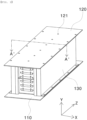
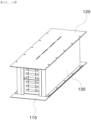
- FIG. 1 is an external perspective view of a battery module according to a first preferred embodiment of the present invention when viewed in a direction toward one side of the battery module
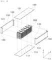
- FIG. 2 is an exploded perspective view of the battery module shown in FIG. 1 .
- the battery module according to the first embodiment of the present invention has an approximately hexahedral shape, and is configured to have a structure in which a cell stack 200 is received in a space defined inside a protective case 100 made of a metal material. A detailed description of the cell stack 200 will be described below.
- the protective case 100 includes a lower cover 110 located under the cell stack 200, an upper cover 120 located above the cell stack 200, and a pair of side covers 130 located at sides of the cell stack 200.
- the upper cover 120 which is configured to protect the upper part of the cell stack 200 and which is flat, is provided in a middle portion thereof with a plurality of second perforated portions 121 formed in a longitudinal direction (Z-axis direction).
- the second perforated portions 121 serve as a passage configured to allow heat to be discharged therethrough together with vent gas.
- vent gas when high-pressure vent gas is discharged, air in the protective case 100 is discharged together with the vent gas, whereby it is possible to prevent outbreak of fire.
- each of the second perforated portions 121 may be circular.
- the lower cover 110 it is more preferable for the lower cover 110 to also be provided with first perforated portions 111 formed in the longitudinal direction (Z-axis direction) so as to perform the same function as the second perforated portions 121.
- Each of the pair of side covers 130 that face each other in a state of being spaced apart from each other by a distance slightly greater than the width (X-axis direction) of the cell stack 200 includes a vertical plate 131, a horizontal extension plate 132, and a pair of bent plates 133.
- the side cover 130 prevents ejection of thermal runaway products, such as flare and spark, outside the protective case 100, and guides discharge of vent gas and heat through the second perforated portions 121 of the upper cover 120 and/or the first perforated portions 111 of the lower cover 110. Since air with which the interior of protective case 100 is filled is also discharged in this process, no flame is generated.
- the vertical plate 131 is slightly spaced apart from the cell stack 200 such that an air thermal insulation layer is formed.
- a lower end of the vertical plate 131 is located in close contact with the lower cover 110, and an upper end of the vertical plate 131 is located in close contact with the upper cover 120.
- the pair of bent plates 133 is located at opposite side ends of the vertical plate 131, i.e. in the vicinity of opposite corners of the cell stack 200.
- Each of the bent plates 133 is formed in an L-shape open at one side, and the bent plates face each other.
- the horizontal extension plate 132 which is bent outwards from each of the upper end and the lower end of the vertical plate 131, is provided for fastening between the lower cover 110 and the upper cover 120, and may be omitted as needed.
- the lower cover 110, the upper cover 120, and the pair of side covers 130 are shown as being coupled to each other after being separately manufactured in the drawings, the lower cover 110 and the pair of side covers 130 or the upper cover 120 and the pair of side covers 130 may be integrally manufactured and then the assembly process may be performed.
- FIG. 3 is an exploded perspective view of the cell stack in the battery module shown in FIG. 1
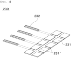
- FIG. 4 is an exploded perspective view of a pressing retention unit
- FIG. 5 is an exploded perspective view illustrating a coupling structure between a side cover and a busbar holder.
- the cell stack 200 includes a plurality of battery cells 210 stacked in a vertical direction, one or more shock absorption pads 220, one or more pressing layers 230, a busbar holder 240, and a busbar 250.
- the battery cell 210 may be a pouch-shaped battery cell, and includes a cell case configured to receive an electrode assembly (not shown) therein and a pair of electrode leads.
- the electrode assembly may be a jelly-roll type assembly, which is configured to have a structure in which a long sheet type positive electrode and a long sheet type negative electrode are wound in the state in which a separator is interposed therebetween, a stacked type assembly, which is configured to have a structure in which a rectangular positive electrode and a rectangular negative electrode are stacked in the state in which a separator is interposed therebetween, a stacked and folded type assembly, which is configured to have a structure in which unit cells are wound using a long separation film, or a laminated and stacked type assembly, which is configured to have a structure in which battery cells are stacked in the state in which a separator is interposed therebetween and are then attached to each other.
- the present invention is not limited thereto.
- an electrolyte may be replaced by a solid electrolyte or a gel type quasi-solid electrolyte obtained by adding an additive to a solid electrolyte, the gel type quasi-solid electrolyte having an intermediate phase between a liquid and a solid, in addition to a liquid electrolyte, which is commonly used.
- the electrode assembly is received in the cell case, and the cell case is generally configured to have a laminate sheet structure including an inner layer, a metal layer, and an outer layer.
- the inner layer is disposed in direct contact with the electrode assembly, and therefore the inner layer must exhibit high insulation properties and high resistance to an electrolytic solution.
- the inner layer must exhibit high sealability in order to hermetically seal the cell case from the outside, i.e. a thermally-bonded sealed portion between inner layers must exhibit excellent thermal bonding strength.
- the inner layer may be made of a material selected from among a polyolefin-based resin, such as polypropylene, polyethylene, polyethylene acrylate, or polybutylene, a polyurethane resin, and a polyimide resin, which exhibit excellent chemical resistance and high sealability.
- a polyolefin-based resin such as polypropylene, polyethylene, polyethylene acrylate, or polybutylene, a polyurethane resin, and a polyimide resin, which exhibit excellent chemical resistance and high sealability.
- polypropylene which exhibits excellent mechanical-physical properties, such as tensile strength, rigidity, surface hardness, and resistance to impact strength, and excellent chemical resistance, is the most preferably used.
- the metal layer which is disposed so as to abut the inner layer, corresponds to a barrier layer configured to prevent moisture or various kinds of gas from permeating into the battery from the outside.
- An aluminum thin film which is light and easily shapeable, may be used as a preferred material for the metal layer.
- the outer layer is provided on the other surface of the metal layer.
- the outer layer may be made of a heat-resistant polymer that exhibits excellent tensile strength, resistance to moisture permeation, and resistance to air transmission such that the outer layer exhibits high heat resistance and chemical resistance while protecting the electrode assembly.
- the outer layer may be made of nylon or polyethylene terephthalate.
- the present invention is not limited thereto.
- the pair of electrode leads is constituted by a positive electrode lead and a negative electrode lead, which may be exposed outwards from the cell case in a state of being electrically connected to a positive electrode tab and a negative electrode tab of the cell assembly, respectively, or may be directly connected to the cell assembly in the state in which the tabs are omitted.
- the one or more shock absorption pads 220 are located on one or more of the upper part and the lower part of the stacked battery cells 210, and may be interposed between the battery cells 210 as needed.
- the shock absorption pad 220 may be made of a material that has a volume easily changed depending on external force applied thereto, such as sponge or non-woven fabric.
- the pressing layer 230 which includes a pressing pad 231 and a reinforcement frame 232, presses one or more of the upper part and the lower part of the stacked battery cells 210. After the shock absorption pad 220 is mounted, the pressing layer 230 is located outside the shock absorption pad 220 to uniformly press all surfaces of the battery cell 210. In addition, the pressing layer prevents electrical conduction between the protective case 100, which is made of a metal material, and the battery cells 210.
- the pressing pad 231 be provided in one surface thereof with a recess 231' depressed so as to have a predetermined depth and width in a lateral direction (X-axis direction), it is more preferable that the pressing pad 231 be provided in one surface thereof with a plurality of recesses formed so as to be spaced apart from each other in a longitudinal direction (Z-axis direction), and it is most preferable that the reinforcement frame 232, which is bent so as to have a predetermined shape in a state of being open at one side thereof such that the section of the reinforcement frame is an approximately "V", "U”, or " " shape and which is made of a metal material, be seated in the recess 231'.
- the pressing pad 231 may be made of plastic in order to achieve light weight and insulation of the battery module. When swelling occurs, however, the pressing pad 231 melts away due to high temperature, whereby the battery cells 210 come into close contact with the inner surfaces of the lower cover 110 and the upper cover 120.
- the busbar 250 which is configured to electrically connect the leads of the battery cells 210 to each other, is a flat metal plate having slits, through which the leads extend, formed therein.
- the busbar holder 240 includes a flat main plate 241 having one or more slits formed therein, wing portions 242 connected to opposite side vertical ends of the main plate 241, and an auxiliary plate 243 configured to connect the pair of wing portions 242 to each other.
- each of the wing portions 242 it is preferable for each of the wing portions 242 to be bent in a predetermined shape so as to be brought into close contact with a corresponding one of the bent plates 133.
- a cell stack 200 in which a reinforcement frame 232, a shock absorption pad 220, a plurality of battery cells 210, a shock absorption pad 220, and a reinforcement frame 232 are stacked in that order, is prepared, leads of the battery cells 210 extends through slits of a busbar holder 240 made of an insulating material.
- the electrode leads extend through slits of a busbar 250, are bent, and are fixed using a known bonding method, such as welding.
- the cell stack 200 prepared as described above is received so as to be wrapped by a lower cover 110, an upper cover 120, and a pair of side covers 130.
- bent plates 133 of the side cover 130 come into close contact with wing portions 242 of the busbar holder 240, and the main plate 241 is slightly depressed in a direction toward the electrode leads.
- the busbar holder 240 performs the function of covering the front surface and the rear surface of the battery module.
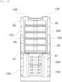
- FIG. 6 is a perspective view of the battery module shown in FIG. 1 when viewed from the front in the state in which the upper cover is removed therefrom
- FIG. 7 is a plan view of the battery module shown in FIG. 1 when viewed from above in the state in which the upper cover is removed therefrom.
- the battery module according to the present invention further includes a first space portion S1 to a third space portion S3 together with the bent plates 133 described above.
- the first space portion S1 and the second space portion S2 are formed between the pair of bent plates 133
- the third space portion S3 is formed between the vertical side surface of the cell stack 200 in the longitudinal direction and the vertical plate 131.
- flare or spark is gathered in one or more of the first space portion S1 to the third space portion S3 located on the right side, particularly in the first space portion S1 and the second space portion S2, in an interrupted state. Consequently, the flare or the spark cannot move not only to the front or the rear at which the busbar is located but also to the left side of the battery cell 210.
- vent gas that is generated moves to the first space portion S1 located at the front and the second space portion S2 located at the rear, and is then discharged to the vicinity of the busbar holder 240.
- vent gas moves upwards or downwards along the vertical plate 131, moves to the space portion inside the reinforcement frame 232, and is discharged to the outside through the second perforated portions 121 of the upper cover 120 and the first perforated portions 111 of the lower cover 110. At this time, it is obvious that heat is discharged to the outside through the above path together with the vent gas.
- FIG. 8 is a sectional view showing various modifications of the side cover
- FIG. 9 is a sectional view showing other modifications of the side cover.
- the bent plate 133 of the side cover 130 may be deformed so as to capture flare and spark. That is, instead of the L-shaped section according to the first preferred embodiment, the bent plate 133 may be configured to be bent at various different angles or may include a curved portion.
- the horizontal section of the bent plate may be deformed so as to have a shape of " “, " ", “ “, “ “ or “ “.”
- the section of the bent plate is not limited to the above shapes as long as it is possible to achieve the same object and function.
- busbar holder 240 may also be deformed so as to correspond to the external shape of the deformed bent plate 133.
- FIG. 10 is an external perspective view of a battery module according to a second preferred embodiment of the present invention when viewed in a direction toward one side of the battery module.
- the battery module according to the second embodiment is identical in construction to the battery module according to the first embodiment except for the external shape of the second perforated portions 121 of the upper cover 120 and the first perforated portions 111 of the lower cover 110.
- the first perforated portions 111 and the second perforated portions 121 according to the second embodiment may be formed such that circular holes and rectangular slits are alternately arranged.
- the second perforated portions 121 of the upper cover 120 may be formed such that circular holes and rectangular slits are alternately arranged while the first perforated portions 111 of the lower cover 110 may be formed as only circular holes, and vice versa.
- FIG. 11 is an external perspective view of a battery module according to a third preferred embodiment of the present invention when viewed in a direction toward one side of the battery module.
- the battery module according to the third embodiment is identical in construction to the battery module according to the first embodiment except for the external shape and position of the second perforated portions 121 of the upper cover 120 and the first perforated portions 111 of the lower cover 110.
- the first perforated portions 111 and the second perforated portions 121 according to the third embodiment are formed as rectangular slits. It is preferable for the first perforated portions and the second perforated portions to be located in a lateral direction of the upper cover, specifically along vertical extension lines of the reinforcement frames 232, such that vent gas and air can be rapidly discharged to the outside, and it is more preferable for the first perforated portions and the second perforated portions to be formed in the same number as the reinforcement frames 232.
- the second perforated portions 121 of the upper cover 120 may be formed as only rectangular slits while the first perforated portions 111 of the lower cover 110 may be formed as only circular holes, and vice versa.
- first perforated portions 111 and/or the second perforated portions 121 may be further provided with mesh nets.
- mesh nets 121(a) When the mesh nets 121(a) are mounted, it is possible to inhibit relatively large-sized thermal runaway products, such as flare and spark, from being ejected out of the upper cover 120 and/or the lower cover 110.
- FIG. 12 is an external perspective view of a battery module according to a fourth preferred embodiment of the present invention when viewed in a direction toward one side of the battery module.
- the battery module according to the fourth embodiment is identical in construction to the battery module according to the third embodiment except for the external shape and position of the second perforated portions 121 of the upper cover 120.
- the second perforated portions 121 according to the fourth embodiment are formed so as to have the shape of rectangular slits.
- the second perforated portions 121 it is preferable for the second perforated portions 121 to be located in plural in a longitudinal direction of the upper cover, specifically along a vertical extension line of the third space portion S3 formed as the result of the vertical plate 131 of the side cover 130 and the cell stack 200 being spaced apart from each other by a predetermined distance, such that vent gas and air can be rapidly discharged to the outside, and it is more preferable for the second perforated portions 121 to be further provided with mesh nets 121(a).
- the first perforated portions 111 of the lower cover 110 may also be further provided with mesh nets.
- FIG. 13 is an external perspective view of a battery module according to a fifth preferred embodiment of the present invention when viewed in a direction toward one side of the battery module.
- the battery module according to a fifth preferred embodiment has a combination of the second perforated portions 121 of the upper cover 120 according to the third embodiment and the second perforated portions 121 according to the fourth embodiment, and the shape and position thereof are the same as above. Therefore, a description thereof will be omitted.
- a plurality of battery modules may be disposed side by side or may be stacked in the vertical direction.
- the battery module having the above construction may be received in a separate case to constitute a single battery pack, and the battery module or the battery pack may be used in various facilities or devices including large-capacity power sources, such as an energy storage system, an electric vehicle, a hybrid electric vehicle, and a plug-in hybrid electric vehicle.
- large-capacity power sources such as an energy storage system, an electric vehicle, a hybrid electric vehicle, and a plug-in hybrid electric vehicle.
Landscapes
- Chemical & Material Sciences (AREA)
- Chemical Kinetics & Catalysis (AREA)
- Electrochemistry (AREA)
- General Chemical & Material Sciences (AREA)
- Engineering & Computer Science (AREA)
- Manufacturing & Machinery (AREA)
- Inorganic Chemistry (AREA)
- Battery Mounting, Suspending (AREA)
- Connection Of Batteries Or Terminals (AREA)
- Secondary Cells (AREA)
- Gas Exhaust Devices For Batteries (AREA)
Claims (21)
- Batteriemodul, umfassend:einen Zellenstapel (200), welcher eine Mehrzahl von Batteriezellen (210) umfasst, welche in einer vertikalen Richtung gestapelt sind; undein Schutzgehäuse (100), welches dazu eingerichtet ist, den Zellenstapel (200) aufzunehmen,wobei das Schutzgehäuse (100) eine untere Abdeckung (110), welche unterhalb des Zellenstapels (200) angeordnet ist, eine obere Abdeckung (120), welche oberhalb des Zellenstapels (200) angeordnet ist, und ein Paar von Seitenabdeckungen (130) umfasst, welche an Seiten des Zellenstapels (200) angeordnet sind, undwobei jede aus den Seitenabdeckungen (130) an einer Innenseite davon mit einer Struktur bereitgestellt ist, welche dazu eingerichtet ist, ein Ausstoßen von Flammen und Funken, welche durch ein Anschwellen generiert werden, an die Außenseite des Schutzgehäuses zu verhindern,dadurch gekennzeichnet, dass jede Seitenabdeckung (130) umfasst:eine vertikale Platte (131), welche ein unteres Ende, welches in nahem Kontakt mit der unteren Abdeckung (110) angeordnet ist und ein oberes Ende aufweist, welches in nahem Kontakt mit der oberen Abdeckung (120) angeordnet ist; undein Paar von gebogenen Platten (133), welche an gegenüberliegenden Seitenenden der vertikalen Platte (131) gebildet sind, um in einer vorbestimmten Form gebogen und/oder gekrümmt zu sein und zueinander zu weisen,wobei der Zellenstapel (200) umfasst:die Mehrzahl von Batteriezellen (210), welche in der vertikalen Richtung gestapelt sind;ein oder mehr schockabsorbierende Pads (220), welche an einem oder mehreren aus dem oberen Teil und dem unteren Teil der gestapelten Batteriezellen (210) angeordnet sind;eine Pressschicht (230), welche außerhalb der schockabsorbierenden Pads (220) angeordnet ist, um alle Flächen der Batteriezellen (210) uniform zu pressen, welche an wenigstens einem aus einem oberen Teil und einem unteren Teil der gestapelten Batteriezellen (210) angeordnet ist,eine Sammelschiene (250), welche dazu eingerichtet ist, positiven Elektrodenleitungen und negativen Elektrodenleitungen der Mehrzahl von Batteriezellen (210) zu ermöglichen, daran verbunden zu sein; undein Paar von Sammelschienenhaltern (240), welche zwischen den positiven Elektrodenleitungen und der Sammelschiene (250) beziehungsweise zwischen den negativen Elektrodenleitungen und der Sammelschiene (250) eingefügt sind,wobei die Pressschicht (230) ein Presspad (231) und einen Verstärkungsrahmen (232) umfasst.
- Batteriemodul nach Anspruch 1, wobei die vertikale Platte (131) der Seitenabdeckung (130) und der Zellenstapel (200) um einen vorbestimmten Abstand voneinander beabstandet sind, um einen dritten Raumabschnitt (S3) zu bilden.
- Batteriemodul nach Anspruch 1, wobei jeder aus den Sammelschienenhaltern (240) umfasst:eine flache Hauptplatte (241), welche einen oder mehr Schlitze aufweist, welche darin gebildet sind; undFlügelabschnitte (242), welche mit gegenüberliegenden Seiten-Vertikal-Enden der Hauptplatte (241) verbunden sind.
- Batteriemodul nach Anspruch 3, wobei jeder der Flügelabschnitte (242) gebogen ist, um eine vorbestimmte Form aufzuweisen.
- Batteriemodul nach Anspruch 1, wobei das Presspad (231) in einer Fläche davon mit einer Ausnehmung (231') bereitgestellt ist, und
wobei der Verstärkungsrahmen (232) in die Ausnehmung (231') gesetzt ist. - Batteriemodul nach Anspruch 5, wobei das Presspad (231) an jedem aus dem oberen Teil und dem unteren Teil der gestapelten Batteriezellen (210) angeordnet ist,wobei die Ausnehmung (231') des Presspads (231), welches an dem oberen Teil der gestapelten Batteriezellen (210) angeordnet ist, nach oben weist, undwobei die Ausnehmung (231') des Presspads (231), welches an dem unteren Teil der gestapelten Batteriezellen (210) angeordnet ist, nach unten weist.
- Batteriemodul nach Anspruch 5, wobei die Ausnehmung (231') und der Verstärkungsrahmen (232) identische vertikale Schnittformen aufweisen.
- Batteriemodul nach Anspruch 7, wobei jedes aus der Ausnehmung (231') und dem Verstärkungsrahmen (232) eine vertikale Schnittform von "V", "U" oder "" aufweist.

- Batteriemodul nach Anspruch 6, wobei das Presspad (231) aus einem isolierenden Kunststoffmaterial hergestellt ist, und
wobei der Verstärkungsrahmen (232) aus einem metallischen Material hergestellt ist. - Batteriemodul nach Anspruch 1, wobei die obere Abdeckung (120) mit einem zweiten perforierten Abschnitt (121) bereitgestellt ist.
- Batteriemodul nach Anspruch 10, wobei der zweite perforierte Abschnitt (121) eine rechteckige Schlitzform aufweist.
- Batteriemodul nach Anspruch 10, wobei der zweite perforierte Abschnitt (121) in einer longitudinalen Richtung der oberen Abdeckung gebildet ist.
- Batteriemodul nach Anspruch 12, wobei der zweite perforierte Abschnitt (121) an einer vertikalen Erstreckungslinie des dritten Raumabschnitts (S3) angeordnet ist.
- Batteriemodul nach Anspruch 10, wobei der zweite perforierte Abschnitt (121) in einer lateralen Richtung der oberen Abdeckung (120) gebildet ist.
- Batteriemodul nach Anspruch 14, wobei der zweite perforierte Abschnitt (121) an einer vertikalen Erstreckungslinie des Verstärkungsrahmens (232) angeordnet ist.
- Batteriemodul nach Anspruch 14, wobei der zweite perforierte Abschnitt (121) in einer gleichen Anzahl zu dem Verstärkungsrahmen (232) gebildet ist.
- Batteriemodul nach Anspruch 10, wobei der zweite perforierte Abschnitt (121) kreisförmig ist.
- Batteriemodul nach Anspruch 10, wobei der zweite perforierte Abschnitt (121) mit einem Maschennetz (121') bereitgestellt ist.
- Batteriemodul nach Anspruch 1, wobei die untere Abdeckung (110) mit einem ersten perforierten Abschnitt (111) bereitgestellt ist.
- Batteriepack, umfassend das Batteriemodul nach einem der Ansprüche 1 bis 19.
- Energiespeicherungssystem, welches den Batteriepack nach Anspruch 20 aufweist.
Priority Applications (1)
| Application Number | Priority Date | Filing Date | Title |
|---|---|---|---|
| EP25166588.1A EP4553979A3 (de) | 2020-07-02 | 2021-07-02 | Batteriemodul mit tasche zur erfassung von während der quellung ausgestossenem fackel und funken |
Applications Claiming Priority (3)
| Application Number | Priority Date | Filing Date | Title |
|---|---|---|---|
| KR1020200081659A KR102830526B1 (ko) | 2020-07-02 | 2020-07-02 | 스웰링시 분출되는 플레어와 스파크를 포집할 수 있는 포켓이 구비된 전지 모듈 |
| KR1020200105297A KR102813264B1 (ko) | 2020-08-21 | 2020-08-21 | 스웰링시 분출되는 플레어와 스파크를 포집할 수 있는 포켓이 구비된 전지 모듈 |
| PCT/KR2021/008391 WO2022005239A1 (ko) | 2020-07-02 | 2021-07-02 | 스웰링시 분출되는 플레어와 스파크를 포집할 수 있는 포켓이 구비된 전지 모듈 |
Related Child Applications (2)
| Application Number | Title | Priority Date | Filing Date |
|---|---|---|---|
| EP25166588.1A Division EP4553979A3 (de) | 2020-07-02 | 2021-07-02 | Batteriemodul mit tasche zur erfassung von während der quellung ausgestossenem fackel und funken |
| EP25166588.1A Division-Into EP4553979A3 (de) | 2020-07-02 | 2021-07-02 | Batteriemodul mit tasche zur erfassung von während der quellung ausgestossenem fackel und funken |
Publications (3)
| Publication Number | Publication Date |
|---|---|
| EP4131618A1 EP4131618A1 (de) | 2023-02-08 |
| EP4131618A4 EP4131618A4 (de) | 2023-10-25 |
| EP4131618B1 true EP4131618B1 (de) | 2025-06-11 |
Family
ID=79317061
Family Applications (2)
| Application Number | Title | Priority Date | Filing Date |
|---|---|---|---|
| EP25166588.1A Pending EP4553979A3 (de) | 2020-07-02 | 2021-07-02 | Batteriemodul mit tasche zur erfassung von während der quellung ausgestossenem fackel und funken |
| EP21831718.8A Active EP4131618B1 (de) | 2020-07-02 | 2021-07-02 | Batteriemodul mit tasche zum sammeln von bei schwellung ausgestossenen streulichten und funken |
Family Applications Before (1)
| Application Number | Title | Priority Date | Filing Date |
|---|---|---|---|
| EP25166588.1A Pending EP4553979A3 (de) | 2020-07-02 | 2021-07-02 | Batteriemodul mit tasche zur erfassung von während der quellung ausgestossenem fackel und funken |
Country Status (9)
| Country | Link |
|---|---|
| US (1) | US20230128563A1 (de) |
| EP (2) | EP4553979A3 (de) |
| JP (1) | JP7523845B2 (de) |
| CN (1) | CN115461921B (de) |
| AU (1) | AU2021299624A1 (de) |
| ES (1) | ES3035641T3 (de) |
| HU (1) | HUE072385T2 (de) |
| PL (1) | PL4131618T3 (de) |
| WO (1) | WO2022005239A1 (de) |
Families Citing this family (4)
| Publication number | Priority date | Publication date | Assignee | Title |
|---|---|---|---|---|
| KR102825807B1 (ko) * | 2021-01-15 | 2025-06-25 | 주식회사 엘지에너지솔루션 | 화재 발생 및 폭발을 방지할 수 있는 구조를 갖는 배터리 모듈, 그리고 이를 포함하는 배터리 팩 및 ess |
| EP4557466A4 (de) * | 2022-08-31 | 2025-12-03 | Lg Energy Solution Ltd | Batteriepack und vorrichtung damit |
| EP4475302B1 (de) | 2022-10-12 | 2026-02-18 | LG Energy Solution, Ltd. | Batteriemodul und batteriepack sowie energiespeichersystem damit |
| CN119404363A (zh) * | 2023-04-28 | 2025-02-07 | 株式会社Lg新能源 | 电池组和包括该电池组的车辆 |
Family Cites Families (15)
| Publication number | Priority date | Publication date | Assignee | Title |
|---|---|---|---|---|
| KR101749191B1 (ko) * | 2013-05-29 | 2017-06-20 | 삼성에스디아이 주식회사 | 배터리 모듈 |
| JP2015162285A (ja) | 2014-02-26 | 2015-09-07 | 日産自動車株式会社 | 電池モジュール |
| KR101787638B1 (ko) | 2014-11-05 | 2017-10-19 | 주식회사 엘지화학 | 이중 측벽 구조를 가지는 카트리지 프레임 및 이를 포함하는 배터리 모듈 |
| KR101776898B1 (ko) * | 2014-12-24 | 2017-09-08 | 주식회사 엘지화학 | 배터리 모듈 |
| KR102058689B1 (ko) * | 2015-09-22 | 2019-12-23 | 주식회사 엘지화학 | 배터리 모듈, 이러한 배터리 모듈을 포함하는 배터리 팩 및 이러한 배터리 팩을 포함하는 자동차 |
| KR102154361B1 (ko) * | 2015-12-09 | 2020-09-09 | 주식회사 엘지화학 | 엔드 플레이트의 구조가 개선된 배터리 모듈 및 이를 위한 엔드 플레이트 부재 |
| KR102091770B1 (ko) * | 2016-05-31 | 2020-03-23 | 주식회사 엘지화학 | 배터리 모듈, 이러한 배터리 모듈을 포함하는 배터리 팩 및 이러한 배터리 팩을 포함하는 자동차 |
| KR20190054300A (ko) * | 2017-11-13 | 2019-05-22 | 현대자동차주식회사 | 배터리 |
| KR102159347B1 (ko) | 2017-11-14 | 2020-09-23 | 주식회사 엘지화학 | 배터리 셀 가압형 엔드 플레이트와 확장형 센싱 하우징 구조가 적용된 배터리 모듈 |
| KR102282482B1 (ko) | 2018-02-06 | 2021-07-26 | 주식회사 엘지에너지솔루션 | 배터리 모듈 및 이를 포함하는 배터리 팩 |
| KR102328730B1 (ko) * | 2018-04-20 | 2021-11-17 | 주식회사 엘지에너지솔루션 | 직/병렬 연결을 용이하게 하는 구조를 갖는 배터리 모듈 및 이를 포함하는 배터리 팩 |
| KR102629460B1 (ko) * | 2018-06-04 | 2024-01-25 | 삼성에스디아이 주식회사 | 배터리 팩 |
| KR102663019B1 (ko) | 2018-07-25 | 2024-05-07 | 삼성에스디아이 주식회사 | 배터리 팩 |
| KR20200081659A (ko) | 2018-12-28 | 2020-07-08 | 동서울대학교 산학협력단 | 은행 막걸리의 제조방법 |
| KR102173515B1 (ko) | 2019-02-28 | 2020-11-03 | 송권규 | 공기청정기 |
-
2021
- 2021-07-02 EP EP25166588.1A patent/EP4553979A3/de active Pending
- 2021-07-02 HU HUE21831718A patent/HUE072385T2/hu unknown
- 2021-07-02 JP JP2022566245A patent/JP7523845B2/ja active Active
- 2021-07-02 PL PL21831718.8T patent/PL4131618T3/pl unknown
- 2021-07-02 EP EP21831718.8A patent/EP4131618B1/de active Active
- 2021-07-02 AU AU2021299624A patent/AU2021299624A1/en active Pending
- 2021-07-02 ES ES21831718T patent/ES3035641T3/es active Active
- 2021-07-02 WO PCT/KR2021/008391 patent/WO2022005239A1/ko not_active Ceased
- 2021-07-02 CN CN202180030080.3A patent/CN115461921B/zh active Active
-
2022
- 2022-12-23 US US18/088,390 patent/US20230128563A1/en active Pending
Also Published As
| Publication number | Publication date |
|---|---|
| US20230128563A1 (en) | 2023-04-27 |
| HUE072385T2 (hu) | 2025-11-28 |
| WO2022005239A1 (ko) | 2022-01-06 |
| EP4131618A4 (de) | 2023-10-25 |
| JP7523845B2 (ja) | 2024-07-29 |
| AU2021299624A1 (en) | 2022-11-17 |
| JP2023524705A (ja) | 2023-06-13 |
| ES3035641T3 (en) | 2025-09-05 |
| EP4131618A1 (de) | 2023-02-08 |
| PL4131618T3 (pl) | 2025-09-01 |
| EP4553979A3 (de) | 2025-07-23 |
| EP4553979A2 (de) | 2025-05-14 |
| CN115461921A (zh) | 2022-12-09 |
| CN115461921B (zh) | 2025-05-06 |
Similar Documents
| Publication | Publication Date | Title |
|---|---|---|
| EP4087039B1 (de) | Batteriemodul mit trennwand und thermischer dämmschicht zur feuerunterdrückung | |
| CN216698555U (zh) | 电池模块和包括该电池模块的电池组 | |
| EP4131618B1 (de) | Batteriemodul mit tasche zum sammeln von bei schwellung ausgestossenen streulichten und funken | |
| KR102830526B1 (ko) | 스웰링시 분출되는 플레어와 스파크를 포집할 수 있는 포켓이 구비된 전지 모듈 | |
| EP2808920B1 (de) | Batteriemodul mit erhöhter sicherheit und batteriepack damit | |
| KR102813264B1 (ko) | 스웰링시 분출되는 플레어와 스파크를 포집할 수 있는 포켓이 구비된 전지 모듈 | |
| EP4254626A1 (de) | Batteriepack und vorrichtung damit | |
| KR102677094B1 (ko) | 배터리 모듈, 이를 포함하는 배터리 팩과 에너지 저장 시스템 | |
| EP4250452A1 (de) | Batteriepack und vorrichtung damit | |
| KR101913866B1 (ko) | 이차전지 모듈 | |
| EP4475302B1 (de) | Batteriemodul und batteriepack sowie energiespeichersystem damit | |
| EP4636928A1 (de) | Batteriemodul und batteriepack sowie fahrzeug damit | |
| CN121263910A (zh) | 电池组和包括该电池组的车辆 | |
| KR20250122676A (ko) | 전지팩 및 이를 포함하는 디바이스 | |
| KR20250098949A (ko) | 배터리 팩 및 이를 포함하는 자동차 | |
| CN121359303A (zh) | 电池模块 | |
| CN119096404A (zh) | 电池模块以及包括该电池模块的电池组和车辆 | |
| CN118975026A (zh) | 电池模块以及包括该电池模块的电池组和能量存储系统 | |
| KR20140011441A (ko) | 안전성이 향상된 중대형 전지모듈 |
Legal Events
| Date | Code | Title | Description |
|---|---|---|---|
| STAA | Information on the status of an ep patent application or granted ep patent |
Free format text: STATUS: THE INTERNATIONAL PUBLICATION HAS BEEN MADE |
|
| PUAI | Public reference made under article 153(3) epc to a published international application that has entered the european phase |
Free format text: ORIGINAL CODE: 0009012 |
|
| STAA | Information on the status of an ep patent application or granted ep patent |
Free format text: STATUS: REQUEST FOR EXAMINATION WAS MADE |
|
| 17P | Request for examination filed |
Effective date: 20221024 |
|
| AK | Designated contracting states |
Kind code of ref document: A1 Designated state(s): AL AT BE BG CH CY CZ DE DK EE ES FI FR GB GR HR HU IE IS IT LI LT LU LV MC MK MT NL NO PL PT RO RS SE SI SK SM TR |
|
| DAV | Request for validation of the european patent (deleted) | ||
| DAX | Request for extension of the european patent (deleted) | ||
| A4 | Supplementary search report drawn up and despatched |
Effective date: 20230921 |
|
| RIC1 | Information provided on ipc code assigned before grant |
Ipc: H01M 50/289 20210101ALI20230915BHEP Ipc: H01M 50/211 20210101ALI20230915BHEP Ipc: H01M 50/502 20210101ALI20230915BHEP Ipc: H01M 50/20 20210101ALI20230915BHEP Ipc: H01M 50/342 20210101ALI20230915BHEP Ipc: H01M 50/383 20210101AFI20230915BHEP |
|
| STAA | Information on the status of an ep patent application or granted ep patent |
Free format text: STATUS: EXAMINATION IS IN PROGRESS |
|
| 17Q | First examination report despatched |
Effective date: 20240620 |
|
| GRAP | Despatch of communication of intention to grant a patent |
Free format text: ORIGINAL CODE: EPIDOSNIGR1 |
|
| STAA | Information on the status of an ep patent application or granted ep patent |
Free format text: STATUS: GRANT OF PATENT IS INTENDED |
|
| INTG | Intention to grant announced |
Effective date: 20250130 |
|
| P01 | Opt-out of the competence of the unified patent court (upc) registered |
Free format text: CASE NUMBER: APP_6061/2025 Effective date: 20250205 |
|
| GRAS | Grant fee paid |
Free format text: ORIGINAL CODE: EPIDOSNIGR3 |
|
| GRAA | (expected) grant |
Free format text: ORIGINAL CODE: 0009210 |
|
| STAA | Information on the status of an ep patent application or granted ep patent |
Free format text: STATUS: THE PATENT HAS BEEN GRANTED |
|
| AK | Designated contracting states |
Kind code of ref document: B1 Designated state(s): AL AT BE BG CH CY CZ DE DK EE ES FI FR GB GR HR HU IE IS IT LI LT LU LV MC MK MT NL NO PL PT RO RS SE SI SK SM TR |
|
| REG | Reference to a national code |
Ref country code: GB Ref legal event code: FG4D |
|
| REG | Reference to a national code |
Ref country code: CH Ref legal event code: EP |
|
| REG | Reference to a national code |
Ref country code: IE Ref legal event code: FG4D |
|
| REG | Reference to a national code |
Ref country code: DE Ref legal event code: R096 Ref document number: 602021032234 Country of ref document: DE |
|
| PGFP | Annual fee paid to national office [announced via postgrant information from national office to epo] |
Ref country code: GB Payment date: 20250624 Year of fee payment: 5 |
|
| PGFP | Annual fee paid to national office [announced via postgrant information from national office to epo] |
Ref country code: BE Payment date: 20250623 Year of fee payment: 5 |
|
| PGFP | Annual fee paid to national office [announced via postgrant information from national office to epo] |
Ref country code: FR Payment date: 20250624 Year of fee payment: 5 |
|
| REG | Reference to a national code |
Ref country code: SE Ref legal event code: TRGR |
|
| PGFP | Annual fee paid to national office [announced via postgrant information from national office to epo] |
Ref country code: SE Payment date: 20250624 Year of fee payment: 5 |
|
| REG | Reference to a national code |
Ref country code: ES Ref legal event code: FG2A Ref document number: 3035641 Country of ref document: ES Kind code of ref document: T3 Effective date: 20250905 |
|
| PG25 | Lapsed in a contracting state [announced via postgrant information from national office to epo] |
Ref country code: FI Free format text: LAPSE BECAUSE OF FAILURE TO SUBMIT A TRANSLATION OF THE DESCRIPTION OR TO PAY THE FEE WITHIN THE PRESCRIBED TIME-LIMIT Effective date: 20250611 |
|
| PGFP | Annual fee paid to national office [announced via postgrant information from national office to epo] |
Ref country code: ES Payment date: 20250822 Year of fee payment: 5 |
|
| PGFP | Annual fee paid to national office [announced via postgrant information from national office to epo] |
Ref country code: DE Payment date: 20250624 Year of fee payment: 5 |
|
| REG | Reference to a national code |
Ref country code: LT Ref legal event code: MG9D |
|
| PG25 | Lapsed in a contracting state [announced via postgrant information from national office to epo] |
Ref country code: NO Free format text: LAPSE BECAUSE OF FAILURE TO SUBMIT A TRANSLATION OF THE DESCRIPTION OR TO PAY THE FEE WITHIN THE PRESCRIBED TIME-LIMIT Effective date: 20250911 Ref country code: GR Free format text: LAPSE BECAUSE OF FAILURE TO SUBMIT A TRANSLATION OF THE DESCRIPTION OR TO PAY THE FEE WITHIN THE PRESCRIBED TIME-LIMIT Effective date: 20250912 |
|
| PGFP | Annual fee paid to national office [announced via postgrant information from national office to epo] |
Ref country code: PL Payment date: 20250625 Year of fee payment: 5 |
|
| REG | Reference to a national code |
Ref country code: NL Ref legal event code: MP Effective date: 20250611 |
|
| PG25 | Lapsed in a contracting state [announced via postgrant information from national office to epo] |
Ref country code: BG Free format text: LAPSE BECAUSE OF FAILURE TO SUBMIT A TRANSLATION OF THE DESCRIPTION OR TO PAY THE FEE WITHIN THE PRESCRIBED TIME-LIMIT Effective date: 20250611 |
|
| PGFP | Annual fee paid to national office [announced via postgrant information from national office to epo] |
Ref country code: HU Payment date: 20250929 Year of fee payment: 5 |
|
| PG25 | Lapsed in a contracting state [announced via postgrant information from national office to epo] |
Ref country code: HR Free format text: LAPSE BECAUSE OF FAILURE TO SUBMIT A TRANSLATION OF THE DESCRIPTION OR TO PAY THE FEE WITHIN THE PRESCRIBED TIME-LIMIT Effective date: 20250611 |
|
| PGFP | Annual fee paid to national office [announced via postgrant information from national office to epo] |
Ref country code: AT Payment date: 20251020 Year of fee payment: 5 |
|
| PG25 | Lapsed in a contracting state [announced via postgrant information from national office to epo] |
Ref country code: RS Free format text: LAPSE BECAUSE OF FAILURE TO SUBMIT A TRANSLATION OF THE DESCRIPTION OR TO PAY THE FEE WITHIN THE PRESCRIBED TIME-LIMIT Effective date: 20250911 |
|
| PG25 | Lapsed in a contracting state [announced via postgrant information from national office to epo] |
Ref country code: LV Free format text: LAPSE BECAUSE OF FAILURE TO SUBMIT A TRANSLATION OF THE DESCRIPTION OR TO PAY THE FEE WITHIN THE PRESCRIBED TIME-LIMIT Effective date: 20250611 |
|
| PG25 | Lapsed in a contracting state [announced via postgrant information from national office to epo] |
Ref country code: NL Free format text: LAPSE BECAUSE OF FAILURE TO SUBMIT A TRANSLATION OF THE DESCRIPTION OR TO PAY THE FEE WITHIN THE PRESCRIBED TIME-LIMIT Effective date: 20250611 |
|
| REG | Reference to a national code |
Ref country code: HU Ref legal event code: AG4A Ref document number: E072385 Country of ref document: HU |
|
| PG25 | Lapsed in a contracting state [announced via postgrant information from national office to epo] |
Ref country code: PT Free format text: LAPSE BECAUSE OF FAILURE TO SUBMIT A TRANSLATION OF THE DESCRIPTION OR TO PAY THE FEE WITHIN THE PRESCRIBED TIME-LIMIT Effective date: 20251013 |
|
| REG | Reference to a national code |
Ref country code: AT Ref legal event code: MK05 Ref document number: 1803000 Country of ref document: AT Kind code of ref document: T Effective date: 20250611 |
|
| PG25 | Lapsed in a contracting state [announced via postgrant information from national office to epo] |
Ref country code: IS Free format text: LAPSE BECAUSE OF FAILURE TO SUBMIT A TRANSLATION OF THE DESCRIPTION OR TO PAY THE FEE WITHIN THE PRESCRIBED TIME-LIMIT Effective date: 20251011 |
|
| PG25 | Lapsed in a contracting state [announced via postgrant information from national office to epo] |
Ref country code: AT Free format text: LAPSE BECAUSE OF FAILURE TO SUBMIT A TRANSLATION OF THE DESCRIPTION OR TO PAY THE FEE WITHIN THE PRESCRIBED TIME-LIMIT Effective date: 20250611 Ref country code: SM Free format text: LAPSE BECAUSE OF FAILURE TO SUBMIT A TRANSLATION OF THE DESCRIPTION OR TO PAY THE FEE WITHIN THE PRESCRIBED TIME-LIMIT Effective date: 20250611 |
|
| PG25 | Lapsed in a contracting state [announced via postgrant information from national office to epo] |
Ref country code: CZ Free format text: LAPSE BECAUSE OF FAILURE TO SUBMIT A TRANSLATION OF THE DESCRIPTION OR TO PAY THE FEE WITHIN THE PRESCRIBED TIME-LIMIT Effective date: 20250611 |
|
| PG25 | Lapsed in a contracting state [announced via postgrant information from national office to epo] |
Ref country code: EE Free format text: LAPSE BECAUSE OF FAILURE TO SUBMIT A TRANSLATION OF THE DESCRIPTION OR TO PAY THE FEE WITHIN THE PRESCRIBED TIME-LIMIT Effective date: 20250611 |
|
| PG25 | Lapsed in a contracting state [announced via postgrant information from national office to epo] |
Ref country code: SK Free format text: LAPSE BECAUSE OF FAILURE TO SUBMIT A TRANSLATION OF THE DESCRIPTION OR TO PAY THE FEE WITHIN THE PRESCRIBED TIME-LIMIT Effective date: 20250611 |
|
| PG25 | Lapsed in a contracting state [announced via postgrant information from national office to epo] |
Ref country code: RO Free format text: LAPSE BECAUSE OF FAILURE TO SUBMIT A TRANSLATION OF THE DESCRIPTION OR TO PAY THE FEE WITHIN THE PRESCRIBED TIME-LIMIT Effective date: 20250611 |