EP4131601A1 - Battery module - Google Patents
Battery module Download PDFInfo
- Publication number
- EP4131601A1 EP4131601A1 EP21780088.7A EP21780088A EP4131601A1 EP 4131601 A1 EP4131601 A1 EP 4131601A1 EP 21780088 A EP21780088 A EP 21780088A EP 4131601 A1 EP4131601 A1 EP 4131601A1
- Authority
- EP
- European Patent Office
- Prior art keywords
- battery
- battery module
- separator
- stacking direction
- deformation
- Prior art date
- Legal status (The legal status is an assumption and is not a legal conclusion. Google has not performed a legal analysis and makes no representation as to the accuracy of the status listed.)
- Pending
Links
Images




Classifications
-
- H—ELECTRICITY
- H01—ELECTRIC ELEMENTS
- H01M—PROCESSES OR MEANS, e.g. BATTERIES, FOR THE DIRECT CONVERSION OF CHEMICAL ENERGY INTO ELECTRICAL ENERGY
- H01M50/00—Constructional details or processes of manufacture of the non-active parts of electrochemical cells other than fuel cells, e.g. hybrid cells
- H01M50/20—Mountings; Secondary casings or frames; Racks, modules or packs; Suspension devices; Shock absorbers; Transport or carrying devices; Holders
- H01M50/289—Mountings; Secondary casings or frames; Racks, modules or packs; Suspension devices; Shock absorbers; Transport or carrying devices; Holders characterised by spacing elements or positioning means within frames, racks or packs
- H01M50/291—Mountings; Secondary casings or frames; Racks, modules or packs; Suspension devices; Shock absorbers; Transport or carrying devices; Holders characterised by spacing elements or positioning means within frames, racks or packs characterised by their shape
-
- H—ELECTRICITY
- H01—ELECTRIC ELEMENTS
- H01M—PROCESSES OR MEANS, e.g. BATTERIES, FOR THE DIRECT CONVERSION OF CHEMICAL ENERGY INTO ELECTRICAL ENERGY
- H01M10/00—Secondary cells; Manufacture thereof
- H01M10/60—Heating or cooling; Temperature control
- H01M10/61—Types of temperature control
- H01M10/613—Cooling or keeping cold
-
- H—ELECTRICITY
- H01—ELECTRIC ELEMENTS
- H01M—PROCESSES OR MEANS, e.g. BATTERIES, FOR THE DIRECT CONVERSION OF CHEMICAL ENERGY INTO ELECTRICAL ENERGY
- H01M10/00—Secondary cells; Manufacture thereof
- H01M10/60—Heating or cooling; Temperature control
- H01M10/64—Heating or cooling; Temperature control characterised by the shape of the cells
- H01M10/647—Prismatic or flat cells, e.g. pouch cells
-
- H—ELECTRICITY
- H01—ELECTRIC ELEMENTS
- H01M—PROCESSES OR MEANS, e.g. BATTERIES, FOR THE DIRECT CONVERSION OF CHEMICAL ENERGY INTO ELECTRICAL ENERGY
- H01M10/00—Secondary cells; Manufacture thereof
- H01M10/60—Heating or cooling; Temperature control
- H01M10/65—Means for temperature control structurally associated with the cells
- H01M10/655—Solid structures for heat exchange or heat conduction
- H01M10/6556—Solid parts with flow channel passages or pipes for heat exchange
-
- H—ELECTRICITY
- H01—ELECTRIC ELEMENTS
- H01M—PROCESSES OR MEANS, e.g. BATTERIES, FOR THE DIRECT CONVERSION OF CHEMICAL ENERGY INTO ELECTRICAL ENERGY
- H01M10/00—Secondary cells; Manufacture thereof
- H01M10/60—Heating or cooling; Temperature control
- H01M10/65—Means for temperature control structurally associated with the cells
- H01M10/656—Means for temperature control structurally associated with the cells characterised by the type of heat-exchange fluid
- H01M10/6561—Gases
-
- H—ELECTRICITY
- H01—ELECTRIC ELEMENTS
- H01M—PROCESSES OR MEANS, e.g. BATTERIES, FOR THE DIRECT CONVERSION OF CHEMICAL ENERGY INTO ELECTRICAL ENERGY
- H01M50/00—Constructional details or processes of manufacture of the non-active parts of electrochemical cells other than fuel cells, e.g. hybrid cells
- H01M50/20—Mountings; Secondary casings or frames; Racks, modules or packs; Suspension devices; Shock absorbers; Transport or carrying devices; Holders
- H01M50/204—Racks, modules or packs for multiple batteries or multiple cells
- H01M50/207—Racks, modules or packs for multiple batteries or multiple cells characterised by their shape
- H01M50/209—Racks, modules or packs for multiple batteries or multiple cells characterised by their shape adapted for prismatic or rectangular cells
-
- H—ELECTRICITY
- H01—ELECTRIC ELEMENTS
- H01M—PROCESSES OR MEANS, e.g. BATTERIES, FOR THE DIRECT CONVERSION OF CHEMICAL ENERGY INTO ELECTRICAL ENERGY
- H01M50/00—Constructional details or processes of manufacture of the non-active parts of electrochemical cells other than fuel cells, e.g. hybrid cells
- H01M50/20—Mountings; Secondary casings or frames; Racks, modules or packs; Suspension devices; Shock absorbers; Transport or carrying devices; Holders
- H01M50/289—Mountings; Secondary casings or frames; Racks, modules or packs; Suspension devices; Shock absorbers; Transport or carrying devices; Holders characterised by spacing elements or positioning means within frames, racks or packs
- H01M50/293—Mountings; Secondary casings or frames; Racks, modules or packs; Suspension devices; Shock absorbers; Transport or carrying devices; Holders characterised by spacing elements or positioning means within frames, racks or packs characterised by the material
-
- Y—GENERAL TAGGING OF NEW TECHNOLOGICAL DEVELOPMENTS; GENERAL TAGGING OF CROSS-SECTIONAL TECHNOLOGIES SPANNING OVER SEVERAL SECTIONS OF THE IPC; TECHNICAL SUBJECTS COVERED BY FORMER USPC CROSS-REFERENCE ART COLLECTIONS [XRACs] AND DIGESTS
- Y02—TECHNOLOGIES OR APPLICATIONS FOR MITIGATION OR ADAPTATION AGAINST CLIMATE CHANGE
- Y02E—REDUCTION OF GREENHOUSE GAS [GHG] EMISSIONS, RELATED TO ENERGY GENERATION, TRANSMISSION OR DISTRIBUTION
- Y02E60/00—Enabling technologies; Technologies with a potential or indirect contribution to GHG emissions mitigation
- Y02E60/10—Energy storage using batteries
Definitions
- the present invention relates to a battery module.
- a battery module formed by electrically connecting a plurality of batteries to each other.
- an internal electrode body, an electrolyte, and the like degrade over time, and bulge due to deposition or oxidation of a metal material, and a change appears in an outer shape.
- PTL 1 discloses a battery module including a battery stack in which a plurality of batteries are stacked and an insulating sheet is interposed between the batteries, and end plates provided at both ends in the stacking direction of the battery stack.
- the present invention has been made in view of such circumstances, and an object of the present invention is to provide a technique for reducing a reaction force generated in a stacking direction in a battery module.
- a battery module includes: a battery stack in which a plurality of batteries are stacked; an end plate provided outside a battery at an end in a stacking direction of the plurality of batteries; and an end separator provided between the battery at the end and the end plate, the end separator being disposed in a part in the stacking direction and including a deformation allowing part in which deformation due to creep is larger than deformation of other parts.
- the safety of a battery module can be enhanced.
- Fig. 1 is a perspective view illustrating an appearance of battery module 100 according to an exemplary embodiment
- Fig. 2 is an exploded perspective view of a part of battery module 100.
- Battery module 100 includes housing 1 having a rectangular-parallelepiped shape, battery stack 2, separator 3, and end separator 4.
- end separator 4 is provided with a deformation allowing part in which the deformation due to the creep in the stacking direction is larger than the other parts, and the reaction force acting on the battery due to the creep of the deformation allowing part is reduced.
- Housing 1 includes end plate 11, side plate 12, base plate 13, and cover plate 14. End plates 11 are provided outside batteries 20 positioned at both ends of battery stack 2 in the stacking direction of batteries 20. Side plate 12 sandwiches end plate 11 and covers a side surface of battery stack 2. Base plate 13 is configured by covering a bottom of battery stack 2. Cover plate 14 covers an upper surface of battery stack 2.
- Battery stack 2 is housed inside housing 1.
- Battery stack 2 is formed by stacking a plurality of batteries 20 in one direction.
- Separator 3 formed of a resin material or the like in a sheet shape or a plate shape is provided between the batteries. Separator 3 electrically insulates each battery 20 of battery stack 2. Separator 3 may be considered to constitute a part of battery stack 2 because separator 3 is incorporated into and integrated with battery stack 2.
- Each battery 20 is a rechargeable secondary battery such as a lithium-ion battery, a nickel-metal-hydride battery, or a nickel-cadmium battery. Additionally, each battery 20 is a so-called prismatic battery, and has outer covering can 21 having a flat rectangular-parallelepiped shape. One surface of outer covering can 21 is provided with an opening having a substantially rectangular shape not illustrated, and an electrode body, an electrolyte, and the like are accommodated in outer covering can 21 through the opening. Sealing plate 21a that closes the opening of outer covering can 21 is disposed in the opening.
- Output terminal 22 of a positive electrode is disposed on sealing plate 21a at a position close to one end of sealing plate 21a in a longitudinal direction
- output terminal 22 of a negative electrode is disposed on sealing plate 21a at a position close to the other end of sealing plate 21a in the longitudinal direction.
- the pair of output terminals 22 is electrically connected to the corresponding one of a positive electrode plate and a negative electrode plate, constituting the electrode assembly.
- Respective output terminals 22 are inserted into through-holes (not illustrated) formed in sealing plate 21a.
- a seal member (not illustrated) having an insulating property is interposed between respective output terminals 22 and respective through-holes.
- sealing plate 21a is an upper surface of battery 20, and a bottom surface of outer covering can 21 facing sealing plate 21a is a lower surface of battery 20.
- Battery 20 has two main surfaces that connect the upper surface and the lower surface of battery 20 to each other.
- the main surfaces are surfaces having the largest area out of the six surfaces of battery 20.
- the main surfaces are long side surfaces connected to the long sides of the upper surface and the long sides of the lower surface. Two remaining surfaces except for the upper surface, the lower surface, and the two main surfaces are referred to as the side surfaces of battery 20.
- These side surfaces are a pair of short side surfaces connected to the short sides of the upper surface and the short sides of the lower surface. These directions and positions are defined for the sake of convenience. Therefore, for example, the part defined as the upper surface in the present invention does not necessarily mean a part located above the part defined as the lower surface.
- Valve 24 is disposed on sealing plate 21a between the pair of output terminals 22. Valve 24 is also referred to as a safety valve. Valve 24 is a mechanism for releasing a gas in each battery 20. Valve 24 is configured to release an internal gas by opening valve 24 when an internal pressure of outer covering can 21 is increased to a predetermined value or more.
- valve 24 includes: a thin part that is formed on a part of sealing plate 21a and is thinner than other parts of valve 24; and a linear groove formed on a surface of the thin part. In this configuration, when an internal pressure of outer covering can 21 increases, valve 24 is opened by tearing the thin wall part with the groove as a tearing starting point.
- the plurality of batteries 20 are stacked at predetermined intervals with the main surfaces of adjacent batteries 20 facing each other.
- stacking batteries 20 also includes arranging the plurality of batteries 20 horizontally. In the present exemplary embodiment, batteries 20 are stacked horizontally. Each battery 20 is disposed such that output terminals 22 are directed in the same direction. In the present exemplary embodiment, each battery 20 is disposed such that output terminals 22 are directed upward in the vertical direction.
- End separator 4 is provided between batteries 20 positioned at an end of battery stack 2 in the stacking direction of batteries 20 and end plate 11.
- Fig. 3 is a perspective view of end separator 4 as viewed from battery 20 side
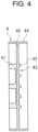
- Fig. 4 is a cross-sectional side view of end separator 4.
- Fig. 4 corresponds to a cross section including a stacking direction and a vertical direction of batteries.
- End separator 4 includes substrate 40 intersecting with the stacking direction of batteries 20, deformation allowing part 41, and air passage forming part 42.
- Deformation allowing part 41 is a part of end separator 4 in the stacking direction of batteries 20, and is formed of a resin material having larger deformation due to creep than other parts.
- Substrate 40 and air passage forming part 42 are made of a resin material having smaller deformation due to creep than deformation allowing part 41.
- Deformation allowing part 41 is formed in a trapezoidal shape so as to rise in the stacking direction from the central part of the surface of substrate 40 near end plate 11, and end surface 41a comes into contact with end plate 11.
- Air passage forming part 42 is formed of a plurality of strips protruding from the surface of substrate 40 near battery 20, and air passage 43 is formed between the strips.
- End separator 4 is in contact with end plate 11 at end surface 41a of the deformation allowing part 41, and is in contact with battery 20 at end surface 42a of air passage forming part 42.
- Battery 20 is fitted into wall 44 provided on a side part of substrate 40 and surrounding substrate 40.
- Deformation allowing part 41 has large creep deformation as described above, and is formed of a material different from substrate 40 and air passage forming part 42. Deformation allowing part 41 may be formed separately from substrate 40 and fixed to substrate 40 by adhesion or the like, or may be fixed to substrate 40 by integral molding with substrate 40 and air passage forming part 42.
- Fig. 5 is a schematic diagram for explaining a positional relationship in battery module 100 at an initial stage.
- Fig. 5 corresponds to a cross section including a stacking direction and a vertical direction of batteries.
- Each battery 20 does not expand at an initial stage after manufacturing, and a reaction force acting on each battery 20 in the stacking direction is small and is within a designed allowable value.
- Fig. 6 is a schematic diagram for explaining a state in which batteries 20 in battery module 100 bulge in the stacking direction due to aging degradation.
- Fig. 6 corresponds to a cross section including a stacking direction and a vertical direction of batteries.
- an internal electrode body, an electrolyte, and the like degrade over time, and bulge due to deposition or oxidation of a metal material, and a change appears in an outer shape.
- Each battery 20 is a prismatic battery and includes the outer covering can 21 having a flat rectangular-parallelepiped shape, and among the six surfaces of battery 20, the main surface having the largest area is deformed so as to expand.
- Deformation allowing part 41 is provided so as to be in contact with end plate 11, and can uniformly receive a load from end plate 11 formed of a highly rigid material such as metal on end surface 41a as a contact surface.
- Deformation allowing part 41 does not need to be in contact with the entire opposing surface of end plate 11, and is formed in a trapezoidal shape so as to rise in the stacking direction from the central part of the surface near substrate 40 on end plate 11, so that the contact area can be reduced and the generated stress can be increased.
- End separator 4 includes air passage forming part 42 on the side in contact with battery 20, so that air passage 43 for air cooling of battery 20 can be secured. Since air passage forming part 42 is formed of a material having a smaller creep deformation than deformation allowing part 41, it is possible to suppress a decrease in the flow passage area of air passage 43.
- Deformation allowing part 41 is integrally formed with substrate 40 and air passage forming part 42 by a manufacturing method such as two-color molding, so that the manufacturing cost can be reduced.
- deformation allowing part 41 is provided near end plate 11, but deformation allowing part 41 may be provided near battery 20. Even in this configuration, deformation allowing part 41 receives a load due to the expansion of battery 20 and is creep-deformed, whereby the reaction force generated in the stacking direction in battery module 100 can be reduced.
- the exemplary embodiment may be defined by the following items.
Landscapes
- Chemical & Material Sciences (AREA)
- Chemical Kinetics & Catalysis (AREA)
- Electrochemistry (AREA)
- General Chemical & Material Sciences (AREA)
- Engineering & Computer Science (AREA)
- Manufacturing & Machinery (AREA)
- Battery Mounting, Suspending (AREA)
Abstract
Description
- The present invention relates to a battery module.
- For example, as a power source for a vehicle or the like that requires a high output voltage, there has been known a battery module formed by electrically connecting a plurality of batteries to each other. In general, in each battery constituting a battery module, an internal electrode body, an electrolyte, and the like degrade over time, and bulge due to deposition or oxidation of a metal material, and a change appears in an outer shape. Regarding a battery module including such a battery,
PTL 1 discloses a battery module including a battery stack in which a plurality of batteries are stacked and an insulating sheet is interposed between the batteries, and end plates provided at both ends in the stacking direction of the battery stack. - PTL 1:
WO 2013/161655 A - When the dimension of each battery in the battery module in the stacking direction increases with aging, a load due to a dimensional variation of all the batteries is applied to the end plates at both ends of the battery stack, and a reaction force thereof is applied to each battery, which may cause a failure such as breakage of the battery.
- The present invention has been made in view of such circumstances, and an object of the present invention is to provide a technique for reducing a reaction force generated in a stacking direction in a battery module.
- A battery module according to an aspect of the present invention includes: a battery stack in which a plurality of batteries are stacked; an end plate provided outside a battery at an end in a stacking direction of the plurality of batteries; and an end separator provided between the battery at the end and the end plate, the end separator being disposed in a part in the stacking direction and including a deformation allowing part in which deformation due to creep is larger than deformation of other parts.
- According to the present invention, the safety of a battery module can be enhanced.
-
-
Fig. 1 is a perspective view illustrating an appearance of a battery module according to an exemplary embodiment. -
Fig. 2 is an exploded perspective view of a part of the battery module. -
Fig. 3 is a perspective view of an end separator as viewed from a battery side. -
Fig. 4 is a cross-sectional side view of the end separator. -
Fig. 5 is a schematic diagram for explaining a positional relationship in a battery module at an initial stage. -
Fig. 6 is a schematic diagram for explaining a state in which a battery in a battery module bulges in a stacking direction due to aged degradation. - Hereinafter, the present invention will be described based on a preferred exemplary embodiment with reference to the drawings. The exemplary embodiment is not intended to limit the invention but is an example, and all features described in the exemplary embodiment and combinations thereof are not necessarily essential to the invention. The same or equivalent constituent elements, members, and processing illustrated in the drawings are denoted by the same reference numerals, and a redundant description will be omitted as appropriate. The scale and the shape of each part illustrated in each figure are set for the sake of convenience in order to facilitate the understanding of the description and should not be interpreted in a limited manner unless otherwise specified. In cases where terms such as "first" and "second" are used in the present description or claims, these terms do not represent any order or importance but are intended to distinguish one configuration from another configuration, unless otherwise specified. From each of the drawings, some of members not important for describing the exemplary embodiments are omitted.
-
Fig. 1 is a perspective view illustrating an appearance ofbattery module 100 according to an exemplary embodiment, andFig. 2 is an exploded perspective view of a part ofbattery module 100.Battery module 100 includeshousing 1 having a rectangular-parallelepiped shape,battery stack 2,separator 3, andend separator 4. Inbattery module 100,end separator 4 is provided with a deformation allowing part in which the deformation due to the creep in the stacking direction is larger than the other parts, and the reaction force acting on the battery due to the creep of the deformation allowing part is reduced. -
Housing 1 includesend plate 11,side plate 12,base plate 13, andcover plate 14.End plates 11 are provided outsidebatteries 20 positioned at both ends ofbattery stack 2 in the stacking direction ofbatteries 20.Side plate 12sandwiches end plate 11 and covers a side surface ofbattery stack 2.Base plate 13 is configured by covering a bottom ofbattery stack 2.Cover plate 14 covers an upper surface ofbattery stack 2. -
Battery stack 2 is housed insidehousing 1.Battery stack 2 is formed by stacking a plurality ofbatteries 20 in one direction.Separator 3 formed of a resin material or the like in a sheet shape or a plate shape is provided between the batteries.Separator 3 electrically insulates eachbattery 20 ofbattery stack 2.Separator 3 may be considered to constitute a part ofbattery stack 2 becauseseparator 3 is incorporated into and integrated withbattery stack 2. - Each
battery 20 is a rechargeable secondary battery such as a lithium-ion battery, a nickel-metal-hydride battery, or a nickel-cadmium battery. Additionally, eachbattery 20 is a so-called prismatic battery, and has outer covering can 21 having a flat rectangular-parallelepiped shape. One surface of outer covering can 21 is provided with an opening having a substantially rectangular shape not illustrated, and an electrode body, an electrolyte, and the like are accommodated in outer covering can 21 through the opening.Sealing plate 21a that closes the opening of outer covering can 21 is disposed in the opening. -
Output terminal 22 of a positive electrode is disposed on sealingplate 21a at a position close to one end ofsealing plate 21a in a longitudinal direction, andoutput terminal 22 of a negative electrode is disposed onsealing plate 21a at a position close to the other end ofsealing plate 21a in the longitudinal direction. The pair ofoutput terminals 22 is electrically connected to the corresponding one of a positive electrode plate and a negative electrode plate, constituting the electrode assembly.Respective output terminals 22 are inserted into through-holes (not illustrated) formed insealing plate 21a. A seal member (not illustrated) having an insulating property is interposed betweenrespective output terminals 22 and respective through-holes. In the following description, for convenience,sealing plate 21a is an upper surface ofbattery 20, and a bottom surface of outer covering can 21 facingsealing plate 21a is a lower surface ofbattery 20. -
Battery 20 has two main surfaces that connect the upper surface and the lower surface ofbattery 20 to each other. The main surfaces are surfaces having the largest area out of the six surfaces ofbattery 20. The main surfaces are long side surfaces connected to the long sides of the upper surface and the long sides of the lower surface. Two remaining surfaces except for the upper surface, the lower surface, and the two main surfaces are referred to as the side surfaces ofbattery 20. These side surfaces are a pair of short side surfaces connected to the short sides of the upper surface and the short sides of the lower surface. These directions and positions are defined for the sake of convenience. Therefore, for example, the part defined as the upper surface in the present invention does not necessarily mean a part located above the part defined as the lower surface. - Valve 24 is disposed on sealing
plate 21a between the pair ofoutput terminals 22. Valve 24 is also referred to as a safety valve. Valve 24 is a mechanism for releasing a gas in eachbattery 20. Valve 24 is configured to release an internal gas by openingvalve 24 when an internal pressure of outer covering can 21 is increased to a predetermined value or more. For example,valve 24 includes: a thin part that is formed on a part ofsealing plate 21a and is thinner than other parts ofvalve 24; and a linear groove formed on a surface of the thin part. In this configuration, when an internal pressure of outer covering can 21 increases,valve 24 is opened by tearing the thin wall part with the groove as a tearing starting point. - The plurality of
batteries 20 are stacked at predetermined intervals with the main surfaces ofadjacent batteries 20 facing each other. Note that the term "stack" means that a plurality of members are arranged in any one direction. Thus, stackingbatteries 20 also includes arranging the plurality ofbatteries 20 horizontally. In the present exemplary embodiment,batteries 20 are stacked horizontally. Eachbattery 20 is disposed such thatoutput terminals 22 are directed in the same direction. In the present exemplary embodiment, eachbattery 20 is disposed such thatoutput terminals 22 are directed upward in the vertical direction. -
End separator 4 is provided betweenbatteries 20 positioned at an end ofbattery stack 2 in the stacking direction ofbatteries 20 andend plate 11.Fig. 3 is a perspective view ofend separator 4 as viewed frombattery 20 side, andFig. 4 is a cross-sectional side view ofend separator 4.Fig. 4 corresponds to a cross section including a stacking direction and a vertical direction of batteries. -
End separator 4 includessubstrate 40 intersecting with the stacking direction ofbatteries 20,deformation allowing part 41, and airpassage forming part 42.Deformation allowing part 41 is a part ofend separator 4 in the stacking direction ofbatteries 20, and is formed of a resin material having larger deformation due to creep than other parts.Substrate 40 and airpassage forming part 42 are made of a resin material having smaller deformation due to creep thandeformation allowing part 41. -
Deformation allowing part 41 is formed in a trapezoidal shape so as to rise in the stacking direction from the central part of the surface ofsubstrate 40 nearend plate 11, and endsurface 41a comes into contact withend plate 11. Airpassage forming part 42 is formed of a plurality of strips protruding from the surface ofsubstrate 40 nearbattery 20, andair passage 43 is formed between the strips. -
End separator 4 is in contact withend plate 11 atend surface 41a of thedeformation allowing part 41, and is in contact withbattery 20 at end surface 42a of airpassage forming part 42.Battery 20 is fitted intowall 44 provided on a side part ofsubstrate 40 and surroundingsubstrate 40.Deformation allowing part 41 has large creep deformation as described above, and is formed of a material different fromsubstrate 40 and airpassage forming part 42.Deformation allowing part 41 may be formed separately fromsubstrate 40 and fixed tosubstrate 40 by adhesion or the like, or may be fixed tosubstrate 40 by integral molding withsubstrate 40 and airpassage forming part 42. - Next, the operation of
battery module 100 will be described based on the generation of the reaction force due to the expansion ofbattery 20.Fig. 5 is a schematic diagram for explaining a positional relationship inbattery module 100 at an initial stage.Fig. 5 corresponds to a cross section including a stacking direction and a vertical direction of batteries. Eachbattery 20 does not expand at an initial stage after manufacturing, and a reaction force acting on eachbattery 20 in the stacking direction is small and is within a designed allowable value. -
Fig. 6 is a schematic diagram for explaining a state in whichbatteries 20 inbattery module 100 bulge in the stacking direction due to aging degradation.Fig. 6 corresponds to a cross section including a stacking direction and a vertical direction of batteries. As described above, in eachbattery 20, an internal electrode body, an electrolyte, and the like degrade over time, and bulge due to deposition or oxidation of a metal material, and a change appears in an outer shape. Eachbattery 20 is a prismatic battery and includes the outer covering can 21 having a flat rectangular-parallelepiped shape, and among the six surfaces ofbattery 20, the main surface having the largest area is deformed so as to expand. - The deformation in the stacking direction caused by the expansion of each
battery 20 inbattery module 100 is absorbed when the dimension ofdeformation allowing part 41 ofend separator 4 in the stacking direction decreases due to the creep deformation. Therefore,battery module 100 can reduce the reaction force generated in the stacking direction. -
Deformation allowing part 41 is provided so as to be in contact withend plate 11, and can uniformly receive a load fromend plate 11 formed of a highly rigid material such as metal onend surface 41a as a contact surface. -
Deformation allowing part 41 does not need to be in contact with the entire opposing surface ofend plate 11, and is formed in a trapezoidal shape so as to rise in the stacking direction from the central part of the surface nearsubstrate 40 onend plate 11, so that the contact area can be reduced and the generated stress can be increased. -
End separator 4 includes airpassage forming part 42 on the side in contact withbattery 20, so thatair passage 43 for air cooling ofbattery 20 can be secured. Since airpassage forming part 42 is formed of a material having a smaller creep deformation thandeformation allowing part 41, it is possible to suppress a decrease in the flow passage area ofair passage 43. -
Deformation allowing part 41 is integrally formed withsubstrate 40 and airpassage forming part 42 by a manufacturing method such as two-color molding, so that the manufacturing cost can be reduced. - In the above-described exemplary embodiment,
deformation allowing part 41 is provided nearend plate 11, butdeformation allowing part 41 may be provided nearbattery 20. Even in this configuration,deformation allowing part 41 receives a load due to the expansion ofbattery 20 and is creep-deformed, whereby the reaction force generated in the stacking direction inbattery module 100 can be reduced. - The present invention has been described based on the exemplary embodiment of the present invention. As a person skilled in the art understands, the exemplary embodiment is exemplified, and the exemplary embodiment is variously varied and modified within a scope of claims of the present invention. Further, such variations and modified examples fall within the scope of the claims of the present invention. Therefore, it should be understood that the description and the drawings herein are not limitative, but are illustrative.
- The exemplary embodiment may be defined by the following items.
- [Item 1]
Battery module (100) including: battery stack (2) in which a plurality of batteries (20) are stacked; end plate (11) provided outside battery (20) at an end in a stacking direction of the plurality of batteries (20); and end separator (4) provided between battery (20) at the end and end plate (11), the end separator (4) being disposed in a part in the stacking direction and including deformation allowing part (41) in which deformation due to creep is larger than deformation of other parts. Thus, battery module (100) can reduce the reaction force generated in the stacking direction. - [Item 2]
Battery module (100) according toItem 1, in which deformation allowing part (41) is disposed in a part of the end separator (4) in contact with end plate (11). Consequently, deformation allowing part (41) of battery module (100) can uniformly receive a load from end plate (11) made of a highly rigid material such as metal on the contact surface. - [Item 3]
Battery module (100) according toItem - [Item 4]
Battery module (100) according to any one ofItems 1 to 3, in which air passage (43) is disposed between battery (20) at the end and end separator (4). Thus, battery module (100) can secure air passage (43) for air cooling of battery (20). - [Item 5]
Battery module (100) according to any one ofItems 1 to 4, in which deformation allowing part (41) and other parts are integrally disposed in end separator (4). Thus, the manufacturing cost of battery module (100) can be reduced. -
- 11
- end plate
- 2
- battery stack
- 20
- battery
- 4
- end separator
- 41
- deformation allowing part
- 43
- air passage
- 100
- battery module
Claims (5)
- A battery module comprising:a battery stack including a plurality of batteries stacked;an end plate provided outside a battery at an end in a stacking direction among the plurality of batteries; andan end separator provided between the battery at the end and the end plate, the end separator including a deformation allowing part disposed in a part of the end separator in the stacking direction, including deformation due to creep is larger than deformation of other parts of the end separator.
- The battery module according to Claim 1, wherein the deformation allowing part is a part of the end separator, the part being in contact with the end plate.
- The battery module according to Claim 1 or 2, wherein the deformation allowing part is disposed to rise in a trapezoidal shape from a surface of the end separator, the surface intersecting the stacking direction.
- The battery module according to any one of Claims 1 to 3, wherein an air passage is disposed between the battery at the end and the end separator.
- The battery module according to any one of Claims 1 to 4, wherein the deformation allowing part and the other parts are integrally disposed in the end separator.
Applications Claiming Priority (2)
| Application Number | Priority Date | Filing Date | Title |
|---|---|---|---|
| JP2020064242 | 2020-03-31 | ||
| PCT/JP2021/001783 WO2021199591A1 (en) | 2020-03-31 | 2021-01-20 | Battery module |
Publications (2)
| Publication Number | Publication Date |
|---|---|
| EP4131601A1 true EP4131601A1 (en) | 2023-02-08 |
| EP4131601A4 EP4131601A4 (en) | 2024-04-17 |
Family
ID=77929933
Family Applications (1)
| Application Number | Title | Priority Date | Filing Date |
|---|---|---|---|
| EP21780088.7A Pending EP4131601A4 (en) | 2020-03-31 | 2021-01-20 | Battery module |
Country Status (5)
| Country | Link |
|---|---|
| US (1) | US12489168B2 (en) |
| EP (1) | EP4131601A4 (en) |
| JP (1) | JP7654638B2 (en) |
| CN (1) | CN114930625B (en) |
| WO (1) | WO2021199591A1 (en) |
Family Cites Families (15)
| Publication number | Priority date | Publication date | Assignee | Title |
|---|---|---|---|---|
| JPH0845535A (en) * | 1994-08-01 | 1996-02-16 | Ishikawajima Harima Heavy Ind Co Ltd | Fuel cell tightening device |
| JPH09100511A (en) * | 1995-10-09 | 1997-04-15 | Tokai Rubber Ind Ltd | Rubber support and bridge support structure using the same |
| JPH09100510A (en) * | 1995-10-09 | 1997-04-15 | Tokai Rubber Ind Ltd | Bridge construction method and rubber support used for it |
| JP4127985B2 (en) * | 2001-07-23 | 2008-07-30 | 松下電器産業株式会社 | Battery pack |
| JP5122898B2 (en) * | 2007-09-26 | 2013-01-16 | トヨタ自動車株式会社 | Power storage module |
| JP2015133169A (en) | 2012-04-27 | 2015-07-23 | 三洋電機株式会社 | Power supply device, and vehicle and power storage device provided with the same |
| JP6016026B2 (en) * | 2013-02-15 | 2016-10-26 | トヨタ自動車株式会社 | Battery pack and battery module |
| JP6379692B2 (en) * | 2014-06-03 | 2018-08-29 | 株式会社豊田自動織機 | Battery module |
| WO2016157267A1 (en) * | 2015-03-31 | 2016-10-06 | 三洋電機株式会社 | Power supply device and vehicle provided with power supply device |
| KR102308635B1 (en) * | 2015-04-17 | 2021-10-05 | 삼성에스디아이 주식회사 | Battery module |
| CN107851757B (en) * | 2015-07-30 | 2020-11-13 | 三洋电机株式会社 | Power supply unit, power supply system including the same, and separator for battery unit |
| WO2019058902A1 (en) | 2017-09-22 | 2019-03-28 | 日産自動車株式会社 | Spring member, fuel cell unit, fuel cell stack, and method for manufacturing fuel cell stack |
| JP7174923B2 (en) | 2018-01-17 | 2022-11-18 | パナソニックIpマネジメント株式会社 | power storage device |
| JP7181740B2 (en) | 2018-09-12 | 2022-12-01 | 小島プレス工業株式会社 | battery module |
| JP2021193639A (en) | 2018-09-19 | 2021-12-23 | 三洋電機株式会社 | Battery module |
-
2021
- 2021-01-20 WO PCT/JP2021/001783 patent/WO2021199591A1/en not_active Ceased
- 2021-01-20 CN CN202180008363.8A patent/CN114930625B/en active Active
- 2021-01-20 US US17/906,479 patent/US12489168B2/en active Active
- 2021-01-20 EP EP21780088.7A patent/EP4131601A4/en active Pending
- 2021-01-20 JP JP2022511559A patent/JP7654638B2/en active Active
Also Published As
| Publication number | Publication date |
|---|---|
| EP4131601A4 (en) | 2024-04-17 |
| CN114930625A (en) | 2022-08-19 |
| US20230135184A1 (en) | 2023-05-04 |
| WO2021199591A1 (en) | 2021-10-07 |
| JP7654638B2 (en) | 2025-04-01 |
| US12489168B2 (en) | 2025-12-02 |
| JPWO2021199591A1 (en) | 2021-10-07 |
| CN114930625B (en) | 2024-11-26 |
Similar Documents
| Publication | Publication Date | Title |
|---|---|---|
| EP3944359B1 (en) | Battery module | |
| EP3944356B1 (en) | Battery module | |
| US20130095356A1 (en) | Cell module | |
| KR20190040403A (en) | Cylindrical secondary battery module and production method for the same | |
| US20010041284A1 (en) | Closure assembly for sealed batteries | |
| CN110021725B (en) | Battery | |
| EP3944358A1 (en) | Battery module | |
| JP5592291B2 (en) | Sealed battery and safety valve | |
| JP2006012831A (en) | Secondary battery, secondary battery cap assembly, and secondary battery safety valve mounting method | |
| CN104167515B (en) | Cover board and battery | |
| JP7307069B2 (en) | Fixing structure of battery module | |
| US12489168B2 (en) | Battery module | |
| CN115588812A (en) | Power storage module and power storage pack | |
| US20230170573A1 (en) | Battery module | |
| US12531265B2 (en) | Battery module | |
| JP2025540829A (en) | Electrical connection assembly, battery assembly, and vehicle | |
| JP2018006249A (en) | Battery pack | |
| JP7630097B2 (en) | Energy Storage Module | |
| EP4564547A1 (en) | Battery cell and battery module including the same | |
| EP4407759A1 (en) | Casing of a battery cell | |
| EP4708528A1 (en) | Battery cell and battery module including the same | |
| CN120810129A (en) | Battery system and electric vehicle including the same | |
| KR20060086124A (en) | Secondary Battery and Safety Valve Installation Method | |
| JP2017174655A (en) | Battery pack and method of manufacturing battery pack | |
| KR20260052401A (en) | Battery module |
Legal Events
| Date | Code | Title | Description |
|---|---|---|---|
| STAA | Information on the status of an ep patent application or granted ep patent |
Free format text: STATUS: THE INTERNATIONAL PUBLICATION HAS BEEN MADE |
|
| PUAI | Public reference made under article 153(3) epc to a published international application that has entered the european phase |
Free format text: ORIGINAL CODE: 0009012 |
|
| STAA | Information on the status of an ep patent application or granted ep patent |
Free format text: STATUS: REQUEST FOR EXAMINATION WAS MADE |
|
| 17P | Request for examination filed |
Effective date: 20221017 |
|
| AK | Designated contracting states |
Kind code of ref document: A1 Designated state(s): AL AT BE BG CH CY CZ DE DK EE ES FI FR GB GR HR HU IE IS IT LI LT LU LV MC MK MT NL NO PL PT RO RS SE SI SK SM TR |
|
| DAV | Request for validation of the european patent (deleted) | ||
| DAX | Request for extension of the european patent (deleted) | ||
| REG | Reference to a national code |
Ref country code: DE Ref legal event code: R079 Free format text: PREVIOUS MAIN CLASS: H01M0050200000 Ipc: H01M0050293000 |
|
| A4 | Supplementary search report drawn up and despatched |
Effective date: 20240320 |
|
| RIC1 | Information provided on ipc code assigned before grant |
Ipc: H01M 10/6561 20140101ALI20240314BHEP Ipc: H01M 10/6556 20140101ALI20240314BHEP Ipc: H01M 10/647 20140101ALI20240314BHEP Ipc: H01M 10/613 20140101ALI20240314BHEP Ipc: H01M 50/209 20210101ALI20240314BHEP Ipc: H01M 50/291 20210101ALI20240314BHEP Ipc: H01M 50/293 20210101AFI20240314BHEP |
|
| STAA | Information on the status of an ep patent application or granted ep patent |
Free format text: STATUS: EXAMINATION IS IN PROGRESS |
|
| 17Q | First examination report despatched |
Effective date: 20251203 |