EP4131579A1 - Batteriemodul und batteriepack damit - Google Patents
Batteriemodul und batteriepack damit Download PDFInfo
- Publication number
- EP4131579A1 EP4131579A1 EP22759980.0A EP22759980A EP4131579A1 EP 4131579 A1 EP4131579 A1 EP 4131579A1 EP 22759980 A EP22759980 A EP 22759980A EP 4131579 A1 EP4131579 A1 EP 4131579A1
- Authority
- EP
- European Patent Office
- Prior art keywords
- battery
- busbar
- battery module
- frame
- module
- Prior art date
- Legal status (The legal status is an assumption and is not a legal conclusion. Google has not performed a legal analysis and makes no representation as to the accuracy of the status listed.)
- Granted
Links
Images


Classifications
-
- H—ELECTRICITY
- H01—ELECTRIC ELEMENTS
- H01M—PROCESSES OR MEANS, e.g. BATTERIES, FOR THE DIRECT CONVERSION OF CHEMICAL ENERGY INTO ELECTRICAL ENERGY
- H01M50/00—Constructional details or processes of manufacture of the non-active parts of electrochemical cells other than fuel cells, e.g. hybrid cells
- H01M50/20—Mountings; Secondary casings or frames; Racks, modules or packs; Suspension devices; Shock absorbers; Transport or carrying devices; Holders
- H01M50/204—Racks, modules or packs for multiple batteries or multiple cells
- H01M50/207—Racks, modules or packs for multiple batteries or multiple cells characterised by their shape
- H01M50/209—Racks, modules or packs for multiple batteries or multiple cells characterised by their shape adapted for prismatic or rectangular cells
-
- H—ELECTRICITY
- H01—ELECTRIC ELEMENTS
- H01M—PROCESSES OR MEANS, e.g. BATTERIES, FOR THE DIRECT CONVERSION OF CHEMICAL ENERGY INTO ELECTRICAL ENERGY
- H01M10/00—Secondary cells; Manufacture thereof
- H01M10/60—Heating or cooling; Temperature control
- H01M10/61—Types of temperature control
- H01M10/613—Cooling or keeping cold
-
- H—ELECTRICITY
- H01—ELECTRIC ELEMENTS
- H01M—PROCESSES OR MEANS, e.g. BATTERIES, FOR THE DIRECT CONVERSION OF CHEMICAL ENERGY INTO ELECTRICAL ENERGY
- H01M10/00—Secondary cells; Manufacture thereof
- H01M10/60—Heating or cooling; Temperature control
- H01M10/65—Means for temperature control structurally associated with the cells
- H01M10/653—Means for temperature control structurally associated with the cells characterised by electrically insulating or thermally conductive materials
-
- H—ELECTRICITY
- H01—ELECTRIC ELEMENTS
- H01M—PROCESSES OR MEANS, e.g. BATTERIES, FOR THE DIRECT CONVERSION OF CHEMICAL ENERGY INTO ELECTRICAL ENERGY
- H01M10/00—Secondary cells; Manufacture thereof
- H01M10/60—Heating or cooling; Temperature control
- H01M10/65—Means for temperature control structurally associated with the cells
- H01M10/655—Solid structures for heat exchange or heat conduction
- H01M10/6551—Surfaces specially adapted for heat dissipation or radiation, e.g. fins or coatings
-
- H—ELECTRICITY
- H01—ELECTRIC ELEMENTS
- H01M—PROCESSES OR MEANS, e.g. BATTERIES, FOR THE DIRECT CONVERSION OF CHEMICAL ENERGY INTO ELECTRICAL ENERGY
- H01M50/00—Constructional details or processes of manufacture of the non-active parts of electrochemical cells other than fuel cells, e.g. hybrid cells
- H01M50/20—Mountings; Secondary casings or frames; Racks, modules or packs; Suspension devices; Shock absorbers; Transport or carrying devices; Holders
- H01M50/204—Racks, modules or packs for multiple batteries or multiple cells
- H01M50/207—Racks, modules or packs for multiple batteries or multiple cells characterised by their shape
- H01M50/211—Racks, modules or packs for multiple batteries or multiple cells characterised by their shape adapted for pouch cells
-
- H—ELECTRICITY
- H01—ELECTRIC ELEMENTS
- H01M—PROCESSES OR MEANS, e.g. BATTERIES, FOR THE DIRECT CONVERSION OF CHEMICAL ENERGY INTO ELECTRICAL ENERGY
- H01M50/00—Constructional details or processes of manufacture of the non-active parts of electrochemical cells other than fuel cells, e.g. hybrid cells
- H01M50/20—Mountings; Secondary casings or frames; Racks, modules or packs; Suspension devices; Shock absorbers; Transport or carrying devices; Holders
- H01M50/262—Mountings; Secondary casings or frames; Racks, modules or packs; Suspension devices; Shock absorbers; Transport or carrying devices; Holders with fastening means, e.g. locks
- H01M50/264—Mountings; Secondary casings or frames; Racks, modules or packs; Suspension devices; Shock absorbers; Transport or carrying devices; Holders with fastening means, e.g. locks for cells or batteries, e.g. straps, tie rods or peripheral frames
-
- H—ELECTRICITY
- H01—ELECTRIC ELEMENTS
- H01M—PROCESSES OR MEANS, e.g. BATTERIES, FOR THE DIRECT CONVERSION OF CHEMICAL ENERGY INTO ELECTRICAL ENERGY
- H01M50/00—Constructional details or processes of manufacture of the non-active parts of electrochemical cells other than fuel cells, e.g. hybrid cells
- H01M50/40—Separators; Membranes; Diaphragms; Spacing elements inside cells
- H01M50/409—Separators, membranes or diaphragms characterised by the material
- H01M50/411—Organic material
- H01M50/414—Synthetic resins, e.g. thermoplastics or thermosetting resins
-
- H—ELECTRICITY
- H01—ELECTRIC ELEMENTS
- H01M—PROCESSES OR MEANS, e.g. BATTERIES, FOR THE DIRECT CONVERSION OF CHEMICAL ENERGY INTO ELECTRICAL ENERGY
- H01M50/00—Constructional details or processes of manufacture of the non-active parts of electrochemical cells other than fuel cells, e.g. hybrid cells
- H01M50/50—Current conducting connections for cells or batteries
- H01M50/502—Interconnectors for connecting terminals of adjacent batteries; Interconnectors for connecting cells outside a battery casing
- H01M50/507—Interconnectors for connecting terminals of adjacent batteries; Interconnectors for connecting cells outside a battery casing comprising an arrangement of two or more busbars within a container structure, e.g. busbar modules
-
- H—ELECTRICITY
- H01—ELECTRIC ELEMENTS
- H01M—PROCESSES OR MEANS, e.g. BATTERIES, FOR THE DIRECT CONVERSION OF CHEMICAL ENERGY INTO ELECTRICAL ENERGY
- H01M10/00—Secondary cells; Manufacture thereof
- H01M10/60—Heating or cooling; Temperature control
- H01M10/64—Heating or cooling; Temperature control characterised by the shape of the cells
- H01M10/647—Prismatic or flat cells, e.g. pouch cells
-
- H—ELECTRICITY
- H01—ELECTRIC ELEMENTS
- H01M—PROCESSES OR MEANS, e.g. BATTERIES, FOR THE DIRECT CONVERSION OF CHEMICAL ENERGY INTO ELECTRICAL ENERGY
- H01M10/00—Secondary cells; Manufacture thereof
- H01M10/60—Heating or cooling; Temperature control
- H01M10/65—Means for temperature control structurally associated with the cells
- H01M10/655—Solid structures for heat exchange or heat conduction
- H01M10/6553—Terminals or leads
-
- H—ELECTRICITY
- H01—ELECTRIC ELEMENTS
- H01M—PROCESSES OR MEANS, e.g. BATTERIES, FOR THE DIRECT CONVERSION OF CHEMICAL ENERGY INTO ELECTRICAL ENERGY
- H01M2220/00—Batteries for particular applications
- H01M2220/30—Batteries in portable systems, e.g. mobile phone, laptop
-
- Y—GENERAL TAGGING OF NEW TECHNOLOGICAL DEVELOPMENTS; GENERAL TAGGING OF CROSS-SECTIONAL TECHNOLOGIES SPANNING OVER SEVERAL SECTIONS OF THE IPC; TECHNICAL SUBJECTS COVERED BY FORMER USPC CROSS-REFERENCE ART COLLECTIONS [XRACs] AND DIGESTS
- Y02—TECHNOLOGIES OR APPLICATIONS FOR MITIGATION OR ADAPTATION AGAINST CLIMATE CHANGE
- Y02E—REDUCTION OF GREENHOUSE GAS [GHG] EMISSIONS, RELATED TO ENERGY GENERATION, TRANSMISSION OR DISTRIBUTION
- Y02E60/00—Enabling technologies; Technologies with a potential or indirect contribution to GHG emissions mitigation
- Y02E60/10—Energy storage using batteries
Definitions
- the present disclosure relates to a battery module and a battery pack including the same, and more particularly, to a battery module having novel cooling structure and a battery pack including the same.
- a secondary battery has attracted considerable attention as an energy source for power-driven devices, such as an electric bicycle, an electric vehicle, and a hybrid electric vehicle, as well as an energy source for mobile devices, such as a mobile phone, a digital camera, a laptop computer and a wearable device.
- Small-sized mobile devices use one or several battery cells for each device, whereas middle or large-sized devices such as vehicles require high power and large capacity. Therefore, a middle or large-sized battery module having a plurality of battery cells electrically connected to one another is used.
- the middle or large-sized battery module is preferably manufactured so as to have as small a size and weight as possible, a prismatic battery, a pouch-shaped battery or the like, which can be stacked with high integration and has a small weight relative to capacity, is mainly used as a battery cell of the middle or large-sized battery module.
- a battery module has a structure in which a plurality of cell assemblies including a plurality of unit battery cells are connected in series in order to obtain high output.
- the battery cell includes positive electrode and negative electrode current collectors, a separator, an active material, an electrolyte solution, and the like, and thus can be repeatedly charged and discharged by an electrochemical reaction between components.
- a method of first configuring a battery module composed of at least one battery cell and then adding other components to at least one battery module to configure a battery pack is common.
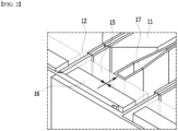
- Fig. 1 shows a part of a perspective view according to a conventional battery module.
- Fig. 2 is an enlarged view showing a part of a cross-sectional view taken along the xy plane with reference to the cutting line A-A' of Fig. 1 .
- the conventional battery module includes a battery cell assembly consisting of a plurality of battery cells 11 stacked on each other, and a busbar assembly that electrically connects the electrode leads 12 of the plurality of battery cells 11 to each other, a module frame 13 that wraps the battery cell assembly, and an external frame 14 that covers a busbar assembly.
- the busbar assembly includes a busbar frame 15 having lead slots that allow the discrete passage of the electrode leads 12 of each battery cell 11, and busbar slots mounted on the busbar frame 15 and provided so as to correspond to the number of lead slots, and further includes a busbar 16 that is connected to the electrode leads passing through the busbar slots by welding, etc.
- a cooling fin 17 may be arranged between the battery cells 11 of the battery cell assembly.
- the busbar 16 is separated from the cooling fin 17 by the busbar frame 15, so that heat generated in the busbar 16 cannot be directly transferred to the cooling fin 17. Instead, the heat generated in the busbar 16 is transferred via the electrode leads 12, transferred to the cooling fin 17, and then transferred via a thermal conductive resin layer formed on the bottom part of the battery cell 11 and the module frame 13.
- a battery module comprising: a battery cell stack in which a plurality of battery cells are stacked, a module frame that wraps the battery cell stack, a busbar frame that covers a portion of the battery cell stack exposed from the module frame, a busbar that is connected to an electrode lead protruding from the battery cell stack via a first slot formed in the busbar frame, and a cooling fin that is located between battery cells adj acent to each other among the plurality of battery cells, wherein the busbar is connected to the cooling fin.
- the battery module may further include a heat transfer member located between the busbar and the cooling fin.
- the busbar frame may further include a second slot, and the heat transfer member may be formed adjacent to the second slot to come into contact with the busbar.
- the cooling fin may be inserted into the second slot to come into contact with the heat transfer member.
- the heat transfer member may be formed of a material having electrical insulating properties and thermal conductivity.
- the heat transfer member may be surface-joined with the busbar.
- the cooling fin may be surface-joined with the heat transfer member.
- the battery module may further include a thermal conductive resin layer located on the bottom part of the module frame, wherein the cooling fin may be contact with the thermal conductive resin layer, and the heat generated from the busbar may be sequentially transferred to the heat transfer member, the cooling fin, and the thermal conductive resin layer.
- the module frame of the battery module may include a structure that is opened in the upper and lower surfaces and wraps all side surface parts of the battery cell stack.
- the battery module may further include a cooling plate located at the lower end of the thermal conductive resin layer, wherein the thermal conductive resin layer may come into contact with the cooling plate, and the heat transferred to the thermal conductive resin layer may be transferred to the cooling plate.
- a battery pack comprising the above-mentioned battery module.
- the problem of heat generation of the busbar in a high current and fast charging environment can be solved by a novel type of busbar cooling structure. Additionally, the stability of the battery module can be improved by solving the heat generation problem.
- planar when referred to as “planar”, it means when a target portion is viewed from the upper side, and when referred to as “cross-sectional”, it means when a target portion is viewed from the side of a cross section cut vertically.
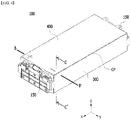
- Fig. 3 is an exploded perspective view of a battery module according to an embodiment of the present disclosure.
- Fig. 4 is a perspective view showing a state in which the components of the battery module of Fig. 3 are combined.
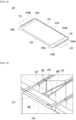
- Fig. 5 is a perspective view showing one battery cell included in the battery cell stack of Fig. 3 .
- the battery module 100 may include a battery cell stack 120 in which a plurality of battery cells 110 are stacked, a module frame that wraps the battery cell stack 120, an upper plate 400 that covers the upper part of the battery cell stack 120, end plates 150 that are respectively located on the front and rear surfaces of the battery cell stack 120, and a busbar frame 130 that is located between the battery cell stack 120 and the end plate 150.
- the module frame may include a U-shaped frame 300 of which an upper surface, a front surface and a rear surface are opened.
- the battery module 100 includes a thermal conductive resin layer 310 located between the U-shaped frame 300 and the battery cell stack 120.
- the thermal conductive resin layer 310 is a kind of heat dissipation layer, and may be formed by applying a material having a heat dissipation function.
- the end plate 150 may be formed of a metal material.
- the U-shaped frame 300 When opened both sides of the U-shaped frame 300 are referred to as a first side and a second side, respectively, the U-shaped frame 300 has a plate-shaped structure that is bent so as to continuously warp the front, lower and rear surfaces adjacent to each other among the remaining outer surfaces excluding surfaces of the battery cell stack 120 corresponding to the first side and the second side.
- the upper surface corresponding to the lower surface of the U-shaped frame 300 is opened.
- the upper plate 400 has a single plate-shaped structure that covers the remaining upper surface excluding the front, lower and rear surfaces which are wrapped by the U-shaped frame 300.
- the U-shaped frame 300 and the upper plate 400 can be coupled by welding or the like in a state in which the corresponding edge areas are in contact with each other, thereby forming a structure wrapping the battery cell stack 120. That is, the U-shaped frame 300 and the upper plate 400 can have a coupling part CP formed by a coupling method such as welding at an edge area corresponding to each other.
- the battery cell stack 120 includes a plurality of battery cells 110 stacked in one direction, and the plurality of battery cells 110 may be stacked in the y-axis direction as shown in Fig. 3 .
- a direction in which the plurality of battery cells 110 are stacked may be the same as a direction in which two side surface parts of the U-shaped frame 300 face each other.
- the battery cell 110 is preferably a pouch type battery cell.
- the battery cell 110 according to the present embodiment may have a structure in which the two electrode leads 111 and 112 protrude from one end part 114a and the other end part 114b of the battery main body 113 toward mutually opposite directions, respectively.
- the battery cell 110 can be manufactured by joining both end parts 114a and 114b of the cell case 114 and both side surfaces 114c connecting them in a state in which an electrode assembly (not shown) is housed in the cell case 114.
- the battery cell 110 has a total of three sealing parts 114sa, 114sb and 114sc, wherein the sealing parts 114sa, 114sb and 114sc have a structure that is sealed by a method such as heat fusion, and the remaining other side part may be formed of a connection part 115.
- Between both end parts 114a and 114b of the battery case 114 is defined as a longitudinal direction of the battery cell 110, and between the one side surface 114c and the connection part 115 that connect both end parts 114a and 114b of the battery case 114 is defined as a width direction of the battery cell 110.
- connection part 115 is a region that extends long along one edge of the battery cell 110, and a protrusion part 110p of the battery cell 110 may be formed at an end part of the connection part 115.
- the protrusion part 110p may be formed on at least one of both end parts of the connection part 115 and may protrude in a direction perpendicular to the direction in which the connection part 115 extends.
- the protrusion part 110p may be located between one of the sealing parts 114sa and 114sb of both end parts 114a and 114b of the battery case 114, and the connection part 115.
- the cell case 114 is generally formed of a laminated structure of a resin layer/metallic thin film layer/resin layer.
- a surface of the battery case formed of an O(oriented)-nylon layer tends to slide easily by an external impact when a plurality of battery cells are stacked in order to form a medium- or large-sized battery module. Therefore, in order to prevent this sliding and maintain a stable stacked structure of the battery cells, an adhesive member, for example, a sticky adhesive such as a double-sided tape or a chemical adhesive coupled by a chemical reaction upon adhesion, can be attached to the surface of the battery case to form the battery cell stack 120.
- a sticky adhesive such as a double-sided tape or a chemical adhesive coupled by a chemical reaction upon adhesion
- the battery cell stack 120 may be stacked in a y-axis direction and housed into the U-shaped frame 300 in a z-axis direction.
- the battery cells are formed as cartridge-shaped components so that fixing between the battery cells leads to assembling by the battery module frame.
- the cooling due to the presence of the cartridge-shaped components, there is almost no cooling action or the cooling may be proceeded in a surface direction of the battery cells, whereby the cooling does not well perform toward a height direction of the battery module.
- the U-shaped frame 300 includes a bottom part and two side surface parts facing each other connected by the bottom part.
- a thermal conductive resin is applied to the bottom part of the U-shaped frame 300, and the thermal conductive resin can be cured to form a thermal conductive resin layer 310.
- the thermal conductive resin layer 310 is located between the bottom part of the U-shaped frame 300 and the battery cell stack, and can serve to transfer heat generated in the battery cell 110 to the bottom of the battery module 100 and fix the battery cell stack 120.
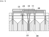
- Fig. 6 is an enlarged view showing a part of a cross-sectional view taken along the xy plane with reference to the cutting line B-B' of Fig. 4 .
- Fig. 7 shows the upper cross-section in Fig. 6 as viewed from above.
- Fig. 8 is an enlarged view showing a part of a cross-sectional view taken along the xz plane with reference to the cutting line C-C' of Fig. 4 .
- the conventional battery module does not have a direct cooling path for the busbar, and thus, heat generated by the busbar was emitted only by a path connecting to the busbar, electrode leads, battery cells, cooling fins, and thermal conductive resin layer.
- a cooling structure capable of minimizing the temperature rise of the busbar was needed.
- the battery module 100 includes a busbar frame 130 that covers a portion of the battery cell stack 120 exposed from the module frame 300, a busbar 170 that is connected to the electrode lead 111 protruding from the battery cell stack via a first slot 131 formed in the busbar frame 130, and a cooling fin 200 that is located between battery cells 110 adjacent to each other among the plurality of battery cells 110.
- the busbar 170 is connected to the cooling fin 200.
- the battery module 100 according to the present embodiment may further include a heat transfer member 180 located between the busbar 170 and the cooling fin 200. In a modified embodiment, the heat transfer member 180 may be omitted, and the cooling fin 200 may be in direct contact with the busbar 170.
- the busbar frame 130 may further include a second slot 132.
- the heat transfer member 180 may be formed so as to be adjacent to the second slot 132 of the busbar frame 130 to come into contact with the busbar 170.
- the cooling fin 200 may be inserted into the second slot 132 to come into contact with the heat transfer member 180. Further, the cooling fin 200 may further come into contact with the second slot 132 and the busbar frame 130. Successive heat transfer of the busbar 170, heat transfer member 180 and cooling fin 200, or successive heat transfer of the busbar 170, heat transfer member 180, cooling fin 200 and busbar frame 130 can be made through the contacts.
- the heat transfer member 180 may be formed of a material having electrical insulation properties and thermal conductivity.
- the heat transfer member 180 may include one of a heat transfer pad and a thermal conductive resin layer. Therefore, the heat transfer member 180 may enable heat conduction while maintaining insulation properties between the busbar 170 and the cooling fin 200.
- the heat transfer member 180 may be surface-joined with the busbar 170.
- the cooling fin 200 may be surface-joined with the heat transfer member 180. Therefore, heat in the busbar 170 may be transferred to the cooling fin 200 by the busbar 170, the heat transfer member 180, and the cooling fins 200 that are surface-joined as described above.
- the battery module according to the present embodiment may further include a thermal conductive resin layer 310 that is located on the bottom part of the module frame, particularly the U-shaped frame 300 of the module frame.
- the cooling fins 200 may come into contact with the thermal conductive resin layer 310.
- a cooling plate 700 as a pack component or a cooling plate 700 integrally formed with the battery module may be formed under the bottom part of the U-shaped frame 300 included in the battery module according to the present embodiment.
- the heat transferred to the cooling fin 200 is transferred to the thermal conductive resin layer 310, transferred from the thermal conductive resin layer 310 to the cooling plate 700 to be discharged.
- the heat generated from the busbar 170 may be sequentially transferred to the heat transfer member 180, the cooling fins 200, the thermal conductive resin layer 310, and the cooling plate 700 to be discharged.
- the sequential delivery and release structure as described above heat from the busbar generated in a high current situation such as rapid charging can be effectively dissipated, and the stability of the battery module can be secured.
- the cooling fin 200 can not only directly cool the busbar 170, but also transfer and cool the heat generated in the battery cell 110 to the thermal conductive resin layer 310 and the cooling plate 700, and thus, dual cooling can be made. Further, the busbar 170 is thermally connected to the battery cell 110 having high specific heat and thermal capacity via the cooling fin 200, so that not only it slows down the temperature rise rate of the busbar 170, but also the resistance can be lowered by keeping the temperature of the busbar 170 rather high when the outside air temperature is low. Thereby, the energy efficiency can be increased.
- Fig. 9 is an exploded perspective view showing a part of a battery module according to another embodiment of the present disclosure. Since contents overlapping with the contents of the above-mentioned battery module exist herein, only the contents different from those concerning the above-mentioned will be described.
- the module frame of the present disclosure may be a wrapping frame 305 that is opened in the upper and lower surfaces, and wraps all side surface parts of the battery cell stack 120. Since the wrapping frame 305 is opened in both the upper and lower surfaces, the thermal conductive resin layer 310 may be formed at a position corresponding to the lower surface of the wrapping frame 305.
- the battery module 1000 of the present disclosure includes a wrapping frame 305, whereby it can maximize the contact between the battery cell stack 120 and the thermal conductive resin layer 310 and between the cooling fins 200 and the thermal conductive resin layer 310 to maximize heat transfer and heat dissipation.
- the battery module 1000 of the present disclosure may further include a cooling plate 700 that is located at the lower end of the thermal conductive resin layer 310.
- the thermal conductive resin layer 310 may further come into contact with the cooling plate to conduct heat transfer. Accordingly, the effect that heat transfer is maximized can be achieved.
- the above-mentioned battery module can be included in the battery pack.
- the battery pack may have a structure in which one or more of the battery modules according to the embodiment of the present disclosure are gathered, and packed together with a battery management system (BMS) and a cooling device that control and manage battery's temperature, voltage, etc.
- BMS battery management system
- the above-mentioned battery pack can be applied to various devices.
- a device may be applied to a vehicle means such as an electric bicycle, an electric vehicle, or a hybrid vehicle, but the present disclosure is not limited thereto, and is applicable to various devices that can use a battery module, which also falls under the scope of the present disclosure.
Landscapes
- Chemical & Material Sciences (AREA)
- Chemical Kinetics & Catalysis (AREA)
- Electrochemistry (AREA)
- General Chemical & Material Sciences (AREA)
- Engineering & Computer Science (AREA)
- Manufacturing & Machinery (AREA)
- Battery Mounting, Suspending (AREA)
- Secondary Cells (AREA)
- Connection Of Batteries Or Terminals (AREA)
Applications Claiming Priority (2)
| Application Number | Priority Date | Filing Date | Title |
|---|---|---|---|
| KR1020210025865A KR102947468B1 (ko) | 2021-02-25 | 2021-02-25 | 전지 모듈 및 이를 포함하는 전지 팩 |
| PCT/KR2022/002360 WO2022182062A1 (ko) | 2021-02-25 | 2022-02-17 | 전지 모듈 및 이를 포함하는 전지 팩 |
Publications (3)
| Publication Number | Publication Date |
|---|---|
| EP4131579A1 true EP4131579A1 (de) | 2023-02-08 |
| EP4131579A4 EP4131579A4 (de) | 2024-06-12 |
| EP4131579B1 EP4131579B1 (de) | 2024-12-25 |
Family
ID=83049442
Family Applications (1)
| Application Number | Title | Priority Date | Filing Date |
|---|---|---|---|
| EP22759980.0A Active EP4131579B1 (de) | 2021-02-25 | 2022-02-17 | Batteriemodul und batteriepack damit |
Country Status (8)
| Country | Link |
|---|---|
| US (1) | US20230198044A1 (de) |
| EP (1) | EP4131579B1 (de) |
| JP (1) | JP7527712B2 (de) |
| KR (1) | KR102947468B1 (de) |
| CN (1) | CN115668590A (de) |
| ES (1) | ES3014899T3 (de) |
| HU (1) | HUE070337T2 (de) |
| WO (1) | WO2022182062A1 (de) |
Families Citing this family (1)
| Publication number | Priority date | Publication date | Assignee | Title |
|---|---|---|---|---|
| KR20240135101A (ko) * | 2023-03-03 | 2024-09-10 | 주식회사 엘지에너지솔루션 | 배터리 팩 |
Family Cites Families (17)
| Publication number | Priority date | Publication date | Assignee | Title |
|---|---|---|---|---|
| JP5142605B2 (ja) * | 2007-06-28 | 2013-02-13 | 三洋電機株式会社 | 車両用の電源装置 |
| JP5120631B2 (ja) * | 2008-04-14 | 2013-01-16 | トヨタ自動車株式会社 | 組電池および電源システム |
| JPWO2012105160A1 (ja) * | 2011-01-31 | 2014-07-03 | 三洋電機株式会社 | 電池モジュール |
| JP5646386B2 (ja) * | 2011-03-31 | 2014-12-24 | 小島プレス工業株式会社 | 車両用電池パック |
| US20130189560A1 (en) * | 2012-01-19 | 2013-07-25 | Ford Global Technologies, Llc | Materials And Methods For Joining Battery Cell Terminals And Interconnector Busbars |
| JP2014203763A (ja) * | 2013-04-09 | 2014-10-27 | 日産自動車株式会社 | 電池パックの温度調節構造 |
| US9786894B2 (en) * | 2014-11-03 | 2017-10-10 | Lg Chem, Ltd. | Battery pack |
| KR101900998B1 (ko) * | 2015-06-18 | 2018-09-20 | 주식회사 엘지화학 | 경량화를 위한 냉각 플레이트, 이를 포함하는 전지모듈 및 제조방법 |
| KR102064991B1 (ko) * | 2016-01-15 | 2020-01-10 | 주식회사 엘지화학 | 2층으로 장착된 전지모듈들을 포함하는 전지팩 |
| KR102018719B1 (ko) * | 2016-02-12 | 2019-09-04 | 주식회사 엘지화학 | 배터리 셀 냉각용 버스바 및 이를 이용한 배터리 모듈 |
| KR102285283B1 (ko) * | 2016-05-11 | 2021-08-03 | 에스케이이노베이션 주식회사 | 서브모듈 및 서브모듈을 포함하는 전지모듈 |
| KR102364283B1 (ko) * | 2017-12-01 | 2022-02-16 | 주식회사 엘지에너지솔루션 | 방열 플레이트를 구비한 배터리 모듈 |
| KR102663541B1 (ko) * | 2018-06-12 | 2024-05-03 | 현대자동차주식회사 | 수냉각 방식 배터리 |
| KR102465865B1 (ko) * | 2019-06-12 | 2022-11-10 | 주식회사 엘지에너지솔루션 | 전지 모듈, 이의 제조 방법 및 전지팩 |
| KR102468618B1 (ko) * | 2019-06-12 | 2022-11-17 | 주식회사 엘지에너지솔루션 | 전지 모듈, 이의 제조 방법 및 전지팩 |
| KR102471092B1 (ko) * | 2019-07-18 | 2022-11-24 | 주식회사 엘지에너지솔루션 | 전지 모듈, 이의 제조 방법 및 전지팩 |
| KR102841611B1 (ko) * | 2019-08-14 | 2025-08-01 | 에스케이온 주식회사 | 배터리 모듈 |
-
2021
- 2021-02-25 KR KR1020210025865A patent/KR102947468B1/ko active Active
-
2022
- 2022-02-17 HU HUE22759980A patent/HUE070337T2/hu unknown
- 2022-02-17 ES ES22759980T patent/ES3014899T3/es active Active
- 2022-02-17 JP JP2022567405A patent/JP7527712B2/ja active Active
- 2022-02-17 EP EP22759980.0A patent/EP4131579B1/de active Active
- 2022-02-17 WO PCT/KR2022/002360 patent/WO2022182062A1/ko not_active Ceased
- 2022-02-17 CN CN202280004766.XA patent/CN115668590A/zh active Pending
- 2022-02-17 US US17/924,325 patent/US20230198044A1/en active Pending
Also Published As
| Publication number | Publication date |
|---|---|
| KR102947468B1 (ko) | 2026-04-01 |
| HUE070337T2 (hu) | 2025-05-28 |
| WO2022182062A1 (ko) | 2022-09-01 |
| ES3014899T3 (en) | 2025-04-28 |
| CN115668590A (zh) | 2023-01-31 |
| KR20220121594A (ko) | 2022-09-01 |
| EP4131579A4 (de) | 2024-06-12 |
| JP7527712B2 (ja) | 2024-08-05 |
| US20230198044A1 (en) | 2023-06-22 |
| JP2023525013A (ja) | 2023-06-14 |
| EP4131579B1 (de) | 2024-12-25 |
Similar Documents
| Publication | Publication Date | Title |
|---|---|---|
| US20250239675A1 (en) | Battery Module and Battery Pack Including the Same | |
| KR102523098B1 (ko) | 이차 전지 및 이를 포함한 배터리 모듈 | |
| EP3958379B1 (de) | Batteriemodul und batteriepack damit | |
| US12327850B2 (en) | Battery module and battery pack including the same | |
| EP4210152B1 (de) | Batteriemodul und batteriepack damit | |
| EP4184706B1 (de) | Batteriemodul, batteriepack damit und herstellungsverfahren dafür | |
| EP4181309A1 (de) | Batteriemodul und batteriepack damit | |
| EP4131580A1 (de) | Batteriemodul und batteriepack damit | |
| EP4131579B1 (de) | Batteriemodul und batteriepack damit | |
| US12525664B2 (en) | Battery module, method for preparing the same and battery pack including the same | |
| EP4270603B1 (de) | Batteriemodul und batteriepack damit | |
| KR20230083604A (ko) | 셀 단위체 및 이를 포함하는 전지 팩 | |
| KR20220109031A (ko) | 전지 모듈 및 이를 포함하는 전지팩 | |
| EP4243159A1 (de) | Batteriemodul und batteriepack damit | |
| EP4376141A1 (de) | Batteriemodul und batteriepack damit | |
| EP4496079A1 (de) | Batteriemodul mit verbesserter kühlstruktur und batteriepack damit | |
| EP4300661A1 (de) | Batteriemodul und batteriepack damit | |
| KR20230036864A (ko) | 전지 모듈 및 이를 포함하는 전지 팩 | |
| KR20230051884A (ko) | 전지 모듈 및 이를 포함하는 전지 팩 | |
| KR20210132815A (ko) | 전지 모듈 및 이를 포함하는 전지팩 |
Legal Events
| Date | Code | Title | Description |
|---|---|---|---|
| STAA | Information on the status of an ep patent application or granted ep patent |
Free format text: STATUS: THE INTERNATIONAL PUBLICATION HAS BEEN MADE |
|
| PUAI | Public reference made under article 153(3) epc to a published international application that has entered the european phase |
Free format text: ORIGINAL CODE: 0009012 |
|
| STAA | Information on the status of an ep patent application or granted ep patent |
Free format text: STATUS: REQUEST FOR EXAMINATION WAS MADE |
|
| 17P | Request for examination filed |
Effective date: 20221102 |
|
| AK | Designated contracting states |
Kind code of ref document: A1 Designated state(s): AL AT BE BG CH CY CZ DE DK EE ES FI FR GB GR HR HU IE IS IT LI LT LU LV MC MK MT NL NO PL PT RO RS SE SI SK SM TR |
|
| DAV | Request for validation of the european patent (deleted) | ||
| DAX | Request for extension of the european patent (deleted) | ||
| A4 | Supplementary search report drawn up and despatched |
Effective date: 20240510 |
|
| RIC1 | Information provided on ipc code assigned before grant |
Ipc: H01M 50/507 20210101ALI20240503BHEP Ipc: H01M 50/264 20210101ALI20240503BHEP Ipc: H01M 50/209 20210101ALI20240503BHEP Ipc: H01M 50/211 20210101ALI20240503BHEP Ipc: H01M 10/647 20140101ALI20240503BHEP Ipc: H01M 50/502 20210101ALI20240503BHEP Ipc: H01M 10/653 20140101ALI20240503BHEP Ipc: H01M 10/613 20140101ALI20240503BHEP Ipc: H01M 10/6551 20140101ALI20240503BHEP Ipc: H01M 10/6553 20140101AFI20240503BHEP |
|
| GRAP | Despatch of communication of intention to grant a patent |
Free format text: ORIGINAL CODE: EPIDOSNIGR1 |
|
| STAA | Information on the status of an ep patent application or granted ep patent |
Free format text: STATUS: GRANT OF PATENT IS INTENDED |
|
| INTG | Intention to grant announced |
Effective date: 20241014 |
|
| GRAS | Grant fee paid |
Free format text: ORIGINAL CODE: EPIDOSNIGR3 |
|
| GRAA | (expected) grant |
Free format text: ORIGINAL CODE: 0009210 |
|
| STAA | Information on the status of an ep patent application or granted ep patent |
Free format text: STATUS: THE PATENT HAS BEEN GRANTED |
|
| P01 | Opt-out of the competence of the unified patent court (upc) registered |
Free format text: CASE NUMBER: APP_59480/2024 Effective date: 20241101 |
|
| AK | Designated contracting states |
Kind code of ref document: B1 Designated state(s): AL AT BE BG CH CY CZ DE DK EE ES FI FR GB GR HR HU IE IS IT LI LT LU LV MC MK MT NL NO PL PT RO RS SE SI SK SM TR |
|
| REG | Reference to a national code |
Ref country code: GB Ref legal event code: FG4D |
|
| REG | Reference to a national code |
Ref country code: CH Ref legal event code: EP |
|
| REG | Reference to a national code |
Ref country code: DE Ref legal event code: R096 Ref document number: 602022009163 Country of ref document: DE |
|
| REG | Reference to a national code |
Ref country code: IE Ref legal event code: FG4D |
|
| REG | Reference to a national code |
Ref country code: LT Ref legal event code: MG9D |
|
| PG25 | Lapsed in a contracting state [announced via postgrant information from national office to epo] |
Ref country code: HR Free format text: LAPSE BECAUSE OF FAILURE TO SUBMIT A TRANSLATION OF THE DESCRIPTION OR TO PAY THE FEE WITHIN THE PRESCRIBED TIME-LIMIT Effective date: 20241225 |
|
| PG25 | Lapsed in a contracting state [announced via postgrant information from national office to epo] |
Ref country code: FI Free format text: LAPSE BECAUSE OF FAILURE TO SUBMIT A TRANSLATION OF THE DESCRIPTION OR TO PAY THE FEE WITHIN THE PRESCRIBED TIME-LIMIT Effective date: 20241225 |
|
| PG25 | Lapsed in a contracting state [announced via postgrant information from national office to epo] |
Ref country code: BG Free format text: LAPSE BECAUSE OF FAILURE TO SUBMIT A TRANSLATION OF THE DESCRIPTION OR TO PAY THE FEE WITHIN THE PRESCRIBED TIME-LIMIT Effective date: 20241225 |
|
| PG25 | Lapsed in a contracting state [announced via postgrant information from national office to epo] |
Ref country code: NO Free format text: LAPSE BECAUSE OF FAILURE TO SUBMIT A TRANSLATION OF THE DESCRIPTION OR TO PAY THE FEE WITHIN THE PRESCRIBED TIME-LIMIT Effective date: 20250325 |
|
| PG25 | Lapsed in a contracting state [announced via postgrant information from national office to epo] |
Ref country code: GR Free format text: LAPSE BECAUSE OF FAILURE TO SUBMIT A TRANSLATION OF THE DESCRIPTION OR TO PAY THE FEE WITHIN THE PRESCRIBED TIME-LIMIT Effective date: 20250326 Ref country code: LV Free format text: LAPSE BECAUSE OF FAILURE TO SUBMIT A TRANSLATION OF THE DESCRIPTION OR TO PAY THE FEE WITHIN THE PRESCRIBED TIME-LIMIT Effective date: 20241225 |
|
| PGFP | Annual fee paid to national office [announced via postgrant information from national office to epo] |
Ref country code: AT Payment date: 20250417 Year of fee payment: 4 |
|
| PG25 | Lapsed in a contracting state [announced via postgrant information from national office to epo] |
Ref country code: RS Free format text: LAPSE BECAUSE OF FAILURE TO SUBMIT A TRANSLATION OF THE DESCRIPTION OR TO PAY THE FEE WITHIN THE PRESCRIBED TIME-LIMIT Effective date: 20250325 |
|
| REG | Reference to a national code |
Ref country code: NL Ref legal event code: MP Effective date: 20241225 |
|
| PG25 | Lapsed in a contracting state [announced via postgrant information from national office to epo] |
Ref country code: NL Free format text: LAPSE BECAUSE OF FAILURE TO SUBMIT A TRANSLATION OF THE DESCRIPTION OR TO PAY THE FEE WITHIN THE PRESCRIBED TIME-LIMIT Effective date: 20241225 |
|
| REG | Reference to a national code |
Ref country code: HU Ref legal event code: AG4A Ref document number: E070337 Country of ref document: HU |
|
| REG | Reference to a national code |
Ref country code: AT Ref legal event code: MK05 Ref document number: 1754983 Country of ref document: AT Kind code of ref document: T Effective date: 20241225 |
|
| PG25 | Lapsed in a contracting state [announced via postgrant information from national office to epo] |
Ref country code: SM Free format text: LAPSE BECAUSE OF FAILURE TO SUBMIT A TRANSLATION OF THE DESCRIPTION OR TO PAY THE FEE WITHIN THE PRESCRIBED TIME-LIMIT Effective date: 20241225 |
|
| PG25 | Lapsed in a contracting state [announced via postgrant information from national office to epo] |
Ref country code: PL Free format text: LAPSE BECAUSE OF FAILURE TO SUBMIT A TRANSLATION OF THE DESCRIPTION OR TO PAY THE FEE WITHIN THE PRESCRIBED TIME-LIMIT Effective date: 20241225 |
|
| PG25 | Lapsed in a contracting state [announced via postgrant information from national office to epo] |
Ref country code: IS Free format text: LAPSE BECAUSE OF FAILURE TO SUBMIT A TRANSLATION OF THE DESCRIPTION OR TO PAY THE FEE WITHIN THE PRESCRIBED TIME-LIMIT Effective date: 20250425 |
|
| PG25 | Lapsed in a contracting state [announced via postgrant information from national office to epo] |
Ref country code: PT Free format text: LAPSE BECAUSE OF FAILURE TO SUBMIT A TRANSLATION OF THE DESCRIPTION OR TO PAY THE FEE WITHIN THE PRESCRIBED TIME-LIMIT Effective date: 20250428 |
|
| PG25 | Lapsed in a contracting state [announced via postgrant information from national office to epo] |
Ref country code: EE Free format text: LAPSE BECAUSE OF FAILURE TO SUBMIT A TRANSLATION OF THE DESCRIPTION OR TO PAY THE FEE WITHIN THE PRESCRIBED TIME-LIMIT Effective date: 20241225 |
|
| PG25 | Lapsed in a contracting state [announced via postgrant information from national office to epo] |
Ref country code: RO Free format text: LAPSE BECAUSE OF FAILURE TO SUBMIT A TRANSLATION OF THE DESCRIPTION OR TO PAY THE FEE WITHIN THE PRESCRIBED TIME-LIMIT Effective date: 20241225 Ref country code: AT Free format text: LAPSE BECAUSE OF FAILURE TO SUBMIT A TRANSLATION OF THE DESCRIPTION OR TO PAY THE FEE WITHIN THE PRESCRIBED TIME-LIMIT Effective date: 20241225 |
|
| PG25 | Lapsed in a contracting state [announced via postgrant information from national office to epo] |
Ref country code: SK Free format text: LAPSE BECAUSE OF FAILURE TO SUBMIT A TRANSLATION OF THE DESCRIPTION OR TO PAY THE FEE WITHIN THE PRESCRIBED TIME-LIMIT Effective date: 20241225 |
|
| PG25 | Lapsed in a contracting state [announced via postgrant information from national office to epo] |
Ref country code: CZ Free format text: LAPSE BECAUSE OF FAILURE TO SUBMIT A TRANSLATION OF THE DESCRIPTION OR TO PAY THE FEE WITHIN THE PRESCRIBED TIME-LIMIT Effective date: 20241225 |
|
| PG25 | Lapsed in a contracting state [announced via postgrant information from national office to epo] |
Ref country code: IT Free format text: LAPSE BECAUSE OF FAILURE TO SUBMIT A TRANSLATION OF THE DESCRIPTION OR TO PAY THE FEE WITHIN THE PRESCRIBED TIME-LIMIT Effective date: 20241225 |
|
| PG25 | Lapsed in a contracting state [announced via postgrant information from national office to epo] |
Ref country code: SE Free format text: LAPSE BECAUSE OF FAILURE TO SUBMIT A TRANSLATION OF THE DESCRIPTION OR TO PAY THE FEE WITHIN THE PRESCRIBED TIME-LIMIT Effective date: 20241225 |
|
| PG25 | Lapsed in a contracting state [announced via postgrant information from national office to epo] |
Ref country code: MC Free format text: LAPSE BECAUSE OF FAILURE TO SUBMIT A TRANSLATION OF THE DESCRIPTION OR TO PAY THE FEE WITHIN THE PRESCRIBED TIME-LIMIT Effective date: 20241225 |
|
| REG | Reference to a national code |
Ref country code: DE Ref legal event code: R097 Ref document number: 602022009163 Country of ref document: DE |
|
| REG | Reference to a national code |
Ref country code: CH Ref legal event code: PL |
|
| PG25 | Lapsed in a contracting state [announced via postgrant information from national office to epo] |
Ref country code: DK Free format text: LAPSE BECAUSE OF FAILURE TO SUBMIT A TRANSLATION OF THE DESCRIPTION OR TO PAY THE FEE WITHIN THE PRESCRIBED TIME-LIMIT Effective date: 20241225 |
|
| PG25 | Lapsed in a contracting state [announced via postgrant information from national office to epo] |
Ref country code: LU Free format text: LAPSE BECAUSE OF NON-PAYMENT OF DUE FEES Effective date: 20250217 |
|
| PG25 | Lapsed in a contracting state [announced via postgrant information from national office to epo] |
Ref country code: CH Free format text: LAPSE BECAUSE OF NON-PAYMENT OF DUE FEES Effective date: 20250228 |
|
| PLBE | No opposition filed within time limit |
Free format text: ORIGINAL CODE: 0009261 |
|
| STAA | Information on the status of an ep patent application or granted ep patent |
Free format text: STATUS: NO OPPOSITION FILED WITHIN TIME LIMIT |
|
| 26N | No opposition filed |
Effective date: 20250926 |
|
| PG25 | Lapsed in a contracting state [announced via postgrant information from national office to epo] |
Ref country code: IE Free format text: LAPSE BECAUSE OF NON-PAYMENT OF DUE FEES Effective date: 20250217 |
|
| PGFP | Annual fee paid to national office [announced via postgrant information from national office to epo] |
Ref country code: HU Payment date: 20260227 Year of fee payment: 5 |
|
| PGFP | Annual fee paid to national office [announced via postgrant information from national office to epo] |
Ref country code: GB Payment date: 20260122 Year of fee payment: 5 |
|
| PGFP | Annual fee paid to national office [announced via postgrant information from national office to epo] |
Ref country code: ES Payment date: 20260324 Year of fee payment: 5 |
|
| PGFP | Annual fee paid to national office [announced via postgrant information from national office to epo] |
Ref country code: DE Payment date: 20260120 Year of fee payment: 5 |
|
| PGFP | Annual fee paid to national office [announced via postgrant information from national office to epo] |
Ref country code: BE Payment date: 20260121 Year of fee payment: 5 |
|
| PGFP | Annual fee paid to national office [announced via postgrant information from national office to epo] |
Ref country code: FR Payment date: 20260121 Year of fee payment: 5 |