EP4131297A1 - Slide-in summation current transformer, fault current circuit breaker and method of assembly - Google Patents
Slide-in summation current transformer, fault current circuit breaker and method of assembly Download PDFInfo
- Publication number
- EP4131297A1 EP4131297A1 EP22185636.2A EP22185636A EP4131297A1 EP 4131297 A1 EP4131297 A1 EP 4131297A1 EP 22185636 A EP22185636 A EP 22185636A EP 4131297 A1 EP4131297 A1 EP 4131297A1
- Authority
- EP
- European Patent Office
- Prior art keywords
- plug
- current transformer
- module
- circuit breaker
- summation current
- Prior art date
- Legal status (The legal status is an assumption and is not a legal conclusion. Google has not performed a legal analysis and makes no representation as to the accuracy of the status listed.)
- Pending
Links
Images


Classifications
-
- H—ELECTRICITY
- H01—ELECTRIC ELEMENTS
- H01F—MAGNETS; INDUCTANCES; TRANSFORMERS; SELECTION OF MATERIALS FOR THEIR MAGNETIC PROPERTIES
- H01F38/00—Adaptations of transformers or inductances for specific applications or functions
- H01F38/20—Instruments transformers
- H01F38/22—Instruments transformers for single phase ac
- H01F38/28—Current transformers
- H01F38/30—Constructions
-
- H—ELECTRICITY
- H01—ELECTRIC ELEMENTS
- H01F—MAGNETS; INDUCTANCES; TRANSFORMERS; SELECTION OF MATERIALS FOR THEIR MAGNETIC PROPERTIES
- H01F27/00—Details of transformers or inductances, in general
- H01F27/06—Mounting, supporting or suspending transformers, reactors or choke coils not being of the signal type
-
- H—ELECTRICITY
- H01—ELECTRIC ELEMENTS
- H01F—MAGNETS; INDUCTANCES; TRANSFORMERS; SELECTION OF MATERIALS FOR THEIR MAGNETIC PROPERTIES
- H01F27/00—Details of transformers or inductances, in general
- H01F27/40—Structural association with built-in electric component, e.g. fuse
-
- H—ELECTRICITY
- H01—ELECTRIC ELEMENTS
- H01F—MAGNETS; INDUCTANCES; TRANSFORMERS; SELECTION OF MATERIALS FOR THEIR MAGNETIC PROPERTIES
- H01F38/00—Adaptations of transformers or inductances for specific applications or functions
- H01F38/20—Instruments transformers
- H01F38/22—Instruments transformers for single phase ac
- H01F38/28—Current transformers
- H01F38/30—Constructions
- H01F2038/305—Constructions with toroidal magnetic core
-
- H—ELECTRICITY
- H01—ELECTRIC ELEMENTS
- H01H—ELECTRIC SWITCHES; RELAYS; SELECTORS; EMERGENCY PROTECTIVE DEVICES
- H01H83/00—Protective switches, e.g. circuit-breaking switches, or protective relays operated by abnormal electrical conditions otherwise than solely by excess current
- H01H83/14—Protective switches, e.g. circuit-breaking switches, or protective relays operated by abnormal electrical conditions otherwise than solely by excess current operated by unbalance of two or more currents or voltages, e.g. for differential protection
Definitions
- the invention relates to a plug-in summation current transformer for a residual current circuit breaker formed from several modules, for example an FI/LS or RCBO. Furthermore, the invention relates to a modular residual current circuit breaker with such a plug-in summation current transformer and an assembly method for such a residual current circuit breaker.
- Electromechanical protective switching devices for example circuit breakers, miniature circuit breakers, residual current circuit breakers and arcing or fire protection switches - are used to monitor and protect an electrical circuit and are used in particular as switching and safety elements in electrical energy supply and distribution networks.
- the protective switching device is electrically conductively connected to an electrical line of the circuit to be monitored via two or more connection terminals in order to interrupt the electrical current in the respective monitored line if necessary.
- the protective switching device has at least one switching contact which can be opened when a predefined state occurs—for example when a short circuit or a fault current is detected—in order to separate the monitored circuit from the electrical mains.
- Such protective switching devices are also known as modular installation devices in the field of low-voltage technology.
- Circuit breakers are specially designed for high currents.
- a circuit breaker which is also known as a “miniature circuit breaker” (MCB)
- MBC miniature circuit breaker
- Circuit breakers and miniature circuit breakers guarantee safe shutdown in the event of a short circuit and protect consumers and systems from overload, for example from damage to the electrical lines due to excessive heating as a result of an excessive electrical current. They are designed to automatically switch off a circuit to be monitored in the event of a short circuit or if an overload occurs and thus to separate it from the rest of the line network.
- Circuit breakers and miniature circuit breakers are therefore used in particular as switching and safety elements for monitoring and protecting an electrical circuit in electrical power supply networks.
- Miniature circuit breakers are from the publications DE 10 2015 217 704 A1 , EP 2 980 822 A1 , DE 10 2015 213 375 A1 , DE 10 2013 211 539 A1 or EP 2 685 482 B1 known in principle.
- a single-pole circuit breaker To interrupt a single phase line, a single-pole circuit breaker is usually used, which usually has a width of one pitch unit (corresponds to approx. 18mm).
- three-pole miniature circuit breakers are used, which accordingly have a width of three modular widths (corresponds to approx. 54mm).
- a pole i.e. a switching point, is assigned to each of the three phase conductors. If the neutral conductor is to be interrupted in addition to the three phase conductors, this is referred to as a four-pole device, which has four switching points: three for the three phase conductors and one for the shared neutral conductor.
- compact miniature circuit breakers which, with a housing width of just one pitch unit, provide two switching contacts for one connecting cable each, i.e. either for two phase cables (compact miniature circuit breakers of type 1+1) or for a phase cable and the neutral conductor (compact miniature circuit breaker of type 1+N). .
- a residual current circuit breaker is a protective device to ensure protection against a dangerous residual current in an electrical system.
- a fault current - which is also referred to as differential current - occurs when a live part of the line has an electrical contact to earth. This is the case, for example, when a person touches a live part of an electrical installation: in this case, the current flows as a fault current through the person's body towards earth. To protect against such body currents, the fault current circuit breaker must quickly and safely disconnect all poles of the electrical system from the mains when such a fault current occurs.
- FI circuit breaker short: FI switch
- DI switch residual current circuit breaker
- RCD Residual Current Protective Device
- mains-voltage-dependent residual current circuit breakers have control electronics with a trigger that is dependent on an auxiliary or mains voltage to fulfill their function
- mains-voltage-independent residual current circuit breakers do not need an auxiliary or mains voltage to implement the tripping function, but instead have an electronic control system
- mains-voltage-independent tripping they usually have a slightly larger summation current transformer, which means that a larger induction current can be generated in the secondary winding.
- the size of the current in a line leading to an electrical load is compared with the size of the current in a line leading back from the electrical load, for example a neutral conductor, using a so-called summation current transformer .
- This has a ring-shaped magnetic core through which the primary conductors (return electrical lines) are passed.
- the magnetic core itself is wrapped with a secondary conductor or a secondary winding.
- the sum of the electrical currents flowing to the consumer is equal to the sum of the electrical currents flowing back from the consumer.
- the currents are added vectorially, ie directional or signed, it follows that the signed sum of the electric currents in the outgoing and return lines in the fault-free state is equal to zero: no induction current is induced in the secondary conductor.
- no induction current is induced in the secondary conductor.
- the sum of the electrical currents flowing in or out which is recorded in the summation current transformer, is not equal to zero.
- the ones there Any current difference that occurs leads to a voltage proportional to the current difference being induced in the secondary winding, as a result of which a secondary current flows in the secondary winding.
- This secondary current serves as a residual current signal and, when a predetermined value is exceeded, triggers the protective switching device and as a result—by opening the at least one switching contact of the protective switching device—the correspondingly secured circuit is switched off.
- the plug-in summation current transformer according to the invention for a residual current circuit breaker formed from several individual modules has a magnetic core which is accommodated and held in a housing and through the opening of which at least two rigid primary conductors are passed.
- Each of the primary conductors has a first end and a second end for making contact with a respective connection element of the module that is uniquely assigned to the respective primary conductor.
- the plug-in summation current transformer has at least one guide contour that allows the plug-in summation current transformer to be inserted along a direction of insertion into an installation space that is open at the side and extends over the multiple modules of the residual current circuit breaker, with the ends of the primary conductors moving to a predefined position after insertion occupy the connection elements assigned to them.
- the use of the plug-in summation current transformer according to the invention has the advantage that the rigid primary conductors are passed through the magnet core before the summation current transformer is installed in the residual current circuit breaker—and thus outside the residual current circuit breaker housing.
- the magnetic core can be tubular or ring-shaped. If it is wound from strip material, it is called a toroidal strip core. Furthermore, the magnet core can be accommodated and held in its own protective cover.
- first and second ends of the primary conductors which are contacted with a respective connection element of the residual current circuit breaker in a later assembly step, each have a predefined Position - adjacent to the associated connection element - on.
- the number of primary conductors to be passed through the magnetic core corresponds to the number of individual modules of the residual current circuit breaker, with each module of the residual current circuit breaker being clearly assigned one of the primary conductors: in the case of a two-pole residual current circuit breaker formed from two modules, there are accordingly two primary conductors - one for contacting a neutral conductor , another for contacting a phase conductor - to be provided. In the case of a three-pole fault current circuit breaker formed from three modules, three primary conductors must be provided - one for contacting the neutral conductor, two more for contacting each phase conductor. In the case of a four-pole residual current circuit breaker formed from four modules, there are four primary conductors: one for contacting the neutral conductor, three others for contacting each phase conductor.
- the guide contours are formed on the housing of the plug-in summation current transformer and serve to facilitate the insertion of the plug-in summation current transformer in an insertion direction into an installation space that is open at the side and extends over the several modules of the residual current circuit breaker. In particular, they serve to prevent the first and second ends of the primary conductors from colliding with the connection elements of the residual current circuit breaker that protrude into the installation space during insertion in the insertion direction.
- the guide contours can be webs, lugs or stop surfaces formed on the housing, for example, which enable a predefined spatial positioning of the plug-in summation current transformer during the plug-in movement.
- each of the primary conductors is at least twice through the opening of the magnetic core. This means that each primary conductor must be routed back at least once on the outside of the summation current transformer. Due to the resulting higher number of turns in the primary conductor, a higher secondary current can be realized on the secondary side of the plug-in summation current transformer.
- each primary conductor are oriented opposite to one another transversely to the direction of insertion. Due to the opposite orientation of the first and second end of each primary conductor, a certain distance between the ends of the primary conductor can be realized, so that errors in contacting—touching, incorrect contacting, etc.—can be effectively avoided.
- a module of the residual current circuit breaker is clearly assigned to each primary conductor. The two ends of a primary conductor are thus located “at the same height” in the direction of insertion, so that, after being inserted, they are positioned within the module assigned to them and adjacent to the connection element assigned to them.
- the first ends of the primary conductors are arranged one behind the other in the plug-in direction.
- the second ends of the primary conductors are also arranged one behind the other in the insertion direction.
- the housing has a plurality of guide webs on its outside for guiding the primary conductors. With the help of the guide webs, the primary conductors are wound of the magnetic core is held in a predefined position.
- the external dimensions of the plug-in summation current transformer can thus be reliably maintained, which is advantageous because of the cramped space conditions within the installation space, in order not to exceed the maximum space available there.
- the ends of the primary conductors are spaced downwards from the housing. This ensures better accessibility to the primary conductor ends, which is particularly advantageous for the subsequent joining process (welding, soldering). This means that the energy input when joining the primary conductor ends can also be kept low and the risk of damage to the plug-in summation current transformer - in particular the magnetic core - can be reduced.
- the plug-in summation current transformer has an essentially cuboid outer contour. In this way, a compact design can be realized, with the cuboid outer contour corresponding to the essentially cuboid installation space of the residual current circuit breaker.
- the modular residual current circuit breaker according to the invention has a first module designed as an MCB module, in which a current path for contacting a phase conductor is arranged, which has a switching contact and a switching mechanism with a magnetic and a thermal tripping system for interrupting the switching contact. Furthermore, the residual current circuit breaker has a second module designed as an RCD module, in which a current path for contacting a neutral conductor is arranged.
- both modules have an insulating material housing with a front side, a fastening side arranged opposite the front side, and with the front side and the fastening side connecting narrow and broad sides and are arranged next to each other.
- the insulating housings each have a slide-in opening that extends from one broad side to the other, so that when the MCB module is combined with the RCD module, a cross-module installation space is formed in which a cross-module plug-in summation current transformer of the type described above is accommodated and held .
- the residual current circuit breaker according to the invention is a combined device design in which the functionality of a pure residual current circuit breaker is combined with the functionality of a circuit breaker: in German, such combination protective switching devices are referred to as FI/LS (fault current/line protection), in English-speaking countries it is the term RCBO (residual current operated circuit breaker with overcurrent protection) is used for this.
- FI/LS fault current/line protection
- RCBO residual current operated circuit breaker with overcurrent protection
- module means that the residual current circuit breaker is made up of two individual modules - MCB module and RCD module. Both modules are structurally stable, closed modules, each with its own insulating housing, each with a slide-in opening, which after the assembly of the two modules - broad side to broad side - form a cross-module installation space for accommodating and installing the plug-in summation current transformer. Inside, the two modules each have a primary conductor current path - in the case of the RCD module for the neutral conductor, in the case of the MCB module for a phase conductor.
- the assemblies and components required to implement the functionality of the respective module - each with a switching contact, switching and tripping mechanism (with the MCB module for short circuit and thermal overload, with the RCD module for residual current), quenching device for arc quenching, etc. - are arranged in the respective module, ie added and held.
- the installation space is off-centre between the two narrow sides, i.e. shifted towards one of the two narrow sides, and is accessible from the outside via the two broad sides of each module.
- the two outer broad sides can be closed using suitable locking elements such as covers or flaps.
- the off-centre arrangement has the advantage that in this area of the modules forming the residual current circuit breaker there is free installation space which can be used for arranging a large-volume assembly such as the plug-in summation current transformer.
- the modules - and thus the residual current circuit breaker - can be kept compact, so that each module has a width of only one pitch unit, which corresponds to about 18mm.
- the residual current circuit breaker has a width of one pitch unit per module—that is, two pitch units in the case of a two-pole device formed from two modules.
- the modular residual current circuit breaker has at least one further module, which is designed as an MCB module and is arranged next to the first module.
- additional MCB modules three-pole (one additional MCB module) or four-pole (two additional MCB modules) FI/LS or RCBO devices can be easily implemented. Only the summation current transformer to be inserted in the common, cross-module installation space has to be modified accordingly, ie an additional primary conductor must be provided for each additional module.
- the individual modules are arranged broadside to broadside next to each other and are fastened to one another with the aid of suitable connecting means, for example clamps, rivets or snap connections.
- the assembly method has the additional step b1) moving the plug-in summation current transformer in a direction of engagement (R2) oriented transversely to the direction of insertion, the additional step b1) being carried out before the “production of joints”.
- the ends of the primary conductors are brought into the immediate vicinity of the respective connection element only after the summation current transformer has been pushed into the installation space, so that they can then be connected in a simple manner. This reliably avoids collisions during insertion.
- step c) "creating joint connections" takes place thermally by soldering or welding.
- the four-pole residual current circuit breaker 1 designed as an FI/LS or RCBO is made up of four individual modules, an RCD module 2 (shown on the right in Figure 1a) and three MCB modules 3, each of which has an independent, mechanically stable insulating housing 10.
- the insulating material housings 10 are each designed in a narrow design and have a width B of one pitch unit (1HP, corresponding to approx. 18mm), the envelope surfaces defining the external dimensions being formed by a front side 11, a fastening side 12 arranged opposite the front side 11, and the front and the fastening side 11, 12 connecting narrow sides 13 and broad sides 14 are formed.
- Narrow sides are each accommodated and held in the respective insulating housing 10 of the respective module with screw terminals 19 for making contact with mains or load-side connecting conductors (not shown).
- each of the modules 2, 3 has an actuating element 23 arranged in the area of its front side 11.
- a joint actuation of the individual actuation elements 23 is realized by means of a connecting element 24 coupling the individual actuation elements 23 .
- insulating material housings 10 in a narrow design have two half-shells, which are joined together at the end of the assembly of the low-voltage protective switching device 1 by means of suitable connecting means, for example rivets or snap-in connections, forming a circumferential joining line.
- Each half-shell includes one of the broad sides 14 and parts (entirely or completely) of the front, fastening and narrow sides 11, 12, 13.
- each of the insulating-material housings 10 an insertion opening is formed, which extends orthogonally to the broad sides 14 from one broad side 14 to the other, as a result of which an installation space 16 is formed. Electrical connection elements 26 of the respective module 2 , 3 protrude laterally into the installation space 16 .
- the installation spaces 16 form a cross-module installation space 16 in which a large-volume assembly, for example a plug-in summation current transformer 100 (see figure 3 ), arranged, ie can be picked up and held.
- the installation space 16 is eccentric, ie shifted towards one of the narrow sides 13 , is placed in the insulating housing 10 and is accessible via each of the two broad sides 14 .
- the insertion openings can be closed by means of suitable closure elements, for example a cover 25.
- FIG 3 a first exemplary embodiment of the plug-in summation current transformer 100 according to the invention is shown schematically in a perspective view.
- This has an annular or tubular magnet core 102 which is accommodated and held in a housing 101 of the plug-in summation current transformer 100 .
- four-pole residual current circuit breaker of the type FI / LS or RCBO is, four primary conductors 110, 120, 130, 140 are passed through the opening of the magnetic core.
- Each of the primary conductors 110, 120, 130, 140 has a first end 111, 121, 131, 141 and a second end 112, 122, 132, 142.
- each primary conductor 110, 120, 130, 140 are oriented opposite one another transversely to an insertion direction R1, ie the ends each point outwards transversely to the insertion direction, with the first ends 111, 121, 131, 141 and the second ends 112, 122, 132, 142 each form a row extending in the direction of insertion.
- the plug-in summation current transformer 100 has guide contours 108, which, when the plug-in summation current transformer 100 is pushed into the installation space 16, on corresponding contact surfaces 17 formed there (see Figures 4 and 5 ) slide along.
- each of the primary conductors 110, 120, 130, 140 passed twice through the magnetic core 102 - and fed back accordingly on the outside of the housing 101.
- the plug-in summation current transformer 100 has a plurality of guide webs 109, through which the primary conductors 110, 120, 130, 140 are guided at a distance from one another.
- FIGs 4 and 5 is the one from the figures 1 and 2 known residual current circuit breaker 1 with the mounted therein from figure 3 known plug-in summation current transformer 100 in two side views, which show different assembly states, shown schematically.
- figure 4 shows the residual current circuit breaker 1 with the plug-in summation current transformer 100 inserted into the installation space 16 immediately at the end of the insertion movement in the insertion direction R1.
- the plug-in summation current transformer 100 is offset in a second direction, the insertion direction R2, which is from the fastening side 12 to the front side 11 - and thus transversely to the insertion direction R1 - so that the first and second ends 111, 112, 121, 122, 131, 132, 141, 142 of the primary conductors 110, 120, 130, 140 are located directly in the area of the connection element 26 assigned to them.
- the connecting elements 26 have U-shaped receptacles for the primary conductor ends 111, 112, 121, 122, 131, 132, 141, 142, which are used to mechanically secure the primary conductor ends 111, 112, 121, 122, 131, 132, 141, 142: if the first and second ends 111, 112, 121, 122, 131, 132, 141, 142 of the primary conductors 110, 120, 130, 140 are located directly in the area of the U-shaped receptacle of the connecting element 26 assigned to them, see above the U-shaped receptacles can be pressed together using a tool suitable for this purpose, which initially creates a mechanically stable connection between the respective primary conductor end and the end associated with it Connection element 26 is realized. In order to achieve a highly conductive electrical connection, this connection can then be joined thermally, for example by soldering, hard soldering or welding.
- the insulating material housings 10 of the individual modules 2, 3 have closable assembly openings (not shown) on their fastening side 12, which enable access to the installation space and are arranged directly below the connection elements 26. In this way, the mechanical and/or thermal joining connection can be carried out using standard tools from the fastening side 12 .
- the primary conductors 110, 120, 130, 140 are initially routed downwards in the center below the housing 101 of the plug-in summation current transformer 100 before the first and second ends 111, 112, 121, 122, 131, 132, 141, 142 to the outside are angled. This results in a free space between the primary conductor ends 111, 112, 121, 122, 131, 132, 141, 142 and the housing 101, which is defined by the spacing and into which the connection elements 26 protrude during the insertion movement of the insertable summation current transformer 100. without colliding with the primary conductor ends 111, 112, 121, 122, 131, 132, 141, 142.
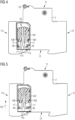
- FIG. 6 and 7 is an alternative exemplary embodiment of a plug-in summation current transformer 100' according to the invention and an alternative modular corresponding thereto constructed residual current circuit breaker 1 'shown schematically.
- figure 6 shows the alternative plug-in summation current transformer 100', which for a two-pole residual current circuit breaker 1' (see figure 7 ) is provided and therefore has only two primary conductors 110', 120', which in turn are passed twice through the magnetic core 102'.
- the magnetic core 102 ' is now erected, so that the primary conductor 110', 120' from top to bottom - ie passed from the front side 11 to the attachment side 12 through the opening of the magnetic core 102 '.
- the first and second ends 111', 112', 121', 122' of the two primary conductors 110' and 120' are in turn angled outwards, so that between the primary conductor ends 111', 112', 121', 122' and the Housing 101' of the two-pole plug-in summation current transformer 100' results in a free space defined by the distance from the magnetic core 102', into which the connecting elements 26 protrude without the primary conductor ends 111, 112, 121, 122, 131, 132, 141 , 142 to collide.
- the two-pole residual current circuit breaker 1' shown in a side view accordingly has only two modules - an RCD module 2 and an MCB module 3 (see figures 1 and 2 ) - which structurally each of the modules 2, 3 of the Figures 1 to 5 correspond to the illustrated and described modules 2, 3 and each have an independent, structurally mechanically stable insulating material housing 10.
- This design makes it possible to combine modular protective switching devices, for example two-, three- or four-pole residual current circuit breakers 1, 1', with cross-module assemblies such as the plug-in summation current transformer 100, 100', with the respective plug-in summation current transformer 100, 100' is specially adapted to the modular conditions of the respective residual current circuit breaker 1, 1'.
- FIG figure 8 the assembly method according to the invention for a modular residual current circuit breaker 1, 1' of the type described above is illustrated in FIG figure 8 briefly explained:
- a first step S1 at least one MCB module 3 is attached to an RCD module 2, so that a residual current circuit breaker 1, 1′ with an installation space 16 covering all modules is formed. If only one MCB module 3 is used, a two-pole residual current circuit breaker 1' is created, and if three MCB modules are installed, a four-pole residual current circuit breaker 1 results.
- plug-in summation current transformers 100, 100' suitable for the respective residual current circuit breaker 1, 1' are inserted in an insertion direction R1 into the multi-module installation space 16.
- joints are made between the first ends or second ends 111, 112, 121, 122, 131, 132, 141, 142, 111', 112', 121', 122' of the primary conductors 110, 120, 130 , 140, 110', 120' and the connection element 26 of the respective module 2, 3 which is clearly assigned to the respective primary conductor end 111, 112, 121, 122, 131, 132, 141, 142, 111', 112', 121', 122' manufactured.
- the joint can be mechanical, for example by clamping or crimping, and also thermal, for example by soldering, brazing or welding. Combinations of the different joining methods are also possible.
- step S3 in which the insertable summation current transformer 100, 100' is inserted in an insertion direction R2 oriented transversely to the insertion direction is moved until the primary conductor ends 111, 112, 121, 122, 131, 132, 141, 142, 111', 112', 121', 122' are in the immediate vicinity of the connection element 26 assigned to them.
- the assembly sequence is independent of whether it is a two-pole, three-pole or four-pole residual current circuit breaker 1, 1'.
Abstract
Der erfindungsgemäße Einschub-Summenstromwandler (100, 100') für einen aus mehreren Einzelmodulen (2, 3) gebildeten Fehlerstromschutz-schalter (1, 1') weist einen in einem Gehäuse (101, 101') aufgenommenen und gehalterten Magnetkern (102, 102') auf, durch dessen Öffnung zumindest zwei starre Primärleiter (110, 120, 130, 140, 110', 120') hindurchgeführt sind. Dabei weist jeder der Primärleiter (110, 120, 130, 140, ) ein erstes Ende (111, 121, 131, 141, 111', 121') und ein zweites Ende (112, 122, 132, 142, 112', 122') zur Kontaktierung mit je einem Anschlusselement (26) des dem jeweiligen Primärleiter (110, 120, 130, 140, 110', 120') eindeutig zugeordneten Moduls (2, 3) auf. Weiterhin weist der Einschub-Summenstromwandler (100, 100') Führungskonturen (108, 108') auf, die einen Einschub des Einschub-Summenstromwandlers (100, 100') entlang einer Einschubrichtung (R1) in einen sich über die mehreren Module (2, 3) des Fehlerstromschutzschalters (1, 1') erstreckenden, seitlich offenen Einbauraum (16) erlauben, wobei die Enden (111, 112, 121, 122, 131, 132, 141, 142, 111', 112', 121', 122') der Primärleiter (110, 120, 130, 140, 110', 120') nach dem Einschub in unmittelbarer Nähe zu den ihnen jeweils zugeordneten Anschlusselementen (26) angeordnet sind. Auf diese Weise wird die Montage des Summenstromwandlers deutlich vereinfacht.The plug-in summation current transformer (100, 100') according to the invention for a residual current circuit breaker (1, 1') formed from several individual modules (2, 3) has a magnetic core (102, 102 ') through whose opening at least two rigid primary conductors (110, 120, 130, 140, 110', 120') are passed. Each of the primary conductors (110, 120, 130, 140, ) has a first end (111, 121, 131, 141, 111', 121') and a second end (112, 122, 132, 142, 112', 122 ') for making contact with a respective connection element (26) of the module (2, 3) uniquely assigned to the respective primary conductor (110, 120, 130, 140, 110', 120'). Furthermore, the plug-in summation current transformer (100, 100') has guide contours (108, 108') which allow the plug-in summation current transformer (100, 100') to be inserted along an insertion direction (R1) in a manner extending over the plurality of modules (2, 3) of the fault current circuit breaker (1, 1') extending, laterally open installation space (16), with the ends (111, 112, 121, 122, 131, 132, 141, 142, 111', 112', 121', 122 ') the primary conductors (110, 120, 130, 140, 110', 120') are arranged after insertion in the immediate vicinity of the connection elements (26) assigned to them. This significantly simplifies the installation of the summation current transformer.
Description
Die Erfindung betrifft einen Einschub-Summenstromwandler für einen aus mehreren Modulen gebildeten Fehlerstromschutzschalter, beispielsweise ein FI/LS bzw. RCBO. Weiterhin betrifft die Erfindung einen modularen Fehlerstromschutzschalter mit einem derartigen Einschub-Summenstromwandler sowie ein Montageverfahren für einen derartigen Fehlerstromschutzschalter.The invention relates to a plug-in summation current transformer for a residual current circuit breaker formed from several modules, for example an FI/LS or RCBO. Furthermore, the invention relates to a modular residual current circuit breaker with such a plug-in summation current transformer and an assembly method for such a residual current circuit breaker.
Elektromechanische Schutzschaltgeräte - beispielsweise Leistungsschalter, Leitungsschutzschalter, Fehlerstromschutzschalter sowie Lichtbogen- bzw. Brandschutzschalter - dienen der Überwachung sowie der Absicherung eines elektrischen Stromkreises und werden insbesondere als Schalt- und Sicherheitselemente in elektrischen Energieversorgungs- und Verteilnetzen eingesetzt. Zur Überwachung und Absicherung des elektrischen Stromkreises wird das Schutzschaltgerät über zwei oder mehrere Anschlussklemmen mit einer elektrischen Leitung des zu überwachenden Stromkreises elektrisch leitend verbunden, um bei Bedarf den elektrischen Strom in der jeweiligen überwachten Leitung zu unterbrechen. Das Schutzschaltgerät weist hierzu zumindest einen Schaltkontakt auf, der bei Auftreten eines vordefinierten Zustandes - beispielsweise bei Erfassen eines Kurzschlusses oder eines Fehlerstromes - geöffnet werden kann, um den überwachten Stromkreis vom elektrischen Leitungsnetz zu trennen. Derartige Schutzschaltgeräte sind auf dem Gebiet der Niederspannungstechnik auch als Reiheneinbaugeräte bekannt.Electromechanical protective switching devices - for example circuit breakers, miniature circuit breakers, residual current circuit breakers and arcing or fire protection switches - are used to monitor and protect an electrical circuit and are used in particular as switching and safety elements in electrical energy supply and distribution networks. To monitor and protect the electrical circuit, the protective switching device is electrically conductively connected to an electrical line of the circuit to be monitored via two or more connection terminals in order to interrupt the electrical current in the respective monitored line if necessary. For this purpose, the protective switching device has at least one switching contact which can be opened when a predefined state occurs—for example when a short circuit or a fault current is detected—in order to separate the monitored circuit from the electrical mains. Such protective switching devices are also known as modular installation devices in the field of low-voltage technology.
Leistungsschalter sind dabei speziell für hohe Ströme ausgelegt. Ein Leitungsschutzschalter (sogenannter LS-Schalter), welcher auch als "Miniature Circuit Breaker" (MCB) bezeichnet wird, stellt in der Elektroinstallation eine sogenannte Überstromschutzeinrichtung dar und wird insbesondere im Bereich der Niederspannungsnetze eingesetzt. Leistungsschalter und Leitungsschutzschalter garantieren ein sicheres Abschalten bei Kurzschluss und schützen Verbraucher und Anlagen vor Überlast, beispielsweise vor Beschädigung der elektrischen Leitungen durch zu starke Erwärmung in Folge eines zu hohen elektrischen Stromes. Sie sind dazu ausgebildet, einen zu überwachenden Stromkreis im Falle eines Kurzschlusses oder bei Auftreten einer Überlast selbsttätig abzuschalten und damit vom übrigen Leitungsnetz zu trennen. Leistungsschalter und Leitungsschutzschalter werden daher insbesondere als Schalt- und Sicherheitselemente zur Überwachung und Absicherung eines elektrischen Stromkreises in elektrischen Energieversorgungsnetzen eingesetzt. Leitungsschutzschalter sind aus den Druckschriften
Zur Unterbrechung einer einzigen Phasenleitung wird in der Regel ein einpoliger Leitungsschutzschalter verwendet, welche üblicher Weise eine Breite von einer Teilungseinheit (entspricht ca. 18mm) aufweist. Für dreiphasige Anschlüsse werden (alternativ zu drei einpoligen Schaltgeräten) dreipolige Leitungsschutzschalter eingesetzt, welche dementsprechend eine Breite von drei Teilungseinheiten (entspricht ca. 54mm) aufweisen. Jedem der drei Phasenleiter ist dabei ein Pol, d.h. eine Schaltstelle zugeordnet. Soll zusätzlich zu den drei Phasenleitern auch noch der Neutralleiter unterbrochen werden, spricht man von vierpoligen Geräten, welche vier Schaltstellen aufweisen: drei für die drei Phasenleiter sowie einen für den gemeinsamen Neutralleiter.To interrupt a single phase line, a single-pole circuit breaker is usually used, which usually has a width of one pitch unit (corresponds to approx. 18mm). For three-phase connections (as an alternative to three single-pole switching devices), three-pole miniature circuit breakers are used, which accordingly have a width of three modular widths (corresponds to approx. 54mm). A pole, i.e. a switching point, is assigned to each of the three phase conductors. If the neutral conductor is to be interrupted in addition to the three phase conductors, this is referred to as a four-pole device, which has four switching points: three for the three phase conductors and one for the shared neutral conductor.
Daneben existieren kompakte Leitungsschutzschalter, welche bei einer Gehäusebreite von nur einer Teilungseinheit zwei Schaltkontakte für je eine Anschlussleitung, d.h. entweder für zwei Phasenleitungen (Kompaktleitungsschutzschalter vom Typ 1+1) oder für eine Phasenleitung und den Neutralleiter (Kompaktleitungsschutzschalter vom Typ 1+N), bereitstellen.In addition, there are compact miniature circuit breakers which, with a housing width of just one pitch unit, provide two switching contacts for one connecting cable each, i.e. either for two phase cables (compact miniature circuit breakers of type 1+1) or for a phase cable and the neutral conductor (compact miniature circuit breaker of type 1+N). .
Derartige Kompakt-Schutzschaltgeräte in Schmalbauweise sind beispielsweise aus den Druckschriften
Ein Fehlerstromschutzschalter ist eine Schutzeinrichtung zur Gewährleistung eines Schutzes gegen einen gefährlichen Fehlerstrom in einer elektrischen Anlage. Ein derartiger Fehlerstrom - welcher auch als Differenzstrom bezeichnet wird - tritt auf, wenn ein spannungsführendes Leitungsteil einen elektrischen Kontakt gegen Erde aufweist. Dies ist beispielsweise dann der Fall, wenn eine Person ein spannungsführendes Teil einer elektrischen Anlage berührt: in diesem Fall fließt der Strom als Fehlerstrom durch den Körper der betreffenden Person gegen die Erdung ab. Zum Schutz gegen derartige Körperströme muss der Fehlerstromschutzschalter bei Auftreten eines derartigen Fehlerstroms die elektrische Anlage schnell und sicher allpolig vom Leitungsnetz trennen. Im Allgemeinen Sprachgebrauch werden anstelle des Begriffs "Fehlerstromschutzschalter" auch die Begriffe FI-Schutzschalter (kurz: FI-Schalter), Differenzstromschutzschalter (kurz: DI-Schalter) oder RCD (für "Residual Current Protective Device") gleichwertig verwendet.A residual current circuit breaker is a protective device to ensure protection against a dangerous residual current in an electrical system. Such a fault current - which is also referred to as differential current - occurs when a live part of the line has an electrical contact to earth. This is the case, for example, when a person touches a live part of an electrical installation: in this case, the current flows as a fault current through the person's body towards earth. To protect against such body currents, the fault current circuit breaker must quickly and safely disconnect all poles of the electrical system from the mains when such a fault current occurs. In general usage, instead of the term "residual current circuit breaker", the terms FI circuit breaker (short: FI switch), residual current circuit breaker (short: DI switch) or RCD (for "Residual Current Protective Device") are used equivalently.
Bei Fehlerstromschutzschaltern wird ferner zwischen netzspannungsabhängigen und netzspannungsunabhängigen Gerätetypen unterschieden: während netzspannungsabhängige Fehlerstromschutzschalter eine Steuerungselektronik mit einem Auslöser aufweisen, die zur Erfüllung ihrer Funktion auf eine Hilfs- oder Netzspannung angewiesen ist, benötigen netzspannungsunabhängige Fehlerstromschutzschalter zur Realisierung der Auslösefunktion keine Hilfs- oder Netzspannung, sondern weisen zur Realisierung der netzspannungsunabhängigen Auslösung in der Regel einen etwas größeren Summenstromwandler auf, wodurch ein größerer Induktionsstrom in der Sekundärwicklung erzeugt werden kann.In the case of residual current circuit breakers, a distinction is also made between mains voltage-dependent and mains voltage-independent device types: while mains-voltage-dependent residual current circuit breakers have control electronics with a trigger that is dependent on an auxiliary or mains voltage to fulfill their function, mains-voltage-independent residual current circuit breakers do not need an auxiliary or mains voltage to implement the tripping function, but instead have an electronic control system To implement mains-voltage-independent tripping, they usually have a slightly larger summation current transformer, which means that a larger induction current can be generated in the secondary winding.
Daneben existieren auch Gerätebauformen, bei denen die Funktionalität eines Fehlerstrom-Schutzschalters mit der Funktionalität eines Leitungsschutzschalters kombiniert wird: derartige kombinierte Schutzschaltgeräte werden im Deutschen als FI/LS oder im englischsprachigen Raum als RCBO (für Residual current operated Circuit-Breaker with Overcurrent protection) bezeichnet. Diese Kombigeräte haben im Vergleich zu getrennten Fehlerstrom- und Leitungsschutzschaltern den Vorteil, dass jeder Stromkreis seinen eigenen Fehlerstrom-Schutzschalter aufweist: Normalerweise wird ein einziger FehlerstromSchutzschalter für mehrere Stromkreise verwendet. Kommt es zu einem Fehlerstrom, werden somit in Folge alle abgesicherten Stromkreise abgeschaltet. Durch den Einsatz von RCBOs wird nur der jeweils betroffene Stromkreis abgeschaltet.In addition, there are also device designs in which the functionality of a residual current circuit breaker is combined with the functionality of a miniature circuit breaker: such combined protective switching devices are referred to in German as FI/LS or in English-speaking countries as RCBO (for residual current operated circuit breaker with overcurrent protection). . Compared to separate residual current circuit breakers and miniature circuit breakers, these combination devices have the advantage that each circuit has its own residual current circuit breaker: Normally, a single residual current circuit breaker is used for several circuits. If there is a residual current, all of the protected circuits are switched off as a result. By using RCBOs, only the affected circuit is switched off.
Zur Erfassung eines derartigen Fehler- bzw. Differenzstromes wird die Größe des Stromes in einer zu einem elektrischen Verbraucher hinführenden Leitung, beispielsweise einer Phasenleitung, mit der Größe des Stromes in einer vom elektrischen Verbraucher zurückführenden Leitung, beispielsweise eines Neutralleiters, mit Hilfe eines sogenannten Summenstromwandlers verglichen. Dieser weist einen ringförmigen Magnetkern auf, durch den die Primärleiter (hin- und rückführende elektrische Leitungen) hindurchgeführt sind. Der Magnetkern selbst ist mit einem Sekundärleiter bzw. einer Sekundärwicklung umwickelt. Im fehlerstromfreien Zustand ist die Summe der zu dem Verbraucher hinfließenden elektrischen Ströme gleich der Summe der vom Verbraucher zurückfließenden elektrischen Ströme. Werden die Ströme vektoriell, d.h. richtungsbezogen bzw. vorzeichenbehaftet, addiert, so folgt hieraus, dass die vorzeichenbehaftete Summe der elektrischen Ströme in den Hin- und Rückleitungen im fehlerstromfreien Zustand gleich Null ist: im Sekundärleiter wird kein Induktionsstrom induziert. Im Unterschied dazu ist im Falle eines Fehler- bzw. Differenzstromes, der gegen Erde abfließt, die im Summenstromwandler erfasste Summe der hin- beziehungsweise zurückfließenden elektrischen Ströme ungleich Null. Die dabei auftretende Stromdifferenz führt dazu, dass an der Sekundärwicklung eine der Stromdifferenz proportionale Spannung induziert wird, wodurch ein Sekundärstrom in der Sekundärwicklung fließt. Dieser Sekundärstrom dient als Fehlerstromsignal und führt nach Überschreiten eines vorbestimmten Wertes zum Auslösen des Schutzschaltgerätes und infolgedessen - durch Öffnen des zumindest einen Schaltkontaktes des Schutzschaltgerätes - zur Abschaltung des entsprechend abgesicherten Stromkreises.To detect such a fault or differential current, the size of the current in a line leading to an electrical load, for example a phase line, is compared with the size of the current in a line leading back from the electrical load, for example a neutral conductor, using a so-called summation current transformer . This has a ring-shaped magnetic core through which the primary conductors (return electrical lines) are passed. The magnetic core itself is wrapped with a secondary conductor or a secondary winding. In the fault-free state, the sum of the electrical currents flowing to the consumer is equal to the sum of the electrical currents flowing back from the consumer. If the currents are added vectorially, ie directional or signed, it follows that the signed sum of the electric currents in the outgoing and return lines in the fault-free state is equal to zero: no induction current is induced in the secondary conductor. In contrast to this, in the case of a fault or differential current that flows to earth, the sum of the electrical currents flowing in or out, which is recorded in the summation current transformer, is not equal to zero. The ones there Any current difference that occurs leads to a voltage proportional to the current difference being induced in the secondary winding, as a result of which a secondary current flows in the secondary winding. This secondary current serves as a residual current signal and, when a predetermined value is exceeded, triggers the protective switching device and as a result—by opening the at least one switching contact of the protective switching device—the correspondingly secured circuit is switched off.
Insbesondere bei mehrpoligen Fehlerstromschutzschaltern - ob als reiner Fehlerstromschutzschalter oder als kombinierte Gärätebauform wie FI/LS bzw. RCBO - müssen bei der Montage des Summenstromwandlers die die vergleichsweise dicken Primärleiter manuell durch den ringförmigen Magnetkern hindurch gefädelt werden. Gerade bei kompakten Schutz- oder Messeinrichtungen, welche nur über einen geringen Bauraum verfügen, ist eine derartige Montage vergleichsweise aufwändig und zwingend von Hand auszuführen.Especially with multi-pole residual current circuit breakers - whether as a pure residual current circuit breaker or as a combined device design such as FI/LS or RCBO - the comparatively thick primary conductors must be threaded manually through the ring-shaped magnetic core when installing the summation current transformer. In the case of compact protective or measuring devices in particular, which only have a small installation space, such an assembly is comparatively complex and must be carried out by hand.
Es ist deshalb die Aufgabe der vorliegenden Erfindung, einen Einschub-Summenstromwandler für einen aus mehreren Einzelmodulen gebildeten Fehlerstromschutzschalter, einen modularen Fehlerstromschutzschalter mit einem derartigen Einschub-Summenstromwandler sowie ein Montageverfahren für einen derartigen Fehlerstromschutz-schalter bereitzustellen, welche sich durch eine vereinfachte Montage auszeichnen.It is therefore the object of the present invention to provide a plug-in total current circuit breaker for a residual current circuit breaker formed from several individual modules, a modular residual current circuit breaker with such a plug-in total current circuit breaker and an assembly method for such a residual current circuit breaker, which are characterized by simplified assembly.
Diese Aufgabe wird erfindungsgemäß durch den Einschub-Summenstromwandler für einen aus mehreren Einzelmodulen gebildeten Fehlerstromschutzschalter, den modularen Fehlerstromschutzschalter mit einem derartigen Einschub-Summenstromwandler sowie das Montageverfahren für einen derartigen Fehlerstromschutz-schalter gemäß den unabhängigen Ansprüchen gelöst. Vorteilhafte Ausgestaltungen sind Gegenstand der abhängigen Ansprüche.This object is achieved according to the invention by the plug-in summation current transformer for a residual current circuit breaker formed from several individual modules, the modular residual current circuit breaker with such a plug-in summation current transformer and the assembly method for such a residual current circuit breaker according to the independent claims. Advantageous configurations are the subject matter of the dependent claims.
Der erfindungsgemäße Einschub-Summenstromwandler für einen aus mehreren Einzelmodulen gebildeten Fehlerstromschutzschalter weist einen in einem Gehäuse aufgenommenen und gehalterten Magnetkern auf, durch dessen Öffnung zumindest zwei starre Primärleiter hindurchgeführt sind. Dabei weist jeder der Primärleiter ein erstes Ende und ein zweites Ende zur Kontaktierung mit je einem Anschlusselement des dem jeweiligen Primärleiter eindeutig zugeordneten Moduls auf. Weiterhin weist der Einschub-Summenstromwandler zumindest eine Führungskontur auf, die einen geführten Einschub des Einschub-Summenstromwandlers entlang einer Einschubrichtung in einen sich über die mehreren Module des Fehlerstromschutzschalters erstreckenden, seitlich offenen Einbauraum ermöglichen, wobei die Enden der Primärleiter nach dem Einschub eine vordefinierte Position zu den ihnen jeweils zugeordneten Anschlusselementen einnehmen.The plug-in summation current transformer according to the invention for a residual current circuit breaker formed from several individual modules has a magnetic core which is accommodated and held in a housing and through the opening of which at least two rigid primary conductors are passed. Each of the primary conductors has a first end and a second end for making contact with a respective connection element of the module that is uniquely assigned to the respective primary conductor. Furthermore, the plug-in summation current transformer has at least one guide contour that allows the plug-in summation current transformer to be inserted along a direction of insertion into an installation space that is open at the side and extends over the multiple modules of the residual current circuit breaker, with the ends of the primary conductors moving to a predefined position after insertion occupy the connection elements assigned to them.
Die Verwendung des erfindungsgemäßen Einschub-Summenstromwandlers hat den Vorteil, dass die starren Primärleiter vor der Montage des Summenstromwandlers im Fehlerstromschutzschalter - und damit außerhalb des Fehlerstromschutzschaltergehäuses - durch den Magnetkern hindurchgeführt werden. Der Magnetkern kann dabei rohr- oder ringförmig ausgebildet sein. Ist er aus Bandmaterial gewickelt, so spricht man von einem Ringbandkern. Ferner kann der Magnetkern in einer eigenen Schutzhülle aufgenommen und gehaltert sein.The use of the plug-in summation current transformer according to the invention has the advantage that the rigid primary conductors are passed through the magnet core before the summation current transformer is installed in the residual current circuit breaker—and thus outside the residual current circuit breaker housing. The magnetic core can be tubular or ring-shaped. If it is wound from strip material, it is called a toroidal strip core. Furthermore, the magnet core can be accommodated and held in its own protective cover.
Unter dem Begriff "starr" ist dabei zu verstehen, dass die Primärleiter eine Eigenstabilität aufweisen, so dass sie ihre Form behalten. Insbesondere die ersten und zweiten Enden der Primärleiter, welche in einem späteren Montageschritt mit einem jeweiligen Anschlusselement des Fehlerstromschutzschalters kontaktiert werden, weisen nach der Montage des Einschub-Summenstromwandlers, d.h. nach dem Einschieben des Einschub-Summenstromwandlers in den dafür vorgesehenen Einbauraum des Fehlerstromschutzschalters, eine jeweils vordefinierte Position - benachbart zu dem jeweils zugeordneten Anschlusselement - auf.The term "rigid" is to be understood here as meaning that the primary conductors have an inherent stability, so that they retain their shape. In particular, the first and second ends of the primary conductors, which are contacted with a respective connection element of the residual current circuit breaker in a later assembly step, each have a predefined Position - adjacent to the associated connection element - on.
Die Anzahl der durch den Magnetkern hindurchzuführenden Primärleiter korrespondiert dabei mit der Anzahl der Einzelmodule des Fehlerstromschutzschalters, wobei jedem Modul des Fehlerstromschutzschalters jeweils einer der Primärleiter eindeutig zugeordnet ist: bei einem aus zwei Modulen gebildeten zweipoligen Fehlerstromschutzschalter sind dementsprechend zwei Primärleiter - einer zur Kontaktierung mit einem Neutralleiter, ein weiterer zur Kontaktierung mit einem Phasenleiter - vorzusehen. Bei einem aus drei Modulen gebildeten dreipoligen Fehlerstromschutzschalter sind entsprechend drei Primärleiter - einer zur Kontaktierung mit dem Neutralleiter, zwei weitere zur Kontaktierung mit jeweils einem Phasenleiter - vorzusehen. Bei einem aus vier Modulen gebildeten vierpoligen Fehlerstromschutzschalter sind es vier Primärleiter: einer zur Kontaktierung mit dem Neutralleiter, drei weitere zur Kontaktierung mit jeweils einem Phasenleiter.The number of primary conductors to be passed through the magnetic core corresponds to the number of individual modules of the residual current circuit breaker, with each module of the residual current circuit breaker being clearly assigned one of the primary conductors: in the case of a two-pole residual current circuit breaker formed from two modules, there are accordingly two primary conductors - one for contacting a neutral conductor , another for contacting a phase conductor - to be provided. In the case of a three-pole fault current circuit breaker formed from three modules, three primary conductors must be provided - one for contacting the neutral conductor, two more for contacting each phase conductor. In the case of a four-pole residual current circuit breaker formed from four modules, there are four primary conductors: one for contacting the neutral conductor, three others for contacting each phase conductor.
Die Führungskonturen sind am Gehäuse des Einschub-Summenstromwandlers ausgebildet und dienen dazu, das Einführen des Einschub-Summenstromwandlers in einer Einschubrichtung in einen sich über die mehreren Module des Fehlerstromschutzschalters erstreckenden, seitlich offenen Einbauraum zu erleichtern. Insbesondere dienen sie dazu, eine Kollision der ersten und zweiten Enden der Primärleiter mit den in den Einbauraum hineinragenden Anschlusselementen des Fehlerstromschutzschalters während des Einschiebens in der Einschubrichtung zu verhindern. Bei den Führungskonturen kann es sich beispielsweise um am Gehäuse ausgebildete Stege, Nasen oder Anschlagsflächen handeln, welche eine vordefinierte räumliche Positionierung des Einschub-Summenstromwandlers während der Einschubbewegung ermöglichen.The guide contours are formed on the housing of the plug-in summation current transformer and serve to facilitate the insertion of the plug-in summation current transformer in an insertion direction into an installation space that is open at the side and extends over the several modules of the residual current circuit breaker. In particular, they serve to prevent the first and second ends of the primary conductors from colliding with the connection elements of the residual current circuit breaker that protrude into the installation space during insertion in the insertion direction. The guide contours can be webs, lugs or stop surfaces formed on the housing, for example, which enable a predefined spatial positioning of the plug-in summation current transformer during the plug-in movement.
In einer vorteilhaften Weiterbildung des Einschub-Summenstromwandlers ist jeder der Primärleiter zumindest zweimal durch die Öffnung des Magnetkerns geführt. Dies bedeutet, dass jeder Primärleiter auf der Außenseite des Einschub-Summenstromwandlers zumindest einmal zurückgeführt werden muss. Durch die daraus resultierende höhere Windungszahl der Primärleiter ist auf der Sekundärseite des Einschub-Summenstromwandlers ein höherer Sekundärstrom realisierbar.In an advantageous development of the plug-in summation current transformer, each of the primary conductors is at least twice through the opening of the magnetic core. This means that each primary conductor must be routed back at least once on the outside of the summation current transformer. Due to the resulting higher number of turns in the primary conductor, a higher secondary current can be realized on the secondary side of the plug-in summation current transformer.
In einer weiteren vorteilhaften Weiterbildung des Einschub-Summenstromwandlers sind das erste und das zweite Ende eines jeden Primärleiters quer zur Einschubrichtung einander entgegengesetzt orientiert. Durch die entgegengesetzte Orientierung des ersten und zweiten Endes eines jeden Primärleiters ist ein gewisser Abstand der Primärleiterenden realisierbar, so dass Fehler bei der Kontaktierung - Berührungen, Fehlkontaktierungen, etc. wirksam vermieden werden können. Jedem Primärleiter ist dabei ein Modul des Fehlerstromschutzschalters eindeutig zugeordnet. Die beiden Enden eines Primärleiters befinden sich damit in Einschubrichtung "auf gleicher Höhe", so dass sie nach dem Einschieben innerhalb des ihnen zugeordneten Moduls und benachbart zu dem ihnen jeweils zugeordneten Anschlusselement positioniert sind.In a further advantageous development of the plug-in summation current transformer, the first and the second end of each primary conductor are oriented opposite to one another transversely to the direction of insertion. Due to the opposite orientation of the first and second end of each primary conductor, a certain distance between the ends of the primary conductor can be realized, so that errors in contacting—touching, incorrect contacting, etc.—can be effectively avoided. A module of the residual current circuit breaker is clearly assigned to each primary conductor. The two ends of a primary conductor are thus located “at the same height” in the direction of insertion, so that, after being inserted, they are positioned within the module assigned to them and adjacent to the connection element assigned to them.
In einer weiteren vorteilhaften Weiterbildung des Einschub-Summenstromwandlers sind die ersten Enden der Primärleiter in der Einschubrichtung hintereinander angeordnet. Auch die zweiten Enden der Primärleiter sind in der Einschubrichtung hintereinander angeordnet. Indem die ersten Enden der Primärleiter sowie die zweiten enden der Primärleiter jeweils hintereinander in einer Reihe angeordnet sind, können Kollisionen der Primärleiterenden mit in den Einbauraum hineinragenden Bauteilen des Fehlerstromschutzschalters vermieden werden.In a further advantageous development of the plug-in summation current transformer, the first ends of the primary conductors are arranged one behind the other in the plug-in direction. The second ends of the primary conductors are also arranged one behind the other in the insertion direction. By arranging the first ends of the primary conductors and the second ends of the primary conductors one behind the other in a row, collisions of the primary conductor ends with components of the residual current circuit breaker projecting into the installation space can be avoided.
In einer weiteren vorteilhaften Weiterbildung des Einschub-Summenstromwandlers weist das Gehäuse an seiner Außenseite mehrere Führungsstege zur Führung der Primärleiter auf. Mit Hilfe der Führungsstege werden den Primärleiter beim Bewickeln des Magnetkerns in einer vordefinierten Position gehalten. Damit können die Außenabmessungen des Einschub-Summenstromwandlers sicher eingehalten werden, was wegen der beengten Platzverhältnisse innerhalb des Einbauraums von Vorteil ist, um den dort maximal zur Verfügung stehenden Bauraum nicht zu überschreiten.In a further advantageous development of the plug-in summation current transformer, the housing has a plurality of guide webs on its outside for guiding the primary conductors. With the help of the guide webs, the primary conductors are wound of the magnetic core is held in a predefined position. The external dimensions of the plug-in summation current transformer can thus be reliably maintained, which is advantageous because of the cramped space conditions within the installation space, in order not to exceed the maximum space available there.
In einer weiteren vorteilhaften Weiterbildung des Einschub-Summenstromwandlers sind die Enden der Primärleiter nach unten beabstandet vom Gehäuse angeordnet. Auf diese Weise ist eine bessere Zugänglichkeit zu den Primärleiterenden gewährleistet, was insbesondere für den nachfolgenden Fügeprozess (Schweißen, Löten) von Vorteil ist. Somit kann auch der Energieeintrag beim Fügen der Primärleiterenden geringgehalten und damit die Gefahr einer Beschädigung des Einschub-Summenstromwandlers - insbesondere des Magnetkerns - reduziert werden.In a further advantageous development of the plug-in summation current transformer, the ends of the primary conductors are spaced downwards from the housing. This ensures better accessibility to the primary conductor ends, which is particularly advantageous for the subsequent joining process (welding, soldering). This means that the energy input when joining the primary conductor ends can also be kept low and the risk of damage to the plug-in summation current transformer - in particular the magnetic core - can be reduced.
In einer weiteren vorteilhaften Weiterbildung weist der Einschub-Summenstromwandler eine im Wesentlichen quaderförmige Außenkontur auf. Auf diese Weise ist eine kompakte Gestaltung realisierbar, wobei die quaderförmige Außenkontur zu dem im Wesentlichen quaderförmig gehaltenen Einbauraum des Fehlerstromschutzschalters korrespondiert.In a further advantageous development, the plug-in summation current transformer has an essentially cuboid outer contour. In this way, a compact design can be realized, with the cuboid outer contour corresponding to the essentially cuboid installation space of the residual current circuit breaker.
Der erfindungsgemäße modulare Fehlerstromschutzschalter weist ein als MCB-Modul ausgebildetes erstes Modul auf, in dem ein Strompfad zur Kontaktierung mit einem Phasenleiter angeordnet ist, welcher einen Schaltkontakt sowie eine Schaltmechanik mit einem magnetischen und einem thermischen Auslösesystem zur Unterbrechung des Schaltkontakts aufweist. Weiterhin weist der Fehlerstromschutzschalter ein als RCD-Modul ausgebildetes zweites Modul auf, in dem ein Strompfad zur Kontaktierung mit einem Neutralleiter angeordnet ist. Dabei weisen beide Module ein Isolierstoffgehäuse mit einer Frontseite, einer der Frontseite gegenüberliegend angeordnete Befestigungsseite, sowie mit die Front- und die Befestigungsseite verbindende Schmal- und Breitseiten auf und sind nebeneinander angeordnet. Die Isolierstoffgehäuse weisen jeweils eine sich von der einen zur anderen Breitseite erstreckende Einschuböffnung auf, wodurch bei einer Kombination des MCB-Moduls mit dem RCD-Modul ein modulübergreifenden Einbauraum gebildet ist, in dem ein modulübergreifender Einschub-Summenstromwandler der vorstehend beschriebenen Art aufgenommen und gehaltert ist.The modular residual current circuit breaker according to the invention has a first module designed as an MCB module, in which a current path for contacting a phase conductor is arranged, which has a switching contact and a switching mechanism with a magnetic and a thermal tripping system for interrupting the switching contact. Furthermore, the residual current circuit breaker has a second module designed as an RCD module, in which a current path for contacting a neutral conductor is arranged. In this case, both modules have an insulating material housing with a front side, a fastening side arranged opposite the front side, and with the front side and the fastening side connecting narrow and broad sides and are arranged next to each other. The insulating housings each have a slide-in opening that extends from one broad side to the other, so that when the MCB module is combined with the RCD module, a cross-module installation space is formed in which a cross-module plug-in summation current transformer of the type described above is accommodated and held .
Bei dem erfindungsgemäßen Fehlerstromschutzschalter handelt es sich um eine kombinierte Gerätebauform, bei der Funktionalität eines reinen Fehlerstrom-Schutzschalters mit der Funktionalität eines Leitungsschutzschalters kombiniert wird: im Deutschen werden derartige Kombi-Schutzschaltgeräte als FI/LS (Fehlerstrom/Leitungsschutz) bezeichnet, im englischsprachigen Raum ist hierfür der Begriff RCBO (für Residual current operated Circuit-Breaker with Overcurrent protection) gebräuchlich.The residual current circuit breaker according to the invention is a combined device design in which the functionality of a pure residual current circuit breaker is combined with the functionality of a circuit breaker: in German, such combination protective switching devices are referred to as FI/LS (fault current/line protection), in English-speaking countries it is the term RCBO (residual current operated circuit breaker with overcurrent protection) is used for this.
Unter dem Begriff "modular" ist zu verstehen, dass der Fehlerstromschutzschalter aus zwei Einzelmodulen - MCB-Modul und RCD-Modul - aufgebaut ist. Bei beiden Modulen handelt es sich dabei um strukturmechanisch stabile, geschlossene Module mit jeweils einem eigenen Isolierstoffgehäuse mit je einer Einschuböffnung, welche nach der Montage der beiden Module - Breitseite an Breitseite - einen modulübergreifenden Einbauraum zur Aufnahme und Montage des Einschub-Summenstromwandlers bilden. Innenliegend weisen die beiden Module jeweils einen Primärleiter-Strompfad - im Falle des RCD-Moduls für den Neutralleiter, beim MCB-Modul für einen Phasenleiter - auf. Auch die zur Realisierung der Funktionalität des jeweiligen Moduls erforderlichen Baugruppen und Komponenten - jeweils ein Schaltkontakt, Schalt- und Auslösemechanik (beim MCB-Modul für Kurzschluss und thermische Überlast, beim RCD-Modul für den Fehlerstromfall), Löscheinrichtung zur Lichtbogen-Löschung, etc. - sind in dem jeweiligen Modul angeordnet, d.h. aufgenommen und gehaltert.The term "modular" means that the residual current circuit breaker is made up of two individual modules - MCB module and RCD module. Both modules are structurally stable, closed modules, each with its own insulating housing, each with a slide-in opening, which after the assembly of the two modules - broad side to broad side - form a cross-module installation space for accommodating and installing the plug-in summation current transformer. Inside, the two modules each have a primary conductor current path - in the case of the RCD module for the neutral conductor, in the case of the MCB module for a phase conductor. The assemblies and components required to implement the functionality of the respective module - each with a switching contact, switching and tripping mechanism (with the MCB module for short circuit and thermal overload, with the RCD module for residual current), quenching device for arc quenching, etc. - Are arranged in the respective module, ie added and held.
Zwischen den beiden Schmalseiten ist der Einbauraum außermittig, d.h. zu einer der beiden Schmalseiten hin verschoben, angeordnet und über die in den beiden Breitseiten eines jeden Moduls von außen zugänglich. Nach der Montage der beiden Module (Breitseite an Breitseite) sind die beiden außenliegenden Breitseiten mittels geeigneter Verschlusselemente wie Deckel oder Klappen verschließbar. Die außermittige Anordnung hat den Vorteil, dass in diesem Bereich der den Fehlerstromschutzschalter bildenden Module freier Bauraum zur Verfügung steht, welcher für die Anordnung einer großvolumigen Baugruppe wie des Einschub-Summenstromwandlers genutzt werden kann. Auf diese Weise können die Module - und damit der Fehlerstromschutzschalter - kompakt gehalten werden, so dass jedes Modul eine Breite von lediglich einer Teilungseinheit, was ca. 18mm entspricht, aufweist. Der Fehlerstromschutzschalter weist dementsprechend eine Breite von einer Teilungseinheit je Modul -also zwei Teilungseinheiten bei einem aus zwei Modulen gebildeten zweipoligen Gerät - auf.The installation space is off-centre between the two narrow sides, i.e. shifted towards one of the two narrow sides, and is accessible from the outside via the two broad sides of each module. After the two modules have been assembled (broad side to broad side), the two outer broad sides can be closed using suitable locking elements such as covers or flaps. The off-centre arrangement has the advantage that in this area of the modules forming the residual current circuit breaker there is free installation space which can be used for arranging a large-volume assembly such as the plug-in summation current transformer. In this way, the modules - and thus the residual current circuit breaker - can be kept compact, so that each module has a width of only one pitch unit, which corresponds to about 18mm. Accordingly, the residual current circuit breaker has a width of one pitch unit per module—that is, two pitch units in the case of a two-pole device formed from two modules.
In einer vorteilhaften Weiterbildung weist der modulare Fehlerstromschutzschalter zumindest ein weiteres Modul, welches als MCB-Modul ausgebildet und neben dem ersten Modul angeordnet ist, auf. Durch Hinzunahme weiterer MCB-Module sind dreipolige (ein weiteres MCB-Modul) oder vierpolige (zwei weitere MCB-Module) FI/LS- bzw. RCBO-Geräte auf einfache Art und Weise realisierbar. Lediglich der in den gemeinsamen, modulübergreifenden Einbauraum einzuschiebende Summenstromwandler ist entsprechend zu modifizieren, d.h. für jedes weitere Modul ist ein weiterer Primärleiter vorzusehen. Die einzelnen Module werden dabei jeweils Breitseite an Breitseite nebeneinander angeordnet und mit Hilfe geeigneter Verbindungsmittel - beispielsweise Klammern, Niet- oder Schnappverbindungen - aneinander befestigt.In an advantageous development, the modular residual current circuit breaker has at least one further module, which is designed as an MCB module and is arranged next to the first module. By adding additional MCB modules, three-pole (one additional MCB module) or four-pole (two additional MCB modules) FI/LS or RCBO devices can be easily implemented. Only the summation current transformer to be inserted in the common, cross-module installation space has to be modified accordingly, ie an additional primary conductor must be provided for each additional module. The individual modules are arranged broadside to broadside next to each other and are fastened to one another with the aid of suitable connecting means, for example clamps, rivets or snap connections.
Das erfindungsgemäße Montageverfahren für einen modular aufgebauten Fehlerstromschutzschalter der vorstehend beschriebenen Art weist die Schritte
- a) Befestigen zumindest eines MCB-Moduls an einem RCD-Modul, so dass ein modulübergreifender Einbauraum gebildet ist;
- b) Einschieben eines gemäß der vorstehend beschriebenen Art gebildeten Einschub-Summenstromwandlers in den Einbauraum in einer Einschubrichtung (R1);
- c) Herstellen von Fügeverbindungen zwischen den ersten bzw. zweiten Enden der Primärleiter und einem dem jeweiligen Primärleiterende eindeutig zugeordneten Anschlusselement des jeweiligen Moduls.
- a) attaching at least one MCB module to an RCD module, so that a module-overlapping installation space is formed;
- b) inserting a plug-in summation current transformer formed according to the type described above into the installation space in an insertion direction (R1);
- c) Production of joints between the first and second ends of the primary conductors and a connection element of the respective module that is clearly assigned to the respective end of the primary conductor.
In einer vorteilhaften Weiterbildung weist das Montageverfahren den zusätzlichen Schritt
b1) Bewegen des Einschub-Summenstromwandlers in einer quer zur Einschubrichtung orientierten Einrückrichtung (R2), auf, wobei der zusätzliche Schritt b1) vor dem "Herstellen von Fügeverbindungen" ausgeführt wird. Auf diese Weise werden die Enden der Primärleiter erst nach dem Einschieben des Summenstromwandlers in den Einbauraum in unmittelbare Nähe zu dem jeweiligen Anschlusselement gebracht, so dass sie anschließend auf einfache Art und Weise verbunden werden können. Kollisionen während des Einschiebens werden dadurch sicher vermieden.In an advantageous development, the assembly method has the additional step
b1) moving the plug-in summation current transformer in a direction of engagement (R2) oriented transversely to the direction of insertion, the additional step b1) being carried out before the “production of joints”. In this way, the ends of the primary conductors are brought into the immediate vicinity of the respective connection element only after the summation current transformer has been pushed into the installation space, so that they can then be connected in a simple manner. This reliably avoids collisions during insertion.
In einer weiteren vorteilhaften Weiterbildung des Montageverfahrens erfolgt der Schritt c) "Herstellen von Fügeverbindungen" thermisch durch Löten oder Schweißen. Mit Hilfe dieser thermischen Fügeverfahren Löten und Schweißen kann eine feste, teilweise auch hochwarmfeste, und sichere Fügeverbindung zwischen den Primärleiterenden und dem diesem jeweils zugeordneten Anschlusselement realisiert werden.In a further advantageous development of the assembly method, step c) "creating joint connections" takes place thermally by soldering or welding. With the help of these thermal joining methods of soldering and welding, a strong, sometimes also highly heat-resistant, and secure joint can be realized between the primary conductor ends and the connection element assigned to them.
Im Folgenden werden Ausführungsbeispiele des erfindungsgemäßen Einschub-Summenstromwandlers, des erfindungsgemäßen modularen Fehlerstromschutzschalters sowie des erfindungsgemäßen Montageverfahrens unter Bezug auf die beigefügten Figuren näher erläutert. In den Figuren sind:Exemplary embodiments of the plug-in summation current transformer according to the invention, the modular residual current circuit breaker according to the invention and the assembly method according to the invention are explained in more detail below with reference to the attached figures. In the figures are:
- 1 und 21 and 2
- schematische Darstellungen des erfindungsgemäßen modularen Fehlerstromschutzschalters;schematic representations of the modular residual current circuit breaker according to the invention;
- Figur 3figure 3
- ein erstes Ausführungsbeispiel des erfindungsgemäßen Einschub-Summenstromwandlers;a first embodiment of the plug-in summation current transformer according to the invention;
- Figuren 4 und 5Figures 4 and 5
-
schematische Seitenansichten des zu
Figur 3 korrespondierenden Fehlerstromschutzschalters in verschiedenen Montagezuständen;schematic side views of the tofigure 3 corresponding residual current circuit breaker in different assembly states; - Figur 6figure 6
- ein weiteres Ausführungsbeispiel des erfindungsgemäßen Einschub-Summenstromwandlers;another embodiment of the plug-in summation current transformer according to the invention;
- Figur 7figure 7
-
ein weiteres Ausführungsbeispiel eines zu
Figur 6 korrespondierenden erfindungsgemäßen modularen Fehlerstromschutzschalters;another embodiment of a toofigure 6 corresponding modular residual current circuit breaker according to the invention; - Figur 8figure 8
- eine schematische Darstellung des erfindungsgemäßen Montageverfahrens.a schematic representation of the assembly method according to the invention.
In den verschiedenen Figuren der Zeichnung sind gleiche Teile stets mit dem gleichen Bezugszeichen versehen. Die Beschreibung gilt für alle Zeichnungsfiguren, in denen das entsprechende Teil ebenfalls zu erkennen ist.In the various figures of the drawing, the same parts are always provided with the same reference numbers. The description applies to all drawing figures in which the corresponding part can also be seen.
In den
Die Isolierstoffgehäuse 10 sind jeweils in Schmalbauweise ausgeführt und weist eine Breite B von einer Teilungseinheit (1TE, entspr. ca. 18mm) auf, wobei die Außenmaße definierende Hüllflächen durch eine Frontseite 11, eine der Frontseite 11 gegenüberliegend angeordnete Befestigungsseite 12, sowie die Front- und die Befestigungsseite 11, 12 verbindende Schmalseiten 13 und Breitseiten 14 gebildet sind. Im Bereich der Schmalseiten sind jeweils Schraubklemmen 19 zur Kontaktierung mit netz- bzw. lastseitigen Anschlussleitern (nicht dargestellt) im jeweiligen Isolierstoffgehäuse 10 des jeweiligen Moduls aufgenommen und gehaltert. Zur manuellen Betätigung weist jedes der Module 2, 3 ein im Bereich seiner Frontseite 11 angeordnetes Betätigungselement 23 auf. Eine gemeinsame Betätigung der einzelnen Betätigungselemente 23 ist mittels eines die einzelnen Betätigungselemente 23 koppelndes Verbindungselements 24 realisiert.The insulating
In der Regel weisen Isolierstoffgehäuse 10 in Schmalbauweise zwei Halbschalen auf, welche am Ende der Montage des Niederspannungs-Schutzschaltgerätes 1 mittels geeigneter Verbindungsmittel, beispielsweise Niet- oder Rastverbindungen, unter Ausbildung einer umlaufenden Fügelinie zusammengefügt werden. Zu jeder Halbschale gehört dabei eine der Breitseiten 14 sowie Teile (ganz oder vollständig) der Front-, Befestigungs- und Schmalseiten 11, 12, 13.As a rule, insulating
In den Breitseiten 14 jedes der Isolierstoffgehäuse 10 ist eine Einschuböffnung ausgebildet, welche sich orthogonal zu den Breitseiten 14 von der einen zur anderen Breitseite 14 erstreckt, wodurch ein Einbauraum 16 gebildet ist. In den Einbauraum 16 ragen seitlich elektrische Anschlusselemente 26 des jeweiligen Moduls 2, 3 hinein. Durch die Montage der einzelnen Module 2, 3 zu einem mehrpoligen Gerät, hier zu dem vierpoligen FI/LS bzw. RCBO, wird aus den Einbauräumen 16 ein modulübergreifender Einbauraum 16 gebildet, in dem eine großvolumige Baugruppe, beispielsweise ein Einschub-Summenstromwandler 100 (siehe
In
Um das Einschieben des Einschub-Summenstromwandlers 100 in den Einbauraum 16 zu erleichtern sowie um Kollisionen der ersten und zweiten Enden 111, 112, 121, 122, 131, 132, 141, 142 der Primärleiter 110, 120, 130, 140 mit den in den Einbauraum 16 ragenden Anschlusselementen 26 zu vermeiden weist der Einschub-Summenstromwandler 100 Führungskonturen 108 auf, welche beim Einschieben des Einschub-Summenstromwandlers 100 in den Einbauraum 16 an dort ausgebildeten, korrespondierenden Anlageflächen 17 (siehe
Um eine bessere magnetische Induktion des Einschub-Summenstromwandlers 100 - und damit einen höheren Stromfluss in der Sekundärwicklung - zu erreichen, ist jeder der Primärleiter 110, 120, 130, 140 zweimal durch den Magnetkern 102 hindurchgeführt - und entsprechend außen am Gehäuse 101 zurückgeführt. Um die Primärleiter 110, 120, 130, 140 auch außen am Gehäuse 101 in einer vordefinierten Position zu halten, weist der Einschub-Summenstromwandler 100 mehrere Führungsstege 109 auf, durch die die Primärleiter 110, 120, 130, 140 voneinander beabstandet geführt sind.To a better magnetic induction of the plug-in summation current transformer 100 - and thus a higher current flow in the Secondary winding - to achieve, each of the
In den
In dem in den
Um einen besseren Zugang zu den Anschlusselementen 26 zu ermöglichen weisen die Isolierstoffgehäuse 10 der einzelnen Module 2, 3 an ihrer Befestigungsseite 12 verschließbare Montageöffnungen (nicht dargestellt) auf, welche einen Zugang zu dem Einbauraum ermöglichen und unmittelbar unterhalb der Anschlusselemente 26 angeordnet sind. Auf diese Weise ist die mechanische und/oder thermische Fügeverbindung mit gängigen Werkzeugen von der Befestigungsseite 12 aus ausführbar.In order to enable better access to the
In den Darstellungen der
Die Primärleiter 110, 120, 130, 140 sind dabei zunächst mittig unterhalb des Gehäuses 101 des Einschub-Summenstromwandlers 100 nach unten geführt, bevor die ersten und zweiten Enden 111, 112, 121, 122, 131, 132, 141, 142 nach außen hin abgewinkelt sind. Auf diese Weise ergibt sich zwischen den Primärleiterenden 111, 112, 121, 122, 131, 132, 141, 142 und dem Gehäuse 101 ein durch den Abstand definierter freier Raum, in den die Anschlusselemente 26 bei der Einschubbewegung des Einschub-Summenstromwandlers 100 hineinragen, ohne dabei mit den Primärleiterenden 111, 112, 121, 122, 131, 132, 141, 142 zu kollidieren.The
In den
Der in
Im Folgenden wird das erfindungsgemäße Montageverfahren für einen modularen Fehlerstromschutzschalter 1, 1' der vorstehend beschriebenen Art anhand der Darstellung in
In einem ersten Schritt S1 wird zumindest ein MCB-Modul 3 an einem RCD-Modul 2 befestigt, so dass ein Fehlerstromschutzschalter 1, 1' mit einem modulübergreifenden Einbauraum 16 gebildet ist. Bei Verwendung lediglich eines MCB-Moduls 3 entsteht dabei ein zweipoliger Fehlerstromschutzschalter 1', bei Montage von drei MCB-Modulen entsprechend ein vierpoliger Fehlerstromschutzschalter 1.In the following, the assembly method according to the invention for a modular residual current circuit breaker 1, 1' of the type described above is illustrated in FIG
In a first step S1, at least one
In einem zweiten Schritt S2 wird zum jeweiligen Fehlerstromschutzschalter 1, 1' passende Einschub-Summenstromwandler 100, 100' in einer Einschubrichtung R1 in den modulübergreifenden Einbauraum 16 eingeschoben. Dabei werden die ersten Enden 111, 121, 131, 141, 111', 121' sowie die zweiten Enden 112, 122, 132, 142, 112', 122' der Primärleiter 110, 120, 130, 140, 110', 120' benachbart zu dem ihnen jeweils zugeordneten Anschlusselement 26 positioniert.In a second step S2, plug-in summation
In einem dritten Schritt S3 werden schließlich Fügeverbindungen zwischen den ersten Enden bzw. zweiten Enden 111, 112, 121, 122, 131, 132, 141, 142, 111', 112', 121', 122' der Primärleiter 110, 120, 130, 140, 110', 120' und dem dem jeweiligen Primärleiterende 111, 112, 121, 122, 131, 132, 141, 142, 111', 112', 121', 122' eindeutig zugeordneten Anschlusselement 26 des jeweiligen Moduls 2, 3 hergestellt. Hierunter ist zu verstehen, dass die jeweiligen Fügepartner werden fest miteinander verbunden werden. Die Fügeverbindung kann dabei sowohl mechanisch, beispielsweise durch Klemmen oder Crimpen, als auch thermisch, beispielsweise durch Löten, Hartlöten oder Schweißen, ausgeführt sein. Auch Kombinationen der verschiedenen Fügeverfahren sind möglich.Finally, in a third step S3, joints are made between the first ends or second ends 111, 112, 121, 122, 131, 132, 141, 142, 111', 112', 121', 122' of the
Befinden sich die Primärleiterende 111, 112, 121, 122, 131, 132, 141, 142, 111', 112', 121', 122' nach dem zweiten Schritt, dem Einschieben des Einschub-Summenstromwandlers 100, 100' in der Einschubrichtung R1 in den modulübergreifenden Einbauraum 16 noch nicht in unmittelbarer Nähe zu den jeweils zugeordneten Anschlusselementen 26, so ist vor dem Fügen (Schritt S3) ein zusätzlicher Schritt S2a erforderlich, bei dem der Einschub-Summenstromwandler 100, 100' in einer quer zur Einschubrichtung orientierten Einrückrichtung R2 bewegt wird, bis sich die Primärleiterenden 111, 112, 121, 122, 131, 132, 141, 142, 111', 112', 121', 122' in unmittelbarer Nähe zu dem ihnen jeweils zugeordneten Anschlusselement 26 befinden.Are the primary conductor ends 111, 112, 121, 122, 131, 132, 141, 142, 111', 112', 121', 122' after the second step, the insertion of the plug-in summation
Die Montagereihenfolge ist dabei unabhängig davon, ob es sich um einen zweipoligen, dreipoligen oder vierpoligen FI/LS-Fehlerstromschutzschalter 1, 1' handelt.The assembly sequence is independent of whether it is a two-pole, three-pole or four-pole residual current circuit breaker 1, 1'.
- 1, 1'1, 1'
- Fehlerstromschutzschalterearth leakage circuit breaker
- 22
- RCD-ModulRCD module
- 33
- MCB-ModulMCB module
- 1010
- Isolierstoffgehäuseinsulating housing
- 1111
- Frontseitefront
- 1212
- Befestigungsseitemounting side
- 1313
- Schmalseitenarrow side
- 1414
- Breitseitebroadside
- 1616
- Einbaurauminstallation space
- 1717
- Anlageflächecontact surface
- 1919
- Schraubklemmescrew terminal
- 2323
- Betätigungselementactuator
- 2424
- Verbindungselementfastener
- 2525
- DeckelLid
- 2626
- Anschlusselementconnection element
- 100, 100'100, 100'
- Summenstromwandlersummation current transformer
- 101, 101'101, 101'
- GehäuseHousing
- 102, 102'102, 102'
- Magnetkernmagnetic core
- 108, 108'108, 108'
- Führungskonturguide contour
- 109, 109'109, 109'
- Führungsstegguide bar
- 110, 110'110, 110'
- Primärleiterprimary conductor
- 111, 111'111, 111'
- erstes Endefirst end
- 112, 112'112, 112'
- zweites Endesecond end
- 120, 120'120, 120'
- Primärleiterprimary conductor
- 121, 121'121, 121'
- erstes Endefirst end
- 122, 122'122, 122'
- zweites Endesecond end
- 130130
- Primärleiterprimary conductor
- 131131
- erstes Endefirst end
- 132132
- zweites Endesecond end
- 140140
- Primärleiterprimary conductor
- 141141
- erstes Endefirst end
- 142142
- zweites Endesecond end
- R1R1
- Einschubrichtunginsertion direction
- R2R2
- Einrückrichtungindentation direction
- S1S1
- erster Schrittfirst step
- S2S2
- zweiter Schrittsecond step
- S2aS2a
- zusätzlicher Schrittextra step
- S3S3
- dritter SchrittThird step
Claims (12)
wobei das erste und das zweite Ende (111, 112, 121, 122, 131, 132, 141, 142, 111', 112', 121', 122') eines jeden Primärleiters (110, 120, 130, 140, 110', 120') quer zur Einschubrichtung (R1) einander entgegengesetzt orientiert sind.Plug-in summation current transformer (100, 100') according to one of the preceding claims,
the first and second ends (111, 112, 121, 122, 131, 132, 141, 142, 111', 112', 121', 122') of each Primary conductors (110, 120, 130, 140, 110', 120') are oriented opposite to one another transversely to the direction of insertion (R1).
wobei die ersten Enden (111, 121, 131, 141, 111', 121') der Primärleiter (110, 120, 130, 140, 110', 120') in der Einschubrichtung (R1) hintereinander angeordnet sind sowie die zweiten Enden (112, 122, 132, 142, 112', 122') der Primärleiter (110, 120, 130, 140, 110', 120') in der Einschubrichtung (R1) hintereinander angeordnet sind.Plug-in summation current transformer (100, 100') according to one of the preceding claims,
wherein the first ends (111, 121, 131, 141, 111', 121') of the primary conductors (110, 120, 130, 140, 110', 120') are arranged one behind the other in the insertion direction (R1) and the second ends ( 112, 122, 132, 142, 112', 122') of the primary conductors (110, 120, 130, 140, 110', 120') are arranged one behind the other in the insertion direction (R1).
wobei das Gehäuse (101, 101') an seiner Außenseite mehrere Führungsstege (109, 109') zur Führung der Primärleiter (110, 120, 130, 140, 110', 120') aufweist.Plug-in summation current transformer (100, 100') according to one of the preceding claims,
the housing (101, 101') having a plurality of guide webs (109, 109') on its outside for guiding the primary conductors (110, 120, 130, 140, 110', 120').
wobei die Enden (111, 112, 121, 122, 131, 132, 141, 142, 111', 112', 121', 122') der Primärleiter (110, 120, 130, 140, 110', 120') nach unten beabstandet vom Gehäuse (101, 101') angeordnet sind.Plug-in summation current transformer (100, 100') according to one of the preceding claims,
the ends (111, 112, 121, 122, 131, 132, 141, 142, 111', 112', 121', 122') of the primary conductors (110, 120, 130, 140, 110', 120') are arranged at a distance below from the housing (101, 101').
wobei der Einschub-Summenstromwandler (100, 100') eine im Wesentlichen quaderförmige Außenkontur aufweist.Plug-in summation current transformer (100, 100') according to one of the preceding claims,
wherein the plug-in summation current transformer (100, 100') has an essentially cuboid outer contour.
b1) Bewegen des Einschub-Summenstromwandlers (100, 100') in einer quer zur Einschubrichtung (R1) orientierten Einrückrichtung (R2),
wobei der zusätzliche Schritt b1) vor dem "Herstellen von Fügeverbindungen" ausgeführt wird.The assembly method of claim 10, further comprising the step of:
b1) moving the plug-in summation current transformer (100, 100') in an engagement direction (R2) oriented transversely to the insertion direction (R1),
wherein the additional step b1) is carried out before the "production of joints".
Applications Claiming Priority (1)
| Application Number | Priority Date | Filing Date | Title |
|---|---|---|---|
| DE102021208514.8A DE102021208514A1 (en) | 2021-08-05 | 2021-08-05 | Draw-in summation current transformers, residual current circuit breakers and assembly methods |
Publications (1)
| Publication Number | Publication Date |
|---|---|
| EP4131297A1 true EP4131297A1 (en) | 2023-02-08 |
Family
ID=82655091
Family Applications (1)
| Application Number | Title | Priority Date | Filing Date |
|---|---|---|---|
| EP22185636.2A Pending EP4131297A1 (en) | 2021-08-05 | 2022-07-19 | Slide-in summation current transformer, fault current circuit breaker and method of assembly |
Country Status (2)
| Country | Link |
|---|---|
| EP (1) | EP4131297A1 (en) |
| DE (1) | DE102021208514A1 (en) |
Citations (10)
| Publication number | Priority date | Publication date | Assignee | Title |
|---|---|---|---|---|
| DE69102583T2 (en) * | 1990-05-10 | 1994-12-15 | Merlin Gerin | Homopolar transformer for differential or circuit breakers and assembly processes. |
| EP1473750A1 (en) | 2003-04-30 | 2004-11-03 | Siemens Aktiengesellschaft | Electro-mechanical switching device |
| DE102004034859A1 (en) | 2004-07-19 | 2006-02-16 | Siemens Ag | Protection device in narrow construction |
| EP1191562B1 (en) | 2000-09-21 | 2007-11-07 | Siemens Aktiengesellschaft | Small size circuit breaker with universal terminal assembly |
| DE102013211539A1 (en) | 2012-08-31 | 2014-03-06 | Siemens Aktiengesellschaft | Switching mechanism for electromechanical protection switching device, has contour portions that are arranged such that enlarged opening stroke distance is realized in main phase of enlarged impact impulse lever and in auxiliary phase |
| EP2980822A1 (en) | 2014-07-30 | 2016-02-03 | Siemens Aktiengesellschaft | Protective switch device and magnetic yoke |
| DE102015213375A1 (en) | 2015-07-16 | 2017-01-19 | Siemens Ag | Thermal overload tripping device and protective switching device |
| DE102015217704A1 (en) | 2015-09-16 | 2017-03-16 | Siemens Aktiengesellschaft | Arc extinguishing device and protective switching device |
| EP2685482B1 (en) | 2012-07-12 | 2017-05-31 | Siemens Aktiengesellschaft | Protective switch device and magnet yoke |
| DE102018202204A1 (en) * | 2018-02-13 | 2019-08-14 | Siemens Aktiengesellschaft | Mains voltage-independent residual current protective device and mounting method |
-
2021
- 2021-08-05 DE DE102021208514.8A patent/DE102021208514A1/en active Pending
-
2022
- 2022-07-19 EP EP22185636.2A patent/EP4131297A1/en active Pending
Patent Citations (10)
| Publication number | Priority date | Publication date | Assignee | Title |
|---|---|---|---|---|
| DE69102583T2 (en) * | 1990-05-10 | 1994-12-15 | Merlin Gerin | Homopolar transformer for differential or circuit breakers and assembly processes. |
| EP1191562B1 (en) | 2000-09-21 | 2007-11-07 | Siemens Aktiengesellschaft | Small size circuit breaker with universal terminal assembly |
| EP1473750A1 (en) | 2003-04-30 | 2004-11-03 | Siemens Aktiengesellschaft | Electro-mechanical switching device |
| DE102004034859A1 (en) | 2004-07-19 | 2006-02-16 | Siemens Ag | Protection device in narrow construction |
| EP2685482B1 (en) | 2012-07-12 | 2017-05-31 | Siemens Aktiengesellschaft | Protective switch device and magnet yoke |
| DE102013211539A1 (en) | 2012-08-31 | 2014-03-06 | Siemens Aktiengesellschaft | Switching mechanism for electromechanical protection switching device, has contour portions that are arranged such that enlarged opening stroke distance is realized in main phase of enlarged impact impulse lever and in auxiliary phase |
| EP2980822A1 (en) | 2014-07-30 | 2016-02-03 | Siemens Aktiengesellschaft | Protective switch device and magnetic yoke |
| DE102015213375A1 (en) | 2015-07-16 | 2017-01-19 | Siemens Ag | Thermal overload tripping device and protective switching device |
| DE102015217704A1 (en) | 2015-09-16 | 2017-03-16 | Siemens Aktiengesellschaft | Arc extinguishing device and protective switching device |
| DE102018202204A1 (en) * | 2018-02-13 | 2019-08-14 | Siemens Aktiengesellschaft | Mains voltage-independent residual current protective device and mounting method |
Also Published As
| Publication number | Publication date |
|---|---|
| DE102021208514A1 (en) | 2023-02-09 |
Similar Documents
| Publication | Publication Date | Title |
|---|---|---|
| DE2834327C2 (en) | Full electrical circuit breaker | |
| DE69836300T2 (en) | Vacuum switch and this using vacuum switchgear | |
| EP3525227B1 (en) | Mains voltage-independent ground fault electrical switching apparatus and assembly method | |
| DE102014208036A1 (en) | Residual current circuit breaker and mounting method | |
| EP0103167A1 (en) | Circuit breaker with leakage current release | |
| EP3726560A1 (en) | Compact protective switching device | |
| EP3035359A2 (en) | Combined circuit and fault-current protective switch | |
| EP4131297A1 (en) | Slide-in summation current transformer, fault current circuit breaker and method of assembly | |
| EP4312243A1 (en) | Insert-sum current transducer assembly, series mounting device and assembly method | |
| EP4138112A1 (en) | Insulating housing and low-voltage protective switching device | |
| EP3168850B1 (en) | Isolation device and electromechanical protection switching device | |
| DE102021208516A1 (en) | Summation current transformer and residual current circuit breaker | |
| EP2983191B1 (en) | Assembly for detecting electrical arcs in a low voltage network | |
| EP4213175A1 (en) | Low voltage circuit breaker with voltage tap and pcb card and method of assembly | |
| EP4258310A1 (en) | Housing module, insulating material housing and protective switching device | |
| EP4213174A1 (en) | Single pole housing module and low voltage circuit breaker | |
| EP4274041A1 (en) | Modular insulating material housing and multipole modular series installation device | |
| EP3168851B1 (en) | Isolation device and electromechanical protection switching device | |
| DE102011083921A1 (en) | Multi-polar safety switch device i.e. earth-leakage circuit breaker, for use in electric power supply network, has contact pieces connected with respective strands in electrically conductive manner and supported by conductor covering | |
| DE102022208674A1 (en) | Modular, multi-pole series-mounted device | |
| DE2536441C3 (en) | Current-limiting circuit breaker with series connection measures to increase the switching capacity | |
| DE60133580T2 (en) | ELECTRICALLY CONDUCTIVE ELEMENT TO REVERSE ELECTRICITY SUPPLY | |
| DE102021201159A1 (en) | Insulated housing and compact circuit breaker | |
| DE102014226221A1 (en) | Low-voltage circuit breaker and arrangement for monitoring a circuit in a low-voltage network | |
| DE102021202664A1 (en) | Compact circuit breaker |
Legal Events
| Date | Code | Title | Description |
|---|---|---|---|
| PUAI | Public reference made under article 153(3) epc to a published international application that has entered the european phase |
Free format text: ORIGINAL CODE: 0009012 |
|
| STAA | Information on the status of an ep patent application or granted ep patent |
Free format text: STATUS: THE APPLICATION HAS BEEN PUBLISHED |
|
| AK | Designated contracting states |
Kind code of ref document: A1 Designated state(s): AL AT BE BG CH CY CZ DE DK EE ES FI FR GB GR HR HU IE IS IT LI LT LU LV MC MK MT NL NO PL PT RO RS SE SI SK SM TR |
|
| STAA | Information on the status of an ep patent application or granted ep patent |
Free format text: STATUS: REQUEST FOR EXAMINATION WAS MADE |
|
| 17P | Request for examination filed |
Effective date: 20230803 |
|
| RBV | Designated contracting states (corrected) |
Designated state(s): AL AT BE BG CH CY CZ DE DK EE ES FI FR GB GR HR HU IE IS IT LI LT LU LV MC MK MT NL NO PL PT RO RS SE SI SK SM TR |