EP4130769A1 - Method and device for determining state of charge of battery, and battery management system - Google Patents
Method and device for determining state of charge of battery, and battery management system Download PDFInfo
- Publication number
- EP4130769A1 EP4130769A1 EP21781308.8A EP21781308A EP4130769A1 EP 4130769 A1 EP4130769 A1 EP 4130769A1 EP 21781308 A EP21781308 A EP 21781308A EP 4130769 A1 EP4130769 A1 EP 4130769A1
- Authority
- EP
- European Patent Office
- Prior art keywords
- battery
- data
- state
- value
- equivalent circuit
- Prior art date
- Legal status (The legal status is an assumption and is not a legal conclusion. Google has not performed a legal analysis and makes no representation as to the accuracy of the status listed.)
- Pending
Links
Images


Classifications
-
- B—PERFORMING OPERATIONS; TRANSPORTING
- B60—VEHICLES IN GENERAL
- B60L—PROPULSION OF ELECTRICALLY-PROPELLED VEHICLES; SUPPLYING ELECTRIC POWER FOR AUXILIARY EQUIPMENT OF ELECTRICALLY-PROPELLED VEHICLES; ELECTRODYNAMIC BRAKE SYSTEMS FOR VEHICLES IN GENERAL; MAGNETIC SUSPENSION OR LEVITATION FOR VEHICLES; MONITORING OPERATING VARIABLES OF ELECTRICALLY-PROPELLED VEHICLES; ELECTRIC SAFETY DEVICES FOR ELECTRICALLY-PROPELLED VEHICLES
- B60L3/00—Electric devices on electrically-propelled vehicles for safety purposes; Monitoring operating variables, e.g. speed, deceleration or energy consumption
- B60L3/12—Recording operating variables ; Monitoring of operating variables
-
- B—PERFORMING OPERATIONS; TRANSPORTING
- B60—VEHICLES IN GENERAL
- B60L—PROPULSION OF ELECTRICALLY-PROPELLED VEHICLES; SUPPLYING ELECTRIC POWER FOR AUXILIARY EQUIPMENT OF ELECTRICALLY-PROPELLED VEHICLES; ELECTRODYNAMIC BRAKE SYSTEMS FOR VEHICLES IN GENERAL; MAGNETIC SUSPENSION OR LEVITATION FOR VEHICLES; MONITORING OPERATING VARIABLES OF ELECTRICALLY-PROPELLED VEHICLES; ELECTRIC SAFETY DEVICES FOR ELECTRICALLY-PROPELLED VEHICLES
- B60L58/00—Methods or circuit arrangements for monitoring or controlling batteries or fuel cells, specially adapted for electric vehicles
- B60L58/10—Methods or circuit arrangements for monitoring or controlling batteries or fuel cells, specially adapted for electric vehicles for monitoring or controlling batteries
-
- G—PHYSICS
- G01—MEASURING; TESTING
- G01R—MEASURING ELECTRIC VARIABLES; MEASURING MAGNETIC VARIABLES
- G01R31/00—Arrangements for testing electric properties; Arrangements for locating electric faults; Arrangements for electrical testing characterised by what is being tested not provided for elsewhere
- G01R31/36—Arrangements for testing, measuring or monitoring the electrical condition of accumulators or electric batteries, e.g. capacity or state of charge [SoC]
- G01R31/3644—Constructional arrangements
- G01R31/3648—Constructional arrangements comprising digital calculation means, e.g. for performing an algorithm
-
- G—PHYSICS
- G01—MEASURING; TESTING
- G01R—MEASURING ELECTRIC VARIABLES; MEASURING MAGNETIC VARIABLES
- G01R31/00—Arrangements for testing electric properties; Arrangements for locating electric faults; Arrangements for electrical testing characterised by what is being tested not provided for elsewhere
- G01R31/36—Arrangements for testing, measuring or monitoring the electrical condition of accumulators or electric batteries, e.g. capacity or state of charge [SoC]
- G01R31/367—Software therefor, e.g. for battery testing using modelling or look-up tables
-
- G—PHYSICS
- G01—MEASURING; TESTING
- G01R—MEASURING ELECTRIC VARIABLES; MEASURING MAGNETIC VARIABLES
- G01R31/00—Arrangements for testing electric properties; Arrangements for locating electric faults; Arrangements for electrical testing characterised by what is being tested not provided for elsewhere
- G01R31/36—Arrangements for testing, measuring or monitoring the electrical condition of accumulators or electric batteries, e.g. capacity or state of charge [SoC]
- G01R31/382—Arrangements for monitoring battery or accumulator variables, e.g. SoC
- G01R31/3842—Arrangements for monitoring battery or accumulator variables, e.g. SoC combining voltage and current measurements
-
- G—PHYSICS
- G01—MEASURING; TESTING
- G01R—MEASURING ELECTRIC VARIABLES; MEASURING MAGNETIC VARIABLES
- G01R31/00—Arrangements for testing electric properties; Arrangements for locating electric faults; Arrangements for electrical testing characterised by what is being tested not provided for elsewhere
- G01R31/36—Arrangements for testing, measuring or monitoring the electrical condition of accumulators or electric batteries, e.g. capacity or state of charge [SoC]
- G01R31/396—Acquisition or processing of data for testing or for monitoring individual cells or groups of cells within a battery
-
- B—PERFORMING OPERATIONS; TRANSPORTING
- B60—VEHICLES IN GENERAL
- B60L—PROPULSION OF ELECTRICALLY-PROPELLED VEHICLES; SUPPLYING ELECTRIC POWER FOR AUXILIARY EQUIPMENT OF ELECTRICALLY-PROPELLED VEHICLES; ELECTRODYNAMIC BRAKE SYSTEMS FOR VEHICLES IN GENERAL; MAGNETIC SUSPENSION OR LEVITATION FOR VEHICLES; MONITORING OPERATING VARIABLES OF ELECTRICALLY-PROPELLED VEHICLES; ELECTRIC SAFETY DEVICES FOR ELECTRICALLY-PROPELLED VEHICLES
- B60L2240/00—Control parameters of input or output; Target parameters
- B60L2240/40—Drive Train control parameters
- B60L2240/54—Drive Train control parameters related to batteries
- B60L2240/547—Voltage
-
- B—PERFORMING OPERATIONS; TRANSPORTING
- B60—VEHICLES IN GENERAL
- B60L—PROPULSION OF ELECTRICALLY-PROPELLED VEHICLES; SUPPLYING ELECTRIC POWER FOR AUXILIARY EQUIPMENT OF ELECTRICALLY-PROPELLED VEHICLES; ELECTRODYNAMIC BRAKE SYSTEMS FOR VEHICLES IN GENERAL; MAGNETIC SUSPENSION OR LEVITATION FOR VEHICLES; MONITORING OPERATING VARIABLES OF ELECTRICALLY-PROPELLED VEHICLES; ELECTRIC SAFETY DEVICES FOR ELECTRICALLY-PROPELLED VEHICLES
- B60L2240/00—Control parameters of input or output; Target parameters
- B60L2240/40—Drive Train control parameters
- B60L2240/54—Drive Train control parameters related to batteries
- B60L2240/549—Current
-
- B—PERFORMING OPERATIONS; TRANSPORTING
- B60—VEHICLES IN GENERAL
- B60L—PROPULSION OF ELECTRICALLY-PROPELLED VEHICLES; SUPPLYING ELECTRIC POWER FOR AUXILIARY EQUIPMENT OF ELECTRICALLY-PROPELLED VEHICLES; ELECTRODYNAMIC BRAKE SYSTEMS FOR VEHICLES IN GENERAL; MAGNETIC SUSPENSION OR LEVITATION FOR VEHICLES; MONITORING OPERATING VARIABLES OF ELECTRICALLY-PROPELLED VEHICLES; ELECTRIC SAFETY DEVICES FOR ELECTRICALLY-PROPELLED VEHICLES
- B60L2260/00—Operating Modes
- B60L2260/40—Control modes
- B60L2260/44—Control modes by parameter estimation
-
- G—PHYSICS
- G01—MEASURING; TESTING
- G01R—MEASURING ELECTRIC VARIABLES; MEASURING MAGNETIC VARIABLES
- G01R31/00—Arrangements for testing electric properties; Arrangements for locating electric faults; Arrangements for electrical testing characterised by what is being tested not provided for elsewhere
- G01R31/36—Arrangements for testing, measuring or monitoring the electrical condition of accumulators or electric batteries, e.g. capacity or state of charge [SoC]
- G01R31/374—Arrangements for testing, measuring or monitoring the electrical condition of accumulators or electric batteries, e.g. capacity or state of charge [SoC] with means for correcting the measurement for temperature or ageing
-
- H—ELECTRICITY
- H01—ELECTRIC ELEMENTS
- H01M—PROCESSES OR MEANS, e.g. BATTERIES, FOR THE DIRECT CONVERSION OF CHEMICAL ENERGY INTO ELECTRICAL ENERGY
- H01M10/00—Secondary cells; Manufacture thereof
- H01M10/42—Methods or arrangements for servicing or maintenance of secondary cells or secondary half-cells
- H01M10/425—Structural combination with electronic components, e.g. electronic circuits integrated to the outside of the casing
- H01M2010/4271—Battery management systems including electronic circuits, e.g. control of current or voltage to keep battery in healthy state, cell balancing
-
- Y—GENERAL TAGGING OF NEW TECHNOLOGICAL DEVELOPMENTS; GENERAL TAGGING OF CROSS-SECTIONAL TECHNOLOGIES SPANNING OVER SEVERAL SECTIONS OF THE IPC; TECHNICAL SUBJECTS COVERED BY FORMER USPC CROSS-REFERENCE ART COLLECTIONS [XRACs] AND DIGESTS
- Y02—TECHNOLOGIES OR APPLICATIONS FOR MITIGATION OR ADAPTATION AGAINST CLIMATE CHANGE
- Y02E—REDUCTION OF GREENHOUSE GAS [GHG] EMISSIONS, RELATED TO ENERGY GENERATION, TRANSMISSION OR DISTRIBUTION
- Y02E60/00—Enabling technologies; Technologies with a potential or indirect contribution to GHG emissions mitigation
- Y02E60/10—Energy storage using batteries
-
- Y—GENERAL TAGGING OF NEW TECHNOLOGICAL DEVELOPMENTS; GENERAL TAGGING OF CROSS-SECTIONAL TECHNOLOGIES SPANNING OVER SEVERAL SECTIONS OF THE IPC; TECHNICAL SUBJECTS COVERED BY FORMER USPC CROSS-REFERENCE ART COLLECTIONS [XRACs] AND DIGESTS
- Y02—TECHNOLOGIES OR APPLICATIONS FOR MITIGATION OR ADAPTATION AGAINST CLIMATE CHANGE
- Y02T—CLIMATE CHANGE MITIGATION TECHNOLOGIES RELATED TO TRANSPORTATION
- Y02T10/00—Road transport of goods or passengers
- Y02T10/60—Other road transportation technologies with climate change mitigation effect
- Y02T10/70—Energy storage systems for electromobility, e.g. batteries
Definitions
- the present disclosure relates to the technical field of battery management, and more specifically, to a method and apparatus for determining a state of charge (SOC) and a battery management system (BMS).
- SOC state of charge
- BMS battery management system
- an electric vehicle As a new energy vehicle, an electric vehicle has advantages such as reducing oil consumption, low pollution, low noise, and the like, which is considered as an important solution to an energy crisis and environmental degradation.
- an accurate estimation of a state of charge (SOC) not only can improve balance control efficiency of a battery system and energy management efficiency of the electric vehicle, but also is related to safety of the electric vehicle under a dynamic working condition.
- the present disclosure provides a method and apparatus for determining a state of charge (SOC) and a battery management system (BMS), so as to resolve a problem of an inaccurate estimation of the SOC.
- SOC state of charge
- BMS battery management system
- a first aspect of the present disclosure provides a method for determining an SOC of a battery.
- the method includes:
- a second aspect of the present disclosure provides an apparatus for determining an SOC of a battery.
- the apparatus includes:
- a third aspect of the present disclosure provides a computer-readable storage medium, having a computer program stored thereon.
- the program is executed by a processor, steps of the method according to any of the foregoing first aspect are performed.
- a fourth aspect of the present disclosure provides an electronic device, including:
- a fifth aspect of the present disclosure provides a BMS, including the apparatus for determining an SOC according to any of the above.
- the present disclosure may achieve at least the following advantageous effects:
- Each element parameter value in the equivalent circuit model is determined by using the RLS prediction model.
- the error information including at least a sampling error factor of the voltage data or a sampling error factor of the current data or the error information of the sampling error factor of the voltage data and the sampling error factor of the current data is further considered. Therefore, the impact of the sampling error may be reduced, accuracy of the element parameter value in the determined equivalent circuit model can be improved, and finally the accuracy of the determined equivalent circuit model of the battery can be improved.
- the SOC value of the battery is determined based on the technique of the observer, so as to increase a matching degree of the element parameter value and the observer, and improve the estimation accuracy of the SOC, thereby ensuring the efficient management and the reliable operation of the vehicle.
- Apparatus for determining SOC-800 Acquisition module-810; First determination module-820; Second determination module-830; Apparatus of equivalent circuit model-900; Processing assembly-902; Memory-904; Multimedia assembly-905; Power assembly-906; Input/output (I/O) interface-912; Sensor assembly-914; Communication assembly-916; Processor-920.
- the embodiments of the present disclosure may be used for determining the SOC.
- the battery may be, for example, a ternary lithium battery, a lithium iron phosphate battery, and the like.
- An electric vehicle is used as an example.
- an accurate estimation of a state of charge of the battery not only can improve balance control efficiency of a battery system and energy management efficiency of the electric vehicle, but also is related to safety of the electric vehicle under a dynamic working condition.
- the state of the battery may be analyzed by determining a corresponding equivalent circuit model. These states may be, for example, a state of charge (SOC for short), a state of energy (SOE for short), a state of power (SOP for short), a state of health (SOH for short), and the like.
- measurement results of battery data may further include a corresponding error.
- the equivalent circuit model identified in related arts is prone to an error, which in turn leads to an error in estimation of the battery state.
- This is not conducive to safe operation and efficient management of a vehicle.
- a sampling device of a battery management system BMS
- BMS battery management system
- a measurement bias of the BMS appears again, causing a measurement noise of the BMS to be a colored noise instead of a white noise.
- the error in the identified equivalent circuit model occurs, and estimation accuracy of the battery state is reduced.
- the impact of the SOC error on a parameter identification result is not considered, resulting in a mismatch between each element parameter value and the SOC of the battery, which further reduces the estimation accuracy of the SOC.
- the present disclosure provides a method for determining an SOC.
- a method for determining an SOC of a battery shown in FIG. 1 the method includes the following steps.
- S11 State data of the battery is acquired, where the state data includes current data and voltage data.
- the state data may further include temperature data, capacity data, an open circuit voltage (OCV)-SOC curve, and the like of the battery.
- OCV open circuit voltage
- the state data of the battery may be acquired directly by the BMS, or may be acquired indirectly by the BMS, or may be acquired directly and indirectly by the BMS.
- the BMS may directly acquire the current data of the battery by using a current sensor.
- the BMS may acquire the temperature data of the battery by using a temperature sensor.
- the BMS may also indirectly acquire the state data through a corresponding data interface, for example, may acquire OCV-SOC curve information of the battery stored in a memory through the data interface.
- Each element parameter value in an equivalent circuit model of the battery is determined based on the equivalent circuit model, error information, battery characteristic data, and the state data by using a recursive least square (RLS) prediction model.
- RLS recursive least square
- the equivalent circuit model is obtained based on an off-line test performed on the battery, and an order of the equivalent circuit model may be obtained based on the off-line test performed on the battery, for example, a first-order equivalent circuit model, a second-order equivalent circuit model, and the like.
- the element parameter value may be used for representing a value of each element in the equivalent circuit model.
- the error information may include a sampling error factor of the voltage data configured to describe a difference between the voltage data of the battery collected by the sampling element and true voltage data of the battery.
- the sampling error factor of the voltage data is further considered. Therefore, the impact of the voltage sampling error can be reduced, accuracy of the element parameter value in the determined equivalent circuit model can be improved, and finally the accuracy of the determined equivalent circuit model can be improved.
- the error information may also include a sampling error factor of the current data configured to describe a difference between the current data of the battery collected by the sampling element and true current data of the battery.
- the sampling error factor of the current data is further considered. Therefore, the impact of the current sampling error can be reduced, accuracy of the element parameter value in the determined equivalent circuit model can be improved, and finally the accuracy of the determined equivalent circuit model can be improved.
- the error information may also include both the sampling error factor of the voltage data and the sampling error factor of the current data.
- step S12 includes: determining the element parameter value in the equivalent circuit model of the battery based on the equivalent circuit model, the sampling error factor of the voltage data, the sampling error factor of the current data, and the state data by using an RLS prediction model.
- the sampling error factor of the voltage data and the sampling error factor of the current data are further considered. Therefore, the impact of the sampling error can be further reduced, accuracy of the element parameter value in the determined equivalent circuit model can be improved, and finally the accuracy of the determined equivalent circuit model can be improved.
- the error information may further include a sampling time difference between the voltage data and the current data, and an error in the OCV of the battery. That is to say, during specific implementation, the sampling error may include one or more of the sampling error factor of the voltage data, the sampling error factor of the current data, the sampling time difference between the voltage data and the current data, or the error in the OCV of the battery, which is not limited in the present disclosure.
- step S21 initial attribute information of the battery is obtained based on an off-line test of a battery, where the initial attribute information includes an OCV-SOC curve and a hysteresis voltage-SOC curve of the battery.
- the initial attribute information may further include battery capacity information, an initial covariance value of a battery model parameter, and the like.
- the off-line test may include a capacity test, a pulse test, and a typical working condition test.
- the capacity test includes the following.
- the pulse test may be performed on the battery.
- the pulse test may include two parts: charging and discharging.
- the charging part and the discharging part each include 20 sets of pulse combination sequences.
- each set of pulse combination sequences may include the following.
- each set of pulses include the following.
- each set of pulses may include the following.
- a variation curve of the battery charging OCV with the SOC of the battery under different SOCs of the battery and different temperature conditions may be obtained according to the voltage of the battery after being allowed to stand for 2h in step (8) in each set of pulses in the charging part.
- a variation curve of the battery discharging OCV with the SOC of the battery under different SOCs of the battery and different temperature conditions may be obtained according to the voltage of the battery after being allowed to stand for 2h in step (8) in each set of pulses in the discharging part.
- an average value of the battery charging OCV and the discharging OCV is the OCV of the battery, and 1/2 of a difference between the charging OCV and the discharging OCV is denoted as a hysteresis voltage.
- the variation curve of the OCV of the battery with the SOC of the battery and the temperature is an OCV-SOC curve of the battery, and a variation curve of the hysteresis voltage with the SOC of the battery and the temperature is a hysteresis voltage-SOC curve.
- step S22 multiple initial equivalent circuit models of different orders may be established according to the initial attribute information.
- an L-order initial equivalent circuit model established according to the initial attribute information is shown in FIG. 3 .
- U OCV and U hys respectively represent the OCV of the battery and a battery hysteresis voltage
- I and U respectively represent the battery current (which is positive during discharging) and the battery voltage
- R 0 is an ohmic resistance in the battery circuit model
- R 1 ⁇ R L are polarization resistances corresponding to RC networks 1-L
- R 1 ⁇ R L are polarization capacitances corresponding to the RC networks 1-L
- U R 1 C 1 ⁇ R R L C L are terminal voltages of an energy storage element.
- a value of each element parameter in the initial equivalent circuit model of the order is determined by using a multi-objective optimization algorithm.
- a particle swarm algorithm is used as an example.
- the value of each element parameter may be randomly initialized, and a voltage prediction residual root mean square of the equivalent circuit model of the order under the typical working condition is used as an adaptive value.
- the initial parameter value an optimization condition may be that the voltage prediction residual root mean square of the equivalent circuit model of the order under the typical working condition is less than a preset threshold, a number of iterations reaches the threshold, or the like
- an order of the equivalent circuit model may further be limited.
- the order L of the equivalent circuit model may be limited to L ⁇ 3, where L is a positive integer.
- step S23 for the initial equivalent circuit model of each order, calculation error information and calculation time information of the initial equivalent circuit model under a target working condition are tested.
- the calculation error information and the calculation time information of the initial equivalent circuit model of each order under the typical working condition may be tested respectively.
- step S24 a matching degree of each of the initial equivalent circuit models may be calculated according to a number of parameters, the calculation error information, and the calculation time information of each corresponding initial equivalent circuit model.
- step S25 the initial equivalent circuit model having an optimal matching degree is determined as the equivalent circuit model of the battery.
- the initial attribute information of the battery is obtained by performing the off-line test on the battery.
- a matching degree of the initial equivalent circuit models of different orders is established and calculated according to the initial attribute information, thereby enhancing the accuracy of the equivalent circuit model.
- Step S11 includes: acquiring the state data collected by a BMS, where the state data further includes temperature data of the battery and SOC data of the battery.
- the BMS may directly acquire the current data of the battery by using a current sensor.
- the BMS may acquire the temperature data of the battery by using a temperature sensor.
- the BMS may also indirectly acquire the state data through a corresponding data interface. For example, the OCV-SOC curve information and the hysteresis voltage-SOC curve information of the battery stored in the memory are acquired through the data interface.
- Step S12 includes: determining, according to the SOC data, a target OCV and a target hysteresis voltage from the OCV-SOC curve and the hysteresis voltage-SOC curve of the battery that correspond to the temperature data.
- the target OCV and the target hysteresis voltage at a current moment may be determined according to current SOC information of the battery, the OCV-SOC curve, and the hysteresis voltage-SOC curve acquired by the BMS.
- the element parameter value of the equivalent circuit model of the battery may be determined based on the equivalent circuit model, the error information, the current data, the voltage data, the target OCV, and the target hysteresis voltage by using the RLS prediction model. In this way, the effect of on-line identification of the battery model parameter value of the battery is achieved. In addition, since the sampling error of the sampling device of the BMS is also considered during the identification, the accuracy of the element parameter value in the determined equivalent circuit model can be further improved, and the accuracy of the equivalent circuit model can be further improved.
- the error information includes at least one of a sampling error factor of the voltage data, a sampling error factor of the current data, a sampling time difference between the voltage data and the current data, or an error in the OCV of the battery.
- the error information includes a sampling error factor of the voltage data and a sampling error factor of the current data
- ⁇ ( k ) is a measured value of an output signal of the RLS prediction model at a k th moment
- U OCV ( k ) and U hys ( k ) respectively represent a target OCV and a target hysteresis voltage of the battery at the k th moment
- ⁇ ( k ) is a
- ⁇ ( k ) U( k ) + ⁇ 1 , where U( k ) is a truth value of a voltage of the battery at the k th moment, and ⁇ 1 is a sampling error factor of the voltage data.
- I ( k ) I ( k ) + ⁇ 2 , where I ( k ) is a truth value of a current of the battery at the k th moment, and ⁇ 2 is a sampling error factor of the current data.
- FIG. 3 is used as an example for description.
- U s battery voltage data collected by the BMS
- I s is a truth value of the battery current sampled synchronously with the voltage
- U OCV is the OCV of the battery
- U hys is the hysteresis voltage of the battery
- R 0 represents an ohmic resistance of the equivalent circuit model
- R 1 ⁇ R L are polarization resistances corresponding to RC networks 1-L
- C 1 ⁇ C L are polarization capacitances corresponding to the RC networks 1-L.
- an onboard BMS measurement error is colored noise
- the following two types of errors may further be considered:
- ⁇ U OCV (k) + U hys (k) - ⁇ ( k ) is obtained under an onboard environment. It should be understood that when the SOC of the battery is known, U OCV ( k ) and U hys (k) are respectively obtained according to the OCV-SOC curve and the hysteresis voltage-SOC curve, which may also be used as known quantities.
- Equation (13) P ( k ) represents a covariance at the k th moment calculated by using the RLS, A is a forgetting factor, a value of the forgetting factor may range from 0.95 to 1, and ⁇ ( k ) is a measured value of an output Y(k).
- simultaneous equations 12 and 13 may be solved to obtain ⁇ ( k ).
- the error information includes a sampling error factor of the voltage data, a sampling error factor of the current data, a sampling time difference between the voltage data and the current data, and an error in the OCV of the battery.
- ⁇ ( k ) U( k ) ⁇ ⁇ 1 , where U( k ) is a truth value of a voltage of the battery at the k th moment, and ⁇ 1 is a sampling error factor of the voltage data.
- ⁇ ( k ) I( k + ⁇ 3 ) ⁇ ⁇ 2 , where I is a battery current sampled synchronously with the voltage, ⁇ 2 is a sampling error factor of the current data, and ⁇ 3 is a sampling time difference between the current data and the voltage data.
- ⁇ OCV ( k ) U OCV ( k ) + ⁇ 4 , where ⁇ OCV and ⁇ 4 respectively represent an error in an OCV value of the battery and an error in the corresponding OCV of the battery when an error exists in the SOC of the battery.
- Equation (15) may be transformed into: I ⁇ k ⁇ I ′ k + ⁇ 3 ⁇ I ⁇ k ⁇ I ⁇ k ⁇ 1 T
- the sampling error factor of the voltage data may also have differences.
- the battery model parameter is inversely solved by using the RLS prediction model, so that the element parameter value in the equivalent circuit model can be determined.
- the RLS prediction model further considers the errors in all kinds of data acquired by the sampling device of the BMS.
- the impact of the errors for example, colored measurement noise caused by continuous aging of the sampling device of the BMS, an estimation error in the parameter value of the equivalent circuit model caused by non-synchronization between the current measurement process and the voltage measurement process during the BMS measurement, and the like
- the errors for example, colored measurement noise caused by continuous aging of the sampling device of the BMS, an estimation error in the parameter value of the equivalent circuit model caused by non-synchronization between the current measurement process and the voltage measurement process during the BMS measurement, and the like
- the error information including the sampling error factor of the voltage data, the sampling error factor of the current data, the sampling time difference between the voltage data and the current data, and the error in the OCV of the battery.
- the error information may also include one or more of the sampling error factor of the voltage data, the sampling error factor of the current data, the sampling time difference between the voltage data and the current data, or the error in the OCV of the battery.
- S13 An estimated value of the SOC of the battery is determined based on the element parameter value in the equivalent circuit model, the state data, and the battery characteristic data according to a technique of an observer.
- the observer when the electric vehicle is powered on, the observer may be initialized according to various conditions for an initial value. For example, a state vector of the battery is initialized.
- step S13 a possible implementation is that the state data further includes temperature data, and the observer is an adaptive unscented Kalman filter (AUKF) observer.
- the determining an estimated value of the SOC of the battery based on the element parameter value in the equivalent circuit model, the state data, and the battery characteristic data according to a technique of an observer includes the following steps.
- a state vector feature point set, a first weight coefficient, and a second weight coefficient are generated according to estimated values of state vectors of a battery at a previous moment and a covariance of the state vectors.
- the covariance of the state vectors at the previous moment is calculated according to a process noise variance.
- the AUKF observer is initialized based on a battery off-line test result.
- estimated values of the state vectors of the battery and the covariance of the state vectors are obtained through initialization, and the estimated values of the state vectors of the battery and the covariance of the state vectors at other moments are calculated based on the estimated value of the SOC of the battery at the previous moment.
- a priori value of a first state vector is calculated based on the element parameter value, the state vector feature point set, and the current data by using a first state equation of a state space equation of the battery.
- a measurement correction matrix is determined according to the priori value of the first state vector, a measurement noise variance, the temperature data, the current data, the first weight coefficient, the second weight coefficient, and a second output equation of the state space equation of the battery.
- a posteriori value of a second state vector is calculated based on the measurement correction matrix, the priori value of the first state vector, and the voltage data.
- S135 The estimated value of the SOC of the battery is determined according to the posteriori value of the second state vector and the state space equation of the battery.
- the initializing the observer according to the various conditions for the initial value further includes initializing the covariance of the state vectors of the battery, the process noise variance, and the measurement noise variance.
- i , i 1,2 , ... , N
- x joint j k ⁇ 1 is a state vector feature point set
- P joint (k -1) is the covariance of state vectors at a (k-1) th moment
- N and ⁇ are respectively a length factor and a scaling factor of the state vector.
- x joint j k is a state vector feature point set after a time update is performed on a j th feature point
- I(k) is current data of the battery at the k th moment.
- the determination of the measurement correction matrix may be in the following identification form.
- an estimated value of a first output Y output j k of the j th feature point after being measured and updated is calculated by using the state vector feature point set x joint j k , the element parameter value, the current data, and the temperature data. Then a second expectation Y output mea k outputted by the feature point set is calculated by using the first weight coefficient W mean j k and the estimated value of the first output Y output j k that are calculated. Finally, a difference between the estimated value of the first output and the second expectation Y output 2 j k of the j th feature point is calculated.
- the measurement correction matrix is calculated according to the calculated difference Y output 2 j k between the estimated value of the first output and the second expectation of the j th feature point, the difference X joint 2 j k between the priori value of the first state vector and the first expectation, and the second weight coefficient W COV j k .
- Equations (24) and (25) herein are the second output equations of the state space equation of the battery.
- the posteriori value of the state vector is calculated based on the measurement correction matrix according to the priori value x joint time k of the first state vector, the voltage data U ( k ), and an expected value Y joint mea k by using the following equation, which is used for determining the estimated value of the SOC of the battery.
- X joint k X joint time k ⁇ K joint k ⁇ U k ⁇ Y joint mea k
- the estimated value of the SOC of the battery is calculated according to the posteriori value of the state vector and the space state equation of the battery.
- the covariance of the state vectors at the previous moment is calculated according to the process noise variance, including:
- the posteriori value of the covariance of the state vectors is calculated, by using the following equation, based on the measurement correction matrix and the estimated value of the first output calculated in the above example, which is used for determining an estimated value of the SOC of the battery at a next moment.
- P joint k P joint time k ⁇ K joint k ⁇ P y mea k ⁇ K joint k T T is a sampling interval.
- the process noise variance and the measurement noise variance are determined by:
- the output residual U e ( k ) of the model at the current moment may be calculated in combination with the voltage data of the battery based on a voltage output value of a battery model, as shown in Equation (27):
- U e k U k ⁇ Y joint mea k
- Equation (28) the output residual matrix H ( k ) is calculated by using Equation (28), and the theoretical noise variances Q id ( k ) and R id ( k ) are obtained according to Equation (29):
- R id k H k ⁇ P y mea k + R k
- the noise correction rule includes: using the output residual at the previous moment as the process noise variance and the measurement noise variance when a value of the theoretical measurement noise variance is less than a preset threshold.
- the observer is downgraded from an AUKF observer to a UKF observer.
- a larger one of an initial value of the process noise variance and a trace of a matrix of the theoretical process noise variance is used as the process noise variance, and a larger one of an initial value of the measurement noise variance and the theoretical measurement noise variance is used as the measurement noise variance, when the value of the theoretical measurement noise variance is not less than the preset threshold.
- step S 13 another possible implementation is that the state data further includes temperature data, and the observer is a Luenberger observer. Accordingly, the determining an estimated value of the SOC of the battery based on the element parameter value in the equivalent circuit model, the state data, and the battery characteristic data according to a technique of an observer includes the following steps.
- a priori value of a second state vector is determined according to the estimated values of the state vectors of the battery, the element parameter value, the current data, and a second state equation of a state space equation of the battery.
- An estimated value of a second output is determined according to the priori value of the second state vector, the temperature data, the current data, and the second output equation of the state space equation of the battery.
- a posteriori value of the second state vector is determined according to the estimated value of the second output, the voltage data, and a preset gain of the Luenberger observer.
- S1304 The estimated value of the SOC of the battery is determined according to the posteriori value of the second state vector and the state space equation of the battery.
- the Luenberger observer is initialized based on a battery off-line test result.
- estimated values of the state vectors of the battery are obtained through initialization, and the estimated values of the state vectors of the battery at other moments are calculated based on the estimated value of the SOC of the battery at the previous moment.
- P parameter [ R 0 , R 1 ⁇ R L , C 1 ⁇ C L ] is a column vector of the element parameter value
- R 0 is an ohmic resistance of the equivalent circuit model
- R 1 ⁇ R L are polarization resistances of the equivalent circuit model
- C 1 ⁇ C L are polarization capacitances of the equivalent circuit model
- U ( k ) and I ( k ) are respectively the voltage data and the current data at the k th moment
- T emp (k) is the temperature data at the k th moment
- ⁇ ( k ) is the process noise
- ⁇ ( k ) is the measurement noise
- FIG. 6 is an effect diagram of a method for determining an SOC according to an exemplary embodiment of related arts. It can be seen that a maximum value of errors in the SOC is greater than 16%, which is difficult to satisfy the accuracy of 5% required by the BMS standard.
- FIG. 7 is an effect diagram of a method for determining an SOC according to an exemplary embodiment of the present disclosure. Under the same dynamic working condition, the present disclosure adopts the improved RLS and AUKF for estimation. It can be seen that the errors in the SOC are all less than 5%, which indicates that the accuracy of the present disclosure can satisfy the requirement for the accuracy of the SOC in the BMS standard.
- the element parameter value in the equivalent circuit model is determined by using the RLS prediction model.
- the error information including at least a sampling error factor of the voltage data or a sampling error factor of the current data or the error information of the sampling error factor of the voltage data and the sampling error factor of the current data is further considered. Therefore, the impact of the sampling error may be reduced, accuracy of the element parameter value in the determined equivalent circuit model can be improved, and finally the accuracy of the determined equivalent circuit model of the battery can be improved.
- the SOC value of the battery is determined based on the technique of the observer, so as to increase a matching degree of the element parameter value and the observer, and improve the estimation accuracy of the SOC, thereby ensuring the efficient management and the reliable operation of the vehicle.
- the present disclosure further provides an apparatus for determining an SOC of a battery.
- the apparatus 800 includes:
- a third determination module is configured to determine an order of the equivalent circuit model.
- the third determination module includes:
- the equivalent circuit model is an RC circuit.
- the acquisition module is configured to acquire state data collected by a BMS.
- the state data further includes temperature data of the battery and SOC data of the battery.
- the first determination module includes:
- the error information includes at least one of a sampling error factor of the voltage data, a sampling error factor of the current data, a sampling time difference between the voltage data and the current data, or an error in the OCV of the battery.
- the error information includes a sampling error factor of the voltage data, a sampling error factor of the current data, a sampling time difference between the voltage data and the current data, and an error in the OCV of the battery.
- ⁇ ( k ) U( k ) ⁇ ⁇ 1 , where U( k ) is a truth value of a voltage of the battery at the k th moment, and ⁇ 1 is a sampling error factor of the voltage data.
- ⁇ ( k ) I( k + ⁇ 3 ) ⁇ 2 , where I is a battery current sampled synchronously with the voltage, ⁇ 2 is a sampling error factor of the current data, and ⁇ 3 is a sampling time difference between the current data and the voltage data.
- ⁇ OCV ( k ) U OCV ( k )+ ⁇ 4 , where ⁇ OCV and ⁇ 4 respectively represent an error in an OCV value of the battery and an error in the corresponding OCV of the battery when an error exists in the SOC of the battery.
- the observer is an AUKF observer. Accordingly, the second determination module includes:
- the second determination module further includes:
- the second determination module further includes:
- the observer is a Luenberger observer. Accordingly, the second determination module includes:
- P parameter [ R 0 , R 1 ⁇ R L , C 1 ⁇ C L ] is a column vector of the element parameter value
- R 0 is an ohmic resistance of the equivalent circuit model
- R 1 ⁇ R L are polarization resistances of the equivalent circuit model
- C 1 ⁇ C L are polarization capacitances of the equivalent circuit model
- U ( k ) and I ( k ) are respectively the voltage data and the current data at the k th moment
- T emp (k) is the temperature data at the k th moment
- ⁇ ( k ) is the process noise
- ⁇ ( k ) is the measurement noise
- the embodiments described in the specification are all preferred embodiments, and the involved parts are not necessarily required for the present disclosure.
- the first determination module and the second determination module may be mutually independent apparatuses or the same apparatus during specific implementation, which is not limited in the present disclosure.
- the present disclosure further provides a computer-readable storage medium, having a computer program stored thereon.
- the program when executed by a processor, implements the steps of the method for determining an SOC according to any of the above embodiments.
- the present disclosure further provides an electronic device, including: a memory, having a computer program stored thereon; and a processor, configured to execute the computer program in the memory, to implement the steps of the method for determining an SOC according to any of the above embodiments.
- FIG. 9 is a block diagram of an apparatus 900 for determining an equivalent circuit model according to an exemplary embodiment.
- the apparatus 900 may include one or more of the following assemblies: a processing assembly 902, a memory 904, a power assembly 906, a multimedia assembly 905, an input/output (I/O) interface 912, a sensor assembly 914, and a communication assembly 916.
- a processing assembly 902 a memory 904
- a power assembly 906 a multimedia assembly 905, an input/output (I/O) interface 912, a sensor assembly 914, and a communication assembly 916.
- I/O input/output
- the processing assembly 902 is generally configured to control an overall operation of the apparatus 900, such as acquisition of data, processing of sensor data, solving of an RLS algorithm, and the like.
- the processing assembly 902 may include one or more processors 920 to execute instructions, to perform all or some of the steps of the above method for determining an SOC.
- the processing assembly 902 may include one or more modules, to facilitate the interaction between the processing assembly 902 and other assemblies.
- the processing assembly 902 may include a multimedia module, to facilitate the interaction between the multimedia assembly 905 and the processing assembly 902.
- the memory 904 is configured to store various types of data to support operations on the apparatus 900. Examples of such data include instructions for any application or method operating on the apparatus 900, historical current data, historical voltage data, an OCV-SOC curve and a hysteresis voltage-SOC curve of a battery, and the like.
- the memory 904 can be implemented by any type of volatile or non-volatile storage devices or a combination thereof, such as a static random access memory (SRAM), an electrically erasable programmable read-only memory (EEPROM), an erasable programmable read-only memory (EPROM), a programmable read-only memory (PROM), a read-only memory (ROM), a magnetic memory, a flash memory, a magnetic disk, or an optical disc.
- SRAM static random access memory
- EEPROM electrically erasable programmable read-only memory
- EPROM erasable programmable read-only memory
- PROM programmable read-only memory
- ROM read-only memory
- the power assembly 906 provides power to various assemblies of the apparatus 900.
- the power assembly 906 may include a power supply management system, one or more power supplies, and other assemblies associated with generating, managing and allocating power for the apparatus 900.
- the multimedia assembly 905 includes a screen providing an output interface between the apparatus 900 and a user.
- the screen may include a liquid crystal display (LCD) and a touch panel (TP). If the screen includes a touch panel, the screen may be implemented as a touchscreen to receive an input signal from the user.
- the touch panel includes one or more touch sensors to sense touching, sliding, and gestures on the touch panel. The touch sensor may not only sense the boundary of touching or sliding operations, but also detect duration and pressure related to the touching or sliding operations.
- the I/O interface 912 provides an interface between the processing assembly 902 and an external interface module.
- the external interface module may be a click wheel, buttons, or the like.
- the sensor assembly 914 includes one or more sensors configured to provide state assessment of various aspects of the apparatus 900.
- the sensor assembly 914 may detect a temperature, a current, and the like of the battery.
- the sensor assembly 914 may include, for example, a temperature sensor, a speed sensor, a current sensor, and the like.
- the communication assembly 916 is configured to facilitate communication in a wired or wireless manner between the apparatus 900 and other devices.
- the apparatus 900 may access a wireless network based on communication standards, such as Wi-Fi, 2G, or 3G, or a combination thereof.
- the apparatus 900 can be implemented as one or more application specific integrated circuit (ASIC), a digital signal processor (DSP), a digital signal processing device (DSPD), a programmable logic device (PLD), a field programmable gate array (FPGA), a controller, a micro-controller, a microprocessor or other electronic element, so as to perform the foregoing method for determining an SOC.
- ASIC application specific integrated circuit
- DSP digital signal processor
- DSPD digital signal processing device
- PLD programmable logic device
- FPGA field programmable gate array
- controller a micro-controller, a microprocessor or other electronic element, so as to perform the foregoing method for determining an SOC.
- a non-transitory computer-readable storage medium including instructions for example, a memory 904 including instructions, is further provided, and the foregoing instructions may be executed by a processor 920 of the apparatus 900 to complete the foregoing method for determining an SOC.
- the non-transitory computer-readable storage medium may be a ROM, a RAM, a CD-ROM, a magnetic tape, a floppy disk, an optical data storage device, or the like.
- a computer program product is further provided.
- the computer program product includes a computer program executable by a programmable apparatus.
- the computer program when executed by the programmable apparatus, has a code part configured to perform the above method for determining an SOC.
- the present disclosure further provides a BMS.
- the BMS includes the apparatus for determining an SOC according to any of the above.
Landscapes
- Physics & Mathematics (AREA)
- General Physics & Mathematics (AREA)
- Engineering & Computer Science (AREA)
- Life Sciences & Earth Sciences (AREA)
- Sustainable Development (AREA)
- Sustainable Energy (AREA)
- Power Engineering (AREA)
- Transportation (AREA)
- Mechanical Engineering (AREA)
- Secondary Cells (AREA)
- Tests Of Electric Status Of Batteries (AREA)
- Charge And Discharge Circuits For Batteries Or The Like (AREA)
Abstract
Description
- The present disclosure claims priority to
Chinese Patent Application No. 202010245899.9 filed on March 31, 2020 - The present disclosure relates to the technical field of battery management, and more specifically, to a method and apparatus for determining a state of charge (SOC) and a battery management system (BMS).
- As a new energy vehicle, an electric vehicle has advantages such as reducing oil consumption, low pollution, low noise, and the like, which is considered as an important solution to an energy crisis and environmental degradation. As a power source of the electric vehicle, an accurate estimation of a state of charge (SOC) not only can improve balance control efficiency of a battery system and energy management efficiency of the electric vehicle, but also is related to safety of the electric vehicle under a dynamic working condition.
- In related arts, during the estimation of the SOC, measurement accuracy of battery data is difficult to be ensured due to unqualified calibration of a sampling element and aging of the sampling element, which easily leads to an error in an equivalent circuit model. In addition, impact of an error in the SOC on a parameter identification result is not considered, which leads to a mismatch between element parameter values and further reduces the accuracy of estimation of the SOC. This is not conducive to efficient management and reliable operation of a vehicle.
- The present disclosure provides a method and apparatus for determining a state of charge (SOC) and a battery management system (BMS), so as to resolve a problem of an inaccurate estimation of the SOC.
- In order to achieve the above objective, a first aspect of the present disclosure provides a method for determining an SOC of a battery. The method includes:
- acquiring state data of the battery, where the state data includes current data and voltage data;
- determining each element parameter value in an equivalent circuit model of the battery based on the equivalent circuit model, error information, battery characteristic data, and the state data by using a recursive least square (RLS) prediction model; and
- determining an estimated value of the SOC of the battery based on the element parameter value in the equivalent circuit model, the state data, and the battery characteristic data according to a technique of an observer.
- A second aspect of the present disclosure provides an apparatus for determining an SOC of a battery. The apparatus includes:
- an acquisition module, configured to acquire state data of the battery, where the state data includes current data and voltage data;
- a first determination module, configured to determine each element parameter value in an equivalent circuit model of the battery based on the equivalent circuit model, error information, battery characteristic data, and the state data by using an RLS prediction model; and
- a second determination module, configured to determine an estimated value of the SOC of the battery based on the element parameter value in the equivalent circuit model, the state data, and the battery characteristic data according to a technique of an observer.
- A third aspect of the present disclosure provides a computer-readable storage medium, having a computer program stored thereon. When the program is executed by a processor, steps of the method according to any of the foregoing first aspect are performed.
- A fourth aspect of the present disclosure provides an electronic device, including:
- a memory, having a computer program stored thereon; and
- a processor, configured to execute the computer program in the memory to implement the steps of the method according to any of the foregoing first aspect.
- A fifth aspect of the present disclosure provides a BMS, including the apparatus for determining an SOC according to any of the above.
- Through the foregoing technical solutions, the present disclosure may achieve at least the following advantageous effects:
- Each element parameter value in the equivalent circuit model is determined by using the RLS prediction model. In addition, in determining the element parameter value in the equivalent circuit model of the battery, the error information including at least a sampling error factor of the voltage data or a sampling error factor of the current data or the error information of the sampling error factor of the voltage data and the sampling error factor of the current data is further considered. Therefore, the impact of the sampling error may be reduced, accuracy of the element parameter value in the determined equivalent circuit model can be improved, and finally the accuracy of the determined equivalent circuit model of the battery can be improved. Further, the SOC value of the battery is determined based on the technique of the observer, so as to increase a matching degree of the element parameter value and the observer, and improve the estimation accuracy of the SOC, thereby ensuring the efficient management and the reliable operation of the vehicle.
- Other features and advantages of the present disclosure will be described in detail in the following detailed description part.
- The accompanying drawings are provided to further understand the present disclosure, and they constitute a part of the specification. The accompanying drawings, along with the specific implementations, are used to explain the present disclosure, and pose no limitation on the present disclosure. In the accompanying drawings:
-
FIG. 1 is a flowchart of a method for determining a state of charge (SOC) according to an exemplary embodiment of the present disclosure. -
FIG. 2 is a flowchart of another method for determining an SOC according to an exemplary embodiment of the present disclosure. -
FIG. 3 is a schematic diagram of an initial equivalent circuit of an L-order battery according to an exemplary embodiment of the present disclosure. -
FIG. 4 is a flowchart of another method for determining an SOC according to an exemplary embodiment of the present disclosure. -
FIG. 5 is a flowchart of another method for determining an SOC according to an exemplary embodiment of the present disclosure. -
FIG. 6 is an effect diagram of a method for determining an SOC according to an exemplary embodiment of related arts. -
FIG. 7 is an effect diagram of a method for determining an SOC according to an exemplary embodiment of the present disclosure. -
FIG. 8 is a block diagram of an apparatus for determining an equivalent circuit model according to an exemplary embodiment of the present disclosure. -
FIG. 9 is a block diagram of an electronic device for determining an equivalent circuit model according to an exemplary embodiment of the present disclosure. - Apparatus for determining SOC-800; Acquisition module-810; First determination module-820; Second determination module-830; Apparatus of equivalent circuit model-900; Processing assembly-902; Memory-904; Multimedia assembly-905; Power assembly-906; Input/output (I/O) interface-912; Sensor assembly-914; Communication assembly-916; Processor-920.
- The following describes the specific implementations of the present disclosure in detail with reference to the accompanying drawings. It should be understood that the specific implementations described herein are merely used to describe and explain the present disclosure, but are not intended to limit the present disclosure.
- It should be noted that, in the specification, claims, and accompanying drawings of the present disclosure, the terms "first", "second", and so on are intended to distinguish between similar objects but are not necessarily understood as describing a specific order or sequence.
- Before a method and apparatus for determining a state of charge (SOC), a storage medium, and an electronic device provided in the present disclosure are described, application scenarios of embodiments of the present disclosure are first described. The embodiments of the present disclosure may be used for determining the SOC. The battery may be, for example, a ternary lithium battery, a lithium iron phosphate battery, and the like.
- An electric vehicle is used as an example. As a power source of the electric vehicle, an accurate estimation of a state of charge of the battery not only can improve balance control efficiency of a battery system and energy management efficiency of the electric vehicle, but also is related to safety of the electric vehicle under a dynamic working condition. In related arts, the state of the battery may be analyzed by determining a corresponding equivalent circuit model. These states may be, for example, a state of charge (SOC for short), a state of energy (SOE for short), a state of power (SOP for short), a state of health (SOH for short), and the like.
- The applicant found that due to reasons such as unqualified calibration of a sampling element, aging of the sampling element, and the like, measurement results of battery data may further include a corresponding error. As a result, the equivalent circuit model identified in related arts is prone to an error, which in turn leads to an error in estimation of the battery state. This is not conducive to safe operation and efficient management of a vehicle. For example, with use of the electric vehicle, a sampling device of a battery management system (BMS) continues to age, and a measurement bias of the BMS appears again, causing a measurement noise of the BMS to be a colored noise instead of a white noise. Eventually, the error in the identified equivalent circuit model occurs, and estimation accuracy of the battery state is reduced. In addition, the impact of the SOC error on a parameter identification result is not considered, resulting in a mismatch between each element parameter value and the SOC of the battery, which further reduces the estimation accuracy of the SOC.
- The present disclosure provides a method for determining an SOC. Referring to a schematic flowchart of a method for determining an SOC of a battery shown in
FIG. 1 , the method includes the following steps. - S11: State data of the battery is acquired, where the state data includes current data and voltage data.
- The state data may further include temperature data, capacity data, an open circuit voltage (OCV)-SOC curve, and the like of the battery.
- An electric vehicle is used as an example. During specific implementation, the state data of the battery may be acquired directly by the BMS, or may be acquired indirectly by the BMS, or may be acquired directly and indirectly by the BMS. For example, the BMS may directly acquire the current data of the battery by using a current sensor. Alternatively, the BMS may acquire the temperature data of the battery by using a temperature sensor. In some embodiments, the BMS may also indirectly acquire the state data through a corresponding data interface, for example, may acquire OCV-SOC curve information of the battery stored in a memory through the data interface.
- S12: Each element parameter value in an equivalent circuit model of the battery is determined based on the equivalent circuit model, error information, battery characteristic data, and the state data by using a recursive least square (RLS) prediction model.
- The equivalent circuit model is obtained based on an off-line test performed on the battery, and an order of the equivalent circuit model may be obtained based on the off-line test performed on the battery, for example, a first-order equivalent circuit model, a second-order equivalent circuit model, and the like. The element parameter value may be used for representing a value of each element in the equivalent circuit model.
- The error information may include a sampling error factor of the voltage data configured to describe a difference between the voltage data of the battery collected by the sampling element and true voltage data of the battery. For example, the voltage data Ũ(k) of the battery collected by the sampling element may be: Ũ(k) = U(k) + ε 1, where U(k) is a truth value of a voltage of the battery at a kth moment, and ε 1 is the sampling error factor of the voltage data.
- In this way, in the above technical solutions, in determining the element parameter value in the equivalent circuit model of the battery, the sampling error factor of the voltage data is further considered. Therefore, the impact of the voltage sampling error can be reduced, accuracy of the element parameter value in the determined equivalent circuit model can be improved, and finally the accuracy of the determined equivalent circuit model can be improved.
- Furthermore, in some embodiments, the error information may also include a sampling error factor of the current data configured to describe a difference between the current data of the battery collected by the sampling element and true current data of the battery. For example, the current data Ĩ(k) of the battery collected by the sampling element may be: Ĩ(k) = I(k) + ε 2, where I(k) is a truth value of a current of the battery at the kth moment, and ε 2 is the sampling error factor of the current data.
- In this way, in the above technical solutions, in determining the element parameter value in the equivalent circuit model of the battery, the sampling error factor of the current data is further considered. Therefore, the impact of the current sampling error can be reduced, accuracy of the element parameter value in the determined equivalent circuit model can be improved, and finally the accuracy of the determined equivalent circuit model can be improved.
- It should be noted that, in some embodiments, the error information may also include both the sampling error factor of the voltage data and the sampling error factor of the current data. In this case, step S12 includes:
determining the element parameter value in the equivalent circuit model of the battery based on the equivalent circuit model, the sampling error factor of the voltage data, the sampling error factor of the current data, and the state data by using an RLS prediction model. - According to the above technical solution, in determining the element parameter value in the equivalent circuit model of the battery, the sampling error factor of the voltage data and the sampling error factor of the current data are further considered. Therefore, the impact of the sampling error can be further reduced, accuracy of the element parameter value in the determined equivalent circuit model can be improved, and finally the accuracy of the determined equivalent circuit model can be improved.
- It should be noted that, in some embodiments, the error information may further include a sampling time difference between the voltage data and the current data, and an error in the OCV of the battery. That is to say, during specific implementation, the sampling error may include one or more of the sampling error factor of the voltage data, the sampling error factor of the current data, the sampling time difference between the voltage data and the current data, or the error in the OCV of the battery, which is not limited in the present disclosure.
- In a possible implementation, referring to a flowchart for determining an equivalent circuit model shown in
FIG. 2 , as shown in the figure, in step S21, initial attribute information of the battery is obtained based on an off-line test of a battery, where the initial attribute information includes an OCV-SOC curve and a hysteresis voltage-SOC curve of the battery. - The initial attribute information may further include battery capacity information, an initial covariance value of a battery model parameter, and the like. The off-line test may include a capacity test, a pulse test, and a typical working condition test.
- In some embodiments, for the capacity test, in one embodiment, the capacity test includes the following.
- (1) A temperature is adjusted to 25°C, a battery is discharged to a lower voltage limit at a capacity test current value recommended by a battery manufacturer (for example, 1C), and the battery is allowed to stand for 30 minutes.
- (2) After the battery is charged to an upper voltage limit (for example, 4.25V) at the capacity test current value recommended by the battery manufacturer (for example, 1C), the battery is charged at a constant voltage (a constant voltage value may be a value suggested by the battery manufacturer, for example, 4.25V), and the battery is allowed to stand for 30 minutes.
- (3) Capacity values accumulated in (1) and (2) are counted, the above (1) and (2) are performed, until a capacity value difference between adjacent cycles is less than 0.1 Ah, and the capacity value at this time is denoted as the battery capacity Q m.
- According to some embodiments of the present disclosure, after the battery capacity Q m is obtained, the pulse test may be performed on the battery. The pulse test may include two parts: charging and discharging. The charging part and the discharging part each include 20 sets of pulse combination sequences.
- For example, in the first 18 sets of pulse combination sequences in the charging part, each set of pulse combination sequences may include the following.
- (1) A temperature is adjusted to 25°C, and a constant-current charging pulse is applied (with an amplitude of 1C), until an accumulative ampere-hour variation of the pulse is greater than or equal to 5% of Q m.
- (2) The battery is allowed to stand for two hours.
- (3) A constant-current charging pulse is applied for 10 seconds (with an amplitude of 0.5C).
- (4) The battery is allowed to stand for 40 seconds.
- (5) A constant-current discharging pulse is applied for 10 seconds (with an amplitude of 0.1C).
- (6) (3) to (5) are performed after 0.1C is replaced with 0.5C, 1C, 2C, 3C, 4C, and 5C.
- (7) The battery is allowed to stand for 24 hours.
- (8) The temperature is adjusted to 55°C, and the battery is allowed to stand for 2h.
- (9) 55°C is replaced with 40°C, 25°C, 10°C, 0°C, -10°C, -20°C, and -30°C respectively, and (8) is performed.
- (10) The temperature is adjusted to 25°C.
- (11) The battery is allowed to stand for 24 hours.
- In the last 2 sets of pulse combination sequences in the charging part, each set of pulses include the following.
- (1) A constant-current and constant-voltage charging pulse is applied, until the accumulative ampere-hour variation of the pulse is greater than or equal to 5% of Q m.
- (2) The battery is allowed to stand for two hours.
- (3) A constant-current charging pulse is applied for 10 seconds (with an amplitude of 0.5C).
- (4) The battery is allowed to stand for 40 seconds.
- (5) A constant-current discharging pulse is applied for 10 seconds (with an amplitude of 0.5C).
- (6) (3) to (5) are performed after 0.5C is replaced with 1C, 2C, 3C, 4C, and 5C respectively.
- (7) The battery is allowed to stand for 24 hours.
- (8) The temperature is adjusted to 55°C, and the battery is allowed to stand for 2h.
- (9) 55°C is replaced with 40°C, 25°C, 10°C, 0°C, -10°C, -20°C, and -30°C respectively, and (8) is performed.
- (10) The temperature is adjusted to 25°C.
- (11) The battery is allowed to stand for 24 hours.
- In addition, for the discharging part, in the 20 sets of pulse combination sequences of the discharging part, each set of pulses may include the following.
- (1) A constant-current discharging pulse is applied (with an amplitude of 1C), until an accumulative ampere-hour variation of the pulse is greater than or equal to 5% of Q m.
- (2) The battery is allowed to stand for two hours.
- (3) A constant-current discharging pulse is applied for 10 seconds (with an amplitude of 0.5C).
- (4) The battery is allowed to stand for 40 seconds.
- (5) A constant-current charging pulse is applied for 10 seconds (with an amplitude of 0.5C).
- (6) (3) to (5) are performed after 0.5C is replaced with 1C, 2C, 3C, 4C, and 5C respectively.
- (7) The battery is allowed to stand for 24 hours.
- (8) The temperature is adjusted to 55°C, and the battery is allowed to stand for 2h.
- (9) 55°C is replaced with 40°C, 25°C, 10°C, 0°C, -10°C, -20°C, and -30°C respectively, and (8) is performed.
- (10) The temperature is adjusted to 25°C.
- (11) The battery is allowed to stand for 24 hours.
- In this way, through the above pulse test, a variation curve of the battery charging OCV with the SOC of the battery under different SOCs of the battery and different temperature conditions may be obtained according to the voltage of the battery after being allowed to stand for 2h in step (8) in each set of pulses in the charging part. Similarly, a variation curve of the battery discharging OCV with the SOC of the battery under different SOCs of the battery and different temperature conditions may be obtained according to the voltage of the battery after being allowed to stand for 2h in step (8) in each set of pulses in the discharging part. Under a condition of the same SOC, an average value of the battery charging OCV and the discharging OCV is the OCV of the battery, and 1/2 of a difference between the charging OCV and the discharging OCV is denoted as a hysteresis voltage. The variation curve of the OCV of the battery with the SOC of the battery and the temperature is an OCV-SOC curve of the battery, and a variation curve of the hysteresis voltage with the SOC of the battery and the temperature is a hysteresis voltage-SOC curve.
- In this way, in step S22, multiple initial equivalent circuit models of different orders may be established according to the initial attribute information.
- For example, an L-order initial equivalent circuit model established according to the initial attribute information is shown in
FIG. 3 . U OCV and U hys respectively represent the OCV of the battery and a battery hysteresis voltage, I and U respectively represent the battery current (which is positive during discharging) and the battery voltage, R 0 is an ohmic resistance in the battery circuit model, R 1 ~ RL are polarization resistances corresponding to RC networks 1-L, R 1 ~ RL are polarization capacitances corresponding to the RC networks 1-L, and UR1 C1 ~ RRL CL are terminal voltages of an energy storage element. - During specific implementation, for the initial equivalent circuit model of each order, a value of each element parameter in the initial equivalent circuit model of the order is determined by using a multi-objective optimization algorithm. A particle swarm algorithm is used as an example. The value of each element parameter may be randomly initialized, and a voltage prediction residual root mean square of the equivalent circuit model of the order under the typical working condition is used as an adaptive value. Through continuous iterative optimization, the initial parameter value (an optimization condition may be that the voltage prediction residual root mean square of the equivalent circuit model of the order under the typical working condition is less than a preset threshold, a number of iterations reaches the threshold, or the like) of the element of the equivalent circuit model of the order is selected, and the initial equivalent circuit models of various orders are finally obtained. In addition, in some embodiments, in order to reduce complexity of the model, an order of the equivalent circuit model may further be limited. For example, the order L of the equivalent circuit model may be limited to L≤3, where L is a positive integer.
- In step S23, for the initial equivalent circuit model of each order, calculation error information and calculation time information of the initial equivalent circuit model under a target working condition are tested.
- Carrying on with the previous embodiment, after the initial equivalent circuit models of the orders, the calculation error information and the calculation time information of the initial equivalent circuit model of each order under the typical working condition may be tested respectively.
- In this way, in step S24, a matching degree of each of the initial equivalent circuit models may be calculated according to a number of parameters, the calculation error information, and the calculation time information of each corresponding initial equivalent circuit model. In step S25, the initial equivalent circuit model having an optimal matching degree is determined as the equivalent circuit model of the battery.
- By adopting the above technical solution, the initial attribute information of the battery is obtained by performing the off-line test on the battery. According to some embodiments of the present disclosure, a matching degree of the initial equivalent circuit models of different orders is established and calculated according to the initial attribute information, thereby enhancing the accuracy of the equivalent circuit model.
- According to some embodiments of the present disclosure, the equivalent circuit model is an RC circuit model. Step S11 includes:
acquiring the state data collected by a BMS, where the state data further includes temperature data of the battery and SOC data of the battery. - For example, the BMS may directly acquire the current data of the battery by using a current sensor. Alternatively, the BMS may acquire the temperature data of the battery by using a temperature sensor. In some embodiments, the BMS may also indirectly acquire the state data through a corresponding data interface. For example, the OCV-SOC curve information and the hysteresis voltage-SOC curve information of the battery stored in the memory are acquired through the data interface.
- Step S12 includes:
determining, according to the SOC data, a target OCV and a target hysteresis voltage from the OCV-SOC curve and the hysteresis voltage-SOC curve of the battery that correspond to the temperature data. - It should be understood that, after the OCV-SOC curve and the hysteresis voltage-SOC curve of the battery under different temperatures are acquired through the off-line test, the target OCV and the target hysteresis voltage at a current moment may be determined according to current SOC information of the battery, the OCV-SOC curve, and the hysteresis voltage-SOC curve acquired by the BMS.
- In step S12, the element parameter value of the equivalent circuit model of the battery may be determined based on the equivalent circuit model, the error information, the current data, the voltage data, the target OCV, and the target hysteresis voltage by using the RLS prediction model. In this way, the effect of on-line identification of the battery model parameter value of the battery is achieved. In addition, since the sampling error of the sampling device of the BMS is also considered during the identification, the accuracy of the element parameter value in the determined equivalent circuit model can be further improved, and the accuracy of the equivalent circuit model can be further improved.
- The error information includes at least one of a sampling error factor of the voltage data, a sampling error factor of the current data, a sampling time difference between the voltage data and the current data, or an error in the OCV of the battery.
- According to some embodiments of the present disclosure, the error information includes a sampling error factor of the voltage data and a sampling error factor of the current data, and an identification form of the RLS prediction model is:

- Ũ(k) = U(k) + ε1, where U(k) is a truth value of a voltage of the battery at the kth moment, and ε 1 is a sampling error factor of the voltage data. I(k) = I(k) + ε2, where I(k) is a truth value of a current of the battery at the kth moment, and ε 2 is a sampling error factor of the current data.
-
FIG. 3 is used as an example for description. A general expression of the initial equivalent circuit of the L-order battery in a Laplace space may be obtained according to the L-order initial equivalent circuit model shown inFIG. 3 :
- Bilinear transformation is performed on


- A definition is:

- Equation (2) may be further simplified as Equation (4):

- When L=1, the expression is shown in Equation (5):

- When L=2, the expression is shown in Equation (6):

- When L=3, the expression is shown in Equation (7):

- A discretized expression form of the equivalent circuit model may be obtained from Equation (4), as shown in Equation (8):

- Further, in some embodiments, since an onboard BMS measurement error is colored noise, the following two types of errors may further be considered:
- (1) A measurement error of the voltage data: U(k) = U(k) + ε1, (9)
- (2) A measurement error of the current data: I(k) = I(k) + ε2 (10)
- According to Equation (9) and Equation (10), Ỹ = UOCV (k) + U hys (k) - Ũ(k) is obtained under an onboard environment. It should be understood that when the SOC of the battery is known, UOCV (k) and U hys(k) are respectively obtained according to the OCV-SOC curve and the hysteresis voltage-SOC curve, which may also be used as known quantities. Then in combination with Equation (8), the following equation may be obtained:

- A definition is:


- Then Ỹ(k) = ϕ(k) • θ(k), and then the parameter θ(k) may be estimated by using the RLS method. As shown in Equation (13), P(k) represents a covariance at the kth moment calculated by using the RLS, A is a forgetting factor, a value of the forgetting factor may range from 0.95 to 1, and Ỹ(k) is a measured value of an output Y(k).

- Then Equation (3) and Equations (5)-(7) are inversely solved by using a method for solving multivariate equations, so as to obtain the element parameter value Pparameter = [R 0, R 1 ~ RL , C 1 ~ CL ] of the battery. For example,
simultaneous equations 12 and 13 may be solved to obtain θ(k). In a case that θ(k) is known, Equation 3 and Equations 5-7 (determined according to the order of the battery model) may be inversely solved to obtain the element parameter value Pparameter = [R 0, R 1 ~ RL , C 1 ~ CL ] of the battery, and then the equivalent circuit model of the battery may be determined by substituting the element parameter value into the battery model parameter. - The applicant found that in some scenarios, the error information includes a sampling error factor of the voltage data, a sampling error factor of the current data, a sampling time difference between the voltage data and the current data, and an error in the OCV of the battery. The identification form of the RLS prediction model is:

- Ũ(k) = U(k)± ε1, where U(k) is a truth value of a voltage of the battery at the kth moment, and ε 1 is a sampling error factor of the voltage data. Ĩ(k) = I(k + ε3) ± ε2, where I is a battery current sampled synchronously with the voltage, ε 2 is a sampling error factor of the current data, and ε 3 is a sampling time difference between the current data and the voltage data. ŨOCV(k) = UOCV(k) + ε4, where ŨOCV and ε 4 respectively represent an error in an OCV value of the battery and an error in the corresponding OCV of the battery when an error exists in the SOC of the battery.
- Carrying on with Equation (10) of the previous embodiment for description, in some scenarios, the following error may further be considered:
- (3) a sampling time difference between the current data and the voltage data, that is,

- where I'(k) = I(k) + ε 2, I is a battery current sampled synchronously with the voltage, and ε 3 is a sampling time difference between the current data and the voltage data. With reference to Equation (10), definitions of I(k) and ε 2 are not described in detail in the present disclosure.
- In this way, a Taylor expansion is performed on Equation (14) to obtain Equation (15):

- If


- In addition, since a parameter value estimation process of the equivalent circuit model and the estimation process of the SOC of the battery are separated from each other, the impact of the SOC error of the battery may further be considered in the parameter value estimation process. That is to say, when an error exists in the SOC of the battery, the error in the OCV of the battery is required to be considered for the parameter estimation: UOCV(k) = UOCV(k) + ε4 (17)
where ŨOCV and ε 4 respectively represent an error in the OCV value of the battery and an error in the corresponding OCV of the battery when an error exists in the SOC of the battery. - It should be noted that, for different BMS systems, the sampling error factor of the voltage data, the sampling error factor of the current data, and the value of the sampling time difference between the voltage data and the current data may also have differences. In a case that the value of the sampling time difference between the voltage data and the current data cannot be neglected, equations (9), (10), and (14)-(17) are considered, Ỹ = UOCV (k) + U hys(k)-Ũ(k) is obtained under the onboard environment. In combination with the discretized expression form of the battery model shown in Equation (8), the following equation may be obtained:

- Further,


- In this case, the identification form of the RLS prediction model in the present disclosure is:

- By adopting the above technical solution, the battery model parameter is inversely solved by using the RLS prediction model, so that the element parameter value in the equivalent circuit model can be determined. In addition, the RLS prediction model further considers the errors in all kinds of data acquired by the sampling device of the BMS. In this way, the impact of the errors (for example, colored measurement noise caused by continuous aging of the sampling device of the BMS, an estimation error in the parameter value of the equivalent circuit model caused by non-synchronization between the current measurement process and the voltage measurement process during the BMS measurement, and the like) in all kinds of data acquired by the sampling device of the BMS on the estimation of the parameter value of the equivalent circuit model can be reduced under a complicated onboard condition, thereby solving the problem of a decrease in the accuracy of estimation of the subsequent battery state.
- It should be noted that the above method is described by using, as an example, the error information including the sampling error factor of the voltage data, the sampling error factor of the current data, the sampling time difference between the voltage data and the current data, and the error in the OCV of the battery. However, those skilled in the art should understand that, during specific implementation, the error information may also include one or more of the sampling error factor of the voltage data, the sampling error factor of the current data, the sampling time difference between the voltage data and the current data, or the error in the OCV of the battery. In order to avoid unnecessary repetition, various possible combinations are not described again in the present disclosure.
- S13: An estimated value of the SOC of the battery is determined based on the element parameter value in the equivalent circuit model, the state data, and the battery characteristic data according to a technique of an observer.
- During specific implementation, when the electric vehicle is powered on, the observer may be initialized according to various conditions for an initial value. For example, a state vector of the battery is initialized.
- In step S13, a possible implementation is that the state data further includes temperature data, and the observer is an adaptive unscented Kalman filter (AUKF) observer. Accordingly, the determining an estimated value of the SOC of the battery based on the element parameter value in the equivalent circuit model, the state data, and the battery characteristic data according to a technique of an observer includes the following steps.
- S131: A state vector feature point set, a first weight coefficient, and a second weight coefficient are generated according to estimated values of state vectors of a battery at a previous moment and a covariance of the state vectors.
- The covariance of the state vectors at the previous moment is calculated according to a process noise variance.
- According to some embodiments of the present disclosure, after the electric vehicle is powered on, the AUKF observer is initialized based on a battery off-line test result. In this case, estimated values of the state vectors of the battery and the covariance of the state vectors are obtained through initialization, and the estimated values of the state vectors of the battery and the covariance of the state vectors at other moments are calculated based on the estimated value of the SOC of the battery at the previous moment.
- S132: A priori value of a first state vector is calculated based on the element parameter value, the state vector feature point set, and the current data by using a first state equation of a state space equation of the battery.
- S133: A measurement correction matrix is determined according to the priori value of the first state vector, a measurement noise variance, the temperature data, the current data, the first weight coefficient, the second weight coefficient, and a second output equation of the state space equation of the battery.
- S134: A posteriori value of a second state vector is calculated based on the measurement correction matrix, the priori value of the first state vector, and the voltage data.
- S135: The estimated value of the SOC of the battery is determined according to the posteriori value of the second state vector and the state space equation of the battery.
- In some embodiments, the initializing the observer according to the various conditions for the initial value further includes initializing the covariance of the state vectors of the battery, the process noise variance, and the measurement noise variance. In addition, a sequence length is set, as shown in the following equation:

P pararneter0 is an element parameter value, Q(0) is an initialized process noise variance, R(0) is an initialized measurement noise variance, QS and RS are respectively a process noise and a measurement noise, and MAUKF is a sequence length. - For example, the state vector feature point set is generated by symmetric sampling, as shown in the following identification form:


- Then, a time update is performed on the state vector feature point set by using the first state equation in the state space equation of the battery, so as to obtain the priori value


- In another example, the first weight coefficient


- Then a first expectation
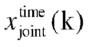


- A difference


- For example, the determination of the measurement correction matrix may be in the following identification form.
- First, an estimated value of a first output
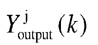


- Then the measurement correction matrix is calculated according to the calculated difference
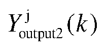


- Equations (24) and (25) herein are the second output equations of the state space equation of the battery.
- Then the posteriori value of the state vector is calculated based on the measurement correction matrix according to the priori value


- Finally, the estimated value of the SOC of the battery is calculated according to the posteriori value of the state vector and the space state equation of the battery.
- According to some embodiments of the present disclosure, the covariance of the state vectors at the previous moment is calculated according to the process noise variance, including:
- calculating a first expectation based on the first weight coefficient and the priori value of the first state vector;
- obtaining a priori value of the covariance of the state vectors based on the second weight coefficient, the difference between the priori value of the first state vector and the first expectation, and the process noise variance;
- determining an estimated value of a first output according to current data, the temperature data, the measurement noise variance, the element parameter value, and the priori value of the first state vector;
- calculating a second expectation based on the first weight coefficient and the estimated value of the first output; and
- calculating the covariance of the state vectors at the previous moment based on the measurement correction matrix, the priori value of the covariance of the state vectors, and the difference between the estimated value of the first output and the second expectation.
- For example, the first expectation



- According to some embodiments of the present disclosure, the posteriori value of the covariance of the state vectors is calculated, by using the following equation, based on the measurement correction matrix and the estimated value of the first output calculated in the above example, which is used for determining an estimated value of the SOC of the battery at a next moment.

T is a sampling interval. - According to some embodiments of the present disclosure, the process noise variance and the measurement noise variance are determined by:
- determining an output residual according to a voltage parameter in the element parameter value and the voltage data;
- calculating an output residual matrix according to a first output residual and the output residual in the estimated value of the SOC of the battery that are calculated at the previous moment;
- determining a theoretical process noise variance and a theoretical measurement noise variance according to the output residual matrix; and
- determining the process noise variance and the measurement noise variance based on a noise correction rule according to the theoretical process noise variance and the theoretical measurement noise variance.
- For example, the output residual Ue (k) of the model at the current moment may be calculated in combination with the voltage data of the battery based on a voltage output value of a battery model, as shown in Equation (27):

- In combination with the output residual within the previous moment, the output residual matrix H(k) is calculated by using Equation (28), and the theoretical noise variances Q id(k) and R id(k) are obtained according to Equation (29):


- Based on the noise correction rule, the process noise variance Q(k+1) and the measurement noise variance R(k+1) are calculated, as shown in Equation (30) and Equation (31):


- According to some embodiments of the present disclosure, the noise correction rule includes:
using the output residual at the previous moment as the process noise variance and the measurement noise variance when a value of the theoretical measurement noise variance is less than a preset threshold. - According to some embodiments of the present disclosure, after the output residual at the previous moment is used as the process noise variance and the measurement noise variance, the observer is downgraded from an AUKF observer to a UKF observer.
- A larger one of an initial value of the process noise variance and a trace of a matrix of the theoretical process noise variance is used as the process noise variance, and a larger one of an initial value of the measurement noise variance and the theoretical measurement noise variance is used as the measurement noise variance, when the value of the theoretical measurement noise variance is not less than the preset threshold.
- In
step S 13, another possible implementation is that the state data further includes temperature data, and the observer is a Luenberger observer. Accordingly, the determining an estimated value of the SOC of the battery based on the element parameter value in the equivalent circuit model, the state data, and the battery characteristic data according to a technique of an observer includes the following steps. - S1301: A priori value of a second state vector is determined according to the estimated values of the state vectors of the battery, the element parameter value, the current data, and a second state equation of a state space equation of the battery.
- S1302: An estimated value of a second output is determined according to the priori value of the second state vector, the temperature data, the current data, and the second output equation of the state space equation of the battery.
- S1303: A posteriori value of the second state vector is determined according to the estimated value of the second output, the voltage data, and a preset gain of the Luenberger observer.
- S1304: The estimated value of the SOC of the battery is determined according to the posteriori value of the second state vector and the state space equation of the battery.
- According to some embodiments of the present disclosure, after the electric vehicle is powered on, the Luenberger observer is initialized based on a battery off-line test result. In this case, estimated values of the state vectors of the battery are obtained through initialization, and the estimated values of the state vectors of the battery at other moments are calculated based on the estimated value of the SOC of the battery at the previous moment.
- For example, the expression form of the second state equation of the state space equation of the battery is as follows:

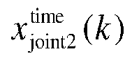
- For example, the expression form of the second output equation of the state space equation of the battery is as follows:


- For example, the posteriori value of the second state vector may be calculated by using the following equation:

- According to some embodiments of the present disclosure, the state space equation of the battery is:

- L-order RC circuits are shown in the following equation:
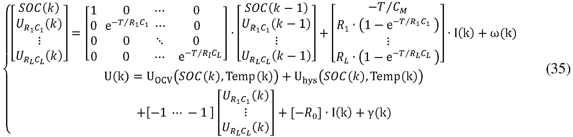
- The problem of the estimation of the SOC of a ternary lithium-ion battery produced by a certain manufacturer under a dynamic working condition is used as an example.
FIG. 6 is an effect diagram of a method for determining an SOC according to an exemplary embodiment of related arts. It can be seen that a maximum value of errors in the SOC is greater than 16%, which is difficult to satisfy the accuracy of 5% required by the BMS standard.FIG. 7 is an effect diagram of a method for determining an SOC according to an exemplary embodiment of the present disclosure. Under the same dynamic working condition, the present disclosure adopts the improved RLS and AUKF for estimation. It can be seen that the errors in the SOC are all less than 5%, which indicates that the accuracy of the present disclosure can satisfy the requirement for the accuracy of the SOC in the BMS standard. - In the above technical solution, the element parameter value in the equivalent circuit model is determined by using the RLS prediction model. In addition, in determining the element parameter value in the equivalent circuit model of the battery, the error information including at least a sampling error factor of the voltage data or a sampling error factor of the current data or the error information of the sampling error factor of the voltage data and the sampling error factor of the current data is further considered. Therefore, the impact of the sampling error may be reduced, accuracy of the element parameter value in the determined equivalent circuit model can be improved, and finally the accuracy of the determined equivalent circuit model of the battery can be improved. According to some embodiments of the present disclosure, the SOC value of the battery is determined based on the technique of the observer, so as to increase a matching degree of the element parameter value and the observer, and improve the estimation accuracy of the SOC, thereby ensuring the efficient management and the reliable operation of the vehicle.
- The present disclosure further provides an apparatus for determining an SOC of a battery. Referring to a block diagram of the apparatus for determining an equivalent circuit model shown in
FIG. 8 , theapparatus 800 includes: - an
acquisition module 810, configured to acquire state data of the battery, where the state data includes current data and voltage data; - a
first determination module 820, configured to determine each element parameter value in the equivalent circuit model of the battery based on an equivalent circuit model, error information, battery characteristic data, and the state data by using an RLS prediction model; and - a
second determination module 830, configured to determine an estimated value of the SOC of the battery based on the element parameter value in the equivalent circuit model, the state data, and the battery characteristic data according to a technique of an observer. - According to some embodiments of the present disclosure, a third determination module is configured to determine an order of the equivalent circuit model. The third determination module includes:
- an acquisition submodule, configured to obtain initial attribute information of the battery based on an off-line test of the battery, where the initial attribute information includes an OCV-SOC curve and a hysteresis voltage-SOC curve of the battery;
- an establishment submodule, configured to establish multiple initial equivalent circuit models of different orders according to the initial attribute information;
- a test submodule, configured to test, for the initial equivalent circuit model of each order, calculation error information and calculation time information of the initial equivalent circuit model under a target working condition;
- a calculation submodule, configured to calculate a matching degree of each of the initial equivalent circuit models according to a number of parameters, the calculation error information, and the calculation time information of each corresponding initial equivalent circuit model; and
- a determination submodule, configured to determine, as the equivalent circuit model of the battery, the initial equivalent circuit model having an optimal matching degree.
- According to some embodiments of the present disclosure, the equivalent circuit model is an RC circuit. The acquisition module is configured to acquire state data collected by a BMS. The state data further includes temperature data of the battery and SOC data of the battery.
- The first determination module includes:
- a first determination submodule, configured to determine, according to the SOC data, a target OCV and a target hysteresis voltage from the OCV-SOC curve and the hysteresis voltage-SOC curve of the battery that correspond to the temperature data; and
- a second determination submodule, configured to determine the element parameter value of the equivalent circuit model of the battery based on the equivalent circuit model, the error information, the current data, the voltage data, the target OCV, and the target hysteresis voltage by using the RLS prediction model.
- According to some embodiments of the present disclosure, the error information includes at least one of a sampling error factor of the voltage data, a sampling error factor of the current data, a sampling time difference between the voltage data and the current data, or an error in the OCV of the battery.
- According to some embodiments of the present disclosure, the error information includes a sampling error factor of the voltage data, a sampling error factor of the current data, a sampling time difference between the voltage data and the current data, and an error in the OCV of the battery. The identification form of the RLS prediction model is:

- Ũ(k) = U(k)± ε1, where U(k) is a truth value of a voltage of the battery at the kth moment, and ε 1 is a sampling error factor of the voltage data. Ĩ(k) = I(k+ε3)±ε2, where I is a battery current sampled synchronously with the voltage, ε 2 is a sampling error factor of the current data, and ε 3 is a sampling time difference between the current data and the voltage data. ŨOCV(k) = UOCV(k)+ε4, where ŨOCV and ε 4 respectively represent an error in an OCV value of the battery and an error in the corresponding OCV of the battery when an error exists in the SOC of the battery.
- According to some embodiments of the present disclosure, the observer is an AUKF observer. Accordingly, the second determination module includes:
- a generation submodule, configured to generate a state vector feature point set, a first weight coefficient, and a second weight coefficient according to estimated values of state vectors of the battery at a previous moment and a covariance of the state vectors, where
- the covariance of the state vectors at the previous moment is calculated according to a process noise variance;
- a fourth determination submodule, configured to calculate a priori value of a first state vector based on the element parameter value, the state vector feature point set, and the current data by using a first state equation of a state space equation of the battery;
- a fifth determination submodule, configured to determine a measurement correction matrix according to the priori value of the first state vector, a measurement noise variance, the temperature data, the current data, the first weight coefficient, the second weight coefficient, and a second output equation of the state space equation of the battery;
- a sixth determination submodule, configured to calculate a posteriori value of a second state vector based on the measurement correction matrix, the priori value of the first state vector, and the voltage data; and
- a seventh determination submodule, configured to determine the estimated value of the SOC of the battery according to the posteriori value of the second state vector and the state space equation of the battery.
- According to some embodiments of the present disclosure, the second determination module further includes:
- a first calculation submodule, configured to determine an output residual according to a voltage parameter in the element parameter value and the voltage data;
- a second calculation submodule, configured to calculate an output residual matrix according to a first output residual and the output residual in the estimated value of the SOC of the battery that are calculated at the previous moment;
- a third output submodule, configured to determine a theoretical process noise variance and a theoretical measurement noise variance according to the output residual matrix; and
- a fourth output submodule, configured to determine the process noise variance and the measurement noise variance based on a noise correction rule according to the theoretical process noise variance and the theoretical measurement noise variance.
- According to some embodiments of the present disclosure, the second determination module further includes:
- a first judging submodule, configured to use the output residual at the previous moment as the process noise variance and the measurement noise variance when a value of the theoretical measurement noise variance is less than a preset threshold; and
- a second judging submodule, configured to use a larger one of an initial value of the process noise variance and a trace of a matrix of the theoretical process noise variance as the process noise variance, and use a larger one of an initial value of the measurement noise variance and the theoretical measurement noise variance as the measurement noise variance, when the value of the theoretical measurement noise variance is not less than the preset threshold.
- According to some embodiments of the present disclosure, the observer is a Luenberger observer. Accordingly, the second determination module includes:
- a twelfth determination submodule, configured to determine a priori value of a second state vector according to the estimated values of the state vectors of the battery, the element parameter value, the current data, and a second state equation of a state space equation of the battery;
- a thirteenth determination submodule, configured to determine an estimated value of a second output according to the priori value of the second state vector, the temperature data, the current data, and the second output equation of the state space equation of the battery;
- a fourteenth determination submodule, configured to determine a posteriori value of the second state vector according to the estimated value of the second output, the voltage data, and a preset gain of the Luenberger observer; and
- a fifteenth determination submodule, configured to determine the estimated value of the SOC of the battery according to the posteriori value of the second state vector and the state space equation of the battery.
- According to some embodiments of the present disclosure, the state space equation of the battery is:

- For the apparatus in the foregoing embodiments, a specific manner in which each module performs an operation is already described in detail in the embodiments related to the method, and details are not described herein again.
- In addition, it is to be noted that, for the convenience and brevity of description, the embodiments described in the specification are all preferred embodiments, and the involved parts are not necessarily required for the present disclosure. For example, the first determination module and the second determination module may be mutually independent apparatuses or the same apparatus during specific implementation, which is not limited in the present disclosure.
- The present disclosure further provides a computer-readable storage medium, having a computer program stored thereon. The program, when executed by a processor, implements the steps of the method for determining an SOC according to any of the above embodiments.
- The present disclosure further provides an electronic device, including: a memory, having a computer program stored thereon; and
a processor, configured to execute the computer program in the memory, to implement the steps of the method for determining an SOC according to any of the above embodiments. -
FIG. 9 is a block diagram of anapparatus 900 for determining an equivalent circuit model according to an exemplary embodiment. Referring toFIG. 9 , theapparatus 900 may include one or more of the following assemblies: aprocessing assembly 902, amemory 904, apower assembly 906, amultimedia assembly 905, an input/output (I/O)interface 912, asensor assembly 914, and acommunication assembly 916. - The
processing assembly 902 is generally configured to control an overall operation of theapparatus 900, such as acquisition of data, processing of sensor data, solving of an RLS algorithm, and the like. Theprocessing assembly 902 may include one ormore processors 920 to execute instructions, to perform all or some of the steps of the above method for determining an SOC. In addition, theprocessing assembly 902 may include one or more modules, to facilitate the interaction between theprocessing assembly 902 and other assemblies. For example, theprocessing assembly 902 may include a multimedia module, to facilitate the interaction between themultimedia assembly 905 and theprocessing assembly 902. - The
memory 904 is configured to store various types of data to support operations on theapparatus 900. Examples of such data include instructions for any application or method operating on theapparatus 900, historical current data, historical voltage data, an OCV-SOC curve and a hysteresis voltage-SOC curve of a battery, and the like. Thememory 904 can be implemented by any type of volatile or non-volatile storage devices or a combination thereof, such as a static random access memory (SRAM), an electrically erasable programmable read-only memory (EEPROM), an erasable programmable read-only memory (EPROM), a programmable read-only memory (PROM), a read-only memory (ROM), a magnetic memory, a flash memory, a magnetic disk, or an optical disc. - The
power assembly 906 provides power to various assemblies of theapparatus 900. Thepower assembly 906 may include a power supply management system, one or more power supplies, and other assemblies associated with generating, managing and allocating power for theapparatus 900. - The
multimedia assembly 905 includes a screen providing an output interface between theapparatus 900 and a user. In some embodiments, the screen may include a liquid crystal display (LCD) and a touch panel (TP). If the screen includes a touch panel, the screen may be implemented as a touchscreen to receive an input signal from the user. The touch panel includes one or more touch sensors to sense touching, sliding, and gestures on the touch panel. The touch sensor may not only sense the boundary of touching or sliding operations, but also detect duration and pressure related to the touching or sliding operations. - The I/
O interface 912 provides an interface between theprocessing assembly 902 and an external interface module. The external interface module may be a click wheel, buttons, or the like. - The
sensor assembly 914 includes one or more sensors configured to provide state assessment of various aspects of theapparatus 900. For example, thesensor assembly 914 may detect a temperature, a current, and the like of the battery. In some embodiments, thesensor assembly 914 may include, for example, a temperature sensor, a speed sensor, a current sensor, and the like. - The
communication assembly 916 is configured to facilitate communication in a wired or wireless manner between theapparatus 900 and other devices. Theapparatus 900 may access a wireless network based on communication standards, such as Wi-Fi, 2G, or 3G, or a combination thereof. - In an exemplary embodiment, the
apparatus 900 can be implemented as one or more application specific integrated circuit (ASIC), a digital signal processor (DSP), a digital signal processing device (DSPD), a programmable logic device (PLD), a field programmable gate array (FPGA), a controller, a micro-controller, a microprocessor or other electronic element, so as to perform the foregoing method for determining an SOC. - In an exemplary embodiment, a non-transitory computer-readable storage medium including instructions, for example, a
memory 904 including instructions, is further provided, and the foregoing instructions may be executed by aprocessor 920 of theapparatus 900 to complete the foregoing method for determining an SOC. For example, the non-transitory computer-readable storage medium may be a ROM, a RAM, a CD-ROM, a magnetic tape, a floppy disk, an optical data storage device, or the like. - In another exemplary embodiment, a computer program product is further provided. The computer program product includes a computer program executable by a programmable apparatus. The computer program, when executed by the programmable apparatus, has a code part configured to perform the above method for determining an SOC.
- The present disclosure further provides a BMS. The BMS includes the apparatus for determining an SOC according to any of the above.
- For the battery management system in the foregoing embodiments, a specific manner in which each apparatus performs an operation is already described in detail in the embodiments related to the method, and details are not described herein again.
- The preferred implementations of the present disclosure are described in detail above with reference to the accompanying drawings. However, the present disclosure is not limited to the specific details in the foregoing implementations, a plurality of simple deformations may be made to the technical solution of the present disclosure within a range of the technical concept of the present disclosure, and these simple deformations fall within the protection scope of the present disclosure.
- It should be additionally noted that, the specific technical features described in the foregoing specific implementations may be combined in any proper manner in a case without conflict. To avoid unnecessary repetition, various possible combinations are not further described in the present disclosure.
- In addition, the various embodiments of the present disclosure may be combined without departing from the idea of the present disclosure, and such combinations shall also fall within the scope of the present disclosure.
Claims (12)
- A method for determining a state of charge (SOC) of a battery, comprising:acquiring state data of the battery, wherein the state data comprises current data and voltage data;determining each element parameter value in an equivalent circuit model of the battery based on the equivalent circuit model, error information, battery characteristic data, and the state data by using a recursive least square (RLS) prediction model; anddetermining an estimated value of the SOC of the battery based on the element parameter value in the equivalent circuit model, the state data, and the battery characteristic data according to a technique of an observer.
- The method according to claim 1, wherein the equivalent circuit model is determined by:obtaining initial attribute information of the battery based on an off-line test of the battery, wherein the initial attribute information comprises an open circuit voltage (OCV)-SOC curve and a hysteresis voltage-SOC curve of the battery;establishing a plurality of initial equivalent circuit models of different orders according to the initial attribute information;testing, for the initial equivalent circuit model of each order, calculation error information and calculation time information of the initial equivalent circuit model under a target working condition;calculating a matching degree of each of the initial equivalent circuit models according to a number of parameters, the calculation error information, and the calculation time information of each corresponding initial equivalent circuit model; anddetermining, as the equivalent circuit model of the battery, the initial equivalent circuit model having an optimal matching degree.
- The method according to claim 1 or 2, wherein the equivalent circuit model of the battery is an RC circuit model; the acquiring state data of the battery comprises:acquiring the state data collected by a battery management system (BMS), wherein the state data further comprises temperature data of the battery and SOC data of the battery; andthe determining each element parameter value in an equivalent circuit model of the battery based on the equivalent circuit model, error information, battery characteristic data, and the state data by using a recursive least square (RLS) prediction model comprises:determining, according to the SOC data, a target OCV and a target hysteresis voltage from the OCV-SOC curve and the hysteresis voltage-SOC curve of the battery that correspond to the temperature data; anddetermining the element parameter value of the equivalent circuit model of the battery based on the equivalent circuit model, the error information, the current data, the voltage data, the target OCV, and the target hysteresis voltage by using the RLS prediction model.
- The method according to claim 3, wherein the error information comprises at least one of a sampling error factor of the voltage data, a sampling error factor of the current data, a sampling time difference between the voltage data and the current data, or an error in the OCV of the battery.
- The method according to claim 3, wherein the error information comprises a sampling error factor of the voltage data, a sampling error factor of the current data, a sampling time difference between the voltage data and the current data, or an error in the OCV of the battery; an identification form of the RLS prediction model is:
 wherein Ỹ(k) is a measured value of an output signal of the RLS prediction model at a kth moment; UOCV(k) and Uhys(k) respectively represent a target OCV and a target hysteresis voltage of the battery at the kth moment; Ũ(k) is a battery voltage value collected by the BMS at the kth moment; ϕ(k) is an input signal of the RLS prediction model at the kth moment; Ĩ(k) is a battery current value collected by the BMS at the kth moment; θ(k) is a parameter matrix of the RLS prediction model at the kth moment; a 1 ~aL , a 0, c1, d0~d L , c2 are parameters in the parameter matrix; L is an order of the initial equivalent circuit model; and T is a sampling period of the BMS;Ũ(k) = U(k)±ε1; U(k) is a truth value of a voltage of the battery at the kth moment; ε 1 is a sampling error factor of the voltage data; Ĩ(k) = I(k+ε3)±ε2; I is a battery current sampled synchronously with the voltage; ε 2 is a sampling error factor of the current data; ε 3 is a sampling time difference between the current data and the voltage data; ŨOCV(k) = UOCV(k)+ε4; and ŨOCV and ε 4 respectively represent an error in an OCV value of the battery and an error in the corresponding OCV of the battery when an error exists in the SOC of the battery.
 - The method according to any of claims 1 to 5, wherein the state data further comprises temperature data; the observer is an adaptive unscented Kalman filter (AUKF) observer; the determining an estimated value of the SOC of the battery based on the element parameter value in the equivalent circuit model, the state data, and the battery characteristic data according to a technique of an observer comprises:generating a state vector feature point set, a first weight coefficient, and a second weight coefficient according to estimated values of state vectors of the battery at a previous moment and a covariance of the state vectors, wherein the covariance of the state vectors at the previous moment is calculated according to a process noise variance;calculating a priori value of a first state vector based on the element parameter value, the state vector feature point set, and the current data by using a first state equation of a state space equation of the battery;determining a measurement correction matrix according to the priori value of the first state vector, a measurement noise variance, the temperature data, the current data, the first weight coefficient, the second weight coefficient, and a second output equation of the state space equation of the battery;calculating a posteriori value of a second state vector based on the measurement correction matrix, the priori value of the first state vector, and the voltage data; anddetermining the estimated value of the SOC of the battery according to the posteriori value of the second state vector and the state space equation of the battery.
- The method according to claim 6, wherein the process noise variance and the measurement noise variance are determined by:determining an output residual according to a voltage parameter in the element parameter value and the voltage data;calculating an output residual matrix according to a first output residual and the output residual in the estimated value of the SOC of the battery that are calculated at the previous moment;determining a theoretical process noise variance and a theoretical measurement noise variance according to the output residual matrix; anddetermining the process noise variance and the measurement noise variance based on a noise correction rule according to the theoretical process noise variance and the theoretical measurement noise variance.
- The method according to claim 7, wherein the noise correction rule comprises:using the output residual at the previous moment as the process noise variance and the measurement noise variance when a value of the theoretical measurement noise variance is less than a preset threshold; andusing a larger one of an initial value of the process noise variance and a trace of a matrix of the theoretical process noise variance as the process noise variance, and using a larger one of an initial value of the measurement noise variance and the theoretical measurement noise variance as the measurement noise variance, when the value of the theoretical measurement noise variance is not less than the preset threshold.
- The method according to any of claims 1 to 8, wherein the state data further comprises the temperature data; the observer is a Luenberger observer; the determining an estimated value of the SOC of the battery based on the element parameter value in the equivalent circuit model, the state data, and the battery characteristic data according to a technique of an observer comprises:determining a priori value of a second state vector according to the estimated values of the state vectors of the battery, the element parameter value, the current data, and a second state equation of a state space equation of the battery;determining an estimated value of a second output according to the priori value of the second state vector, the temperature data, the current data, and the second output equation of the state space equation of the battery;determining a posteriori value of the second state vector according to the estimated value of the second output, the voltage data, and a preset gain of the Luenberger observer; anddetermining the estimated value of the SOC of the battery according to the posteriori value of the second state vector and the state space equation of the battery.
- The method according to any of claims 6 to 9, wherein the state space equation of the battery is:

Pparameter = [R 0, R 1 ~ RL , C 1 ~ CL ] is a column vector of the element parameter value; R 0 is an ohmic resistance of the equivalent circuit model; R 1 ~ RL are polarization resistances of the equivalent circuit model; C 1 ~ CL are polarization capacitances of the equivalent circuit model; U(k) and I(k) are respectively the voltage data and the current data at the kth moment; Temp(k) is the temperature data at the kth moment; ω(k) is the process noise; γ(k) is the measurement noise; a variance of the process noise and a variance of the measurement noise are respectively the process noise variance and the measurement noise variance; and f(•) and g(•) are both nonlinear functions. - An apparatus for determining a state of charge (SOC) of a battery, comprising:an acquisition module, configured to acquire state data of the battery, wherein the state data comprises current data and voltage data;a first determination module, configured to determine each element parameter value in an equivalent circuit model of the battery based on the equivalent circuit model, error information, battery characteristic data, and the state data by using a recursive least square (RLS) prediction model; anda second determination module, configured to determine an estimated value of the SOC of the battery based on the element parameter value in the equivalent circuit model, the state data, and the battery characteristic data according to a technique of an observer.
- A battery management system, comprising the apparatus for determining a state of charge (SOC) according to claim 11.
Applications Claiming Priority (2)
| Application Number | Priority Date | Filing Date | Title |
|---|---|---|---|
| CN202010245899.9A CN113466723B (en) | 2020-03-31 | 2020-03-31 | Method and apparatus for determining battery state of charge, battery management system |
| PCT/CN2021/080767 WO2021197038A1 (en) | 2020-03-31 | 2021-03-15 | Method and device for determining state of charge of battery, and battery management system |
Publications (2)
| Publication Number | Publication Date |
|---|---|
| EP4130769A1 true EP4130769A1 (en) | 2023-02-08 |
| EP4130769A4 EP4130769A4 (en) | 2024-04-17 |
Family
ID=77866172
Family Applications (1)
| Application Number | Title | Priority Date | Filing Date |
|---|---|---|---|
| EP21781308.8A Pending EP4130769A4 (en) | 2020-03-31 | 2021-03-15 | METHOD AND DEVICE FOR DETERMINING THE STATE OF CHARGE OF A BATTERY AND BATTERY MANAGEMENT SYSTEM |
Country Status (6)
| Country | Link |
|---|---|
| US (1) | US12607682B2 (en) |
| EP (1) | EP4130769A4 (en) |
| JP (1) | JP7848129B2 (en) |
| KR (1) | KR102750882B1 (en) |
| CN (1) | CN113466723B (en) |
| WO (1) | WO2021197038A1 (en) |
Families Citing this family (47)
| Publication number | Priority date | Publication date | Assignee | Title |
|---|---|---|---|---|
| CN112881921A (en) * | 2021-01-08 | 2021-06-01 | 恒大新能源汽车投资控股集团有限公司 | Battery equivalent circuit model parameter identification method, device, equipment and storage medium |
| JP7452508B2 (en) * | 2021-09-28 | 2024-03-19 | トヨタ自動車株式会社 | Battery diagnostic device, method, program, and vehicle |
| CN113848487A (en) * | 2021-10-22 | 2021-12-28 | 四川宽鑫科技发展有限公司 | An Equilibrium Control Method Based on Proprietary SOC Estimation |
| CN114035049B (en) * | 2021-11-08 | 2024-08-13 | 东软睿驰汽车技术(沈阳)有限公司 | SOH precision calculation method and device and electronic equipment |
| CN114091279B (en) * | 2021-11-26 | 2025-09-19 | 广东电网有限责任公司 | Lithium battery equivalent circuit model identification method, system, computing equipment and medium |
| CN114137346B (en) * | 2021-11-26 | 2023-09-12 | 国网湖南省电力有限公司 | Energy storage power station battery management system testing device based on number simulation real platform |
| CN114252771B (en) * | 2021-12-13 | 2024-05-07 | 北京经纬恒润科技股份有限公司 | A battery parameter online identification method and system |
| CN114280485B (en) * | 2021-12-27 | 2023-07-28 | 湖北亿纬动力有限公司 | SOC estimation and consistency evaluation method, device, computer equipment |
| US20230208169A1 (en) * | 2021-12-29 | 2023-06-29 | Auto Motive Power Inc. | Technique Using a Battery Charger and Battery Management System to Detect Cell Degradation and Pack Imminent Failures |
| CN114336877B (en) * | 2022-01-04 | 2025-06-06 | 一汽解放汽车有限公司 | Battery parameter identification method, device, electronic device and computer program product |
| US12394998B2 (en) | 2022-03-16 | 2025-08-19 | Joby Aero, Inc. | Nonlinear power source capability determination |
| CN114705990B (en) * | 2022-03-31 | 2023-10-20 | 上海玫克生储能科技有限公司 | Method and system for estimating battery cluster state of charge, electronic equipment and storage media |
| CN114750638B (en) * | 2022-04-07 | 2024-06-18 | 潍柴动力股份有限公司 | A power battery current control method, device, electric vehicle and storage medium |
| CN114879073B (en) * | 2022-04-22 | 2025-02-18 | 清华大学 | State of charge update method based on power characteristics of lithium-ion battery electrochemical model |
| US20230408588A1 (en) * | 2022-06-14 | 2023-12-21 | Enphase Energy, Inc. | Storage system configured for use with an energy management system |
| CN114859250B (en) * | 2022-07-07 | 2022-09-30 | 杭州华塑科技股份有限公司 | Method and device for determining state of charge information of battery and electronic equipment |
| CN115166523B (en) * | 2022-09-06 | 2022-12-02 | 江苏时代新能源科技有限公司 | Mobile battery state detection device, system and method |
| CN115792626B (en) * | 2022-11-14 | 2025-10-24 | 潍柴动力股份有限公司 | Method and device for estimating battery state of charge |
| CN115598541B (en) * | 2022-12-01 | 2023-03-10 | 西南科技大学 | Battery energy state assessment method based on forgetting factor adaptive feedback correction |
| CN115792619B (en) * | 2022-12-07 | 2026-03-06 | 昆明理工大学 | SOC estimation method, device, equipment and medium based on the charging and discharging phase of energy storage system |
| KR102881558B1 (en) * | 2022-12-09 | 2025-11-05 | 인하대학교 산학협력단 | Data based battery charge estimation method using Gaussian process |
| CN116224073A (en) * | 2023-01-18 | 2023-06-06 | 重庆长安汽车股份有限公司 | Battery SOC estimation method, device, equipment, battery module and storage medium |
| CN116224076B (en) * | 2023-03-02 | 2026-04-17 | 山东大学 | A method and system for fault diagnosis of energy storage batteries based on multi-source information fusion |
| CN116381508A (en) * | 2023-04-12 | 2023-07-04 | 广东电网有限责任公司 | A battery state of charge estimation method and system based on multi-mode fusion |
| CN116449221B (en) * | 2023-06-14 | 2023-09-29 | 浙江天能新材料有限公司 | Lithium battery state of charge prediction method, device, equipment and storage medium |
| CN116540125B (en) * | 2023-07-05 | 2023-10-03 | 中国华能集团清洁能源技术研究院有限公司 | Diagnosis method and system for battery state-of-charge estimation fault |
| CN116819343B (en) * | 2023-07-18 | 2025-09-12 | 桂林电子科技大学 | Lithium-ion battery SOC prediction method based on variable window adaptive unscented Kalman filter |
| CN117113807B (en) * | 2023-07-18 | 2024-04-05 | 广州港科大技术有限公司 | Modeling method of lithium battery SOH online prediction model based on ELM and RLS |
| CN117388741B (en) * | 2023-10-13 | 2024-05-31 | 广东云下汇金科技有限公司 | A monitoring method and system for standby generator sets in intelligent computing center |
| CN117148172B (en) * | 2023-10-31 | 2024-04-09 | 宁德时代新能源科技股份有限公司 | Battery state detection method, device, computing equipment and medium |
| CN117538764B (en) * | 2023-12-11 | 2025-03-21 | 齐鲁工业大学(山东省科学院) | A method and system for estimating state of charge of a power lithium battery |
| CN117452234B (en) * | 2023-12-22 | 2024-08-13 | 齐鲁工业大学(山东省科学院) | SOC estimation method and system for improving fusion of parameter identification and infinite algorithm |
| CN117601657B (en) * | 2024-01-19 | 2024-06-18 | 宁波均胜新能源研究院有限公司 | Battery management method and device, storage medium and vehicle |
| CN117937687B (en) * | 2024-01-29 | 2024-08-06 | 深圳市健网科技有限公司 | A SOC intelligent control method and system for a distributed energy storage system |
| CN118386940B (en) * | 2024-06-28 | 2024-12-06 | 浙江凌骁能源科技有限公司 | Power control method, device, controller, battery pack, vehicle, medium and program product |
| CN118505438B (en) * | 2024-07-17 | 2024-11-29 | 阿里云飞天(杭州)云计算技术有限公司 | Method, device, storage medium and program product for managing energy storage system |
| DE102024122349B3 (en) * | 2024-08-06 | 2025-11-13 | Dr. Ing. H.C. F. Porsche Aktiengesellschaft | Computer-implemented method for optimizing at least one parameter of at least one function for estimating an open-circuit voltage, control unit and vehicle |
| CN119087230B (en) * | 2024-09-08 | 2025-10-24 | 昆明理工大学 | State of charge estimation method for all-vanadium redox flow batteries based on adaptive observer |
| CN118858968B (en) * | 2024-09-24 | 2025-01-14 | 中汽研新能源汽车检验中心(天津)有限公司 | Battery equivalent circuit parameter identification method and system |
| CN119471167B (en) * | 2025-01-14 | 2025-07-25 | 陕西能源电力运营有限公司 | State prediction method and system for power terminal equipment |
| CN119916221B (en) * | 2025-03-31 | 2025-07-25 | 浙江吉利控股集团有限公司 | Battery SOC correction method and device, storage medium, battery device and vehicle |
| CN120595124A (en) * | 2025-06-03 | 2025-09-05 | 常州江理工技术转移中心有限公司 | A lithium battery SOP estimation optimization method |
| CN120301215B (en) * | 2025-06-06 | 2025-09-02 | 广东电网有限责任公司中山供电局 | Modularized multi-level converter current control method based on parameter identification |
| CN120409075B (en) * | 2025-07-04 | 2025-09-19 | 国网(山东)电动汽车服务有限公司 | High-precision calculation method for metering error of charging amount of charging station |
| CN120891394B (en) * | 2025-08-19 | 2026-04-17 | 张家港领声新能科技有限公司 | Battery electric quantity correction method and system based on unmanned aerial vehicle battery management system |
| CN121503376A (en) * | 2025-11-10 | 2026-02-10 | 重庆大学 | A feature-empowered method for dimensional evolutionary identification of battery parameters |
| CN121114638B (en) * | 2025-11-14 | 2026-02-13 | 湖南省银峰新能源有限公司 | Estimation method of state parameters of hybrid supercapacitor |
Family Cites Families (25)
| Publication number | Priority date | Publication date | Assignee | Title |
|---|---|---|---|---|
| JP2009134924A (en) | 2007-11-29 | 2009-06-18 | Yokogawa Electric Corp | Fuel cell characteristic evaluation method and characteristic evaluation apparatus |
| JP5379672B2 (en) | 2009-12-25 | 2013-12-25 | プライムアースEvエナジー株式会社 | Secondary battery polarization voltage calculation device and charging state estimation device |
| JP5924617B2 (en) | 2012-06-05 | 2016-05-25 | 学校法人同志社 | Equivalent circuit synthesis method and apparatus, and circuit diagnostic method |
| JP2014102111A (en) * | 2012-11-19 | 2014-06-05 | Mazda Motor Corp | State estimation device for battery |
| US9244129B2 (en) * | 2013-01-29 | 2016-01-26 | Mitsubishi Electronic Research Laboratories, Inc. | Method for estimating a state of charge of batteries |
| US10664562B2 (en) * | 2013-02-24 | 2020-05-26 | Fairchild Semiconductor Corporation and University of Connecticut | Battery state of charge tracking, equivalent circuit selection and benchmarking |
| US9575128B2 (en) * | 2013-03-12 | 2017-02-21 | GM Global Technology Operations LLC | Battery state-of-charge estimation for hybrid and electric vehicles using extended kalman filter techniques |
| CN103293485A (en) | 2013-06-10 | 2013-09-11 | 北京工业大学 | Model-based storage battery SOC (state of charge) estimating method |
| CN103439668B (en) * | 2013-09-05 | 2015-08-26 | 桂林电子科技大学 | The charge state evaluation method of power lithium-ion battery and system |
| EP2963434B1 (en) * | 2014-06-30 | 2021-08-11 | Foundation Of Soongsil University-Industry Cooperation | Battery state estimation method and system using dual extended kalman filter, and recording medium for performing the method |
| CN106154168B (en) | 2016-04-01 | 2019-03-05 | 储盈新能源科技(上海)有限公司 | The method for estimating charge state of power cell of data-driven |
| CN106019164A (en) * | 2016-07-07 | 2016-10-12 | 武汉理工大学 | Lithium battery SOC estimation algorithm based on dual adaptive unscented Kalman filter |
| CN107064811A (en) * | 2017-03-01 | 2017-08-18 | 华南理工大学 | A kind of lithium battery SOC On-line Estimation methods |
| EP3605121B1 (en) | 2017-03-31 | 2023-04-12 | Mitsubishi Electric Corporation | Storage battery state estimation device |
| CN108693472B (en) * | 2017-04-12 | 2020-11-10 | 上海蓝诺新能源技术有限公司 | Battery equivalent model parameter online identification method |
| KR102373458B1 (en) * | 2018-02-07 | 2022-03-10 | 주식회사 엘지에너지솔루션 | Method and battery management system for estimating parameters of battery equivalent circuit model for a battery |
| CN108872873A (en) | 2018-06-29 | 2018-11-23 | 长沙理工大学 | A kind of lithium iron phosphate dynamic battery state-of-charge joint estimate method based on GA-AUKF |
| FR3084170B1 (en) * | 2018-07-17 | 2020-07-17 | Zodiac Aero Electric | METHOD FOR DETERMINING A STATE NOISE COVARIANCE MATRIX FOR THE ADJUSTMENT OF A BATTERY CHARGE OBSERVER AND DEVICE THEREOF |
| CN108957347B (en) | 2018-08-13 | 2021-02-23 | 北京航空航天大学 | High-precision dynamic estimation method and system for SOC of battery pack |
| CN109783993B (en) * | 2019-03-07 | 2023-04-18 | 北京经纬恒润科技股份有限公司 | Battery equivalent model parameter determination method and device |
| CN109900937B (en) * | 2019-04-10 | 2020-12-08 | 河南科技大学 | A state-of-charge estimation method for lithium batteries with temperature compensation |
| CN110208703A (en) | 2019-04-24 | 2019-09-06 | 南京航空航天大学 | The method that compound equivalent-circuit model based on temperature adjustmemt estimates state-of-charge |
| CN110646737B (en) | 2019-09-20 | 2022-04-22 | 广州市香港科大霍英东研究院 | Battery SOC dynamic estimation method and system based on multiple models and storage medium |
| CN110888063A (en) * | 2019-12-02 | 2020-03-17 | 上海国际港务(集团)股份有限公司 | SOC estimation method based on design of port machine tire crane lithium iron phosphate battery parallel system |
| CN110780205A (en) * | 2019-12-06 | 2020-02-11 | 信息产业电子第十一设计研究院科技工程股份有限公司 | Novel iron phosphate lithium battery PNGV equivalent circuit model and parameter identification method |
-
2020
- 2020-03-31 CN CN202010245899.9A patent/CN113466723B/en active Active
-
2021
- 2021-03-15 EP EP21781308.8A patent/EP4130769A4/en active Pending
- 2021-03-15 US US17/915,308 patent/US12607682B2/en active Active
- 2021-03-15 JP JP2022556482A patent/JP7848129B2/en active Active
- 2021-03-15 WO PCT/CN2021/080767 patent/WO2021197038A1/en not_active Ceased
- 2021-03-15 KR KR1020227037040A patent/KR102750882B1/en active Active
Also Published As
| Publication number | Publication date |
|---|---|
| US20230152380A1 (en) | 2023-05-18 |
| CN113466723A (en) | 2021-10-01 |
| US12607682B2 (en) | 2026-04-21 |
| CN113466723B (en) | 2022-09-09 |
| JP7848129B2 (en) | 2026-04-20 |
| EP4130769A4 (en) | 2024-04-17 |
| JP2023518778A (en) | 2023-05-08 |
| KR20220158271A (en) | 2022-11-30 |
| KR102750882B1 (en) | 2025-01-09 |
| WO2021197038A1 (en) | 2021-10-07 |
Similar Documents
| Publication | Publication Date | Title |
|---|---|---|
| EP4130769A1 (en) | Method and device for determining state of charge of battery, and battery management system | |
| Wang et al. | A framework for state-of-charge and remaining discharge time prediction using unscented particle filter | |
| JP5058814B2 (en) | Battery state and parameter estimation system and method | |
| KR102652848B1 (en) | Method and device for determining the state of charge and health of lithium sulfur batteries | |
| US10663523B2 (en) | Remaining stored power amount estimation device, method for estimating remaining stored power amount of storage battery, and computer program | |
| CN113466725B (en) | Method and device for determining battery state of charge, storage medium and electronic device | |
| Meng et al. | Low-complexity online estimation for LiFePO4 battery state of charge in electric vehicles | |
| KR101866073B1 (en) | Method for predicting State of Health of Battery | |
| US10353007B2 (en) | Rechargeable battery parameter estimation apparatus and rechargeable battery parameter estimation method for calculating first and second coefficients which are partial derivatives of an estimated value of the battery state-of-charge | |
| JP6441913B2 (en) | Monitoring the charge stored in the battery | |
| US6534954B1 (en) | Method and apparatus for a battery state of charge estimator | |
| EP3264562B1 (en) | Method for determining an estimated combined battery state-parameter vector | |
| US10191117B2 (en) | Battery remaining power predicting device and battery pack | |
| US20160116542A1 (en) | Estimation device and estimation method | |
| Jin et al. | SOC estimation of lithium-ion battery considering the influence of discharge rate | |
| Nejad et al. | On-chip implementation of extended kalman filter for adaptive battery states monitoring | |
| JP6455914B2 (en) | Storage power remaining amount estimation device, method for estimating remaining power storage amount of storage battery, and computer program | |
| Manthopoulos et al. | A review and comparison of lithium-ion battery SOC estimation methods for electric vehicles | |
| JP4865627B2 (en) | Battery remaining capacity estimation method, battery remaining capacity estimation apparatus, and battery power supply system | |
| CN113466724B (en) | Method and device for determining parameters of battery equivalent circuit model, storage medium and electronic equipment | |
| CN115128474A (en) | Power battery SOC estimation method, system, equipment and storage medium | |
| Padalale et al. | State of charge (soc) determination through extended kalman filter in battery management systems | |
| CN117872185A (en) | Battery SOC-OCV curve generation method, device, and equipment | |
| Kadem | Real-time state of charge estimation algorithm for electrical batteries | |
| CN113466726B (en) | Method and device for determining parameters of battery equivalent circuit model, storage medium and electronic equipment |
Legal Events
| Date | Code | Title | Description |
|---|---|---|---|
| STAA | Information on the status of an ep patent application or granted ep patent |
Free format text: STATUS: THE INTERNATIONAL PUBLICATION HAS BEEN MADE |
|
| PUAI | Public reference made under article 153(3) epc to a published international application that has entered the european phase |
Free format text: ORIGINAL CODE: 0009012 |
|
| STAA | Information on the status of an ep patent application or granted ep patent |
Free format text: STATUS: REQUEST FOR EXAMINATION WAS MADE |
|
| 17P | Request for examination filed |
Effective date: 20220829 |
|
| AK | Designated contracting states |
Kind code of ref document: A1 Designated state(s): AL AT BE BG CH CY CZ DE DK EE ES FI FR GB GR HR HU IE IS IT LI LT LU LV MC MK MT NL NO PL PT RO RS SE SI SK SM TR |
|
| DAV | Request for validation of the european patent (deleted) | ||
| DAX | Request for extension of the european patent (deleted) | ||
| A4 | Supplementary search report drawn up and despatched |
Effective date: 20240318 |
|
| RIC1 | Information provided on ipc code assigned before grant |
Ipc: G01R 31/374 20190101ALN20240312BHEP Ipc: G01R 31/367 20190101ALI20240312BHEP Ipc: B60L 58/10 20190101ALI20240312BHEP Ipc: B60L 3/12 20060101ALI20240312BHEP Ipc: G01R 31/3842 20190101AFI20240312BHEP |
|
| GRAP | Despatch of communication of intention to grant a patent |
Free format text: ORIGINAL CODE: EPIDOSNIGR1 |
|
| STAA | Information on the status of an ep patent application or granted ep patent |
Free format text: STATUS: GRANT OF PATENT IS INTENDED |
|
| RIC1 | Information provided on ipc code assigned before grant |
Ipc: G01R 31/3842 20190101AFI20260112BHEP Ipc: B60L 3/12 20060101ALI20260112BHEP Ipc: B60L 58/10 20190101ALI20260112BHEP Ipc: G01R 31/367 20190101ALI20260112BHEP Ipc: G01R 31/374 20190101ALN20260112BHEP |
|
| RIC1 | Information provided on ipc code assigned before grant |
Ipc: G01R 31/3842 20190101AFI20260120BHEP Ipc: B60L 3/12 20060101ALI20260120BHEP Ipc: B60L 58/10 20190101ALI20260120BHEP Ipc: G01R 31/367 20190101ALI20260120BHEP Ipc: G01R 31/374 20190101ALN20260120BHEP |
|
| INTG | Intention to grant announced |
Effective date: 20260202 |