EP4130679B1 - Verfahren zur detektion einer phasenverschiebung in einem ausgang eines induktiven positionssensors - Google Patents
Verfahren zur detektion einer phasenverschiebung in einem ausgang eines induktiven positionssensors Download PDFInfo
- Publication number
- EP4130679B1 EP4130679B1 EP22185458.1A EP22185458A EP4130679B1 EP 4130679 B1 EP4130679 B1 EP 4130679B1 EP 22185458 A EP22185458 A EP 22185458A EP 4130679 B1 EP4130679 B1 EP 4130679B1
- Authority
- EP
- European Patent Office
- Prior art keywords
- position signal
- signal
- inductive
- phase spectrum
- phase
- Prior art date
- Legal status (The legal status is an assumption and is not a legal conclusion. Google has not performed a legal analysis and makes no representation as to the accuracy of the status listed.)
- Active
Links
Images


Classifications
-
- G—PHYSICS
- G01—MEASURING; TESTING
- G01D—MEASURING NOT SPECIALLY ADAPTED FOR A SPECIFIC VARIABLE; ARRANGEMENTS FOR MEASURING TWO OR MORE VARIABLES NOT COVERED IN A SINGLE OTHER SUBCLASS; TARIFF METERING APPARATUS; MEASURING OR TESTING NOT OTHERWISE PROVIDED FOR
- G01D5/00—Mechanical means for transferring the output of a sensing member; Means for converting the output of a sensing member to another variable where the form or nature of the sensing member does not constrain the means for converting; Transducers not specially adapted for a specific variable
- G01D5/12—Mechanical means for transferring the output of a sensing member; Means for converting the output of a sensing member to another variable where the form or nature of the sensing member does not constrain the means for converting; Transducers not specially adapted for a specific variable using electric or magnetic means
- G01D5/14—Mechanical means for transferring the output of a sensing member; Means for converting the output of a sensing member to another variable where the form or nature of the sensing member does not constrain the means for converting; Transducers not specially adapted for a specific variable using electric or magnetic means influencing the magnitude of a current or voltage
- G01D5/20—Mechanical means for transferring the output of a sensing member; Means for converting the output of a sensing member to another variable where the form or nature of the sensing member does not constrain the means for converting; Transducers not specially adapted for a specific variable using electric or magnetic means influencing the magnitude of a current or voltage by varying inductance, e.g. by a movable armature
- G01D5/204—Mechanical means for transferring the output of a sensing member; Means for converting the output of a sensing member to another variable where the form or nature of the sensing member does not constrain the means for converting; Transducers not specially adapted for a specific variable using electric or magnetic means influencing the magnitude of a current or voltage by varying inductance, e.g. by a movable armature by influencing the mutual induction between two or more coils
-
- G—PHYSICS
- G01—MEASURING; TESTING
- G01B—MEASURING LENGTH, THICKNESS OR SIMILAR LINEAR DIMENSIONS; MEASURING ANGLES; MEASURING AREAS; MEASURING IRREGULARITIES OF SURFACES OR CONTOURS
- G01B7/00—Measuring arrangements characterised by the use of electric or magnetic techniques
- G01B7/003—Measuring arrangements characterised by the use of electric or magnetic techniques for measuring position, not involving coordinate determination
-
- G—PHYSICS
- G01—MEASURING; TESTING
- G01D—MEASURING NOT SPECIALLY ADAPTED FOR A SPECIFIC VARIABLE; ARRANGEMENTS FOR MEASURING TWO OR MORE VARIABLES NOT COVERED IN A SINGLE OTHER SUBCLASS; TARIFF METERING APPARATUS; MEASURING OR TESTING NOT OTHERWISE PROVIDED FOR
- G01D3/00—Indicating or recording apparatus with provision for the special purposes referred to in the subgroups
- G01D3/08—Indicating or recording apparatus with provision for the special purposes referred to in the subgroups with provision for safeguarding the apparatus, e.g. against abnormal operation, against breakdown
-
- G—PHYSICS
- G01—MEASURING; TESTING
- G01R—MEASURING ELECTRIC VARIABLES; MEASURING MAGNETIC VARIABLES
- G01R33/00—Arrangements or instruments for measuring magnetic variables
- G01R33/0023—Electronic aspects, e.g. circuits for stimulation, evaluation, control; Treating the measured signals; calibration
- G01R33/0029—Treating the measured signals, e.g. removing offset or noise
-
- G—PHYSICS
- G01—MEASURING; TESTING
- G01D—MEASURING NOT SPECIALLY ADAPTED FOR A SPECIFIC VARIABLE; ARRANGEMENTS FOR MEASURING TWO OR MORE VARIABLES NOT COVERED IN A SINGLE OTHER SUBCLASS; TARIFF METERING APPARATUS; MEASURING OR TESTING NOT OTHERWISE PROVIDED FOR
- G01D5/00—Mechanical means for transferring the output of a sensing member; Means for converting the output of a sensing member to another variable where the form or nature of the sensing member does not constrain the means for converting; Transducers not specially adapted for a specific variable
- G01D5/12—Mechanical means for transferring the output of a sensing member; Means for converting the output of a sensing member to another variable where the form or nature of the sensing member does not constrain the means for converting; Transducers not specially adapted for a specific variable using electric or magnetic means
- G01D5/244—Mechanical means for transferring the output of a sensing member; Means for converting the output of a sensing member to another variable where the form or nature of the sensing member does not constrain the means for converting; Transducers not specially adapted for a specific variable using electric or magnetic means influencing characteristics of pulses or pulse trains; generating pulses or pulse trains
- G01D5/24457—Failure detection
- G01D5/24466—Comparison of the error value to a threshold
Definitions
- the invention relates to a method for detecting a phase shift in an output of an inductive position sensor, wherein the inductive position sensor provides a first position signal and a second phase-shifted position signal, particularly a sine position signal and a cosine position signal.
- the invention further relates to an inductive position sensor implementing the method according to the invention.
- he invention relates to a method for detecting a phase shift in an output signal of an inductive position sensor by calculating the phase spectrum of the position signal based on a Fast Fourier Transformation of the position signal and comparing the calculated phase spectrums over time to detect changes in the phase spectrums.
- Inductive position sensors implement a magnet-free technology, utilizing the physical principles of eddy currents or inductive coupling to detect the position of a target that is moving above a set of coils, consisting for example of one transmitter coil and two receiver coils, particularly a sine receiver coil and a cosine receiver coil.
- a set of coils consisting for example of one transmitter coil and two receiver coils, particularly a sine receiver coil and a cosine receiver coil.
- Such an inductive sensor system is for example disclosed in Patent Document 1.
- one transmitter coil and two receiver coils are typically provided as copper traces on a printed circuit board. They are arranged such that the transmitter coil induces a secondary voltage in the two receiver coils, which depends on the position of the conductive, e.g. metallic, target above the receiver coils. Therefore, the inductive sensor comprises or is connected to an oscillator that generates a radio-frequency signal, which is applied to the transmitter coil to create a static high frequency magnetic field. This static high frequency magnetic field is picked up by the receiver coils, particularly the sine receiver coil and the cosine receiver coil.
- the secondary voltage picked up by the receiver coils is changing in amplitude, allowing the determination of the target's position by analysing this effect.
- the target position is calculated by the arctangent of the momentary sine signal amplitude divided by the momentary cosine signal amplitude. The calculation is performed by a processing unit, which is connected to the position sensor or integral part of the position sensor.
- a complex circuit containing a demodulator, a gain stage, offset and gain mismatch compensation, an analog-to-digital converter and a digital signal processing unit providing some form of arctangent calculation is necessary.
- Patent Document 2 discloses an inductive position sensor for determining the position of a movable element.
- the position sensor comprises two subsystems, each having two transmitter units, an LC resonant circuit on the movable element and a receiver coil with an evaluation unit.
- the processing of the individual subsystems is carried out alternatively. Thus, if one subsystem is operating, all other subsystems are deactivated.
- the movable element including the LC resonant circuit rotates within a total electromagnetic field generated by the overlap of the two electromagnetic fields of the two transmitter units.
- the LC resonant circuit will produce an electromagnetic field, which will be received by the receiver coil and the evaluation unit.
- Patent Document 3 discloses a method for determining the position of a device including generating at least two, time-varying, magnetic fields using inductive elements, wherein the fields have different phases. The method further includes detecting a signal modulated on top of the fields, wherein the signal is generated from the device, and determining the position of the device based on a phase difference of the signal from the device and a reference signal. Like Patent Document 2, the disclosed method requires an LC resonant circuit on the moving device.
- Patent Document 4 discloses a sensor comprising an excitation winding, a signal generator operable to generate an excitation signal and arranged to apply the generated excitation signal to the excitation winding, a sensor winding electromagnetically coupled to the excitation winding and a signal processor operable to process a periodic electric signal generated in the sensor winding when the excitation signal is applied to the excitation winding by the signal generator to determine a value of a sensed parameter.
- the excitation signal comprises a periodic carrier signal having a first frequency modulated by a periodic modulation signal having a second frequency, the first frequency being greater than the second frequency.
- the sensor is well suited to using digital processing techniques both to generate the excitation signal and to process the signal induced in the sensor windings.
- the sensor is used to detect the relative position of two members. In other embodiments, the sensor is used to detect environmental factors such as temperature and humidity.
- Patent Document 5 discloses an inductive sensor device and a method for inductive identification comprising a first exciter inductor and a second exciter inductor extending along a measurement range and vary spatially differently from each other.
- a first inductive coupling element and a second inductive coupling element couple a signal from the two exciter inductors into a receiver inductor.
- the inductive coupling elements are formed as resonance elements with a first resonance frequency f1 and a second resonance frequency f2.
- the two exciter inductors are driven by different transmission signals S1, S2.
- Each of the transmission signals S1, S2 includes signal components of a first carrier frequency near the first resonance frequency f1 varying in temporal progression, and of a second carrier frequency near the second resonance frequency f2 varying in temporal progression.
- Patent document US 2020/341447 A1 describes determining a phase difference between two output signals of an inductive position sensor based on a Fourier transformation of these output signals.
- Errors in the position signal of an inductive position sensor result in a phase shift in the output signal of the inductive position sensor and in most cases relate to a target displacement or an electrical fault somewhere in the electronics of the inductive position sensor.
- the electronics of the inductive position sensor comprise certain safety mechanisms, so the main problem is to detect a target displacement.
- the target displacement can occur during the normal operation of the inductive position sensor or it can happen with the aging of the system including the inductive position sensor.
- the object is solved by a method for detecting a phase shift in an output signal of an inductive position sensor, as defined in claim 1, wherein the inductive position sensor provides a first position signal and a second phase-shifted position signal, particularly a sine position signal and a cosine position signal, the method comprising the steps of:
- the method according to the present invention bases on a processing of the first position signal and the second position signal.
- the processing requires sampled first position signal and second positions signal, so that in a first step the first position signal and the second position signal are sampled with a sampling frequency if the first position signal and the second position signal are analog.
- the sampling frequency is higher than frequency of the first position signal and second position signal, particularly at least 10-times or at 100-times higher.
- the Fast Fourier Transform (FFT) of the first position signal and the second position signal is calculated over one period of the inductive position sensor.
- the Fast Fourier Transform is an algorithm that computes the discrete Fourier transform (DFT) of a sequence, i.e. the sampled first position signal and the sampled second position signal.
- DFT discrete Fourier transform
- a Fourier analysis converts a signal from its original domain, usually time or space, to a representation in the frequency domain and vice versa.
- the DFT is obtained by decomposing a sequence of values into components of different frequencies.
- the calculation of the Fast Fourier Transform of the first position signal and the second position signal over one period of the inductive position sensor results in a first position vector and a second position vector, wherein the first position vector and the second position vector each comprising real components and imaginary components for each sample of the respective position signal.
- phase spectrum of the first position signal and the phase spectrum of the second position signal over one period of the inductive position sensor are calculated from the first position vector and the second position vector respectively by determining the arctan function of the imaginary part divided by the real part for each member of the first position vector and the second position vector.
- the calculated phase spectrum of the first position signal and the calculated phase spectrum of the second position signal are kept for later reference, e.g. stored in a memory of the inductive position sensor.
- the steps of sampling the first position signal and the second position signal over one period of the inductive position sensor, calculating the Fast Fourier Transform of the first position signal and the second position signal over one period of the inductive position sensor and calculating the phase spectrum of the first position signal and the phase spectrum of the second position signal over one period of the inductive position sensor from the first position vector and the second position vector are repeated for further periods of the first position signal and the second position signal of the inductive position sensor.
- the calculated phase spectrum of the first position signal and the calculated phase spectrum of the second position signal of different periods of the first position signal and the second position signal of the inductive position sensor are compared with each other to detect a change in the phase spectrum of the first position signal and/or in the phase spectrum of the second position signal.
- the calculated phase spectrum of the first position signal and/or the calculated phase spectrum of the second position signal change over time, which can be detected by the method according to the present invention.
- an aging causing a target displacement can be detected by comparing the phase spectrum of the first position signal and the second phase spectrum over multiple periods of the inductive position sensor.
- the method according to the invention can be easily implemented by digital signal processing and executed by the signal processing unit of the inductive position sensor.
- the performed calculations like the Fast Fourier Transform and phase spectrum calculations are not complex and do not require extensive memory.
- the method according to the invention can executed by the signal processing unit of common inductive position sensors, particularly in real time.
- the initially calculated phase spectrum of the first position signal and the initially calculated phase spectrum of the second position signal are stored as first initial phase spectrum and second initial phase spectrum and all afterwards calculated phase spectrums for the first position signal and the second position signal are compared to the first initial phase spectrum respectively second initial phase spectrum.
- the step of calculating the phase spectrum of the first position signal and the phase spectrum of the second position signal over one period of the inductive position sensor from the first position vector and the second position vector further comprises the step of detecting the maximum value for the phase spectrum of the first position signal and maximum value for the phase spectrum of the second position signal.
- the maximum values for the phase spectrum of the first position signal and the maximum values of the phase spectrum of the second position signal of different periods of the first position signal and the second position signal of the inductive position sensor are compared to each other to detect a change in the phase spectrum of the first position signal and/or in the phase spectrum of the second position signal.
- the method according to the invention focus on the maximum values of the phase spectrums of the first position signal and second position signal, which reduces the computational effort.
- the method further comprises the steps of calculating the difference between the phase spectrum of the first position signal and the phase spectrum of the second position signal for different periods of the inductive position sensor and comparing the difference between the phase spectrum of the first position signal and the phase spectrum of the second position signal for different periods of the inductive position sensor. For each period of the first position signal and the second position signal of the inductive position sensor the difference between the phase spectrum of the first position signal and the phase spectrum of the second position signal is calculated. This is repeated for following periods of the first position signal and the second position signal of the inductive position sensor and the results are compared to the first and preferably to all previously calculated differences between the phase spectrum of the first position signal and the phase spectrum of the second position signal. Thereby, errors relating to a phase shift between the first position signal and the second position channel, or generally between different channels of the inductive position sensor, can be detected.
- the method comprises the step of issuing a warning to a system connected to the inductive position sensor if the phase spectrum of the first position signal and/or the phase spectrum of the second position signal and/or the difference between the phase spectrum of the first position signal and the phase spectrum of the second position signal for different periods of the first position signal and the second position signal of the inductive position sensor exceeds an error level.
- the error level is for example 0.1 % full scale or 3° or 4° phase shift between the first position signal and the second position signal.
- the method comprises the step of filtering the calculated phase spectrum of the first position signal and of the phase spectrum of the second position signal to filter out other harmonics relating to noise.
- the calculated phase spectrums are noisy due to the division calculations involved.
- a solution is achieved by defining a certain threshold and ignore all other components that come from the noise, i.e. filtering out harmonics related to noise.
- the method further comprises the steps of receiving an external reference signal for the first position signal and/or the second position signal defining the starting position of the respective the first position signal and/or the second position signal and comparing the calculated phase spectrum of the first position signal and/or the phase spectrum of the second position signal at the starting position with the received external reference signal for the first position signal and/or the second position signal. If the starting point of the first position signal and/or the second position signal is detected by an external reference like a mechanical switch, the calculated phase spectrum at this point should always be the same. For example, the phase of a first sine position signal should at the starting point always be 0°, while the phase of a second cosine position signal at the starting point should be 90°. Whenever this is no longer the case, the sensor performance degraded or there is an issue on the mechanics of the inductive position sensor, as for example a target displacement.
- the starting position of a sine position signal has a zero amplitude or 0° and the starting position of a cosine position has a maximum amplitude of the cosine position signal or 90°.
- the method further comprises the step of storing a history, a gradient, a distribution and/or a trend of the calculated the phase spectrums of the first position signal and the phase spectrums of the second position signal over multiple periods of the inductive position sensor.
- the behavior of the inductive position sensor can be further analyzed for example it can be predicted based on this behavior how the inductive position sensor will behave in the future.
- an inductive position sensor providing a first position signal and a second phase-shifted position signal, particularly a sine position signal and a cosine position signal, wherein the inductive position sensor comprises a processing unit implementing the method according to the invention.
- the conductive target can be any kind of metal, such as aluminium, steel or a printed circuit board with a printed copper layer.
- an inductive position sensor comprises a metallic target.
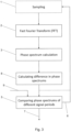
- Fig. 1 shows a flow diagram of a first embodiment of a method for detecting a phase shift in an output signal of an inductive position sensor according to the invention.
- the inductive position sensor provides a first position signal and a second phase-shifted position signal, particularly a sine position signal and a cosine position signal.
- a first optional step of the method according to the invention the first position signal and the second position signal are sampled 1 over one period of the inductive position sensor with a sampling frequency. Since this step is optional, it is shown in Fig. Fig. 1 in a dashed box. This step can be omitted if the inductive position sensor provides a series of discrete values, i.e. a sampled first positions signals and second position signals. If the first position signal and the second position signal are analog, the sampling 1 step is necessary.
- the Fast Fourier Transform is calculated 2 of the first (sampled) position signal and the second (sampled) position signal over one period of the inductive position sensor.
- This calculation 2 of the FFT results in a first position vector comprising real components and imaginary components for each sample of the first (sampled) position signal and in a second position vector comprising real components and imaginary components for each sample of the second (sampled) position signal.
- phase spectrum of the first position signal is calculated 3 over one period of the inductive position sensor from the first position vector by determining the arctan function of the imaginary part divided by the real part for each member of the first position vector.
- phase spectrum of the second position signal is calculated 3 over one period of the inductive position sensor from the second position vector by determining the arctan function of the imaginary part divided by the real part for each member of the second position vector.
- a further optional step of the method according to the invention is the filtering 4 of the calculated phase spectrum of the first position signal and of the phase spectrum of the second position signal to filter out other harmonics relating to noise.
- the initially calculated 3 phase spectrum of the first position signal and the initially calculated 3 phase spectrum of the second position signal are stored as first initial phase spectrum and second initial phase spectrum.
- the method according to the invention repeats the previous steps for future periods of the position signal of the inductive position sensor.
- the method according to the invention comprises the step of comparing 5 the calculated 3 phase spectrum of the first position signal and the phase spectrum of the second position signal of different periods of the first position signal and the second position signal of the inductive position sensor to detect a change in the phase spectrum of the first position signal and/or in the phase spectrum of the second position signal.
- the method according to the invention issues 7 a warning to a system connected to the inductive position sensor if the phase spectrum of the first position signal and/or the phase spectrum of the second position signal for different periods of the first position signal and the second position signal of the inductive position sensor exceeds an error level.
- a a warning can be issued 7 to a system connected to the inductive position sensor if the difference between the phase spectrum of the first position signal and the phase spectrum of the second position signal for different periods of the first position signal and the second position signal of the inductive position sensor exceeds an error level.
Landscapes
- Physics & Mathematics (AREA)
- General Physics & Mathematics (AREA)
- Condensed Matter Physics & Semiconductors (AREA)
- Transmission And Conversion Of Sensor Element Output (AREA)
Claims (10)
- Verfahren zum Detektieren einer Phasenverschiebung in einem Ausgangssignal eines induktiven Positionssensors, wobei der induktive Positionssensor ein erstes Positionssignal und ein zweites phasenverschobenes Positionssignal, insbesondere ein Sinus-Positionssignal und ein Cosinus-Positionssignal, bereitstellt, wobei das Verfahren die folgenden Schritte umfasst:Abtasten (1) des ersten Positionssignals und des zweiten Positionssignals über eine Periode des induktiven Positionssensors mit einer Abtastfrequenz, wenn das erste Positionssignal und das zweite Positionssignal analog sind;Berechnen (2) der Fast-Fourier-Transformation des ersten Positionssignals und des zweiten Positionssignals über eine Periode des induktiven Positionssensors, was in einem ersten Positionsvektor und einem zweiten Positionsvektor resultiert, wobei der erste Positionsvektor und der zweite Positionsvektor jeweils reale Komponenten und imaginäre Komponenten für jede Abtastung des jeweiligen Positionssignals umfassen;Berechnen (3) des Phasenspektrums des ersten Positionssignals und des Phasenspektrums des zweiten Positionssignals über eine Periode des induktiven Positionssensors aus dem ersten Positionsvektor und dem zweiten Positionsvektor durch Bestimmen der Arctan-Funktion des Imaginärteils geteilt durch den Realteil für jedes Element des ersten Positionsvektors und des zweiten Positionsvektors;Wiederholen (6) der Schritte des Abtastens (1) des ersten Positionssignals und des zweiten Positionssignals über eine Periode des induktiven Positionssensors, Berechnen (2) der Fast-Fourier-Transformation des ersten Positionssignals unddes zweiten Positionssignals über eine Periode des induktiven Positionssensors und Berechnen (3) des Phasenspektrums des ersten Positionssignals und des Phasenspektrums des zweiten Positionssignals über eine Periode des induktiven Positionssensors aus dem ersten Positionsvektor und dem zweiten Positionsvektor für weitere Perioden des ersten Positionssignals und des zweiten Positionssignals des induktiven Positionssensors ,Vergleichen (5) des berechneten (3) Phasenspektrums des ersten Positionssignals und des Phasenspektrums des zweiten Positionssignals verschiedener Perioden des ersten Positionssignals und des zweiten Positionssignals des induktiven Positionssensors, um eine Änderung im Phasenspektrum des ersten Positionssignals und/oder im Phasenspektrum des zweiten Positionssignals zu erkennen,wobei das anfänglich berechnete (3) Phasenspektrum des ersten Positionssignals und das anfänglich berechnete (3) Phasenspektrum des zweiten Positionssignals als erstes Anfangsphasenspektrum und zweites Anfangsphasenspektrum gespeichert werden und alle danach berechneten (3) Phasenspektren für das erste Positionssignal und das zweite Positionssignal mit dem ersten Anfangsphasenspektrum bzw. zweiten Anfangsphasenspektrum verglichen werden (5).
- Verfahren zum Detektieren einer Phasenverschiebung in einem Ausgangssignal eines induktiven Positionssensors nach Anspruch 1,
wobei der Schritt des Berechnens (3) des Phasenspektrums des ersten Positionssignals und des Phasenspektrums des zweiten Positionssignals über eine Periode des induktiven Positionssensors aus dem ersten Positionsvektor und dem zweiten Positionsvektor ferner den Schritt des Erfassens des Maximalwertes für das Phasenspektrum des ersten Positionssignals und des Maximalwertes für das Phasenspektrum des zweiten Positionssignals umfasst. - Verfahren zum Detektieren einer Phasenverschiebung in einem Ausgangssignal eines induktiven Positionssensors nach Anspruch 2,
wobei die Maximalwerte für das Phasenspektrum des ersten Positionssignals und die Maximalwerte des Phasenspektrums des zweiten Positionssignals verschiedener Perioden des ersten Positionssignals und des zweiten Positionssignals des induktiven Positionssensors miteinander verglichen werden (5), um eine Änderung im Phasenspektrum des ersten Positionssignals und/oder im Phasenspektrum des zweiten Positionssignals zu erkennen. - Verfahren zum Detektieren einer Phasenverschiebung in einem Ausgangssignal eines induktiven Positionssensors nach einem der Ansprüche 1 bis 3,ferner umfassend die Schritte Berechnen (8) der Differenz zwischen dem Phasenspektrum des ersten Positionssignals und dem Phasenspektrum des zweiten Positionssignals für verschiedene Perioden des induktiven Positionssensors undVergleichen (5) der Differenz zwischen dem Phasenspektrum des ersten Positionssignals und dem Phasenspektrum des zweiten Positionssignals für verschiedene Perioden des induktiven Positionssensors.
- Verfahren zum Detektieren einer Phasenverschiebung in einem Ausgangssignal eines induktiven Positionssensors nach einem der Ansprüche 1 bis 4,
ferner umfassend den Schritt Ausgeben (7) einer Warnung an ein mit dem induktiven Positionssensor verbundenes System, wenn das Phasenspektrum des ersten Positionssignals und/oder das Phasenspektrum des zweiten Positionssignals und/oder die Differenz zwischen dem Phasenspektrum des ersten Positionssignals und dem Phasenspektrum des zweiten Positionssignals für verschiedene Perioden des ersten Positionssignals und des zweiten Positionssignals des induktiven Positionssensors einen Fehlerpegel überschreitet. - Verfahren zum Detektieren einer Phasenverschiebung in einem Ausgangssignal eines induktiven Positionssensors nach einem der Ansprüche 1 bis 5,
ferner umfassend den Schritt Filtern (4) des berechneten (3) Phasenspektrums des ersten Positionssignals und des Phasenspektrums des zweiten Positionssignals, um andere Oberschwingungen, die mit Rauschen zusammenhängen, herauszufiltern. - Verfahren zum Detektieren einer Phasenverschiebung in einem Ausgangssignal eines induktiven Positionssensors nach einem der Ansprüche 1 bis 6,ferner umfassend die Schritte Empfangen (9) eines externen Referenzsignals für das erste Positionssignal und/oder das zweite Positionssignal, das die Startposition des jeweiligen ersten Positionssignals und/oder zweiten Positionssignals definiert, undVergleichen (5) des berechneten (4) Phasenspektrums des ersten Positionssignals und/oder des Phasenspektrums des zweiten Positionssignals an der Startposition mit dem empfangenen (9) externen Referenzsignal für das erste Positionssignal und/oder das zweite Positionssignal.
- Verfahren zum Detektieren einer Phasenverschiebung in einem Ausgangssignal eines induktiven Positionssensors nach Anspruch 7,
wobei die Startposition eines Sinuspositionssignals eine Nullamplitude oder 0° und die Startposition einer Kosinusposition eine maximale Amplitude des Kosinuspositionssignals oder 90° hat. - Verfahren zum Detektieren einer Phasenverschiebung in einem Ausgangssignal eines induktiven Positionssensors nach einem der Ansprüche 1 bis 8,
ferner umfassend den Schritt Speichern einer Historie, eines Gradienten, einer Verteilung und/oder eines Trends der berechneten Phasenspektren des ersten Positionssignals und der Phasenspektren des zweiten Positionssignals über mehrere Perioden des induktiven Positionssensors. - Induktiver Positionssensor, der ein erstes Positionssignal und ein zweites phasenverschobenes Positionssignal, insbesondere ein Sinus-Positionssignal und ein Cosinus-Positionssignal, bereitstellt, wobei der induktive Positionssensor eine Verarbeitungseinheit umfasst, die so konfiguriert ist, dass sie das Verfahren nach einem der Ansprüche 1 bis 9 implementiert.
Priority Applications (1)
| Application Number | Priority Date | Filing Date | Title |
|---|---|---|---|
| US17/872,269 US12013236B2 (en) | 2021-08-02 | 2022-07-25 | Method for detecting a phase shift in an output of an inductive position sensor |
Applications Claiming Priority (1)
| Application Number | Priority Date | Filing Date | Title |
|---|---|---|---|
| US202163228341P | 2021-08-02 | 2021-08-02 |
Publications (2)
| Publication Number | Publication Date |
|---|---|
| EP4130679A1 EP4130679A1 (de) | 2023-02-08 |
| EP4130679B1 true EP4130679B1 (de) | 2025-03-19 |
Family
ID=82655159
Family Applications (1)
| Application Number | Title | Priority Date | Filing Date |
|---|---|---|---|
| EP22185458.1A Active EP4130679B1 (de) | 2021-08-02 | 2022-07-18 | Verfahren zur detektion einer phasenverschiebung in einem ausgang eines induktiven positionssensors |
Country Status (2)
| Country | Link |
|---|---|
| US (1) | US12013236B2 (de) |
| EP (1) | EP4130679B1 (de) |
Family Cites Families (9)
| Publication number | Priority date | Publication date | Assignee | Title |
|---|---|---|---|---|
| IE55855B1 (en) | 1984-10-19 | 1991-01-30 | Kollmorgen Ireland Ltd | Position and speed sensors |
| GB0126014D0 (en) | 2001-10-30 | 2001-12-19 | Sensopad Technologies Ltd | Modulated field position sensor |
| US7045996B2 (en) | 2003-01-30 | 2006-05-16 | Hewlett-Packard Development Company, L.P. | Position determination based on phase difference |
| US6934665B2 (en) * | 2003-10-22 | 2005-08-23 | Motorola, Inc. | Electronic sensor with signal conditioning |
| DE102006055409A1 (de) | 2006-11-22 | 2008-05-29 | Ab Elektronik Gmbh | Induktiver Sensor zur Erfassung von zwei Koppelelementen |
| JP5041419B2 (ja) * | 2007-12-28 | 2012-10-03 | 東芝機械株式会社 | レゾルバ装置およびレゾルバの角度検出装置とその方法 |
| ES2553890T3 (es) | 2008-03-26 | 2015-12-14 | Elmos Semiconductor Ag | Sensor de posición inductivo |
| US20190212171A1 (en) * | 2018-01-08 | 2019-07-11 | Raytheon Company | Inductive sensor with digital demodulation |
| JP7161439B2 (ja) * | 2019-04-23 | 2022-10-26 | ルネサスエレクトロニクス株式会社 | 半導体装置及びモータ制御システム |
-
2022
- 2022-07-18 EP EP22185458.1A patent/EP4130679B1/de active Active
- 2022-07-25 US US17/872,269 patent/US12013236B2/en active Active
Also Published As
| Publication number | Publication date |
|---|---|
| US20230034557A1 (en) | 2023-02-02 |
| EP4130679A1 (de) | 2023-02-08 |
| US12013236B2 (en) | 2024-06-18 |
Similar Documents
| Publication | Publication Date | Title |
|---|---|---|
| EP3062076B1 (de) | Temperaturerfassungsvorrichtung und drehwinkelerfassungsvorrichtung | |
| Sarikhani et al. | Inter-turn fault detection in PM synchronous machines by physics-based back electromotive force estimation | |
| CN115698662B (zh) | 扭矩传感装置 | |
| US6498409B1 (en) | Tachometer apparatus and method for motor velocity measurement | |
| EP2965419B1 (de) | Motorregelung für eine servolenkung | |
| JP2018531392A (ja) | 回転角度センサ | |
| EP4184123A1 (de) | Radialer induktiver positionssensor zur erfassung einer drehbewegung, hochauflösendes positionssensorsystem und drehmomentsensorsystem | |
| WO2014195424A1 (en) | Rotary encoder | |
| Im et al. | Proposing new planar-type search coil for permanent magnet synchronous motor: Design and application for position estimation | |
| EP1249693A2 (de) | Apparat zur Erfassung einer relativen Winkelpositionsänderung | |
| EP4130679B1 (de) | Verfahren zur detektion einer phasenverschiebung in einem ausgang eines induktiven positionssensors | |
| US20100244817A1 (en) | Resolver | |
| US12044555B2 (en) | Displacement detection device | |
| EP4293322A1 (de) | Induktiver positionssensor zum detektieren einer linearen oder dreh- bewegung eines leitfähigen targets | |
| US12332091B2 (en) | Control device of rotation detector | |
| CN117928609A (zh) | 用于感应式位置传感器的信号处理单元 | |
| US20120209562A1 (en) | Assembly and method for determining an angular position | |
| Aung | Analysis and synthesis of precision resolver system | |
| Hoßfeld et al. | A Method for Disturbance-Tolerant “Sensorless” Angle Measurement of DC Motors | |
| EP4209758B1 (de) | Induktiver positionssensor und verfahren zur detektion der bewegung eines leitenden gebers | |
| US12235137B2 (en) | Position detection by an inductive position sensor | |
| EP4163600B1 (de) | Verfahren zur fehlererkennung eines positionssensors sowie positionssensor | |
| WO2020223329A1 (en) | Method and device for detection of condition of brushless motors and generators | |
| CN118111320A (zh) | 感应式传感器设备 | |
| US20170234904A1 (en) | Speed sensor |
Legal Events
| Date | Code | Title | Description |
|---|---|---|---|
| PUAI | Public reference made under article 153(3) epc to a published international application that has entered the european phase |
Free format text: ORIGINAL CODE: 0009012 |
|
| STAA | Information on the status of an ep patent application or granted ep patent |
Free format text: STATUS: THE APPLICATION HAS BEEN PUBLISHED |
|
| AK | Designated contracting states |
Kind code of ref document: A1 Designated state(s): AL AT BE BG CH CY CZ DE DK EE ES FI FR GB GR HR HU IE IS IT LI LT LU LV MC MK MT NL NO PL PT RO RS SE SI SK SM TR |
|
| STAA | Information on the status of an ep patent application or granted ep patent |
Free format text: STATUS: REQUEST FOR EXAMINATION WAS MADE |
|
| 17P | Request for examination filed |
Effective date: 20230717 |
|
| RBV | Designated contracting states (corrected) |
Designated state(s): AL AT BE BG CH CY CZ DE DK EE ES FI FR GB GR HR HU IE IS IT LI LT LU LV MC MK MT NL NO PL PT RO RS SE SI SK SM TR |
|
| GRAP | Despatch of communication of intention to grant a patent |
Free format text: ORIGINAL CODE: EPIDOSNIGR1 |
|
| STAA | Information on the status of an ep patent application or granted ep patent |
Free format text: STATUS: GRANT OF PATENT IS INTENDED |
|
| RIC1 | Information provided on ipc code assigned before grant |
Ipc: G01D 5/244 20060101ALN20241115BHEP Ipc: G01D 5/20 20060101ALI20241115BHEP Ipc: G01D 3/08 20060101AFI20241115BHEP |
|
| INTG | Intention to grant announced |
Effective date: 20241203 |
|
| GRAS | Grant fee paid |
Free format text: ORIGINAL CODE: EPIDOSNIGR3 |
|
| GRAA | (expected) grant |
Free format text: ORIGINAL CODE: 0009210 |
|
| STAA | Information on the status of an ep patent application or granted ep patent |
Free format text: STATUS: THE PATENT HAS BEEN GRANTED |
|
| AK | Designated contracting states |
Kind code of ref document: B1 Designated state(s): AL AT BE BG CH CY CZ DE DK EE ES FI FR GB GR HR HU IE IS IT LI LT LU LV MC MK MT NL NO PL PT RO RS SE SI SK SM TR |
|
| REG | Reference to a national code |
Ref country code: GB Ref legal event code: FG4D |
|
| REG | Reference to a national code |
Ref country code: CH Ref legal event code: EP |
|
| REG | Reference to a national code |
Ref country code: DE Ref legal event code: R096 Ref document number: 602022011886 Country of ref document: DE |
|
| REG | Reference to a national code |
Ref country code: IE Ref legal event code: FG4D |
|
| PG25 | Lapsed in a contracting state [announced via postgrant information from national office to epo] |
Ref country code: RS Free format text: LAPSE BECAUSE OF FAILURE TO SUBMIT A TRANSLATION OF THE DESCRIPTION OR TO PAY THE FEE WITHIN THE PRESCRIBED TIME-LIMIT Effective date: 20250619 |
|
| PG25 | Lapsed in a contracting state [announced via postgrant information from national office to epo] |
Ref country code: FI Free format text: LAPSE BECAUSE OF FAILURE TO SUBMIT A TRANSLATION OF THE DESCRIPTION OR TO PAY THE FEE WITHIN THE PRESCRIBED TIME-LIMIT Effective date: 20250319 |
|
| REG | Reference to a national code |
Ref country code: LT Ref legal event code: MG9D |
|
| PG25 | Lapsed in a contracting state [announced via postgrant information from national office to epo] |
Ref country code: NO Free format text: LAPSE BECAUSE OF FAILURE TO SUBMIT A TRANSLATION OF THE DESCRIPTION OR TO PAY THE FEE WITHIN THE PRESCRIBED TIME-LIMIT Effective date: 20250619 |
|
| PG25 | Lapsed in a contracting state [announced via postgrant information from national office to epo] |
Ref country code: HR Free format text: LAPSE BECAUSE OF FAILURE TO SUBMIT A TRANSLATION OF THE DESCRIPTION OR TO PAY THE FEE WITHIN THE PRESCRIBED TIME-LIMIT Effective date: 20250319 |
|
| PG25 | Lapsed in a contracting state [announced via postgrant information from national office to epo] |
Ref country code: LV Free format text: LAPSE BECAUSE OF FAILURE TO SUBMIT A TRANSLATION OF THE DESCRIPTION OR TO PAY THE FEE WITHIN THE PRESCRIBED TIME-LIMIT Effective date: 20250319 |
|
| PG25 | Lapsed in a contracting state [announced via postgrant information from national office to epo] |
Ref country code: GR Free format text: LAPSE BECAUSE OF FAILURE TO SUBMIT A TRANSLATION OF THE DESCRIPTION OR TO PAY THE FEE WITHIN THE PRESCRIBED TIME-LIMIT Effective date: 20250620 Ref country code: BG Free format text: LAPSE BECAUSE OF FAILURE TO SUBMIT A TRANSLATION OF THE DESCRIPTION OR TO PAY THE FEE WITHIN THE PRESCRIBED TIME-LIMIT Effective date: 20250319 |
|
| REG | Reference to a national code |
Ref country code: NL Ref legal event code: MP Effective date: 20250319 |
|
| REG | Reference to a national code |
Ref country code: AT Ref legal event code: MK05 Ref document number: 1777274 Country of ref document: AT Kind code of ref document: T Effective date: 20250319 |
|
| PG25 | Lapsed in a contracting state [announced via postgrant information from national office to epo] |
Ref country code: NL Free format text: LAPSE BECAUSE OF FAILURE TO SUBMIT A TRANSLATION OF THE DESCRIPTION OR TO PAY THE FEE WITHIN THE PRESCRIBED TIME-LIMIT Effective date: 20250319 |
|
| PG25 | Lapsed in a contracting state [announced via postgrant information from national office to epo] |
Ref country code: SE Free format text: LAPSE BECAUSE OF FAILURE TO SUBMIT A TRANSLATION OF THE DESCRIPTION OR TO PAY THE FEE WITHIN THE PRESCRIBED TIME-LIMIT Effective date: 20250319 |
|
| PG25 | Lapsed in a contracting state [announced via postgrant information from national office to epo] |
Ref country code: SM Free format text: LAPSE BECAUSE OF FAILURE TO SUBMIT A TRANSLATION OF THE DESCRIPTION OR TO PAY THE FEE WITHIN THE PRESCRIBED TIME-LIMIT Effective date: 20250319 |
|
| PG25 | Lapsed in a contracting state [announced via postgrant information from national office to epo] |
Ref country code: ES Free format text: LAPSE BECAUSE OF FAILURE TO SUBMIT A TRANSLATION OF THE DESCRIPTION OR TO PAY THE FEE WITHIN THE PRESCRIBED TIME-LIMIT Effective date: 20250319 Ref country code: PT Free format text: LAPSE BECAUSE OF FAILURE TO SUBMIT A TRANSLATION OF THE DESCRIPTION OR TO PAY THE FEE WITHIN THE PRESCRIBED TIME-LIMIT Effective date: 20250721 |
|
| PGFP | Annual fee paid to national office [announced via postgrant information from national office to epo] |
Ref country code: DE Payment date: 20250728 Year of fee payment: 4 |
|
| PG25 | Lapsed in a contracting state [announced via postgrant information from national office to epo] |
Ref country code: IT Free format text: LAPSE BECAUSE OF FAILURE TO SUBMIT A TRANSLATION OF THE DESCRIPTION OR TO PAY THE FEE WITHIN THE PRESCRIBED TIME-LIMIT Effective date: 20250319 Ref country code: PL Free format text: LAPSE BECAUSE OF FAILURE TO SUBMIT A TRANSLATION OF THE DESCRIPTION OR TO PAY THE FEE WITHIN THE PRESCRIBED TIME-LIMIT Effective date: 20250319 |
|
| PG25 | Lapsed in a contracting state [announced via postgrant information from national office to epo] |
Ref country code: AT Free format text: LAPSE BECAUSE OF FAILURE TO SUBMIT A TRANSLATION OF THE DESCRIPTION OR TO PAY THE FEE WITHIN THE PRESCRIBED TIME-LIMIT Effective date: 20250319 |
|
| PG25 | Lapsed in a contracting state [announced via postgrant information from national office to epo] |
Ref country code: CZ Free format text: LAPSE BECAUSE OF FAILURE TO SUBMIT A TRANSLATION OF THE DESCRIPTION OR TO PAY THE FEE WITHIN THE PRESCRIBED TIME-LIMIT Effective date: 20250319 Ref country code: EE Free format text: LAPSE BECAUSE OF FAILURE TO SUBMIT A TRANSLATION OF THE DESCRIPTION OR TO PAY THE FEE WITHIN THE PRESCRIBED TIME-LIMIT Effective date: 20250319 |
|
| PG25 | Lapsed in a contracting state [announced via postgrant information from national office to epo] |
Ref country code: RO Free format text: LAPSE BECAUSE OF FAILURE TO SUBMIT A TRANSLATION OF THE DESCRIPTION OR TO PAY THE FEE WITHIN THE PRESCRIBED TIME-LIMIT Effective date: 20250319 |
|
| PG25 | Lapsed in a contracting state [announced via postgrant information from national office to epo] |
Ref country code: SK Free format text: LAPSE BECAUSE OF FAILURE TO SUBMIT A TRANSLATION OF THE DESCRIPTION OR TO PAY THE FEE WITHIN THE PRESCRIBED TIME-LIMIT Effective date: 20250319 |
|
| PG25 | Lapsed in a contracting state [announced via postgrant information from national office to epo] |
Ref country code: IS Free format text: LAPSE BECAUSE OF FAILURE TO SUBMIT A TRANSLATION OF THE DESCRIPTION OR TO PAY THE FEE WITHIN THE PRESCRIBED TIME-LIMIT Effective date: 20250719 |