EP4130633A1 - Heat exchanger, refrigeration cycle device, and method for manufacturing heat exchanger - Google Patents
Heat exchanger, refrigeration cycle device, and method for manufacturing heat exchanger Download PDFInfo
- Publication number
- EP4130633A1 EP4130633A1 EP20926879.6A EP20926879A EP4130633A1 EP 4130633 A1 EP4130633 A1 EP 4130633A1 EP 20926879 A EP20926879 A EP 20926879A EP 4130633 A1 EP4130633 A1 EP 4130633A1
- Authority
- EP
- European Patent Office
- Prior art keywords
- heat transfer
- fin
- transfer tube
- heat exchanger
- heat
- Prior art date
- Legal status (The legal status is an assumption and is not a legal conclusion. Google has not performed a legal analysis and makes no representation as to the accuracy of the status listed.)
- Withdrawn
Links
Images







Classifications
-
- F—MECHANICAL ENGINEERING; LIGHTING; HEATING; WEAPONS; BLASTING
- F28—HEAT EXCHANGE IN GENERAL
- F28F—DETAILS OF HEAT-EXCHANGE AND HEAT-TRANSFER APPARATUS, OF GENERAL APPLICATION
- F28F1/00—Tubular elements; Assemblies of tubular elements
- F28F1/10—Tubular elements and assemblies thereof with means for increasing heat-transfer area, e.g. with fins, with projections, with recesses
- F28F1/12—Tubular elements and assemblies thereof with means for increasing heat-transfer area, e.g. with fins, with projections, with recesses the means being only outside the tubular element
- F28F1/14—Tubular elements and assemblies thereof with means for increasing heat-transfer area, e.g. with fins, with projections, with recesses the means being only outside the tubular element and extending longitudinally
- F28F1/16—Tubular elements and assemblies thereof with means for increasing heat-transfer area, e.g. with fins, with projections, with recesses the means being only outside the tubular element and extending longitudinally the means being integral with the element, e.g. formed by extrusion
-
- B—PERFORMING OPERATIONS; TRANSPORTING
- B21—MECHANICAL METAL-WORKING WITHOUT ESSENTIALLY REMOVING MATERIAL; PUNCHING METAL
- B21C—MANUFACTURE OF METAL SHEETS, WIRE, RODS, TUBES, PROFILES OR LIKE SEMI-MANUFACTURED PRODUCTS OTHERWISE THAN BY ROLLING; AUXILIARY OPERATIONS USED IN CONNECTION WITH METAL-WORKING WITHOUT ESSENTIALLY REMOVING MATERIAL
- B21C23/00—Extruding metal; Impact extrusion
- B21C23/02—Making uncoated products
- B21C23/04—Making uncoated products by direct extrusion
- B21C23/08—Making wire, rods or tubes
- B21C23/085—Making tubes
-
- B—PERFORMING OPERATIONS; TRANSPORTING
- B21—MECHANICAL METAL-WORKING WITHOUT ESSENTIALLY REMOVING MATERIAL; PUNCHING METAL
- B21C—MANUFACTURE OF METAL SHEETS, WIRE, RODS, TUBES, PROFILES OR LIKE SEMI-MANUFACTURED PRODUCTS OTHERWISE THAN BY ROLLING; AUXILIARY OPERATIONS USED IN CONNECTION WITH METAL-WORKING WITHOUT ESSENTIALLY REMOVING MATERIAL
- B21C23/00—Extruding metal; Impact extrusion
- B21C23/02—Making uncoated products
- B21C23/04—Making uncoated products by direct extrusion
- B21C23/08—Making wire, rods or tubes
- B21C23/10—Making finned tubes
-
- B—PERFORMING OPERATIONS; TRANSPORTING
- B21—MECHANICAL METAL-WORKING WITHOUT ESSENTIALLY REMOVING MATERIAL; PUNCHING METAL
- B21C—MANUFACTURE OF METAL SHEETS, WIRE, RODS, TUBES, PROFILES OR LIKE SEMI-MANUFACTURED PRODUCTS OTHERWISE THAN BY ROLLING; AUXILIARY OPERATIONS USED IN CONNECTION WITH METAL-WORKING WITHOUT ESSENTIALLY REMOVING MATERIAL
- B21C35/00—Removing work or waste from extruding presses; Drawing-off extruded work; Cleaning dies, ducts, containers, or mandrels for metal extruding
- B21C35/02—Removing or drawing-off work
- B21C35/023—Work treatment directly following extrusion, e.g. further deformation or surface treatment
-
- B—PERFORMING OPERATIONS; TRANSPORTING
- B21—MECHANICAL METAL-WORKING WITHOUT ESSENTIALLY REMOVING MATERIAL; PUNCHING METAL
- B21C—MANUFACTURE OF METAL SHEETS, WIRE, RODS, TUBES, PROFILES OR LIKE SEMI-MANUFACTURED PRODUCTS OTHERWISE THAN BY ROLLING; AUXILIARY OPERATIONS USED IN CONNECTION WITH METAL-WORKING WITHOUT ESSENTIALLY REMOVING MATERIAL
- B21C35/00—Removing work or waste from extruding presses; Drawing-off extruded work; Cleaning dies, ducts, containers, or mandrels for metal extruding
- B21C35/02—Removing or drawing-off work
- B21C35/023—Work treatment directly following extrusion, e.g. further deformation or surface treatment
- B21C35/026—Removing sections from the extruded work, e.g. removing a strip to create an open profile
-
- B—PERFORMING OPERATIONS; TRANSPORTING
- B21—MECHANICAL METAL-WORKING WITHOUT ESSENTIALLY REMOVING MATERIAL; PUNCHING METAL
- B21C—MANUFACTURE OF METAL SHEETS, WIRE, RODS, TUBES, PROFILES OR LIKE SEMI-MANUFACTURED PRODUCTS OTHERWISE THAN BY ROLLING; AUXILIARY OPERATIONS USED IN CONNECTION WITH METAL-WORKING WITHOUT ESSENTIALLY REMOVING MATERIAL
- B21C35/00—Removing work or waste from extruding presses; Drawing-off extruded work; Cleaning dies, ducts, containers, or mandrels for metal extruding
- B21C35/02—Removing or drawing-off work
- B21C35/03—Straightening the work
-
- B—PERFORMING OPERATIONS; TRANSPORTING
- B21—MECHANICAL METAL-WORKING WITHOUT ESSENTIALLY REMOVING MATERIAL; PUNCHING METAL
- B21C—MANUFACTURE OF METAL SHEETS, WIRE, RODS, TUBES, PROFILES OR LIKE SEMI-MANUFACTURED PRODUCTS OTHERWISE THAN BY ROLLING; AUXILIARY OPERATIONS USED IN CONNECTION WITH METAL-WORKING WITHOUT ESSENTIALLY REMOVING MATERIAL
- B21C35/00—Removing work or waste from extruding presses; Drawing-off extruded work; Cleaning dies, ducts, containers, or mandrels for metal extruding
- B21C35/04—Cutting-off or removing waste
-
- B—PERFORMING OPERATIONS; TRANSPORTING
- B21—MECHANICAL METAL-WORKING WITHOUT ESSENTIALLY REMOVING MATERIAL; PUNCHING METAL
- B21C—MANUFACTURE OF METAL SHEETS, WIRE, RODS, TUBES, PROFILES OR LIKE SEMI-MANUFACTURED PRODUCTS OTHERWISE THAN BY ROLLING; AUXILIARY OPERATIONS USED IN CONNECTION WITH METAL-WORKING WITHOUT ESSENTIALLY REMOVING MATERIAL
- B21C37/00—Manufacture of metal sheets, rods, wire, tubes, profiles or like semi-manufactured products, not otherwise provided for; Manufacture of tubes of special shape
- B21C37/06—Manufacture of metal sheets, rods, wire, tubes, profiles or like semi-manufactured products, not otherwise provided for; Manufacture of tubes of special shape of tubes or metal hoses; Combined procedures for making tubes, e.g. for making multi-wall tubes
- B21C37/15—Making tubes of special shape; Making tube fittings
- B21C37/22—Making finned or ribbed tubes by fixing strip or like material to tubes
- B21C37/225—Making finned or ribbed tubes by fixing strip or like material to tubes longitudinally-ribbed tubes
-
- F—MECHANICAL ENGINEERING; LIGHTING; HEATING; WEAPONS; BLASTING
- F28—HEAT EXCHANGE IN GENERAL
- F28D—HEAT-EXCHANGE APPARATUS, NOT PROVIDED FOR IN ANOTHER SUBCLASS, IN WHICH THE HEAT-EXCHANGE MEDIA DO NOT COME INTO DIRECT CONTACT
- F28D1/00—Heat-exchange apparatus having stationary conduit assemblies for one heat-exchange medium only, the media being in contact with different sides of the conduit wall, in which the other heat-exchange medium is a large body of fluid, e.g. domestic or motor car radiators
- F28D1/02—Heat-exchange apparatus having stationary conduit assemblies for one heat-exchange medium only, the media being in contact with different sides of the conduit wall, in which the other heat-exchange medium is a large body of fluid, e.g. domestic or motor car radiators with heat-exchange conduits immersed in the body of fluid
- F28D1/04—Heat-exchange apparatus having stationary conduit assemblies for one heat-exchange medium only, the media being in contact with different sides of the conduit wall, in which the other heat-exchange medium is a large body of fluid, e.g. domestic or motor car radiators with heat-exchange conduits immersed in the body of fluid with tubular conduits
- F28D1/053—Heat-exchange apparatus having stationary conduit assemblies for one heat-exchange medium only, the media being in contact with different sides of the conduit wall, in which the other heat-exchange medium is a large body of fluid, e.g. domestic or motor car radiators with heat-exchange conduits immersed in the body of fluid with tubular conduits the conduits being straight
- F28D1/0535—Heat-exchange apparatus having stationary conduit assemblies for one heat-exchange medium only, the media being in contact with different sides of the conduit wall, in which the other heat-exchange medium is a large body of fluid, e.g. domestic or motor car radiators with heat-exchange conduits immersed in the body of fluid with tubular conduits the conduits being straight the conduits having a non-circular cross-section
- F28D1/05366—Assemblies of conduits connected to common headers, e.g. core type radiators
- F28D1/05383—Assemblies of conduits connected to common headers, e.g. core type radiators with multiple rows of conduits or with multi-channel conduits
-
- F—MECHANICAL ENGINEERING; LIGHTING; HEATING; WEAPONS; BLASTING
- F28—HEAT EXCHANGE IN GENERAL
- F28F—DETAILS OF HEAT-EXCHANGE AND HEAT-TRANSFER APPARATUS, OF GENERAL APPLICATION
- F28F1/00—Tubular elements; Assemblies of tubular elements
- F28F1/02—Tubular elements of cross-section which is non-circular
- F28F1/022—Tubular elements of cross-section which is non-circular with multiple channels
-
- F—MECHANICAL ENGINEERING; LIGHTING; HEATING; WEAPONS; BLASTING
- F28—HEAT EXCHANGE IN GENERAL
- F28F—DETAILS OF HEAT-EXCHANGE AND HEAT-TRANSFER APPARATUS, OF GENERAL APPLICATION
- F28F1/00—Tubular elements; Assemblies of tubular elements
- F28F1/10—Tubular elements and assemblies thereof with means for increasing heat-transfer area, e.g. with fins, with projections, with recesses
- F28F1/12—Tubular elements and assemblies thereof with means for increasing heat-transfer area, e.g. with fins, with projections, with recesses the means being only outside the tubular element
- F28F1/14—Tubular elements and assemblies thereof with means for increasing heat-transfer area, e.g. with fins, with projections, with recesses the means being only outside the tubular element and extending longitudinally
- F28F1/22—Tubular elements and assemblies thereof with means for increasing heat-transfer area, e.g. with fins, with projections, with recesses the means being only outside the tubular element and extending longitudinally the means having portions engaging further tubular elements
-
- B—PERFORMING OPERATIONS; TRANSPORTING
- B21—MECHANICAL METAL-WORKING WITHOUT ESSENTIALLY REMOVING MATERIAL; PUNCHING METAL
- B21D—WORKING OR PROCESSING OF SHEET METAL OR METAL TUBES, RODS OR PROFILES WITHOUT ESSENTIALLY REMOVING MATERIAL; PUNCHING METAL
- B21D13/00—Corrugating sheet metal, rods or profiles; Bending sheet metal, rods or profiles into wave form
- B21D13/04—Corrugating sheet metal, rods or profiles; Bending sheet metal, rods or profiles into wave form by rolling
-
- B—PERFORMING OPERATIONS; TRANSPORTING
- B21—MECHANICAL METAL-WORKING WITHOUT ESSENTIALLY REMOVING MATERIAL; PUNCHING METAL
- B21D—WORKING OR PROCESSING OF SHEET METAL OR METAL TUBES, RODS OR PROFILES WITHOUT ESSENTIALLY REMOVING MATERIAL; PUNCHING METAL
- B21D53/00—Making other particular articles
- B21D53/02—Making other particular articles heat exchangers or parts thereof, e.g. radiators, condensers fins, headers
- B21D53/022—Making the fins
-
- F—MECHANICAL ENGINEERING; LIGHTING; HEATING; WEAPONS; BLASTING
- F28—HEAT EXCHANGE IN GENERAL
- F28D—HEAT-EXCHANGE APPARATUS, NOT PROVIDED FOR IN ANOTHER SUBCLASS, IN WHICH THE HEAT-EXCHANGE MEDIA DO NOT COME INTO DIRECT CONTACT
- F28D21/00—Heat-exchange apparatus not covered by any of the groups F28D1/00 - F28D20/00
- F28D2021/0019—Other heat exchangers for particular applications; Heat exchange systems not otherwise provided for
- F28D2021/0068—Other heat exchangers for particular applications; Heat exchange systems not otherwise provided for for refrigerant cycles
-
- F—MECHANICAL ENGINEERING; LIGHTING; HEATING; WEAPONS; BLASTING
- F28—HEAT EXCHANGE IN GENERAL
- F28F—DETAILS OF HEAT-EXCHANGE AND HEAT-TRANSFER APPARATUS, OF GENERAL APPLICATION
- F28F2215/00—Fins
- F28F2215/10—Secondary fins, e.g. projections or recesses on main fins
-
- F—MECHANICAL ENGINEERING; LIGHTING; HEATING; WEAPONS; BLASTING
- F28—HEAT EXCHANGE IN GENERAL
- F28F—DETAILS OF HEAT-EXCHANGE AND HEAT-TRANSFER APPARATUS, OF GENERAL APPLICATION
- F28F2255/00—Heat exchanger elements made of materials having special features or resulting from particular manufacturing processes
- F28F2255/16—Heat exchanger elements made of materials having special features or resulting from particular manufacturing processes extruded
Definitions
- the present disclosure relates to a heat exchanger including a heat transfer part that has a heat transfer tube and a fin that extends along a direction of the tube axis of the heat transfer tube, and also relates to a refrigeration cycle apparatus and a method of manufacturing a heat exchanger.
- a heat transfer part for this type of heat exchanger includes a fin that has an elongated plate shape and a recessed portion extending in the longitudinal direction of the fin at the central portion in its short-side direction to braze a heat transfer tube to this recessed portion (see, for example, Patent Literature 1).
- Patent Literature 1 Japanese Unexamined Patent Application Publication No. 2018-155479
- Patent Literature 1 since the fin and the heat transfer tube are formed as separate pieces, both the fin and the heat transfer tube need to be brazed together during the production process. Thus, heat generated because of the brazing causes the fin and the heat transfer tube to be thermally deformed. There is thus a problem in that the occurrence of such thermal deformation results in degradation in the heat exchange performance of the heat exchanger.
- heat exchangers are required to improve heat conductivity of the heat transfer part.
- the present disclosure has been made in view of the above problems, and it is an object of the present disclosure to provide a heat exchanger that improves heat exchange performance by employing a structure that eliminates the need for joining a fin and a heat transfer tube together, and that makes it possible to improve heat conductivity of a heat transfer part, and also to provide a refrigeration cycle apparatus and a method of manufacturing a heat exchanger.
- a heat exchanger includes a heat transfer part that has a heat transfer tube that has a refrigerant flow passage inside the heat transfer tube, and a fin that has a plate shape that extends along a direction of a tube axis of the heat transfer tube and that is integrated with the heat transfer tube, the fin having an integrated portion and a fin portion, the integrated portion being a portion at which the fin is integrated with the heat transfer tube, the fin portion being a portion of the fin that is other than the integrated portion, the fin portion having a plate thickness that is smaller than a plate thickness of the integrated portion.
- a refrigeration cycle apparatus includes the heat exchanger described above.
- a method of manufacturing a heat exchanger is a method of manufacturing a heat exchanger provided with a heat transfer part that has a heat transfer tube that has a refrigerant flow passage inside the heat transfer tube and a fin that has a plate shape that extends along a direction of a tube axis of the heat transfer tube, the method including an extrusion process for forming the heat transfer tube and the fin through extrusion, and a rolling process for extending the fin through application of pressure.
- a structure is employed in which the heat transfer tube and the fin are integrated with each other.
- the fin portion that is a portion of the fin other than the integrated portion that is integrated with the heat transfer tube is formed to have a plate thickness smaller than the plate thickness of the integrated portion. Accordingly, heat conductivity of the heat transfer part can be improved.
- Fig. 1 is a perspective view schematically illustrating the configuration of a heat exchanger according to Embodiment 1.
- Fig. 2 is a side view of a heat transfer part of the heat exchanger according to Embodiment 1.
- Fig. 3 is a cross-sectional view of the heat transfer part taken along the A-A line in Fig. 2 .
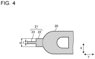
- Fig. 4 is a partially-enlarged cross-sectional view of Fig. 3 .
- a heat exchanger 1 according to Embodiment 1 is described below.
- the heat exchanger 1 includes a plurality of heat transfer parts 2, a first header 3, and a second header 4.
- the plurality of heat transfer parts 2 are spaced from each other in the X-direction, such that air flows in the Y-direction perpendicular to the X-direction between the heat transfer parts 2.
- the plurality of heat transfer parts 2 are each formed into an elongated shape extending in the Z-direction perpendicular to the X-direction and the Y-direction. Opposite ends of the heat transfer parts 2 in the Z-direction are connected to the first header 3 and the second header 4.
- Each of the heat transfer parts 2 includes a heat transfer tube 20 in which refrigerant flows, and fins 21.
- the heat transfer part 2 is of an integrated structure in which the heat transfer tube 20 and the fins 21 are integrated with each other.
- the heat transfer part 2 is made of metal material with heat conductivity. Examples of the metal material to be used include aluminum, aluminum alloy, copper, and copper alloy.
- the heat transfer tube 20 is a flat tube formed into a flat shape in cross-section having the major axis and the minor axis.
- the flat tube has a plurality of refrigerant flow passages 20a made up of through holes.
- the major axis extends in the Y-direction.
- the minor axis extends in the X-direction.
- the heat transfer tube 20 is not limited to the flat tube, but may be a circular tube. Note that the configuration is described in this example in which the plurality of heat transfer parts 2 are provided. However, any number of heat transfer parts 2 may be provided. One or more heat transfer parts 2 are only required.
- Each of the fins 21 is made up of an elongated planar plate that extends along the direction of the tube axis of the heat transfer tube 20.
- the longitudinal direction of the fin 21 corresponds to the Z-direction, while the short-side direction of the fin 21 corresponds to the Y-direction.
- At least two fins 21 are located at positions opposite to each other with the heat transfer tube 20 interposed between the two fins 21.
- the fins 21 are provided at opposite end portions of the heat transfer tube 20 in the Y-direction, and at the middle portion of the heat transfer tube 20 in the X-direction.
- Each of the fins 21 includes an integrated portion 22 at which the fin 21 is integrated with the heat transfer tube 20, and a fin portion 23 that is smaller than the integrated portion 22.
- the fin portion 23 is formed to have a plate thickness "t" that is smaller than a plate thickness "p" of the integrated portion 22. This makes it possible to improve the heat conductivity of the fin 21 compared to the configuration in which the fin 21 is formed in its entirety with a plate thickness equal to that of the integrated portion 22.
- opposite end portions of the fins 21 in the Z-direction are located further inside than opposite end portions of the heat transfer tube 20 in the Z-direction.
- the opposite end portions of the heat transfer tube 20 protrude further outside than the opposite end portions of the fins 21.
- Portions of the heat transfer tube 20 that protrude further outside than the fins 21 are denoted as insertion portions 20b to be inserted into the first header 3 and the second header 4.
- the fin portion 23 is formed to have dimensions such that t/w is equal to 0.1 or smaller, where the plate thickness of the fin portion 23 is represented as "t" and the width of the fin portion 23 is represented as "w.” Because of these dimensions, the weight of the fin 21 can be reduced compared to the case where the fin portion 23 has a plate thickness equal to that of the integrated portion 22. As the plate thickness of the fin portion 23 is reduced, the heat resistance inside the fin material is decreased. Accordingly, heat exchange efficiency between refrigerant and air improves.
- the first header 3 and the second header 4 are hollow containers extending in the X-direction.
- the first header 3 and the second header 4 are each formed into a cuboid shape.
- the shape of the first header 3 and the second header 4 is not particularly limited, but may be a cylindrical or other shape.
- the first header 3 and the second header 4 are formed to have a plurality of insertion holes (not illustrated). In each of the insertion holes of the first header 3, one of the insertion portions 20b of the corresponding one of the heat transfer tubes 20 is inserted. The inserted end portions of the plurality of heat transfer tubes 20 communicate with each other inside the first header 3.
- each of the insertion holes of the second header 4 the other insertion portion 20b of the corresponding one of the heat transfer tubes 20 is inserted.
- the other inserted end portions of the plurality of heat transfer tubes 20 communicate with each other inside the first header 3.
- a refrigerant inlet-outlet pipe 5 is connected to the first header 3.
- a refrigerant inlet-outlet pipe 6 is connected to the second header 4.
- refrigerant flows into the first header 3 from the refrigerant inlet-outlet pipe 5.
- the refrigerant having flowed into the first header 3 is distributed from the first header 3 to the heat transfer tubes 20 of the heat transfer parts 2, and then flows through the heat transfer tubes 20 toward the second header 4.
- the refrigerant flowing through the heat transfer tubes 20 exchanges heat with air flowing in the Y-direction, and subsequently joins together in the second header 4 and flows out of the second header 4 from the refrigerant inlet-outlet pipe 6.
- refrigerant flows into the first header 3 from the refrigerant inlet-outlet pipe 5 connected to the first header 3, and then flows out of the second header 4 from the refrigerant inlet-outlet pipe 6 connected to the second header 4, however, refrigerant may flow in the reverse direction. That is, refrigerant may flow into the second header 4 from the refrigerant inlet-outlet pipe 6 connected to the second header 4, and then flows out of the first header 3 from the refrigerant inlet-outlet pipe 5 connected to the first header 3.
- the fin portion 23 of the fin 21 is formed to have a plate thickness that is smaller than that of the integrated portion 22 as described above. Because of this configuration, the heat conductivity of the fin 21 improves compared to the configuration in which the fin 21 is formed in its entirety with a thickness equal to that of the integrated portion 22. Therefore, heat of the refrigerant is transmitted from the heat transfer tubes 20 efficiently to the fins 21 in their entirety, so that the heat exchange efficiency between the heat transfer parts 2 and air is increased.
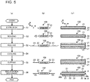
- Figs. 5 are explanatory diagrams illustrating the method of manufacturing the heat transfer part of the heat exchanger according to Embodiment 1.
- Fig. 5(a) is a flowchart of the method of manufacturing the heat transfer part.
- Fig. 5(b) is a cross-sectional view of the heat transfer part in each step taken along the X-Y plane.
- Fig. 5(c) is a side view of the heat transfer part in each step when viewed from the X-direction.
- the method of manufacturing the heat transfer part includes processes in steps S1 to S6.
- Fig. 5(b) illustrates cross-sectional views corresponding to the respective steps.
- Fig. 5(c) illustrates side views corresponding to the respective steps.
- the fin portions are shown by dots.
- Fig. 6 is an end view of the heat transfer tube in cross-section taken along the A-A line in step S6 in Fig. 5(c) .
- extrusion is first performed in which heated metal material is extruded from a die hole to form a heat-transfer-part base 100 having a cross-sectional shape in step S1 in Fig. 5(b) (extrusion process (step S1)).
- the heat-transfer-part base 100 has the heat transfer tube 20 and the two fins 21 formed at opposite end portions of the heat transfer tube 20 in the Y-direction.
- the dimensions of the heat transfer tube 20 are corrected to suit the dimensions of the insertion holes provided in the first header 3 and the second header 4 (resizing process (step S2)).
- This resizing process is performed by applying pressure to the fins 21 from opposite end portions of the heat-transfer-part base 100 in the Y-direction.
- the resizing process is performed before the rolling process is performed next, that is, before the plate thickness of the fins 21 is reduced, so that even when the heat transfer tube 20 is applied with a force, the fins 21 can still be prevented from bending.
- the two fins 21 are extended through application of pressure (rolling process (step S3)).
- the rolling process the fins 21 are extended through application of pressure into a set plate thickness.
- the fin portion 23, that is a portion of the fin 21 other than the integrated portion 22 that is integrated with the heat transfer tube 20, is formed to have a set plate thickness.
- the integrated portion 22 is also extended through application of pressure into a set plate thickness, there may be a possibility that the heat transfer tube 20 can be deformed.
- the fin portion 23 of the fin 21, other than the integrated portion 22, is only extended through application of pressure.
- the rolling process is performed at a temperature exceeding the recrystallization temperature for the material of the heat transfer part 2.
- the heat-transfer-part base 100 having undergone the above processes is cooled (cooling process (step S4)). Subsequently, the end portion of each fin 21 in the Y-direction is cut (cutting process (step S5)). After the rolling process is performed, the end portions of the fins 21 are twisted in Fig. 5(b) . Thus, in the cutting process, the twisted end portions are cut to shape the fins 21. Then, opposite end portions of each fin 21 in the Z-direction are cut (end portion machining process (step S6)). In the end portion machining process, along with the fins 21, opposite end portions of the heat transfer tube 20 in the Y-direction are also cut as illustrated in Fig. 6 .
- the heat transfer tube 20 protrudes further outside than opposite end portions of the fins 21 in the Z-direction, and the insertion portions 20b are thus formed, which are to be inserted into the first header 3 and the second header 4, as illustrated in step S6 in Fig. 5(c) .
- manufacturing of the heat transfer part 2 is completed.
- the method of manufacturing the heat transfer part 2 is not limited to the manufacturing method illustrated in Figs. 5 , but may be modified without departing from the scope of Embodiment 1, for example, in the manner as described below.
- Figs. 7 are explanatory diagrams illustrating a modification of the method of manufacturing the heat transfer part of the heat exchanger according to Embodiment 1. The manufacturing method in Figs. 7 is described below through explanation of the differences from the manufacturing method illustrated in Figs. 5 .
- both two fins 21 are extended through application of pressure simultaneously in the rolling process.
- two fins 21 are extended through application of pressure at different timings. That is, as illustrated in Figs. 7 , one of the two fins 21 is extended through application of pressure (first rolling process (step S3a)), and subsequently the other of the two fins 21 is extended through application of pressure (second rolling process (step S3b)).
- first rolling process step S3a
- second rolling process step S3b
- the heat transfer part 2 is not limited to the configuration of the basic embodiment illustrated in Figs. 1 to 4 , but may be modified without departing from the scope of Embodiment 1, for example, in the manner as described below.
- Figs. 8 illustrate pattern 1 in Modification 1 of the heat transfer part of the heat exchanger according to Embodiment 1.
- Figs. 9 illustrate pattern 2 in Modification 1 of the heat transfer part of the heat exchanger according to Embodiment 1.
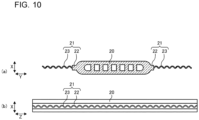
- Figs. 10 illustrate pattern 3 in Modification 1 of the heat transfer part of the heat exchanger according to Embodiment 1.
- Figs. 8(a) , 9(a) , and 10(a) are cross-sectional views of the heat transfer part.
- Figs. 8(b) , 9(b) , and 10(b) are side views of the heat transfer part.
- the fin portions 23 are each formed into a wavy shape.
- the fin portions 23 may have a wavy shape in which wave displacement in the X-direction continues along the Y-direction as illustrated in Figs. 8 .
- the fin portions 23 may have a wavy shape in which wave displacement in the X-direction continues along the Z-direction as illustrated in Figs. 9 .
- the fin portions 23 may have a wavy shape in which wave displacement in the X-direction continues along both the Y-direction and the Z-direction as illustrated in Figs. 10 .
- Such a wavy shape of the fin portions 23 as described above can increase the surface area of the fin portions 23, and consequently improve the heat conductivity to air.
- Such a wavy shape of the fin portions 23 as described above may be formed simultaneously with the rolling process, or may be formed after the rolling process.
- Fig. 11 illustrates Modification 2 of the heat transfer part of the heat exchanger according to Embodiment 1.
- each of the fin portions 23 has an uneven shape 24 on its surface.
- the fin portion 23 has the uneven shape 24 on its surface as described above, so that a flow of air on the surface of the fin portion 23 is turbulent, and the heat conductivity to air can be improved accordingly.
- the uneven shape 24 as described above may be formed simultaneously with the rolling process, or may be formed after the rolling process.
- Fig. 12 illustrates Modification 3 of the heat transfer part of the heat exchanger according to Embodiment 1.
- the integrated portion 22 of the fin 21 that is integrated with the heat transfer tube 20 is positioned at the central portion of the heat transfer tube 20 in the X-direction.
- the integrated portion 22 is positioned at the end portion of the heat transfer tube 20 in the X-direction.
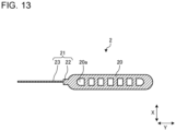
- Fig. 13 illustrates Modification 4 of the heat transfer part of the heat exchanger according to Embodiment 1.
- the fin 21 is provided only at one end of the heat transfer tube 20.
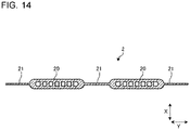
- Fig. 14 illustrates Modification 5 of the heat transfer part of the heat exchanger according to Embodiment 1.
- the heat transfer tube 20 included in the heat transfer part 2 includes a plurality of heat transfer tubes 20.
- the heat transfer tubes 20 are connected to each other by the fin 21.
- Fig. 14 omits illustrations of the integrated portion 22.
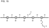
- Fig. 15 illustrates Modification 6 of the heat transfer part of the heat exchanger according to Embodiment 1.
- each of the heat transfer tubes 20 is a circular tube.
- each of the heat transfer tubes 20 of the heat transfer part 2 in the modification in Fig. 14 is made up of a circular tube.
- the heat transfer tube 20 in any of the basic embodiment and Modifications 1 to 5 described above may be a circular tube.
- Fig. 15 omits illustrations of the integrated portion 22.
- Modification 1 and Modification 2 may be combined such that the uneven shape 24 is provided on the surface of the fin portion 23 with a wavy shape.
- the heat exchanger 1 includes the heat transfer part 2 that has the heat transfer tube 20 in which refrigerant flows, and the fin 21 that has an elongated plate shape that extends along a direction of the tube axis of the heat transfer tube 20 and that is integrated with the heat transfer tube 20.
- the fin portion 23 other than the integrated portion 22 that is integrated with the heat transfer tube 20 is formed to have a plate thickness that is smaller than the plate thickness of the integrated portion 22. In this manner, a structure is employed that the heat transfer tube 20 and the fin 21 are integrated with each other and thus the fin 21 and the heat transfer tube 20 do not need to be joined together.
- the fin portion 23 is formed to have a plate thickness that is smaller than the plate thickness of the integrated portion 22. This can improve the heat conductivity of the fin 21 compared to the configuration in which the fin 21 is formed in its entirety with a plate thickness equal to that of the integrated portion 22.
- the fin portion 23 may be formed into a wavy shape, or the uneven shape 24 may be formed on the surface of the fin portion 23.
- the fin portion 23 is formed in this manner, so that the heat conductivity to air can be improved.
- t/w is equal to or smaller than 0.1. Because of these dimensions, the weight of the heat transfer part 2 can be reduced compared to the case where the fin portion 23 has a plate thickness equal to the plate thickness of the integrated portion 22.
- the heat transfer tube 20 included in heat transfer part 2 may include a plurality of heat transfer tubes 20 that are connected to each other by the fin 21.
- Each of the heat transfer tubes 20 may be a flat tube or a circular tube.
- the method of manufacturing the heat exchanger 1 in Embodiment 1 includes an extrusion process for forming the heat transfer tube 20 and the fin 21 through extrusion, and a rolling process for extending the fin 21 through application of pressure.
- the heat transfer tube 20 and the fin 21 are integrated with each other in the manner as described above, so that the need for the joining process can be eliminated, and consequently heat exchange performance can be improved.
- the fin 21 is extended through application of pressure, so that the plate thickness of the fin 21 can be reduced, and the heat conductivity of the heat transfer part 2 can be improved accordingly.
- the fin 21 is extended through application of pressure, except for the integrated portion 22 that is integrated with the heat transfer tube 20. This can reduce deformation of the heat transfer tube 20 during the rolling process.
- the rolling process is performed at a temperature exceeding the recrystallization temperature for the material of the heat transfer part 2.
- the fin 21 can be extended through application of pressure with high machining accuracy.
- a resizing process is performed in between the extrusion process and the rolling process.
- the resizing process corrects the dimensions of the heat transfer tube 20 while the fin 21 is applied with pressure.
- the resizing process is performed before the fin 21 is extended through application of pressure, so that even when the heat transfer tube 20 is applied with a force, the fin 21 can still be prevented from bending.
- the fin 21 includes two fins located at positions opposite to each other with the heat transfer tube 20 interposed between the fins 21.
- the rolling process includes a first process for extending one of the fins 21 through application of pressure, and a second process for extending the other fin 21 through application of pressure, and these first and second processes are performed at different timings. This can reduce deformation of the heat transfer tube 20.
- Embodiment 1 includes a cutting process for cutting the end portion of the fin 21 in the short-side direction after the fin 21 is extended through application of pressure in the rolling process. Because of this cutting process, the twisted portion of the fin 21 after the fin 21 has been extended through application of pressure can be cut to shape the fin 21.
- Embodiment 2 relates to a refrigeration cycle apparatus including the heat exchanger 1 of Embodiment 1 described above.
- Fig. 16 is a refrigerant circuit diagram of the refrigeration cycle apparatus according to Embodiment 2.
- the refrigeration cycle apparatus 200 includes a compressor 201, a condenser 202, a pressure reducing device 203 that is an expansion valve or other valve, and an evaporator 204.
- the heat exchanger 1 of Embodiment 1 is used in one or both of the condenser 202 and the evaporator 204.
- the refrigeration cycle apparatus 200 having the configuration as described above operates in the manner as described below.
- Refrigerant compressed in the compressor 201 flows into the condenser 202.
- the refrigerant having flowed into the condenser 202 exchanges heat with air passing through the condenser 202, is then cooled, and flows into the pressure reducing device 203.
- the refrigerant having flowed into the pressure reducing device 203 is reduced in the pressure, and flows into the evaporator 204.
- the refrigerant having flowed into the evaporator 204 exchanges heat with air passing through the evaporator 204, is thus heated, and then suctioned into the compressor 201 again.
- the refrigeration cycle apparatus 200 of Embodiment 2 includes the heat exchanger 1 of Embodiment 1, the refrigeration cycle apparatus 200 with improved heat exchange performance can be formed.
- refrigeration cycle apparatus 200 is applicable to air-conditioning apparatuses, refrigerators, refrigerating machines, or other machines.
- 1 heat exchanger
- 2 heat transfer part
- 3 first header
- 4 second header
- 5 refrigerant inlet-outlet pipe
- 6 refrigerant inlet-outlet pipe
- 20 heat transfer tube
- 20a refrigerant flow passage
- 20b insertion portion
- 21 fin
- 22 integrated portion
- 23 fin portion
- 24 uneven shape
- 100 heat-transfer-part base
- 200 refrigeration cycle apparatus
- 201 compressor
- 202 condenser
- 203 pressure reducing device
- 204 evaporator
Landscapes
- Engineering & Computer Science (AREA)
- Mechanical Engineering (AREA)
- Physics & Mathematics (AREA)
- Thermal Sciences (AREA)
- General Engineering & Computer Science (AREA)
- Geometry (AREA)
- Heat-Exchange Devices With Radiators And Conduit Assemblies (AREA)
- Extrusion Of Metal (AREA)
Abstract
Description
- The present disclosure relates to a heat exchanger including a heat transfer part that has a heat transfer tube and a fin that extends along a direction of the tube axis of the heat transfer tube, and also relates to a refrigeration cycle apparatus and a method of manufacturing a heat exchanger.
- A heat transfer part for this type of heat exchanger includes a fin that has an elongated plate shape and a recessed portion extending in the longitudinal direction of the fin at the central portion in its short-side direction to braze a heat transfer tube to this recessed portion (see, for example, Patent Literature 1).
- Patent Literature 1:
Japanese Unexamined Patent Application Publication No. 2018-155479 - In
Patent Literature 1, since the fin and the heat transfer tube are formed as separate pieces, both the fin and the heat transfer tube need to be brazed together during the production process. Thus, heat generated because of the brazing causes the fin and the heat transfer tube to be thermally deformed. There is thus a problem in that the occurrence of such thermal deformation results in degradation in the heat exchange performance of the heat exchanger. - From the viewpoint of improvement in heat exchange efficiency, heat exchangers are required to improve heat conductivity of the heat transfer part.
- The present disclosure has been made in view of the above problems, and it is an object of the present disclosure to provide a heat exchanger that improves heat exchange performance by employing a structure that eliminates the need for joining a fin and a heat transfer tube together, and that makes it possible to improve heat conductivity of a heat transfer part, and also to provide a refrigeration cycle apparatus and a method of manufacturing a heat exchanger.
- A heat exchanger according to one embodiment of the present disclosure includes a heat transfer part that has a heat transfer tube that has a refrigerant flow passage inside the heat transfer tube, and a fin that has a plate shape that extends along a direction of a tube axis of the heat transfer tube and that is integrated with the heat transfer tube, the fin having an integrated portion and a fin portion, the integrated portion being a portion at which the fin is integrated with the heat transfer tube, the fin portion being a portion of the fin that is other than the integrated portion, the fin portion having a plate thickness that is smaller than a plate thickness of the integrated portion.
- A refrigeration cycle apparatus according to another embodiment of the present disclosure includes the heat exchanger described above.
- A method of manufacturing a heat exchanger according to still another embodiment of the present disclosure is a method of manufacturing a heat exchanger provided with a heat transfer part that has a heat transfer tube that has a refrigerant flow passage inside the heat transfer tube and a fin that has a plate shape that extends along a direction of a tube axis of the heat transfer tube, the method including an extrusion process for forming the heat transfer tube and the fin through extrusion, and a rolling process for extending the fin through application of pressure. Advantageous Effects of Invention
- According to an embodiment of the present disclosure, a structure is employed in which the heat transfer tube and the fin are integrated with each other. Thus, this makes it possible to avoid thermal deformation during the production process due to heat generated in a case where the heat transfer tube and the fin are joined together, and to consequently improve the heat exchange performance. The fin portion that is a portion of the fin other than the integrated portion that is integrated with the heat transfer tube is formed to have a plate thickness smaller than the plate thickness of the integrated portion. Accordingly, heat conductivity of the heat transfer part can be improved.
-
- [
Fig. 1] Fig. 1 is a perspective view schematically illustrating the configuration of a heat exchanger according toEmbodiment 1. - [
Fig. 2] Fig. 2 is a side view of a heat transfer part of the heat exchanger according toEmbodiment 1. - [
Fig. 3] Fig. 3 is a cross-sectional view of the heat transfer part taken along the A-A line inFig. 2 . - [
Fig. 4] Fig. 4 is a partially-enlarged cross-sectional view ofFig. 3 . - [
Figs. 5] Figs. 5 are explanatory diagrams illustrating a method of manufacturing the heat transfer part of the heat exchanger according toEmbodiment 1. - [
Fig. 6] Fig. 6 is an end view of the heat transfer tube in cross-section taken along the A-A line in step S6 inFig. 5(c) . - [
Figs. 7] Figs. 7 are explanatory diagrams illustrating a modification of the method of manufacturing the heat transfer part of the heat exchanger according toEmbodiment 1. - [
Figs. 8] Figs. 8 illustrate pattern 1 inModification 1 of the heat transfer part of the heat exchanger according toEmbodiment 1. - [
Figs. 9] Figs. 9 illustrate pattern 2 inModification 1 of the heat transfer part of the heat exchanger according toEmbodiment 1. - [
Figs. 10] Figs. 10 illustrate pattern 3 inModification 1 of the heat transfer part of the heat exchanger according toEmbodiment 1. - [
Fig. 11] Fig. 11 illustratesModification 2 of the heat transfer part of the heat exchanger according toEmbodiment 1. - [
Fig. 12] Fig. 12 illustratesModification 3 of the heat transfer part of the heat exchanger according toEmbodiment 1. - [
Fig. 13] Fig. 13 illustratesModification 4 of the heat transfer part of the heat exchanger according toEmbodiment 1. - [
Fig. 14] Fig. 14 illustrates Modification 5 of the heat transfer part of the heat exchanger according toEmbodiment 1. - [
Fig. 15] Fig. 15 illustratesModification 6 of the heat transfer part of the heat exchanger according toEmbodiment 1. - [
Fig. 16] Fig. 16 is a refrigerant circuit diagram of a refrigeration cycle apparatus according toEmbodiment 2. - Embodiments of the present disclosure will be described hereinafter with reference to the drawings. Note that the relative relationship of sizes, the shapes, and other properties of components in the drawings below including
Fig. 1 may differ from those of actual ones. In addition, in the drawings below, the same reference signs denote the same or equivalent components, which are common throughout the entire specification. The shape, size, location, and other properties of the components described in each of the drawings may be appropriately changed within the scope of the present disclosure. -
Fig. 1 is a perspective view schematically illustrating the configuration of a heat exchanger according toEmbodiment 1.Fig. 2 is a side view of a heat transfer part of the heat exchanger according to Embodiment 1.Fig. 3 is a cross-sectional view of the heat transfer part taken along the A-A line inFig. 2 .Fig. 4 is a partially-enlarged cross-sectional view ofFig. 3 . With reference toFigs. 1 to 4 , aheat exchanger 1 according toEmbodiment 1 is described below. - As illustrated in
Fig. 1 , theheat exchanger 1 includes a plurality ofheat transfer parts 2, afirst header 3, and asecond header 4. The plurality ofheat transfer parts 2 are spaced from each other in the X-direction, such that air flows in the Y-direction perpendicular to the X-direction between theheat transfer parts 2. The plurality ofheat transfer parts 2 are each formed into an elongated shape extending in the Z-direction perpendicular to the X-direction and the Y-direction. Opposite ends of theheat transfer parts 2 in the Z-direction are connected to thefirst header 3 and thesecond header 4. - Each of the
heat transfer parts 2 includes aheat transfer tube 20 in which refrigerant flows, andfins 21. Theheat transfer part 2 is of an integrated structure in which theheat transfer tube 20 and thefins 21 are integrated with each other. Theheat transfer part 2 is made of metal material with heat conductivity. Examples of the metal material to be used include aluminum, aluminum alloy, copper, and copper alloy. - As illustrated in
Fig. 3 , theheat transfer tube 20 is a flat tube formed into a flat shape in cross-section having the major axis and the minor axis. The flat tube has a plurality ofrefrigerant flow passages 20a made up of through holes. The major axis extends in the Y-direction. The minor axis extends in the X-direction. Note that theheat transfer tube 20 is not limited to the flat tube, but may be a circular tube. Note that the configuration is described in this example in which the plurality ofheat transfer parts 2 are provided. However, any number ofheat transfer parts 2 may be provided. One or moreheat transfer parts 2 are only required. - Each of the
fins 21 is made up of an elongated planar plate that extends along the direction of the tube axis of theheat transfer tube 20. The longitudinal direction of thefin 21 corresponds to the Z-direction, while the short-side direction of thefin 21 corresponds to the Y-direction. At least twofins 21 are located at positions opposite to each other with theheat transfer tube 20 interposed between the twofins 21. Specifically, thefins 21 are provided at opposite end portions of theheat transfer tube 20 in the Y-direction, and at the middle portion of theheat transfer tube 20 in the X-direction. Each of thefins 21 includes an integratedportion 22 at which thefin 21 is integrated with theheat transfer tube 20, and afin portion 23 that is smaller than the integratedportion 22. As described above, thefin portion 23 is formed to have a plate thickness "t" that is smaller than a plate thickness "p" of the integratedportion 22. This makes it possible to improve the heat conductivity of thefin 21 compared to the configuration in which thefin 21 is formed in its entirety with a plate thickness equal to that of the integratedportion 22. - As illustrated in
Fig. 2 , opposite end portions of thefins 21 in the Z-direction are located further inside than opposite end portions of theheat transfer tube 20 in the Z-direction. The opposite end portions of theheat transfer tube 20 protrude further outside than the opposite end portions of thefins 21. Portions of theheat transfer tube 20 that protrude further outside than thefins 21 are denoted asinsertion portions 20b to be inserted into thefirst header 3 and thesecond header 4. - As illustrated in
Fig. 3 , thefin portion 23 is formed to have dimensions such that t/w is equal to 0.1 or smaller, where the plate thickness of thefin portion 23 is represented as "t" and the width of thefin portion 23 is represented as "w." Because of these dimensions, the weight of thefin 21 can be reduced compared to the case where thefin portion 23 has a plate thickness equal to that of the integratedportion 22. As the plate thickness of thefin portion 23 is reduced, the heat resistance inside the fin material is decreased. Accordingly, heat exchange efficiency between refrigerant and air improves. - The
first header 3 and thesecond header 4 are hollow containers extending in the X-direction. InFig. 1 , thefirst header 3 and thesecond header 4 are each formed into a cuboid shape. However, the shape of thefirst header 3 and thesecond header 4 is not particularly limited, but may be a cylindrical or other shape. Thefirst header 3 and thesecond header 4 are formed to have a plurality of insertion holes (not illustrated). In each of the insertion holes of thefirst header 3, one of theinsertion portions 20b of the corresponding one of theheat transfer tubes 20 is inserted. The inserted end portions of the plurality ofheat transfer tubes 20 communicate with each other inside thefirst header 3. In each of the insertion holes of thesecond header 4, theother insertion portion 20b of the corresponding one of theheat transfer tubes 20 is inserted. The other inserted end portions of the plurality ofheat transfer tubes 20 communicate with each other inside thefirst header 3. A refrigerant inlet-outlet pipe 5 is connected to thefirst header 3. A refrigerant inlet-outlet pipe 6 is connected to thesecond header 4. - In the
heat exchanger 1 having the configuration as described above, refrigerant flows into thefirst header 3 from the refrigerant inlet-outlet pipe 5. The refrigerant having flowed into thefirst header 3 is distributed from thefirst header 3 to theheat transfer tubes 20 of theheat transfer parts 2, and then flows through theheat transfer tubes 20 toward thesecond header 4. The refrigerant flowing through theheat transfer tubes 20 exchanges heat with air flowing in the Y-direction, and subsequently joins together in thesecond header 4 and flows out of thesecond header 4 from the refrigerant inlet-outlet pipe 6. Note that in this example, refrigerant flows into thefirst header 3 from the refrigerant inlet-outlet pipe 5 connected to thefirst header 3, and then flows out of thesecond header 4 from the refrigerant inlet-outlet pipe 6 connected to thesecond header 4, however, refrigerant may flow in the reverse direction. That is, refrigerant may flow into thesecond header 4 from the refrigerant inlet-outlet pipe 6 connected to thesecond header 4, and then flows out of thefirst header 3 from the refrigerant inlet-outlet pipe 5 connected to thefirst header 3. - During heat exchange between air and refrigerant flowing through the
heat transfer tubes 20, heat of the refrigerant flowing through theheat transfer tubes 20 is transferred to thefins 21, so that the heat is exchanged between air and theheat transfer parts 2 in their entirety. Thefin portion 23 of thefin 21 is formed to have a plate thickness that is smaller than that of the integratedportion 22 as described above. Because of this configuration, the heat conductivity of thefin 21 improves compared to the configuration in which thefin 21 is formed in its entirety with a thickness equal to that of the integratedportion 22. Therefore, heat of the refrigerant is transmitted from theheat transfer tubes 20 efficiently to thefins 21 in their entirety, so that the heat exchange efficiency between theheat transfer parts 2 and air is increased. - Next, a method of manufacturing the
heat transfer part 2 is described. -
Figs. 5 are explanatory diagrams illustrating the method of manufacturing the heat transfer part of the heat exchanger according toEmbodiment 1.Fig. 5(a) is a flowchart of the method of manufacturing the heat transfer part.Fig. 5(b) is a cross-sectional view of the heat transfer part in each step taken along the X-Y plane.Fig. 5(c) is a side view of the heat transfer part in each step when viewed from the X-direction. As illustrated inFig. 5(a) , the method of manufacturing the heat transfer part includes processes in steps S1 to S6.Fig. 5(b) illustrates cross-sectional views corresponding to the respective steps.Fig. 5(c) illustrates side views corresponding to the respective steps. InFig. 5(c) , the fin portions are shown by dots.Fig. 6 is an end view of the heat transfer tube in cross-section taken along the A-A line in step S6 inFig. 5(c) . - In manufacturing the
heat transfer part 2, extrusion is first performed in which heated metal material is extruded from a die hole to form a heat-transfer-part base 100 having a cross-sectional shape in step S1 inFig. 5(b) (extrusion process (step S1)). The heat-transfer-part base 100 has theheat transfer tube 20 and the twofins 21 formed at opposite end portions of theheat transfer tube 20 in the Y-direction. Next, the dimensions of theheat transfer tube 20 are corrected to suit the dimensions of the insertion holes provided in thefirst header 3 and the second header 4 (resizing process (step S2)). This resizing process is performed by applying pressure to thefins 21 from opposite end portions of the heat-transfer-part base 100 in the Y-direction. The resizing process is performed before the rolling process is performed next, that is, before the plate thickness of thefins 21 is reduced, so that even when theheat transfer tube 20 is applied with a force, thefins 21 can still be prevented from bending. - Subsequently, the two
fins 21 are extended through application of pressure (rolling process (step S3)). In the rolling process, thefins 21 are extended through application of pressure into a set plate thickness. Through this rolling process, thefin portion 23, that is a portion of thefin 21 other than the integratedportion 22 that is integrated with theheat transfer tube 20, is formed to have a set plate thickness. In this state, if the integratedportion 22 is also extended through application of pressure into a set plate thickness, there may be a possibility that theheat transfer tube 20 can be deformed. In view of the above, thefin portion 23 of thefin 21, other than the integratedportion 22, is only extended through application of pressure. The rolling process is performed at a temperature exceeding the recrystallization temperature for the material of theheat transfer part 2. The reason for this is that when the rolling process is performed at a temperature equal to or below the recrystallization temperature for the material of theheat transfer part 2, the material is hardened, which makes it difficult to form the material into a set plate thickness, and the machining accuracy is thus degraded. - The heat-transfer-
part base 100 having undergone the above processes is cooled (cooling process (step S4)). Subsequently, the end portion of eachfin 21 in the Y-direction is cut (cutting process (step S5)). After the rolling process is performed, the end portions of thefins 21 are twisted inFig. 5(b) . Thus, in the cutting process, the twisted end portions are cut to shape thefins 21. Then, opposite end portions of eachfin 21 in the Z-direction are cut (end portion machining process (step S6)). In the end portion machining process, along with thefins 21, opposite end portions of theheat transfer tube 20 in the Y-direction are also cut as illustrated inFig. 6 . Through this end portion machining process, theheat transfer tube 20 protrudes further outside than opposite end portions of thefins 21 in the Z-direction, and theinsertion portions 20b are thus formed, which are to be inserted into thefirst header 3 and thesecond header 4, as illustrated in step S6 inFig. 5(c) . Through the processes described above, manufacturing of theheat transfer part 2 is completed. - The method of manufacturing the
heat transfer part 2 is not limited to the manufacturing method illustrated inFigs. 5 , but may be modified without departing from the scope ofEmbodiment 1, for example, in the manner as described below. -
Figs. 7 are explanatory diagrams illustrating a modification of the method of manufacturing the heat transfer part of the heat exchanger according toEmbodiment 1. The manufacturing method inFigs. 7 is described below through explanation of the differences from the manufacturing method illustrated inFigs. 5 . - In the manufacturing method illustrated in
Figs. 5 , both twofins 21 are extended through application of pressure simultaneously in the rolling process. In contrast, in this modification, twofins 21 are extended through application of pressure at different timings. That is, as illustrated inFigs. 7 , one of the twofins 21 is extended through application of pressure (first rolling process (step S3a)), and subsequently the other of the twofins 21 is extended through application of pressure (second rolling process (step S3b)). When both twofins 21 positioned opposite to each other with theheat transfer tube 20 interposed between the twofins 21 are extended through application of pressure simultaneously, there may be a possibility that theheat transfer tube 20 may be stretched and deformed. For this reason, in the modification, the twofins 21 are extended through application of pressure one by one at different timings. This can reduce deformation of theheat transfer tube 20. - The
heat transfer part 2 is not limited to the configuration of the basic embodiment illustrated inFigs. 1 to 4 , but may be modified without departing from the scope ofEmbodiment 1, for example, in the manner as described below. -
Figs. 8 illustratepattern 1 inModification 1 of the heat transfer part of the heat exchanger according toEmbodiment 1.Figs. 9 illustratepattern 2 inModification 1 of the heat transfer part of the heat exchanger according toEmbodiment 1.Figs. 10 illustratepattern 3 inModification 1 of the heat transfer part of the heat exchanger according toEmbodiment 1.Figs. 8(a) ,9(a) , and10(a) are cross-sectional views of the heat transfer part.Figs. 8(b) ,9(b) , and10(b) are side views of the heat transfer part. - In
Modification 1, thefin portions 23 are each formed into a wavy shape. Thefin portions 23 may have a wavy shape in which wave displacement in the X-direction continues along the Y-direction as illustrated inFigs. 8 . Thefin portions 23 may have a wavy shape in which wave displacement in the X-direction continues along the Z-direction as illustrated inFigs. 9 . Thefin portions 23 may have a wavy shape in which wave displacement in the X-direction continues along both the Y-direction and the Z-direction as illustrated inFigs. 10 . Such a wavy shape of thefin portions 23 as described above can increase the surface area of thefin portions 23, and consequently improve the heat conductivity to air. Such a wavy shape of thefin portions 23 as described above may be formed simultaneously with the rolling process, or may be formed after the rolling process. -
Fig. 11 illustratesModification 2 of the heat transfer part of the heat exchanger according toEmbodiment 1. - In
Modification 2, each of thefin portions 23 has anuneven shape 24 on its surface. Thefin portion 23 has theuneven shape 24 on its surface as described above, so that a flow of air on the surface of thefin portion 23 is turbulent, and the heat conductivity to air can be improved accordingly. Theuneven shape 24 as described above may be formed simultaneously with the rolling process, or may be formed after the rolling process. -
Fig. 12 illustratesModification 3 of the heat transfer part of the heat exchanger according toEmbodiment 1. - In the above basic embodiment, the integrated
portion 22 of thefin 21 that is integrated with theheat transfer tube 20 is positioned at the central portion of theheat transfer tube 20 in the X-direction. However, inModification 3, the integratedportion 22 is positioned at the end portion of theheat transfer tube 20 in the X-direction. With this configuration, an extension roller used for extending thefins 21 through application of pressure can be simplified. -
Fig. 13 illustratesModification 4 of the heat transfer part of the heat exchanger according toEmbodiment 1. - In
Modification 4, thefin 21 is provided only at one end of theheat transfer tube 20. -
Fig. 14 illustrates Modification 5 of the heat transfer part of the heat exchanger according toEmbodiment 1. - In Modification 5, the
heat transfer tube 20 included in theheat transfer part 2 includes a plurality ofheat transfer tubes 20. Theheat transfer tubes 20 are connected to each other by thefin 21. Note thatFig. 14 omits illustrations of the integratedportion 22. -
Fig. 15 illustratesModification 6 of the heat transfer part of the heat exchanger according toEmbodiment 1. - In
Modification 6, each of theheat transfer tubes 20 is a circular tube. InModification 6, an example is shown in which each of theheat transfer tubes 20 of theheat transfer part 2 in the modification inFig. 14 is made up of a circular tube. However, theheat transfer tube 20 in any of the basic embodiment andModifications 1 to 5 described above may be a circular tube. Note thatFig. 15 omits illustrations of the integratedportion 22. - The above modifications may be appropriately combined. For example,
Modification 1 andModification 2 may be combined such that theuneven shape 24 is provided on the surface of thefin portion 23 with a wavy shape. - As described above, the
heat exchanger 1 according toEmbodiment 1 includes theheat transfer part 2 that has theheat transfer tube 20 in which refrigerant flows, and thefin 21 that has an elongated plate shape that extends along a direction of the tube axis of theheat transfer tube 20 and that is integrated with theheat transfer tube 20. In thefin 21 of theheat transfer part 2, thefin portion 23 other than the integratedportion 22 that is integrated with theheat transfer tube 20 is formed to have a plate thickness that is smaller than the plate thickness of the integratedportion 22. In this manner, a structure is employed that theheat transfer tube 20 and thefin 21 are integrated with each other and thus thefin 21 and theheat transfer tube 20 do not need to be joined together. Therefore, this makes it possible to avoid thefin 21 and theheat transfer tube 20 from being deformed because of heat generated by the joining, and to improve the heat exchange performance. Thefin portion 23 is formed to have a plate thickness that is smaller than the plate thickness of the integratedportion 22. This can improve the heat conductivity of thefin 21 compared to the configuration in which thefin 21 is formed in its entirety with a plate thickness equal to that of the integratedportion 22. - The
fin portion 23 may be formed into a wavy shape, or theuneven shape 24 may be formed on the surface of thefin portion 23. Thefin portion 23 is formed in this manner, so that the heat conductivity to air can be improved. - In the
fin 21, where the plate thickness of thefin portion 23 is represented as "t" and the width of thefin portion 23 in its short-side direction is represented as "w," t/w is equal to or smaller than 0.1. Because of these dimensions, the weight of theheat transfer part 2 can be reduced compared to the case where thefin portion 23 has a plate thickness equal to the plate thickness of the integratedportion 22. - The
heat transfer tube 20 included inheat transfer part 2 may include a plurality ofheat transfer tubes 20 that are connected to each other by thefin 21. Each of theheat transfer tubes 20 may be a flat tube or a circular tube. - The method of manufacturing the
heat exchanger 1 inEmbodiment 1 includes an extrusion process for forming theheat transfer tube 20 and thefin 21 through extrusion, and a rolling process for extending thefin 21 through application of pressure. Theheat transfer tube 20 and thefin 21 are integrated with each other in the manner as described above, so that the need for the joining process can be eliminated, and consequently heat exchange performance can be improved. Thefin 21 is extended through application of pressure, so that the plate thickness of thefin 21 can be reduced, and the heat conductivity of theheat transfer part 2 can be improved accordingly. - In the rolling process, the
fin 21 is extended through application of pressure, except for the integratedportion 22 that is integrated with theheat transfer tube 20. This can reduce deformation of theheat transfer tube 20 during the rolling process. - The rolling process is performed at a temperature exceeding the recrystallization temperature for the material of the
heat transfer part 2. In this temperature state, thefin 21 can be extended through application of pressure with high machining accuracy. - A resizing process is performed in between the extrusion process and the rolling process. The resizing process corrects the dimensions of the
heat transfer tube 20 while thefin 21 is applied with pressure. As described above, the resizing process is performed before thefin 21 is extended through application of pressure, so that even when theheat transfer tube 20 is applied with a force, thefin 21 can still be prevented from bending. - The
fin 21 includes two fins located at positions opposite to each other with theheat transfer tube 20 interposed between thefins 21. The rolling process includes a first process for extending one of thefins 21 through application of pressure, and a second process for extending theother fin 21 through application of pressure, and these first and second processes are performed at different timings. This can reduce deformation of theheat transfer tube 20. -
Embodiment 1 includes a cutting process for cutting the end portion of thefin 21 in the short-side direction after thefin 21 is extended through application of pressure in the rolling process. Because of this cutting process, the twisted portion of thefin 21 after thefin 21 has been extended through application of pressure can be cut to shape thefin 21. -
Embodiment 2 relates to a refrigeration cycle apparatus including theheat exchanger 1 ofEmbodiment 1 described above. -
Fig. 16 is a refrigerant circuit diagram of the refrigeration cycle apparatus according toEmbodiment 2. - The
refrigeration cycle apparatus 200 includes acompressor 201, acondenser 202, apressure reducing device 203 that is an expansion valve or other valve, and anevaporator 204. Theheat exchanger 1 ofEmbodiment 1 is used in one or both of thecondenser 202 and theevaporator 204. - The
refrigeration cycle apparatus 200 having the configuration as described above operates in the manner as described below. - Refrigerant compressed in the
compressor 201 flows into thecondenser 202. The refrigerant having flowed into thecondenser 202 exchanges heat with air passing through thecondenser 202, is then cooled, and flows into thepressure reducing device 203. The refrigerant having flowed into thepressure reducing device 203 is reduced in the pressure, and flows into theevaporator 204. The refrigerant having flowed into theevaporator 204 exchanges heat with air passing through theevaporator 204, is thus heated, and then suctioned into thecompressor 201 again. - Since the
refrigeration cycle apparatus 200 ofEmbodiment 2 includes theheat exchanger 1 ofEmbodiment 1, therefrigeration cycle apparatus 200 with improved heat exchange performance can be formed. - Note that the
refrigeration cycle apparatus 200 is applicable to air-conditioning apparatuses, refrigerators, refrigerating machines, or other machines. - 1: heat exchanger, 2: heat transfer part, 3: first header, 4: second header, 5: refrigerant inlet-outlet pipe, 6: refrigerant inlet-outlet pipe, 20: heat transfer tube, 20a: refrigerant flow passage, 20b: insertion portion, 21: fin, 22: integrated portion, 23: fin portion, 24: uneven shape, 100: heat-transfer-part base, 200: refrigeration cycle apparatus, 201: compressor, 202: condenser, 203: pressure reducing device, 204: evaporator
Claims (13)
- A heat exchanger, comprisinga heat transfer part that hasa heat transfer tube that has a refrigerant flow passage inside the heat transfer tube, anda fin that has a plate shape that extends along a direction of a tube axis of the heat transfer tube and that is integrated with the heat transfer tube,the fin having an integrated portion and a fin portion, the integrated portion being a portion at which the fin is integrated with the heat transfer tube, the fin portion being a portion of the fin that is other than the integrated portion,the fin portion having a plate thickness that is smaller than a plate thickness of the integrated portion.
- The heat exchanger of claim 1, wherein the fin is formed into a wavy shape.
- The heat exchanger of claim 1 or 2, wherein an uneven shape is formed on a surface of the fin.
- The heat exchanger of any one of claims 1 to 3, wherein the heat transfer tube included in the heat transfer part comprises a plurality of heat transfer tubes, the plurality of heat transfer tubes being connected to each other by the fin.
- The heat exchanger of any one of claims 1 to 4, wherein the heat transfer tube is a flat tube.
- The heat exchanger of any one of claims 1 to 4, wherein the heat transfer tube is a circular tube.
- A refrigeration cycle apparatus comprising the heat exchanger of any one of claims 1 to 6.
- A method of manufacturing a heat exchanger provided with a heat transfer part that has a heat transfer tube that has a refrigerant flow passage inside the heat transfer tube and a fin that has a plate shape that extends along a direction of a tube axis of the heat transfer tube, the method comprising:an extrusion process for forming the heat transfer tube and the fin through extrusion; anda rolling process for extending the fin through application of pressure, the rolling process being performed after the extrusion process is performed.
- The method of manufacturing the heat exchanger of claim 8, wherein in the rolling process, the fin is extended through application of pressure, except for an integrated portion of the fin, the integrated portion being integrated with the heat transfer tube.
- The method of manufacturing the heat exchanger of claim 8 or 9, wherein the rolling process is performed at a temperature exceeding a recrystallization temperature for material of the heat transfer part.
- The method of manufacturing the heat exchanger of any one of claims 8 to 10, further comprising a resizing process for correcting a dimension of the heat transfer tube while the fin is applied with pressure, the resizing process being performed in between the extrusion process and the rolling process.
- The method of manufacturing the heat exchanger of any one of claims 8 to 11, wherein the fin comprises two fins located at positions opposite to each other with the heat transfer tube interposed between the two fins, and the rolling process includes a first process for extending one of the two fins through application of pressure, and a second process for extending an other of the two fins through application of pressure, the first and second processes being performed at different timings.
- The method of manufacturing the heat exchanger of any one of claims 8 to 12, further comprising a cutting process for cutting an end portion of the fin in a short-side direction of the fin after the fin is extended through application of pressure in the rolling process.
Applications Claiming Priority (1)
| Application Number | Priority Date | Filing Date | Title |
|---|---|---|---|
| PCT/JP2020/013884 WO2021192189A1 (en) | 2020-03-27 | 2020-03-27 | Heat exchanger, refrigeration cycle device, and method for manufacturing heat exchanger |
Publications (2)
| Publication Number | Publication Date |
|---|---|
| EP4130633A1 true EP4130633A1 (en) | 2023-02-08 |
| EP4130633A4 EP4130633A4 (en) | 2023-04-19 |
Family
ID=77891003
Family Applications (1)
| Application Number | Title | Priority Date | Filing Date |
|---|---|---|---|
| EP20926879.6A Withdrawn EP4130633A4 (en) | 2020-03-27 | 2020-03-27 | Heat exchanger, refrigeration cycle device, and method for manufacturing heat exchanger |
Country Status (3)
| Country | Link |
|---|---|
| EP (1) | EP4130633A4 (en) |
| JP (2) | JPWO2021192189A1 (en) |
| WO (1) | WO2021192189A1 (en) |
Family Cites Families (7)
| Publication number | Priority date | Publication date | Assignee | Title |
|---|---|---|---|---|
| US2347957A (en) * | 1939-06-17 | 1944-05-02 | William E Mccullough | Heat exchange unit |
| JPS411218B1 (en) * | 1963-06-03 | 1966-01-31 | ||
| JPS5214458B2 (en) * | 1973-04-13 | 1977-04-21 | ||
| JPH02117728A (en) * | 1988-10-25 | 1990-05-02 | Sumitomo Metal Ind Ltd | Manufacturing device for outer two-finned tube |
| JPH06117790A (en) * | 1992-10-06 | 1994-04-28 | Sanden Corp | Heat exchanger |
| JP3926934B2 (en) * | 1998-10-15 | 2007-06-06 | 株式会社神戸製鋼所 | Aluminum alloy plate |
| JP2018155479A (en) | 2017-03-16 | 2018-10-04 | ダイキン工業株式会社 | Heat exchanger with heat transfer tube unit |
-
2020
- 2020-03-27 JP JP2022510298A patent/JPWO2021192189A1/ja active Pending
- 2020-03-27 EP EP20926879.6A patent/EP4130633A4/en not_active Withdrawn
- 2020-03-27 WO PCT/JP2020/013884 patent/WO2021192189A1/en not_active Ceased
-
2023
- 2023-09-15 JP JP2023149856A patent/JP2023182618A/en not_active Withdrawn
Also Published As
| Publication number | Publication date |
|---|---|
| JP2023182618A (en) | 2023-12-26 |
| EP4130633A4 (en) | 2023-04-19 |
| JPWO2021192189A1 (en) | 2021-09-30 |
| WO2021192189A1 (en) | 2021-09-30 |
Similar Documents
| Publication | Publication Date | Title |
|---|---|---|
| US9322602B2 (en) | Heat exchanger having a plurality of plate-like fins and a plurality of flat-shaped heat transfer pipes orthogonal to the plate-like fins | |
| EP1452819B1 (en) | Heat exchanger and method for manufacturing the same | |
| EP1438545B1 (en) | Finned tube for heat exchangers, heat exchanger, process for producing heat exchanger finned tube, and process for fabricating heat exchanger | |
| US20030106677A1 (en) | Split fin for a heat exchanger | |
| US10514204B2 (en) | Multiport extruded heat exchanger | |
| US9669455B2 (en) | Method for producing a heat exchanger and heat exchanger obtained by said method, swage and tube expansion device for implementing said method | |
| US20060059946A1 (en) | Finned tube for heat exchangers, heat exchanger, apparatus for fabricating heat exchanger finned tube and process for fabricating heat exchanger finned tube | |
| US20220196345A1 (en) | Heat exchanger, method of manufacturing the same, and air-conditioning apparatus | |
| EP4130633A1 (en) | Heat exchanger, refrigeration cycle device, and method for manufacturing heat exchanger | |
| JP6636110B1 (en) | Air conditioner equipped with heat exchanger, pipe expansion member, and heat exchanger | |
| US12111118B2 (en) | Heat exchanger and heat exchanger manufacturing method | |
| US10220476B2 (en) | Method of manufacturing air conditioning condenser | |
| WO2019058514A1 (en) | Heat exchanger, refrigeration cycle device, and method for manufacturing heat exchanger | |
| EP4137774B1 (en) | Heat exchanger | |
| JP2010276206A (en) | Heat exchanger and article storage device | |
| US20220316812A1 (en) | Heat exchanger, heat exchange unit, refrigeration cycle apparatus, and method for manufacturing heat exchange member | |
| JPWO2003033188A1 (en) | Tubes and heat exchangers with tubes | |
| KR20250136454A (en) | Manufacturing method of integrated pipe for heat exchange and integrated pipe for heat exchange manufactured using the same | |
| CN118912979A (en) | Heat exchanging device | |
| KR20070081346A (en) | Refrigerant tube with inner pin inserted with guide line | |
| JP2007139277A (en) | Heat exchanger | |
| JP2011158123A (en) | Heat exchanger and article storage device |
Legal Events
| Date | Code | Title | Description |
|---|---|---|---|
| STAA | Information on the status of an ep patent application or granted ep patent |
Free format text: STATUS: THE INTERNATIONAL PUBLICATION HAS BEEN MADE |
|
| PUAI | Public reference made under article 153(3) epc to a published international application that has entered the european phase |
Free format text: ORIGINAL CODE: 0009012 |
|
| STAA | Information on the status of an ep patent application or granted ep patent |
Free format text: STATUS: REQUEST FOR EXAMINATION WAS MADE |
|
| 17P | Request for examination filed |
Effective date: 20220823 |
|
| AK | Designated contracting states |
Kind code of ref document: A1 Designated state(s): AL AT BE BG CH CY CZ DE DK EE ES FI FR GB GR HR HU IE IS IT LI LT LU LV MC MK MT NL NO PL PT RO RS SE SI SK SM TR |
|
| A4 | Supplementary search report drawn up and despatched |
Effective date: 20230317 |
|
| RIC1 | Information provided on ipc code assigned before grant |
Ipc: F28F 1/02 20060101ALI20230313BHEP Ipc: F28D 1/053 20060101ALI20230313BHEP Ipc: B21D 53/06 20060101ALI20230313BHEP Ipc: B21C 37/22 20060101ALI20230313BHEP Ipc: B21C 23/10 20060101ALI20230313BHEP Ipc: F28F 1/16 20060101AFI20230313BHEP |
|
| DAV | Request for validation of the european patent (deleted) | ||
| DAX | Request for extension of the european patent (deleted) | ||
| STAA | Information on the status of an ep patent application or granted ep patent |
Free format text: STATUS: EXAMINATION IS IN PROGRESS |
|
| 17Q | First examination report despatched |
Effective date: 20240118 |
|
| GRAP | Despatch of communication of intention to grant a patent |
Free format text: ORIGINAL CODE: EPIDOSNIGR1 |
|
| STAA | Information on the status of an ep patent application or granted ep patent |
Free format text: STATUS: GRANT OF PATENT IS INTENDED |
|
| INTG | Intention to grant announced |
Effective date: 20240930 |
|
| STAA | Information on the status of an ep patent application or granted ep patent |
Free format text: STATUS: THE APPLICATION IS DEEMED TO BE WITHDRAWN |
|
| 18D | Application deemed to be withdrawn |
Effective date: 20250131 |