EP4130624A1 - Container connection module and refrigeration appliance having same - Google Patents
Container connection module and refrigeration appliance having same Download PDFInfo
- Publication number
- EP4130624A1 EP4130624A1 EP21782107.3A EP21782107A EP4130624A1 EP 4130624 A1 EP4130624 A1 EP 4130624A1 EP 21782107 A EP21782107 A EP 21782107A EP 4130624 A1 EP4130624 A1 EP 4130624A1
- Authority
- EP
- European Patent Office
- Prior art keywords
- drinking
- container
- cylindrical portion
- container connecting
- housing
- Prior art date
- Legal status (The legal status is an assumption and is not a legal conclusion. Google has not performed a legal analysis and makes no representation as to the accuracy of the status listed.)
- Granted
Links
Images



Classifications
-
- F—MECHANICAL ENGINEERING; LIGHTING; HEATING; WEAPONS; BLASTING
- F25—REFRIGERATION OR COOLING; COMBINED HEATING AND REFRIGERATION SYSTEMS; HEAT PUMP SYSTEMS; MANUFACTURE OR STORAGE OF ICE; LIQUEFACTION SOLIDIFICATION OF GASES
- F25D—REFRIGERATORS; COLD ROOMS; ICE-BOXES; COOLING OR FREEZING APPARATUS NOT OTHERWISE PROVIDED FOR
- F25D23/00—General constructional features
- F25D23/12—Arrangements of compartments additional to cooling compartments; Combinations of refrigerators with other equipment, e.g. stove
- F25D23/126—Water cooler
-
- B—PERFORMING OPERATIONS; TRANSPORTING
- B67—OPENING, CLOSING OR CLEANING BOTTLES, JARS OR SIMILAR CONTAINERS; LIQUID HANDLING
- B67D—DISPENSING, DELIVERING OR TRANSFERRING LIQUIDS, NOT OTHERWISE PROVIDED FOR
- B67D3/00—Apparatus or devices for controlling flow of liquids under gravity from storage containers for dispensing purposes
- B67D3/0009—Apparatus or devices for controlling flow of liquids under gravity from storage containers for dispensing purposes provided with cooling arrangements
-
- B—PERFORMING OPERATIONS; TRANSPORTING
- B67—OPENING, CLOSING OR CLEANING BOTTLES, JARS OR SIMILAR CONTAINERS; LIQUID HANDLING
- B67D—DISPENSING, DELIVERING OR TRANSFERRING LIQUIDS, NOT OTHERWISE PROVIDED FOR
- B67D3/00—Apparatus or devices for controlling flow of liquids under gravity from storage containers for dispensing purposes
- B67D3/0058—Details
- B67D3/008—Supports
- B67D3/0083—Supports for the liquid container
- B67D3/0087—Supports for the liquid container the beverage container being stored in a rack or shelf
-
- B—PERFORMING OPERATIONS; TRANSPORTING
- B67—OPENING, CLOSING OR CLEANING BOTTLES, JARS OR SIMILAR CONTAINERS; LIQUID HANDLING
- B67D—DISPENSING, DELIVERING OR TRANSFERRING LIQUIDS, NOT OTHERWISE PROVIDED FOR
- B67D3/00—Apparatus or devices for controlling flow of liquids under gravity from storage containers for dispensing purposes
- B67D3/04—Liquid-dispensing taps or cocks adapted to seal and open tapping holes of casks, e.g. for beer
- B67D3/043—Liquid-dispensing taps or cocks adapted to seal and open tapping holes of casks, e.g. for beer with a closing element having a linear movement, in a direction perpendicular to the seat
-
- B—PERFORMING OPERATIONS; TRANSPORTING
- B67—OPENING, CLOSING OR CLEANING BOTTLES, JARS OR SIMILAR CONTAINERS; LIQUID HANDLING
- B67D—DISPENSING, DELIVERING OR TRANSFERRING LIQUIDS, NOT OTHERWISE PROVIDED FOR
- B67D2210/00—Indexing scheme relating to aspects and details of apparatus or devices for dispensing beverages on draught or for controlling flow of liquids under gravity from storage containers for dispensing purposes
- B67D2210/00028—Constructional details
- B67D2210/00031—Housing
- B67D2210/00034—Modules
- B67D2210/00036—Modules for use with or in refrigerators
-
- F—MECHANICAL ENGINEERING; LIGHTING; HEATING; WEAPONS; BLASTING
- F25—REFRIGERATION OR COOLING; COMBINED HEATING AND REFRIGERATION SYSTEMS; HEAT PUMP SYSTEMS; MANUFACTURE OR STORAGE OF ICE; LIQUEFACTION SOLIDIFICATION OF GASES
- F25D—REFRIGERATORS; COLD ROOMS; ICE-BOXES; COOLING OR FREEZING APPARATUS NOT OTHERWISE PROVIDED FOR
- F25D2323/00—General constructional features not provided for in other groups of this subclass
- F25D2323/122—General constructional features not provided for in other groups of this subclass the refrigerator is characterised by a water tank for the water/ice dispenser
Definitions
- the present invention relates to a container connecting module and a refrigerating appliance having the same.
- a refrigerating appliance having a water supply mechanism is described in Japanese Patent 1 Laid-Open Publication No. 2017-36061 .
- a water supply tank for storing drinking water is arranged on the inner side of a heat insulating door that seals a refrigerating chamber formed on the upper layer of a heat insulating cabinet, a water supply chamber with a cavity is formed on the outer side of the heat insulating door, and a water injection rod is disposed inside the water supply chamber.
- a water injection portion communicated with the water supply tank is disposed on the inner side of the upper portion of the water supply chamber.
- cooled drinking water is supplied to a cup from the water supply box through the water injection portion as a user uses the cup to press the water injection rod.
- an object of the present invention is to provide a container connecting module capable of enabling a drinking container to be used as a water supply mechanism in a refrigerating appliance in a simple structure, and a refrigerating appliance having the same.
- a container connecting module is used for being mounted at a drinking opening of a drinking container and includes: a container connecting portion inserted into and connected with the drinking opening of the drinking container; and an outflow regulating portion for stopping and allowing the supply of drinking water from the drinking container, wherein the outer diameter of the container connecting portion is formed as decreasing along a direction towards a drinking container side, and a gap between the container connecting portion and the drinking opening is sealed by contacting the inner wall of the drinking opening of the drinking container with the outer side surface of the container connecting portion.
- the gap between the drinking opening and the container connecting portion can be sealed even if the type of the container connecting portion and the inner diameter of the drinking opening are mismatched to prevent the drinking water from leaking from space between the drinking opening and the container connecting portion.
- the outflow regulating portion includes a cylindrical housing; a first movable cylindrical portion disposed inside the housing, pressed by a pressing member and movably disposed along the axial direction of the housing; a fixed cylindrical portion being integrally formed inside the housing and having one end inserted into the first movable cylindrical portion; and a second movable cylindrical portion disposed inside the fixed cylindrical portion and movably disposed along the axial direction together with the first movable cylindrical portion, wherein when no external force against the pressing member acts on the first movable cylindrical portion, space between the fixed cylindrical portion and the second movable cylindrical portion is sealed by a force applied by the pressing member, such that the supply of the drinking water from the drinking container is stopped; and when an external force against the pressing member acts on the first movable cylindrical portion, a gap is generated between the fixed cylindrical portion and the second movable cylindrical portion, such that the supply of the drinking water from the drinking container is allowed.
- the second movable cylindrical portion moves according to a user
- the outflow regulating portion includes a cover portion surrounding the first movable cylindrical portion. According to the present invention, as the cover portion surrounds the first movable cylindrical portion, the user can be prevented from inadvertently contacting the first movable cylindrical portion and further the drinking water is prevented from flowing out at an inappropriate time.
- the outflow regulating portion further includes a rotary meshing portion rotatably mounted on the housing and meshed with the drinking container.
- the container connecting portion can be firmly mounted at the drinking opening of the drinking container.
- the outflow regulating portion further includes an opening portion formed by forming an opening in a part of the housing; a cylindrical pipe portion being embedded into the housing and having one end connected with the opening portion and the other end led to the outside from the container connecting portion; and a check valve connected with the other end of the pipe portion.
- the check valve communicated with the outside can be disposed in the drinking container, the drinking water can be supplied smoothly from the drinking water.
- a refrigerating appliance includes the container connecting module; a door for sealing a storing chamber; an accommodating region being formed on an inner side surface of the door facing the storing chamber and accommodating the drinking container which makes the container connecting module face downward; a drinking water supply portion formed on an outer side surface facing the outside and equipped with an end of the container connecting module; and a supply rod with one end abutted with the container connecting module and the other end laterally disposed on the drinking water supply portion.
- drinking water can be supplied to a cup via the container connecting module as the user uses a container such as the cup to press the supply rod inward.
- the refrigerating appliance further includes an opening which is formed below the accommodating region and into which the container connecting module is inserted; and a movable cover being rotatably disposed near the accommodating region and plugging the opening. According to the present invention, as the movable cover can plug the opening when the drinking container is not accommodated in the accommodating region, cold air in a refrigerating chamber can be prevented from escaping to the outside via the opening.
- a container connecting module 40 and a refrigerating appliance 10 are described in detail below with reference to the accompanying drawings.
- the same symbol is given to the same member for omitting repeated description.
- directions, i.e., upper, lower, front, rear, left and right are used appropriately, wherein left and right means left and right in the case where a refrigerating appliance 10 is viewed from the front.
- the refrigerating appliance 10 has a freezing chamber and a refrigerating chamber, but the refrigerating appliance 10 may only have the freezing chamber or the refrigerating chamber.
- FIG. 1 is a front view showing an appearance of a refrigerating appliance 10 according to an embodiment of the present invention.
- the refrigerating appliance 10 has a heat insulating cabinet 11 as a main body, into which a storing chamber for storing foods and the like is formed.
- the storing chamber includes a refrigerating chamber 15, an upper freezing chamber 18, a lower freezing chamber 19 and a vegetable chamber 20 from top to bottom in sequence.
- both the upper freezing chamber 18 and the lower freezing chamber 19 are storing chambers within a freezing temperature range, and collectively called as a freezing chamber 17 sometimes in the following description.
- the upper freezing chamber 18 is separable in a horizontal direction, and one side of the upper freezing chamber 18 is used as an ice making chamber.
- Openings are formed in the front of the heat insulating cabinet 11, and heat insulating doors 21, which are freely opened and closed, are disposed at the openings corresponding to the above respective storing chambers, respectively.
- the heat insulating door 21 is separable in a horizontal direction and seals a front surface of the refrigerating chamber 15. Therefore, the upper end and the lower end of the outer side of the heat insulating door 21 in the width direction are freely and rotatably mounted on the heat insulating cabinet 11.
- the heat insulating door 23, the heat insulating door 24 and the heat insulating door 25 are integrally assembled with respective accommodating containers, respectively, and are supported by the heat insulating cabinet 11 so as to be freely pulled out toward the front of the refrigerating appliance 10.
- the heat insulating door 23 seals the upper freezing chamber 18, the heat insulating door 24 seals the lower freezing chamber 19, and the heat insulating door 25 seals the vegetable chamber 20.
- a drinking water supply portion 54 is formed on the heat insulating door 21 sealing a left portion of the freezing chamber 15. As described below, the drinking water supply portion 54 is a concave portion for supplying drinking water cooled inside the refrigerating chamber 15 to a cup 61.
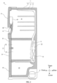
- FIG. 2 is lateral sectional view showing an internal structure of the refrigerating appliance 10.
- the heat insulating cabinet 11 as the main body of the refrigerating appliance 10 consists of an shell 12 which has a front opening and is made of a steel plate; and an inner 13 which is disposed inside the shell 12, has a front opening and is made of synthetic resin. There is a gap between the inner 13 and the shell 12. The gap between the shell 12 and the inner 13 is filled with a heat insulating material 14 made of polyurethane for foaming.
- the above respective heat insulating doors 21 also adopt the same heat insulating structure as the heat insulating cabinet 11.
- the refrigerating chamber 15 is separated from the freezing chamber 17 located below the refrigerating chamber 15 by a heat-insulating partition wall. Moreover, the freezing chamber 17 is separated from the vegetable chamber 20 by a heat-insulating partition wall.
- a refrigerating chamber air supply path as an air supply path for supplying cold air to the refrigerating chamber 15 is formed on the back of the refrigerating chamber 15.
- a freezing chamber air supply path for allowing cold air cooled by a cooler 22 to flow toward the freezing chamber 17 is formed on the rear side of the freezing chamber 17.
- a cooling chamber 26 is formed on a further rear side of the freezing chamber air supply path, and the cooler 22 is disposed inside the cooling chamber 26, and is an evaporator for cooling air circulating in the refrigerating appliance.
- Air inside the cooling chamber 26 cooled by the cooler 22 is blown to the refrigerating chamber 15, the freezing chamber 17 and the vegetable chamber 20 through an air supply fan 16.
- the cooler 22 is connected with a refrigerant pipe through a compressor 27, a heat radiator not shown in the figures, and a capillary tube not shown in the figures and used as an expansion means, to form a vapor compression type freezing circulating loop.
- a drinking container 42 is disposed on the inner side of the heat insulating door 21, and drinking water inside the drinking container 42 is also cooled inside the refrigerating chamber 15.
- the drinking water supplied from the drinking container 42 is supplied to the cup 61 disposed by the user at a drinking water supply portion 54.
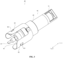
- FIG. 3 is a stereoscopic diagram showing the container connecting module 40.
- the container connecting module 40 mainly includes a container connecting portion 44 and an outflow regulating portion 45.
- the container connecting module 40 is mounted at a drinking opening 43 of the drinking container 42 described later, prevents the drinking water from flowing out of the drinking container 42 when no user's operation exists, and supplies the drinking water to the cup 61 and the like from the drinking container 42 when the user's operation exists.
- the container connecting portion 44 takes a shape with the outer diameter decreasing upwards.
- a gap between the container connecting portion 44 and the drinking opening 43 is sealed by contacting an outer side surface of the container connecting portion 44 with an inner wall of the drinking opening 43 of the drinking container 42 described later.
- a check valve 57 is led out to the outside from an upper end opening of the container connecting portion 44.
- the outflow regulating portion 45 has the functions of preventing the drinking water from being supplied from the drinking container 42 when no user's operation exists and supplying the drinking water from the drinking container 42 when the user's operation exists. A specific structure of the outflow regulating portion 45 will be described in detail below with reference to FIG. 4 .
- Rotary meshing portions 52 are rotatably mounted at positions near an upper end of the housing 46 and meshed with the drinking container 42 described later.
- two rotary meshing portions 52 are mounted on opposite portions of the outflow regulating portion 45, respectively.
- a substantially rectangular meshing opening 521 is formed in an upper portion of the rotary meshing portion 52. As described below, the meshing opening 521 is meshed with a flange portion 421 of the drinking container 42.
- the housing 46 constitutes a design portion of the container connecting module 40 and has a substantially cylindrical shape with an upper portion thicker than a lower portion thereof.
- a cover portion 51 surrounding a first movable cylindrical portion 48 is disposed at a lower end portion of the housing 46.
- FIG. 4(A) is an exploded view showing the container connecting module 40
- FIG. 4(B) is a lateral sectional view showing the container connecting module 40.
- meshing protrusions 58 substantially protruding cylindrically toward the outside along the radial direction are formed at positions opposite to the outer peripheral surface of the housing 46, respectively.
- the meshing protrusions 58 of the housing 46 are rotatably embedded into engaging openings 59 formed in lower portions of the rotary meshing portions 52, respectively.
- the rotary meshing portions 52 are rotatably disposed outside the housing 46.
- the container connecting module 40 has the housing 46, the first movable cylindrical portion 48, a fixed cylindrical portion 49 and a second movable cylindrical portion 50 radially.
- the first movable cylindrical portion 48 is disposed below the inner side of the housing 46, is pressed by a pressing member 47, and moves along the axial direction according to the user's operation.
- the lower end portion of the first movable cylindrical portion 48 has a substantially conical shape with the diameter decreasing downward.
- the lower end portion of the first movable cylindrical portion 48 is meshed with the lower end portion of the second movable cylindrical portion 50.
- the fixed cylindrical portion 49 is a substantially cylindrical member disposed inside the housing 46.
- the upper end portion of the fixed cylindrical portion 49 is connected with the housing 46 and is tapering in diameter.
- the fixed cylindrical portion 49 is fixed inside the container connecting module 40.
- the second movable cylindrical portion 50 is a substantially cylindrical member embedded in the fixed cylindrical portion 49 with the outer diameter gradually decreasing downward, and is substantially cylindrical. As described above, the lower end portion of the second movable cylindrical portion 50 is meshed with the lower end portion of the first movable cylindrical portion 48. Therefore, after being subjected to a force applied by the pressing member 47, the second movable cylindrical portion 50 moves vertically together with the first movable cylindrical portion 48.
- a sealing member 62 is meshed with the outer surface of the lower end portion of the second movable cylindrical portion 50.
- the sealing member 62 is an O-ring made of, for example, rubber or flexible resin. Through the force applied by the pressing member 47, the sealing member 62 is compressed and thus deformed between the inner surface of the fixed cylindrical portion 49 and the outer surface of the second movable cylindrical portion 50, so that space between the inner surface of the fixed cylindrical portion 49 and the outer surface of the second movable cylindrical portion 50 is sealed. Thus, as described later, the supply of the drinking water from the drinking container 42 is stopped when no user's operation exists.
- the second movable cylindrical portion 50 also moves upward inside the fixed cylindrical portion 49 at the same time and thus the sealing member 62 leaves the inner surface of the fixed cylindrical portion 49.
- the drinking water is supplied to the outside from the drinking container 42 through the space between the inner surface of the fixed cylindrical potion 49 and the outer surface of the second movable cylindrical portion 50.
- the pressing member 47 such as a spiral spring, is disposed between the housing 46 and the first movable cylindrical portion 48.
- the upper end portion of the pressing member 47 is abutted against a wall-shaped portion formed inside the housing 46, and the lower end portion of the pressing member 47 is abutted against a step portion formed inside the first movable cylindrical portion 48.
- the pressing member 47 presses the first movable cylindrical portion 48 downward.
- the sealing member 62 mounted outside the second movable cylindrical portion 50 meshed with the first movable cylindrical portion 48 is pressed toward the inner surface of the fixed cylindrical portion 49.
- the cover portion 51 is disposed at the lower end portion of the housing 46 and surrounds and protects the first movable cylindrical portion 48.
- the container connecting portion 44 is a substantially cylindrical member mounted at the upper end of the housing 46 and is formed of a material that is easily elastically deformed, such as rubber and flexible resin.
- the container connecting portion 44 has a substantially cylindrical shape as a whole, and an external upper end portion thereof takes a shape with the outer diameter decreasing upward. That is, an inclined surface 441 is formed outside the upper end of the container connecting portion 44.
- the outer diameter L11 at the lower end of the inclined surface is set to be greater than or equal to the maximum outer diameter of the drinking opening 43 of the drinking container 42 described later.
- the outer diameter L10 at the upper end of the inclined surface is set to be less than or equal to the minimum outer diameter of the drinking opening 43 of the drinking container 42 described later.
- the drinking container 42 described with reference to FIG. 5 is of such two types that the inner diameter of the drinking opening 43 thereof is 20 mm and the inner diameter of the drinking opening 43 thereof is 21 mm. Therefore, in this embodiment, as an example, L11 as the maximum outer diameter of the inclined surface 441 is set to 21 mm or above, and L10 as the minimum outer diameter of the inclined surface 441 is set to be less than 20 mm.
- the container connecting portion 44 of the container connecting module 40 may be inserted without a gap into the drinking opening 43 of the drinking container 42 with different opening diameters so as to prevent the drinking water from flowing out to the outside from space between the drinking opening 43 of the container connecting module 40 and the container connecting portion 44 of the container connecting module 40.
- a pipe portion 56 is embedded into the upper portion of the housing 46.
- a lower end portion of the pipe portion 56 is communicated with an opening portion 55 ( FIG. 4 (A) ) formed in the housing 46, and the upper end portion of the housing 46 is led out to the outside from the opening of the container connecting portion 44.
- the upper end of the pipe portion 56 is connected with the check valve 57.
- the check valve 57 allows air introduced from the pipe portion 56 to circulate toward a drinking container 42 side, and prevents the drinking water from circulating toward a pipe portion 56 side.
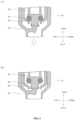
- FIG. 5 is a diagram showing the container connecting module 40, wherein FIG. 5(A) is a sectional view showing an intermediate stage in which the drinking container 42 is connected with the container connecting module 40, and FIG. 5(B) is a sectional view showing a state in which the container connecting module 40 is connected with the drinking container 42.
- the drinking opening 43 and the flange portions 421 are formed at the end of the drinking container 42.
- the container connecting module 40 is mounted on the drinking container 42, first the rotary meshing portions 52 of the container connecting module 40 are opened by rotating outward along a radial direction.
- the container connecting portion 44 of the container connecting module 40 is inserted into the drinking opening 43 of the drinking container 42.
- the minimum outer diameter of the inclined surface 441 of the container connecting portion 44 is set to be smaller than the inner diameter of the drinking opening 43.
- the maximum outer diameter of the inclined surface 441 is set to be greater than the inner diameter of the drinking opening 43. Therefore, when the container connecting portion 44 formed of a flexible material is inserted into the drinking opening 43, the outer surface of the container connecting portion 44 is in close fit with the inner surface of the drinking opening 43. Thus, the drinking water inside the drinking container 42 does not leak from a place where the drinking opening 43 is in contact with the container connecting portion 44.
- the rotary meshing portions 52 are closed inwards in the radial direction.
- the flange portions 421 of the drinking container 42 are meshed with the meshing openings 521 of the rotary meshing portions 52, and the container connecting module 40 is not disengaged from the drinking container 42.
- FIG. 6 is a stereoscopic diagram showing a state in which the drinking container 42 connected with the container connecting module 40 is mounted into the heat insulating door 21 of the refrigerating appliance 10
- FIG. 6(A) is a stereoscopic diagram showing an intermediate stage of mounting
- FIG. 6(B) is a stereoscopic diagram showing a state after mounting.
- an accommodating region 53 is formed by recessing an inner surface of the heat insulating door 21 forwards.
- a baffle portion 60 is disposed in the accommodating region 53.
- the baffle portion 60 is a substantially plate-shaped member and is mounted on the inner surface of the heat insulating door 21 in a state that the left end and the right end thereof can slide vertically.
- the accommodating region 53 has, for example, a volume capable of accommodating two drinking containers 42, such as two 2-liter PET bottles.
- the drinking container 42 is accommodated in the accommodating region 53 in a state that the container connecting module 40 is mounted at the lower end thereof.
- the baffle portion 60 slides towards the lower side of the accommodating region 53.
- the operation of storing the drinking container 42 in the accommodating region 53 is not hindered by the baffle portion 60.
- the drinking container 42 when the drinking container 42 is placed by lowering the baffle portion 60, the accommodating operation of the heat insulating door 24 becomes easier.
- the baffle portion 60 by raising the baffle portion 60, the drinking container 42 can be stabilized when the heat insulating door 21 is opened and closed.
- FIG. 6 (B) by raising the baffle portion 60, lock catches are meshed to work, and the drinking container 42 is slightly pressed forward.
- the baffle portion 60 is lowered or raised, the baffle portion 60 is operated slightly away from the drinking container 42.
- the baffle portion 60 moves upward.
- the lower portion of the drinking container 42 is supported by the baffle portion 60, and hence can be stably accommodated in the accommodating region 53.
- FIG. 7 is a stereoscopic diagram showing a state in which the drinking container 42 connected with the container connecting module 40 is mounted into the heat insulating door 21 of the refrigerating appliance 10, wherein FIG. 7(A) is a sectional view of the heat insulating door 21, and FIG. 7(B) is a stereoscopic diagram of the heat insulating door 21 as viewed from the outside.
- the drinking water supply portion 54 is a cavity formed by recessing rearward the lower portion of the front of the heat insulating door 21.
- the drinking water supply portion 54 has, for example, a volume capable of accommodating two cups 61 into which the drinking water is supplied from the drinking container 42.
- FIG. 8 is a diagram showing an associating structure between the container connecting module 40 and the supply rod 41, wherein FIG. 8(A) is a stereoscopic diagram showing the container connecting module 40 and the supply rod 41, and FIG. 8(B) is a stereoscopic diagram showing the supply rod 41.
- the supply rod 41 is disposed at the lower end of the container connecting module 40.
- the upper end of the supply rod 41 is in contact with the lower end of the container connecting module 40.
- the lower end of the first movable cylindrical portion 48 is pressed against protrusion portions 414 of the supply rod 41 described later by the force applied by the pressing member 47 shown in FIG. 4(B) .
- the supply rod 41 is a substantially hook-shaped member, and has an abutting portion 411 vertically extending and being abutted against the cup 61, contact portions 413 extending horizontally and being in contact with the container connecting module 40, a corner portion 412 as a connecting portion between the contact portions 413 and the abutting portion 411, and meshing holes 415 acquired by forming openings in front ends of the contact portions 413.
- the protrusion portion 414 is formed by partially bulging the rear end of the upper side of the contact portion 413 upward.
- the supply rod 41 is rotatably connected with the body side of the refrigerating appliance 10 through the meshing holes 415.
- FIG. 9 is a diagram showing the container connecting module 40
- FIG. 9(A) is a sectional view showing the container connecting module 40 in a closed state in which drinking water is prevented from flowing out
- FIG. 9(B) is a sectional view showing the container connecting module 40 in an open state in which the drinking water is allowed to flow out.
- FIG. 10 With reference to FIG. 10 , the structure in which the drinking container 42 is mounted in the accommodating region 53 of the heat insulating door 21 is further described.
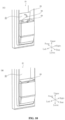
- a movable cover 64 that appropriately plugs openings 63 is disposed in the accommodating region 53.
- FIG. 10(A) shows the movable cover in an open state
- FIG. 10(B) shows the movable cover in a closed state.
- the openings 63 for insertion of the drinking openings 43 of the drinking containers 42 and the container connecting module 40 are formed in the bottom surface of the accommodating region 53.
- two drinking containers 42 are accommodated in the accommodating region 53, and thus two openings 63 are formed.
- the openings 63 connect the refrigerating chamber 15 with the outside. Therefore, in the case where no drinking container 42 is disposed in the accommodating region 53, when the openings 63 are kept as they are, cold air in the refrigerating chamber 15 escapes outward through the openings 63, and there is a risk of reducing the cooling efficiency of the refrigerating chamber 15. Therefore, in this embodiment, the movable cover 64 is disposed in the accommodating region 53.
- the movable cover 64 is a plate-shaped member having a substantially rectangular shape, and two ends of a lower side edge are rotatably mounted on the front end side of the bottommost portion of the accommodating region 53.
- the movable cover 64 is accommodated on the inner side surface of the accommodating region 53 in an upright state.
- the movable cover 64 is switched to the horizontal state by rotating the movable cover 64, and the openings 63 can be plugged by the movable cover 64. In this way, the cold air can be prevented from leaking to the outside through the openings 63. Further, stored items, such as food, can be carried and accommodated on the movable cover 64.
- the gap between the container connecting portion 44 and the drinking opening 43 can be sealed even if the type of the container connecting portion and the inner diameter of the drinking opening are mismatched to prevent the drinking water from leaking from space between the container connecting portion 44 and the drinking opening 43.
- the second movable cylindrical portion 50 moves according to the user's operation.
- the supply of the drinking water can be stopped when no user's operation exists, and the drinking water can be supplied when the user's operation exists.
- the user can be prevented from inadvertently contacting the first movable cylindrical portion 48, and further the drinking water is prevented from flowing out unnecessarily.
- the container connecting portion 44 can be firmly mounted at the drinking opening 43 of the drinking container 42.
- the check valve 57 communicated with the outside can be disposed in the drinking container 42, and thus, the drinking water can be supplied smoothly from the drinking water 42.
- the drinking water stored in the drinking container 42 can be cooled through the refrigerating chamber 15, and the cooled drinking water can be provided to the user through a simple structure.
- the present invention is not limited to the above embodiments, and various other changes may be implemented without departing from the main purpose of the present invention.
- the above embodiments may be combined with one another.
Landscapes
- Engineering & Computer Science (AREA)
- Mechanical Engineering (AREA)
- Chemical & Material Sciences (AREA)
- Combustion & Propulsion (AREA)
- Physics & Mathematics (AREA)
- Thermal Sciences (AREA)
- General Engineering & Computer Science (AREA)
- Devices For Dispensing Beverages (AREA)
Abstract
Description
- The present invention relates to a container connecting module and a refrigerating appliance having the same.
- Traditionally, it is known that a refrigerating appliance having a water supply mechanism is described in
Japanese Patent 1 Laid-Open Publication No. 2017-36061 - In the water supply chamber of the refrigerating appliance adopting the above structure, cooled drinking water is supplied to a cup from the water supply box through the water injection portion as a user uses the cup to press the water injection rod.
- However, in the refrigerating appliance with the above water supply mechanism, it is necessary to dispose the water supply tank dedicated to water supply on the inner side of the heat insulating door. In addition, if drinking water inside the water supply tank is insufficient, it needs to supply water to the water supply tank by the user. As a result, there is a problem of inconvenient use of the water supply mechanism. In addition, in the case where tap water is supplied to the water supply tank, there is another problem that the safety of the tap water and the like may not be guaranteed depending on the countries and regions using the refrigerating appliance.
- In view of the above circumstances, an object of the present invention is to provide a container connecting module capable of enabling a drinking container to be used as a water supply mechanism in a refrigerating appliance in a simple structure, and a refrigerating appliance having the same.
- A container connecting module is used for being mounted at a drinking opening of a drinking container and includes: a container connecting portion inserted into and connected with the drinking opening of the drinking container; and an outflow regulating portion for stopping and allowing the supply of drinking water from the drinking container, wherein the outer diameter of the container connecting portion is formed as decreasing along a direction towards a drinking container side, and a gap between the container connecting portion and the drinking opening is sealed by contacting the inner wall of the drinking opening of the drinking container with the outer side surface of the container connecting portion. According to the present invention, by contacting the inner wall of the drinking opening of the drinking container with the outer side surface of the container connecting portion, the gap between the drinking opening and the container connecting portion can be sealed even if the type of the container connecting portion and the inner diameter of the drinking opening are mismatched to prevent the drinking water from leaking from space between the drinking opening and the container connecting portion.
- In a further embodiment of the present invention, the outflow regulating portion includes a cylindrical housing; a first movable cylindrical portion disposed inside the housing, pressed by a pressing member and movably disposed along the axial direction of the housing; a fixed cylindrical portion being integrally formed inside the housing and having one end inserted into the first movable cylindrical portion; and a second movable cylindrical portion disposed inside the fixed cylindrical portion and movably disposed along the axial direction together with the first movable cylindrical portion, wherein when no external force against the pressing member acts on the first movable cylindrical portion, space between the fixed cylindrical portion and the second movable cylindrical portion is sealed by a force applied by the pressing member, such that the supply of the drinking water from the drinking container is stopped; and when an external force against the pressing member acts on the first movable cylindrical portion, a gap is generated between the fixed cylindrical portion and the second movable cylindrical portion, such that the supply of the drinking water from the drinking container is allowed. According to the present invention, the second movable cylindrical portion moves according to a user's operation. Thus, the drinking water can be prevented from flowing out when no user's operation exists, and can be supplied when the user's operation exists.
- In a further embodiment of the present invention, the outflow regulating portion includes a cover portion surrounding the first movable cylindrical portion. According to the present invention, as the cover portion surrounds the first movable cylindrical portion, the user can be prevented from inadvertently contacting the first movable cylindrical portion and further the drinking water is prevented from flowing out at an inappropriate time.
- In a further embodiment of the present invention, the outflow regulating portion further includes a rotary meshing portion rotatably mounted on the housing and meshed with the drinking container. According to the present invention, as the rotary meshing portion is meshed with the drinking container, the container connecting portion can be firmly mounted at the drinking opening of the drinking container.
- In a further embodiment of the present invention, the outflow regulating portion further includes an opening portion formed by forming an opening in a part of the housing; a cylindrical pipe portion being embedded into the housing and having one end connected with the opening portion and the other end led to the outside from the container connecting portion; and a check valve connected with the other end of the pipe portion. According to the present invention, as the check valve communicated with the outside can be disposed in the drinking container, the drinking water can be supplied smoothly from the drinking water.
- A refrigerating appliance includes the container connecting module; a door for sealing a storing chamber; an accommodating region being formed on an inner side surface of the door facing the storing chamber and accommodating the drinking container which makes the container connecting module face downward; a drinking water supply portion formed on an outer side surface facing the outside and equipped with an end of the container connecting module; and a supply rod with one end abutted with the container connecting module and the other end laterally disposed on the drinking water supply portion. According to the present invention, drinking water can be supplied to a cup via the container connecting module as the user uses a container such as the cup to press the supply rod inward.
- In a further embodiment of the present invention, the refrigerating appliance further includes an opening which is formed below the accommodating region and into which the container connecting module is inserted; and a movable cover being rotatably disposed near the accommodating region and plugging the opening. According to the present invention, as the movable cover can plug the opening when the drinking container is not accommodated in the accommodating region, cold air in a refrigerating chamber can be prevented from escaping to the outside via the opening.
-
-
FIG. 1 is a front view showing an appearance of a refrigerating appliance according to an embodiment of the present invention; -
FIG. 2 is a lateral sectional view showing an internal structure of the refrigerating appliance according to the embodiment of the present invention; -
FIG. 3 is a stereoscopic diagram showing a container connecting module according to an embodiment of the present invention; -
FIG. 4 is a diagram showing the container connecting module according to the embodiment of the present invention, wherein (A) is an exploded view and (B) is a sectional view; -
FIG. 5 is a diagram showing the container connecting module according to the embodiment of the present invention, wherein (A) is a sectional view showing an intermediate stage in which a drinking container and the container connecting module are connected, and (B) is a sectional view showing a state in which the container connecting module and the drinking container are connected; -
FIG. 6 is a stereoscopic diagram showing a state in which the drinking container connected with the container connecting module according to the embodiment of the present invention is mounted into a heat insulating door of a refrigerating appliance, wherein (A) is a stereoscopic diagram showing an intermediate stage of mounting, and (B) is a stereoscopic diagram showing a state after mounting; -
FIG. 7 is a diagram showing a state in which the drinking container connected with the container connecting module according to the embodiment of the present invention is mounted into a heat insulating door of a refrigerating appliance, wherein (A) is a stereoscopic diagram showing an intermediate state of mounting, and (B) is a stereoscopic diagram showing a state after mounting; -
FIG. 8 is a diagram showing an associating structure between the container connecting module according to the embodiment of the present invention and a supply rod, wherein (A) is a stereoscopic diagram showing the container connecting module and the supply rod, and (B) is a stereoscopic diagram showing the supply rod; -
FIG. 9 is a diagram showing the container connecting module according to the embodiment of the present invention, wherein (A) is a sectional view showing the container connecting module in a closed state in which drinking water is prevented from flowing out, and (B) is a sectional view showing the container connecting module in an open state in which the drinking water is allowed to flow out; and -
FIG. 10 is a diagram showing a structure in which the drinking container connected with the container connecting module according to the embodiment of the present invention is mounted into the heat insulating door, wherein (A) shows a movable cover in an open state, and (B) shows the movable cover in a closed state. - Reference signs in the
figures: 10 -refrigerating appliance, 11-heat insulating cabinet, 12-shell, 13-inner; 14-heat insulating material, 15-refrigerating chamber, 16-air supply fan, 17-freezing chamber, 18-upper freezing chamber, 19-lower freezing chamber, 20-vegetable chamber, 21-heat insulating door, 22-cooler, 23-heat insulating door, 24-heat insulating door, 25-heat insulating door, 26-cooling chamber, 27-compressor, 40-container connecting module, 41-supply rod, 411-abutting portion, 412-corner portion, 413-contact portion, 414-protrusion portion, 415-meshing hole, 42-drinking container, 421-flange portion, 43-drinking opening, 44-container connecting portion, 441-inclined surface, 45-outflow regulating portion, 46-housing, 47-pressing member, 48-first movable cylindrical portion, 49-fixed cylindrical portion, 50-second movable cylindrical portion, 51-cover portion, 52-rotary meshing portion, 521-meshing opening, 53-accommodating region, 54-drinking water supply portion, 5-opening portion, 56-pipe portion, 57-check valve, 58-meshing protrusion, 59-engaging opening, 60-baffle portion, 61-cup, 62-sealing member, 63-opening, and 64-movable cover. - A
container connecting module 40 and a refrigeratingappliance 10 according to embodiments of the present invention are described in detail below with reference to the accompanying drawings. In the following description, in principle, the same symbol is given to the same member for omitting repeated description. In addition, directions, i.e., upper, lower, front, rear, left and right, are used appropriately, wherein left and right means left and right in the case where a refrigeratingappliance 10 is viewed from the front. In addition, in embodiments, as an example, the refrigeratingappliance 10 has a freezing chamber and a refrigerating chamber, but the refrigeratingappliance 10 may only have the freezing chamber or the refrigerating chamber. -
FIG. 1 is a front view showing an appearance of a refrigeratingappliance 10 according to an embodiment of the present invention. The refrigeratingappliance 10 has aheat insulating cabinet 11 as a main body, into which a storing chamber for storing foods and the like is formed. The storing chamber includes a refrigeratingchamber 15, anupper freezing chamber 18, alower freezing chamber 19 and avegetable chamber 20 from top to bottom in sequence. In addition, both theupper freezing chamber 18 and thelower freezing chamber 19 are storing chambers within a freezing temperature range, and collectively called as afreezing chamber 17 sometimes in the following description. Here, theupper freezing chamber 18 is separable in a horizontal direction, and one side of theupper freezing chamber 18 is used as an ice making chamber. - Openings are formed in the front of the
heat insulating cabinet 11, andheat insulating doors 21, which are freely opened and closed, are disposed at the openings corresponding to the above respective storing chambers, respectively. Theheat insulating door 21 is separable in a horizontal direction and seals a front surface of the refrigeratingchamber 15. Therefore, the upper end and the lower end of the outer side of theheat insulating door 21 in the width direction are freely and rotatably mounted on theheat insulating cabinet 11. In addition, theheat insulating door 23, theheat insulating door 24 and theheat insulating door 25 are integrally assembled with respective accommodating containers, respectively, and are supported by theheat insulating cabinet 11 so as to be freely pulled out toward the front of the refrigeratingappliance 10. Specifically, theheat insulating door 23 seals theupper freezing chamber 18, theheat insulating door 24 seals thelower freezing chamber 19, and theheat insulating door 25 seals thevegetable chamber 20. - In this embodiment, a drinking
water supply portion 54 is formed on theheat insulating door 21 sealing a left portion of thefreezing chamber 15. As described below, the drinkingwater supply portion 54 is a concave portion for supplying drinking water cooled inside the refrigeratingchamber 15 to acup 61. -
FIG. 2 is lateral sectional view showing an internal structure of the refrigeratingappliance 10. Theheat insulating cabinet 11 as the main body of the refrigeratingappliance 10 consists of anshell 12 which has a front opening and is made of a steel plate; and an inner 13 which is disposed inside theshell 12, has a front opening and is made of synthetic resin. There is a gap between the inner 13 and theshell 12. The gap between theshell 12 and the inner 13 is filled with aheat insulating material 14 made of polyurethane for foaming. In addition, the above respectiveheat insulating doors 21 also adopt the same heat insulating structure as theheat insulating cabinet 11. - The refrigerating
chamber 15 is separated from thefreezing chamber 17 located below the refrigeratingchamber 15 by a heat-insulating partition wall. Moreover, thefreezing chamber 17 is separated from thevegetable chamber 20 by a heat-insulating partition wall. - A refrigerating chamber air supply path as an air supply path for supplying cold air to the refrigerating
chamber 15 is formed on the back of the refrigeratingchamber 15. - A freezing chamber air supply path for allowing cold air cooled by a cooler 22 to flow toward the freezing
chamber 17 is formed on the rear side of the freezingchamber 17. A cooling chamber 26 is formed on a further rear side of the freezing chamber air supply path, and the cooler 22 is disposed inside the cooling chamber 26, and is an evaporator for cooling air circulating in the refrigerating appliance. - Air inside the cooling chamber 26 cooled by the cooler 22 is blown to the refrigerating
chamber 15, the freezingchamber 17 and thevegetable chamber 20 through anair supply fan 16. - The cooler 22 is connected with a refrigerant pipe through a
compressor 27, a heat radiator not shown in the figures, and a capillary tube not shown in the figures and used as an expansion means, to form a vapor compression type freezing circulating loop. - A
drinking container 42 is disposed on the inner side of theheat insulating door 21, and drinking water inside thedrinking container 42 is also cooled inside the refrigeratingchamber 15. In addition, the drinking water supplied from thedrinking container 42 is supplied to thecup 61 disposed by the user at a drinkingwater supply portion 54. -
FIG. 3 is a stereoscopic diagram showing thecontainer connecting module 40. Thecontainer connecting module 40 mainly includes acontainer connecting portion 44 and anoutflow regulating portion 45. Thecontainer connecting module 40 is mounted at adrinking opening 43 of thedrinking container 42 described later, prevents the drinking water from flowing out of thedrinking container 42 when no user's operation exists, and supplies the drinking water to thecup 61 and the like from thedrinking container 42 when the user's operation exists. - The
container connecting portion 44 takes a shape with the outer diameter decreasing upwards. A gap between thecontainer connecting portion 44 and thedrinking opening 43 is sealed by contacting an outer side surface of thecontainer connecting portion 44 with an inner wall of the drinking opening 43 of thedrinking container 42 described later. Acheck valve 57 is led out to the outside from an upper end opening of thecontainer connecting portion 44. - The
outflow regulating portion 45 has the functions of preventing the drinking water from being supplied from thedrinking container 42 when no user's operation exists and supplying the drinking water from thedrinking container 42 when the user's operation exists. A specific structure of theoutflow regulating portion 45 will be described in detail below with reference toFIG. 4 . -
Rotary meshing portions 52 are rotatably mounted at positions near an upper end of thehousing 46 and meshed with thedrinking container 42 described later. Here, tworotary meshing portions 52 are mounted on opposite portions of theoutflow regulating portion 45, respectively. In addition, a substantiallyrectangular meshing opening 521 is formed in an upper portion of therotary meshing portion 52. As described below, themeshing opening 521 is meshed with aflange portion 421 of thedrinking container 42. - The
housing 46 constitutes a design portion of thecontainer connecting module 40 and has a substantially cylindrical shape with an upper portion thicker than a lower portion thereof. In addition, acover portion 51 surrounding a first movablecylindrical portion 48 is disposed at a lower end portion of thehousing 46. - The structure of the
container connecting module 40 is described in detail with reference toFIG. 4. FIG. 4(A) is an exploded view showing thecontainer connecting module 40, andFIG. 4(B) is a lateral sectional view showing thecontainer connecting module 40. - With reference to
FIG. 4(A) , meshing protrusions 58 substantially protruding cylindrically toward the outside along the radial direction are formed at positions opposite to the outer peripheral surface of thehousing 46, respectively. The meshing protrusions 58 of thehousing 46 are rotatably embedded into engagingopenings 59 formed in lower portions of therotary meshing portions 52, respectively. Thus, therotary meshing portions 52 are rotatably disposed outside thehousing 46. - As shown in
FIG. 4(B) , thecontainer connecting module 40 has thehousing 46, the first movablecylindrical portion 48, a fixedcylindrical portion 49 and a second movablecylindrical portion 50 radially. - The first movable
cylindrical portion 48 is disposed below the inner side of thehousing 46, is pressed by a pressing member 47, and moves along the axial direction according to the user's operation. The lower end portion of the first movablecylindrical portion 48 has a substantially conical shape with the diameter decreasing downward. In addition, the lower end portion of the first movablecylindrical portion 48 is meshed with the lower end portion of the second movablecylindrical portion 50. - The fixed
cylindrical portion 49 is a substantially cylindrical member disposed inside thehousing 46. The upper end portion of the fixedcylindrical portion 49 is connected with thehousing 46 and is tapering in diameter. The fixedcylindrical portion 49 is fixed inside thecontainer connecting module 40. - The second movable
cylindrical portion 50 is a substantially cylindrical member embedded in the fixedcylindrical portion 49 with the outer diameter gradually decreasing downward, and is substantially cylindrical. As described above, the lower end portion of the second movablecylindrical portion 50 is meshed with the lower end portion of the first movablecylindrical portion 48. Therefore, after being subjected to a force applied by the pressing member 47, the second movablecylindrical portion 50 moves vertically together with the first movablecylindrical portion 48. - A sealing
member 62 is meshed with the outer surface of the lower end portion of the second movablecylindrical portion 50. The sealingmember 62 is an O-ring made of, for example, rubber or flexible resin. Through the force applied by the pressing member 47, the sealingmember 62 is compressed and thus deformed between the inner surface of the fixedcylindrical portion 49 and the outer surface of the second movablecylindrical portion 50, so that space between the inner surface of the fixedcylindrical portion 49 and the outer surface of the second movablecylindrical portion 50 is sealed. Thus, as described later, the supply of the drinking water from thedrinking container 42 is stopped when no user's operation exists. In addition, as described later, through the user's operation, if the first movablecylindrical portion 48 moves upward, the second movablecylindrical portion 50 also moves upward inside the fixedcylindrical portion 49 at the same time and thus the sealingmember 62 leaves the inner surface of the fixedcylindrical portion 49. Hence, the drinking water is supplied to the outside from thedrinking container 42 through the space between the inner surface of the fixedcylindrical potion 49 and the outer surface of the second movablecylindrical portion 50. - The pressing member 47, such as a spiral spring, is disposed between the
housing 46 and the first movablecylindrical portion 48. The upper end portion of the pressing member 47 is abutted against a wall-shaped portion formed inside thehousing 46, and the lower end portion of the pressing member 47 is abutted against a step portion formed inside the first movablecylindrical portion 48. The pressing member 47 presses the first movablecylindrical portion 48 downward. Thus, the sealingmember 62 mounted outside the second movablecylindrical portion 50 meshed with the first movablecylindrical portion 48 is pressed toward the inner surface of the fixedcylindrical portion 49. - The
cover portion 51 is disposed at the lower end portion of thehousing 46 and surrounds and protects the first movablecylindrical portion 48. - As described above, the
container connecting portion 44 is a substantially cylindrical member mounted at the upper end of thehousing 46 and is formed of a material that is easily elastically deformed, such as rubber and flexible resin. Thecontainer connecting portion 44 has a substantially cylindrical shape as a whole, and an external upper end portion thereof takes a shape with the outer diameter decreasing upward. That is, aninclined surface 441 is formed outside the upper end of thecontainer connecting portion 44. The outer diameter L11 at the lower end of the inclined surface is set to be greater than or equal to the maximum outer diameter of the drinking opening 43 of thedrinking container 42 described later. The outer diameter L10 at the upper end of the inclined surface is set to be less than or equal to the minimum outer diameter of the drinking opening 43 of thedrinking container 42 described later. Thus, even if the inner diameter of the drinking opening 43 of thedrinking container 42 described later is uneven, the outside of theinclined surface 441 of thecontainer connecting portion 44 can be reliably embedded inside the drinking opening 43 of thedrinking container 42. - In Japan, the
drinking container 42 described with reference toFIG. 5 is of such two types that the inner diameter of the drinking opening 43 thereof is 20 mm and the inner diameter of the drinking opening 43 thereof is 21 mm. Therefore, in this embodiment, as an example, L11 as the maximum outer diameter of theinclined surface 441 is set to 21 mm or above, and L10 as the minimum outer diameter of theinclined surface 441 is set to be less than 20 mm. By setting the outer diameter of theinclined surface 441 in such a range, thecontainer connecting portion 44 of thecontainer connecting module 40 may be inserted without a gap into the drinking opening 43 of thedrinking container 42 with different opening diameters so as to prevent the drinking water from flowing out to the outside from space between the drinking opening 43 of thecontainer connecting module 40 and thecontainer connecting portion 44 of thecontainer connecting module 40. - A
pipe portion 56 is embedded into the upper portion of thehousing 46. A lower end portion of thepipe portion 56 is communicated with an opening portion 55 (FIG. 4 (A) ) formed in thehousing 46, and the upper end portion of thehousing 46 is led out to the outside from the opening of thecontainer connecting portion 44. In addition, the upper end of thepipe portion 56 is connected with thecheck valve 57. Thecheck valve 57 allows air introduced from thepipe portion 56 to circulate toward adrinking container 42 side, and prevents the drinking water from circulating toward apipe portion 56 side. -
FIG. 5 is a diagram showing thecontainer connecting module 40, whereinFIG. 5(A) is a sectional view showing an intermediate stage in which thedrinking container 42 is connected with thecontainer connecting module 40, andFIG. 5(B) is a sectional view showing a state in which thecontainer connecting module 40 is connected with thedrinking container 42. - With reference to
FIG. 5(A) , thedrinking opening 43 and theflange portions 421 are formed at the end of thedrinking container 42. When thecontainer connecting module 40 is mounted on thedrinking container 42, first therotary meshing portions 52 of thecontainer connecting module 40 are opened by rotating outward along a radial direction. - In this state, the
container connecting portion 44 of thecontainer connecting module 40 is inserted into the drinking opening 43 of thedrinking container 42. As described above, the minimum outer diameter of theinclined surface 441 of thecontainer connecting portion 44 is set to be smaller than the inner diameter of thedrinking opening 43. In addition, the maximum outer diameter of theinclined surface 441 is set to be greater than the inner diameter of thedrinking opening 43. Therefore, when thecontainer connecting portion 44 formed of a flexible material is inserted into thedrinking opening 43, the outer surface of thecontainer connecting portion 44 is in close fit with the inner surface of thedrinking opening 43. Thus, the drinking water inside thedrinking container 42 does not leak from a place where thedrinking opening 43 is in contact with thecontainer connecting portion 44. - With reference to
FIG. 5(B) , therotary meshing portions 52 are closed inwards in the radial direction. Thus, theflange portions 421 of thedrinking container 42 are meshed with the meshingopenings 521 of therotary meshing portions 52, and thecontainer connecting module 40 is not disengaged from thedrinking container 42. -
FIG. 6 is a stereoscopic diagram showing a state in which thedrinking container 42 connected with thecontainer connecting module 40 is mounted into theheat insulating door 21 of the refrigeratingappliance 10,FIG. 6(A) is a stereoscopic diagram showing an intermediate stage of mounting, andFIG. 6(B) is a stereoscopic diagram showing a state after mounting. - With reference to
FIG. 6(A) , anaccommodating region 53 is formed by recessing an inner surface of theheat insulating door 21 forwards. Abaffle portion 60 is disposed in theaccommodating region 53. Thebaffle portion 60 is a substantially plate-shaped member and is mounted on the inner surface of theheat insulating door 21 in a state that the left end and the right end thereof can slide vertically. Theaccommodating region 53 has, for example, a volume capable of accommodating twodrinking containers 42, such as two 2-liter PET bottles. Thedrinking container 42 is accommodated in theaccommodating region 53 in a state that thecontainer connecting module 40 is mounted at the lower end thereof. When thedrinking container 42 is stored in theaccommodating region 53, thebaffle portion 60 slides towards the lower side of theaccommodating region 53. Thus, the operation of storing thedrinking container 42 in theaccommodating region 53 is not hindered by thebaffle portion 60. - Here, when the
drinking container 42 is placed by lowering thebaffle portion 60, the accommodating operation of theheat insulating door 24 becomes easier. In addition, by raising thebaffle portion 60, thedrinking container 42 can be stabilized when theheat insulating door 21 is opened and closed. As shown inFIG. 6 (B) , by raising thebaffle portion 60, lock catches are meshed to work, and thedrinking container 42 is slightly pressed forward. In addition, when thebaffle portion 60 is lowered or raised, thebaffle portion 60 is operated slightly away from thedrinking container 42. - With reference to
FIG. 6 (B) , thebaffle portion 60 moves upward. Thus, the lower portion of thedrinking container 42 is supported by thebaffle portion 60, and hence can be stably accommodated in theaccommodating region 53. -
FIG. 7 is a stereoscopic diagram showing a state in which thedrinking container 42 connected with thecontainer connecting module 40 is mounted into theheat insulating door 21 of the refrigeratingappliance 10, whereinFIG. 7(A) is a sectional view of theheat insulating door 21, andFIG. 7(B) is a stereoscopic diagram of theheat insulating door 21 as viewed from the outside. - With reference to
FIG. 7 (A) , when thedrinking container 42 is inversely accommodated in theaccommodating region 53, the lower end of thecontainer connecting portion 44 mounted on thedrinking container 42 is exposed to the inner side of the upper end of the drinkingwater supply portion 54. In addition, a hook-shaped supply rod 41 is rotatably disposed on the inner side of the drinkingwater supply portion 54. - With reference to
FIG. 7 (B) , the drinkingwater supply portion 54 is a cavity formed by recessing rearward the lower portion of the front of theheat insulating door 21. The drinkingwater supply portion 54 has, for example, a volume capable of accommodating twocups 61 into which the drinking water is supplied from thedrinking container 42. -
FIG. 8 is a diagram showing an associating structure between thecontainer connecting module 40 and the supply rod 41, whereinFIG. 8(A) is a stereoscopic diagram showing thecontainer connecting module 40 and the supply rod 41, andFIG. 8(B) is a stereoscopic diagram showing the supply rod 41. - With reference to
FIG. 8(A) , the supply rod 41 is disposed at the lower end of thecontainer connecting module 40. The upper end of the supply rod 41 is in contact with the lower end of thecontainer connecting module 40. In detail, the lower end of the first movablecylindrical portion 48 is pressed againstprotrusion portions 414 of the supply rod 41 described later by the force applied by the pressing member 47 shown inFIG. 4(B) . - With reference to
FIG. 8(B) , the supply rod 41 is a substantially hook-shaped member, and has an abutting portion 411 vertically extending and being abutted against thecup 61,contact portions 413 extending horizontally and being in contact with thecontainer connecting module 40, acorner portion 412 as a connecting portion between thecontact portions 413 and the abutting portion 411, and meshingholes 415 acquired by forming openings in front ends of thecontact portions 413. In addition, theprotrusion portion 414 is formed by partially bulging the rear end of the upper side of thecontact portion 413 upward. The supply rod 41 is rotatably connected with the body side of the refrigeratingappliance 10 through the meshing holes 415. - By adopting such a structure, when the user presses the front of the abutting portion 411 of the supply rod 41 backward with the rear end of the
cup 61 not shown, the supply rod 41 rotates with the meshing holes 415 as a pivot point, and theprotrusion portions 414 are pushed up. Thus, as described later, upper end portions of thecontact portions 413 push up the first movablecylindrical portion 48 and the second movablecylindrical portion 50 of thecontainer connecting module 40, and hence, the drinking water can be supplied from thedrinking container 42 to thecup 61. -
FIG. 9 is a diagram showing thecontainer connecting module 40,FIG. 9(A) is a sectional view showing thecontainer connecting module 40 in a closed state in which drinking water is prevented from flowing out; andFIG. 9(B) is a sectional view showing thecontainer connecting module 40 in an open state in which the drinking water is allowed to flow out. - With reference to
FIG. 9 (A) , in thecontainer connection module 40 in the closed state, the first movablecylindrical portion 48 and the fixedcylindrical portion 49 are not pushed up from below. Therefore, the space between the outer surface of the second movablecylindrical portion 50 and the inner surface of the fixedcylindrical portion 49 is sealed by the sealingmember 62. Thus, the drinking water stored in theabove drinking container 42 does not flow out of thecontainer connecting module 40. - With reference to
FIG. 9(B) , in thecontainer connecting module 40 in the open state, the lower end of the first movablecylindrical portion 48 is pushed up by theprotrusion portions 414 of the supply rod 41 shown inFIG. 8(B) . Thus, the second movablecylindrical portion 50 is also pushed up inside the fixedcylindrical portion 49. Therefore, a sealingmaterial 62 embedded in the top end of the second movablecylindrical portion 50 leaves the inner surface of the fixedcylindrical portion 49. Hence, the drinking water stored in thedrinking container 42 flows through the space between the second movablecylindrical portion 50 and the fixedcylindrical portion 49 and is supplied to thecup 61 via thecontainer connecting module 40. Afterwards, if the user removes thecup 61 from the abutting portion 411 shown inFIG. 8(B) after thecup 61 is filled with the drinking water, thecontainer connecting module 40 returns to the closed state shown inFIG. 9(A) and stops the supply of the drinking water. - With reference to
FIG. 10 , the structure in which thedrinking container 42 is mounted in theaccommodating region 53 of theheat insulating door 21 is further described. Here, a movable cover 64 that appropriately plugs openings 63 is disposed in theaccommodating region 53.FIG. 10(A) shows the movable cover in an open state, andFIG. 10(B) shows the movable cover in a closed state. - With reference to
FIG. 10(A) , the openings 63 for insertion of thedrinking openings 43 of thedrinking containers 42 and thecontainer connecting module 40 are formed in the bottom surface of theaccommodating region 53. Here, twodrinking containers 42 are accommodated in theaccommodating region 53, and thus two openings 63 are formed. The openings 63 connect the refrigeratingchamber 15 with the outside. Therefore, in the case where no drinkingcontainer 42 is disposed in theaccommodating region 53, when the openings 63 are kept as they are, cold air in the refrigeratingchamber 15 escapes outward through the openings 63, and there is a risk of reducing the cooling efficiency of the refrigeratingchamber 15. Therefore, in this embodiment, the movable cover 64 is disposed in theaccommodating region 53. - The movable cover 64 is a plate-shaped member having a substantially rectangular shape, and two ends of a lower side edge are rotatably mounted on the front end side of the bottommost portion of the
accommodating region 53. Here, the movable cover 64 is accommodated on the inner side surface of theaccommodating region 53 in an upright state. - With reference to
FIG. 10(B) , in the case where no drinkingcontainer 42 is accommodated in theaccommodating region 53, the movable cover 64 is switched to the horizontal state by rotating the movable cover 64, and the openings 63 can be plugged by the movable cover 64. In this way, the cold air can be prevented from leaking to the outside through the openings 63. Further, stored items, such as food, can be carried and accommodated on the movable cover 64. - The following describes main effects achieved through this embodiment.
- According to the present invention, as shown in
FIG. 4(B) , by contacting the inner wall of the drinking opening 43 of thedrinking container 42 with the outer side surface of thecontainer connecting portion 44, the gap between thecontainer connecting portion 44 and thedrinking opening 43 can be sealed even if the type of the container connecting portion and the inner diameter of the drinking opening are mismatched to prevent the drinking water from leaking from space between thecontainer connecting portion 44 and thedrinking opening 43. - In addition, as shown in
FIG. 9 , the second movablecylindrical portion 50 moves according to the user's operation. Thus, the supply of the drinking water can be stopped when no user's operation exists, and the drinking water can be supplied when the user's operation exists. - In addition, as shown in
FIG. 4 , as thecover portion 51 surrounds the first movablecylindrical portion 48, the user can be prevented from inadvertently contacting the first movablecylindrical portion 48, and further the drinking water is prevented from flowing out unnecessarily. - In addition, as shown in
FIG. 4(B) , as therotary meshing portion 52 is meshed with thedrinking container 42, thecontainer connecting portion 44 can be firmly mounted at the drinking opening 43 of thedrinking container 42. - In addition, as shown in
FIG. 5 , thecheck valve 57 communicated with the outside can be disposed in thedrinking container 42, and thus, the drinking water can be supplied smoothly from thedrinking water 42. - In addition, as shown in
FIG. 2 , the drinking water stored in thedrinking container 42 can be cooled through the refrigeratingchamber 15, and the cooled drinking water can be provided to the user through a simple structure. - The present invention is not limited to the above embodiments, and various other changes may be implemented without departing from the main purpose of the present invention. In addition, the above embodiments may be combined with one another.
Claims (11)
- A container connecting module (40) for being mounted at a drinking opening (43) of a drinking container (42), the container connecting module (40) comprising:a container connecting portion (44) inserted into and connected with the drinking opening (43) of the drinking container (42); andan outflow regulating portion (45) for stopping and allowing the supply of drinking water from the drinking container (42), whereinan outer diameter of the container connecting portion (44) is formed as decreasing along a direction towards a drinking container (42) side, anda gap between the container connecting portion (44) and the drinking opening (43) is sealed by contacting an inner wall of the drinking opening (43) of the drinking container (42) with an outer side surface of the container connecting portion (44).
- The container connecting module (40) according to claim 1, wherein the outflow regulating portion (45) comprises:a cylindrical housing (46);a first movable cylindrical portion (48) disposed inside the housing (46), pressed by a pressing member (47) and movably disposed along an axial direction of the housing (46);a fixed cylindrical portion (49) being integrally formed inside the housing (46) and having one end inserted into the first movable cylindrical portion (48); anda second movable cylindrical portion (50) disposed inside the fixed cylindrical portion (49) and movably disposed along the axial direction together with the first movable cylindrical portion (48), whereinwhen no external force against the pressing member (47) acts on the first movable cylindrical portion (48), space between the fixed cylindrical portion (49) and the second movable cylindrical portion (50) is sealed by a force applied by the pressing member (47), such that the supply of the drinking water from the drinking container (42) is stopped; andwhen an external force against the pressing member (47) acts on the first movable cylindrical portion (48), a gap is generated between the fixed cylindrical portion (49) and the second movable cylindrical portion (50), such that the supply of the drinking water from the drinking container (42) is allowed.
- The container connecting module (40) according to claim 2, wherein the outflow regulating portion (45) comprises a cover portion (51) surrounding the first movable cylindrical portion (48).
- The container connecting module (40) according to claim 2, wherein the outflow regulating portion (45) further comprises a rotary meshing portion (52) rotatably mounted on the housing (46) and meshed with the drinking container (42).
- The container connecting module (40) according to claim 2, wherein the outflow regulating portion (45) further comprises:an opening portion (55) formed by forming an opening (63) in a part of the housing (46);a cylindrical pipe portion (56) being embedded into the housing (46) and having one end connected with the opening portion (55) and the other end led to the outside from the container connecting portion (44); anda check valve (57) connected with the other end of the pipe portion (56).
- A refrigerating appliance (10), comprising the container connecting module (40) according to claim 1, and further comprising:a door (21,23,24,25) for sealing a storing chamber;an accommodating region (53) being formed on an inner side surface of the door (21,23,24,25) facing the storing chamber and accommodating the drinking container (42) which makes the container connecting module (40) face downward;a drinking water supply portion (54) formed on an outer side surface facing the outside and equipped with an end of the container connecting module (40); anda supply rod (41) with one end abutted with the container connecting module (40) and the other end laterally disposed on the drinking water supply portion (54).
- The refrigerating appliance (10) according to claim 6, further comprising:an opening (63) which is formed below the accommodating region (53) and into which the container connecting module (40) is inserted; anda movable cover (64) being rotatably disposed near the accommodating region (53) and plugging the opening (63).
- The refrigerating appliance (10) according to claim 6, wherein the outflow regulating portion (45) comprises:a cylindrical housing (46);a first movable cylindrical portion (48) disposed inside the housing (46), pressed by a pressing member (47) and movably disposed along an axial direction of the housing (46);a fixed cylindrical portion (49) being integrally formed inside the housing (46) and having one end inserted into the first movable cylindrical portion (48); anda second movable cylindrical portion (50) disposed inside the fixed cylindrical portion (49) and movably disposed along the axial direction together with the first movable cylindrical portion (48), whereinwhen no external force against the pressing member (47) acts on the first movable cylindrical portion (48), space between the fixed cylindrical portion (49) and the second movable cylindrical portion (50) is sealed by a force applied by the pressing member (47), such that the supply of the drinking water from the drinking container (42) is stopped; andwhen an external force against the pressing member (47) acts on the first movable cylindrical portion (48), a gap is generated between the fixed cylindrical portion (49) and the second movable cylindrical portion (50), such that the supply of the drinking water from the drinking container (42) is allowed.
- The refrigerating appliance (10) according to claim 8, wherein the outflow regulating portion (45) comprises a cover portion (51) surrounding the first movable cylindrical portion (48).
- The refrigerating appliance (10) according to claim 8, wherein the outflow regulating portion (45) further comprises a rotary meshing portion (52) rotatably mounted on the housing (46) and meshed with the drinking container (42).
- The refrigerating appliance (10) according to claim 8, wherein the outflow regulating portion (45) further comprises:an opening portion (55) formed by forming an opening (63) in a part of the housing (46);a cylindrical pipe portion (56) being embedded into the housing (46) and having one end connected with the opening portion (55) and the other end led to the outside from the container connecting portion (44); anda check valve (57) connected with the other end of the pipe portion (56).
Applications Claiming Priority (2)
| Application Number | Priority Date | Filing Date | Title |
|---|---|---|---|
| JP2020066637A JP7455370B2 (en) | 2020-04-02 | 2020-04-02 | Container connection module and refrigerator with it |
| PCT/CN2021/078839 WO2021196959A1 (en) | 2020-04-02 | 2021-03-03 | Container connection module and refrigeration appliance having same |
Publications (3)
| Publication Number | Publication Date |
|---|---|
| EP4130624A1 true EP4130624A1 (en) | 2023-02-08 |
| EP4130624A4 EP4130624A4 (en) | 2023-08-30 |
| EP4130624B1 EP4130624B1 (en) | 2025-04-23 |
Family
ID=77927232
Family Applications (1)
| Application Number | Title | Priority Date | Filing Date |
|---|---|---|---|
| EP21782107.3A Active EP4130624B1 (en) | 2020-04-02 | 2021-03-03 | Container connecting module and refrigerating appliance having same |
Country Status (4)
| Country | Link |
|---|---|
| EP (1) | EP4130624B1 (en) |
| JP (2) | JP7455370B2 (en) |
| CN (1) | CN115335653B (en) |
| WO (1) | WO2021196959A1 (en) |
Families Citing this family (2)
| Publication number | Priority date | Publication date | Assignee | Title |
|---|---|---|---|---|
| JP2023095128A (en) * | 2021-12-24 | 2023-07-06 | アクア株式会社 | refrigerator |
| JP7530681B2 (en) * | 2022-08-10 | 2024-08-08 | アクア株式会社 | CONTAINER CONNECTION MODULE, DISPENSER UNIT AND REFRIGERATOR |
Family Cites Families (25)
| Publication number | Priority date | Publication date | Assignee | Title |
|---|---|---|---|---|
| US1918767A (en) * | 1932-03-24 | 1933-07-18 | Rhinelander Refrigerator Co | Water cooler |
| US2512395A (en) * | 1946-01-19 | 1950-06-20 | Seeger Refrigerator Co | Liquid dispensing apparatus |
| GB627115A (en) * | 1947-04-21 | 1949-07-28 | Gaskell & Chambers Ltd | Improvements relating to measuring taps |
| GB862166A (en) * | 1958-05-13 | 1961-03-01 | Gaskell & Chambers Ltd | Improvements in or relating to air valves |
| JPS5610048U (en) * | 1979-07-02 | 1981-01-28 | ||
| GB2175279B (en) * | 1985-05-09 | 1989-06-28 | John Augustus Gibbs | Improvements in or relating to liquid dispensing devices |
| JPH09126649A (en) * | 1995-10-27 | 1997-05-16 | Toshiba Corp | Plug member and cooling beverage supply device using the same |
| KR0160414B1 (en) * | 1995-12-12 | 1999-01-15 | 김광호 | Auto drink supplement equipment of water dispenser for a refrigerator |
| KR100187284B1 (en) * | 1995-12-19 | 1999-05-01 | 김광호 | Beverage supply device of refrigerator |
| JP3639031B2 (en) * | 1996-03-13 | 2005-04-13 | 株式会社東芝 | Refrigerator with cooling beverage supply device |
| JPH11183009A (en) * | 1997-12-22 | 1999-07-06 | Osamu Kaneko | Refrigerator to flow out drink water by outflow cock |
| JP2005041543A (en) | 2003-07-24 | 2005-02-17 | Toppan Printing Co Ltd | Dispensing spout |
| JP4269275B2 (en) | 2004-01-27 | 2009-05-27 | 株式会社ミツカングループ本社 | Spout |
| JP2007197039A (en) | 2006-01-25 | 2007-08-09 | Sanyo Electric Co Ltd | Beverage feeding valve |
| KR101068005B1 (en) * | 2006-06-23 | 2011-09-26 | 피죤 가부시키가이샤 | Beverage containers |
| CN101261066A (en) * | 2007-03-06 | 2008-09-10 | 泰州乐金电子冷机有限公司 | Fridge drinking water supply structure |
| JP4662970B2 (en) * | 2007-11-13 | 2011-03-30 | 恵庸 豊村 | Beverage server |
| US8800817B2 (en) * | 2010-12-06 | 2014-08-12 | The Coca-Cola Company | Beverage dispensing device |
| JP2013018491A (en) * | 2011-07-07 | 2013-01-31 | Yutaka Sangyo:Kk | Elbow and liquid ejecting device |
| EP2641864B1 (en) * | 2012-03-19 | 2015-01-21 | Indesit Company S.p.A. | Beverage dispensing valve, in particular for a household refrigeration appliance |
| CN103359673A (en) * | 2012-04-02 | 2013-10-23 | 丸米株式会社 | Mechanical elbow and liquid pouring device |
| JP5529311B1 (en) * | 2013-03-04 | 2014-06-25 | 株式会社コスモライフ | Water server |
| KR20160149413A (en) * | 2015-06-18 | 2016-12-28 | 동부대우전자 주식회사 | Refrigerator and beverage supplying method using the same |
| JP6607732B2 (en) | 2015-08-10 | 2019-11-20 | シャープ株式会社 | Beverage supply device and refrigerator |
| CN105783403B (en) * | 2016-03-14 | 2019-02-15 | 合肥华凌股份有限公司 | Refrigerator |
-
2020
- 2020-04-02 JP JP2020066637A patent/JP7455370B2/en active Active
-
2021
- 2021-03-03 WO PCT/CN2021/078839 patent/WO2021196959A1/en not_active Ceased
- 2021-03-03 CN CN202180024658.4A patent/CN115335653B/en active Active
- 2021-03-03 EP EP21782107.3A patent/EP4130624B1/en active Active
-
2024
- 2024-03-06 JP JP2024034138A patent/JP7597427B2/en active Active
Also Published As
| Publication number | Publication date |
|---|---|
| JP2021160821A (en) | 2021-10-11 |
| EP4130624B1 (en) | 2025-04-23 |
| JP2024056015A (en) | 2024-04-19 |
| EP4130624A4 (en) | 2023-08-30 |
| CN115335653B (en) | 2023-11-07 |
| JP7597427B2 (en) | 2024-12-10 |
| CN115335653A (en) | 2022-11-11 |
| JP7455370B2 (en) | 2024-03-26 |
| WO2021196959A1 (en) | 2021-10-07 |
Similar Documents
| Publication | Publication Date | Title |
|---|---|---|
| US9513049B2 (en) | Refrigerator with bottom mount freezer with multiple sliding drawers | |
| EP4130624B1 (en) | Container connecting module and refrigerating appliance having same | |
| KR20180129259A (en) | Refrigerator | |
| EP3106794B1 (en) | Ice making system and method for refrigerator | |
| EP2223025B1 (en) | Ice making apparatus for refrigerator | |
| WO2019148863A1 (en) | Water storage box component and refrigerator provided with same | |
| KR19990042339A (en) | Refrigerator | |
| JP4603895B2 (en) | refrigerator | |
| EP4027089B1 (en) | Refrigerator | |
| US20250297794A1 (en) | Refrigerator | |
| EP3043129B1 (en) | Refrigerator | |
| JPWO2018066101A1 (en) | refrigerator | |
| KR20190125113A (en) | Ice maker and refrigerator having same | |
| KR100504917B1 (en) | Dispenser in refrigerator | |
| KR20140075302A (en) | Refrigerator | |
| JP2009036390A (en) | refrigerator | |
| KR100951286B1 (en) | Refrigerator | |
| KR100687920B1 (en) | Refrigerator dispenser | |
| KR20220017031A (en) | Refrigerator | |
| US11885558B2 (en) | Sealing assembly for refrigerator | |
| KR20210028026A (en) | Refrigerator | |
| CN116379682B (en) | Vacuum device and refrigerator | |
| KR20130017010A (en) | Refrigerator | |
| KR20040085751A (en) | Dispenser in refrigerator | |
| KR100541726B1 (en) | Kimchi Refrigerator |
Legal Events
| Date | Code | Title | Description |
|---|---|---|---|
| STAA | Information on the status of an ep patent application or granted ep patent |
Free format text: STATUS: THE INTERNATIONAL PUBLICATION HAS BEEN MADE |
|
| PUAI | Public reference made under article 153(3) epc to a published international application that has entered the european phase |
Free format text: ORIGINAL CODE: 0009012 |
|
| STAA | Information on the status of an ep patent application or granted ep patent |
Free format text: STATUS: REQUEST FOR EXAMINATION WAS MADE |
|
| 17P | Request for examination filed |
Effective date: 20220331 |
|
| AK | Designated contracting states |
Kind code of ref document: A1 Designated state(s): AL AT BE BG CH CY CZ DE DK EE ES FI FR GB GR HR HU IE IS IT LI LT LU LV MC MK MT NL NO PL PT RO RS SE SI SK SM TR |
|
| DAV | Request for validation of the european patent (deleted) | ||
| DAX | Request for extension of the european patent (deleted) | ||
| A4 | Supplementary search report drawn up and despatched |
Effective date: 20230731 |
|
| RIC1 | Information provided on ipc code assigned before grant |
Ipc: F25D 23/12 20060101AFI20230725BHEP |
|
| REG | Reference to a national code |
Ref country code: DE Ref legal event code: R079 Free format text: PREVIOUS MAIN CLASS: F25D0023120000 Ipc: B67D0003000000 Ref country code: DE Ref legal event code: R079 Ref document number: 602021029674 Country of ref document: DE Free format text: PREVIOUS MAIN CLASS: F25D0023120000 Ipc: B67D0003000000 |
|
| GRAP | Despatch of communication of intention to grant a patent |
Free format text: ORIGINAL CODE: EPIDOSNIGR1 |
|
| STAA | Information on the status of an ep patent application or granted ep patent |
Free format text: STATUS: GRANT OF PATENT IS INTENDED |
|
| RIC1 | Information provided on ipc code assigned before grant |
Ipc: F25D 23/12 20060101ALI20241105BHEP Ipc: B67D 3/00 20060101AFI20241105BHEP |
|
| INTG | Intention to grant announced |
Effective date: 20241125 |
|
| GRAS | Grant fee paid |
Free format text: ORIGINAL CODE: EPIDOSNIGR3 |
|
| GRAA | (expected) grant |
Free format text: ORIGINAL CODE: 0009210 |
|
| STAA | Information on the status of an ep patent application or granted ep patent |
Free format text: STATUS: THE PATENT HAS BEEN GRANTED |
|
| RAP3 | Party data changed (applicant data changed or rights of an application transferred) |
Owner name: HAIER SMART HOME CO., LTD. Owner name: QINGDAO HAIER REFRIGERATOR CO., LTD Owner name: AQUA CO., LTD |
|
| RIN1 | Information on inventor provided before grant (corrected) |
Inventor name: KATO, NAOTO Inventor name: TOYOSHIMA, MASASHI |
|
| AK | Designated contracting states |
Kind code of ref document: B1 Designated state(s): AL AT BE BG CH CY CZ DE DK EE ES FI FR GB GR HR HU IE IS IT LI LT LU LV MC MK MT NL NO PL PT RO RS SE SI SK SM TR |
|
| REG | Reference to a national code |
Ref country code: GB Ref legal event code: FG4D |
|
| REG | Reference to a national code |
Ref country code: CH Ref legal event code: EP |
|
| REG | Reference to a national code |
Ref country code: DE Ref legal event code: R096 Ref document number: 602021029674 Country of ref document: DE |
|
| REG | Reference to a national code |
Ref country code: IE Ref legal event code: FG4D |
|
| PG25 | Lapsed in a contracting state [announced via postgrant information from national office to epo] |
Ref country code: NL Free format text: LAPSE BECAUSE OF FAILURE TO SUBMIT A TRANSLATION OF THE DESCRIPTION OR TO PAY THE FEE WITHIN THE PRESCRIBED TIME-LIMIT Effective date: 20250423 |
|
| REG | Reference to a national code |
Ref country code: AT Ref legal event code: MK05 Ref document number: 1787628 Country of ref document: AT Kind code of ref document: T Effective date: 20250423 |
|
| PG25 | Lapsed in a contracting state [announced via postgrant information from national office to epo] |
Ref country code: FI Free format text: LAPSE BECAUSE OF FAILURE TO SUBMIT A TRANSLATION OF THE DESCRIPTION OR TO PAY THE FEE WITHIN THE PRESCRIBED TIME-LIMIT Effective date: 20250423 Ref country code: PT Free format text: LAPSE BECAUSE OF FAILURE TO SUBMIT A TRANSLATION OF THE DESCRIPTION OR TO PAY THE FEE WITHIN THE PRESCRIBED TIME-LIMIT Effective date: 20250825 Ref country code: ES Free format text: LAPSE BECAUSE OF FAILURE TO SUBMIT A TRANSLATION OF THE DESCRIPTION OR TO PAY THE FEE WITHIN THE PRESCRIBED TIME-LIMIT Effective date: 20250423 |
|
| REG | Reference to a national code |
Ref country code: LT Ref legal event code: MG9D |
|
| PG25 | Lapsed in a contracting state [announced via postgrant information from national office to epo] |
Ref country code: NO Free format text: LAPSE BECAUSE OF FAILURE TO SUBMIT A TRANSLATION OF THE DESCRIPTION OR TO PAY THE FEE WITHIN THE PRESCRIBED TIME-LIMIT Effective date: 20250723 Ref country code: GR Free format text: LAPSE BECAUSE OF FAILURE TO SUBMIT A TRANSLATION OF THE DESCRIPTION OR TO PAY THE FEE WITHIN THE PRESCRIBED TIME-LIMIT Effective date: 20250724 |
|
| PG25 | Lapsed in a contracting state [announced via postgrant information from national office to epo] |
Ref country code: PL Free format text: LAPSE BECAUSE OF FAILURE TO SUBMIT A TRANSLATION OF THE DESCRIPTION OR TO PAY THE FEE WITHIN THE PRESCRIBED TIME-LIMIT Effective date: 20250423 |
|
| PG25 | Lapsed in a contracting state [announced via postgrant information from national office to epo] |
Ref country code: BG Free format text: LAPSE BECAUSE OF FAILURE TO SUBMIT A TRANSLATION OF THE DESCRIPTION OR TO PAY THE FEE WITHIN THE PRESCRIBED TIME-LIMIT Effective date: 20250423 |
|
| PG25 | Lapsed in a contracting state [announced via postgrant information from national office to epo] |
Ref country code: HR Free format text: LAPSE BECAUSE OF FAILURE TO SUBMIT A TRANSLATION OF THE DESCRIPTION OR TO PAY THE FEE WITHIN THE PRESCRIBED TIME-LIMIT Effective date: 20250423 |
|
| PG25 | Lapsed in a contracting state [announced via postgrant information from national office to epo] |
Ref country code: AT Free format text: LAPSE BECAUSE OF FAILURE TO SUBMIT A TRANSLATION OF THE DESCRIPTION OR TO PAY THE FEE WITHIN THE PRESCRIBED TIME-LIMIT Effective date: 20250423 |
|
| PG25 | Lapsed in a contracting state [announced via postgrant information from national office to epo] |
Ref country code: RS Free format text: LAPSE BECAUSE OF FAILURE TO SUBMIT A TRANSLATION OF THE DESCRIPTION OR TO PAY THE FEE WITHIN THE PRESCRIBED TIME-LIMIT Effective date: 20250723 |
|
| PG25 | Lapsed in a contracting state [announced via postgrant information from national office to epo] |
Ref country code: IS Free format text: LAPSE BECAUSE OF FAILURE TO SUBMIT A TRANSLATION OF THE DESCRIPTION OR TO PAY THE FEE WITHIN THE PRESCRIBED TIME-LIMIT Effective date: 20250823 |
|
| PG25 | Lapsed in a contracting state [announced via postgrant information from national office to epo] |
Ref country code: LV Free format text: LAPSE BECAUSE OF FAILURE TO SUBMIT A TRANSLATION OF THE DESCRIPTION OR TO PAY THE FEE WITHIN THE PRESCRIBED TIME-LIMIT Effective date: 20250423 |
|
| PG25 | Lapsed in a contracting state [announced via postgrant information from national office to epo] |
Ref country code: DK Free format text: LAPSE BECAUSE OF FAILURE TO SUBMIT A TRANSLATION OF THE DESCRIPTION OR TO PAY THE FEE WITHIN THE PRESCRIBED TIME-LIMIT Effective date: 20250423 Ref country code: SM Free format text: LAPSE BECAUSE OF FAILURE TO SUBMIT A TRANSLATION OF THE DESCRIPTION OR TO PAY THE FEE WITHIN THE PRESCRIBED TIME-LIMIT Effective date: 20250423 |
|
| PG25 | Lapsed in a contracting state [announced via postgrant information from national office to epo] |
Ref country code: CZ Free format text: LAPSE BECAUSE OF FAILURE TO SUBMIT A TRANSLATION OF THE DESCRIPTION OR TO PAY THE FEE WITHIN THE PRESCRIBED TIME-LIMIT Effective date: 20250423 |
|
| PG25 | Lapsed in a contracting state [announced via postgrant information from national office to epo] |
Ref country code: EE Free format text: LAPSE BECAUSE OF FAILURE TO SUBMIT A TRANSLATION OF THE DESCRIPTION OR TO PAY THE FEE WITHIN THE PRESCRIBED TIME-LIMIT Effective date: 20250423 |
|
| REG | Reference to a national code |
Ref country code: DE Ref legal event code: R097 Ref document number: 602021029674 Country of ref document: DE |
|
| PG25 | Lapsed in a contracting state [announced via postgrant information from national office to epo] |
Ref country code: SK Free format text: LAPSE BECAUSE OF FAILURE TO SUBMIT A TRANSLATION OF THE DESCRIPTION OR TO PAY THE FEE WITHIN THE PRESCRIBED TIME-LIMIT Effective date: 20250423 |
|
| PG25 | Lapsed in a contracting state [announced via postgrant information from national office to epo] |
Ref country code: IT Free format text: LAPSE BECAUSE OF FAILURE TO SUBMIT A TRANSLATION OF THE DESCRIPTION OR TO PAY THE FEE WITHIN THE PRESCRIBED TIME-LIMIT Effective date: 20250423 |
|
| PLBE | No opposition filed within time limit |
Free format text: ORIGINAL CODE: 0009261 |
|
| STAA | Information on the status of an ep patent application or granted ep patent |
Free format text: STATUS: NO OPPOSITION FILED WITHIN TIME LIMIT |
|
| REG | Reference to a national code |
Ref country code: CH Ref legal event code: L10 Free format text: ST27 STATUS EVENT CODE: U-0-0-L10-L00 (AS PROVIDED BY THE NATIONAL OFFICE) Effective date: 20260304 |
|
| 26N | No opposition filed |
Effective date: 20260126 |
|
| PGFP | Annual fee paid to national office [announced via postgrant information from national office to epo] |
Ref country code: GB Payment date: 20260323 Year of fee payment: 6 |
|
| PGFP | Annual fee paid to national office [announced via postgrant information from national office to epo] |
Ref country code: DE Payment date: 20260313 Year of fee payment: 6 |
|
| PGFP | Annual fee paid to national office [announced via postgrant information from national office to epo] |
Ref country code: FR Payment date: 20260330 Year of fee payment: 6 |