EP4130533A1 - Check valve unit, air conditioner, and method for manufacturing check valve unit - Google Patents
Check valve unit, air conditioner, and method for manufacturing check valve unit Download PDFInfo
- Publication number
- EP4130533A1 EP4130533A1 EP20929333.1A EP20929333A EP4130533A1 EP 4130533 A1 EP4130533 A1 EP 4130533A1 EP 20929333 A EP20929333 A EP 20929333A EP 4130533 A1 EP4130533 A1 EP 4130533A1
- Authority
- EP
- European Patent Office
- Prior art keywords
- check valve
- tube stock
- valve body
- valve unit
- valve
- Prior art date
- Legal status (The legal status is an assumption and is not a legal conclusion. Google has not performed a legal analysis and makes no representation as to the accuracy of the status listed.)
- Granted
Links
Images


Classifications
-
- F—MECHANICAL ENGINEERING; LIGHTING; HEATING; WEAPONS; BLASTING
- F16—ENGINEERING ELEMENTS AND UNITS; GENERAL MEASURES FOR PRODUCING AND MAINTAINING EFFECTIVE FUNCTIONING OF MACHINES OR INSTALLATIONS; THERMAL INSULATION IN GENERAL
- F16K—VALVES; TAPS; COCKS; ACTUATING-FLOATS; DEVICES FOR VENTING OR AERATING
- F16K15/00—Check valves
- F16K15/02—Check valves with guided rigid valve members
- F16K15/021—Check valves with guided rigid valve members the valve member being a movable body around which the medium flows when the valve is open
-
- F—MECHANICAL ENGINEERING; LIGHTING; HEATING; WEAPONS; BLASTING
- F16—ENGINEERING ELEMENTS AND UNITS; GENERAL MEASURES FOR PRODUCING AND MAINTAINING EFFECTIVE FUNCTIONING OF MACHINES OR INSTALLATIONS; THERMAL INSULATION IN GENERAL
- F16K—VALVES; TAPS; COCKS; ACTUATING-FLOATS; DEVICES FOR VENTING OR AERATING
- F16K15/00—Check valves
- F16K15/02—Check valves with guided rigid valve members
- F16K15/021—Check valves with guided rigid valve members the valve member being a movable body around which the medium flows when the valve is open
- F16K15/023—Check valves with guided rigid valve members the valve member being a movable body around which the medium flows when the valve is open the valve member consisting only of a predominantly disc-shaped flat element
-
- B—PERFORMING OPERATIONS; TRANSPORTING
- B21—MECHANICAL METAL-WORKING WITHOUT ESSENTIALLY REMOVING MATERIAL; PUNCHING METAL
- B21K—MAKING FORGED OR PRESSED METAL PRODUCTS, e.g. HORSE-SHOES, RIVETS, BOLTS OR WHEELS
- B21K23/00—Making other articles
- B21K23/04—Making other articles flanged articles
-
- B—PERFORMING OPERATIONS; TRANSPORTING
- B23—MACHINE TOOLS; METAL-WORKING NOT OTHERWISE PROVIDED FOR
- B23P—METAL-WORKING NOT OTHERWISE PROVIDED FOR; COMBINED OPERATIONS; UNIVERSAL MACHINE TOOLS
- B23P15/00—Making specific metal objects by operations not covered by a single other subclass or a group in this subclass
- B23P15/001—Making specific metal objects by operations not covered by a single other subclass or a group in this subclass valves or valve housings
-
- F—MECHANICAL ENGINEERING; LIGHTING; HEATING; WEAPONS; BLASTING
- F16—ENGINEERING ELEMENTS AND UNITS; GENERAL MEASURES FOR PRODUCING AND MAINTAINING EFFECTIVE FUNCTIONING OF MACHINES OR INSTALLATIONS; THERMAL INSULATION IN GENERAL
- F16K—VALVES; TAPS; COCKS; ACTUATING-FLOATS; DEVICES FOR VENTING OR AERATING
- F16K15/00—Check valves
- F16K15/02—Check valves with guided rigid valve members
- F16K15/06—Check valves with guided rigid valve members with guided stems
-
- F—MECHANICAL ENGINEERING; LIGHTING; HEATING; WEAPONS; BLASTING
- F16—ENGINEERING ELEMENTS AND UNITS; GENERAL MEASURES FOR PRODUCING AND MAINTAINING EFFECTIVE FUNCTIONING OF MACHINES OR INSTALLATIONS; THERMAL INSULATION IN GENERAL
- F16K—VALVES; TAPS; COCKS; ACTUATING-FLOATS; DEVICES FOR VENTING OR AERATING
- F16K27/00—Construction of housing; Use of materials therefor
- F16K27/02—Construction of housing; Use of materials therefor of lift valves
- F16K27/0209—Check valves or pivoted valves
-
- F—MECHANICAL ENGINEERING; LIGHTING; HEATING; WEAPONS; BLASTING
- F25—REFRIGERATION OR COOLING; COMBINED HEATING AND REFRIGERATION SYSTEMS; HEAT PUMP SYSTEMS; MANUFACTURE OR STORAGE OF ICE; LIQUEFACTION SOLIDIFICATION OF GASES
- F25B—REFRIGERATION MACHINES, PLANTS OR SYSTEMS; COMBINED HEATING AND REFRIGERATION SYSTEMS; HEAT PUMP SYSTEMS
- F25B41/00—Fluid-circulation arrangements
- F25B41/20—Disposition of valves, e.g. of on-off valves or flow control valves
-
- B—PERFORMING OPERATIONS; TRANSPORTING
- B21—MECHANICAL METAL-WORKING WITHOUT ESSENTIALLY REMOVING MATERIAL; PUNCHING METAL
- B21D—WORKING OR PROCESSING OF SHEET METAL OR METAL TUBES, RODS OR PROFILES WITHOUT ESSENTIALLY REMOVING MATERIAL; PUNCHING METAL
- B21D17/00—Forming single grooves in sheet metal or tubular or hollow articles
- B21D17/02—Forming single grooves in sheet metal or tubular or hollow articles by pressing
- B21D17/025—Forming single grooves in sheet metal or tubular or hollow articles by pressing by pressing tubes axially
-
- F—MECHANICAL ENGINEERING; LIGHTING; HEATING; WEAPONS; BLASTING
- F16—ENGINEERING ELEMENTS AND UNITS; GENERAL MEASURES FOR PRODUCING AND MAINTAINING EFFECTIVE FUNCTIONING OF MACHINES OR INSTALLATIONS; THERMAL INSULATION IN GENERAL
- F16K—VALVES; TAPS; COCKS; ACTUATING-FLOATS; DEVICES FOR VENTING OR AERATING
- F16K2200/00—Details of valves
- F16K2200/50—Self-contained valve assemblies
- F16K2200/502—Cages for valves, i.e. means to be inserted within the valve housing, surrounding and guiding the closure member
-
- Y—GENERAL TAGGING OF NEW TECHNOLOGICAL DEVELOPMENTS; GENERAL TAGGING OF CROSS-SECTIONAL TECHNOLOGIES SPANNING OVER SEVERAL SECTIONS OF THE IPC; TECHNICAL SUBJECTS COVERED BY FORMER USPC CROSS-REFERENCE ART COLLECTIONS [XRACs] AND DIGESTS
- Y10—TECHNICAL SUBJECTS COVERED BY FORMER USPC
- Y10T—TECHNICAL SUBJECTS COVERED BY FORMER US CLASSIFICATION
- Y10T137/00—Fluid handling
- Y10T137/7722—Line condition change responsive valves
- Y10T137/7837—Direct response valves [i.e., check valve type]
- Y10T137/7904—Reciprocating valves
-
- Y—GENERAL TAGGING OF NEW TECHNOLOGICAL DEVELOPMENTS; GENERAL TAGGING OF CROSS-SECTIONAL TECHNOLOGIES SPANNING OVER SEVERAL SECTIONS OF THE IPC; TECHNICAL SUBJECTS COVERED BY FORMER USPC CROSS-REFERENCE ART COLLECTIONS [XRACs] AND DIGESTS
- Y10—TECHNICAL SUBJECTS COVERED BY FORMER USPC
- Y10T—TECHNICAL SUBJECTS COVERED BY FORMER US CLASSIFICATION
- Y10T137/00—Fluid handling
- Y10T137/7722—Line condition change responsive valves
- Y10T137/7837—Direct response valves [i.e., check valve type]
- Y10T137/7904—Reciprocating valves
- Y10T137/7908—Weight biased
- Y10T137/7909—Valve body is the weight
- Y10T137/7913—Guided head
Definitions
- the present disclosure relates to a check valve unit used in a refrigeration cycle of an air-conditioning apparatus, for example, and to a method for manufacturing a check valve unit.
- An air-conditioning apparatus includes a refrigeration cycle through which refrigerant cycles, the refrigeration cycle being formed of a compressor, a condenser, an expansion valve, an evaporator, and the like.
- a check valve may be further installed to cause refrigerant to flow through the refrigeration cycle only in one direction (see Patent Literature 1, for example).
- Patent Literature 1 Japanese Unexamined Patent Application Publication No. 2013-44418
- a related-art check valve includes a large diameter portion, small diameter portions, and tapered portions, the large diameter portion forming a tubular body and housing a valve assembly, the small diameter portions being located on both sides of the large diameter portion and forming an inlet port and an outlet port, the tapered portion being formed between each small diameter portion and the large diameter portion. Therefore, a check valve per se has a long dimension. Particularly, when a plurality of check valves are used in combination, an assembly of the check valves increases in size and hence, there is a problem that restrictions are imposed on the arrangement of the assembly when the assembly is mounted on an air-conditioning apparatus.
- the present disclosure has been made to solve the above-mentioned problem, and it is an object of the present disclosure to provide a check valve unit in which minimal restrictions are imposed on the arrangement of the check valve unit due to a reduction in size when the check valve unit is mounted on an air-conditioning apparatus.
- a check valve unit of an embodiment of the present disclosure includes: a container body including a valve body housing portion, a valve seat, and a protruding portion, the valve body housing portion having a cylindrical shape, the valve seat being formed at one end portion of the valve body housing portion and protruding from an inner peripheral surface of the valve body housing portion, the protruding portion being formed at the other end portion of the valve body housing portion and protruding from the inner peripheral surface of the valve body housing portion; and a valve body including a valve portion and a guide portion and disposed in the container body, the valve portion coming into contact with the valve seat at a time of preventing backflow of refrigerant, the guide portion including a plurality of blades.
- the check valve unit of the embodiment of the present disclosure is reduced in size compared with a related-art check valve, thus giving the higher degree of freedom in arrangement than the related-art check valve unit at the time of being mounted on an air-conditioning apparatus.
- Fig. 1 is a cross-sectional view showing a state where a check valve unit according to Embodiment 1 of the present disclosure is mounted in a refrigerant pipe.
- a check valve unit 1 according to the present disclosure is mounted in a refrigerant pipe 10 forming the refrigeration cycle of an air-conditioning apparatus, and has a function of restricting the flow of refrigerant to only one direction by preventing backflow of refrigerant.
- An example of a method for mounting the check valve unit 1 in the refrigerant pipe 10 is that, at positions in front and in rear of where the check valve unit 1 is mounted, a plurality of protrusions 11 are formed from the outer side of the refrigerant pipe 10 by dimpling or the like to fix the check valve unit 1 in the refrigerant pipe 10.
- a related-art method may be adopted where drawing is applied to the refrigerant pipe 10 at positions in front and in rear of where the check valve unit 1 is mounted.
- the check valve unit 1 includes a container body 2 and a valve body 3.
- the container body 2 is an inner pipe having a cylindrical shape.
- the valve body 3 is disposed in the container body 2 and is movable in the axial direction.
- the container body 2 is formed of a tube stock made of copper, and forms the body of the check valve unit 1.
- the container body 2 includes a valve body housing portion 21, a valve seat 22, and a protruding portion 23.
- the valve body housing portion 21 has a cylindrical shape and houses the valve body 3.
- the valve seat 22 is formed at one end portion of the valve body housing portion 21, and protrudes from the inner peripheral surface of the valve body housing portion 21.
- the protruding portion 23 is formed at the other end portion of the valve body housing portion 21, and protrudes from the inner peripheral surface of the valve body housing portion 21.
- the valve body housing portion 21 houses the valve body 3 therein, and has a certain length to allow the valve body 3 to move in the axial direction according to the flow direction of refrigerant.
- the valve seat 22 is formed at one end portion of the valve body housing portion 21 in the longitudinal direction, and protrudes from the inner peripheral surface of the valve body housing portion 21.
- the valve seat 22 forms an inlet for refrigerant when the refrigerant flows through the check valve unit 1 as shown by arrows in Fig. 1 .
- the valve seat 22 is formed to have an inner diameter smaller than the inner diameter of the valve body housing portion 21, and is closed by the valve body 3 at the time of preventing backflow of refrigerant.
- the valve seat 22 is integrally formed with the valve body housing portion 21 by hydroforming, which will be described later.
- the protruding portion 23 is formed at the other end portion of the valve body housing portion 21 in the longitudinal direction, and protrudes from the inner peripheral surface of the valve body housing portion 21.
- the protruding portion 23 forms an outlet for refrigerant when the refrigerant flows through the check valve unit 1 as shown by the arrows in Fig. 1 .
- the protruding portion 23 is formed to have an inner diameter smaller than the inner diameter of the valve body housing portion 21, and has a function of confining the valve body 3 in the valve body housing portion 21 when refrigerant flows through the check valve unit 1.
- the valve body 3 is disposed between the valve seat 22 and the protruding portion 23 in the container body 2, and moves in the axial direction in the valve body housing portion 21 according to the flow direction of refrigerant.
- the valve body 3 moves toward the protruding portion 23 in the valve body housing portion 21 to allow the refrigerant to pass through the check valve unit 1.
- valve body 3 moves toward the inflow side in the valve body housing portion 21 and comes into contact with the valve seat 22, thus preventing the refrigerant from flowing back in the check valve unit 1.
- the valve body 3 includes a valve portion 31 and a guide portion 32.
- the valve portion 31 is made of a resin, and comes into contact with the valve seat 22 at the time of preventing backflow of refrigerant.
- the guide portion 32 includes a plurality of blades.
- the valve portion 31 comes into contact with the valve seat 22 to close the opening port of the valve seat 22 at the time of preventing refrigerant from flowing back from the protruding portion 23 toward the valve seat 22.
- the guide portion 32 has a function of guiding the valve body 3 when the valve body 3 moves in the axial direction in the valve body housing portion 21, and the outer diameter of the guide portion 32 is substantially equal to the inner diameter of the valve body housing portion 21.
- the guide portion 32 includes the plurality of blades, and refrigerant flows through between the blades when the refrigerant flows from the valve seat 22 toward the protruding portion 23.
- the guide portion 32 includes four blades arranged at equal angular intervals of 90 degrees.
- the number of blades is not limited to four.
- Fig. 2 is a cross-sectional view showing each of steps of manufacturing the check valve unit 1 according to Embodiment 1 of the present disclosure.
- a tube stock 20 having a cylindrical shape and forming the container body 2 is disposed in a state of being clamped by outer dies 4.
- a hollow pipe made of copper and having a thickness of approximately 1.5 mm is used as the tube stock 20.
- copper has high workability and high durability, thus being suitable for hydroforming, which will be described later.
- a material is not limited to copper as long as the material can be worked by hydroforming.
- each shaft pushing tool 5 includes an insertion portion 51, a pressing portion 52, and a nozzle hole 53.
- the insertion portion 51 is inserted into the tube stock 20.
- the pressing portion 52 is pressed against the end surface of the tube stock 20.
- Fluid, such as water, is fed into the tube stock 20 through the nozzle hole 53.
- the insertion portion 51 has a shape where the outer diameter of the insertion portion 51 is substantially equal to the inner diameter of the tube stock 20.
- the tube stock 20 is filled with fluid, such as water through the nozzle hole 53 to apply internal pressure.
- fluid such as water
- Arrows in Fig. 2c show a state where fluid passes through the nozzle holes 53 and flows into the tube stock 20.
- the shaft pushing tools 5 are further pushed into the tube stock 20 from both ends of the tube stock 20 as shown in Fig. 2d while a state is maintained where the inside of the tube stock 20 is filled with fluid.
- the tube stock 20 is pushed from both ends by the pressing portions 52 and hence, the tube stock 20 gathers at a portion that is not brought into contact with the insertion portions 51, so that the valve seat 22 is formed.
- the valve seat 22 can be formed while buckling is prevented. Applying the process by using fluid as described with reference to Fig.
- valve seat 22 is referred to as hydroforming or the hydroform process.
- hydroforming By forming the valve seat 22 on the inner peripheral surface of the tube stock 20 by hydroforming, it is possible to form the opening port of the valve seat 22 coaxially with the tube stock 20. With such a configuration, it is possible to suppress leakage of refrigerant that may occur at the time of manufacture or due to deterioration over time.
- the tube stock 20 is removed from the outer dies 4 and the shaft pushing tools 5 and, as shown in Fig. 2e , one side of the tube stock 20 is cut to cause the valve seat 22 to form one end portion.
- the tube stock is cut off from the base of the valve seat 22.
- the tube stock may also be cut off from an intermediate portion of the valve seat 22 provided that the valve seat 22 can ensure a required width w.
- valve seat having a width 2w or more is formed in the above-mentioned step of forming the valve seat 22 by pushing the shaft pushing tools 5 into the tube stock 20 from both ends of the tube stock 20 and when the formed valve seat is then cut at the center, it is possible to form a tube stock 20 including two valve seats 22 at one time. In this case, wasted portions are not formed when the tube stock is cut and hence, it is possible to reduce a material cost.
- valve body 3 is inserted into the tube stock 20 with the valve portion 31 being inserted first.
- the protruding portion 23 protruding inward is formed on the tube stock 20 at the other end portion, the other end portion being on a side opposite to the valve seat 22.
- a method for forming the protruding portion 23 it is sufficient to adopt a method that causes the end portion of a pipe to protrude inward.
- An example of such a method includes terminal processing where a rotating roller is caused to come into contact with the tube stock 20 from the outside and pressure is applied to the tube stock 20, thus drawing the tube stock 20 inward.
- the check valve unit 1 according to the present disclosure includes neither the small diameter portions nor the tapered portions that are included in the related-art check valve, the small diameter portions forming the inlet port and the outlet port, each tapered portion being formed between the small diameter portion and the large diameter portion. Therefore, in the above-mentioned manufacturing method, the check valve unit 1 according to the present disclosure can be reduced in size. Further, the valve seat 22 is integrally formed with the valve body housing portion 21 by hydroforming and hence, the check valve unit 1 can be formed of two components, that is, the container body 2 and the valve body 3. Compared with the related-art check valve, the check valve unit 1 can reduce the number of parts and can simplify manufacturing steps, thus achieving a reduction in manufacturing cost.
- a width w and a thickness t of the valve seat 22 can be adjusted by the degree at which the shaft pushing tools 5 are pushed into the tube stock 20 and by the length of the insertion portion 51 of each shaft pushing tool 5.
- the width w of the valve seat 22 is equal to a separation between the distal ends of the insertion portions 51 of two shaft pushing tools 5 when the shaft pushing tools 5 are pushed into the tube stock 20 as shown in Fig. 2d .
- the thickness t of the valve seat 22 is determined based on the width w and the degree at which the shaft pushing tools 5 are pushed into the tube stock 20 in the step shown in Fig. 2d . In other words, the volume of the tube stock 20 does not change between before and after the step shown in Fig. 2d .
- the tube stock 20 gathers at a portion that is not brought into contact with the insertion portions 51 by an amount corresponding to the degree at which the shaft pushing tools 5 are pushed into the tube stock 20, so that the valve seat 22 is formed. Accordingly, the width w and the thickness t of the valve seat 22 can be adjusted by the degree at which the shaft pushing tools 5 are pushed into the tube stock 20 and by the length of the insertion portion 51 of each shaft pushing tool 5.
- the step shown in Fig. 2d of further pushing the shaft pushing tools 5 into the tube stock 20 from both ends of the tube stock 20 is performed after the step shown in Fig. 2c of filling the tube stock 20 with fluid.
- the order of steps is not limited to such an order. It is sufficient to prevent a case where the shaft pushing tools 5 are pushed into the tube stock 20 from both ends of the tube stock 20 without applying pressure to the tube stock 20 from the inside.
- the step of filling the tube stock 20 with fluid may be performed simultaneously with the step of further pushing the shaft pushing tools 5 into the tube stock 20 from both ends of the tube stock 20.
- the check valve unit 1 manufactured by the above-mentioned manufacturing method is mounted in the refrigerant pipe 10 forming the refrigeration cycle of an air-conditioning apparatus as shown in Fig. 1 .
- the air-conditioning apparatus includes a refrigeration cycle including at least a compressor, a condenser, an expansion valve, and an evaporator.
- the check valve unit 1 can be mounted at any desired position in the refrigeration cycle. Further, the check valve unit 1 is reduced in size compared with the related-art check valve, thus giving the higher degree of freedom in arrangement than the related-art check valve unit at the time of being mounted on an air-conditioning apparatus.
- the check valve unit 1 includes the container body 2 and the valve body 3.
- the container body 2 includes the valve body housing portion 21, the valve seat 22, and the protruding portion 23, the valve body housing portion 21 having a cylindrical shape, the valve seat 22 being formed at one end portion of the valve body housing portion 21 and protruding from the inner peripheral surface of the valve body housing portion 21, the protruding portion 23 being formed at the other end portion of the valve body housing portion 21 and protruding from the inner peripheral surface of the valve body housing portion 21.
- the valve body 3 includes the valve portion 31 and the guide portion 32, and is disposed in the container body 2, the valve portion 31 coming into contact with the valve seat 22 at the time of preventing backflow of refrigerant, the guide portion 32 including a plurality of blades.
- the valve seat 22 is integrally formed with the valve body housing portion 21 by hydroforming. Compared with the related-art check valve, such a configuration can reduce the number of parts and can simplify manufacturing steps, thus achieving a reduction in manufacturing cost.
- the method for manufacturing the check valve unit 1 according to Embodiment 1 includes the step of disposing the tube stock 20 in a state of being clamped by the outer dies 4, the step of fixing the tube stock 20 by pushing the shaft pushing tools 5 into the tube stock 20 from both ends of the tube stock 20, the step of filling the tube stock 20 with fluid, the step of forming the valve seat 22 on the inner peripheral surface of the tube stock 20 by further pushing the shaft pushing tools 5 into the tube stock 20 from both ends of the tube stock 20, the step of cutting the tube stock 20 to cause the valve seat 22 to form one end portion, the step of inserting the valve body 3 into the tube stock 20, and the step of forming the protruding portion 23 protruding inward at the other end portion, the other end portion being on a side opposite to the valve seat 22.
- the check valve unit 1 manufactured by such a manufacturing method includes neither the small diameter portions nor the tapered portions that are included in the related-art check valve, the small diameter portions forming the inlet port and the outlet port, the tapered portion being formed between each small diameter portion and the large diameter portion. Therefore, the check valve unit 1 can be reduced in size. Further, the valve seat 22 is integrally formed with the valve body housing portion 21 by hydroforming and hence, the check valve unit 1 can be formed by two components, that is, the container body 2 and the valve body 3. Compared with the related-art check valve, the check valve unit 1 can reduce the number of parts and can simplify manufacturing steps, thus achieving a reduction in manufacturing cost.
- each shaft pushing tool 5 includes the insertion portion 51, the pressing portion 52, and the nozzle hole 53.
- the insertion portion 51 is inserted into the tube stock 20.
- the pressing portion 52 is pressed against the end surface of the tube stock 20. Fluid is fed into the tube stock 20 through the nozzle hole 53.
- the insertion portion 51 has a shape where the outer diameter of the insertion portion 51 is substantially equal to the inner diameter of the tube stock 20.
- the step of filling the tube stock 20 with fluid is performed simultaneously with the step of forming the valve seat 22 on the inner peripheral surface of the tube stock 20 by further pushing the shaft pushing tools 5 into the tube stock 20 from both ends of the tube stock 20.
- the valve seat 22 can be formed while buckling is prevented.
- FIG. 3 is a cross-sectional view of the check valve unit according to Embodiment 2 of the present disclosure.
- a check valve unit 1a of Embodiment 2 differs from the check valve unit 1 of Embodiment 1 in that the valve seat 22 has an oblique side portion 24 obtained by cutting off an outer corner that does not come into contact with the valve body 3.
- components identical to the corresponding components of the check valve unit 1 according to Embodiment 1 are given the same reference symbols, and the description of such components is omitted.
- the description will be made mainly for a point that makes the check valve unit 1a according to Embodiment 2 different from the check valve unit 1 according to Embodiment 1.
- the valve seat 22 of Embodiment 2 has the oblique side portion 24 obtained by cutting off the outer corner that does not come into contact with the valve body 3. By cutting off the outer corner of the valve seat 22 as described above to form a slope such that the diameter of an opening port, which is an inlet for refrigerant, gradually reduces, it is possible to reduce pressure loss when refrigerant flows into the check valve unit 1a.
- a related-art method may be adopted where an outer corner that does not come into contact with the valve body 3 is cut off or shaved off. It is sufficient to perform, after the step of cutting the tube stock 20 to cause the valve seat 22 to form one end portion, the step of forming the oblique side portion 24 by cutting off the outer corner of the valve seat 22 that does not come into contact with the valve body 3.
- the valve seat of the check valve unit 1a according to Embodiment 2 has the oblique side portion 24 obtained by cutting off the outer corner that does not come into contact with the valve body 3. With such a configuration, it is possible to reduce pressure loss when refrigerant flows into the check valve unit 1.
- FIG. 4 is a cross-sectional view of the check valve unit according to Embodiment 3 of the present disclosure.
- a check valve unit 1b of Embodiment 3 differs from the check valve unit 1 of Embodiment 1 in that the valve seat 22 has a cut-away portion 25 obtained by cutting off an inner corner that comes into contact with the valve body 3.
- components identical to the corresponding components of the check valve unit 1 according to Embodiment 1 are given the same reference symbols, and the description of such components is omitted.
- the description will be made mainly for a point that makes the check valve unit 1b according to Embodiment 3 different from the check valve unit 1 according to Embodiment 1.
- the valve seat 22 of Embodiment 3 has the cut-away portion 25 obtained by cutting off the inner corner that comes into contact with the valve body 3.
- the cut-away portion 25 is formed such that the portion that comes into contact with the valve portion 31 at the time of preventing backflow of refrigerant has a highly accurate roundness.
- a related-art method may be adopted where an inner corner that comes into contact with the valve body 3 is cut off or shaved off. It is sufficient to perform, after the step of cutting the tube stock 20 to cause the valve seat 22 to form one end portion, the step of forming the cut-away portion 25 by cutting off the inner corner of the valve seat 22 that comes into contact with the valve body 3.
- the valve seat 22 of the check valve unit 1b according to Embodiment 3 has the cut-away portion 25 obtained by cutting off the inner corner that comes into contact with the valve body 3.
- the cut-away portion 25 is formed such that the portion that comes into contact with the valve portion 31 at the time of preventing backflow of refrigerant has a highly accurate roundness.
- FIG. 5 is a cross-sectional view of the check valve unit according to Embodiment 4 of the present disclosure.
- a check valve unit 1c of Embodiment 4 differs from the check valve unit 1 of Embodiment 1 in that the check valve unit 1c further includes a valve body confining portion 26 that confines the valve body 3 when refrigerant flows.
- the check valve unit 1c according to Embodiment 4 components identical to the corresponding components of the check valve unit 1 according to Embodiment 1 are given the same reference symbols, and the description of such components is omitted. The description will be made mainly for a point that makes the check valve unit 1c according to Embodiment 4 different from the check valve unit 1 according to Embodiment 1.
- the check valve unit 1c of Embodiment 4 further includes the valve body confining portion 26 provided on the inner peripheral surface of the valve body housing portion 21 at a position in contact with the protruding portion 23 and configured to confine the valve body 3 when refrigerant flows.
- the valve body 3 is confined in the valve body housing portion 21 by the protruding portion 23 when refrigerant flows through the check valve unit.
- the valve body 3 collides with the protruding portion 23 made of metal, thus causing a large impact sound.
- the valve body confining portion 26 that confines the valve body 3 when refrigerant flows is additionally mounted.
- a method for mounting the valve body confining portion 26 is adopted where, after the valve body 3 is inserted into the tube stock, the valve body confining portion 26 is mounted on the inner peripheral surface of the tube stock by welding or other methods at a position on a side opposite to the valve seat 22 as viewed from the valve body 3.
- a method may be adopted where the valve body confining portion 26 is fixed by forming a step portion by shaving the inner peripheral surface of the tube stock. After the valve body confining portion 26 is mounted in the tube stock, the protruding portion 23 is formed to be in contact with the valve body confining portion 26.
- the check valve unit 1c according to Embodiment 4 further includes the valve body confining portion 26 provided on the inner peripheral surface of the valve body housing portion 21 at a position in contact with the protruding portion 23 and configured to confine the valve body 3 when refrigerant flows.
- the valve body confining portion 26 provided on the inner peripheral surface of the valve body housing portion 21 at a position in contact with the protruding portion 23 and configured to confine the valve body 3 when refrigerant flows.
- FIG. 6 is a cross-sectional view showing a state where the check valve unit according to Embodiment 5 of the present disclosure is mounted in a refrigerant pipe.
- a check valve unit 1d of Embodiment 5 differs from the check valve unit 1 of Embodiment 1 in that the outer peripheral surface of the valve seat 22 of the container body 2 has a recessed portion 27 into which a ring-shaped resin is inserted.
- components identical to the corresponding components of the check valve unit 1 according to Embodiment 1 are given the same reference symbols, and the description of such components is omitted. The description will be made mainly for a point that makes the check valve unit 1d according to Embodiment 5 different from the check valve unit 1 according to Embodiment 1.
- the outer peripheral surface of the valve seat 22 has the recessed portion 27 into which a ring-shaped resin is inserted.
- the recessed portion 27 is formed on the outer peripheral surface of the valve seat 22 having a larger thickness than the valve body housing portion 21 and hence, there is no possibility for reduction in the strength of the container body 2.
- a related-art method such as shaving, may be adopted. It is sufficient to perform the step of forming the recessed portion after the step of forming the valve seat 22 on the inner peripheral surface of the tube stock 20 by hydroforming.
- the outer peripheral surface of the valve seat 22 of the container body 2 has the recessed portion 27 into which a ring-shaped resin is inserted.
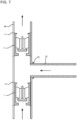
- Fig. 7 is a cross-sectional view showing a state where a plurality of check valve units according to Embodiment 1 of the present disclosure are mounted in a refrigerant pipe.
- Embodiment 6 differs from Embodiment 1 in that a plurality of check valve units 1 according to Embodiment 1 are mounted in one refrigerant pipe 10.
- the check valve unit 1 according to Embodiment 6 is identical to the check valve unit 1 according to Embodiment 1 and hence, the description of the check valve unit 1 according to Embodiment 6 is omitted, and the description will be made mainly for a point that makes the check valve unit 1 according to Embodiment 6 different from the check valve unit 1 according to Embodiment 1.
- Embodiment 6 two check valve units 1 are mounted in series in one refrigerant pipe 10.
- An opening port 13 is formed in the refrigerant pipe 10 by burring or other processing at a position between the check valve units 1, and a refrigerant pipe 12 is connected to the opening port 13 by brazing or other methods.
- the check valve unit according to the present disclosure is reduced in size, thus allowing mounting of the check valve unit at any desired position in a refrigeration cycle. Therefore, even when a plurality of check valve units are used in combination, the plurality of check valve units as a whole are made compact, thus giving the higher degree of freedom in arrangement than the related-art check valve unit at the time of being mounted on an air-conditioning apparatus.
- Embodiment 6 is directed to the air-conditioning apparatus where the plurality of check valve units are mounted in one refrigerant pipe.
- the check valve unit according to the present disclosure is reduced in size and hence, even when the plurality of check valve units are mounted in one refrigerant pipe, the plurality of check valve units as a whole are made compact, thus giving the higher degree of freedom in arrangement than the related-art check valve unit at the time of being mounted on an air-conditioning apparatus.
- the check valve unit 1 described in Embodiment 1 is used.
- the check valve unit is not limited to such a check valve unit, and the check valve unit of any one of Embodiments 2 to 6 or a check valve unit obtained by combining some check valve units may be used.
- 1, 1a, 1b, 1c, 1d check valve unit
- 2 container body
- 3 valve body
- 4 outer die
- 5 shaft pushing tool
- 10 refrigerant pipe
- 11 protrusion
- 12 refrigerant pipe
- 13 opening port
- 20 tube stock
- 21 valve body housing portion
- 22 valve seat
- 23 protruding portion
- 24 oblique side portion
- 25 cut-away portion
- 26 valve body confining portion
- 27 recessed portion
- 52 pressing portion
- 53 nozzle hole
- w width
- t thickness
Landscapes
- Engineering & Computer Science (AREA)
- General Engineering & Computer Science (AREA)
- Mechanical Engineering (AREA)
- Physics & Mathematics (AREA)
- Thermal Sciences (AREA)
- Check Valves (AREA)
Abstract
Description
- The present disclosure relates to a check valve unit used in a refrigeration cycle of an air-conditioning apparatus, for example, and to a method for manufacturing a check valve unit.
- An air-conditioning apparatus includes a refrigeration cycle through which refrigerant cycles, the refrigeration cycle being formed of a compressor, a condenser, an expansion valve, an evaporator, and the like. In such a refrigeration cycle, a check valve may be further installed to cause refrigerant to flow through the refrigeration cycle only in one direction (see
Patent Literature 1, for example). - Patent Literature 1:
Japanese Unexamined Patent Application Publication No. 2013-44418 - As disclosed in
Patent Literature 1, a related-art check valve includes a large diameter portion, small diameter portions, and tapered portions, the large diameter portion forming a tubular body and housing a valve assembly, the small diameter portions being located on both sides of the large diameter portion and forming an inlet port and an outlet port, the tapered portion being formed between each small diameter portion and the large diameter portion. Therefore, a check valve per se has a long dimension. Particularly, when a plurality of check valves are used in combination, an assembly of the check valves increases in size and hence, there is a problem that restrictions are imposed on the arrangement of the assembly when the assembly is mounted on an air-conditioning apparatus. - The present disclosure has been made to solve the above-mentioned problem, and it is an object of the present disclosure to provide a check valve unit in which minimal restrictions are imposed on the arrangement of the check valve unit due to a reduction in size when the check valve unit is mounted on an air-conditioning apparatus. Solution to Problem
- A check valve unit of an embodiment of the present disclosure includes: a container body including a valve body housing portion, a valve seat, and a protruding portion, the valve body housing portion having a cylindrical shape, the valve seat being formed at one end portion of the valve body housing portion and protruding from an inner peripheral surface of the valve body housing portion, the protruding portion being formed at the other end portion of the valve body housing portion and protruding from the inner peripheral surface of the valve body housing portion; and a valve body including a valve portion and a guide portion and disposed in the container body, the valve portion coming into contact with the valve seat at a time of preventing backflow of refrigerant, the guide portion including a plurality of blades.
- The check valve unit of the embodiment of the present disclosure is reduced in size compared with a related-art check valve, thus giving the higher degree of freedom in arrangement than the related-art check valve unit at the time of being mounted on an air-conditioning apparatus.
-
- [
Fig. 1] Fig. 1 is a cross-sectional view showing a state where a check valve unit according toEmbodiment 1 of the present disclosure is mounted in a refrigerant pipe. - [
Fig. 2a] Fig. 2a is a cross-sectional view showing one of steps of manufacturing the check valve unit according toEmbodiment 1 of the present disclosure. - [
Fig. 2b] Fig. 2b is a cross-sectional view showing one of the steps of manufacturing the check valve unit according toEmbodiment 1 of the present disclosure. - [
Fig. 2c] Fig. 2c is a cross-sectional view showing one of the steps of manufacturing the check valve unit according toEmbodiment 1 of the present disclosure. - [
Fig. 2d] Fig. 2d is a cross-sectional view showing one of the steps of manufacturing the check valve unit according toEmbodiment 1 of the present disclosure. - [
Fig. 2e] Fig. 2e is a cross-sectional view showing one of the steps of manufacturing the check valve unit according toEmbodiment 1 of the present disclosure. - [
Fig. 2f] Fig. 2f is a cross-sectional view showing one of the steps of manufacturing the check valve unit according toEmbodiment 1 of the present disclosure. - [
Fig. 2g] Fig. 2g is a cross-sectional view showing one of the steps of manufacturing the check valve unit according toEmbodiment 1 of the present disclosure. - [
Fig. 3] Fig. 3 is a cross-sectional view of a check valve unit according toEmbodiment 2 of the present disclosure. - [
Fig. 4] Fig. 4 is a cross-sectional view of a check valve unit according toEmbodiment 3 of the present disclosure. - [
Fig. 5] Fig. 5 is a cross-sectional view of a check valve unit according toEmbodiment 4 of the present disclosure. - [
Fig. 6] Fig. 6 is a cross-sectional view showing a state where a check valve unit according toEmbodiment 5 of the present disclosure is mounted in a refrigerant pipe. - [
Fig. 7] Fig. 7 is a cross-sectional view showing a state where a plurality of check valve units according to the present disclosure are mounted in a refrigerant pipe. Description of Embodiments - Hereinafter, a check valve unit and a method for manufacturing a check valve unit according to embodiments of the present disclosure will be described with reference to drawings and the like. In the respective drawings, identical or corresponding components are given the same reference symbols, and the description of such components is omitted or simplified when appropriate. The shapes, the sizes, the arrangement, and the like of the components described in the respective drawings may be suitably changed within the scope of the present disclosure.
-
Fig. 1 is a cross-sectional view showing a state where a check valve unit according toEmbodiment 1 of the present disclosure is mounted in a refrigerant pipe. Acheck valve unit 1 according to the present disclosure is mounted in arefrigerant pipe 10 forming the refrigeration cycle of an air-conditioning apparatus, and has a function of restricting the flow of refrigerant to only one direction by preventing backflow of refrigerant. An example of a method for mounting thecheck valve unit 1 in therefrigerant pipe 10 is that, at positions in front and in rear of where thecheck valve unit 1 is mounted, a plurality ofprotrusions 11 are formed from the outer side of therefrigerant pipe 10 by dimpling or the like to fix thecheck valve unit 1 in therefrigerant pipe 10. For the method for mounting thecheck valve unit 1 in therefrigerant pipe 10, a related-art method may be adopted where drawing is applied to therefrigerant pipe 10 at positions in front and in rear of where thecheck valve unit 1 is mounted. - The
check valve unit 1 includes acontainer body 2 and avalve body 3. Thecontainer body 2 is an inner pipe having a cylindrical shape. Thevalve body 3 is disposed in thecontainer body 2 and is movable in the axial direction. - The
container body 2 is formed of a tube stock made of copper, and forms the body of thecheck valve unit 1. Thecontainer body 2 includes a valvebody housing portion 21, avalve seat 22, and a protrudingportion 23. The valvebody housing portion 21 has a cylindrical shape and houses thevalve body 3. Thevalve seat 22 is formed at one end portion of the valvebody housing portion 21, and protrudes from the inner peripheral surface of the valvebody housing portion 21. The protrudingportion 23 is formed at the other end portion of the valvebody housing portion 21, and protrudes from the inner peripheral surface of the valvebody housing portion 21. - The valve
body housing portion 21 houses thevalve body 3 therein, and has a certain length to allow thevalve body 3 to move in the axial direction according to the flow direction of refrigerant. - The
valve seat 22 is formed at one end portion of the valvebody housing portion 21 in the longitudinal direction, and protrudes from the inner peripheral surface of the valvebody housing portion 21. Thevalve seat 22 forms an inlet for refrigerant when the refrigerant flows through thecheck valve unit 1 as shown by arrows inFig. 1 . Thevalve seat 22 is formed to have an inner diameter smaller than the inner diameter of the valvebody housing portion 21, and is closed by thevalve body 3 at the time of preventing backflow of refrigerant. Thevalve seat 22 is integrally formed with the valvebody housing portion 21 by hydroforming, which will be described later. - The protruding
portion 23 is formed at the other end portion of the valvebody housing portion 21 in the longitudinal direction, and protrudes from the inner peripheral surface of the valvebody housing portion 21. The protrudingportion 23 forms an outlet for refrigerant when the refrigerant flows through thecheck valve unit 1 as shown by the arrows inFig. 1 . The protrudingportion 23 is formed to have an inner diameter smaller than the inner diameter of the valvebody housing portion 21, and has a function of confining thevalve body 3 in the valvebody housing portion 21 when refrigerant flows through thecheck valve unit 1. - The
valve body 3 is disposed between thevalve seat 22 and the protrudingportion 23 in thecontainer body 2, and moves in the axial direction in the valvebody housing portion 21 according to the flow direction of refrigerant. When refrigerant flows from thevalve seat 22 toward the protrudingportion 23, thevalve body 3 moves toward the protrudingportion 23 in the valvebody housing portion 21 to allow the refrigerant to pass through thecheck valve unit 1. - In contrast, when refrigerant flows from the protruding
portion 23 toward thevalve seat 22, thevalve body 3 moves toward the inflow side in the valvebody housing portion 21 and comes into contact with thevalve seat 22, thus preventing the refrigerant from flowing back in thecheck valve unit 1. - The
valve body 3 includes avalve portion 31 and aguide portion 32. Thevalve portion 31 is made of a resin, and comes into contact with thevalve seat 22 at the time of preventing backflow of refrigerant. Theguide portion 32 includes a plurality of blades. Thevalve portion 31 comes into contact with thevalve seat 22 to close the opening port of thevalve seat 22 at the time of preventing refrigerant from flowing back from the protrudingportion 23 toward thevalve seat 22. Theguide portion 32 has a function of guiding thevalve body 3 when thevalve body 3 moves in the axial direction in the valvebody housing portion 21, and the outer diameter of theguide portion 32 is substantially equal to the inner diameter of the valvebody housing portion 21. Theguide portion 32 includes the plurality of blades, and refrigerant flows through between the blades when the refrigerant flows from thevalve seat 22 toward the protrudingportion 23. InEmbodiment 1, theguide portion 32 includes four blades arranged at equal angular intervals of 90 degrees. However, the number of blades is not limited to four. - Next, a method for manufacturing the
check valve unit 1 according toEmbodiment 1 will be described.Fig. 2 is a cross-sectional view showing each of steps of manufacturing thecheck valve unit 1 according toEmbodiment 1 of the present disclosure. - As shown in
Fig. 2a , first, atube stock 20 having a cylindrical shape and forming thecontainer body 2 is disposed in a state of being clamped by outer dies 4. InEmbodiment 1, a hollow pipe made of copper and having a thickness of approximately 1.5 mm is used as thetube stock 20. The reason why copper is adopted as a material for forming thecontainer body 2 is that copper has high workability and high durability, thus being suitable for hydroforming, which will be described later. A material is not limited to copper as long as the material can be worked by hydroforming. - Next, the
tube stock 20 is fixed by pushingshaft pushing tools 5 into thetube stock 20 from both ends of thetube stock 20 as shown inFig. 2b . Eachshaft pushing tool 5 includes aninsertion portion 51, apressing portion 52, and anozzle hole 53. Theinsertion portion 51 is inserted into thetube stock 20. Thepressing portion 52 is pressed against the end surface of thetube stock 20. Fluid, such as water, is fed into thetube stock 20 through thenozzle hole 53. Theinsertion portion 51 has a shape where the outer diameter of theinsertion portion 51 is substantially equal to the inner diameter of thetube stock 20. Therefore, when theinsertion portions 51 of theshaft pushing tools 5 are inserted into thetube stock 20 from both ends of thetube stock 20, the outer surfaces of theinsertion portions 51 are brought into contact with the inner surface of thetube stock 20, and thetube stock 20 is clamped by theinsertion portions 51 and the outer dies 4. In this step, theshaft pushing tools 5 are pushed into thetube stock 20 until thepressing portions 52 are brought into contact with the end surfaces of thetube stock 20. - Next, as shown in
Fig. 2c , thetube stock 20 is filled with fluid, such as water through thenozzle hole 53 to apply internal pressure. Arrows inFig. 2c show a state where fluid passes through the nozzle holes 53 and flows into thetube stock 20. - Next, from a state in the step shown in
Fig. 2b , theshaft pushing tools 5 are further pushed into thetube stock 20 from both ends of thetube stock 20 as shown inFig. 2d while a state is maintained where the inside of thetube stock 20 is filled with fluid. Thetube stock 20 is pushed from both ends by thepressing portions 52 and hence, thetube stock 20 gathers at a portion that is not brought into contact with theinsertion portions 51, so that thevalve seat 22 is formed. At this point of operation, by pushing theshaft pushing tools 5 into thetube stock 20 from both ends in a state where internal pressure is applied to thetube stock 20 from the inside by fluid, thevalve seat 22 can be formed while buckling is prevented. Applying the process by using fluid as described with reference toFig. 2c and Fig. 2d is referred to as hydroforming or the hydroform process. By forming thevalve seat 22 on the inner peripheral surface of thetube stock 20 by hydroforming, it is possible to form the opening port of thevalve seat 22 coaxially with thetube stock 20. With such a configuration, it is possible to suppress leakage of refrigerant that may occur at the time of manufacture or due to deterioration over time. - After the
valve seat 22 is formed, thetube stock 20 is removed from the outer dies 4 and theshaft pushing tools 5 and, as shown inFig. 2e , one side of thetube stock 20 is cut to cause thevalve seat 22 to form one end portion. InEmbodiment 1, the tube stock is cut off from the base of thevalve seat 22. However, the tube stock may also be cut off from an intermediate portion of thevalve seat 22 provided that thevalve seat 22 can ensure a required width w. For example, when a valve seat having a width 2w or more is formed in the above-mentioned step of forming thevalve seat 22 by pushing theshaft pushing tools 5 into thetube stock 20 from both ends of thetube stock 20 and when the formed valve seat is then cut at the center, it is possible to form atube stock 20 including twovalve seats 22 at one time. In this case, wasted portions are not formed when the tube stock is cut and hence, it is possible to reduce a material cost. - After the one side of the
tube stock 20 is cut off, as shown inFig. 2f , thevalve body 3 is inserted into thetube stock 20 with thevalve portion 31 being inserted first. - Lastly, as shown in
Fig. 2g , the protrudingportion 23 protruding inward is formed on thetube stock 20 at the other end portion, the other end portion being on a side opposite to thevalve seat 22. For a method for forming the protrudingportion 23, it is sufficient to adopt a method that causes the end portion of a pipe to protrude inward. An example of such a method includes terminal processing where a rotating roller is caused to come into contact with thetube stock 20 from the outside and pressure is applied to thetube stock 20, thus drawing thetube stock 20 inward. By performing the manufacturing steps shown inFig. 2a to Fig. 2g as described above, thecheck valve unit 1 according toEmbodiment 1 is obtained. - The
check valve unit 1 according to the present disclosure includes neither the small diameter portions nor the tapered portions that are included in the related-art check valve, the small diameter portions forming the inlet port and the outlet port, each tapered portion being formed between the small diameter portion and the large diameter portion. Therefore, in the above-mentioned manufacturing method, thecheck valve unit 1 according to the present disclosure can be reduced in size. Further, thevalve seat 22 is integrally formed with the valvebody housing portion 21 by hydroforming and hence, thecheck valve unit 1 can be formed of two components, that is, thecontainer body 2 and thevalve body 3. Compared with the related-art check valve, thecheck valve unit 1 can reduce the number of parts and can simplify manufacturing steps, thus achieving a reduction in manufacturing cost. - A width w and a thickness t of the
valve seat 22 can be adjusted by the degree at which theshaft pushing tools 5 are pushed into thetube stock 20 and by the length of theinsertion portion 51 of eachshaft pushing tool 5. The width w of thevalve seat 22 is equal to a separation between the distal ends of theinsertion portions 51 of twoshaft pushing tools 5 when theshaft pushing tools 5 are pushed into thetube stock 20 as shown inFig. 2d . The thickness t of thevalve seat 22 is determined based on the width w and the degree at which theshaft pushing tools 5 are pushed into thetube stock 20 in the step shown inFig. 2d . In other words, the volume of thetube stock 20 does not change between before and after the step shown inFig. 2d . Therefore, thetube stock 20 gathers at a portion that is not brought into contact with theinsertion portions 51 by an amount corresponding to the degree at which theshaft pushing tools 5 are pushed into thetube stock 20, so that thevalve seat 22 is formed. Accordingly, the width w and the thickness t of thevalve seat 22 can be adjusted by the degree at which theshaft pushing tools 5 are pushed into thetube stock 20 and by the length of theinsertion portion 51 of eachshaft pushing tool 5. - In the above-mentioned
Embodiment 1, the step shown inFig. 2d of further pushing theshaft pushing tools 5 into thetube stock 20 from both ends of thetube stock 20 is performed after the step shown inFig. 2c of filling thetube stock 20 with fluid. However, the order of steps is not limited to such an order. It is sufficient to prevent a case where theshaft pushing tools 5 are pushed into thetube stock 20 from both ends of thetube stock 20 without applying pressure to thetube stock 20 from the inside. For example, the step of filling thetube stock 20 with fluid may be performed simultaneously with the step of further pushing theshaft pushing tools 5 into thetube stock 20 from both ends of thetube stock 20. - The
check valve unit 1 manufactured by the above-mentioned manufacturing method is mounted in therefrigerant pipe 10 forming the refrigeration cycle of an air-conditioning apparatus as shown inFig. 1 . The air-conditioning apparatus includes a refrigeration cycle including at least a compressor, a condenser, an expansion valve, and an evaporator. Thecheck valve unit 1 can be mounted at any desired position in the refrigeration cycle. Further, thecheck valve unit 1 is reduced in size compared with the related-art check valve, thus giving the higher degree of freedom in arrangement than the related-art check valve unit at the time of being mounted on an air-conditioning apparatus. - As described above, the
check valve unit 1 according toEmbodiment 1 includes thecontainer body 2 and thevalve body 3. Thecontainer body 2 includes the valvebody housing portion 21, thevalve seat 22, and the protrudingportion 23, the valvebody housing portion 21 having a cylindrical shape, thevalve seat 22 being formed at one end portion of the valvebody housing portion 21 and protruding from the inner peripheral surface of the valvebody housing portion 21, the protrudingportion 23 being formed at the other end portion of the valvebody housing portion 21 and protruding from the inner peripheral surface of the valvebody housing portion 21. Thevalve body 3 includes thevalve portion 31 and theguide portion 32, and is disposed in thecontainer body 2, thevalve portion 31 coming into contact with thevalve seat 22 at the time of preventing backflow of refrigerant, theguide portion 32 including a plurality of blades. - With such a configuration, it is possible to achieve a reduction in size compared with the related-art check valve.
- In the
check valve unit 1 according toEmbodiment 1, thevalve seat 22 is integrally formed with the valvebody housing portion 21 by hydroforming. Compared with the related-art check valve, such a configuration can reduce the number of parts and can simplify manufacturing steps, thus achieving a reduction in manufacturing cost. - The method for manufacturing the
check valve unit 1 according toEmbodiment 1 includes the step of disposing thetube stock 20 in a state of being clamped by the outer dies 4, the step of fixing thetube stock 20 by pushing theshaft pushing tools 5 into thetube stock 20 from both ends of thetube stock 20, the step of filling thetube stock 20 with fluid, the step of forming thevalve seat 22 on the inner peripheral surface of thetube stock 20 by further pushing theshaft pushing tools 5 into thetube stock 20 from both ends of thetube stock 20, the step of cutting thetube stock 20 to cause thevalve seat 22 to form one end portion, the step of inserting thevalve body 3 into thetube stock 20, and the step of forming the protrudingportion 23 protruding inward at the other end portion, the other end portion being on a side opposite to thevalve seat 22. - The
check valve unit 1 manufactured by such a manufacturing method includes neither the small diameter portions nor the tapered portions that are included in the related-art check valve, the small diameter portions forming the inlet port and the outlet port, the tapered portion being formed between each small diameter portion and the large diameter portion. Therefore, thecheck valve unit 1 can be reduced in size. Further, thevalve seat 22 is integrally formed with the valvebody housing portion 21 by hydroforming and hence, thecheck valve unit 1 can be formed by two components, that is, thecontainer body 2 and thevalve body 3. Compared with the related-art check valve, thecheck valve unit 1 can reduce the number of parts and can simplify manufacturing steps, thus achieving a reduction in manufacturing cost. - In the method for manufacturing the
check valve unit 1 according toEmbodiment 1, eachshaft pushing tool 5 includes theinsertion portion 51, thepressing portion 52, and thenozzle hole 53. Theinsertion portion 51 is inserted into thetube stock 20. Thepressing portion 52 is pressed against the end surface of thetube stock 20. Fluid is fed into thetube stock 20 through thenozzle hole 53. Theinsertion portion 51 has a shape where the outer diameter of theinsertion portion 51 is substantially equal to the inner diameter of thetube stock 20. With such a manufacturing method, thevalve seat 22 can be integrally formed with the valvebody housing portion 21 by hydroforming. - In the method for manufacturing the
check valve unit 1 according toEmbodiment 1, the step of filling thetube stock 20 with fluid is performed simultaneously with the step of forming thevalve seat 22 on the inner peripheral surface of thetube stock 20 by further pushing theshaft pushing tools 5 into thetube stock 20 from both ends of thetube stock 20. With such a manufacturing method, thevalve seat 22 can be formed while buckling is prevented. - A check valve unit of
Embodiment 2 of the present disclosure will be described.Fig. 3 is a cross-sectional view of the check valve unit according toEmbodiment 2 of the present disclosure. A check valve unit 1a ofEmbodiment 2 differs from thecheck valve unit 1 ofEmbodiment 1 in that thevalve seat 22 has anoblique side portion 24 obtained by cutting off an outer corner that does not come into contact with thevalve body 3. In the description for the check valve unit 1a according toEmbodiment 2, components identical to the corresponding components of thecheck valve unit 1 according toEmbodiment 1 are given the same reference symbols, and the description of such components is omitted. The description will be made mainly for a point that makes the check valve unit 1a according toEmbodiment 2 different from thecheck valve unit 1 according toEmbodiment 1. - The
valve seat 22 ofEmbodiment 2 has theoblique side portion 24 obtained by cutting off the outer corner that does not come into contact with thevalve body 3. By cutting off the outer corner of thevalve seat 22 as described above to form a slope such that the diameter of an opening port, which is an inlet for refrigerant, gradually reduces, it is possible to reduce pressure loss when refrigerant flows into the check valve unit 1a. - For a method for forming the
oblique side portion 24 on thevalve seat 22, a related-art method may be adopted where an outer corner that does not come into contact with thevalve body 3 is cut off or shaved off. It is sufficient to perform, after the step of cutting thetube stock 20 to cause thevalve seat 22 to form one end portion, the step of forming theoblique side portion 24 by cutting off the outer corner of thevalve seat 22 that does not come into contact with thevalve body 3. - As described above, the valve seat of the check valve unit 1a according to
Embodiment 2 has theoblique side portion 24 obtained by cutting off the outer corner that does not come into contact with thevalve body 3. With such a configuration, it is possible to reduce pressure loss when refrigerant flows into thecheck valve unit 1. - A check valve unit of
Embodiment 3 of the present disclosure will be described.Fig. 4 is a cross-sectional view of the check valve unit according toEmbodiment 3 of the present disclosure. Acheck valve unit 1b ofEmbodiment 3 differs from thecheck valve unit 1 ofEmbodiment 1 in that thevalve seat 22 has a cut-awayportion 25 obtained by cutting off an inner corner that comes into contact with thevalve body 3. In the description for thecheck valve unit 1b according toEmbodiment 3, components identical to the corresponding components of thecheck valve unit 1 according toEmbodiment 1 are given the same reference symbols, and the description of such components is omitted. The description will be made mainly for a point that makes thecheck valve unit 1b according toEmbodiment 3 different from thecheck valve unit 1 according toEmbodiment 1. - The
valve seat 22 ofEmbodiment 3 has the cut-awayportion 25 obtained by cutting off the inner corner that comes into contact with thevalve body 3. The cut-awayportion 25 is formed such that the portion that comes into contact with thevalve portion 31 at the time of preventing backflow of refrigerant has a highly accurate roundness. By cutting off the inner corner of thevalve seat 22 as described above, it is possible to reduce a gap formed between thevalve seat 22 and thevalve body 3 at the time of preventing backflow of refrigerant and hence, leakage of refrigerant can be reduced. - For a method for forming the cut-away
portion 25 on thevalve seat 22, a related-art method may be adopted where an inner corner that comes into contact with thevalve body 3 is cut off or shaved off. It is sufficient to perform, after the step of cutting thetube stock 20 to cause thevalve seat 22 to form one end portion, the step of forming the cut-awayportion 25 by cutting off the inner corner of thevalve seat 22 that comes into contact with thevalve body 3. - As described above, the
valve seat 22 of thecheck valve unit 1b according toEmbodiment 3 has the cut-awayportion 25 obtained by cutting off the inner corner that comes into contact with thevalve body 3. The cut-awayportion 25 is formed such that the portion that comes into contact with thevalve portion 31 at the time of preventing backflow of refrigerant has a highly accurate roundness. With such a configuration, it is possible to reduce a gap formed between thevalve seat 22 and thevalve body 3 at the time of preventing backflow of refrigerant and hence, leakage of refrigerant can be reduced. - A check valve unit of
Embodiment 4 of the present disclosure will be described.Fig. 5 is a cross-sectional view of the check valve unit according toEmbodiment 4 of the present disclosure. Acheck valve unit 1c ofEmbodiment 4 differs from thecheck valve unit 1 ofEmbodiment 1 in that thecheck valve unit 1c further includes a valvebody confining portion 26 that confines thevalve body 3 when refrigerant flows. In the description for thecheck valve unit 1c according toEmbodiment 4, components identical to the corresponding components of thecheck valve unit 1 according toEmbodiment 1 are given the same reference symbols, and the description of such components is omitted. The description will be made mainly for a point that makes thecheck valve unit 1c according toEmbodiment 4 different from thecheck valve unit 1 according toEmbodiment 1. - The
check valve unit 1c ofEmbodiment 4 further includes the valvebody confining portion 26 provided on the inner peripheral surface of the valvebody housing portion 21 at a position in contact with the protrudingportion 23 and configured to confine thevalve body 3 when refrigerant flows. In each of the check valve units ofEmbodiments 1 to 3, thevalve body 3 is confined in the valvebody housing portion 21 by the protrudingportion 23 when refrigerant flows through the check valve unit. In the case of such a configuration, thevalve body 3 collides with the protrudingportion 23 made of metal, thus causing a large impact sound. In view of the above, the valvebody confining portion 26 that confines thevalve body 3 when refrigerant flows is additionally mounted. With such a configuration, it is possible to suppress an impact sound caused when thevalve body 3 collides with the valvebody confining portion 26. By using a resin material, such as polyphenylene sulfide (PPS), polyacetal (POM), or nylon, as a material for forming the valvebody confining portion 26, impact sound can be suppressed. - For a method for mounting the valve
body confining portion 26, a method is adopted where, after thevalve body 3 is inserted into the tube stock, the valvebody confining portion 26 is mounted on the inner peripheral surface of the tube stock by welding or other methods at a position on a side opposite to thevalve seat 22 as viewed from thevalve body 3. Alternatively, a method may be adopted where the valvebody confining portion 26 is fixed by forming a step portion by shaving the inner peripheral surface of the tube stock. After the valvebody confining portion 26 is mounted in the tube stock, the protrudingportion 23 is formed to be in contact with the valvebody confining portion 26. - As described above, the
check valve unit 1c according toEmbodiment 4 further includes the valvebody confining portion 26 provided on the inner peripheral surface of the valvebody housing portion 21 at a position in contact with the protrudingportion 23 and configured to confine thevalve body 3 when refrigerant flows. With such a configuration, when refrigerant flows through thecheck valve unit 1c, thevalve body 3 is confined by the valvebody confining portion 26 instead of the protrudingportion 23 and hence, it is possible to improve durability of a component. - A check valve unit of
Embodiment 5 of the present disclosure will be described.Fig. 6 is a cross-sectional view showing a state where the check valve unit according toEmbodiment 5 of the present disclosure is mounted in a refrigerant pipe. Acheck valve unit 1d ofEmbodiment 5 differs from thecheck valve unit 1 ofEmbodiment 1 in that the outer peripheral surface of thevalve seat 22 of thecontainer body 2 has a recessedportion 27 into which a ring-shaped resin is inserted. In the description for thecheck valve unit 1d according toEmbodiment 5, components identical to the corresponding components of thecheck valve unit 1 according toEmbodiment 1 are given the same reference symbols, and the description of such components is omitted. The description will be made mainly for a point that makes thecheck valve unit 1d according toEmbodiment 5 different from thecheck valve unit 1 according toEmbodiment 1. - In the
container body 2 of thecheck valve unit 1d ofEmbodiment 5, the outer peripheral surface of thevalve seat 22 has the recessedportion 27 into which a ring-shaped resin is inserted. By inserting the ring-shaped resin into the recessedportion 27 when thecheck valve unit 1d is mounted in therefrigerant pipe 10, it is possible to suppress refrigerant flowing through a gap formed between thecheck valve unit 1d and therefrigerant pipe 10. The recessedportion 27 is formed on the outer peripheral surface of thevalve seat 22 having a larger thickness than the valvebody housing portion 21 and hence, there is no possibility for reduction in the strength of thecontainer body 2. - For a method for forming the recessed portion on the outer peripheral surface of the
valve seat 22 of thecontainer body 2, a related-art method, such as shaving, may be adopted. It is sufficient to perform the step of forming the recessed portion after the step of forming thevalve seat 22 on the inner peripheral surface of thetube stock 20 by hydroforming. - As described above, in the valve seat of the
check valve unit 1d according toEmbodiment 5, the outer peripheral surface of thevalve seat 22 of thecontainer body 2 has the recessedportion 27 into which a ring-shaped resin is inserted. With such a configuration, by mounting thecheck valve unit 1d in therefrigerant pipe 10 with the ring-shaped resin being inserted into the recessedportion 27, it is possible to suppress refrigerant flowing through a gap formed between thecheck valve unit 1d and therefrigerant pipe 10. - Embodiment 6 of the present disclosure will be described.
Fig. 7 is a cross-sectional view showing a state where a plurality of check valve units according toEmbodiment 1 of the present disclosure are mounted in a refrigerant pipe. Embodiment 6 differs fromEmbodiment 1 in that a plurality ofcheck valve units 1 according toEmbodiment 1 are mounted in onerefrigerant pipe 10. Thecheck valve unit 1 according to Embodiment 6 is identical to thecheck valve unit 1 according toEmbodiment 1 and hence, the description of thecheck valve unit 1 according to Embodiment 6 is omitted, and the description will be made mainly for a point that makes thecheck valve unit 1 according to Embodiment 6 different from thecheck valve unit 1 according toEmbodiment 1. - In Embodiment 6, two
check valve units 1 are mounted in series in onerefrigerant pipe 10. Anopening port 13 is formed in therefrigerant pipe 10 by burring or other processing at a position between thecheck valve units 1, and arefrigerant pipe 12 is connected to theopening port 13 by brazing or other methods. The check valve unit according to the present disclosure is reduced in size, thus allowing mounting of the check valve unit at any desired position in a refrigeration cycle. Therefore, even when a plurality of check valve units are used in combination, the plurality of check valve units as a whole are made compact, thus giving the higher degree of freedom in arrangement than the related-art check valve unit at the time of being mounted on an air-conditioning apparatus. Further, in the case of forming an assembly by using a plurality of related-art check valves, joint pipes are used between the check valves and hence, the number of portions where brazing is applied increases. However, when the check valve units of the present disclosure are used, it is possible to reduce the number of portions where brazing is applied. For a method for mounting thecheck valve unit 1 in therefrigerant pipe 10, the method described inEmbodiment 1 may be adopted. - As described above, Embodiment 6 is directed to the air-conditioning apparatus where the plurality of check valve units are mounted in one refrigerant pipe. The check valve unit according to the present disclosure is reduced in size and hence, even when the plurality of check valve units are mounted in one refrigerant pipe, the plurality of check valve units as a whole are made compact, thus giving the higher degree of freedom in arrangement than the related-art check valve unit at the time of being mounted on an air-conditioning apparatus.
- In Embodiment 6, the
check valve unit 1 described inEmbodiment 1 is used. However, the check valve unit is not limited to such a check valve unit, and the check valve unit of any one ofEmbodiments 2 to 6 or a check valve unit obtained by combining some check valve units may be used. - The present disclosure has been described heretofore by using the above-mentioned Embodiments. However, some of these Embodiments may be performed in combination. Further, the technical scope of the present disclosure is not limited to the scope described in the above-mentioned Embodiments. Various changes or modifications may be applied to each of the above-mentioned Embodiments without departing from the gist of the disclosure, and Embodiments to which such changes or modifications are applied also fall within the technical scope of the present disclosure.
- 1, 1a, 1b, 1c, 1d: check valve unit, 2: container body, 3: valve body, 4: outer die, 5: shaft pushing tool, 10: refrigerant pipe, 11: protrusion, 12: refrigerant pipe, 13: opening port, 20: tube stock, 21: valve body housing portion, 22: valve seat, 23: protruding portion, 24: oblique side portion, 25: cut-away portion, 26: valve body confining portion, 27: recessed portion, 31: valve portion, 32: guide portion, 51: insertion portion, 52: pressing portion, 53: nozzle hole, w: width, t: thickness
Claims (14)
- A check valve unit comprising:a container body including a valve body housing portion, a valve seat, and a protruding portion, the valve body housing portion having a cylindrical shape, the valve seat being formed at one end portion of the valve body housing portion and protruding from an inner peripheral surface of the valve body housing portion, the protruding portion being formed at an other end portion of the valve body housing portion and protruding from the inner peripheral surface of the valve body housing portion; anda valve body including a valve portion and a guide portion and disposed in the container body, the valve portion coming into contact with the valve seat at a time of preventing backflow of refrigerant, the guide portion including a plurality of blades.
- The check valve unit of claim 1, wherein the valve seat is integrally formed with the valve body housing portion by hydroforming.
- The check valve unit of claim 1 or claim 2, wherein the valve seat has an oblique side portion obtained by cutting off an outer corner that does not come into contact with the valve body.
- The check valve unit of any one of claims 1 to 3, further comprising a valve body confining portion provided on the inner peripheral surface of the valve body housing portion at a position in contact with the protruding portion, and configured to confine the valve body when refrigerant flows.
- The check valve unit of any one of claims 1 to 4, wherein an outer peripheral surface of the valve seat of the container body has a recessed portion into which a ring-shaped resin is inserted.
- An air-conditioning apparatus where the check valve unit of any one of claims 1 to 5 is mounted in a refrigerant pipe.
- An air-conditioning apparatus where a plurality of the check valve units of any one of claims 1 to 5 are mounted in one refrigerant pipe.
- A method for manufacturing a check valve unit, the method comprising:disposing a tube stock in a state of being clamped by outer dies;fixing the tube stock by pushing shaft pushing tools into the tube stock from both ends of the tube stock;filling the tube stock with fluid;forming a valve seat on an inner peripheral surface of the tube stock by further pushing the shaft pushing tools into the tube stock from both ends of the tube stock;cutting the tube stock to cause the valve seat to form one end portion;inserting a valve body into the tube stock; andforming a protruding portion that protrudes inward at an other end portion, the other end portion being on a side opposite to the valve seat.
- The method for manufacturing a check valve unit of claim 8, further comprising forming an oblique side portion by cutting off an outer corner of the valve seat that does not come into contact with the valve body.
- The method for manufacturing a check valve unit of claim 8 or claim 9, comprising, between the inserting the valve body into the tube stock and the forming the protruding portion, mounting a valve body confining portion on the inner peripheral surface of the tube stock at a position on the side opposite to the valve seat as viewed from the valve body, wherein
the valve body confining portion is in contact with the protruding portion, and is provided between the protruding portion and the valve body. - The method for manufacturing a check valve unit of any one of claims 8 to 10, further comprising forming a recessed portion on an outer peripheral surface of the valve seat, a ring-shaped resin being inserted into the recessed portion.
- The method for manufacturing a check valve unit of any one of claims 8 to 11, wherein each of the shaft pushing tools includes an insertion portion, a pressing portion, and a nozzle hole, the insertion portion being inserted into the tube stock, the pressing portion being pressed against an end surface of the tube stock, fluid being fed into the tube stock through the nozzle hole.
- The method for manufacturing a check valve unit of claim 12, wherein the insertion portion has a shape where an outer diameter of the insertion portion is substantially equal to an inner diameter of the tube stock.
- The method for manufacturing a check valve unit of any one of claims 8 to 13, wherein the filling the tube stock with fluid is performed simultaneously with the forming the valve seat on the inner peripheral surface of the tube stock by further pushing the shaft pushing tools into the tube stock from both ends of the tube stock.
Applications Claiming Priority (1)
| Application Number | Priority Date | Filing Date | Title |
|---|---|---|---|
| PCT/JP2020/014510 WO2021199139A1 (en) | 2020-03-30 | 2020-03-30 | Check valve unit, air conditioner, and method for manufacturing check valve unit |
Publications (3)
| Publication Number | Publication Date |
|---|---|
| EP4130533A1 true EP4130533A1 (en) | 2023-02-08 |
| EP4130533A4 EP4130533A4 (en) | 2023-05-24 |
| EP4130533B1 EP4130533B1 (en) | 2024-07-10 |
Family
ID=77927991
Family Applications (1)
| Application Number | Title | Priority Date | Filing Date |
|---|---|---|---|
| EP20929333.1A Active EP4130533B1 (en) | 2020-03-30 | 2020-03-30 | Method for manufacturing check valve unit |
Country Status (5)
| Country | Link |
|---|---|
| US (1) | US11879556B2 (en) |
| EP (1) | EP4130533B1 (en) |
| JP (2) | JP7305035B2 (en) |
| CN (1) | CN218510248U (en) |
| WO (1) | WO2021199139A1 (en) |
Families Citing this family (3)
| Publication number | Priority date | Publication date | Assignee | Title |
|---|---|---|---|---|
| EP3951223B1 (en) * | 2019-03-28 | 2026-04-29 | Mitsubishi Electric Corporation | Check valve manufacturing method |
| US11879556B2 (en) * | 2020-03-30 | 2024-01-23 | Mitsubishi Electric Corporation | Check valve unit and air-conditioning apparatus, and method for manufacturing check valve unit |
| JP7361946B2 (en) * | 2020-11-16 | 2023-10-16 | 三菱電機株式会社 | non-return valve |
Family Cites Families (22)
| Publication number | Priority date | Publication date | Assignee | Title |
|---|---|---|---|---|
| US3157191A (en) * | 1961-04-21 | 1964-11-17 | Diexell Dev And Mfg Company | Rotating cylinder guided check-valve assembly |
| JPS59163270U (en) * | 1983-04-15 | 1984-11-01 | 鈴木 茂 | Valve body for check valve |
| USD318098S (en) * | 1988-05-31 | 1991-07-09 | The Hotsy Corporation | Valve check member |
| US5154589A (en) * | 1990-11-09 | 1992-10-13 | National Instrument Company | Metering pump |
| JPH10238640A (en) * | 1997-02-28 | 1998-09-08 | Sanpo Shindo Kogyo Kk | Pipe type check valve |
| JP2001324037A (en) * | 2000-05-12 | 2001-11-22 | Bosch Braking Systems Co Ltd | Check valve with variable throttle and method of manufacturing the same |
| JP3811020B2 (en) | 2001-05-23 | 2006-08-16 | 株式会社栗本鐵工所 | Butterfly valve and method for manufacturing the butterfly valve |
| JP3794680B2 (en) * | 2001-11-19 | 2006-07-05 | 本田技研工業株式会社 | Hydroforming method |
| JP2006046538A (en) | 2004-08-05 | 2006-02-16 | Daikin Ind Ltd | Refrigerant piping structure |
| JP2006046539A (en) * | 2004-08-05 | 2006-02-16 | Daikin Ind Ltd | Check valve |
| USD576704S1 (en) * | 2006-06-12 | 2008-09-09 | Neoperl Gmbh | Sanitary check valve |
| JP5774943B2 (en) * | 2011-08-26 | 2015-09-09 | 株式会社不二工機 | Check valve device |
| JP5783073B2 (en) * | 2012-02-06 | 2015-09-24 | 新日鐵住金株式会社 | Hydroform processing method |
| USD725747S1 (en) * | 2013-12-23 | 2015-03-31 | Fna Ip Holdings, Inc. | Valve |
| USD728072S1 (en) * | 2013-12-23 | 2015-04-28 | FNA IP Holdings, Inc | Valve |
| JP6560499B2 (en) | 2015-01-28 | 2019-08-14 | 日電工業株式会社 | Check valve manufacturing method and check valve manufactured by the manufacturing method |
| JP2019039541A (en) | 2017-08-29 | 2019-03-14 | 日本電産トーソク株式会社 | Hydraulic control device |
| CN109720327B (en) * | 2017-10-20 | 2022-08-02 | 株式会社万都 | Check valve |
| EP3951223B1 (en) * | 2019-03-28 | 2026-04-29 | Mitsubishi Electric Corporation | Check valve manufacturing method |
| CN209743160U (en) * | 2019-04-24 | 2019-12-06 | 广东美芝制冷设备有限公司 | Rotary compressors and refrigeration cycle units |
| DE102019135310A1 (en) * | 2019-12-19 | 2021-06-24 | Otto Egelhof Gmbh & Co. Kg | Check valve and connection device for a check valve |
| US11879556B2 (en) * | 2020-03-30 | 2024-01-23 | Mitsubishi Electric Corporation | Check valve unit and air-conditioning apparatus, and method for manufacturing check valve unit |
-
2020
- 2020-03-30 US US17/796,445 patent/US11879556B2/en active Active
- 2020-03-30 JP JP2022512887A patent/JP7305035B2/en active Active
- 2020-03-30 WO PCT/JP2020/014510 patent/WO2021199139A1/en not_active Ceased
- 2020-03-30 CN CN202090001119.XU patent/CN218510248U/en not_active Expired - Fee Related
- 2020-03-30 EP EP20929333.1A patent/EP4130533B1/en active Active
-
2023
- 2023-04-25 JP JP2023071677A patent/JP7471489B2/en active Active
Also Published As
| Publication number | Publication date |
|---|---|
| US11879556B2 (en) | 2024-01-23 |
| CN218510248U (en) | 2023-02-21 |
| WO2021199139A1 (en) | 2021-10-07 |
| US20230160481A1 (en) | 2023-05-25 |
| EP4130533B1 (en) | 2024-07-10 |
| JP7471489B2 (en) | 2024-04-19 |
| EP4130533A4 (en) | 2023-05-24 |
| JP7305035B2 (en) | 2023-07-07 |
| JPWO2021199139A1 (en) | 2021-10-07 |
| JP2023093690A (en) | 2023-07-04 |
Similar Documents
| Publication | Publication Date | Title |
|---|---|---|
| US11879556B2 (en) | Check valve unit and air-conditioning apparatus, and method for manufacturing check valve unit | |
| US6928732B2 (en) | Method of manufacturing piping having joining portion | |
| EP3951223B1 (en) | Check valve manufacturing method | |
| US6053243A (en) | Header pipe for heat exchanger and manufacturing apparatus and manufacturing method thereof | |
| JP5774943B2 (en) | Check valve device | |
| EP3828450B1 (en) | Electric valve | |
| US12400627B2 (en) | Sound reducer, method of making same, and fluid conduit system including such a sound reducer | |
| US7926854B2 (en) | Pipe joint block for fluid transfer | |
| US20070266730A1 (en) | Refrigerant Distributor and Method for Manufacturing the Same | |
| EP3991873A1 (en) | Flow path structure, check valve comprising same, and method for producing check valve | |
| JP2006132653A (en) | Double pipe, double pipe manufacturing method, double pipe support member | |
| JP3956878B2 (en) | Piping joint structure and piping joint connection method | |
| KR20140112751A (en) | Muffler manufacturing method for car air conditioning system and muffler thereof | |
| CN116928405A (en) | Method for manufacturing one-way valve and one-way valve | |
| JP2007225117A (en) | Double tube structure | |
| JPH1061424A (en) | Noise eliminator and its manufacture | |
| KR100875762B1 (en) | Receiver drier tank of automobile heat exchanger and its forming apparatus and forming method | |
| EP3786500A1 (en) | Solenoid valve, armature tube and armature top for a solenoid valve | |
| KR100494064B1 (en) | Check valve and it's manufacturing method | |
| CN218440827U (en) | One-way valve | |
| KR100855707B1 (en) | Receiver dryer tank, manufacturing method and manufacturing apparatus | |
| KR20240111497A (en) | Method for manufacturing a heat-exchanging double pipe | |
| CN115727159A (en) | Reversing valve | |
| JP2023035369A (en) | Manufacturing method of three-way pipe unit, three-way pipe unit and check valve bridge refrigerant circuit module | |
| JP2010207890A (en) | Method for producing connecting member |
Legal Events
| Date | Code | Title | Description |
|---|---|---|---|
| STAA | Information on the status of an ep patent application or granted ep patent |
Free format text: STATUS: THE INTERNATIONAL PUBLICATION HAS BEEN MADE |
|
| PUAI | Public reference made under article 153(3) epc to a published international application that has entered the european phase |
Free format text: ORIGINAL CODE: 0009012 |
|
| STAA | Information on the status of an ep patent application or granted ep patent |
Free format text: STATUS: REQUEST FOR EXAMINATION WAS MADE |
|
| 17P | Request for examination filed |
Effective date: 20220926 |
|
| AK | Designated contracting states |
Kind code of ref document: A1 Designated state(s): AL AT BE BG CH CY CZ DE DK EE ES FI FR GB GR HR HU IE IS IT LI LT LU LV MC MK MT NL NO PL PT RO RS SE SI SK SM TR |
|
| A4 | Supplementary search report drawn up and despatched |
Effective date: 20230425 |
|
| RIC1 | Information provided on ipc code assigned before grant |
Ipc: F16K 15/06 20060101ALI20230419BHEP Ipc: F16K 15/02 20060101AFI20230419BHEP |
|
| DAV | Request for validation of the european patent (deleted) | ||
| DAX | Request for extension of the european patent (deleted) | ||
| GRAP | Despatch of communication of intention to grant a patent |
Free format text: ORIGINAL CODE: EPIDOSNIGR1 |
|
| STAA | Information on the status of an ep patent application or granted ep patent |
Free format text: STATUS: GRANT OF PATENT IS INTENDED |
|
| INTG | Intention to grant announced |
Effective date: 20240213 |
|
| GRAS | Grant fee paid |
Free format text: ORIGINAL CODE: EPIDOSNIGR3 |
|
| GRAA | (expected) grant |
Free format text: ORIGINAL CODE: 0009210 |
|
| STAA | Information on the status of an ep patent application or granted ep patent |
Free format text: STATUS: THE PATENT HAS BEEN GRANTED |
|
| AK | Designated contracting states |
Kind code of ref document: B1 Designated state(s): AL AT BE BG CH CY CZ DE DK EE ES FI FR GB GR HR HU IE IS IT LI LT LU LV MC MK MT NL NO PL PT RO RS SE SI SK SM TR |
|
| REG | Reference to a national code |
Ref country code: CH Ref legal event code: EP |
|
| REG | Reference to a national code |
Ref country code: DE Ref legal event code: R096 Ref document number: 602020033934 Country of ref document: DE |
|
| REG | Reference to a national code |
Ref country code: LT Ref legal event code: MG9D |
|
| REG | Reference to a national code |
Ref country code: NL Ref legal event code: MP Effective date: 20240710 |
|
| PG25 | Lapsed in a contracting state [announced via postgrant information from national office to epo] |
Ref country code: PT Free format text: LAPSE BECAUSE OF FAILURE TO SUBMIT A TRANSLATION OF THE DESCRIPTION OR TO PAY THE FEE WITHIN THE PRESCRIBED TIME-LIMIT Effective date: 20241111 |
|
| REG | Reference to a national code |
Ref country code: AT Ref legal event code: MK05 Ref document number: 1702286 Country of ref document: AT Kind code of ref document: T Effective date: 20240710 |
|
| PG25 | Lapsed in a contracting state [announced via postgrant information from national office to epo] |
Ref country code: NL Free format text: LAPSE BECAUSE OF FAILURE TO SUBMIT A TRANSLATION OF THE DESCRIPTION OR TO PAY THE FEE WITHIN THE PRESCRIBED TIME-LIMIT Effective date: 20240710 |
|
| PG25 | Lapsed in a contracting state [announced via postgrant information from national office to epo] |
Ref country code: PT Free format text: LAPSE BECAUSE OF FAILURE TO SUBMIT A TRANSLATION OF THE DESCRIPTION OR TO PAY THE FEE WITHIN THE PRESCRIBED TIME-LIMIT Effective date: 20241111 Ref country code: NL Free format text: LAPSE BECAUSE OF FAILURE TO SUBMIT A TRANSLATION OF THE DESCRIPTION OR TO PAY THE FEE WITHIN THE PRESCRIBED TIME-LIMIT Effective date: 20240710 |
|
| PG25 | Lapsed in a contracting state [announced via postgrant information from national office to epo] |
Ref country code: NO Free format text: LAPSE BECAUSE OF FAILURE TO SUBMIT A TRANSLATION OF THE DESCRIPTION OR TO PAY THE FEE WITHIN THE PRESCRIBED TIME-LIMIT Effective date: 20241010 |
|
| PG25 | Lapsed in a contracting state [announced via postgrant information from national office to epo] |
Ref country code: GR Free format text: LAPSE BECAUSE OF FAILURE TO SUBMIT A TRANSLATION OF THE DESCRIPTION OR TO PAY THE FEE WITHIN THE PRESCRIBED TIME-LIMIT Effective date: 20241011 Ref country code: FI Free format text: LAPSE BECAUSE OF FAILURE TO SUBMIT A TRANSLATION OF THE DESCRIPTION OR TO PAY THE FEE WITHIN THE PRESCRIBED TIME-LIMIT Effective date: 20240710 Ref country code: PL Free format text: LAPSE BECAUSE OF FAILURE TO SUBMIT A TRANSLATION OF THE DESCRIPTION OR TO PAY THE FEE WITHIN THE PRESCRIBED TIME-LIMIT Effective date: 20240710 |
|
| PG25 | Lapsed in a contracting state [announced via postgrant information from national office to epo] |
Ref country code: BG Free format text: LAPSE BECAUSE OF FAILURE TO SUBMIT A TRANSLATION OF THE DESCRIPTION OR TO PAY THE FEE WITHIN THE PRESCRIBED TIME-LIMIT Effective date: 20240710 |
|
| PG25 | Lapsed in a contracting state [announced via postgrant information from national office to epo] |
Ref country code: LV Free format text: LAPSE BECAUSE OF FAILURE TO SUBMIT A TRANSLATION OF THE DESCRIPTION OR TO PAY THE FEE WITHIN THE PRESCRIBED TIME-LIMIT Effective date: 20240710 |
|
| PG25 | Lapsed in a contracting state [announced via postgrant information from national office to epo] |
Ref country code: IS Free format text: LAPSE BECAUSE OF FAILURE TO SUBMIT A TRANSLATION OF THE DESCRIPTION OR TO PAY THE FEE WITHIN THE PRESCRIBED TIME-LIMIT Effective date: 20241110 Ref country code: AT Free format text: LAPSE BECAUSE OF FAILURE TO SUBMIT A TRANSLATION OF THE DESCRIPTION OR TO PAY THE FEE WITHIN THE PRESCRIBED TIME-LIMIT Effective date: 20240710 |
|
| PG25 | Lapsed in a contracting state [announced via postgrant information from national office to epo] |
Ref country code: HR Free format text: LAPSE BECAUSE OF FAILURE TO SUBMIT A TRANSLATION OF THE DESCRIPTION OR TO PAY THE FEE WITHIN THE PRESCRIBED TIME-LIMIT Effective date: 20240710 |
|
| PG25 | Lapsed in a contracting state [announced via postgrant information from national office to epo] |
Ref country code: ES Free format text: LAPSE BECAUSE OF FAILURE TO SUBMIT A TRANSLATION OF THE DESCRIPTION OR TO PAY THE FEE WITHIN THE PRESCRIBED TIME-LIMIT Effective date: 20240710 Ref country code: RS Free format text: LAPSE BECAUSE OF FAILURE TO SUBMIT A TRANSLATION OF THE DESCRIPTION OR TO PAY THE FEE WITHIN THE PRESCRIBED TIME-LIMIT Effective date: 20241010 |
|
| PG25 | Lapsed in a contracting state [announced via postgrant information from national office to epo] |
Ref country code: RS Free format text: LAPSE BECAUSE OF FAILURE TO SUBMIT A TRANSLATION OF THE DESCRIPTION OR TO PAY THE FEE WITHIN THE PRESCRIBED TIME-LIMIT Effective date: 20241010 Ref country code: PL Free format text: LAPSE BECAUSE OF FAILURE TO SUBMIT A TRANSLATION OF THE DESCRIPTION OR TO PAY THE FEE WITHIN THE PRESCRIBED TIME-LIMIT Effective date: 20240710 Ref country code: NO Free format text: LAPSE BECAUSE OF FAILURE TO SUBMIT A TRANSLATION OF THE DESCRIPTION OR TO PAY THE FEE WITHIN THE PRESCRIBED TIME-LIMIT Effective date: 20241010 Ref country code: LV Free format text: LAPSE BECAUSE OF FAILURE TO SUBMIT A TRANSLATION OF THE DESCRIPTION OR TO PAY THE FEE WITHIN THE PRESCRIBED TIME-LIMIT Effective date: 20240710 Ref country code: IS Free format text: LAPSE BECAUSE OF FAILURE TO SUBMIT A TRANSLATION OF THE DESCRIPTION OR TO PAY THE FEE WITHIN THE PRESCRIBED TIME-LIMIT Effective date: 20241110 Ref country code: HR Free format text: LAPSE BECAUSE OF FAILURE TO SUBMIT A TRANSLATION OF THE DESCRIPTION OR TO PAY THE FEE WITHIN THE PRESCRIBED TIME-LIMIT Effective date: 20240710 Ref country code: GR Free format text: LAPSE BECAUSE OF FAILURE TO SUBMIT A TRANSLATION OF THE DESCRIPTION OR TO PAY THE FEE WITHIN THE PRESCRIBED TIME-LIMIT Effective date: 20241011 Ref country code: FI Free format text: LAPSE BECAUSE OF FAILURE TO SUBMIT A TRANSLATION OF THE DESCRIPTION OR TO PAY THE FEE WITHIN THE PRESCRIBED TIME-LIMIT Effective date: 20240710 Ref country code: ES Free format text: LAPSE BECAUSE OF FAILURE TO SUBMIT A TRANSLATION OF THE DESCRIPTION OR TO PAY THE FEE WITHIN THE PRESCRIBED TIME-LIMIT Effective date: 20240710 Ref country code: BG Free format text: LAPSE BECAUSE OF FAILURE TO SUBMIT A TRANSLATION OF THE DESCRIPTION OR TO PAY THE FEE WITHIN THE PRESCRIBED TIME-LIMIT Effective date: 20240710 Ref country code: AT Free format text: LAPSE BECAUSE OF FAILURE TO SUBMIT A TRANSLATION OF THE DESCRIPTION OR TO PAY THE FEE WITHIN THE PRESCRIBED TIME-LIMIT Effective date: 20240710 |
|
| PGFP | Annual fee paid to national office [announced via postgrant information from national office to epo] |
Ref country code: DE Payment date: 20250204 Year of fee payment: 6 |
|
| REG | Reference to a national code |
Ref country code: DE Ref legal event code: R097 Ref document number: 602020033934 Country of ref document: DE |
|
| PG25 | Lapsed in a contracting state [announced via postgrant information from national office to epo] |
Ref country code: DK Free format text: LAPSE BECAUSE OF FAILURE TO SUBMIT A TRANSLATION OF THE DESCRIPTION OR TO PAY THE FEE WITHIN THE PRESCRIBED TIME-LIMIT Effective date: 20240710 Ref country code: SM Free format text: LAPSE BECAUSE OF FAILURE TO SUBMIT A TRANSLATION OF THE DESCRIPTION OR TO PAY THE FEE WITHIN THE PRESCRIBED TIME-LIMIT Effective date: 20240710 Ref country code: RO Free format text: LAPSE BECAUSE OF FAILURE TO SUBMIT A TRANSLATION OF THE DESCRIPTION OR TO PAY THE FEE WITHIN THE PRESCRIBED TIME-LIMIT Effective date: 20240710 |
|
| PG25 | Lapsed in a contracting state [announced via postgrant information from national office to epo] |
Ref country code: EE Free format text: LAPSE BECAUSE OF FAILURE TO SUBMIT A TRANSLATION OF THE DESCRIPTION OR TO PAY THE FEE WITHIN THE PRESCRIBED TIME-LIMIT Effective date: 20240710 |
|
| PG25 | Lapsed in a contracting state [announced via postgrant information from national office to epo] |
Ref country code: CZ Free format text: LAPSE BECAUSE OF FAILURE TO SUBMIT A TRANSLATION OF THE DESCRIPTION OR TO PAY THE FEE WITHIN THE PRESCRIBED TIME-LIMIT Effective date: 20240710 |
|
| PG25 | Lapsed in a contracting state [announced via postgrant information from national office to epo] |
Ref country code: SK Free format text: LAPSE BECAUSE OF FAILURE TO SUBMIT A TRANSLATION OF THE DESCRIPTION OR TO PAY THE FEE WITHIN THE PRESCRIBED TIME-LIMIT Effective date: 20240710 Ref country code: IT Free format text: LAPSE BECAUSE OF FAILURE TO SUBMIT A TRANSLATION OF THE DESCRIPTION OR TO PAY THE FEE WITHIN THE PRESCRIBED TIME-LIMIT Effective date: 20240710 |
|
| PGFP | Annual fee paid to national office [announced via postgrant information from national office to epo] |
Ref country code: GB Payment date: 20250206 Year of fee payment: 6 |
|
| PLBE | No opposition filed within time limit |
Free format text: ORIGINAL CODE: 0009261 |
|
| STAA | Information on the status of an ep patent application or granted ep patent |
Free format text: STATUS: NO OPPOSITION FILED WITHIN TIME LIMIT |
|
| 26N | No opposition filed |
Effective date: 20250411 |
|
| PG25 | Lapsed in a contracting state [announced via postgrant information from national office to epo] |
Ref country code: SE Free format text: LAPSE BECAUSE OF FAILURE TO SUBMIT A TRANSLATION OF THE DESCRIPTION OR TO PAY THE FEE WITHIN THE PRESCRIBED TIME-LIMIT Effective date: 20240710 |
|
| P01 | Opt-out of the competence of the unified patent court (upc) registered |
Free format text: CASE NUMBER: UPC_APP_4946_4130533/2025 Effective date: 20250827 |
|
| PG25 | Lapsed in a contracting state [announced via postgrant information from national office to epo] |
Ref country code: MC Free format text: LAPSE BECAUSE OF FAILURE TO SUBMIT A TRANSLATION OF THE DESCRIPTION OR TO PAY THE FEE WITHIN THE PRESCRIBED TIME-LIMIT Effective date: 20240710 |
|
| REG | Reference to a national code |
Ref country code: CH Ref legal event code: H13 Free format text: ST27 STATUS EVENT CODE: U-0-0-H10-H13 (AS PROVIDED BY THE NATIONAL OFFICE) Effective date: 20251023 |
|
| PG25 | Lapsed in a contracting state [announced via postgrant information from national office to epo] |
Ref country code: LU Free format text: LAPSE BECAUSE OF NON-PAYMENT OF DUE FEES Effective date: 20250330 |
|
| REG | Reference to a national code |
Ref country code: BE Ref legal event code: MM Effective date: 20250331 |
|
| PG25 | Lapsed in a contracting state [announced via postgrant information from national office to epo] |
Ref country code: FR Free format text: LAPSE BECAUSE OF NON-PAYMENT OF DUE FEES Effective date: 20250331 |
|
| PG25 | Lapsed in a contracting state [announced via postgrant information from national office to epo] |
Ref country code: BE Free format text: LAPSE BECAUSE OF NON-PAYMENT OF DUE FEES Effective date: 20250331 |
|
| PG25 | Lapsed in a contracting state [announced via postgrant information from national office to epo] |
Ref country code: CH Free format text: LAPSE BECAUSE OF NON-PAYMENT OF DUE FEES Effective date: 20250331 |
|
| PG25 | Lapsed in a contracting state [announced via postgrant information from national office to epo] |
Ref country code: IE Free format text: LAPSE BECAUSE OF NON-PAYMENT OF DUE FEES Effective date: 20250330 |