EP4130508A1 - Vibration-proof bush - Google Patents
Vibration-proof bush Download PDFInfo
- Publication number
- EP4130508A1 EP4130508A1 EP21780802.1A EP21780802A EP4130508A1 EP 4130508 A1 EP4130508 A1 EP 4130508A1 EP 21780802 A EP21780802 A EP 21780802A EP 4130508 A1 EP4130508 A1 EP 4130508A1
- Authority
- EP
- European Patent Office
- Prior art keywords
- bush
- vibration
- proof
- upper bush
- elastic body
- Prior art date
- Legal status (The legal status is an assumption and is not a legal conclusion. Google has not performed a legal analysis and makes no representation as to the accuracy of the status listed.)
- Pending
Links
Images

Classifications
-
- B—PERFORMING OPERATIONS; TRANSPORTING
- B60—VEHICLES IN GENERAL
- B60K—ARRANGEMENT OR MOUNTING OF PROPULSION UNITS OR OF TRANSMISSIONS IN VEHICLES; ARRANGEMENT OR MOUNTING OF PLURAL DIVERSE PRIME-MOVERS IN VEHICLES; AUXILIARY DRIVES FOR VEHICLES; INSTRUMENTATION OR DASHBOARDS FOR VEHICLES; ARRANGEMENTS IN CONNECTION WITH COOLING, AIR INTAKE, GAS EXHAUST OR FUEL SUPPLY OF PROPULSION UNITS IN VEHICLES
- B60K17/00—Arrangement or mounting of transmissions in vehicles
- B60K17/22—Arrangement or mounting of transmissions in vehicles characterised by arrangement, location, or type of main drive shafting, e.g. cardan shaft
- B60K17/24—Arrangement of mountings for shafting
-
- F—MECHANICAL ENGINEERING; LIGHTING; HEATING; WEAPONS; BLASTING
- F16—ENGINEERING ELEMENTS AND UNITS; GENERAL MEASURES FOR PRODUCING AND MAINTAINING EFFECTIVE FUNCTIONING OF MACHINES OR INSTALLATIONS; THERMAL INSULATION IN GENERAL
- F16F—SPRINGS; SHOCK-ABSORBERS; MEANS FOR DAMPING VIBRATION
- F16F1/00—Springs
- F16F1/36—Springs made of rubber or other material having high internal friction, e.g. thermoplastic elastomers
- F16F1/373—Springs made of rubber or other material having high internal friction, e.g. thermoplastic elastomers characterised by having a particular shape
- F16F1/3732—Springs made of rubber or other material having high internal friction, e.g. thermoplastic elastomers characterised by having a particular shape having an annular or the like shape, e.g. grommet-type resilient mountings
-
- F—MECHANICAL ENGINEERING; LIGHTING; HEATING; WEAPONS; BLASTING
- F16—ENGINEERING ELEMENTS AND UNITS; GENERAL MEASURES FOR PRODUCING AND MAINTAINING EFFECTIVE FUNCTIONING OF MACHINES OR INSTALLATIONS; THERMAL INSULATION IN GENERAL
- F16F—SPRINGS; SHOCK-ABSORBERS; MEANS FOR DAMPING VIBRATION
- F16F1/00—Springs
- F16F1/36—Springs made of rubber or other material having high internal friction, e.g. thermoplastic elastomers
- F16F1/38—Springs made of rubber or other material having high internal friction, e.g. thermoplastic elastomers with a sleeve of elastic material between a rigid outer sleeve and a rigid inner sleeve or pin, i.e. bushing-type
- F16F1/3842—Method of assembly, production or treatment; Mounting thereof
-
- F—MECHANICAL ENGINEERING; LIGHTING; HEATING; WEAPONS; BLASTING
- F16—ENGINEERING ELEMENTS AND UNITS; GENERAL MEASURES FOR PRODUCING AND MAINTAINING EFFECTIVE FUNCTIONING OF MACHINES OR INSTALLATIONS; THERMAL INSULATION IN GENERAL
- F16F—SPRINGS; SHOCK-ABSORBERS; MEANS FOR DAMPING VIBRATION
- F16F15/00—Suppression of vibrations in systems; Means or arrangements for avoiding or reducing out-of-balance forces, e.g. due to motion
- F16F15/10—Suppression of vibrations in rotating systems by making use of members moving with the system
- F16F15/12—Suppression of vibrations in rotating systems by making use of members moving with the system using elastic members or friction-damping members, e.g. between a rotating shaft and a gyratory mass mounted thereon
- F16F15/121—Suppression of vibrations in rotating systems by making use of members moving with the system using elastic members or friction-damping members, e.g. between a rotating shaft and a gyratory mass mounted thereon using springs as elastic members, e.g. metallic springs
- F16F15/1217—Motion-limiting means, e.g. means for locking the spring unit in pre-defined positions
-
- F—MECHANICAL ENGINEERING; LIGHTING; HEATING; WEAPONS; BLASTING
- F16—ENGINEERING ELEMENTS AND UNITS; GENERAL MEASURES FOR PRODUCING AND MAINTAINING EFFECTIVE FUNCTIONING OF MACHINES OR INSTALLATIONS; THERMAL INSULATION IN GENERAL
- F16F—SPRINGS; SHOCK-ABSORBERS; MEANS FOR DAMPING VIBRATION
- F16F15/00—Suppression of vibrations in systems; Means or arrangements for avoiding or reducing out-of-balance forces, e.g. due to motion
- F16F15/10—Suppression of vibrations in rotating systems by making use of members moving with the system
- F16F15/12—Suppression of vibrations in rotating systems by making use of members moving with the system using elastic members or friction-damping members, e.g. between a rotating shaft and a gyratory mass mounted thereon
- F16F15/121—Suppression of vibrations in rotating systems by making use of members moving with the system using elastic members or friction-damping members, e.g. between a rotating shaft and a gyratory mass mounted thereon using springs as elastic members, e.g. metallic springs
- F16F15/124—Elastomeric springs
-
- F—MECHANICAL ENGINEERING; LIGHTING; HEATING; WEAPONS; BLASTING
- F16—ENGINEERING ELEMENTS AND UNITS; GENERAL MEASURES FOR PRODUCING AND MAINTAINING EFFECTIVE FUNCTIONING OF MACHINES OR INSTALLATIONS; THERMAL INSULATION IN GENERAL
- F16F—SPRINGS; SHOCK-ABSORBERS; MEANS FOR DAMPING VIBRATION
- F16F2226/00—Manufacturing; Treatments
- F16F2226/04—Assembly or fixing methods; methods to form or fashion parts
- F16F2226/044—Snapping
-
- F—MECHANICAL ENGINEERING; LIGHTING; HEATING; WEAPONS; BLASTING
- F16—ENGINEERING ELEMENTS AND UNITS; GENERAL MEASURES FOR PRODUCING AND MAINTAINING EFFECTIVE FUNCTIONING OF MACHINES OR INSTALLATIONS; THERMAL INSULATION IN GENERAL
- F16F—SPRINGS; SHOCK-ABSORBERS; MEANS FOR DAMPING VIBRATION
- F16F2230/00—Purpose; Design features
- F16F2230/0041—Locking; Fixing in position
-
- F—MECHANICAL ENGINEERING; LIGHTING; HEATING; WEAPONS; BLASTING
- F16—ENGINEERING ELEMENTS AND UNITS; GENERAL MEASURES FOR PRODUCING AND MAINTAINING EFFECTIVE FUNCTIONING OF MACHINES OR INSTALLATIONS; THERMAL INSULATION IN GENERAL
- F16F—SPRINGS; SHOCK-ABSORBERS; MEANS FOR DAMPING VIBRATION
- F16F2230/00—Purpose; Design features
- F16F2230/24—Detecting or preventing malfunction, e.g. fail safe
Definitions
- the present disclosure relates to a vibration-proof bush provided in a center bearing support.
- a propeller shaft provided in a vehicle body includes a center bearing support which supports a center bearing thereof. This suppresses transmission of vibration generated in the propeller shaft to a vehicle body (body of a vehicle) side and reduces a noise such as muffled sound in a cabin.
- a technology of providing a vibration-proof bush on a bracket mounted on a vehicle body side is also known.
- the center bearing support is mounted on the vehicle body by fixing the bracket together with the vibration-proof bush to the vehicle body by a bolt.
- the vibration-proof bush includes an upper bush mounted on the vehicle body side and a lower bush provided on a side opposite to the upper bush with respect to the bracket.
- the upper bush is temporarily fixed to the vehicle body side and then, in a state where the lower bush is disposed on the bracket, by means of screwing by the bolt, the bracket is fixed to the vehicle body and, at the same time, the vibration-proof bush is assembled.
- such methods cannot be employed in some cases.
- an upper bush and a lower bush that are fitted to each other are temporarily fixed to the bracket in advance as a vibration-proof bush.
- this method if the fitting between the upper bush and the lower bush is not complete, there is a concern that the vibration-proof bush is removed from the bracket during operation, which lowers operation performance.
- An object of the present disclosure is to provide a vibration-proof bush capable of suppressing removal caused by incomplete fitting when an upper bush and a lower bush are temporarily assembled.
- the present disclosure employs the following means in order to achieve the above object.
- the present disclosure is related to a vibration-proof bush provided in a center bearing support which supports a center bearing of a propeller shaft, including:
- the interference portions form the fitting-sound generation structure, when the lower bush is fitted to the upper bush during the temporary assembling, a sound is generated. As a result, an operator can easily confirm that they are fitted to each other. Therefore, incomplete fitting of the upper bush and the lower bush can be suppressed.
- the interference portions may have protrusions provided on both the upper bush and the lower bush, respectively, so that the protrusions are deformed by pressing each other in the process of fitting the lower bush to the upper bush during the temporary assembling, and the sound is generated by the protrusions returning to their original shapes when the fitting is completed.
- the protrusion provided on either one of the upper bush and the lower bush may have an annular protrusion, and the protrusion provided on the other may have non-annular protrusions provided in plural at intervals in a circumferential direction.
- the protrusion provided on the other of the upper bush and the lower bush has the non-annular protrusions provided in plural at the intervals in the circumferential direction, a clearance formed between the adjacent non-annular protrusions allows effective propagation of the sound to an outside.
- the upper bush may have a first inner ring, a first outer ring provided concentrically with the first inner ring, and a first elastic body provided integrally with the first inner ring and the first outer ring,
- the non-annular protrusion may include a first inclined surface in which a distance from a center axis of the lower bush increases as a distance from the upper bush increases, and a second inclined surface in which a distance from the center axis increases as a distance from the upper bush decreases, the second inclined surface being provided closer to the upper bush than the first inclined surface; and an inclination angle of the first inclined surface with respect to a plane perpendicular to the center axis may be larger than an inclination angle of the second inclined surface with respect to the plane perpendicular to the center axis.
- Fig. 1 is a view of an appearance of a center bearing support according to the embodiment of the present disclosure, illustrating a front view of the center bearing support and an enlarged view of a part of a bracket in the center bearing support.
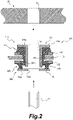
- Fig. 2 is a sectional view illustrating a state where the vibration-proof bush according to the embodiment of the present disclosure is being mounted on a vehicle body.
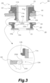
- Fig. 3 is a sectional view illustrating a state where the vibration-proof bush according to the embodiment of the present disclosure is being assembled.
- Fig. 1 is a view of an appearance of a center bearing support according to the embodiment of the present disclosure, illustrating a front view of the center bearing support and an enlarged view of a part of a bracket in the center bearing support.
- Fig. 2 is a sectional view illustrating a state where the vibration-proof bush according to the embodiment of the present disclosure is being mounted on a vehicle body.
- Fig. 3 is a sectional view illustrating a state where the vibration-proof bush according to
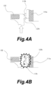
- Fig. 4 is a diagram for explaining the mechanism for of a fitting-completion sound according to the embodiment of the present disclosure.
- the vibration-proof bush has a substantially rotationally symmetrical shape, and in Figs. 2 to 4 , a section of various members by a plane including a center axis of the vibration-proof bush is schematically illustrated.
- FIG. 1 illustrates a mounting method of the center bearing support 10 according to this embodiment on the vehicle body side (a body of the vehicle)
- a circled part in Fig. 1 illustrates a part of a bracket 12 before a vibration-proof bush 100 is mounted in an enlarged manner.
- a long hole 12a is provided in the bracket 12. Configuring the hole formed in the bracket 12 as the long hole 12a allows dimensional errors of the various components in a front-and-rear direction of the vehicle body to be absorbed.
- the center bearing support 10 center-bearing support main body 11
- a propeller shaft not shown
- both ends of the propeller shaft are mounted on the vehicle body.
- the bracket 12 is mounted together with the vibration-proof bush 100 on a body 20 of the vehicle by a bolt.
- Fig. 2 illustrate a structure in which the vibration-proof bush 100 and the bracket 12 are mounted on the body 20 by tightening a shaft portion 30 (male screw) of the bolt to a female screw 21 provided on the body 20.
- a structure may be used in which the vibration-proof bush 100 and the bracket 12 are mounted on the body 20 by tightening a nut to the male screw provided on the body side (a structure in which the bolt is embedded in the body, for example).
- the vibration-proof bush 100 has an upper bush 110 mounted on the vehicle body side and a lower bush 120 configured to be fitted to the upper bush 110.
- the lower bush 120 is disposed on a side opposite to the upper bush 110 with respect to the bracket 12.
- the vibration-proof bush 100 according to this embodiment is provided with interference portions which interfere with each other in a process in which the lower bush 120 is fitted to the upper bush 110.
- the interference portions form a structure for generating a fitting-sound which is configured to generate a sound when the lower bush 120 is fitted to the upper bush 110 during temporary assembling. Details of the structure for generating the fitting-sound will be described later.
- the upper bush 110 has a first inner ring 111, a first outer ring 112 provided concentrically with the first inner ring 111, and a first elastic body 113 provided integrally with the first inner ring 111 and the first outer ring 112.
- the first inner ring 111 is an annular member constituted by metal or the like having a cylindrical portion 111a and an outward flange portion 111b provided on one end of the cylindrical portion 111a.
- the shaft portion 30 of the bolt is configured to be inserted inside the cylindrical portion 111a.
- the outward flange portion 111b is configured to abut against the body 20 of the vehicle.
- the first outer ring 112 is a flat-washer shaped member constituted by metal or the like.
- the first outer ring 112 allows the upper bush 110 to be stably supported by the bracket 12.
- the first elastic body 113 is constituted by an elastic body such as rubber.
- the first elastic body 113 includes an annular portion 113a exerting a vibration-proof function and an annular protrusion 113b provided on an outer peripheral surface of the annular portion 113a.
- the upper bush 110 integrally having the first inner ring 111, the first outer ring 112, and the first elastic body 113 can be obtained by performing insert molding by using the first inner ring 111 and the first outer ring 112 as insert components.
- the lower bush 120 has a second inner ring 121, a second outer ring 122 provided concentrically with the second inner ring 121, and a second elastic body 123 provided integrally with the second inner ring 121 and the second outer ring 122.
- the second inner ring 121 is a flat-washer shaped member constituted by metal or the like.
- the shaft portion 30 of the bolt is configured to be inserted inside the second inner ring 121 (inside an inner peripheral surface 121a).
- the second outer ring 122 is a flat-washer shaped member constituted by metal or the like.
- the second outer ring 122 allows the lower bush 120 to be stably supported by the bracket 12.
- the second elastic body 123 is constituted by an elastic body such as rubber.
- the second elastic body 123 includes an annular portion 123a exerting the vibration-proof function and a plurality of non-annular protrusions 123b provided on an inner peripheral surface of the annular portion 123a.
- the plurality of non-annular protrusions 123b are provided at intervals in a circumferential direction. In this embodiment, four non-annular protrusions 123b are disposed at equal intervals.
- the lower bush 120 integrally having the second inner ring 121, the second outer ring 122, and the second elastic body 123 can be obtained by performing insert molding by using the second inner ring 121 and the second outer ring 122 as insert components.
- the vibration-proof bush 100 is configured such that the fitting is performed between the outer peripheral surface of the first elastic body 113 in the upper bush 110 and the inner peripheral surface of the second elastic body 123 in the lower bush 120.
- the annular protrusion 113b is provided on the outer peripheral surface of the first elastic body 113
- the plurality of non-annular protrusions 123b are provided on the inner peripheral surface of the second elastic body 123.
- the annular protrusion 113b provided on the first elastic body 113 and the plurality of non-annular protrusions 123b provided on the second elastic body 123 function as the interference portions which interfere with each other in the process in which the lower bush 120 is fitted to the upper bush 110.
- annular protrusion 113b and the non-annular protrusion 123b are deformed by pressing each other in the process of fitting when the lower bush 120 is temporarily assembled with the upper bush 110.
- Fig. 4(a) the annular protrusion 113b and the non-annular protrusion 123b deformed by pressing each other are indicated by solid lines, while a state before the deformation is indicated by dotted lines.
- the annular protrusion 113b and the non-annular protrusion 123b both return to original shapes.
- the annular protrusion 113b and the non-annular protrusion 123b are configured to generate a sound when they rapidly return to the original states as they are flipped by elastic restoring forces (see Fig. 4B ).
- the interference portions constituted by the protrusions (the annular protrusion 113b and the plurality of non-annular protrusions 123b) provided on both the upper bush 110 and the lower bush 120, respectively, form the fitting-sound generation structure in which a sound is generated when the lower bush 120 is fitted to the upper bush 110.
- the annular protrusion 113b and the plurality of non-annular protrusions 123b dimensional shapes, rigidity (materials of the first elastic body 113 and the second elastic body 123) and the number of the non-annular protrusions 123b and the like may be set as appropriate so that the sound is generated when the lower bush 120 is fitted to the upper bush 110 during temporary assembling.
- the non-annular protrusion 123b in the lower bush 120 includes a first inclined surface 123b1 and a second inclined surface 123b2 provided closer to the upper bush 110 than the first inclined surface 123b1.
- the first inclined surface 123b1 is configured to go away from the center axis of the lower bush 120 as it goes away from the upper bush 110.
- the second inclined surface 123b2 is configured to go away from the center axis of the lower bush 120 as it goes closer to the upper bush 110.
- An inclination angle ⁇ of the first inclined surface 123b1 with respect to a plane perpendicular to the center axis of the lower bush 120 is larger than an inclination angle ⁇ of the second inclined surface 123b2 with respect to the plane perpendicular to the center axis (see Fig. 3 ).
- the interference portion forms the fitting-sound generation structure
- the vibration-proof bush 100 since the interference portion forms the fitting-sound generation structure, when the lower bush 120 is fitted to the upper bush 110 during the temporary assembling, a sound is generated. This allows an operator to easily confirm that they are fitted. This suppresses incomplete fitting of the upper bush 110 and the lower bush 120.
- removal of the vibration-proof bush 100 from the bracket 12 of the center bearing support 10 can be suppressed. Therefore, operation performance can be improved.
- the protrusion provided on the lower bush 120 for generating the fitting sound has a plurality of the non-annular protrusions 123b provided at intervals in the circumferential direction.
- a clearance is formed between the adjacent non-annular protrusions 123b, and the sound generated when the fitting is completed can be effectively propagated to the outside. Therefore, the operator can more reliably confirm that the upper bush 110 and the lower bush 120 are fitted to each other.
- the following advantages can be obtained. That is, in the process in which the lower bush 120 is fitted to the upper bush 110, a large resisting force is generated when the non-annular protrusion 123b overrides the annular protrusion 113b and thus, at the moment of fitting, they can return to the original shapes like being strongly flipped. This generates a large sound. Furthermore, when a manufacturing method of insert molding of the lower bush 120 using a die (not shown) which opens in a vertical direction in Fig. 3 is employed, for example, the plurality of non-annular protrusions 123b are undercut.
- the above-described embodiment illustrates the structure in which the annular protrusion 113b is provided on the upper bush 110, and the plurality of non-annular protrusions 123b are provided on the lower bush 120 at intervals in the circumferential direction.
- a plurality of non-annular protrusions may be provided on the upper bush at intervals in the circumferential direction, and an annular protrusion may be provided on the lower bush.
Landscapes
- Engineering & Computer Science (AREA)
- General Engineering & Computer Science (AREA)
- Mechanical Engineering (AREA)
- Physics & Mathematics (AREA)
- Acoustics & Sound (AREA)
- Aviation & Aerospace Engineering (AREA)
- Transportation (AREA)
- Chemical & Material Sciences (AREA)
- Combustion & Propulsion (AREA)
- Manufacturing & Machinery (AREA)
- Vibration Prevention Devices (AREA)
- Springs (AREA)
- Support Of The Bearing (AREA)
- Motor Power Transmission Devices (AREA)
Abstract
Description
- The present disclosure relates to a vibration-proof bush provided in a center bearing support.
- A propeller shaft provided in a vehicle body includes a center bearing support which supports a center bearing thereof. This suppresses transmission of vibration generated in the propeller shaft to a vehicle body (body of a vehicle) side and reduces a noise such as muffled sound in a cabin. Moreover, in the center bearing support, in order to improve an effect to suppress the transmission of vibration from the propeller shaft, a technology of providing a vibration-proof bush on a bracket mounted on a vehicle body side is also known. In the technology as above, the center bearing support is mounted on the vehicle body by fixing the bracket together with the vibration-proof bush to the vehicle body by a bolt. Here, by forming a hole formed in the bracket (hole through which a shaft of the bolt is inserted) into a long hole, dimensional errors of various components in a front-and-rear direction of the vehicle body are absorbed. In this structure, when the various components are to be mounted on the vehicle body, first, the center bearing support is mounted on the propeller shaft and then, both ends of the propeller shaft are mounted on the vehicle body. Then, lastly, while position adjustment is being conducted so that the dimensional errors are absorbed, the bracket is mounted together with the vibrations-proof bush on the vehicle body by the bolt.
- Here, the vibration-proof bush includes an upper bush mounted on the vehicle body side and a lower bush provided on a side opposite to the upper bush with respect to the bracket. In order to mount the bracket on the vehicle body together with the vibration-proof bush at a last stage, such methods have been conventionally employed that, the upper bush is temporarily fixed to the vehicle body side and then, in a state where the lower bush is disposed on the bracket, by means of screwing by the bolt, the bracket is fixed to the vehicle body and, at the same time, the vibration-proof bush is assembled. However, depending on dimensions of the various components and the like, such methods cannot be employed in some cases. Thus, such method has been considered that an upper bush and a lower bush that are fitted to each other are temporarily fixed to the bracket in advance as a vibration-proof bush. However, in this method, if the fitting between the upper bush and the lower bush is not complete, there is a concern that the vibration-proof bush is removed from the bracket during operation, which lowers operation performance.
-
- [PTL 1]
Japanese Patent Application Publication No. 2008-132803 - [PTL 2]
Japanese Patent Application Publication No. 2011-131822 - [PTL 3]
Japanese Patent Application Publication No. 2019-19934 - An object of the present disclosure is to provide a vibration-proof bush capable of suppressing removal caused by incomplete fitting when an upper bush and a lower bush are temporarily assembled.
- The present disclosure employs the following means in order to achieve the above object.
- The present disclosure is related to a vibration-proof bush provided in a center bearing support which supports a center bearing of a propeller shaft, including:
- an upper bush configured to be mounted on a vehicle body side; and
- a lower bush configured to be fitted to the upper bush, wherein
- the vibration-proof bush includes interference portions configured to interfere with each other in a process of fitting the lower bush to the upper bush, and the interference portions form a fitting-sound generation structure in which a sound is generated when the lower bush is fitted to the upper bush during temporary assembling.
- According to the present disclosure, since the interference portions form the fitting-sound generation structure, when the lower bush is fitted to the upper bush during the temporary assembling, a sound is generated. As a result, an operator can easily confirm that they are fitted to each other. Therefore, incomplete fitting of the upper bush and the lower bush can be suppressed.
- The interference portions may have protrusions provided on both the upper bush and the lower bush, respectively, so that the protrusions are deformed by pressing each other in the process of fitting the lower bush to the upper bush during the temporary assembling, and the sound is generated by the protrusions returning to their original shapes when the fitting is completed.
- Among the protrusions constituting the interference portion, the protrusion provided on either one of the upper bush and the lower bush may have an annular protrusion, and the protrusion provided on the other may have non-annular protrusions provided in plural at intervals in a circumferential direction.
- When the protrusion provided on the other of the upper bush and the lower bush has the non-annular protrusions provided in plural at the intervals in the circumferential direction, a clearance formed between the adjacent non-annular protrusions allows effective propagation of the sound to an outside.
- The upper bush may have a first inner ring, a first outer ring provided concentrically with the first inner ring, and a first elastic body provided integrally with the first inner ring and the first outer ring,
- the lower bush may have a second inner ring, a second outer ring provided concentrically with the second inner ring, and a second elastic body provided integrally with the second inner ring and the second outer ring; and
- an outer peripheral surface of the first elastic body and an inner peripheral surface of the second elastic body may be configured to be fitted to each other, and the annular protrusion may be provided on the outer peripheral surface of the first elastic body, and a plurality of the non-annular protrusions may be provided on the inner peripheral surface of the second elastic body.
- The non-annular protrusion may include a first inclined surface in which a distance from a center axis of the lower bush increases as a distance from the upper bush increases, and a second inclined surface in which a distance from the center axis increases as a distance from the upper bush decreases, the second inclined surface being provided closer to the upper bush than the first inclined surface; and
an inclination angle of the first inclined surface with respect to a plane perpendicular to the center axis may be larger than an inclination angle of the second inclined surface with respect to the plane perpendicular to the center axis. - As described above, according to the present disclosure, removal caused by incomplete fitting when the upper bush and the lower bush are temporarily assembled can be suppressed.
-
- [
Fig. 1 ]
Fig. 1 is a view of an appearance of a center bearing support according to an embodiment of the present disclosure. - [
Fig. 2 ]
Fig. 2 is a sectional view illustrating a state where a vibration-proof bush according to the embodiment of the present disclosure is being mounted on a vehicle body. - [
Fig. 3 ]
Fig. 3 is a sectional view illustrating a state where the vibration-proof bush according to the embodiment of the present disclosure is being assembled. - [
Fig. 4 ]
Fig. 4 is a diagram for explaining a mechanism for generation of a fitting-completion sound according to the embodiment of the present disclosure. - Hereinafter, by referring to the drawings, an aspect for embodying the present disclosure will be described in detail exemplarily on the basis of an embodiment. However, dimensions, materials, shapes, relative dispositions, and the like of constituent components thereof described in this embodiment are not intended to limit a range of the present disclosure only to them unless otherwise particularly described specifically.
- By referring to
Figs. 1 to 4 , a vibration-proof bush according to the embodiment of the present disclosure will be described.Fig. 1 is a view of an appearance of a center bearing support according to the embodiment of the present disclosure, illustrating a front view of the center bearing support and an enlarged view of a part of a bracket in the center bearing support.Fig. 2 is a sectional view illustrating a state where the vibration-proof bush according to the embodiment of the present disclosure is being mounted on a vehicle body.Fig. 3 is a sectional view illustrating a state where the vibration-proof bush according to the embodiment of the present disclosure is being assembled. InFig. 3 , together with the sectional view of the entire vibration-proof bush, an enlarged sectional view of a part, which is circled, of the vibration-proof bush is illustrated.Fig. 4 is a diagram for explaining the mechanism for of a fitting-completion sound according to the embodiment of the present disclosure. The vibration-proof bush has a substantially rotationally symmetrical shape, and inFigs. 2 to 4 , a section of various members by a plane including a center axis of the vibration-proof bush is schematically illustrated. - By referring to
Figs. 1 and2 , a mounting method of thecenter bearing support 10 according to this embodiment on the vehicle body side (a body of the vehicle) will be described. A circled part inFig. 1 illustrates a part of abracket 12 before a vibration-proof bush 100 is mounted in an enlarged manner. As illustrated in this figure, along hole 12a is provided in thebracket 12. Configuring the hole formed in thebracket 12 as thelong hole 12a allows dimensional errors of the various components in a front-and-rear direction of the vehicle body to be absorbed. That is, when the various components are being mounted on the vehicle body, the center bearing support 10 (center-bearing support main body 11) is mounted on a propeller shaft (not shown), and then, both ends of the propeller shaft are mounted on the vehicle body. Then, lastly, while positional adjustment is conducted so as to absorb the dimensional errors, thebracket 12 is mounted together with the vibration-proof bush 100 on abody 20 of the vehicle by a bolt. Note thatFig. 2 illustrate a structure in which the vibration-proof bush 100 and thebracket 12 are mounted on thebody 20 by tightening a shaft portion 30 (male screw) of the bolt to afemale screw 21 provided on thebody 20. However, another structure may be used in which the vibration-proof bush 100 and thebracket 12 are mounted on thebody 20 by tightening a nut to the male screw provided on the body side (a structure in which the bolt is embedded in the body, for example). - By referring to
Figs. 2 and3 , the configuration of the vibration-proof bush 100 according to this embodiment will be described. The vibration-proof bush 100 according to this embodiment has anupper bush 110 mounted on the vehicle body side and alower bush 120 configured to be fitted to theupper bush 110. Thelower bush 120 is disposed on a side opposite to theupper bush 110 with respect to thebracket 12. The vibration-proof bush 100 according to this embodiment is provided with interference portions which interfere with each other in a process in which thelower bush 120 is fitted to theupper bush 110. The interference portions form a structure for generating a fitting-sound which is configured to generate a sound when thelower bush 120 is fitted to theupper bush 110 during temporary assembling. Details of the structure for generating the fitting-sound will be described later. - The
upper bush 110 has a firstinner ring 111, a firstouter ring 112 provided concentrically with the firstinner ring 111, and a firstelastic body 113 provided integrally with the firstinner ring 111 and the firstouter ring 112. The firstinner ring 111 is an annular member constituted by metal or the like having acylindrical portion 111a and anoutward flange portion 111b provided on one end of thecylindrical portion 111a. Theshaft portion 30 of the bolt is configured to be inserted inside thecylindrical portion 111a. Theoutward flange portion 111b is configured to abut against thebody 20 of the vehicle. The firstouter ring 112 is a flat-washer shaped member constituted by metal or the like. The firstouter ring 112 allows theupper bush 110 to be stably supported by thebracket 12. The firstelastic body 113 is constituted by an elastic body such as rubber. The firstelastic body 113 includes anannular portion 113a exerting a vibration-proof function and anannular protrusion 113b provided on an outer peripheral surface of theannular portion 113a. Theupper bush 110 integrally having the firstinner ring 111, the firstouter ring 112, and the firstelastic body 113 can be obtained by performing insert molding by using the firstinner ring 111 and the firstouter ring 112 as insert components. - The
lower bush 120 has a secondinner ring 121, a secondouter ring 122 provided concentrically with the secondinner ring 121, and a secondelastic body 123 provided integrally with the secondinner ring 121 and the secondouter ring 122. The secondinner ring 121 is a flat-washer shaped member constituted by metal or the like. Theshaft portion 30 of the bolt is configured to be inserted inside the second inner ring 121 (inside an innerperipheral surface 121a). The secondouter ring 122 is a flat-washer shaped member constituted by metal or the like. The secondouter ring 122 allows thelower bush 120 to be stably supported by thebracket 12. The secondelastic body 123 is constituted by an elastic body such as rubber. The secondelastic body 123 includes anannular portion 123a exerting the vibration-proof function and a plurality ofnon-annular protrusions 123b provided on an inner peripheral surface of theannular portion 123a. The plurality ofnon-annular protrusions 123b are provided at intervals in a circumferential direction. In this embodiment, fournon-annular protrusions 123b are disposed at equal intervals. Thelower bush 120 integrally having the secondinner ring 121, the secondouter ring 122, and the secondelastic body 123 can be obtained by performing insert molding by using the secondinner ring 121 and the secondouter ring 122 as insert components. - The vibration-
proof bush 100 according to the embodiment is configured such that the fitting is performed between the outer peripheral surface of the firstelastic body 113 in theupper bush 110 and the inner peripheral surface of the secondelastic body 123 in thelower bush 120. As described above, theannular protrusion 113b is provided on the outer peripheral surface of the firstelastic body 113, and the plurality ofnon-annular protrusions 123b are provided on the inner peripheral surface of the secondelastic body 123. Theannular protrusion 113b provided on the firstelastic body 113 and the plurality ofnon-annular protrusions 123b provided on the secondelastic body 123 function as the interference portions which interfere with each other in the process in which thelower bush 120 is fitted to theupper bush 110. - This point will be described in detail by referring to
Fig. 4 . The above-describedannular protrusion 113b and thenon-annular protrusion 123b are deformed by pressing each other in the process of fitting when thelower bush 120 is temporarily assembled with theupper bush 110. inFig. 4(a) , theannular protrusion 113b and thenon-annular protrusion 123b deformed by pressing each other are indicated by solid lines, while a state before the deformation is indicated by dotted lines. At a moment when theupper bush 110 and thelower bush 120 are fitted to each other (a moment when thenon-annular protrusion 123b overrides theannular protrusion 113b), theannular protrusion 113b and thenon-annular protrusion 123b both return to original shapes. Theannular protrusion 113b and thenon-annular protrusion 123b are configured to generate a sound when they rapidly return to the original states as they are flipped by elastic restoring forces (seeFig. 4B ). - As described above, the interference portions constituted by the protrusions (the
annular protrusion 113b and the plurality ofnon-annular protrusions 123b) provided on both theupper bush 110 and thelower bush 120, respectively, form the fitting-sound generation structure in which a sound is generated when thelower bush 120 is fitted to theupper bush 110. In regard to theannular protrusion 113b and the plurality ofnon-annular protrusions 123b, dimensional shapes, rigidity (materials of the firstelastic body 113 and the second elastic body 123) and the number of thenon-annular protrusions 123b and the like may be set as appropriate so that the sound is generated when thelower bush 120 is fitted to theupper bush 110 during temporary assembling. - The
non-annular protrusion 123b in thelower bush 120 according to the embodiment includes a first inclined surface 123b1 and a second inclined surface 123b2 provided closer to theupper bush 110 than the first inclined surface 123b1. The first inclined surface 123b1 is configured to go away from the center axis of thelower bush 120 as it goes away from theupper bush 110. The second inclined surface 123b2 is configured to go away from the center axis of thelower bush 120 as it goes closer to theupper bush 110. An inclination angle α of the first inclined surface 123b1 with respect to a plane perpendicular to the center axis of thelower bush 120 is larger than an inclination angle β of the second inclined surface 123b2 with respect to the plane perpendicular to the center axis (seeFig. 3 ). - According to the vibration-
proof bush 100 according to the embodiment, since the interference portion forms the fitting-sound generation structure, when thelower bush 120 is fitted to theupper bush 110 during the temporary assembling, a sound is generated. This allows an operator to easily confirm that they are fitted. This suppresses incomplete fitting of theupper bush 110 and thelower bush 120. As a result, during an operation of mounting thecenter bearing support 10 on the vehicle body or the like, removal of the vibration-proof bush 100 from thebracket 12 of thecenter bearing support 10 can be suppressed. Therefore, operation performance can be improved. - The protrusion provided on the
lower bush 120 for generating the fitting sound has a plurality of thenon-annular protrusions 123b provided at intervals in the circumferential direction. Thus, a clearance is formed between the adjacentnon-annular protrusions 123b, and the sound generated when the fitting is completed can be effectively propagated to the outside. Therefore, the operator can more reliably confirm that theupper bush 110 and thelower bush 120 are fitted to each other. - Since the inclination angle α of the first inclined surface 123b1 is larger than the inclination angle β of the second inclined surface 123b2, the following advantages can be obtained. That is, in the process in which the
lower bush 120 is fitted to theupper bush 110, a large resisting force is generated when thenon-annular protrusion 123b overrides theannular protrusion 113b and thus, at the moment of fitting, they can return to the original shapes like being strongly flipped. This generates a large sound. Furthermore, when a manufacturing method of insert molding of thelower bush 120 using a die (not shown) which opens in a vertical direction inFig. 3 is employed, for example, the plurality ofnon-annular protrusions 123b are undercut. Thus, when a molding product is being taken out of the die, so-called forced extraction needs to be performed. However, the relationship between the inclination angle α and the inclination angle β as above allows the forced extraction to be performed without affecting thenon-annular protrusions 123b. - The above-described embodiment illustrates the structure in which the
annular protrusion 113b is provided on theupper bush 110, and the plurality ofnon-annular protrusions 123b are provided on thelower bush 120 at intervals in the circumferential direction. However, in the present disclosure, a plurality of non-annular protrusions may be provided on the upper bush at intervals in the circumferential direction, and an annular protrusion may be provided on the lower bush. This structure can achieves the same effect as that in the above-described embodiment. -
- 10
- Center bearing support
- 11
- Center-bearing support main body
- 12
- Bracket
- 12a
- Long hole
- 20
- Body
- 21
- Female screw
- 30
- Shaft portion
- 100
- Vibration-proof bush
- 110
- Upper bush
- 111
- Inner ring
- 111a
- Cylindrical portion
- 111b
- Outward flange portion
- 112
- First outer ring
- 113
- First elastic body
- 113a
- Annular portion
- 113b
- Annular protrusion
- 120
- Lower bush
- 121
- Second inner ring
- 121a
- Inner peripheral surface
- 122
- Second outer ring
- 123a
- Annular portion
- 123b
- Non-annular protrusion
Claims (5)
- A vibration-proof bush provided in a center bearing support which supports a center bearing of a propeller shaft, comprising:an upper bush configured to be mounted on a vehicle body side; anda lower bush configured to be fitted to the upper bush, whereinthe vibration-proof bush includes interference portions configured to interfere with each other in a process of fitting the lower bush to the upper bush, and the interference portions form a fitting-sound generation structure in which a sound is generated when the lower bush is fitted to the upper bush during temporary assembling.
- The vibration-proof bush according to claim 1, wherein
the interference portions have protrusions provided on both the upper bush and the lower bush, respectively, so that the protrusions are deformed by pressing each other in the process of fitting the lower bush to the upper bush during the temporary assembling, and the sound is generated by the protrusions returning to their original shapes when the fitting is completed. - The vibration-proof bush according to claim 2, wherein
among the protrusions constituting the interference portion, the protrusion provided on either one of the upper bush and the lower bush has an annular protrusion, and the protrusions provided on the other has non-annular protrusions provided in plural at intervals in a circumferential direction. - The vibration-proof bush according to claim 3, whereinthe upper bush has a first inner ring, a first outer ring provided concentrically with the first inner ring, and a first elastic body provided integrally with the first inner ring and the first outer ring,the lower bush has a second inner ring, a second outer ring provided concentrically with the second inner ring, and a second elastic body provided integrally with the second inner ring and the second outer ring; andan outer peripheral surface of the first elastic body and an inner peripheral surface of the second elastic body are configured to be fitted to each other, and the annular protrusion is provided on the outer peripheral surface of the first elastic body, and a plurality of the non-annular protrusions are provided on the inner peripheral surface of the second elastic body.
- The vibration-proof bush according to claim 4, whereinthe non-annular protrusion includes a first inclined surface in which a distance from a center axis of the lower bush increases as a distance from the upper bush increases, and a second inclined surface in which a distance from the center axis increases as a distance from the upper bush decreases, the second inclined surface being provided closer to the upper bush than the first inclined surface; andan inclination angle of the first inclined surface with respect to a plane perpendicular to the center axis is larger than an inclination angle of the second inclination surface with respect to the plane perpendicular to the center axis.
Applications Claiming Priority (2)
| Application Number | Priority Date | Filing Date | Title |
|---|---|---|---|
| JP2020066872 | 2020-04-02 | ||
| PCT/JP2021/010838 WO2021200160A1 (en) | 2020-04-02 | 2021-03-17 | Vibration-proof bush |
Publications (2)
| Publication Number | Publication Date |
|---|---|
| EP4130508A1 true EP4130508A1 (en) | 2023-02-08 |
| EP4130508A4 EP4130508A4 (en) | 2024-04-10 |
Family
ID=77929285
Family Applications (1)
| Application Number | Title | Priority Date | Filing Date |
|---|---|---|---|
| EP21780802.1A Pending EP4130508A4 (en) | 2020-04-02 | 2021-03-17 | VIBRATION DAMPING BUSHING |
Country Status (5)
| Country | Link |
|---|---|
| US (1) | US12168395B2 (en) |
| EP (1) | EP4130508A4 (en) |
| JP (1) | JP7286009B2 (en) |
| CN (1) | CN114981558B (en) |
| WO (1) | WO2021200160A1 (en) |
Families Citing this family (3)
| Publication number | Priority date | Publication date | Assignee | Title |
|---|---|---|---|---|
| JP7594885B2 (en) | 2020-11-11 | 2024-12-05 | 倉敷化工株式会社 | Center bearing support device |
| JP7582233B2 (en) * | 2022-03-09 | 2024-11-13 | 株式会社デンソー | Damper and Electrical Equipment |
| JP2025004887A (en) * | 2023-06-27 | 2025-01-16 | 住友電装株式会社 | Electrical Junction Box |
Family Cites Families (25)
| Publication number | Priority date | Publication date | Assignee | Title |
|---|---|---|---|---|
| US3016562A (en) * | 1958-09-08 | 1962-01-16 | William P Reid | Grommet |
| US4033535A (en) * | 1973-05-18 | 1977-07-05 | Eaton Corporation | Strain-relief bushing |
| US5069586A (en) * | 1990-08-27 | 1991-12-03 | Casey Marion B | Self-locking two-part grommet |
| JP2965766B2 (en) * | 1991-06-18 | 1999-10-18 | 花王株式会社 | Method for producing sulfobetaine |
| JPH0558988U (en) | 1992-01-21 | 1993-08-03 | エヌ・オー・ケー・メグラスティック株式会社 | mount |
| CN2302128Y (en) * | 1997-10-05 | 1998-12-30 | 叶程 | Fountain pen |
| JP2000225944A (en) * | 1999-02-03 | 2000-08-15 | Toyo Tire & Rubber Co Ltd | Anti-vibration rubber bush for railroad vehicle axle beam device |
| JP4617619B2 (en) | 2001-07-26 | 2011-01-26 | 三菱自動車工業株式会社 | Shock absorber assembly structure |
| JP2003094969A (en) | 2001-09-27 | 2003-04-03 | Showa Corp | Bracket mounting structure for propeller shaft |
| JP4737898B2 (en) | 2001-09-27 | 2011-08-03 | 株式会社ショーワ | Propeller shaft bracket mounting structure |
| JP2004306630A (en) * | 2003-04-02 | 2004-11-04 | Suzuki Motor Corp | Trailing arm support structure |
| DE102004051566B4 (en) * | 2004-10-22 | 2008-06-12 | SGF SüDDEUTSCHE GELENKSCHEIBENFABRIK GMBH & CO. KG | Resilient socket arrangement |
| JP2007237949A (en) | 2006-03-09 | 2007-09-20 | Nok Corp | Center bearing support mounting structure |
| JP4840103B2 (en) | 2006-11-27 | 2011-12-21 | マツダ株式会社 | Propeller shaft support device and assembly method thereof |
| JP2011131822A (en) | 2009-12-25 | 2011-07-07 | Showa Corp | Supporting structure for propeller shaft |
| JP5780638B2 (en) * | 2011-06-21 | 2015-09-16 | 住友理工株式会社 | Anti-vibration bush and manufacturing method thereof |
| JP6008090B2 (en) * | 2012-04-26 | 2016-10-19 | Nok株式会社 | Center bearing support |
| KR101193248B1 (en) * | 2012-06-18 | 2012-10-18 | 동양기전 주식회사 | Bolt assembly for wiper apparatus of a vehicle |
| JP5619947B2 (en) * | 2013-03-28 | 2014-11-05 | 株式会社ブリヂストン | Torque rod |
| WO2014199418A1 (en) * | 2013-06-13 | 2014-12-18 | 住友理工株式会社 | Vibration damping device |
| JP6190638B2 (en) * | 2013-06-27 | 2017-08-30 | 住友理工株式会社 | Anti-vibration bush and method for manufacturing anti-vibration bush |
| JP5929962B2 (en) * | 2014-05-16 | 2016-06-08 | トヨタ自動車株式会社 | Mounting structure of biasing member |
| CN206106872U (en) * | 2016-09-14 | 2017-04-19 | 上汽通用五菱汽车股份有限公司 | Stabilizer bar connecting rod assembly |
| JP6934345B2 (en) | 2017-07-20 | 2021-09-15 | Nok株式会社 | Anti-vibration mount and its assembly method |
| EP3976988B1 (en) * | 2019-06-03 | 2023-08-09 | BASF Polyurethanes GmbH | Spring element, in particular jounce bumper, for a vehicle suspension |
-
2021
- 2021-03-17 WO PCT/JP2021/010838 patent/WO2021200160A1/en not_active Ceased
- 2021-03-17 EP EP21780802.1A patent/EP4130508A4/en active Pending
- 2021-03-17 US US17/790,185 patent/US12168395B2/en active Active
- 2021-03-17 CN CN202180009276.4A patent/CN114981558B/en active Active
- 2021-03-17 JP JP2022511846A patent/JP7286009B2/en active Active
Also Published As
| Publication number | Publication date |
|---|---|
| JP7286009B2 (en) | 2023-06-02 |
| US20230049995A1 (en) | 2023-02-16 |
| EP4130508A4 (en) | 2024-04-10 |
| CN114981558B (en) | 2026-02-03 |
| JPWO2021200160A1 (en) | 2021-10-07 |
| WO2021200160A1 (en) | 2021-10-07 |
| CN114981558A (en) | 2022-08-30 |
| US12168395B2 (en) | 2024-12-17 |
Similar Documents
| Publication | Publication Date | Title |
|---|---|---|
| EP4130508A1 (en) | Vibration-proof bush | |
| EP2532918B1 (en) | Vibration-damping device | |
| JP6532367B2 (en) | Tubular vibration control with bracket | |
| CN109690126B (en) | Vibration-proof device | |
| WO2013140700A1 (en) | Vibration damper | |
| EP3358209B1 (en) | Bush bearing and bearing mechanism provided therewith | |
| CN109398057B (en) | vehicle | |
| JP2008185193A (en) | Vibration isolator | |
| WO2021020065A1 (en) | Center bearing support structure | |
| JP2008240884A (en) | Vibration control supporting member and automobile component unit supporting device | |
| JP7079784B2 (en) | Cylindrical motor mount for electric vehicles | |
| JP4286078B2 (en) | Steering gear housing fixing structure | |
| JP2023135328A (en) | Cylindrical anti-vibration device | |
| JP7174659B2 (en) | Bracket for cylindrical anti-vibration device | |
| EP1188586B1 (en) | Mount insulator | |
| JP6584287B2 (en) | Transmission case reinforcement structure | |
| JP7680918B2 (en) | Multiple types of cylindrical vibration isolators with brackets and their manufacturing methods | |
| CN224161578U (en) | A locking assembly and a vehicle | |
| JP4410544B2 (en) | Flange member for piping installation | |
| JP2020020439A (en) | Anti-vibration grommet | |
| JP2006311657A (en) | Electric actuator | |
| JP2025129821A (en) | Vehicle wheel structure | |
| JP4449634B2 (en) | Wheel structure | |
| WO2025069619A1 (en) | Method for manufacturing vibration isolation device | |
| JP2026040709A (en) | Cylindrical vibration isolation device |
Legal Events
| Date | Code | Title | Description |
|---|---|---|---|
| STAA | Information on the status of an ep patent application or granted ep patent |
Free format text: STATUS: THE INTERNATIONAL PUBLICATION HAS BEEN MADE |
|
| PUAI | Public reference made under article 153(3) epc to a published international application that has entered the european phase |
Free format text: ORIGINAL CODE: 0009012 |
|
| STAA | Information on the status of an ep patent application or granted ep patent |
Free format text: STATUS: REQUEST FOR EXAMINATION WAS MADE |
|
| 17P | Request for examination filed |
Effective date: 20220617 |
|
| AK | Designated contracting states |
Kind code of ref document: A1 Designated state(s): AL AT BE BG CH CY CZ DE DK EE ES FI FR GB GR HR HU IE IS IT LI LT LU LV MC MK MT NL NO PL PT RO RS SE SI SK SM TR |
|
| DAV | Request for validation of the european patent (deleted) | ||
| DAX | Request for extension of the european patent (deleted) | ||
| A4 | Supplementary search report drawn up and despatched |
Effective date: 20240307 |
|
| RIC1 | Information provided on ipc code assigned before grant |
Ipc: F16F 1/38 20060101ALI20240301BHEP Ipc: B60K 17/24 20060101ALI20240301BHEP Ipc: F16F 15/08 20060101ALI20240301BHEP Ipc: F16F 1/36 20060101AFI20240301BHEP |
|
| RIN1 | Information on inventor provided before grant (corrected) |
Inventor name: RYU, YOSHIHISA |
|
| STAA | Information on the status of an ep patent application or granted ep patent |
Free format text: STATUS: EXAMINATION IS IN PROGRESS |
|
| 17Q | First examination report despatched |
Effective date: 20250512 |