EP4130435A1 - Guide vane ring for a turbomachine, turbomachine and method for assembling a guide vane ring - Google Patents
Guide vane ring for a turbomachine, turbomachine and method for assembling a guide vane ring Download PDFInfo
- Publication number
- EP4130435A1 EP4130435A1 EP22188200.4A EP22188200A EP4130435A1 EP 4130435 A1 EP4130435 A1 EP 4130435A1 EP 22188200 A EP22188200 A EP 22188200A EP 4130435 A1 EP4130435 A1 EP 4130435A1
- Authority
- EP
- European Patent Office
- Prior art keywords
- guide
- bearing
- inner ring
- journal
- vane
- Prior art date
- Legal status (The legal status is an assumption and is not a legal conclusion. Google has not performed a legal analysis and makes no representation as to the accuracy of the status listed.)
- Withdrawn
Links
- 238000000034 method Methods 0.000 title claims description 14
- 238000007789 sealing Methods 0.000 claims description 15
- OKTJSMMVPCPJKN-UHFFFAOYSA-N Carbon Chemical compound [C] OKTJSMMVPCPJKN-UHFFFAOYSA-N 0.000 claims description 4
- 229910052799 carbon Inorganic materials 0.000 claims description 3
- 239000002184 metal Substances 0.000 claims description 3
- 238000011161 development Methods 0.000 description 11
- 230000018109 developmental process Effects 0.000 description 11
- 230000008901 benefit Effects 0.000 description 6
- 230000008859 change Effects 0.000 description 4
- 230000007423 decrease Effects 0.000 description 4
- 239000012530 fluid Substances 0.000 description 2
- 230000009467 reduction Effects 0.000 description 2
- 229910001339 C alloy Inorganic materials 0.000 description 1
- 238000006243 chemical reaction Methods 0.000 description 1
- 230000000295 complement effect Effects 0.000 description 1
- 238000013016 damping Methods 0.000 description 1
- 230000001419 dependent effect Effects 0.000 description 1
- 238000005553 drilling Methods 0.000 description 1
- 229910001092 metal group alloy Inorganic materials 0.000 description 1
- 230000006641 stabilisation Effects 0.000 description 1
- 238000011105 stabilization Methods 0.000 description 1
- 239000002966 varnish Substances 0.000 description 1
Images


Classifications
-
- F—MECHANICAL ENGINEERING; LIGHTING; HEATING; WEAPONS; BLASTING
- F01—MACHINES OR ENGINES IN GENERAL; ENGINE PLANTS IN GENERAL; STEAM ENGINES
- F01D—NON-POSITIVE DISPLACEMENT MACHINES OR ENGINES, e.g. STEAM TURBINES
- F01D9/00—Stators
- F01D9/02—Nozzles; Nozzle boxes; Stator blades; Guide conduits, e.g. individual nozzles
- F01D9/04—Nozzles; Nozzle boxes; Stator blades; Guide conduits, e.g. individual nozzles forming ring or sector
- F01D9/042—Nozzles; Nozzle boxes; Stator blades; Guide conduits, e.g. individual nozzles forming ring or sector fixing blades to stators
-
- F—MECHANICAL ENGINEERING; LIGHTING; HEATING; WEAPONS; BLASTING
- F01—MACHINES OR ENGINES IN GENERAL; ENGINE PLANTS IN GENERAL; STEAM ENGINES
- F01D—NON-POSITIVE DISPLACEMENT MACHINES OR ENGINES, e.g. STEAM TURBINES
- F01D9/00—Stators
- F01D9/02—Nozzles; Nozzle boxes; Stator blades; Guide conduits, e.g. individual nozzles
- F01D9/04—Nozzles; Nozzle boxes; Stator blades; Guide conduits, e.g. individual nozzles forming ring or sector
- F01D9/041—Nozzles; Nozzle boxes; Stator blades; Guide conduits, e.g. individual nozzles forming ring or sector using blades
-
- F—MECHANICAL ENGINEERING; LIGHTING; HEATING; WEAPONS; BLASTING
- F01—MACHINES OR ENGINES IN GENERAL; ENGINE PLANTS IN GENERAL; STEAM ENGINES
- F01D—NON-POSITIVE DISPLACEMENT MACHINES OR ENGINES, e.g. STEAM TURBINES
- F01D11/00—Preventing or minimising internal leakage of working-fluid, e.g. between stages
- F01D11/003—Preventing or minimising internal leakage of working-fluid, e.g. between stages by packing rings; Mechanical seals
-
- F—MECHANICAL ENGINEERING; LIGHTING; HEATING; WEAPONS; BLASTING
- F01—MACHINES OR ENGINES IN GENERAL; ENGINE PLANTS IN GENERAL; STEAM ENGINES
- F01D—NON-POSITIVE DISPLACEMENT MACHINES OR ENGINES, e.g. STEAM TURBINES
- F01D17/00—Regulating or controlling by varying flow
- F01D17/10—Final actuators
- F01D17/12—Final actuators arranged in stator parts
- F01D17/14—Final actuators arranged in stator parts varying effective cross-sectional area of nozzles or guide conduits
- F01D17/16—Final actuators arranged in stator parts varying effective cross-sectional area of nozzles or guide conduits by means of nozzle vanes
- F01D17/162—Final actuators arranged in stator parts varying effective cross-sectional area of nozzles or guide conduits by means of nozzle vanes for axial flow, i.e. the vanes turning around axes which are essentially perpendicular to the rotor centre line
-
- F—MECHANICAL ENGINEERING; LIGHTING; HEATING; WEAPONS; BLASTING
- F01—MACHINES OR ENGINES IN GENERAL; ENGINE PLANTS IN GENERAL; STEAM ENGINES
- F01D—NON-POSITIVE DISPLACEMENT MACHINES OR ENGINES, e.g. STEAM TURBINES
- F01D25/00—Component parts, details, or accessories, not provided for in, or of interest apart from, other groups
- F01D25/16—Arrangement of bearings; Supporting or mounting bearings in casings
- F01D25/162—Bearing supports
-
- F—MECHANICAL ENGINEERING; LIGHTING; HEATING; WEAPONS; BLASTING
- F01—MACHINES OR ENGINES IN GENERAL; ENGINE PLANTS IN GENERAL; STEAM ENGINES
- F01D—NON-POSITIVE DISPLACEMENT MACHINES OR ENGINES, e.g. STEAM TURBINES
- F01D5/00—Blades; Blade-carrying members; Heating, heat-insulating, cooling or antivibration means on the blades or the members
- F01D5/30—Fixing blades to rotors; Blade roots ; Blade spacers
- F01D5/3023—Fixing blades to rotors; Blade roots ; Blade spacers of radial insertion type, e.g. in individual recesses
- F01D5/303—Fixing blades to rotors; Blade roots ; Blade spacers of radial insertion type, e.g. in individual recesses in a circumferential slot
- F01D5/3038—Fixing blades to rotors; Blade roots ; Blade spacers of radial insertion type, e.g. in individual recesses in a circumferential slot the slot having inwardly directed abutment faces on both sides
-
- F—MECHANICAL ENGINEERING; LIGHTING; HEATING; WEAPONS; BLASTING
- F01—MACHINES OR ENGINES IN GENERAL; ENGINE PLANTS IN GENERAL; STEAM ENGINES
- F01D—NON-POSITIVE DISPLACEMENT MACHINES OR ENGINES, e.g. STEAM TURBINES
- F01D25/00—Component parts, details, or accessories, not provided for in, or of interest apart from, other groups
- F01D25/005—Selecting particular materials
-
- F—MECHANICAL ENGINEERING; LIGHTING; HEATING; WEAPONS; BLASTING
- F05—INDEXING SCHEMES RELATING TO ENGINES OR PUMPS IN VARIOUS SUBCLASSES OF CLASSES F01-F04
- F05D—INDEXING SCHEME FOR ASPECTS RELATING TO NON-POSITIVE-DISPLACEMENT MACHINES OR ENGINES, GAS-TURBINES OR JET-PROPULSION PLANTS
- F05D2220/00—Application
- F05D2220/30—Application in turbines
- F05D2220/32—Application in turbines in gas turbines
- F05D2220/323—Application in turbines in gas turbines for aircraft propulsion, e.g. jet engines
-
- F—MECHANICAL ENGINEERING; LIGHTING; HEATING; WEAPONS; BLASTING
- F05—INDEXING SCHEMES RELATING TO ENGINES OR PUMPS IN VARIOUS SUBCLASSES OF CLASSES F01-F04
- F05D—INDEXING SCHEME FOR ASPECTS RELATING TO NON-POSITIVE-DISPLACEMENT MACHINES OR ENGINES, GAS-TURBINES OR JET-PROPULSION PLANTS
- F05D2240/00—Components
- F05D2240/10—Stators
- F05D2240/12—Fluid guiding means, e.g. vanes
-
- F—MECHANICAL ENGINEERING; LIGHTING; HEATING; WEAPONS; BLASTING
- F05—INDEXING SCHEMES RELATING TO ENGINES OR PUMPS IN VARIOUS SUBCLASSES OF CLASSES F01-F04
- F05D—INDEXING SCHEME FOR ASPECTS RELATING TO NON-POSITIVE-DISPLACEMENT MACHINES OR ENGINES, GAS-TURBINES OR JET-PROPULSION PLANTS
- F05D2240/00—Components
- F05D2240/80—Platforms for stationary or moving blades
-
- F—MECHANICAL ENGINEERING; LIGHTING; HEATING; WEAPONS; BLASTING
- F05—INDEXING SCHEMES RELATING TO ENGINES OR PUMPS IN VARIOUS SUBCLASSES OF CLASSES F01-F04
- F05D—INDEXING SCHEME FOR ASPECTS RELATING TO NON-POSITIVE-DISPLACEMENT MACHINES OR ENGINES, GAS-TURBINES OR JET-PROPULSION PLANTS
- F05D2250/00—Geometry
- F05D2250/90—Variable geometry
-
- F—MECHANICAL ENGINEERING; LIGHTING; HEATING; WEAPONS; BLASTING
- F05—INDEXING SCHEMES RELATING TO ENGINES OR PUMPS IN VARIOUS SUBCLASSES OF CLASSES F01-F04
- F05D—INDEXING SCHEME FOR ASPECTS RELATING TO NON-POSITIVE-DISPLACEMENT MACHINES OR ENGINES, GAS-TURBINES OR JET-PROPULSION PLANTS
- F05D2260/00—Function
- F05D2260/30—Retaining components in desired mutual position
- F05D2260/36—Retaining components in desired mutual position by a form fit connection, e.g. by interlocking
Definitions
- the invention relates to a vane ring for a turbomachine. Further aspects of the invention relate to a turbomachine, having at least one ring of guide vanes and a method for installing a ring of guide vanes for a turbomachine.
- a blading of a turbomachine has two types of blades, which differ from one another in their functions. Blades are part of the rotor and are intended for power conversion.
- the individual rotor blades are arranged as a rotor blade ring on a shaft of the rotor.
- Guide vanes are arranged on a stator of the turbomachine.
- the individual guide vanes are arranged as a guide vane ring, which has an inner ring in addition to the guide vanes. This inner ring runs around the shaft of the rotor and is intended to stabilize the individual guide vanes of the guide vane ring in a center.
- the individual guide vanes are mounted with their radially inner ends in the inner ring.
- the inner ring is usually made up of inner ring segments to allow location of the radially inner ends during assembly.
- the task of the vanes is to influence the flow in such a way that it hits the rotor blades at a predetermined angle.
- Guide vanes can be rotatably mounted so that the angle at which the flow hits the moving vanes can be varied.
- the inner ring segments of the inner ring have sealing devices. These are designed to reduce flow in gaps between the inner ends of the vanes and the inner ring segments.
- sealing fir is arranged in this area. The efficiency losses due to leakage through the inner ring can be effectively reduced by sealing devices. Leakage flows between the inner ring and the shaft of the turbomachine can only be restricted to a limited extent by the sealing firne. This is due to the fact that in the course of operation of the turbomachine
- Changing a curvature of the inner ring can be done.
- the curvature of the inner ring can increase or decrease in certain areas. Due to the change in curvature, the distance between the inner ring and the shaft can increase or decrease in areas. With an increase in the distance, increased leakage currents occur in this area, which reduce the efficiency of the turbomachine. If the distance is reduced, the sealing varnish can rub against the shaft in this area.
- This change in curvature is also referred to as cording.
- One way to reduce cording is to increase a number of the inner ring segments that make up the inner ring.
- the problem arises that the mechanical stability of the bearing of the inner ring can decrease due to the guide vanes.
- the guide vane ring is an adjustable guide vane ring of a turbomachine, the guide vanes of which are each mounted individually in a bearing body onto which, viewed in the circumferential direction, an inner ring divided into two half rings and acting as a seal carrier is pushed without deformation.
- the guide vanes are supported by bearing bodies in the inner ring.
- each vane of the vane ring is mounted in a single bearing body, each with a bearing bore for guiding a bearing journal of the respective vane.
- the inner ring of the vane ring is made up of two half rings that are pushed onto the bearing bodies in the circumferential direction.
- the bearing bodies touch one another laterally and have two corresponding guide grooves which are opposite to one another and extend in the circumferential direction.
- the half rings each have guide projections which extend in the circumferential direction and into which the guide grooves of the bearing bodies engage.
- the U.S. 9,605,549 B2 discloses a ring of guide vanes, with a plurality of guide vanes, each guide vane being mounted in a single bearing body, each with a bearing bore for guiding a bearing journal of the respective guide vane, and the inner ring being composed of two half rings which are pushed onto the bearing bodies in the circumferential direction.
- the bearing bodies touch each other laterally and have two mutually opposite guide grooves extending in the circumferential direction.
- the half rings each have guide projections which extend in the circumferential direction and engage in the guide grooves.
- the EP 3 315 728 A1 describes a vane ring which has at least one damping element that is arranged in a receiving channel for receiving bearing bodies between the bearing bodies and an inner ring
- the guide vane ring according to the invention comprises an inner ring, on the radially outer surface of which runs a receiving channel in the circumferential direction, in which a plurality of bearing bodies are arranged.
- the ring of guide vanes has a plurality of guide vanes, each of which is inserted with its radially inner end into one of the bearing bodies and has at least one sealing element for sealing at least one gap between the inner ring and at least one of the bearing bodies and/or between two bearing bodies.
- the U.S. 8,858,165 B2 discloses a variable vane assembly for a gas turbine engine including a vane pivotable about an axis of rotation.
- the vane includes a flap portion positionable in a fluid flow to control fluid flow.
- the U.S. 6,210,106 B1 discloses a sealing device for sealing leaks around a trunnion assembly of a gas turbine engine having a variable blade rotatably supported by an engine casing.
- the U.S. 2016 0376900 A1 discloses a stator device for a turbomachine with a housing device and a plurality of vanes.
- a first aspect of the invention relates to a vane ring for a turbomachine.
- the turbomachine can in particular be a turbine for an aircraft.
- the vane ring has at least one vane, at least one bearing body and at least two inner ring segments.
- the guide vane can be a vane which can be configured to guide an air flow in such a way that it impinges on a moving vane at a predetermined angle.
- the guide vane can be rotatably mounted in order to be able to variably change an angle of the flow.
- the bearing body is intended to accommodate the guide vane and thus enable the guide vanes to be mounted in the at least two inner ring segments.
- the inner ring segments are intended to mechanically stabilize radially inner ends of the guide vane and thus enable stable operation of the guide vane ring.
- the guide vane has a bearing journal which is arranged in a form-fitting manner in a bearing bushing of the at least one bearing body.
- the guide vane has a tapered section at one of its radially inner ends, which is provided to enable the guide vane to be mounted in the bearing body.
- the bearing journal can be cylindrical, for example.
- the bearing journal of the vane is arranged in the bearing bush of the bearing body.
- the bearing bush can, for example, be designed to complement a shape of the bearing journal.
- the at least two inner ring segments have on respective outer radius surfaces a guide channel running along a circumferential direction of the vane ring for receiving the bearing bodies, into which at least two opposite guide projections of the inner ring segments running along the circumferential direction of the vane ring protrude.
- the at least two inner ring segments can form the inner ring of the vane ring.
- the inner ring segments have the guide channel, which runs along the circumferential direction of the guide vane ring runs around the inner ring in order to enable the guide vanes to be arranged in the inner ring.
- the guide channel can be arranged on the respective outer radius surfaces of the inner ring. In other words, the guide channel is aligned in a radially outwardly directed surface of the inner ring.
- the guide channel has at least two opposite guide projections running along the circumferential direction of the vane ring.
- the guide projections are set up to enable the bearing body to be mounted in a form-fitting manner in the guide channel.
- the bearing body is arranged in the guide channel of the inner ring segments.
- the at least two guide projections of the inner ring segments engage in at least two guide grooves of the bearing body.
- the bearing body is arranged in the guide channel in such a way that the two guide projections of the inner ring segments engage in the at least two guide grooves of the bearing body.
- the bearing journal of the guide vane to have a journal groove into which the guide projections of the inner ring segment engage.
- the guide projections of the inner ring segments engage both in the guide grooves of the bearing body and in the journal groove of the bearing journal of the vane.
- journal groove runs around a longitudinal axis of the bearing journal.
- journal groove runs around the bearing journal. Provision can be made, for example, for the bearing journal to be radially symmetrical and to have a recess running around the entire circumference of the bearing journal as the journal groove.
- a development of the invention provides that a journal groove radius of the bearing journal in a longitudinal region of the respective journal groove is at most half as large as a journal radius outside of the journal groove.
- the bearing journal has a radius in the region of the journal groove which is at most half the size of the radius of the bearing journal outside of the journal groove.
- the bearing journal has an inner vane plate and an outer vane plate, which are separated from one another by the journal groove. The further development results in the advantage that the two guide vane disks enable a predetermined mounting of the bearing journal in the bearing body and the inner ring segment.
- a further development of the invention provides that the bearing journal has, at one axial bearing journal end, a bore which runs parallel to the bearing journal axis and which accommodates a pin of the bearing body. In other words, there is a bore at one end of the bearing journal, in which a pin of the bearing body is arranged.
- a development of the invention provides that the inner ring segments have a central angle of 30 degrees, 45 degrees, 60 degrees, 90 degrees or 180 degrees.
- the inner ring segments have a curvature, so that the inner ring is composed of 12, 8, 6, 4 or 2 inner ring segments.
- the further development results in the advantage that the inner ring is composed of several of the inner ring segments, as a result of which changes in curvature due to the cording can be reduced.
- the bearing body consists at least partially of metal and/or carbon.
- the bearing body has an alloy of metal and/or carbon.
- a development of the invention provides that sealing bodies are arranged on the inner radii of the inner ring segments.
- the inner ring has sealing bodies on a side facing the shaft of a rotor, which seal bodies reduce an air flow in a region between the inner ring and the shaft. This results in the advantage that the efficiency of the turbomachine can be increased.
- a second aspect of the invention relates to a turbomachine which has at least one ring of guide vanes.
- the turbomachine can in particular be a turbomachine of an aircraft, for example an aircraft turbine.
- a third aspect of the invention relates to a method for installing a vane ring for a turbomachine. It is provided that in one step of the method, a bearing journal of a guide vane is arranged in a form-fitting manner in a bearing bushing of a bearing body.
- the bearing body is threaded into a guide channel running on an outer radius surface of an inner ring segment along a circumferential direction of the vane ring, with at least two opposite guide projections of the inner ring segment running along the circumferential direction of the vane ring and protruding into the guide channel being guided in at least two guide grooves of the bearing body and the at least two guide projections of the inner ring segment are guided into a journal groove of the bearing journal of the vane.
- the inner ring segments are arranged together to form an inner ring.
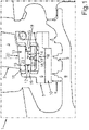
- FIG. 1 shows a schematic cross section through a vane ring.
- the guide vane ring 2 shown schematically can be the guide vane ring 2 of a turbomachine 1, with the turbomachine 1 being able in particular to be a turbine of an aircraft.
- the vane ring 2 can be provided to influence the course of an air flow, so that it impinges on rotor blades of a rotor blade ring of the turbomachine 1 at a predetermined angle.
- the vane ring 2 can have at least one vane 3 which can be arranged in a bearing body 4 .
- the bearing body 4 can be provided to enable the guide vane 3 to be mounted in an inner ring segment 6 of an inner ring 5 of the guide vane ring 2 .
- the inner ring 5 of the vane ring 2 can be provided to mechanically stabilize the vanes 3 of the vane ring 2 in an inner area of the turbomachine 1 .
- a distance 7 between the inner ring 5 and a rotor component 8 is sealed by an inner ring firn 9 and a sealing body 10 of the inner ring 5 .
- the distance 7 in order to prevent a reduction in the leakage flow in the distance 7 and also to prevent friction losses, which can occur as a result of the inner ring firn 9 rubbing against the sealing body 10, it is necessary for the distance 7 to remain constant during operation of the turbomachine 1.
- the so-called cording Due to the so-called cording, a change in the curvature of the inner ring 5 during operation, the distance 7 can increase during operation and thus a loss of efficiency occurs due to the higher leakage current between the inner ring 5 and the rotor component 8 . In the event that the distance 7 between the inner ring 5 and the rotor component 8 decreases, it can be due to friction between the inner ring firn 9 and the sealing body 10 also come to efficiency losses.
- the so-called cording can be implemented, for example, by reducing an inner angle of the inner ring segments 6 of the inner ring 5 . This makes it possible for an inner ring 5 to consist of more than two inner ring segments 6 . However, for this it is necessary to enable a more stable arrangement of the inner ring segments 6 on the guide vanes 3 .
- the invention provides for this mechanical stabilization to be made possible by directly connecting the inner ring segments 6 to the guide vanes 3 .
- a bearing journal 11 of the guide vane 3 has a journal groove 12 which can run around the bearing journal 11 .
- the bearing journal 11 can be designed in such a way that a journal radius 13 of the bearing journal 11 in an axial area outside of the journal groove 12 is twice as large as a journal groove radius 14 in an axial area of the journal groove 12.
- the bearing journal 11 can be mounted in a bearing bushing 15 of the bearing body 4 be arranged.
- the bearing body 4 can have a guide pin 16 which can engage in a bore 17 in the bearing pin 11 .
- the bore 17 can run parallel to a bearing journal axis.
- the inner ring segment 6 can have a guide channel 18 which can run along a circumferential direction around the inner ring 5 of the vane ring 2 .
- Two opposing guide projections 19 of the inner ring segment 6 can protrude into the guide channel 18 .
- the bearing body 4 can be arranged with the bearing journal 11 in the guide channel 18 in such a way that the two guide projections 19 of the inner ring segment 6 engage both in guide grooves 15 of the bearing body 4 and in the journal groove 12 of the bearing journal 11 of the guide vane 3.
- the bearing journal 11 can have two plates 21, 22, which can be an inner plate 22 and an outer plate 21.
- the inner plate 22 can be arranged closer to the inner ring 5 in the axial direction, while the outer plate 21 can be arranged closer to the guide vane 3 in the axial direction.
- the plates 21, 22 can be round to allow rotation of the vane 3 in the bearing body 4 to allow.
- the bearing body 4 can contain carbon and/or metal.
- FIG. 2 shows a further representation of the vane ring 1 .
- FIG. 3 shows a schematic three-dimensional view showing an arrangement of the bearing body in the inner ring segment.
- FIG. 4 shows the position of the guide projections 19 of the inner ring segments 6 in the journal groove 12 in order to enable the guide vane 3 to be mounted in the inner ring segment 6 .
- FIG. 4 It can be seen how the guide projections 19 of the inner ring segment 6 engage in the bearing body 4 at the guide grooves 15 in order to stabilize it in the guide channel 18 .
- the bearing bushing 20 of the bearing body 4 with a round opening to enable the guide vane 3 to rotate can also be seen.
- FIG. 5 shows how the guide projections 19 of the inner ring segment 6 engage in the journal groove 12 of the bearing journal 11 of the vane 4 and the guide grooves 15 of the bearing body 4 in order to fasten the vane 4 and the bearing body 4 in the guide channel 18.
- FIG. 6 shows a sequence of a method for installing a vane ring for a turbomachine. It can be provided that in a first step P1 of the method, the bearing journal 11 of the guide vane 3 is arranged in a form-fitting manner in the bearing bushing 20 of a bearing body 4 .
- the bearing body 4 can be threaded into the guide channel 17 running on an outer radius surface of an inner ring segment 6 along the circumferential direction of the vane ring 2 .
- the at least two opposite guide projections 19 of the inner ring segment 6 running along the circumferential direction of the vane ring 2 and protruding into the guide channel 17 can be guided into the at least two guide grooves 15 of the bearing body 4 .
- the at least two guide projections 19 of the inner ring segment 6 can be guided into the journal groove 12 of the bearing journal 11 of the guide vane 3 .
- the inner ring segments 6 can be arranged next to one another to form an inner ring 5.
- the inner ring segment 6 used as the seal carrier is not only connected to the bearing bodies 4 via the guide grooves 15, but also to the plates 21, 22 of the guide vanes 3. This means that when the seal carrier is threaded onto the bearing body 4, the Guide projections 19 or hooks of the seal carrier also the pivot groove 12, which was screwed into the plate or the bearing pin 11 of the vane 3.
- the seal carrier is thus connected radially to the bearing journal 11 of the guide vane 3 and is guided and controlled in its radial position via the guide vane 3 by the outer housing (usually the split case).
- the seal carrier therefore no longer has to be a half ring, but can also be divided into smaller segments, which therefore have less cording.
Landscapes
- Engineering & Computer Science (AREA)
- Mechanical Engineering (AREA)
- General Engineering & Computer Science (AREA)
- Turbine Rotor Nozzle Sealing (AREA)
Abstract
Die Erfindung betrifft einen Leitschaufelkranz (2) für eine Strömungsmaschine (1), aufweisend zumindest eine Leitschaufel (3), zumindest einen Lagerkörper und zumindest zwei Innenringsegmente (6). Die Leitschaufel (3) weist einen Lagerzapfen (11) auf, der formschlüssig in einer Lagerbuchse (20) des zumindest einen Lagerkörpers (4) angeordnet ist. Die zumindest zwei Innenringsegmente (6) weisen an ihren jeweiligen Außenradiusflächen, einen entlang einer Umlaufrichtung des Leitschaufelkranzes (2) verlaufenden Führungskanal (18) zur Aufnahme der Lagerkörper (4) auf, in den zumindest zwei gegenüberliegende und entlang der Umlaufrichtung des Leitschaufelkranzes (2) verlaufende Führungsvorsprünge (19) der Innenringsegmente (6) ragen. Der Lagerkörper (4) ist in dem Führungskanal (18) der Innenringsegmente (6) angeordnet, und die zumindest zwei Führungsvorsprünge (19) der Innenringsegmente (6) greifen in zumindest zwei Führungsnuten (15) des Lagerkörpers (4). Es ist vorgesehen, dass der Lagerzapfen (11) der Leitschaufel (3) eine Zapfennut (12) aufweist in welche die Führungsvorsprünge (19) des Innenringsegments (6) greifen.The invention relates to a vane ring (2) for a turbomachine (1), having at least one vane (3), at least one bearing body and at least two inner ring segments (6). The guide vane (3) has a bearing pin (11) which is arranged in a form-fitting manner in a bearing bush (20) of the at least one bearing body (4). The at least two inner ring segments (6) have on their respective outer radius surfaces a guide channel (18) running along a circumferential direction of the guide vane ring (2) for receiving the bearing bodies (4), in which at least two opposite and along the circumferential direction of the guide vane ring (2) running guide projections (19) of the inner ring segments (6) protrude. The bearing body (4) is arranged in the guide channel (18) of the inner ring segments (6), and the at least two guide projections (19) of the inner ring segments (6) engage in at least two guide grooves (15) of the bearing body (4). The bearing journal (11) of the guide vane (3) has a journal groove (12) into which the guide projections (19) of the inner ring segment (6) engage.
Description
Die Erfindung betrifft einen Leitschaufelkranz für eine Strömungsmaschine. Weitere Aspekte der Erfindung betreffen eine Strömungsmaschine, aufweisend zumindest einen Leitschaufelkranz sowie ein Verfahren zum Montieren eines Leitschaufelkranzes für eine Strömungsmaschine.The invention relates to a vane ring for a turbomachine. Further aspects of the invention relate to a turbomachine, having at least one ring of guide vanes and a method for installing a ring of guide vanes for a turbomachine.
Eine Beschaufelung einer Strömungsmaschine weist zwei Arten von Schaufeln auf, welche sich in ihren Funktionen voneinander unterscheiden. Laufschaufeln sind ein Teil des Rotors und für eine Umwandlung von Leistung vorgesehen. Die einzelnen Laufschaufeln sind dabei als Laufschaufelkranz an einer Welle des Rotors angeordnet. Leitschaufeln sind an einem Stator der Strömungsmaschine angeordnet. Die einzelnen Leitschaufeln sind dabei als Leitschaufelkranz angeordnet, welcher neben den Leitschaufeln einen Innenring aufweist. Dieser Innenring umläuft die Welle des Rotors und ist dazu vorgesehen, die einzelnen Leitschaufeln des Leitschaufelkranzes in einem Zentrum zu stabilisieren. Die einzelnen Leitschaufeln sind mit ihren radial inneren Enden in dem Innenring gelagert. Der Innenring besteht gewöhnlicherweise aus Innenringsegmenten, um eine Anordnung der radial inneren Enden während einer Montage zu ermöglichen. Die Aufgabe der Leitschaufeln besteht darin, die Strömung derart zu beeinflussen, dass diese in einem vorbestimmten Winkel auf die Laufschaufeln trifft. Leitschaufeln können dabei drehbar gelagert sein, so dass der Winkel unter welchem die Strömung auf die Laufschaufeln trifft variiert werden kann.A blading of a turbomachine has two types of blades, which differ from one another in their functions. Blades are part of the rotor and are intended for power conversion. The individual rotor blades are arranged as a rotor blade ring on a shaft of the rotor. Guide vanes are arranged on a stator of the turbomachine. The individual guide vanes are arranged as a guide vane ring, which has an inner ring in addition to the guide vanes. This inner ring runs around the shaft of the rotor and is intended to stabilize the individual guide vanes of the guide vane ring in a center. The individual guide vanes are mounted with their radially inner ends in the inner ring. The inner ring is usually made up of inner ring segments to allow location of the radially inner ends during assembly. The task of the vanes is to influence the flow in such a way that it hits the rotor blades at a predetermined angle. Guide vanes can be rotatably mounted so that the angle at which the flow hits the moving vanes can be varied.
Um eine hohe Effizienz bei Strömungsmaschinen zu gewährleisten, ist es erforderlich, eine Leckage von Strömungen im Bereich des Innenrings zu minimieren. Zu diesem Zweck weisen die Innenringsegmente des Innenrings Dichtvorrichtungen auf. Diese sind dazu vorgesehen Strömungen in Spalten zwischen den inneren Enden der Leitschaufeln und den Innenringsegmenten zu reduzieren. Um Strömungen in einem Bereich zwischen der Welle und dem Innenring zu minimieren, sind in diesem Bereich Dichtungsfirne angeordnet. Die Effizienzverluste aufgrund von Leckagen durch den Innenring können durch Dichtvorrichtungen wirkungsvoll reduziert werden. Leckströme zwischen dem Innenring und der Welle der Strömungsmaschine können durch die Dichtungsfirne nur bedingt eingeschränkt werden. Dies liegt daran, dass im Laufe eines Betriebs der Strömungsmaschine eineIn order to ensure high efficiency in turbomachines, it is necessary to minimize leakage of flows in the area of the inner ring. For this purpose, the inner ring segments of the inner ring have sealing devices. These are designed to reduce flow in gaps between the inner ends of the vanes and the inner ring segments. In order to minimize flows in an area between the shaft and the inner ring, sealing fir is arranged in this area. The efficiency losses due to leakage through the inner ring can be effectively reduced by sealing devices. Leakage flows between the inner ring and the shaft of the turbomachine can only be restricted to a limited extent by the sealing firne. This is due to the fact that in the course of operation of the turbomachine
Änderung einer Krümmung des Innenrings erfolgen kann. Dabei kann die Krümmung des Innenrings bereichsweise zu- oder abnehmen. Aufgrund der Änderung der Krümmung kann der Abstand zwischen dem Innenring und der Welle bereichsweise zu- oder abnehmen. Bei einer Zunahme des Abstandes treten erhöhte Leckströme in diesem Bereich auf, welche die Effizienz der Strömungsmaschine reduzieren. Kommt es zu einer Reduzierung des Abstandes, können die Dichtungsfirne in diesem Bereich an der Welle schleifen.Changing a curvature of the inner ring can be done. The curvature of the inner ring can increase or decrease in certain areas. Due to the change in curvature, the distance between the inner ring and the shaft can increase or decrease in areas. With an increase in the distance, increased leakage currents occur in this area, which reduce the efficiency of the turbomachine. If the distance is reduced, the sealing varnish can rub against the shaft in this area.
Diese Änderung der Krümmung wird auch als Cording bezeichnet. Eine Möglichkeit, das Cording zu reduzieren besteht darin, eine Anzahl der Innenringsegmente, aus welchen sich der Innenring zusammensetzt zu erhöhen. Dabei ergibt sich jedoch das Problem, dass die mechanische Stabilität der Lagerung des Innenrings durch die Leitschaufeln abnehmen kann.This change in curvature is also referred to as cording. One way to reduce cording is to increase a number of the inner ring segments that make up the inner ring. However, the problem arises that the mechanical stability of the bearing of the inner ring can decrease due to the guide vanes.
In der
In der
Die
Die
In der
Die
Die
Die
Es ist eine Aufgabe der Erfindung, eine Lösung bereitzustellen, welche eine stabile Lagerung des Innenrings durch Leitschaufeln ermöglicht.It is an object of the invention to provide a solution which enables the inner ring to be stably supported by guide vanes.
Diese Aufgabe wird durch einen Leitschaufelkranz für eine Strömungsmaschine mit den Merkmalen des Patentanspruchs 1, durch eine Strömungsmaschine mit den Merkmalen des Patentanspruchs 9 sowie durch ein Verfahren zur Montage einer Strömungsmaschine mit den Merkmalen des Patentanspruchs 10 gelöst. Vorteilhafte Ausgestaltungen mit zweckmäßigen Weiterbildungen der Erfindung sind in den jeweiligen Unteransprüchen angegeben.This object is achieved by a vane ring for a turbomachine with the features of patent claim 1, by a turbomachine with the features of
Ein erster Aspekt der Erfindung betrifft einen Leitschaufelkranz für eine Strömungsmaschine. Bei der Strömungsmaschine kann es sich insbesondere um eine Turbine für ein Flugzeug handeln. Der Leitschaufelkranz weist zumindest eine Leitschaufel, zumindest einen Lagerkörper und zumindest zwei Innenringsegmente auf. Bei der Leitschaufel kann es sich um eine Schaufel handeln, welche dazu eingerichtet sein kann, einen Luftstrom derart zu leiten, dass dieser in einem vorbestimmten Winkel auf eine Laufschaufel auftrifft. Die Leitschaufel kann drehbar gelagert sein, um einen Winkel des Stroms variabel verändern zu können. Der Lagerkörper ist dazu vorgesehen, die Leitschaufel aufzunehmen und somit eine Lagerung der Leitschaufeln in den zumindest zwei Innenringsegmenten zu ermöglichen. Die Innenringsegmente sind dazu vorgesehen, radial innere Enden der Leitschaufel mechanisch zu stabilisieren und somit einen stabilen Betrieb des Leitschaufelkranzes zu ermöglichen.A first aspect of the invention relates to a vane ring for a turbomachine. The turbomachine can in particular be a turbine for an aircraft. The vane ring has at least one vane, at least one bearing body and at least two inner ring segments. The guide vane can be a vane which can be configured to guide an air flow in such a way that it impinges on a moving vane at a predetermined angle. The guide vane can be rotatably mounted in order to be able to variably change an angle of the flow. The bearing body is intended to accommodate the guide vane and thus enable the guide vanes to be mounted in the at least two inner ring segments. The inner ring segments are intended to mechanically stabilize radially inner ends of the guide vane and thus enable stable operation of the guide vane ring.
Die Leitschaufel weist einen Lagerzapfen auf, der formschlüssig in einer Lagerbuchse des zumindest einen Lagerkörpers angeordnet ist. Mit anderen Worten weist die Leitschaufel einen verjüngten Abschnitt an einem ihrem radial inneren Ende auf, der dazu vorgesehen ist, eine Lagerung der Leitschaufel in dem Lagerkörper zu ermöglichen. Der Lagerzapfen kann beispielsweise zylinderförmig sein. Der Lagerzapfen der Leitschaufel ist dabei in der Lagerbuchse des Lagerkörpers angeordnet. Die Lagerbuchse kann beispielsweise komplementär zu einer Form des Lagerzapfens gestaltet sein.The guide vane has a bearing journal which is arranged in a form-fitting manner in a bearing bushing of the at least one bearing body. In other words, the guide vane has a tapered section at one of its radially inner ends, which is provided to enable the guide vane to be mounted in the bearing body. The bearing journal can be cylindrical, for example. The bearing journal of the vane is arranged in the bearing bush of the bearing body. The bearing bush can, for example, be designed to complement a shape of the bearing journal.
Die zumindest zwei Innenringsegmente weisen an jeweiligen Außenradiusflächen einen entlang einer Umlaufrichtung des Leitschaufelkranzes verlaufenden Führungskanal zur Aufnahme der Lagerkörper auf, in den zumindest zwei gegenüberliegende und entlang der Umlaufrichtung des Leitschaufelkranzes verlaufende Führungsvorsprünge der Innenringsegmente ragen. Die zumindest zwei Innenringsegmente können den Innenring des Leitschaufelkranzes bilden. Mit anderen Worten weisen die Innenringsegmente den Führungskanal aufweisen, welcher entlang der Umlaufrichtung des Leitschaufelkranzes um den Innenring verläuft, um eine Anordnung der Leitschaufeln in dem Innenring zu ermöglichen. Der Führungskanal kann dabei auf jeweiligen Außenradiusflächen des Innenrings angeordnet sein. Mit anderen Worten ist der Führungskanal in einer radial nach außen gerichteten Fläche des Innenrings ausgerichtet. Der Führungskanal weist zumindest zwei gegenüberliegende und entlang der Umlaufrichtung des Leitschaufelkranzes verlaufende Führungsvorsprünge auf. Die Führungsvorsprünge sind dazu eingerichtet, eine formschlüssige Lagerung des Lagerkörpers in dem Führungskanal zu ermöglichen. Der Lagerkörper ist in den Führungskanal der Innenringsegmente angeordnet. Die zumindest zwei Führungsvorsprünge der Innenringsegmente greifen in zumindest zwei Führungsnuten des Lagerkörpers. Mit anderen Worten ist der Lagerkörper derart in dem Führungskanal angeordnet, dass die zwei Führungsvorsprünge der Innenringsegmente in die zumindest zwei Führungsnuten des Lagerkörpers greifen.The at least two inner ring segments have on respective outer radius surfaces a guide channel running along a circumferential direction of the vane ring for receiving the bearing bodies, into which at least two opposite guide projections of the inner ring segments running along the circumferential direction of the vane ring protrude. The at least two inner ring segments can form the inner ring of the vane ring. In other words, the inner ring segments have the guide channel, which runs along the circumferential direction of the guide vane ring runs around the inner ring in order to enable the guide vanes to be arranged in the inner ring. The guide channel can be arranged on the respective outer radius surfaces of the inner ring. In other words, the guide channel is aligned in a radially outwardly directed surface of the inner ring. The guide channel has at least two opposite guide projections running along the circumferential direction of the vane ring. The guide projections are set up to enable the bearing body to be mounted in a form-fitting manner in the guide channel. The bearing body is arranged in the guide channel of the inner ring segments. The at least two guide projections of the inner ring segments engage in at least two guide grooves of the bearing body. In other words, the bearing body is arranged in the guide channel in such a way that the two guide projections of the inner ring segments engage in the at least two guide grooves of the bearing body.
Es ist vorgesehen, dass der Lagerzapfen der Leitschaufel eine Zapfennut aufweist, in welche die Führungsvorsprünge des Innenringsegments greifen. Mit anderen Worten ist es vorgesehen, dass die Führungsvorsprünge der Innenringsegmente sowohl in die Führungsnuten des Lagerkörpers, als auch in die Zapfennut des Lagerzapfens der Leitschaufel greifen. Dadurch ergibt sich der Vorteil, dass der Lagerzapfen der Leitschaufel direkt mit dem Innenringsegment verbunden ist. Dadurch kann eine stabilere mechanische Verbindung zwischen der Leitschaufel und dem Innenringsegment erreicht sein als bei üblichen Verbindungen über den Lagerkörper.Provision is made for the bearing journal of the guide vane to have a journal groove into which the guide projections of the inner ring segment engage. In other words, it is provided that the guide projections of the inner ring segments engage both in the guide grooves of the bearing body and in the journal groove of the bearing journal of the vane. This results in the advantage that the bearing journal of the guide vane is connected directly to the inner ring segment. As a result, a more stable mechanical connection can be achieved between the guide vane and the inner ring segment than with conventional connections via the bearing body.
Eine Weiterbildung der Erfindung sieht vor, dass die Zapfennut um eine Lagerzapfenlängsachse des Lagerzapfens verläuft. Mit anderen Worten ist es vorgesehen, dass die Zapfennut um den Lagerzapfen herum verläuft. Es kann beispielsweise vorgesehen sein, dass der Lagerzapfen radialsymmetrisch ist und einen um einen gesamten Umlauf des Lagerzapfens verlaufende Ausnehmung als die Zapfennut aufweist.A further development of the invention provides that the journal groove runs around a longitudinal axis of the bearing journal. In other words, it is provided that the journal groove runs around the bearing journal. Provision can be made, for example, for the bearing journal to be radially symmetrical and to have a recess running around the entire circumference of the bearing journal as the journal groove.
Eine Weiterbildung der Erfindung sieht vor, dass ein Zapfennutradius des Lagerzapfens in einem Längsbereich der jeweiligen Zapfennut höchstens halb so groß ist wie ein Zapfenradius außerhalb der Zapfennut. Mit anderen Worten weist der Lagerzapfen im Bereich der Zapfennut einen Radius auf, der höchstens halb so groß ist wie der Radius des Lagerzapfens außerhalb der Zapfennut. Eine Weiterbildung der Erfindung sieht vor, dass der Lagerzapfen einen inneren Leitschaufelteller und einen äußeren Leitschaufelteller aufweist, welche durch die Zapfennut voneinander getrennt sind. Durch die Weiterbildung ergibt sich der Vorteil, dass die zwei Leitschaufelteller eine vorbestimmte Lagerung des Lagerzapfens in dem Lagerkörper und dem Innenringsegment ermöglichen.A development of the invention provides that a journal groove radius of the bearing journal in a longitudinal region of the respective journal groove is at most half as large as a journal radius outside of the journal groove. In other words, the bearing journal has a radius in the region of the journal groove which is at most half the size of the radius of the bearing journal outside of the journal groove. A further development of the invention provides that the bearing journal has an inner vane plate and an outer vane plate, which are separated from one another by the journal groove. The further development results in the advantage that the two guide vane disks enable a predetermined mounting of the bearing journal in the bearing body and the inner ring segment.
Eine Weiterbildung der Erfindung sieht vor, dass der Lagerzapfen an einem axialen Lagerzapfenende eine parallel zur Lagerzapfenachse verlaufende Bohrung aufweist, welche einen Stift des Lagerkörpers aufnimmt. Mit anderen Worten befindet sich an einem Ende des Lagerzapfens eine Bohrung, in welcher ein Stift des Lagerkörpers angeordnet ist. Durch die Weiterbildung ergibt sich der Vorteil, dass eine zentrierte Anordnung des Lagerzapfens in der Lagerbuchse des Lagerkörpers ermöglicht ist.A further development of the invention provides that the bearing journal has, at one axial bearing journal end, a bore which runs parallel to the bearing journal axis and which accommodates a pin of the bearing body. In other words, there is a bore at one end of the bearing journal, in which a pin of the bearing body is arranged. The further development results in the advantage that a centered arrangement of the bearing journal in the bearing bush of the bearing body is made possible.
Eine Weiterbildung der Erfindung sieht vor, dass die Innenringsegmente einen Mittelpunktswinkel von 30 Grad, 45 Grad, 60 Grad, 90 Grad oder 180 Grad aufweisen. Mit anderen Worten ist es vorgesehen, dass die Innenringsegmente eine Krümmung aufweisen, so dass sich der Innenring aus 12, 8, 6, 4 oder 2 Innenringsegmenten zusammensetzt. Durch die Weiterbildung ergibt sich der Vorteil, dass der Innenring aus mehreren der Innenringsegmente zusammengesetzt ist, wodurch Krümmungsänderungen aufgrund des Cordings reduziert sein können.A development of the invention provides that the inner ring segments have a central angle of 30 degrees, 45 degrees, 60 degrees, 90 degrees or 180 degrees. In other words, it is provided that the inner ring segments have a curvature, so that the inner ring is composed of 12, 8, 6, 4 or 2 inner ring segments. The further development results in the advantage that the inner ring is composed of several of the inner ring segments, as a result of which changes in curvature due to the cording can be reduced.
Eine Weiterbildung der Erfindung sieht vor, dass der Lagerkörper zumindest teilweise aus Metall und/oder einem Carbon besteht. Mit anderen Worten weist der Lagerkörper eine Legierung aus Metall und/oder Carbon auf.A development of the invention provides that the bearing body consists at least partially of metal and/or carbon. In other words, the bearing body has an alloy of metal and/or carbon.
Eine Weiterbildung der Erfindung sieht vor, dass an den Innenradien der Innenringsegmente Dichtungskörper angeordnet sind. Mit anderen Worten ist es vorgesehen, dass der Innenring an einer der Welle eines Rotors zugewandten Seite Dichtungskörper aufweist, welche einen Luftstrom in einem Bereich zwischen dem Innenring und der Welle reduzieren. Dadurch ergibt sich der Vorteil, dass eine Effizienz der Strömungsmaschine erhöht werden kann.A development of the invention provides that sealing bodies are arranged on the inner radii of the inner ring segments. In other words, it is provided that the inner ring has sealing bodies on a side facing the shaft of a rotor, which seal bodies reduce an air flow in a region between the inner ring and the shaft. This results in the advantage that the efficiency of the turbomachine can be increased.
Ein zweiter Aspekt der Erfindung betrifft eine Strömungsmaschine, welche zumindest einen Leitschaufelkranz aufweist. Bei der Strömungsmaschine kann es sich insbesondere um eine Strömungsmaschine eines Flugzeugs, beispielsweise eine Flugzeugturbine handeln.A second aspect of the invention relates to a turbomachine which has at least one ring of guide vanes. The turbomachine can in particular be a turbomachine of an aircraft, for example an aircraft turbine.
Ein dritter Aspekt der Erfindung betrifft ein Verfahren zum Montieren eines Leitschaufelkranzes für eine Strömungsmaschine. Es ist vorgesehen, dass in einem Schritt des Verfahrens ein formschlüssiges Anordnen eines Lagerzapfens einer Leitschaufel in einer Lagerbuchse eines Lagerkörpers durchgeführt wird. Der Lagerkörper wird in einem, an einer Außenradiusfläche eines Innenringsegments entlang einer Umlaufrichtung des Leitschaufelkranzes verlaufenden Führungskanal aufgefädelt, wobei zumindest zwei gegenüber liegende und entlang der Umlaufrichtung des Leitschaufelkranzes verlaufende und in den Führungskanal ragende Führungsvorsprünge des Innenringsegments in zumindest zwei Führungsnuten des Lagerkörpers geführt werden und die zumindest zwei Führungsvorsprünge des Innenringsegments in eine Zapfennut des Lagerzapfens der Leitschaufel geführt werden. Die Innenringsegmente werden aneinander zu einem Innenring angeordnet.A third aspect of the invention relates to a method for installing a vane ring for a turbomachine. It is provided that in one step of the method, a bearing journal of a guide vane is arranged in a form-fitting manner in a bearing bushing of a bearing body. The bearing body is threaded into a guide channel running on an outer radius surface of an inner ring segment along a circumferential direction of the vane ring, with at least two opposite guide projections of the inner ring segment running along the circumferential direction of the vane ring and protruding into the guide channel being guided in at least two guide grooves of the bearing body and the at least two guide projections of the inner ring segment are guided into a journal groove of the bearing journal of the vane. The inner ring segments are arranged together to form an inner ring.
Die im Zusammenhang mit dem Leitschaufelkranz gemäß dem ersten Aspekt der Erfindung und der Strömungsmaschine gemäß dem zweiten Aspekt der Erfindung vorgestellten Merkmale sowie deren Vorteile gelten entsprechend für das erfindungsgemäße Verfahren zum Montieren eines Leitschaufelkranzes gemäß dem dritten Aspekt der Erfindung und umgekehrt.The features presented in connection with the vane ring according to the first aspect of the invention and the turbomachine according to the second aspect of the invention and their advantages apply correspondingly to the inventive method for assembling a vane ring according to the third aspect of the invention and vice versa.
Weitere Merkmale der Erfindung ergeben sich aus den Ansprüchen und den Ausführungsbeispielen. Die vorstehend in der Beschreibung genannten Merkmale und Merkmalskombinationen, sowie die nachfolgend in den Ausführungsbeispielen genannten und/oder alleine gezeigten Merkmale und Merkmalskombinationen sind nicht nur in der jeweils angegebenen Kombination, sondern auch in anderen Kombinationen oder in Alleinstellung verwendbar, ohne den Rahmen der Erfindung zu verlassen. Es sind somit auch Ausführungen von der Erfindung als umfasst und offenbart anzusehen, die in den Ausführungsbeispielen nicht explizit gezeigt und erläutert sind, jedoch durch separierte Merkmalskombinationen aus den erläuterten Ausführungen hervorgehen und erzeugbar sind. Es sind auch Ausführungen und Merkmalskombinationen als offenbart anzusehen, die somit nicht alle Merkmale eines ursprünglich formulierten unabhängigen Anspruchs aufweisen. Dabei zeigt:
-
FIG. 1 einen schematischen Querschnitt durch einen Leitschaufelkranz; -
FIG. 2 eine weitere Darstellung des Leitschaufelkranzes derFig. 1 . -
FIG. 3 eine schematische dreidimensionale Ansicht, welche eine Anordnung des Lagerkörpers in dem Innenringsegment darstellt; -
FIG. 4 die Lage der Führungsvorsprünge der Innenringsegmente in der Zapfennut; und -
FIG. 5 wie die Führungsvorsprünge des Innenringsegments in die Führungsnut der Leitschaufel und die Führungsnuten des Lagerkörpers greifen.
-
FIG. 1 a schematic cross section through a vane ring; -
FIG. 2 another representation of the vane ring of1 . -
FIG. 3 a schematic three-dimensional view showing an arrangement of the bearing body in the inner ring segment; -
FIG. 4 the position of the guide projections of the inner ring segments in the journal groove; and -
FIG. 5 how the guide projections of the inner ring segment engage in the guide groove of the vane and the guide grooves of the bearing body.
Zu diesem Zweck kann es vorgesehen sein, dass ein Lagerzapfen 11 der Leitschaufel 3 eine Zapfennut 12 aufweist, welche um den Lagerzapfen 11 verlaufen kann. Der Lagerzapfen 11 kann dabei derart gestaltet sein, dass ein Zapfenradius 13 des Lagerzapfens 11 in einem Axialbereich außerhalb der Zapfennut 12 doppelt so groß ist wie ein Zapfennutradius 14 in einem axialen Bereich der Zapfennut 12. Der Lagerzapfen 11 kann in einer Lagerbuchse 15 des Lagerkörpers 4 angeordnet sein. Um eine optimale Anordnung des Lagerzapfens 11 in dem Lagerkörper 4 zu ermöglichen, kann der Lagerkörper 4 einen Führungsstift 16 aufweisen, welcher in eine Bohrung 17 des Lagerzapfens 11 greifen kann. Die Bohrung 17 kann parallel zu einer Lagerzapfenachse verlaufen. Um eine Anordnung des Lagerkörpers 4 in dem Innenringsegment 6 zu ermöglichen, kann das Innenringsegment 6 einen Führungskanal 18 aufweisen, welcher entlang einer Umlaufrichtung um den Innenring 5 des Leitschaufelkranzes 2 verlaufen kann. In den Führungskanal 18 können zwei gegenüber liegende Führungsvorsprünge 19 des Innenringsegments 6 hineinragen. In einem zusammengebauten Zustand kann der Lagerkörper 4 mit dem Lagerzapfen 11 derart in dem Führungskanal 18 angeordnet sein, dass die zwei Führungsvorsprünge 19 des Innenringsegments 6 sowohl in Führungsnuten 15 des Lagerkörpers 4, als auch in die Zapfennut 12 des Lagerzapfens 11 der Leitschaufel 3 greifen. Dadurch besteht eine direkte mechanische Verbindung, zwischen der Leitschaufel 3 und dem Innenringsegment 6 wodurch eine mechanisch stabilere Lagerung der Innenringsegmente 6 an den Leitschaufeln 3 ermöglicht ist. Dadurch ist es möglich, die Größe der Innenringsegmente 6 zu reduzieren, so dass diese beispielsweise Mittelpunktswinkel von 30 Grad, 45 Grad, 60 Grad, 90 Grad oder 180 Grad einschließen. Durch die Zapfennut 12 des Lagerzapfens 11 kann der Lagerzapfen 11 zwei Teller 21, 22 aufweisen, wobei es sich um einen inneren Teller 22 und einen äußeren Teller 21 handeln kann. Der innere Teller 22 kann dabei in axialer Richtung näher am Innenring 5 angeordnet sein, während der äußere Teller 21 in axialer Richtung näher an der Leitschaufel 3 angeordnet sein kann. Die Teller 21, 22 können rund sein, um eine Drehung der Leitschaufel 3 in dem Lagerkörper 4 zu ermöglichen. Der Lagerkörper 4 kann Carbon und/oder Metall enthalten.For this purpose it can be provided that a
Der Lagerkörper 4 kann in einem zweiten Schritt P2 in dem, an einer Außenradiusfläche eines Innenringsegments 6 entlang der Umlaufrichtung des Leitschaufelkranzes 2 verlaufenden Führungskanal 17 aufgefädelt werden. Dabei können die zumindest zwei gegenüber liegende und entlang der Umlaufrichtung des Leitschaufelkranzes 2 verlaufende und in den Führungskanal 17 ragende Führungsvorsprünge 19 des Innenringsegments 6 in die zumindest zwei Führungsnuten 15 des Lagerkörpers 4 geführt werden. Zugleich können die zumindest zwei Führungsvorsprünge 19 des Innenringsegments 6 in die Zapfennut 12 des Lagerzapfens 11 der Leitschaufel 3 geführt werden.In a second step P2, the bearing
In einem dritten Schritt P3 können die Innenringsegmente 6 aneinander zu einem Innenring 5 angeordnet werden.In a third step P3, the
In dem Stand der Technik wird zwar die Reduzierung der Leitschaufeltellerleckage, sowie die mögliche Miniaturisierung der Geometrie für zukünftige kleine Verdichtergrößen gelöst, nicht aber das Problem des Cordings, das Entkrümmens beziehungsweise das Überkrümmen des Innenring-Halbringes. Das Cording kann zu starken Spaltschwankungen im Bereich der Trennebenen des Innenrings 5 führen. Diese Spaltschwankungen führen bei Öffnung durch erhöhte Leckagen zu einem Wirkungsgradabfall, beziehungsweise bei erhöhter Spaltschließung zu einer Überlastung der Einlauffähigkeit des Innenringfirns 9.Although the prior art solves the reduction in guide vane plate leakage and the possible miniaturization of the geometry for future small compressor sizes, the problem of cording, the uncurling or overcurving of the inner ring half-ring is not. The cording can lead to strong gap fluctuations in the area of the parting planes of the inner ring 5 . When opening, these gap fluctuations lead to a drop in efficiency due to increased leakage, or when the gap closes to an overload of the inlet capacity of the
In der hier beschriebenen Idee wird das als Dichtungsträger verwendete Innenringsegment 6 nicht nur über die Führungsnuten 15 mit den Lagerkörpern 4 verbunden, sondern gleichzeitig mit den Tellern 21, 22 der Leitschaufeln 3. Das bedeutet, dass beim Auffädeln des Dichtungsträgers auf die Lagerköper 4 durchdringen die Führungsvorsprünge 19 oder Haken des Dichtungsträgers auch die Zapfennut 12, die in den Teller oder dem Lagerzapfen 11 der Leitschaufel 3 eingedreht wurde. Damit ist der Dichtungsträger radial mit dem Lagerzapfen 11 der Leitschaufel 3 verbunden und wird in seiner radialen Lage so über die Leitschaufel 3 vom Außengehäuse (in der Regel dem Splitcase) geführt und gesteuert. Der Dichtungsträger muss somit nicht mehr zwingend ein Halbring sein, sondern kann auch in kleinere Segmente geteilt werden, die somit weniger Cording aufweisen.In the idea described here, the
- 11
- Strömungsmaschineflow machine
- 22
- Leitschaufelkranzvane ring
- 33
- Leitschaufelvane
- 44
- Lagerköperbearing body
- 55
- Innenringinner ring
- 66
- Innenringsegmentinner ring segment
- 77
- AbstandDistance
- 88th
- Rotorkomponenterotor component
- 99
- Innenringfirninner ring firn
- 1010
- Dichtungskörperseal body
- 1111
- Lagerzapfenbearing journal
- 1212
- Zapfennuttenon groove
- 1313
- Zapfenradiusspigot radius
- 1414
- Zapfennutradiustenon groove radius
- 1515
- Führungsnutenguide grooves
- 1616
- Führungsstiftguide pin
- 1717
- Bohrungdrilling
- 1818
- Führungskanalguide channel
- 1919
- Führungsvorsprüngeguide protrusions
- 2020
- Lagerbuchsebearing bush
- 2121
- Äußerer Tellerouter plate
- 2222
- Innerer Tellerinner plate
- P1P1
- Verfahrensschrittprocess step
- P2p2
- Verfahrensschrittprocess step
- P3P3
- Verfahrensschrittprocess step
Claims (10)
der Lagerzapfen (11) der Leitschaufel (3) zumindest eine Zapfennut (12) aufweist in welche zumindest einer der Führungsvorsprünge (19) des Innenringsegments (6) greift.Guide vane ring (2) for a turbomachine (1), having at least one guide vane (3), at least one bearing body and at least two inner ring segments (6), wherein
the bearing journal (11) of the guide vane (3) has at least one journal groove (12) in which at least one of the guide projections (19) of the inner ring segment (6) engages.
Applications Claiming Priority (1)
| Application Number | Priority Date | Filing Date | Title |
|---|---|---|---|
| DE102021120384.8A DE102021120384A1 (en) | 2021-08-05 | 2021-08-05 | Guide vane ring for a turbomachine, turbomachine and method for assembling a guide vane ring |
Publications (1)
| Publication Number | Publication Date |
|---|---|
| EP4130435A1 true EP4130435A1 (en) | 2023-02-08 |
Family
ID=82786660
Family Applications (1)
| Application Number | Title | Priority Date | Filing Date |
|---|---|---|---|
| EP22188200.4A Withdrawn EP4130435A1 (en) | 2021-08-05 | 2022-08-02 | Guide vane ring for a turbomachine, turbomachine and method for assembling a guide vane ring |
Country Status (3)
| Country | Link |
|---|---|
| US (1) | US20230099406A1 (en) |
| EP (1) | EP4130435A1 (en) |
| DE (1) | DE102021120384A1 (en) |
Citations (11)
| Publication number | Priority date | Publication date | Assignee | Title |
|---|---|---|---|---|
| EP0696675A1 (en) * | 1994-08-10 | 1996-02-14 | Societe Nationale D'etude Et De Construction De Moteurs D'aviation "Snecma" | Assembly device for a circular row of variable guide vanes |
| FR2775731A1 (en) * | 1998-03-05 | 1999-09-10 | Snecma | Mounting for fixed circular stage blades of turbine e.g. aircraft turbine |
| US6210106B1 (en) | 1999-04-30 | 2001-04-03 | General Electric Company | Seal apparatus for gas turbine engine variable vane |
| EP1586744A2 (en) * | 2004-04-14 | 2005-10-19 | General Electric Company | Variable vane assembly for a gas turbine engine |
| EP2093380A2 (en) * | 2008-02-20 | 2009-08-26 | United Technologies Corporation | Single channel inner diameter shroud with lightweight inner core in a gas turbine |
| EP2696041A1 (en) | 2012-08-07 | 2014-02-12 | MTU Aero Engines GmbH | Guide blade assembly of a gas turbine and assembly method |
| US8858165B2 (en) | 2010-09-30 | 2014-10-14 | Rolls-Royce Corporation | Seal arrangement for variable vane |
| US20160376900A1 (en) | 2015-06-25 | 2016-12-29 | Rolls-Royce Deutschland Ltd & Co Kg | Stator device for a continuous-flow machine with a housing appliance and multiple guide vanes |
| EP3170987A1 (en) * | 2015-11-17 | 2017-05-24 | MTU Aero Engines GmbH | Internal ring system for turbomachinery |
| EP3315728A1 (en) | 2016-10-26 | 2018-05-02 | MTU Aero Engines GmbH | Gedämpfte leitschaufellagerung |
| US10494944B2 (en) | 2017-03-23 | 2019-12-03 | MTU Aero Engines AG | Seal on the inner ring of a guide vane |
Family Cites Families (1)
| Publication number | Priority date | Publication date | Assignee | Title |
|---|---|---|---|---|
| DE102013203870B4 (en) | 2013-03-07 | 2015-06-03 | MTU Aero Engines AG | Anti-twist device for turbomachinery |
-
2021
- 2021-08-05 DE DE102021120384.8A patent/DE102021120384A1/en not_active Withdrawn
-
2022
- 2022-08-02 EP EP22188200.4A patent/EP4130435A1/en not_active Withdrawn
- 2022-08-03 US US17/817,159 patent/US20230099406A1/en not_active Abandoned
Patent Citations (13)
| Publication number | Priority date | Publication date | Assignee | Title |
|---|---|---|---|---|
| EP0696675A1 (en) * | 1994-08-10 | 1996-02-14 | Societe Nationale D'etude Et De Construction De Moteurs D'aviation "Snecma" | Assembly device for a circular row of variable guide vanes |
| FR2775731A1 (en) * | 1998-03-05 | 1999-09-10 | Snecma | Mounting for fixed circular stage blades of turbine e.g. aircraft turbine |
| US6210106B1 (en) | 1999-04-30 | 2001-04-03 | General Electric Company | Seal apparatus for gas turbine engine variable vane |
| EP1586744A2 (en) * | 2004-04-14 | 2005-10-19 | General Electric Company | Variable vane assembly for a gas turbine engine |
| EP2093380A2 (en) * | 2008-02-20 | 2009-08-26 | United Technologies Corporation | Single channel inner diameter shroud with lightweight inner core in a gas turbine |
| US8858165B2 (en) | 2010-09-30 | 2014-10-14 | Rolls-Royce Corporation | Seal arrangement for variable vane |
| US20140044526A1 (en) | 2012-08-07 | 2014-02-13 | MTU Aero Engines AG | Stationary blade ring, assembly method and turbomachine |
| EP2696041A1 (en) | 2012-08-07 | 2014-02-12 | MTU Aero Engines GmbH | Guide blade assembly of a gas turbine and assembly method |
| US9605549B2 (en) | 2012-08-07 | 2017-03-28 | MTU Aero Engines AG | Stationary blade ring, assembly method and turbomachine |
| US20160376900A1 (en) | 2015-06-25 | 2016-12-29 | Rolls-Royce Deutschland Ltd & Co Kg | Stator device for a continuous-flow machine with a housing appliance and multiple guide vanes |
| EP3170987A1 (en) * | 2015-11-17 | 2017-05-24 | MTU Aero Engines GmbH | Internal ring system for turbomachinery |
| EP3315728A1 (en) | 2016-10-26 | 2018-05-02 | MTU Aero Engines GmbH | Gedämpfte leitschaufellagerung |
| US10494944B2 (en) | 2017-03-23 | 2019-12-03 | MTU Aero Engines AG | Seal on the inner ring of a guide vane |
Also Published As
| Publication number | Publication date |
|---|---|
| US20230099406A1 (en) | 2023-03-30 |
| DE102021120384A1 (en) | 2023-02-09 |
Similar Documents
| Publication | Publication Date | Title |
|---|---|---|
| DE19518203C2 (en) | Device for receiving an inner guide vane end in an axial compressor | |
| EP0204033B1 (en) | Turbo machine | |
| DE69819290T2 (en) | AIR SEPARATOR FOR GAS TURBINES | |
| EP3032037B1 (en) | Guide vane assembly and turbo machine | |
| DE602004002049T2 (en) | Low-pressure turbine of a turbomachine | |
| EP3070270B1 (en) | Stator vane for rotary machine having a sealing device, stator and flow engine | |
| EP1148209B1 (en) | Interstage seal configuration | |
| DE2801206A1 (en) | SPIRAL DEVICE WITH A FIXED CRANE DRIVE MECHANISM | |
| DE102008032661A1 (en) | flow machine | |
| EP3409897B1 (en) | Seal assembly for a turbomachine, method for producing a seal assembly and turbomachine | |
| DE3201862A1 (en) | "TOUCH-FREE SEAL" | |
| EP1653049B1 (en) | Vane ring assembly for gas turbines and method to modify the same | |
| EP3287608B1 (en) | Internal ring for a guide- blade rim of a turbomachine | |
| WO2000000719A1 (en) | Rotor for a turbomachine | |
| EP0131719A2 (en) | Adjustable guiding apparatus | |
| EP3379037B1 (en) | Seal on the inner ring of a guide blade assembly | |
| EP3176386B1 (en) | Inner shroud assembly, corresponding inner shroud, inner casing and turbomachine | |
| EP3208426A1 (en) | Guide blade formation for a flow machine | |
| EP3203035B1 (en) | Blade system for a flow machine | |
| EP2716874B1 (en) | Guide blade assembly, assembly method and fluid flow engine | |
| EP4130435A1 (en) | Guide vane ring for a turbomachine, turbomachine and method for assembling a guide vane ring | |
| EP3315729A1 (en) | Ellipsoidal internal guide vane bearing | |
| EP3312388A1 (en) | Pultdach dichtfin | |
| EP3246529B1 (en) | Guide vane, corresponding guide vane ring and assembly method | |
| EP3875736A1 (en) | Sealing device for a turbomachine, carrier ring for a sealing device and turbomachine |
Legal Events
| Date | Code | Title | Description |
|---|---|---|---|
| PUAI | Public reference made under article 153(3) epc to a published international application that has entered the european phase |
Free format text: ORIGINAL CODE: 0009012 |
|
| STAA | Information on the status of an ep patent application or granted ep patent |
Free format text: STATUS: THE APPLICATION HAS BEEN PUBLISHED |
|
| AK | Designated contracting states |
Kind code of ref document: A1 Designated state(s): AL AT BE BG CH CY CZ DE DK EE ES FI FR GB GR HR HU IE IS IT LI LT LU LV MC MK MT NL NO PL PT RO RS SE SI SK SM TR |
|
| STAA | Information on the status of an ep patent application or granted ep patent |
Free format text: STATUS: THE APPLICATION IS DEEMED TO BE WITHDRAWN |
|
| 18D | Application deemed to be withdrawn |
Effective date: 20230809 |