EP4130399A1 - Remote control system for work machine - Google Patents
Remote control system for work machine Download PDFInfo
- Publication number
- EP4130399A1 EP4130399A1 EP21774630.4A EP21774630A EP4130399A1 EP 4130399 A1 EP4130399 A1 EP 4130399A1 EP 21774630 A EP21774630 A EP 21774630A EP 4130399 A1 EP4130399 A1 EP 4130399A1
- Authority
- EP
- European Patent Office
- Prior art keywords
- command
- actuators
- remote controller
- work machine
- communication
- Prior art date
- Legal status (The legal status is an assumption and is not a legal conclusion. Google has not performed a legal analysis and makes no representation as to the accuracy of the status listed.)
- Granted
Links
Images









Classifications
-
- G—PHYSICS
- G05—CONTROLLING; REGULATING
- G05D—SYSTEMS FOR CONTROLLING OR REGULATING NON-ELECTRIC VARIABLES
- G05D1/00—Control of position, course, altitude or attitude of land, water, air or space vehicles, e.g. using automatic pilots
- G05D1/0011—Control of position, course, altitude or attitude of land, water, air or space vehicles, e.g. using automatic pilots associated with a remote control arrangement
- G05D1/0022—Control of position, course, altitude or attitude of land, water, air or space vehicles, e.g. using automatic pilots associated with a remote control arrangement characterised by the communication link
-
- G—PHYSICS
- G05—CONTROLLING; REGULATING
- G05B—CONTROL OR REGULATING SYSTEMS IN GENERAL; FUNCTIONAL ELEMENTS OF SUCH SYSTEMS; MONITORING OR TESTING ARRANGEMENTS FOR SUCH SYSTEMS OR ELEMENTS
- G05B19/00—Program-control systems
- G05B19/02—Program-control systems electric
- G05B19/04—Program control other than numerical control, i.e. in sequence controllers or logic controllers
- G05B19/042—Program control other than numerical control, i.e. in sequence controllers or logic controllers using digital processors
- G05B19/0423—Input/output
-
- E—FIXED CONSTRUCTIONS
- E02—HYDRAULIC ENGINEERING; FOUNDATIONS; SOIL SHIFTING
- E02F—DREDGING; SOIL-SHIFTING
- E02F9/00—Component parts of dredgers or soil-shifting machines, not restricted to one of the kinds covered by groups E02F3/00 - E02F7/00
- E02F9/20—Drives; Control devices
- E02F9/2025—Particular purposes of control systems not otherwise provided for
- E02F9/205—Remotely operated machines, e.g. unmanned vehicles
-
- E—FIXED CONSTRUCTIONS
- E02—HYDRAULIC ENGINEERING; FOUNDATIONS; SOIL SHIFTING
- E02F—DREDGING; SOIL-SHIFTING
- E02F3/00—Dredgers; Soil-shifting machines
- E02F3/04—Dredgers; Soil-shifting machines mechanically-driven
- E02F3/28—Dredgers; Soil-shifting machines mechanically-driven with digging tools mounted on a dipper- or bucket-arm, i.e. there is either one arm or a pair of arms, e.g. dippers, buckets
- E02F3/36—Component parts
- E02F3/42—Drives for dippers, buckets, dipper-arms or bucket-arms
- E02F3/43—Control of dipper or bucket position; Control of sequence of drive operations
-
- E—FIXED CONSTRUCTIONS
- E02—HYDRAULIC ENGINEERING; FOUNDATIONS; SOIL SHIFTING
- E02F—DREDGING; SOIL-SHIFTING
- E02F9/00—Component parts of dredgers or soil-shifting machines, not restricted to one of the kinds covered by groups E02F3/00 - E02F7/00
- E02F9/20—Drives; Control devices
- E02F9/2004—Control mechanisms, e.g. control levers
-
- E—FIXED CONSTRUCTIONS
- E02—HYDRAULIC ENGINEERING; FOUNDATIONS; SOIL SHIFTING
- E02F—DREDGING; SOIL-SHIFTING
- E02F9/00—Component parts of dredgers or soil-shifting machines, not restricted to one of the kinds covered by groups E02F3/00 - E02F7/00
- E02F9/24—Safety devices, e.g. for preventing overload
-
- G—PHYSICS
- G05—CONTROLLING; REGULATING
- G05D—SYSTEMS FOR CONTROLLING OR REGULATING NON-ELECTRIC VARIABLES
- G05D1/00—Control of position, course, altitude or attitude of land, water, air or space vehicles, e.g. using automatic pilots
- G05D1/0011—Control of position, course, altitude or attitude of land, water, air or space vehicles, e.g. using automatic pilots associated with a remote control arrangement
- G05D1/0016—Control of position, course, altitude or attitude of land, water, air or space vehicles, e.g. using automatic pilots associated with a remote control arrangement characterised by the operator's input device
-
- G—PHYSICS
- G05—CONTROLLING; REGULATING
- G05D—SYSTEMS FOR CONTROLLING OR REGULATING NON-ELECTRIC VARIABLES
- G05D1/00—Control of position, course, altitude or attitude of land, water, air or space vehicles, e.g. using automatic pilots
- G05D1/20—Control system inputs
- G05D1/22—Command input arrangements
- G05D1/221—Remote-control arrangements
- G05D1/222—Remote-control arrangements operated by humans
- G05D1/223—Command input arrangements on the remote controller, e.g. joysticks or touch screens
-
- H—ELECTRICITY
- H04—ELECTRIC COMMUNICATION TECHNIQUE
- H04M—TELEPHONIC COMMUNICATION
- H04M11/00—Telephonic communication systems specially adapted for combination with other electrical systems
-
- H—ELECTRICITY
- H04—ELECTRIC COMMUNICATION TECHNIQUE
- H04Q—SELECTING
- H04Q9/00—Arrangements in telecontrol or telemetry systems for selectively calling a substation from a main station, in which substation desired apparatus is selected for applying a control signal thereto or for obtaining measured values therefrom
-
- H—ELECTRICITY
- H04—ELECTRIC COMMUNICATION TECHNIQUE
- H04Q—SELECTING
- H04Q9/00—Arrangements in telecontrol or telemetry systems for selectively calling a substation from a main station, in which substation desired apparatus is selected for applying a control signal thereto or for obtaining measured values therefrom
- H04Q9/02—Automatically-operated arrangements
-
- H—ELECTRICITY
- H04—ELECTRIC COMMUNICATION TECHNIQUE
- H04W—WIRELESS COMMUNICATION NETWORKS
- H04W24/00—Supervisory, monitoring or testing arrangements
- H04W24/08—Testing, supervising or monitoring using real traffic
-
- E—FIXED CONSTRUCTIONS
- E02—HYDRAULIC ENGINEERING; FOUNDATIONS; SOIL SHIFTING
- E02F—DREDGING; SOIL-SHIFTING
- E02F3/00—Dredgers; Soil-shifting machines
- E02F3/04—Dredgers; Soil-shifting machines mechanically-driven
- E02F3/28—Dredgers; Soil-shifting machines mechanically-driven with digging tools mounted on a dipper- or bucket-arm, i.e. there is either one arm or a pair of arms, e.g. dippers, buckets
- E02F3/36—Component parts
- E02F3/42—Drives for dippers, buckets, dipper-arms or bucket-arms
- E02F3/43—Control of dipper or bucket position; Control of sequence of drive operations
- E02F3/435—Control of dipper or bucket position; Control of sequence of drive operations for dipper-arms, backhoes or the like
-
- G—PHYSICS
- G05—CONTROLLING; REGULATING
- G05B—CONTROL OR REGULATING SYSTEMS IN GENERAL; FUNCTIONAL ELEMENTS OF SUCH SYSTEMS; MONITORING OR TESTING ARRANGEMENTS FOR SUCH SYSTEMS OR ELEMENTS
- G05B2219/00—Program-control systems
- G05B2219/20—Pc systems
- G05B2219/23—Pc programming
- G05B2219/23051—Remote control, enter program remote, detachable programmer
-
- H—ELECTRICITY
- H04—ELECTRIC COMMUNICATION TECHNIQUE
- H04Q—SELECTING
- H04Q2209/00—Arrangements in telecontrol or telemetry systems
- H04Q2209/40—Arrangements in telecontrol or telemetry systems using a wireless architecture
Definitions
- the present invention relates to a remote control system for work machine having a plurality of actuators.
- a work machine is remotely controlled as follows: a camera mounted on the work machine, which is the target device to be controlled, is used to capture an image of the target device and its surroundings, and the captured image is transmitted from the target device to a remote controller. An operator then monitors the image displayed on the remote controller for operation, and transmits the operated control signal from the remote controller to the target device to remotely control the target device.
- a wireless communication network is often used between the target device and the communication network.
- Patent Literature 1 describes a technique of solving the communication delay of a remote control system.
- This conventional technology describes a remote controller that remotely controls a target device via a communication network.
- the remove controller calculates the amount of overshoot, which may occur due to the communication delay time, from the communication delay time and the operating speed of the target device, and limits the operating speed so that the overshoot amount is less than a preset threshold.
- Patent Literature 1 JP 2018-107568 A
- Patent Literature 1 When the technique described in Patent Literature 1 is applied to a work machine that needs to operate a plurality of actuators at the same time, the overshoot amount due to the communication delay is calculated and the threshold is set for each of the actuators. This means that if only one of the actuators has to be limited in the operating speed in a certain communication delay state, then only the specific actuator is decelerated, which causes off-balance in the combined operation of the work machine. That is, in the case of remote control of a plurality of actuators of a work machine, if an overshoot only for a specific actuator occurs due to a communication delay, the work machine will inefficiently operate in an unintended manner of the operator.
- the work machine is performing excavation work with the boom, the arm, and the bucket. If an overshoot of the actual speed occurs only for the arm speed relative to the speed intended by the operator due to a communication delay time, only the commanded speed of the arm is limited so that the overshoot amount of the arm speed is less than a predetermined value. In this case, assuming that no overshoot due to the communication delay time occurs for the boom and the bucket, the commanded speeds of the boom and the bucket are not limited. As a result, only the arm speed is limited relative to the intended speed of the operator, which makes it impossible to operate the work machine as the operator intends, and worsens the operability.
- the remote control has a general problem: when the communication delay time becomes large, the difference between the state of the work machine viewed by the operator through the communication network with the camera and the state of the actual work machine becomes large. Therefore, the work machine may operate in a significantly different manner from the intention of the operator.
- the present invention provides a remote control system for work machine capable of enhancing the stability and efficiently improving the operability.
- a remote control system for a work machine includes: an operation lever to let an operator operate a plurality of actuators of the work machine; an operator-side remote controller configured to transmit command signals for operating the plurality of actuators via a communication network, the command signals being generated in response to operation with the operation lever; a work-machine side remote controller configured to receive the command signals via the communication network and transmit the command signals to the work machine; a delay state determination device configured to determine a communication delay state of the command signals that the work-machine side remote controller receives relative to the command signals transmitted from the operator-side remote controller; and a command signal correction device configured to, when it is determined that the communication delay state is worse than a preset delay state determination threshold, correct all the command signals of the plurality of actuators being operated so as to maintain a ratio among the command signals.
- a remote control system for a work machine having a plurality of actuators corrects all command signals for the actuators being operated when a communication delay time occurs during operation with the actuators. This limits the operation of the actuators while keeping the ratio of the command signals (operation signals) of the actuators, and thus keeps the operating balance of the actuators that the operator intends and facilitates the operation. Limiting the command signals in this way reduces the deviation between the operating state of the work machine that the operator can understand on the monitor and the actual operating state of the work machine, so that the operator is able to input accurate feedback to the operation levers based on the visual result on the work machine displayed on the monitor for efficient work.
- This embodiment exemplifies a work machine by way of a hydraulic excavator.
- the work machine is not limited to a hydraulic excavator, and is applicable to construction machines such as wheel loaders, cranes, bulldozers, dumps, and road machines, and general work machines other than construction machines, as long as the operator can operate a plurality of actuators of the work machine by remote control.
- Figs. 1 and 2 show a remote control system for hydraulic excavator that is one example of the work machine according to a first embodiment, where Fig. 1 schematically shows the structure, and Fig. 2 is a block diagram of the structure.
- the hydraulic excavator (work machine) 1 includes a crawler-type lower traveling body 2, an upper turning body 3 mounted to be able to turn relative to the lower traveling body 2, and a front unit 7 attached to the front of the upper turning body 3 to be able to move up and down and perform works such as excavation.
- the lower traveling body 2 includes a pair of left and right driving motors 11 (hereinafter, they may be referred to as a right driving motor 11 and a left driving motor 11).
- the upper turning body 3 includes a prime mover such as an engine, a hydraulic pump, and a turning motor 12.
- the front unit 7 has a boom 8, an arm 9, and a bucket 10, which are driven by a boom cylinder, an arm cylinder, and a bucket cylinder, respectively, that are hydraulic cylinders driven by hydraulic oil.
- the boom 8, the arm 9, the bucket 10, the turning motor 12, and the driving motor 11 constitute actuators 31 of the work machine of the present embodiment (see Fig. 2 ).
- the hydraulic excavator 1 includes a work-machine side remote controller 21 provided with units such as a command information transmitter/receiver 27 for transmitting/receiving command information (command signal).
- An operator-side remote controller (this may be called a wireless remote controller) 20 is provided outside the hydraulic excavator 1, for example in the control room, and this operator-side remote controller 20 includes a command information transmitter/receiver 24 for transmitting/receiving command information (command signal).
- the remote control system of the present embodiment is wireless communicable of (transmitting and receiving) information and signals between the operator-side remote controller 20 (the command information transmitter/receiver 24 thereof) and the work-machine side remote controller 21 (the command information transmitter/receiver 27 thereof) via a communication network 34.
- the operator-side remote controller 20 of the present embodiment includes a plurality of remote-control operation levers (hereinafter, simply referred to as operation levers) 22 to let the operator operate each of the plurality of actuators 31 (boom 8, arm 9, bucket 10, left and right driving motors 11, and turning motor 12).
- operation levers 22 to let the operator operate each of the plurality of actuators 31 (boom 8, arm 9, bucket 10, left and right driving motors 11, and turning motor 12).
- a command signal corresponding to the operation of each operation lever 22 (displacement of the operation lever) is generated to operate the actuator 31 (boom 8, arm 9, bucket 10, left and right driving motors 11, or turning motor 12) corresponding to the operation lever 22, and is output to the command information transmitter/receiver 24.
- the hydraulic excavator 1 has a basic configuration including: a plurality of solenoid valves 30 that generate hydraulic signals for operating the plurality of actuators 31; and a controller 29 that controls the operation (status) of the plurality of actuators 31.
- the controller 29 converts a command signal input from the outside (in this case, the command information transmitter/receiver 27 of the work-machine side remote controller 21) into a current for a command to the solenoid valves 30.
- the operation levers 22 and the operator-side remote controller 20 may be configured as one device (in other words, the operator-side remote controller 20 includes the operation levers 22), or they may configured as separate devices.
- the hydraulic excavator (work machine) 1 and the work-machine side remote controller 21 may be configured as separate devices, or may be configured as one device (in other words, the hydraulic excavator 1 internally includes the work-machine side remote controller 21).
- the operator-side remote controller 20 and the work-machine side remote controller 21 described above are configured as a microcomputer that includes a central processing unit (CPU) that performs various calculations, a memory such as a read only memory (ROM) or a hard disk drive (HDD) that stores programs for executing calculations by the CPU, and a random access memory (RAM) that is a work area where the CPU executes programs.
- CPU central processing unit
- ROM read only memory
- HDD hard disk drive
- RAM random access memory
- Various functions of the operator-side remote controller 20 and the work-machine side remote controller 21 are implemented by the CPU loading various programs stored in the memory into the RAM for execution.
- the operator operates the actuators 31 (boom 8, arm 9, bucket 10, left and right driving motors 11, and turning motor 12) of the work machine with the operation levers 22 in the operator-side remote controller 20 shown in Fig. 2 .
- a monitor 33 displays the video of the operating state of the hydraulic excavator 1 (actuators 31) taken by a camera 32 from the outside, for example, in the control room, via the communication network 34. Then, the operator operates the operation levers 22 in the operator-side remote controller 20 while viewing the video on the monitor 33 for remote control of the actuators 31 of the work machine. That is, the camera 32 is an operation state confirmation device for confirming the operation state of the hydraulic excavator 1 (actuators 31) from the outside, and the monitor 33 is an operation state display device that receives the output (video) of the camera (operation state confirmation device) 32 via the communication network 34 to let the operator view the video.
- the operator-side remote controller 20 includes: a command signal correction unit (command signal correction device) 23 that corrects command signals generated in response to the operation of the operation levers 22 based on the output of a delay state determination unit (delay state determination device) 26; a command information transmitter/receiver 24 that transmits command information (specifically, command signals output from the command signal correction unit 23) via the communication network 34; a communication state determination unit 25 that determines the communication state of the operator-side remote controller 20; and the delay state determination unit 26 that determines a communication delay state (hereinafter this may be simply referred to as a delay state) with the work-machine side remote controller 21 based on the output of a communication state determination unit 28 that determines the communication state of the work-machine side remote controller 21 and the output of the communication state determination unit 25 that determines the communication state of the operator-side remote controller 20.
- a command signal correction unit command signal correction device 23 that corrects command signals generated in response to the operation of the operation levers 22 based on the output of a delay
- the work-machine side remote controller 21 of the hydraulic excavator 1 includes: a command information transmitter/receiver 27 that receives command information (command signals) from the operator-side remote controller 20 (command information transmitter/receiver 24 thereof) via the communication network 34 and transmits the command signals to the controller 29 of the hydraulic excavator 1; and the communication state determination unit 28 that determines a communication state of the work-machine side remote controller 21.
- a command information transmitter/receiver 27 that receives command information (command signals) from the operator-side remote controller 20 (command information transmitter/receiver 24 thereof) via the communication network 34 and transmits the command signals to the controller 29 of the hydraulic excavator 1
- the communication state determination unit 28 that determines a communication state of the work-machine side remote controller 21.
- the delay state determination unit 26 determines the communication delay state with the work-machine side remote controller 21 based on the outputs of the communication state determination unit 25 of the operator-side remote controller 20 and of the communication state determination unit 28 of the work-machine side remote controller 21. Specifically, the delay state determination unit 26 determines the communication delay state of the command signal that the command information transmitter/receiver 27 of the work-machine side remote controller 21 receives relative to the command signal transmitted from the command information transmitter/receiver 24 of the operator-side remote controller 20, based on the outputs of the communication state determination unit 25 of the operator-side remote controller 20 and of the communication state determination unit 28 of the work-machine side remote controller 21.
- the delay state determination unit 26 determines the communication delay state as follows: the communication state determination units 25 and 28 monitor the radio wave strengths of the remote controllers (20, 21) on the operator side and the work machine side, respectively, and the delay state determination unit 26 outputs an overall communication delay state based on the two results.
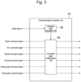
- the command value correction unit 23 includes a correction value calculation unit 35 and a correction value multiplication unit 36.
- the correction value calculation unit 35 outputs a command correction value to correct the command signals output from the operation levers 22.
- the command correction value is determined based on the delay state Ls, which is the output result of the delay state determination unit 26, in accordance with the graph (calculation table) shown in Fig. 4 .
- the correction value multiplication unit 36 multiplies all of the command signals output from the operation levers 22 being operated (i.e., all the command signals of the plurality of actuators 31 being operated with the operation levers 22) by the command correction value calculated by the correction value calculation unit 35 for (uniform) correction.
- This operation uniformly corrects all command signals in the operator-side remote controller 20 (i.e., before the command signals output from the operation levers 22 are transmitted from the operator-side remote controller 20 to the work-machine side remote controller 21), which keeps the ratio of the multiple operation-lever displacements input to the operation levers 22 by the operator.
- the command information transmitter/receiver 24 transmits the (corrected) command signals output from the correction value multiplication unit 36 of the command value correction unit 23 to the command information transmitter/receiver 27 of the work-machine side remote controller 21 via the communication network 34.
- the command information transmitter/receiver 27 of the work-machine side remote controller 21 then transmits the command signals received from the command information transmitter/receiver 24 of the operator-side remote controller 20 via the communication network 34 to the controller 29 of the hydraulic excavator 1.
- the controller 29 controls the operation (state) of the plurality of actuators 31 according to the method described above.
- the actuators 31 boost 8, arm 9, bucket 10, left and right driving motors 11, and turning motor 12
- the actuators 31 will not operate in response to the operation by the operator with the operation levers 22.
- the operator who observes the movement of the work machine displayed on the monitor 33 may recognize that the actuators 31 are not moving as intended, and may increase the displacement of the operation levers 22 (that is, the command signal).
- the actual speed of the actuators 31 becomes faster than the speed of the actuators 31 aimed at by the operator, resulting in an overshoot.
- the boom raising speed the boom will rise too high and the operator fails to excavate earth and sand as intended, resulting in poor efficiency.
- an overshoot occurs for the arm crowding speed, this causes excessive arm crowding to excavate too much, leading to deterioration of efficiency if corrective work is required.
- Patent Literature 1 acts to correct a command signal only for boom raising. In this case, the boom will not rise, and the work machine excavates too much, leading to deterioration of efficiency.
- the present embodiment allows (uniform) multiplication of all of the command signals for boom raising, arm crowding, and bucket crowding by the command correction value according to the delay state, and thus allows the command signals to keep the operation balance as intended by the operator according to the delay state and suppresses the overshoot of the actual speed of the actuators 31 of the work machine compared with the speed of the actuators 31 that the operator intends, making it easier for the work machine to perform the operator's intended motion.
- a communication delay occurs in remote control of the work machine with the plurality of actuators 31, this configuration prevents deterioration of efficiency.
- the first embodiment includes: the operation levers 22 for the operator to operate the plurality of actuators 31 of the work machine; the operator-side remote controller 20 that transmits command signals for operating the plurality of actuators 31 via the communication network 34, the command signals being generated in response to the operation with the operation levers 22; the operator-side remote controller 21 that receives the command signals via the communication network 34 and transmits the command signals to the work machine; the delay state determination unit (delay state determination device) 26 that determines a communication delay state of the command signals that the work-machine side remote controller 21 receives relative to the command signals transmitted from the operator-side remote controller 20; and the command signal correction unit (command signal correction device) 23 that, when it is determined that the communication delay state is worse than a preset delay state determination threshold, corrects all the command signals of the plurality of actuators 31 being operated so as to maintain their ratio.
- the delay state determination unit delay state determination device
- the command signal correction unit (command signal correction device) 23 corrects all the command signals of the plurality of actuators 31 being operated so that the operating speed of the plurality of actuators 31 becomes slower as the communication delay state worsens.
- the command signal correction unit (command signal correction device) 23 determines that communication is disrupted and corrects all the command signals of the plurality of actuators 31 being operated so that the plurality of actuators 31 will not operate.
- the first embodiment limits a plurality of command speeds so as not to cause off-balance of the operating speeds of the actuators 31 being operated.
- the method for limiting a command speed so as not to cause off-balance of the operator's intended operation speed is uniformly correcting all of the operation signals in the operator-side remote controller 20 so as to keep the ratio of the plurality of operation lever displacements input by the operator with the operation levers 22.
- a remote control system for a work machine having a plurality of actuators 31 corrects all command signals for the actuators 31 being operated when a communication delay time occurs during operation with the actuators 31. This limits the operation of the actuators 31 while keeping the ratio of the command signals (operation signals) of the actuators 31, and thus keeps the operating balance of the actuators 31 that the operator intends and facilitates the operation. Limiting the command signals in this way reduces the deviation between the operating state of the work machine that the operator can understand on the monitor 33 and the actual operating state of the work machine, so that the operator is able to input accurate feedback to the operation levers 22 based on the visual result on the work machine displayed on the monitor 33 for efficient work.
- the delay state determination unit (delay state determination device) 26 and the command signal correction unit (command signal correction device) 23 are provided in the operator-side remote controller 20, and the command signal correction unit (command signal correction device) 23 corrects all the command signals for the plurality of actuators 31 being operated before the command signals are transmitted from the operator-side remote controller 20 to the work-machine side remote controller 21.
- the first embodiment enables correction with consideration given to a delay of a command signal that the operator-side remote controller 20, which is a wireless remote controller, transmits to the work-machine side remote controller 21 (via the communication network 34).
- One operator-side remote controller 20 may control the operation of a plurality of hydraulic excavators 1 while switching them. In this case, the number of components of each hydraulic excavator 1 (i.e., of the work-machine side remote controller 21) can be reduced, so that this embodiment reduces the cost as compared with a second embodiment described later, for example.
- the delay state determination unit 26 may determine a communication delay state as follows: the communication state determination units 25 and 28 monitor the transmission time when the operator-side remote controller 20 transmits a command signal and the reception time when the work-machine side remote controller 21 receives the command signal, and the delay state determination unit 26 outputs a communication delay based on the two results.
- the correction value calculation unit 35 of the command value correction unit 23 outputs a command correction value to correct the command signals output from the operation levers 22.
- the command correction value is determined based on the delay time Lt, which is the output result of the delay state determination unit 26, in accordance with the graph (calculation table) shown in Fig. 5 .
- the correction value multiplication unit 36 of the command correction unit 23 multiplies all of the command signals output from the operation levers 22 being operated (i.e., all the command signals of the plurality of actuators 31 being operated with the operation levers 22) by the command correction value calculated by the correction value calculation unit 35 for (uniform) correction.
- This operation uniformly corrects all command signals in the operator-side remote controller 20 (i.e., before the command signals output from the operation levers 22 are transmitted from the operator-side remote controller 20 to the work-machine side remote controller 21), which keeps the ratio of the multiple operation-lever displacements input to the operation levers 22 by the operator.
- the communication is determined disrupted.
- the actuators 31 boost 8, arm 9, bucket 10, left and right driving motors 11, and turning motor 12
- the actuators 31 will not operate in response to the operation by the operator with the operation levers 22.
- the relationship between the delay state Ls and the command correction value used in the command value correction unit 23 (correction value calculation unit 35 thereof) may be set as shown in Fig. 6 .
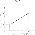
- the threshold LsX of the delay state Ls (the threshold to determine whether correction is required or not, hereinafter also referred to as the correction state threshold), from which the command correction value starts to decrease from 1.0, is determined based on the graph (calculation table) in Fig. 7.
- Fig. 7 shows the relationship between the largest operation command signal (hereinafter referred to as maximum operation command signal) for the command signals of the actuators 31 being operated in the work machine and the correction state threshold LsX. According to the graph in Fig.
- the smaller the maximum operation command signal the smaller the correction state threshold LsX from which the command correction value starts to fall from 1.0.
- the maximum operation command signal is small, that is, when the operating speed of the actuators 31 of the work machine is slow, the deviation per unit time caused by the communication delay between the operation amount of the actuators 31 of the work machine and the operation amount of the actuators 31 of the work machine intended by the operator is small. That is, when the operating speed of the actuators 31 is small, a small correction state threshold LsX, from which the command correction value starts to decrease, is set. This means that the command signals are not corrected until the communication is largely delayed.
- the correction state threshold (delay state determination threshold) LsX of the delay state Ls from which the command correction value starts to decrease from 1.0 can be set according to the operating speed of the plurality of actuators 31 of the work machine. This enhances the stability of the work machine and efficiently improves the operability.
- the delay state determination unit 26 may determine a communication delay state as follows: the communication state determination units 25 and 28 monitor the transmission time when the operator-side remote controller 20 transmits a command signal and the reception time when the work-machine side remote controller 21 receives the command signal, and the delay state determination unit 26 outputs a communication delay state based on the two results.
- the correction time threshold (delay state determination threshold) LtX of the delay time Lt from which the command correction value starts to decrease from 1.0 is set depending on the operating speed of multiple actuators 31 of the work machine.
- the relationship between the delay time Lt and the command correction value is as shown in Fig. 8
- the relationship between the maximum operation command signal and the correction state threshold LtX is as shown in Fig. 9 .
- Fig. 10 is a block diagram of the structure of a remote control system for hydraulic excavator that is one example of the work machine according to a second embodiment.
- the operator-side remote controller 20 includes the delay state determination unit 26 that determines the communication delay state between the operator-side remote controller 20 and the work-machine side remote controller 21, and the command signal correction unit 23 that corrects command signals generated in response to the operation with the operation levers 22 based on the output from the delay state determination unit 26.
- the delay state determination unit 26 determines the communication delay state between the operator-side remote controller 20 and the work-machine side remote controller 21
- the command signal correction unit 23 that corrects command signals generated in response to the operation with the operation levers 22 based on the output from the delay state determination unit 26.
- a work-machine side remote controller 21 includes a delay state determination unit (delay state determination device) 37 and a command signal correction unit (command signal correction device) 38.
- the delay state determination unit 37 functions in the same manner as the delay state determination unit 26 described in the first embodiment. Note that the delay state determination unit 37 receives signals from the communication state determination unit 25 of the operator-side remote controller 20 via the communication network 34, and directly receives signals from the communication state determination unit 28 of the work-machine side remote controller 21 within the device.
- the delay state determination unit 37 determines the communication delay state with the operator-side remote controller 20 based on the outputs of the communication state determination unit 25 of the operator-side remote controller 20 and of the communication state determination unit 28 of the work-machine side remote controller 21. Specifically, the delay state determination unit 37 determines the communication delay state of the command signal that the command information transmitter/receiver 27 of the work-machine side remote controller 21 receives relative to the command signal transmitted from the command information transmitter/receiver 24 of the operator-side remote controller 20, based on the outputs of the communication state determination unit 25 of the operator-side remote controller 20 and of the communication state determination unit 28 of the work-machine side remote controller 21.
- the specific method of determining the communication state by the delay state determination unit 37 is the same as in the first embodiment.
- the command value correction unit 38 has the same configuration as the command signal correction unit 23 (including the correction value calculation unit 35 and the correction value multiplication unit 36) shown in Fig. 3 .
- the correction value calculation unit 35 outputs a command correction value to correct the command signals output from the operation levers 22.
- the command correction value is determined based on the delay state Ls, which is the output result of the delay state determination unit 37, in accordance with the graph (calculation table) shown in Fig. 4 .
- the correction value multiplication unit 36 multiplies all of the command signals output from the operation levers 22 being operated and received from the operator-side remote controller 20 (the command information transmitter/receiver 24 thereof) via the communication network 34 (i.e., all the command signals of the plurality of actuators 31 being operated with the operation levers 22) by the command correction value calculated by the correction value calculation unit 35 for (uniform) correction.
- the correction value multiplication unit 36 transmits the (corrected) command signals as the output result to the controller 29 of the hydraulic excavator 1.
- the second embodiment also limits a plurality of command speeds so as not to cause off-balance of the operating speeds of the actuators 31 being operated.
- the method for limiting a command speed so as not to cause off-balance of the operator's intended operation speed is uniformly correcting all of the operation signals in the work-machine side remote controller 21 so as to keep the ratio of the plurality of operation lever displacements input by the operator with the operation levers 22. This embodiment therefore leads to the same advantageous effects as those described in the first embodiment.
- the delay state determination unit (delay state determination device) 37 and the command signal correction unit (command signal correction device) 38 are provided in the work-machine side remote controller 21, and the command signal correction unit (command signal correction device) 38 corrects all the command signals for the plurality of actuators 31 being operated before the command signals are transmitted from the work-machine side remote controller 21 to the work machine (controller 29 thereof).
- the correction information (corrected command signals) is transmitted to the controller 29 of the hydraulic excavator (work machine) 1 without going through the communication network 34.
- This allows the correction to be immediately reflected in the operation of the actuators 31.
- one hydraulic excavator 1 may be operated while switching a plurality of operator-side remote controllers 20.
- the number of components of each operator-side remote controller 20 as the wireless remote controllers can be reduced, so that this embodiment reduces the cost as compared with the first embodiment described above, for example.
- the second embodiment can include the contents described above based on Figs. 5 through 9 in addition to Fig. 4 .
- Fig. 11 is a block diagram of the structure of a command value correction unit in a remote control system for hydraulic excavator that is one example of the work machine according to a third embodiment.
- the third embodiment will be described as a modification of the command value correction unit 23 of the operator-side remote controller 20 in the first embodiment. Needless to say, the configuration is applicable to the command value correction unit 38 of the work-machine side remote controller 21 in the second embodiment.
- the configuration of the command value correction unit 23 in the first embodiment (or the command value correction unit 38 in the second embodiment) is as shown in Fig. 11 .
- the command value correction unit 23 functions as a correction calculation unit that calculates a command correction value to correct command signals output from the operation levers 22 based on the delay state Ls as the output result of the delay state determination unit 26, and outputs the command correction value.
- the command value correction unit 23 includes: a correction value A calculation unit 39, which calculates a command correction value A for correcting the command signals of the boom 8, arm 9, and bucket 10 (boom command signal, arm command signal, and bucket command signal) based on the delay state Ls; a correction value B calculation unit 40, which calculates a command correction value B for correcting the command signal of the turning motor 12 (turning command signal) based on the delay state Ls; and a correction value C calculation unit 41, which calculates a command correction value C for correcting the command signals of the right driving motor 11 and the left driving motor 11 (driving-right command signal and driving-left command signal) based on the delay state Ls.
- a correction value A calculation unit 39 which calculates a command correction value A for correcting the command signals of the boom 8, arm 9, and bucket 10 (boom command signal, arm command signal, and bucket command signal) based on the delay state Ls
- a correction value B calculation unit 40 which calculates a command correction value B for correcting the command signal of the
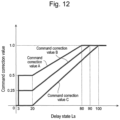
- the correction value A calculation unit 39, the correction value B calculation unit 40, and the correction value C calculation unit 41 calculate the command correction value A, the command correction value B, and the command correction value C, respectively, based on the delay state Ls in accordance with the calculation table as shown in Fig. 12 (details will be explained later).
- a correction value A multiplication unit 42 multiplies the command signals of the boom 8, arm 9, and bucket 10 (boom command signal, arm command signal, and bucket command signal) by the command correction value A calculated by the correction value A calculation unit 39.
- a correction value B multiplication unit 43 multiplies the command signal of the turning motor 12 (turning command signal) by the command correction value B calculated by the correction value B calculation unit 40.
- a correction value C multiplication unit 44 multiplies the command signals of the right driving motor 11 and the left driving motor 11 (driving-right command signal and driving-left command signal) by the command correction value C calculated by the correction value C calculation unit 41.
- correction value A calculation unit 39, the correction value B calculation unit 40, and the correction value C calculation unit 41 calculate the command correction value A, the command correction value B, and the command correction value C, respectively, based on the graph (calculation table) shown in Fig. 12 , they can change the command correction value for each of the actuators 31 depending on the communication delay state Ls.
- the graph of Fig. 12 shows the command correction value A, command correction value B, and command correction value C calculated based on the delay state Ls.
- the command correction value of 1.0 is output for the command correction value A, which means that the command signals are not corrected.
- the command correction value B decreases gradually.
- the correction value A multiplication unit 42, the correction value B multiplication unit 43, and the correction value C multiplication unit 44 multiply all the command signals output from the operation levers 22 being operated (i.e., all the command signals of the plurality of actuators 31 being operated via the operation levers 22) by the command correction value A, the command correction value B, and the command correction value C calculated by the correction value A calculation unit 39, the correction value B calculation unit 40, and the correction value C calculation unit 41 for correction, that is, correct the command signal for each of the plurality of actuators 31 being operated via the operation levers 22.
- the system of this embodiment changes the degree of limitation (deceleration) for the specific actuator 31.
- this embodiment changes the command correction value based on the delay state depending on the actuators 31, which changes the behavior of the operation restriction of each actuator 31 according to the communication state.
- the command correction value A, the command correction value B, and the command correction value C are set to 0.5, 0.25, and 0, respectively, meaning that the boom 8, the arm 9 and the bucket 10 operate with half the operation command, and the turning motor 12 operates with the 1/4 operation command.
- the command signal is multiplied by zero, meaning that these motors will not operate in response to the operation by the operator with the operation levers 22.
- this configuration sets some actuators 31 to slow down the operation and other actuators 31 that do not operate (or extremely slow down). This reduces the possibility that the work machine falls into a dangerous state when the communication state is poor while keeping the work efficiency without stopping some works that do not become a dangerous state.
- the command signal correction unit (command signal correction device) 23 corrects the command signal for each of the plurality of actuators 31 being operated.
- the command signal correction unit (command signal correction device) 23 is configured so that the delay state determination threshold and a command correction value in accordance with the communication delay state to correct the command signal are set for each of the plurality of actuators 31.
- the third embodiment limits a plurality of command speeds so as not to cause off-balance of the operating speeds of the actuators 31 being operated.
- this embodiment gives priority to limiting the speed of a specific actuator 31 rather than keeping the operating speed balance of the actuators 31 being operated, for example, to prevent the falling of the hydraulic excavator 1 during traveling.
- the method for limiting a command speed so as not to cause off-balance of the operator's intended operation speed is, when the communication delay time exceeds a certain threshold, changing the way of applying limitations for a specific actuator 31.
- a remote control system for a work machine having a plurality of actuators 31 corrects all command signals for the actuators 31 being operated when a communication delay time occurs during operation with the actuators 31. This limits the operation of the actuators 31 while keeping the ratio of the command signals (operation signals) of the actuators 31, and thus keeps the operating balance of the actuators 31 that the operator intends and facilitates the operation. Limiting the command signals in this way reduces the deviation between the operating state of the work machine that the operator can understand on the monitor 33 and the actual operating state of the work machine, so that the operator is able to input accurate feedback to the operation levers 22 based on the visual result on the work machine displayed on the monitor 33 for efficient work.
- the system changes the degree of limitation for a specific actuator 31, which prevents the falling of the hydraulic excavator 1 during traveling, for example.
- the delay state determination unit 26 may determine a communication delay state as follows: the communication state determination units 25 and 28 monitor the transmission time when the operator-side remote controller 20 transmits a command signal and the reception time when the work-machine side remote controller 21 receives the command signal, and the delay state determination unit 26 determines the communication delay state using the communication delay time Lt output based the two results.
- the correction value A calculation unit 39, the correction value B calculation unit 40, and the correction value C calculation unit 41 of the command value correction unit 23 calculate the command correction value A, the command correction value B, and the command correction value C, respectively, based on the graph (calculation table) shown in Fig. 13 based on the delay time Lt.
- the command correction value A shows the command correction value A, command correction value B, and command correction value C calculated based on the delay time Lt.
- the command correction value of 1.0 is output for the command correction value A, which means that the command signals are not corrected.
- the command correction value B decreases gradually.
- the correction value A multiplication unit 42, the correction value B multiplication unit 43, and the correction value C multiplication unit 44 of the command correction unit 23 multiply all the command signals output from the operation levers 22 being operated (i.e., all the command signals of the plurality of actuators 31 being operated via the operation levers 22) by the command correction value A, the command correction value B, and the command correction value C calculated by the correction value A calculation unit 39, the correction value B calculation unit 40, and the correction value C calculation unit 41 for correction, that is, correct the command signal for each of the plurality of actuators 31 being operated via the operation levers 22.
- the system of this embodiment changes the degree of limitation (deceleration) for the specific actuator 31.
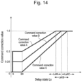
- the relationship between the delay state Ls and the command correction value used in the command value correction unit 23 may be set as shown in Fig. 14 .
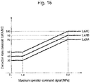
- the thresholds LsXA, LsXB, and LsXC of the delay state Ls (the threshold to determine whether correction is required or not, hereinafter also referred to as the correction state thresholds), from which the command correction values A, B, and C start to decrease from 1.0, are determined based on the graph (calculation table) in Fig. 15.
- the larger the maximum operation command signal the larger the correction state thresholds LsXA, LsXB, and LsXC, from which the command correction value starts to fall from 1.0
- the smaller the maximum operation command signal the smaller the correction state thresholds LsXA, LsXB, and LsXC, from which the command correction value starts to fall from 1.0.
- the smaller the maximum operation command signal the smaller the correction state thresholds LsXA, LsXB, and LsXC, from which the command correction value starts to fall from 1.0.
- the maximum operation command signal is small, that is, when the operating speed of the actuators 31 of the work machine is slow, the deviation per unit time caused by the communication delay between the operation amount of the actuators 31 of the work machine and the operation amount of the actuators 31 of the work machine intended by the operator is small. That is, when the operating speed of the actuators 31 is small, small correction state thresholds LsXA, LsXB, and LsXC, from which the command correction value starts to decrease, are set.
- the correction state thresholds (delay state determination thresholds ) LsXA, LsXB, and LsXC of the delay state Ls from which the command correction values A, B, and C start to decrease from 1.0 can be set according to the operating speeds of the plurality of actuators 31 of the work machine. This enhances the stability of the work machine and efficiently improves the operability.
- the delay state determination unit 26 may determine a communication state as follows: the communication state determination units 25 and 28 monitor the transmission time when the operator-side remote controller 20 transmits a command signal and the reception time when the work-machine side remote controller 21 receives the command signal, and the delay state determination unit 26 outputs a communication delay state based on the two results.
- the correction time thresholds LsXA, LsXB, LsXC of the delay time Lt from which the command correction values A, B, and C start to decrease from 1.0 are set depending on the operating speed of multiple actuators 31 of the work machine.
- the present invention is not limited to these embodiments, and may include various modifications.
- the entire detailed configuration of the embodiments described above for explanatory convenience is not always necessary for the present invention.
- a part or all of the functions that the controllers of the above-described embodiments have may be designed as an integrated circuit and may be implemented as hardware.
- the processor may interpret and execute a program that implements each function, thereby implementing the functions as software.
- Programs for implementing these functions, and information such as tables, and files can be stored in a storage device in the controller, a recording device such as a hard disk or SSD (Solid State Drive), or a recording medium such as an IC card, SD card, or DVD.
Landscapes
- Engineering & Computer Science (AREA)
- Mining & Mineral Resources (AREA)
- Structural Engineering (AREA)
- General Engineering & Computer Science (AREA)
- Civil Engineering (AREA)
- Physics & Mathematics (AREA)
- General Physics & Mathematics (AREA)
- Automation & Control Theory (AREA)
- Computer Networks & Wireless Communication (AREA)
- Remote Sensing (AREA)
- Radar, Positioning & Navigation (AREA)
- Aviation & Aerospace Engineering (AREA)
- Signal Processing (AREA)
- Mechanical Engineering (AREA)
- Mathematical Physics (AREA)
- Theoretical Computer Science (AREA)
- Computing Systems (AREA)
- Operation Control Of Excavators (AREA)
- Selective Calling Equipment (AREA)
- Telephonic Communication Services (AREA)
Abstract
Description
- The present invention relates to a remote control system for work machine having a plurality of actuators.
- With the recent spread of the Internet and the faster communication speed, efforts are being made to build remote control systems in various fields such as automobiles, drones, robots, and work machines for remote control via communication networks.
- Among them, a work machine is remotely controlled as follows: a camera mounted on the work machine, which is the target device to be controlled, is used to capture an image of the target device and its surroundings, and the captured image is transmitted from the target device to a remote controller. An operator then monitors the image displayed on the remote controller for operation, and transmits the operated control signal from the remote controller to the target device to remotely control the target device. When the target device is used outdoors, a wireless communication network is often used between the target device and the communication network.
- In the wireless communication network, however, data packet loss, a communication delay, and communication speed fluctuations may occur due to changes in received signal quality and communication line congestion. In this case, the stability or the operability of a remote control system for real-time control may deteriorate. For example, when the operator wants a front unit of a hydraulic excavator to move along the desired trajectory, a large communication delay in the wireless communication network, if any, may delay the image displayed on the monitor. In that case, the operator will not be able to accurately understand the actual state of the front unit. This makes it difficult to move the front unit accurately in real time, which may reduce the work efficiency. Studies have been made to enable stable remote control even when a communication delay or fluctuations in communication speed occur between the remote controller and the target device.
-
Patent Literature 1 describes a technique of solving the communication delay of a remote control system. This conventional technology describes a remote controller that remotely controls a target device via a communication network. The remove controller calculates the amount of overshoot, which may occur due to the communication delay time, from the communication delay time and the operating speed of the target device, and limits the operating speed so that the overshoot amount is less than a preset threshold. - Patent Literature 1:
JP 2018-107568 A - When the technique described in
Patent Literature 1 is applied to a work machine that needs to operate a plurality of actuators at the same time, the overshoot amount due to the communication delay is calculated and the threshold is set for each of the actuators. This means that if only one of the actuators has to be limited in the operating speed in a certain communication delay state, then only the specific actuator is decelerated, which causes off-balance in the combined operation of the work machine. That is, in the case of remote control of a plurality of actuators of a work machine, if an overshoot only for a specific actuator occurs due to a communication delay, the work machine will inefficiently operate in an unintended manner of the operator. - For example, assume that the work machine is performing excavation work with the boom, the arm, and the bucket. If an overshoot of the actual speed occurs only for the arm speed relative to the speed intended by the operator due to a communication delay time, only the commanded speed of the arm is limited so that the overshoot amount of the arm speed is less than a predetermined value. In this case, assuming that no overshoot due to the communication delay time occurs for the boom and the bucket, the commanded speeds of the boom and the bucket are not limited. As a result, only the arm speed is limited relative to the intended speed of the operator, which makes it impossible to operate the work machine as the operator intends, and worsens the operability.
- Further, the remote control has a general problem: when the communication delay time becomes large, the difference between the state of the work machine viewed by the operator through the communication network with the camera and the state of the actual work machine becomes large. Therefore, the work machine may operate in a significantly different manner from the intention of the operator.
- In view of the above problems, the present invention provides a remote control system for work machine capable of enhancing the stability and efficiently improving the operability.
- To solve the above problems, a remote control system for a work machine according to the present invention includes: an operation lever to let an operator operate a plurality of actuators of the work machine; an operator-side remote controller configured to transmit command signals for operating the plurality of actuators via a communication network, the command signals being generated in response to operation with the operation lever; a work-machine side remote controller configured to receive the command signals via the communication network and transmit the command signals to the work machine; a delay state determination device configured to determine a communication delay state of the command signals that the work-machine side remote controller receives relative to the command signals transmitted from the operator-side remote controller; and a command signal correction device configured to, when it is determined that the communication delay state is worse than a preset delay state determination threshold, correct all the command signals of the plurality of actuators being operated so as to maintain a ratio among the command signals.
- According to the present invention, a remote control system for a work machine having a plurality of actuators corrects all command signals for the actuators being operated when a communication delay time occurs during operation with the actuators. This limits the operation of the actuators while keeping the ratio of the command signals (operation signals) of the actuators, and thus keeps the operating balance of the actuators that the operator intends and facilitates the operation. Limiting the command signals in this way reduces the deviation between the operating state of the work machine that the operator can understand on the monitor and the actual operating state of the work machine, so that the operator is able to input accurate feedback to the operation levers based on the visual result on the work machine displayed on the monitor for efficient work.
- Other problems, configurations and advantageous effects also will be clear from the following descriptions of the embodiments.
-
-
Fig. 1 schematically shows the structure of a remote control system for hydraulic excavator that is one example of the work machine according to a first embodiment. -
Fig. 2 is a block diagram of the structure of the remote control system for hydraulic excavator that is one example of the work machine according to the first embodiment. -
Fig. 3 is a block diagram of the structure of a command signal correction unit according to the first embodiment. -
Fig. 4 shows a calculation table of a command value calculation unit based on a delay state according to the first and second embodiments. -
Fig. 5 shows a calculation table of the command value calculation unit based on a delay time according to the first and second embodiments. -
Fig. 6 shows a modified example of the calculation table of the command value calculation unit based on a delay state according to the first and second embodiments. -
Fig. 7 shows a calculation table of the correction state threshold based on the maximum operation command signal according to the first and second embodiments. -
Fig. 8 shows a modified example of the calculation table of the command value calculation unit based on a delay time according to the first and second embodiments. -
Fig. 9 shows a calculation table of the correction time threshold based on the maximum operation command signal according to the first and second embodiments. -
Fig. 10 is a block diagram of the structure of a remote control system for hydraulic excavator that is one example of the work machine according to a second embodiment. -
Fig. 11 is a block diagram of the structure of a command signal correction unit according to a third embodiment. -
Fig. 12 shows a calculation table of a command value calculation unit based on a delay state according to the third embodiment. -
Fig. 13 shows a calculation table of the command value calculation unit based on a delay time according to the third embodiment. -
Fig. 14 shows a modified example of the calculation table of the command value calculation unit based on a delay state according to the third embodiment. -
Fig. 15 shows a calculation table of the correction state threshold based on the maximum operation command signal according to the third embodiment. -
Fig. 16 shows a modified example of the calculation table of the command value calculation unit based on a delay time according to the third embodiment. -
Fig. 17 shows a calculation table of the correction time threshold based on the maximum operation command signal according to the third embodiment. - The following describes some embodiments of the present invention, with reference to the attached drawings. In the attached drawings, like numbers indicate like components having the same functions to omit their duplicated descriptions. This embodiment exemplifies a work machine by way of a hydraulic excavator. The work machine is not limited to a hydraulic excavator, and is applicable to construction machines such as wheel loaders, cranes, bulldozers, dumps, and road machines, and general work machines other than construction machines, as long as the operator can operate a plurality of actuators of the work machine by remote control.
-
Figs. 1 and2 show a remote control system for hydraulic excavator that is one example of the work machine according to a first embodiment, whereFig. 1 schematically shows the structure, andFig. 2 is a block diagram of the structure. - As shown in
Fig. 1 , the hydraulic excavator (work machine) 1 includes a crawler-type lower travelingbody 2, an upper turningbody 3 mounted to be able to turn relative to thelower traveling body 2, and afront unit 7 attached to the front of the upper turningbody 3 to be able to move up and down and perform works such as excavation. - The lower traveling
body 2 includes a pair of left and right driving motors 11 (hereinafter, they may be referred to as aright driving motor 11 and a left driving motor 11). The upper turningbody 3 includes a prime mover such as an engine, a hydraulic pump, and aturning motor 12. Thefront unit 7 has aboom 8, anarm 9, and abucket 10, which are driven by a boom cylinder, an arm cylinder, and a bucket cylinder, respectively, that are hydraulic cylinders driven by hydraulic oil. Theboom 8, thearm 9, thebucket 10, the turningmotor 12, and the drivingmotor 11 constituteactuators 31 of the work machine of the present embodiment (seeFig. 2 ). - The
hydraulic excavator 1 includes a work-machine sideremote controller 21 provided with units such as a command information transmitter/receiver 27 for transmitting/receiving command information (command signal). An operator-side remote controller (this may be called a wireless remote controller) 20 is provided outside thehydraulic excavator 1, for example in the control room, and this operator-sideremote controller 20 includes a command information transmitter/receiver 24 for transmitting/receiving command information (command signal). The remote control system of the present embodiment is wireless communicable of (transmitting and receiving) information and signals between the operator-side remote controller 20 (the command information transmitter/receiver 24 thereof) and the work-machine side remote controller 21 (the command information transmitter/receiver 27 thereof) via acommunication network 34. - The operator-side
remote controller 20 of the present embodiment includes a plurality of remote-control operation levers (hereinafter, simply referred to as operation levers) 22 to let the operator operate each of the plurality of actuators 31 (boom 8,arm 9,bucket 10, left and right drivingmotors 11, and turning motor 12). In response to the operation of these operation levers 22 by the operator, a command signal corresponding to the operation of each operation lever 22 (displacement of the operation lever) is generated to operate the actuator 31 (boom 8,arm 9,bucket 10, left and right drivingmotors 11, or turning motor 12) corresponding to theoperation lever 22, and is output to the command information transmitter/receiver 24. - As shown in
Fig. 2 , thehydraulic excavator 1 has a basic configuration including: a plurality ofsolenoid valves 30 that generate hydraulic signals for operating the plurality ofactuators 31; and acontroller 29 that controls the operation (status) of the plurality ofactuators 31. To this end, thecontroller 29 converts a command signal input from the outside (in this case, the command information transmitter/receiver 27 of the work-machine side remote controller 21) into a current for a command to thesolenoid valves 30. - The following describes the embodiment of applying the remote control system of the present embodiment to a typical
hydraulic excavator 1 having an electric lever system that is configured so that a command signal generated in response to the operation with the operation levers 22 in the operation room as shown inFigs. 1 and2 is sent to thesolenoid valves 30 via thecontroller 29, and the actuators 31 (boom 8,arm 9,bucket 10, left and right drivingmotors 11, and turning motor 12) are operated based on the hydraulic pressure from thesolenoid valves 30 via a control valve. - A detailed description on the configuration of such a typical
hydraulic excavator 1 is omitted here. - As shown in the drawing, the operation levers 22 and the operator-side
remote controller 20 may be configured as one device (in other words, the operator-sideremote controller 20 includes the operation levers 22), or they may configured as separate devices. As shown in the drawing, the hydraulic excavator (work machine) 1 and the work-machine sideremote controller 21 may be configured as separate devices, or may be configured as one device (in other words, thehydraulic excavator 1 internally includes the work-machine side remote controller 21). - Although not shown, the operator-side
remote controller 20 and the work-machine sideremote controller 21 described above are configured as a microcomputer that includes a central processing unit (CPU) that performs various calculations, a memory such as a read only memory (ROM) or a hard disk drive (HDD) that stores programs for executing calculations by the CPU, and a random access memory (RAM) that is a work area where the CPU executes programs. Various functions of the operator-sideremote controller 20 and the work-machine sideremote controller 21 are implemented by the CPU loading various programs stored in the memory into the RAM for execution. - The operator operates the actuators 31 (
boom 8,arm 9,bucket 10, left and right drivingmotors 11, and turning motor 12) of the work machine with the operation levers 22 in the operator-sideremote controller 20 shown inFig. 2 . - Specifically, a
monitor 33 displays the video of the operating state of the hydraulic excavator 1 (actuators 31) taken by acamera 32 from the outside, for example, in the control room, via thecommunication network 34. Then, the operator operates the operation levers 22 in the operator-sideremote controller 20 while viewing the video on themonitor 33 for remote control of theactuators 31 of the work machine. That is, thecamera 32 is an operation state confirmation device for confirming the operation state of the hydraulic excavator 1 (actuators 31) from the outside, and themonitor 33 is an operation state display device that receives the output (video) of the camera (operation state confirmation device) 32 via thecommunication network 34 to let the operator view the video. - As shown in
Fig. 2 , the operator-sideremote controller 20 includes: a command signal correction unit (command signal correction device) 23 that corrects command signals generated in response to the operation of the operation levers 22 based on the output of a delay state determination unit (delay state determination device) 26; a command information transmitter/receiver 24 that transmits command information (specifically, command signals output from the command signal correction unit 23) via thecommunication network 34; a communicationstate determination unit 25 that determines the communication state of the operator-sideremote controller 20; and the delaystate determination unit 26 that determines a communication delay state (hereinafter this may be simply referred to as a delay state) with the work-machine sideremote controller 21 based on the output of a communicationstate determination unit 28 that determines the communication state of the work-machine sideremote controller 21 and the output of the communicationstate determination unit 25 that determines the communication state of the operator-sideremote controller 20. - The work-machine side
remote controller 21 of thehydraulic excavator 1 includes: a command information transmitter/receiver 27 that receives command information (command signals) from the operator-side remote controller 20 (command information transmitter/receiver 24 thereof) via thecommunication network 34 and transmits the command signals to thecontroller 29 of thehydraulic excavator 1; and the communicationstate determination unit 28 that determines a communication state of the work-machine sideremote controller 21. - As described above, the delay
state determination unit 26 determines the communication delay state with the work-machine sideremote controller 21 based on the outputs of the communicationstate determination unit 25 of the operator-sideremote controller 20 and of the communicationstate determination unit 28 of the work-machine sideremote controller 21. Specifically, the delaystate determination unit 26 determines the communication delay state of the command signal that the command information transmitter/receiver 27 of the work-machine sideremote controller 21 receives relative to the command signal transmitted from the command information transmitter/receiver 24 of the operator-sideremote controller 20, based on the outputs of the communicationstate determination unit 25 of the operator-sideremote controller 20 and of the communicationstate determination unit 28 of the work-machine sideremote controller 21. - Specifically, the delay
state determination unit 26 determines the communication delay state as follows: the communicationstate determination units state determination unit 26 outputs an overall communication delay state based on the two results. - Assume that the radio wave strength of the operator-side remote controller 20 (monitored by the communication state determination unit 25) is α and the radio wave strength of the work-machine side remote controller 21 (monitored by the communication state determination unit 28) is β. Then, the delay
state determination unit 26 calculates the delay state as Ls = α×β. The higher the radio wave strengths α and β, the better the communication condition, and the smaller the radio wave strengths α and β, the worse the communication condition. - As shown in
Fig. 3 , the commandvalue correction unit 23 includes a correctionvalue calculation unit 35 and a correctionvalue multiplication unit 36. The correctionvalue calculation unit 35 outputs a command correction value to correct the command signals output from the operation levers 22. The command correction value is determined based on the delay state Ls, which is the output result of the delaystate determination unit 26, in accordance with the graph (calculation table) shown inFig. 4 . The graph ofFig. 4 shows the command correction value calculated based on the delay state Ls. For example, during the delay state Ls=80 to 100, which is determined a good communication state, the command correction value of 1.0 is output, which means that the command signals are not corrected. During the delay state Ls=20 to 80, as the delay state Ls decreases (that is, the communication state worsens), the command correction value decreases gradually from 1.0 to 0. 5 (proportionately in this example). That is, Ls=80 is set as the threshold to determine whether the correction is necessary or not based on the delay state Ls output from the delaystate determination unit 26. If the delaystate determination unit 26 outputs the delay state Ls that is smaller (that is, worsening) than the delay state determination threshold Ls=80, a command correction value less than 1.0 is output for correcting the command signals. Further, when the delay state is less than Ls=3, it is determined that the communication state is extremely bad, and the command correction value for the delay state is immediately lowered to 0. In other words, Ls=3 is set as the threshold to determine whether the communication state is extremely poor and the communication is disrupted. If the delay state Ls output from the delaystate determination unit 26 is smaller (i.e., worsening) than Ls=3 as the communication disruption determination threshold, it is determined that the communication is disrupted. Then the command correction value of 0 is output to correct the command signals so that the plurality ofactuators 31 do not operate. - The correction
value multiplication unit 36 multiplies all of the command signals output from the operation levers 22 being operated (i.e., all the command signals of the plurality ofactuators 31 being operated with the operation levers 22) by the command correction value calculated by the correctionvalue calculation unit 35 for (uniform) correction. This operation uniformly corrects all command signals in the operator-side remote controller 20 (i.e., before the command signals output from the operation levers 22 are transmitted from the operator-sideremote controller 20 to the work-machine side remote controller 21), which keeps the ratio of the multiple operation-lever displacements input to the operation levers 22 by the operator. - The command information transmitter/
receiver 24 transmits the (corrected) command signals output from the correctionvalue multiplication unit 36 of the commandvalue correction unit 23 to the command information transmitter/receiver 27 of the work-machine sideremote controller 21 via thecommunication network 34. The command information transmitter/receiver 27 of the work-machine sideremote controller 21 then transmits the command signals received from the command information transmitter/receiver 24 of the operator-sideremote controller 20 via thecommunication network 34 to thecontroller 29 of thehydraulic excavator 1. Thecontroller 29 controls the operation (state) of the plurality ofactuators 31 according to the method described above. - As a result, during Ls = 80 to 100 where the communication state between the operator-side
remote controller 20 and the work-machine sideremote controller 21 is determined to be in good condition, the operation speed of the actuators 31 (boom 8,arm 9,bucket 10, left and right drivingmotors 11, and turning motor 12) of the work machine is not limited (decelerated), and during Ls = 20 to 80 (i.e., it is determined that the delay state Ls output from the delayeddetermination unit 26 is worse than the delay state determination threshold Ls=80), the operating speed of the actuators 31 (boom 8,arm 9,bucket 10, left and right drivingmotors 11, turning motor 12) of the work machine is (uniformly) limited (decelerated) in accordance with the degree of worsening of the delay state Ls. If the delay state Ls is less than Ls=3 (i.e., it is determined that the delay state Ls output from the delaystate determination unit 26 is worse than Ls=3, which is the threshold for determining communication disruption), the communication is determined disrupted. In this case, the actuators 31 (boom 8,arm 9,bucket 10, left and right drivingmotors 11, and turning motor 12) of the work machine will not operate in response to the operation by the operator with the operation levers 22. - In general, if a communication delay occurs when operating a plurality of
actuators 31, the actual operation of the work machine will be delayed compared with the command signals input by the operator via the operation levers 22. In this case, the operator who observes the movement of the work machine displayed on themonitor 33 may recognize that theactuators 31 are not moving as intended, and may increase the displacement of the operation levers 22 (that is, the command signal). - As a result, the actual speed of the
actuators 31 becomes faster than the speed of theactuators 31 aimed at by the operator, resulting in an overshoot. When the work machine is performing excavation, including boom raising, arm crowding, and bucket crowding operations, if an overshoot occurs for the boom raising speed, the boom will rise too high and the operator fails to excavate earth and sand as intended, resulting in poor efficiency. If an overshoot occurs for the arm crowding speed, this causes excessive arm crowding to excavate too much, leading to deterioration of efficiency if corrective work is required. - For an overshoot of boom raising, the control of
Patent Literature 1 acts to correct a command signal only for boom raising. In this case, the boom will not rise, and the work machine excavates too much, leading to deterioration of efficiency. - In this case, the present embodiment allows (uniform) multiplication of all of the command signals for boom raising, arm crowding, and bucket crowding by the command correction value according to the delay state, and thus allows the command signals to keep the operation balance as intended by the operator according to the delay state and suppresses the overshoot of the actual speed of the
actuators 31 of the work machine compared with the speed of theactuators 31 that the operator intends, making it easier for the work machine to perform the operator's intended motion. As a result, if a communication delay occurs in remote control of the work machine with the plurality ofactuators 31, this configuration prevents deterioration of efficiency. - As described above, the first embodiment includes: the operation levers 22 for the operator to operate the plurality of
actuators 31 of the work machine; the operator-sideremote controller 20 that transmits command signals for operating the plurality ofactuators 31 via thecommunication network 34, the command signals being generated in response to the operation with the operation levers 22; the operator-sideremote controller 21 that receives the command signals via thecommunication network 34 and transmits the command signals to the work machine; the delay state determination unit (delay state determination device) 26 that determines a communication delay state of the command signals that the work-machine sideremote controller 21 receives relative to the command signals transmitted from the operator-sideremote controller 20; and the command signal correction unit (command signal correction device) 23 that, when it is determined that the communication delay state is worse than a preset delay state determination threshold, corrects all the command signals of the plurality ofactuators 31 being operated so as to maintain their ratio. - The command signal correction unit (command signal correction device) 23 corrects all the command signals of the plurality of
actuators 31 being operated so that the operating speed of the plurality ofactuators 31 becomes slower as the communication delay state worsens. - When the communication delay state is determined to be worse than a preset communication disruption determination threshold, the command signal correction unit (command signal correction device) 23 determines that communication is disrupted and corrects all the command signals of the plurality of
actuators 31 being operated so that the plurality ofactuators 31 will not operate. - In other words, when an overshoot of the operating speed of the
actuators 31 occurs due to the communication delay time, the first embodiment limits a plurality of command speeds so as not to cause off-balance of the operating speeds of theactuators 31 being operated. The method for limiting a command speed so as not to cause off-balance of the operator's intended operation speed is uniformly correcting all of the operation signals in the operator-sideremote controller 20 so as to keep the ratio of the plurality of operation lever displacements input by the operator with the operation levers 22. - According to the first embodiment, a remote control system for a work machine having a plurality of
actuators 31 corrects all command signals for theactuators 31 being operated when a communication delay time occurs during operation with theactuators 31. This limits the operation of theactuators 31 while keeping the ratio of the command signals (operation signals) of theactuators 31, and thus keeps the operating balance of theactuators 31 that the operator intends and facilitates the operation. Limiting the command signals in this way reduces the deviation between the operating state of the work machine that the operator can understand on themonitor 33 and the actual operating state of the work machine, so that the operator is able to input accurate feedback to the operation levers 22 based on the visual result on the work machine displayed on themonitor 33 for efficient work. - In the first embodiment, the delay state determination unit (delay state determination device) 26 and the command signal correction unit (command signal correction device) 23 are provided in the operator-side
remote controller 20, and the command signal correction unit (command signal correction device) 23 corrects all the command signals for the plurality ofactuators 31 being operated before the command signals are transmitted from the operator-sideremote controller 20 to the work-machine sideremote controller 21. - The first embodiment enables correction with consideration given to a delay of a command signal that the operator-side
remote controller 20, which is a wireless remote controller, transmits to the work-machine side remote controller 21 (via the communication network 34). One operator-sideremote controller 20 may control the operation of a plurality ofhydraulic excavators 1 while switching them. In this case, the number of components of each hydraulic excavator 1 (i.e., of the work-machine side remote controller 21) can be reduced, so that this embodiment reduces the cost as compared with a second embodiment described later, for example. - In another example, the delay
state determination unit 26 may determine a communication delay state as follows: the communicationstate determination units remote controller 20 transmits a command signal and the reception time when the work-machine sideremote controller 21 receives the command signal, and the delaystate determination unit 26 outputs a communication delay based on the two results. - Assume that the time when the operator-side
remote controller 20 transmits a signal is T1 (monitored by the communication state determination unit 25) and the time when the work-machine sideremote controller 21 receives the signal is T2 (monitored by the communication state determination unit 28). Then, the delaystate determination unit 26 calculates the delay time as Lt = T2-T1. The smaller the delay time Lt, the better the communication condition, and the larger the delay time Lt, the worse the communication condition. - In this case, the correction
value calculation unit 35 of the commandvalue correction unit 23 outputs a command correction value to correct the command signals output from the operation levers 22. The command correction value is determined based on the delay time Lt, which is the output result of the delaystate determination unit 26, in accordance with the graph (calculation table) shown inFig. 5 . The graph ofFig. 5 shows the command correction value calculated based on the delay time Lt. For example, during the time Lt=0 to 0.5 second, which is determined a good communication state, the command correction value of 1.0 is output, which means that the command signals are not corrected. During the time Lt=0.5 to 1, as the delay time Lt increases (i.e., the communication state worsens), the command correction value decreases gradually from 1.0 to 0. 5 (proportionately in this example). That is, Lt=0.5 is set as the threshold to determine whether the correction is necessary or not based on the delay time Lt output from the delaystate determination unit 26. If the delaystate determination unit 26 outputs the delay time Lt that is larger (that is, worsening) than the delay state determination threshold Lt=0.5, a command correction value less than 1.0 is output for correcting the command signals. Further, when the delay time is Lt=5 or more, it is determined that the communication state is extremely bad, and the command correction value for the delay state is immediately lowered to 0. In other words, Lt=5 is set as the threshold to determine whether the communication state is extremely poor and the communication is disrupted. If the delay time Lt output from the delaystate determination unit 26 is larger (i.e., worsening) than Lt=5 as the communication disruption determination threshold, it is determined that the communication is disrupted. Then the command correction value of 0 is output to correct the command signals so that the plurality ofactuators 31 do not operate. - The correction
value multiplication unit 36 of thecommand correction unit 23 multiplies all of the command signals output from the operation levers 22 being operated (i.e., all the command signals of the plurality ofactuators 31 being operated with the operation levers 22) by the command correction value calculated by the correctionvalue calculation unit 35 for (uniform) correction. This operation uniformly corrects all command signals in the operator-side remote controller 20 (i.e., before the command signals output from the operation levers 22 are transmitted from the operator-sideremote controller 20 to the work-machine side remote controller 21), which keeps the ratio of the multiple operation-lever displacements input to the operation levers 22 by the operator. - As a result, during Lt = 0 to 0.5 where the communication state between the operator-side
remote controller 20 and the work-machine sideremote controller 21 is determined to be in good condition, the operation speed of the actuators 31 (boom 8,arm 9,bucket 10, left and right drivingmotors 11, and turning motor 12) of the work machine is not limited (decelerated), and during Lt = 0.5 to 1 (i.e., it is determined that the delay time Lt output from the delayeddetermination unit 26 is worse than the delay state determination threshold Lt = 0.5), the operating speed of the actuators 31 (boom 8,arm 9,bucket 10, left and right drivingmotors 11, turning motor 12) of the work machine is (uniformly) limited (decelerated) in accordance with the degree of worsening of the delay time Lt. If the delay time Lt is more than Lt=5 (i.e., it is determined that the delay time Lt output from the delaystate determination unit 26 is worse than Lt=5, which is the threshold for determining communication disruption), the communication is determined disrupted. In this case, the actuators 31 (boom 8,arm 9,bucket 10, left and right drivingmotors 11, and turning motor 12) of the work machine will not operate in response to the operation by the operator with the operation levers 22. - The relationship between the delay state Ls and the command correction value used in the command value correction unit 23 (correction
value calculation unit 35 thereof) may be set as shown inFig. 6 . In the graph (calculation table) ofFig. 6 , the threshold LsX of the delay state Ls (the threshold to determine whether correction is required or not, hereinafter also referred to as the correction state threshold), from which the command correction value starts to decrease from 1.0, is determined based on the graph (calculation table) inFig. 7. Fig. 7 shows the relationship between the largest operation command signal (hereinafter referred to as maximum operation command signal) for the command signals of theactuators 31 being operated in the work machine and the correction state threshold LsX. According to the graph inFig. 7 , the larger the maximum operation command signal, the larger the correction state threshold LsX from which the command correction value starts to fall from 1.0, and the smaller the maximum operation command signal, the smaller the correction state threshold LsX from which the command correction value starts to fall from 1.0. - This is because when the maximum operation command signal is large, that is, when the operating speed of the
actuators 31 of the work machine is high, the deviation per unit time caused by the communication delay between the operation amount of theactuators 31 of the work machine and the operation amount of theactuators 31 of the work machine intended by the operator is large, and setting a large correction state threshold LsX, from which the command correction value starts to decrease, enables the correction of a command signal when a communication delay occurs even a little. This way, if a communication delay, if small, occurs when the actuator operating speed of the work machine is high, the command signal will be corrected to be small, which reduces the deviation per unit time caused by the communication delay between the amount of operation of theactuators 31 of the work machine and the amount of operation of theactuators 31 of the work machine intended by the operator. - According to the graph in
Fig. 7 , the smaller the maximum operation command signal, the smaller the correction state threshold LsX from which the command correction value starts to fall from 1.0. This is because when the maximum operation command signal is small, that is, when the operating speed of theactuators 31 of the work machine is slow, the deviation per unit time caused by the communication delay between the operation amount of theactuators 31 of the work machine and the operation amount of theactuators 31 of the work machine intended by the operator is small. That is, when the operating speed of theactuators 31 is small, a small correction state threshold LsX, from which the command correction value starts to decrease, is set. This means that the command signals are not corrected until the communication is largely delayed. This way, if a communication delay occurs when the actuator operating speed of the work machine is slow, the work machine can be operated without correcting the command signals and lowering the speed in the range where the deviation per unit time caused by the communication delay between the amount of operation of theactuators 31 of the work machine and the amount of operation of theactuators 31 of the work machine intended by the operator is assumed to be small. - In this way, the correction state threshold (delay state determination threshold) LsX of the delay state Ls from which the command correction value starts to decrease from 1.0 can be set according to the operating speed of the plurality of
actuators 31 of the work machine. This enhances the stability of the work machine and efficiently improves the operability. - In another example, the delay
state determination unit 26 may determine a communication delay state as follows: the communicationstate determination units remote controller 20 transmits a command signal and the reception time when the work-machine sideremote controller 21 receives the command signal, and the delaystate determination unit 26 outputs a communication delay state based on the two results. In this method, similarly toFigs. 6 and7 above, the correction time threshold (delay state determination threshold) LtX of the delay time Lt from which the command correction value starts to decrease from 1.0 is set depending on the operating speed ofmultiple actuators 31 of the work machine. The relationship between the delay time Lt and the command correction value is as shown inFig. 8 , and the relationship between the maximum operation command signal and the correction state threshold LtX is as shown inFig. 9 . -
Fig. 10 is a block diagram of the structure of a remote control system for hydraulic excavator that is one example of the work machine according to a second embodiment. - As described above, in the first embodiment, the operator-side
remote controller 20 includes the delaystate determination unit 26 that determines the communication delay state between the operator-sideremote controller 20 and the work-machine sideremote controller 21, and the commandsignal correction unit 23 that corrects command signals generated in response to the operation with the operation levers 22 based on the output from the delaystate determination unit 26. With this configuration, all of the command signals output from the operation levers 22 are corrected before the operator-sideremote controller 20 transmits the command signals to the work-machine sideremote controller 21. - In contrast, in the second embodiment, a work-machine side
remote controller 21 includes a delay state determination unit (delay state determination device) 37 and a command signal correction unit (command signal correction device) 38. With this configuration, all of the command signals output from the operation levers 22 and transmitted from the command information transmitter/receiver 24 of the operator-sideremote controller 20 to the command information transmitter/receiver 27 of the work-machine sideremote controller 21 via thecommunication network 34 are corrected before the command information transmitter/receiver 27 of the work-machine sideremote controller 21 transmits the command signals to thecontroller 29 of thehydraulic excavator 1. - The delay
state determination unit 37 functions in the same manner as the delaystate determination unit 26 described in the first embodiment. Note that the delaystate determination unit 37 receives signals from the communicationstate determination unit 25 of the operator-sideremote controller 20 via thecommunication network 34, and directly receives signals from the communicationstate determination unit 28 of the work-machine sideremote controller 21 within the device. - As described above, the delay
state determination unit 37 determines the communication delay state with the operator-sideremote controller 20 based on the outputs of the communicationstate determination unit 25 of the operator-sideremote controller 20 and of the communicationstate determination unit 28 of the work-machine sideremote controller 21. Specifically, the delaystate determination unit 37 determines the communication delay state of the command signal that the command information transmitter/receiver 27 of the work-machine sideremote controller 21 receives relative to the command signal transmitted from the command information transmitter/receiver 24 of the operator-sideremote controller 20, based on the outputs of the communicationstate determination unit 25 of the operator-sideremote controller 20 and of the communicationstate determination unit 28 of the work-machine sideremote controller 21. - The specific method of determining the communication state by the delay
state determination unit 37 is the same as in the first embodiment. - The command
value correction unit 38 has the same configuration as the command signal correction unit 23 (including the correctionvalue calculation unit 35 and the correction value multiplication unit 36) shown inFig. 3 . The correctionvalue calculation unit 35 outputs a command correction value to correct the command signals output from the operation levers 22. The command correction value is determined based on the delay state Ls, which is the output result of the delaystate determination unit 37, in accordance with the graph (calculation table) shown inFig. 4 . - The correction
value multiplication unit 36 multiplies all of the command signals output from the operation levers 22 being operated and received from the operator-side remote controller 20 (the command information transmitter/receiver 24 thereof) via the communication network 34 (i.e., all the command signals of the plurality ofactuators 31 being operated with the operation levers 22) by the command correction value calculated by the correctionvalue calculation unit 35 for (uniform) correction. With this configuration, all of the operation signals are uniformly corrected within the work-machine side remote controller 21 (i.e., before the command signals output from the operation levers 22 and transmitted from the command information transmitter/receiver 24 of the operator-sideremote controller 20 to the command information transmitter/receiver 27 of the work-machine sideremote controller 21 via thecommunication network 34 are transmitted from the command information transmitter/receiver 27 of the work-machine sideremote controller 21 to thecontroller 29 of the hydraulic excavator 1) so as to keep the ratio of the plurality of operation lever displacements input by the operator with the operation levers 22. - The correction
value multiplication unit 36 transmits the (corrected) command signals as the output result to thecontroller 29 of thehydraulic excavator 1. - When an overshoot of the operating speed of the
actuators 31 occurs due to the communication delay time, the second embodiment also limits a plurality of command speeds so as not to cause off-balance of the operating speeds of theactuators 31 being operated. The method for limiting a command speed so as not to cause off-balance of the operator's intended operation speed is uniformly correcting all of the operation signals in the work-machine sideremote controller 21 so as to keep the ratio of the plurality of operation lever displacements input by the operator with the operation levers 22. This embodiment therefore leads to the same advantageous effects as those described in the first embodiment. - In the second embodiment, the delay state determination unit (delay state determination device) 37 and the command signal correction unit (command signal correction device) 38 are provided in the work-machine side
remote controller 21, and the command signal correction unit (command signal correction device) 38 corrects all the command signals for the plurality ofactuators 31 being operated before the command signals are transmitted from the work-machine sideremote controller 21 to the work machine (controller 29 thereof). - According to the second embodiment, when the communication delay is detected, the correction information (corrected command signals) is transmitted to the
controller 29 of the hydraulic excavator (work machine) 1 without going through thecommunication network 34. This allows the correction to be immediately reflected in the operation of theactuators 31. Further, onehydraulic excavator 1 may be operated while switching a plurality of operator-sideremote controllers 20. In this case, the number of components of each operator-sideremote controller 20 as the wireless remote controllers can be reduced, so that this embodiment reduces the cost as compared with the first embodiment described above, for example. - Note that the second embodiment can include the contents described above based on
Figs. 5 through 9 in addition toFig. 4 . -
Fig. 11 is a block diagram of the structure of a command value correction unit in a remote control system for hydraulic excavator that is one example of the work machine according to a third embodiment. In the following description, the third embodiment will be described as a modification of the commandvalue correction unit 23 of the operator-sideremote controller 20 in the first embodiment. Needless to say, the configuration is applicable to the commandvalue correction unit 38 of the work-machine sideremote controller 21 in the second embodiment. - In the third embodiment, the configuration of the command
value correction unit 23 in the first embodiment (or the commandvalue correction unit 38 in the second embodiment) is as shown inFig. 11 . Specifically, the commandvalue correction unit 23 functions as a correction calculation unit that calculates a command correction value to correct command signals output from the operation levers 22 based on the delay state Ls as the output result of the delaystate determination unit 26, and outputs the command correction value. To this end, the commandvalue correction unit 23 includes: a correction valueA calculation unit 39, which calculates a command correction value A for correcting the command signals of theboom 8,arm 9, and bucket 10 (boom command signal, arm command signal, and bucket command signal) based on the delay state Ls; a correction valueB calculation unit 40, which calculates a command correction value B for correcting the command signal of the turning motor 12 (turning command signal) based on the delay state Ls; and a correction valueC calculation unit 41, which calculates a command correction value C for correcting the command signals of theright driving motor 11 and the left driving motor 11 (driving-right command signal and driving-left command signal) based on the delay state Ls. - The correction value
A calculation unit 39, the correction valueB calculation unit 40, and the correction valueC calculation unit 41 calculate the command correction value A, the command correction value B, and the command correction value C, respectively, based on the delay state Ls in accordance with the calculation table as shown inFig. 12 (details will be explained later). - A correction value
A multiplication unit 42 multiplies the command signals of theboom 8,arm 9, and bucket 10 (boom command signal, arm command signal, and bucket command signal) by the command correction value A calculated by the correction valueA calculation unit 39. A correction valueB multiplication unit 43 multiplies the command signal of the turning motor 12 (turning command signal) by the command correction value B calculated by the correction valueB calculation unit 40. A correction valueC multiplication unit 44 multiplies the command signals of theright driving motor 11 and the left driving motor 11 (driving-right command signal and driving-left command signal) by the command correction value C calculated by the correction valueC calculation unit 41. - When the correction value
A calculation unit 39, the correction valueB calculation unit 40, and the correction valueC calculation unit 41 calculate the command correction value A, the command correction value B, and the command correction value C, respectively, based on the graph (calculation table) shown inFig. 12 , they can change the command correction value for each of theactuators 31 depending on the communication delay state Ls. - The graph of
Fig. 12 shows the command correction value A, command correction value B, and command correction value C calculated based on the delay state Ls. For example, for the command correction value A, during the delay state Ls=80 to 100, which is determined a good communication state, the command correction value of 1.0 is output for the command correction value A, which means that the command signals are not corrected. During the delay state Ls=20 to 80, as the delay state Ls decreases (that is, the communication state worsens), the command correction value A decreases gradually. For the command correction value B, during the delay state Ls=90 to 100, which is determined a good communication state, the command correction value of 1.0 is output for the command correction value B, which means that the command signals are not corrected. During the delay state Ls=20 to 90, as the delay state Ls decreases (that is, the communication state worsens), the command correction value B decreases gradually. For the command correction value C, at the delay state Ls=100, the command correction value of 1.0 is output for the command correction value C, which means that the command signals are not corrected. During the delay state Ls=20 to 100, as the communication delay state Ls decreases (that is, the communication state worsens), the command correction value C decreases gradually. When the delay state Ls=20, the command correction value A, the command correction value B, and the command correction value C are 0.5, 0.25, and 0, respectively, and the command signals of theboom 8,arm 9, andbucket 10 are reduced to 0.5 time, the command signal of the turningmotor 12 is reduced to 0.25 time, and the command signals of theright driving motor 11 and theleft driving motor 11 are reduced to 0 time. Further, when the delay state is less than Ls=3, it is determined that the communication state is extremely bad, the command correction values A and B also are immediately lowered to 0. - The correction value
A multiplication unit 42, the correction valueB multiplication unit 43, and the correction valueC multiplication unit 44 multiply all the command signals output from the operation levers 22 being operated (i.e., all the command signals of the plurality ofactuators 31 being operated via the operation levers 22) by the command correction value A, the command correction value B, and the command correction value C calculated by the correction valueA calculation unit 39, the correction valueB calculation unit 40, and the correction valueC calculation unit 41 for correction, that is, correct the command signal for each of the plurality ofactuators 31 being operated via the operation levers 22. In this way, if a communication delay time exceeds a corresponding threshold, the system of this embodiment changes the degree of limitation (deceleration) for thespecific actuator 31. - In this way, this embodiment changes the command correction value based on the delay state depending on the
actuators 31, which changes the behavior of the operation restriction of each actuator 31 according to the communication state. - For example, when the delay state Ls=20, it is determined that the communication delay state is very bad. Then, the command correction value A, the command correction value B, and the command correction value C are set to 0.5, 0.25, and 0, respectively, meaning that the
boom 8, thearm 9 and thebucket 10 operate with half the operation command, and the turningmotor 12 operates with the 1/4 operation command. For theright driving motor 11 and theleft driving motor 11, the command signal is multiplied by zero, meaning that these motors will not operate in response to the operation by the operator with the operation levers 22. - If the deviation is large between the operation of the work machine displayed on the
monitor 33 and the actual operation of the work machine, this configuration sets someactuators 31 to slow down the operation andother actuators 31 that do not operate (or extremely slow down). This reduces the possibility that the work machine falls into a dangerous state when the communication state is poor while keeping the work efficiency without stopping some works that do not become a dangerous state. - As described above, in the third embodiment, the command signal correction unit (command signal correction device) 23 corrects the command signal for each of the plurality of
actuators 31 being operated. - The command signal correction unit (command signal correction device) 23 is configured so that the delay state determination threshold and a command correction value in accordance with the communication delay state to correct the command signal are set for each of the plurality of
actuators 31. - In other words, when an overshoot of the operating speed of the
actuators 31 occurs due to the communication delay time, the third embodiment limits a plurality of command speeds so as not to cause off-balance of the operating speeds of theactuators 31 being operated. Further, when the communication delay time exceeds a certain threshold, this embodiment gives priority to limiting the speed of aspecific actuator 31 rather than keeping the operating speed balance of theactuators 31 being operated, for example, to prevent the falling of thehydraulic excavator 1 during traveling. The method for limiting a command speed so as not to cause off-balance of the operator's intended operation speed is, when the communication delay time exceeds a certain threshold, changing the way of applying limitations for aspecific actuator 31. - Similarly to the first and second embodiments, according to the third embodiment, a remote control system for a work machine having a plurality of
actuators 31 corrects all command signals for theactuators 31 being operated when a communication delay time occurs during operation with theactuators 31. This limits the operation of theactuators 31 while keeping the ratio of the command signals (operation signals) of theactuators 31, and thus keeps the operating balance of theactuators 31 that the operator intends and facilitates the operation. Limiting the command signals in this way reduces the deviation between the operating state of the work machine that the operator can understand on themonitor 33 and the actual operating state of the work machine, so that the operator is able to input accurate feedback to the operation levers 22 based on the visual result on the work machine displayed on themonitor 33 for efficient work. - According to the third embodiment, if a communication delay time becomes large, the system changes the degree of limitation for a
specific actuator 31, which prevents the falling of thehydraulic excavator 1 during traveling, for example. - The delay
state determination unit 26 may determine a communication delay state as follows: the communicationstate determination units remote controller 20 transmits a command signal and the reception time when the work-machine sideremote controller 21 receives the command signal, and the delaystate determination unit 26 determines the communication delay state using the communication delay time Lt output based the two results. In this method, the correction valueA calculation unit 39, the correction valueB calculation unit 40, and the correction valueC calculation unit 41 of the commandvalue correction unit 23 calculate the command correction value A, the command correction value B, and the command correction value C, respectively, based on the graph (calculation table) shown inFig. 13 based on the delay time Lt. The graph ofFig. 13 shows the command correction value A, command correction value B, and command correction value C calculated based on the delay time Lt. For example, for the command correction value A, during the delay time Lt=0 to 0.5, which is determined a good communication state, the command correction value of 1.0 is output for the command correction value A, which means that the command signals are not corrected. During the delay time Lt=0.5 to 1.0, as the delay time Lt increases (that is, the communication state worsens), the command correction value A decreases gradually. For the command correction value B, during the delay time Lt=0 to 0.35, which is determined a good communication state, the command correction value of 1.0 is output for the command correction value B, which means that the command signals are not corrected. During the delay time Lt=0.35 to 1.0, as the delay time Lt increases (that is, the communication state worsens), the command correction value B decreases gradually. For the command correction value C, during the delay time Lt=0 to 0.2, which is determined a good communication state, the command correction value of 1.0 is output for the command correction value C, which means that the command signals are not corrected. During the delay time Lt=0.2 to 1.0, as the delay time Lt increases (that is, the communication state worsens), the command correction value C decreases gradually. When the delay time Lt=1.0, the command correction value A, the command correction value B, and the command correction value C are 0.5, 0.25, and 0, respectively, and the command signals of theboom 8,arm 9, andbucket 10 are reduced to 0.5 time, the command signal of the turningmotor 12 is reduced to 0.25 time, and the command signals of theright driving motor 11 and theleft driving motor 11 are reduced to 0 time. Further, when the delay time Lt=5.0 or more, it is determined that the communication state is extremely bad, the command correction values A and B also are immediately lowered to 0. - The correction value
A multiplication unit 42, the correction valueB multiplication unit 43, and the correction valueC multiplication unit 44 of thecommand correction unit 23 multiply all the command signals output from the operation levers 22 being operated (i.e., all the command signals of the plurality ofactuators 31 being operated via the operation levers 22) by the command correction value A, the command correction value B, and the command correction value C calculated by the correction valueA calculation unit 39, the correction valueB calculation unit 40, and the correction valueC calculation unit 41 for correction, that is, correct the command signal for each of the plurality ofactuators 31 being operated via the operation levers 22. In this way, if a communication delay time exceeds a corresponding threshold, the system of this embodiment changes the degree of limitation (deceleration) for thespecific actuator 31. - The relationship between the delay state Ls and the command correction value used in the command value correction unit 23 (the correction value
A calculation unit 39, the correction valueB calculation unit 40, and the correction valueC calculation unit 41 thereof) may be set as shown inFig. 14 . In the graph (calculation table) ofFig. 14 , the thresholds LsXA, LsXB, and LsXC of the delay state Ls (the threshold to determine whether correction is required or not, hereinafter also referred to as the correction state thresholds), from which the command correction values A, B, and C start to decrease from 1.0, are determined based on the graph (calculation table) inFig. 15. Fig. 15 shows the relationship between the largest operation command signal (maximum operation command signal) for the command signals of theactuators 31 being operated in the work machine and the correction state thresholds LsXA, LsXB, and LsXC. According to the graph inFig. 15 , the larger the maximum operation command signal, the larger the correction state thresholds LsXA, LsXB, and LsXC, from which the command correction value starts to fall from 1.0, and the smaller the maximum operation command signal, the smaller the correction state thresholds LsXA, LsXB, and LsXC, from which the command correction value starts to fall from 1.0. - This is because when the maximum operation command signal is large, that is, when the operating speed of the
actuators 31 of the work machine is high, the deviation per unit time caused by the communication delay between the operation amount of theactuators 31 of the work machine and the operation amount of theactuators 31 of the work machine intended by the operator is large, and setting large correction state thresholds LsXA, LsXB, and LsXC, from which the command correction value starts to decrease, enables the correction of a command signal when a communication delay occurs even a little. This way, if a communication delay, if small, occurs when the actuator operating speed of the work machine is high, the command signal will be corrected to be small, which reduces the deviation per unit time caused by the communication delay between the amount of operation of theactuators 31 of the work machine and the amount of operation of theactuators 31 of the work machine intended by the operator. - According to the graph in
Fig. 15 , the smaller the maximum operation command signal, the smaller the correction state thresholds LsXA, LsXB, and LsXC, from which the command correction value starts to fall from 1.0. This is because when the maximum operation command signal is small, that is, when the operating speed of theactuators 31 of the work machine is slow, the deviation per unit time caused by the communication delay between the operation amount of theactuators 31 of the work machine and the operation amount of theactuators 31 of the work machine intended by the operator is small. That is, when the operating speed of theactuators 31 is small, small correction state thresholds LsXA, LsXB, and LsXC, from which the command correction value starts to decrease, are set. This means that the command signals are not corrected until the communication is largely delayed. This way, if a communication delay occurs when the actuator operating speed of the work machine is slow, the work machine can be operated without correcting the command signals and lowering the speed in the range where the deviation per unit time caused by the communication delay between the amount of operation of theactuators 31 of the work machine and the amount of operation of theactuators 31 of the work machine intended by the operator is assumed to be small. - In this way, the correction state thresholds (delay state determination thresholds ) LsXA, LsXB, and LsXC of the delay state Ls from which the command correction values A, B, and C start to decrease from 1.0 can be set according to the operating speeds of the plurality of
actuators 31 of the work machine. This enhances the stability of the work machine and efficiently improves the operability. - In another example, the delay
state determination unit 26 may determine a communication state as follows: the communicationstate determination units remote controller 20 transmits a command signal and the reception time when the work-machine sideremote controller 21 receives the command signal, and the delaystate determination unit 26 outputs a communication delay state based on the two results. In this method, similarly toFigs. 14 and15 above, the correction time thresholds (delay state determination thresholds) LsXA, LsXB, LsXC of the delay time Lt from which the command correction values A, B, and C start to decrease from 1.0 are set depending on the operating speed ofmultiple actuators 31 of the work machine. The relationship between the delay time Lt and the command correction values A, B, and C is as shown inFig. 16 , and the relationship between the maximum operation command signal and the correction state thresholds LtXA, LtXB, and LtXC is as shown inFig. 17 . - The present invention is not limited to these embodiments, and may include various modifications. The entire detailed configuration of the embodiments described above for explanatory convenience is not always necessary for the present invention.
- A part or all of the functions that the controllers of the above-described embodiments have may be designed as an integrated circuit and may be implemented as hardware. The processor may interpret and execute a program that implements each function, thereby implementing the functions as software. Programs for implementing these functions, and information such as tables, and files can be stored in a storage device in the controller, a recording device such as a hard disk or SSD (Solid State Drive), or a recording medium such as an IC card, SD card, or DVD.
-
- 1
- Hydraulic excavator (work machine or construction machine)
- 2
- Lower traveling body
- 3
- Upper turning body
- 7
- Front unit
- 8
- Boom
- 9
- Arm
- 10
- Bucket
- 11
- Driving motor
- 12
- Turning motor
- 20
- Operator-side remote controller
- 21
- Work-machine side remote controller
- 22
- Remote control operation lever
- 23
- Command signal correction unit (command signal correction device)
- 24
- Command information transmitter/receiver (in operator-side remote controller)
- 25
- Communication state determination unit (in operator-side remote controller)
- 26
- Delay state determination unit (delay state determination device)
- 27
- Command information transmitter/receiver (in work-machine side remote controller)
- 28
- Communication state determination unit (in work-machine side remote controller)
- 29
- Controller
- 30
- Solenoid valve
- 31
- Actuator
- 32
- Camera (operation state confirmation device)
- 33
- Monitor (operation state display device)
- 34
- Communication network
- 35
- Correction value calculation unit
- 36
- Correction value multiplication unit
- 37
- Delay state determination unit (delay state determination device)
- 38
- Command signal correction unit (command signal correction device)
- 39
- 39 Correction value A calculation unit
- 40
- Correction value B calculation unit
- 41
- Correction value C calculation unit
- 42
- Correction value A multiplication unit
- 43
- Correction value B multiplication unit
- 44
- Correction value C multiplication unit
Claims (10)
- A remote control system for work machine having a plurality of actuators, the remote control system comprising:an operation lever to let an operator operate the plurality of actuators;an operator-side remote controller configured to transmit command signals for operating the plurality of actuators via a communication network, the command signals being generated in response to operation with the operation lever;a work-machine side remote controller configured to receive the command signals via the communication network and transmit the command signals to the work machine;a delay state determination device configured to determine a communication delay state of the command signals that the work-machine side remote controller receives relative to the command signals transmitted from the operator-side remote controller; anda command signal correction device configured to, when it is determined that the communication delay state is worse than a preset delay state determination threshold, correct all the command signals of the plurality of actuators being operated so as to maintain a ratio among the command signals.
- The remote control system for work machine according to claim 1, wherein
the command signal correction device corrects all the command signals of the plurality of actuators being operated so that operating speeds of the plurality of actuators become slower as the communication delay state worsens. - The remote control system for work machine according to claim 1, wherein
when the communication delay state is determined to be worse than a preset communication disruption determination threshold, the command signal correction device determines that communication is disrupted and corrects all the command signals of the plurality of actuators being operated so that the plurality of actuators will not operate. - The remote control system for work machine according to claim 1, wherein
the delay state determination threshold is set in accordance with operating speeds of the plurality of actuators. - The remote control system for work machine according to claim 1, whereinthe delay state determination device and the command signal correction device are disposed in the operator-side remote controller, andthe command signal correction device corrects all the command signals of the plurality of actuators being operated before the command signals are transmitted from the operator-side remote controller to the work-machine side remote controller.
- The remote control system for work machine according to claim 1, whereinthe delay state determination device and the command signal correction device are disposed in the work-machine side remote controller, andthe command signal correction device corrects all the command signals of the plurality of actuators being operated before the command signals are transmitted from the work-machine side remote controller to the work machine.
- The remote control system for work machine according to claim 1, wherein
when the communication delay state is determined to be worse than a preset delay state determination threshold, the command signal correction device outputs a command correction value in accordance with the communication delay state and multiplies all the command signals of the plurality of actuators being operated by the command correction value for correction. - The remote control system for work machine according to claim 1, wherein
the command signal correction device corrects the command signal for each of the plurality of actuators being operated. - The remote control system for work machine according to claim 8, wherein
the command signal correction device is configured so that the delay state determination threshold and a command correction value in accordance with the communication delay state to correct the command signal are set for each of the plurality of actuators. - The remote control system for work machine according to claim 1, further comprising:an operating state confirmation device configured to externally confirm an operating state of the work machine; andan operation state display device configured to receive an output of the operation state confirmation device via the communication network to let the operator view the output.
Applications Claiming Priority (2)
| Application Number | Priority Date | Filing Date | Title |
|---|---|---|---|
| JP2020057933A JP7164278B2 (en) | 2020-03-27 | 2020-03-27 | Work machine remote control system |
| PCT/JP2021/009621 WO2021193073A1 (en) | 2020-03-27 | 2021-03-10 | Remote control system for work machine |
Publications (3)
| Publication Number | Publication Date |
|---|---|
| EP4130399A1 true EP4130399A1 (en) | 2023-02-08 |
| EP4130399A4 EP4130399A4 (en) | 2024-05-22 |
| EP4130399B1 EP4130399B1 (en) | 2025-05-07 |
Family
ID=77890202
Family Applications (1)
| Application Number | Title | Priority Date | Filing Date |
|---|---|---|---|
| EP21774630.4A Active EP4130399B1 (en) | 2020-03-27 | 2021-03-10 | Remote control system for work machine |
Country Status (6)
| Country | Link |
|---|---|
| US (1) | US12037772B2 (en) |
| EP (1) | EP4130399B1 (en) |
| JP (1) | JP7164278B2 (en) |
| KR (1) | KR102681620B1 (en) |
| CN (1) | CN114222953B (en) |
| WO (1) | WO2021193073A1 (en) |
Cited By (1)
| Publication number | Priority date | Publication date | Assignee | Title |
|---|---|---|---|---|
| EP4549663A1 (en) * | 2023-11-02 | 2025-05-07 | Kubota Corporation | Remote operation system, remote control method, and computer program |
Families Citing this family (9)
| Publication number | Priority date | Publication date | Assignee | Title |
|---|---|---|---|---|
| JP7615981B2 (en) * | 2021-09-17 | 2025-01-17 | トヨタ自動車株式会社 | Remote control device and remote control system |
| US12440294B2 (en) * | 2021-10-25 | 2025-10-14 | Siemens Healthineers Endovascular Robotics, Inc. | Medical device systems, methods and computer-readable mediums for operating the same |
| JP7573136B2 (en) * | 2022-03-30 | 2024-10-24 | 日立建機株式会社 | Control system for work machines |
| JP7620590B2 (en) * | 2022-03-31 | 2025-01-23 | 日立建機株式会社 | Work machine and remotely controlled work machine system |
| JP7559800B2 (en) * | 2022-05-16 | 2024-10-02 | トヨタ自動車株式会社 | Mobile body control device and control method |
| KR102787497B1 (en) * | 2022-06-28 | 2025-03-28 | 주식회사 엘지유플러스 | Method for validating control signal of autonomous driving vehicle in teleoperated driving state and apparatus and system therefor |
| DE102023206954B4 (en) * | 2023-07-21 | 2025-05-15 | Zf Friedrichshafen Ag | Computer-implemented method for a system comprising a remote control for controlling an external device and the external device |
| US12602065B2 (en) | 2024-01-19 | 2026-04-14 | Caterpillar Inc. | Derating of remotely controlled work machines based on geocached connectivity information |
| CN118461703B (en) * | 2024-05-30 | 2025-11-07 | 三一重机有限公司 | Work machine control method, device, controller and work machine |
Family Cites Families (23)
| Publication number | Priority date | Publication date | Assignee | Title |
|---|---|---|---|---|
| JPH08237758A (en) * | 1995-02-22 | 1996-09-13 | Hitachi Constr Mach Co Ltd | Radio control equipment for construction machinery |
| JP3468331B2 (en) * | 1996-03-21 | 2003-11-17 | 日立建機株式会社 | Construction machine interference prevention equipment |
| JPH10191308A (en) * | 1996-12-27 | 1998-07-21 | Toshiba Corp | Remote monitoring system |
| JPH11350537A (en) * | 1998-06-08 | 1999-12-21 | Hitachi Constr Mach Co Ltd | Control device for hydraulic working machine |
| JP2005316937A (en) * | 2004-04-02 | 2005-11-10 | Yaskawa Electric Corp | Control device and control method thereof |
| JP2006000977A (en) * | 2004-06-17 | 2006-01-05 | National Univ Corp Shizuoka Univ | A device for presenting a force action state between robot environments |
| US8340819B2 (en) * | 2008-09-18 | 2012-12-25 | Intouch Technologies, Inc. | Mobile videoconferencing robot system with network adaptive driving |
| CN102341046B (en) * | 2009-03-24 | 2015-12-16 | 伊顿株式会社 | Surgical robot system and control method using augmented reality technology |
| AU2011101768A4 (en) | 2010-11-12 | 2016-02-04 | Jason James Mordey | Material clearing machine |
| US12093036B2 (en) * | 2011-01-21 | 2024-09-17 | Teladoc Health, Inc. | Telerobotic system with a dual application screen presentation |
| JP6073827B2 (en) * | 2014-03-27 | 2017-02-01 | 日立建機株式会社 | Remote control system for construction machinery |
| JP5873217B1 (en) * | 2014-06-04 | 2016-03-01 | 株式会社小松製作所 | Construction machine control system, construction machine, and construction machine control method |
| JP6297444B2 (en) * | 2014-08-07 | 2018-03-20 | Ntn株式会社 | Status monitoring device for automotive wheel peripheral parts |
| JP6599135B2 (en) | 2015-06-08 | 2019-10-30 | ナブテスコ株式会社 | Operated device, remote control system, remote control method, program |
| US10371142B2 (en) * | 2015-07-27 | 2019-08-06 | Bristol, Inc. | Methods and apparatus for pairing rod pump controller position and load values |
| US10120388B2 (en) * | 2016-03-31 | 2018-11-06 | Komatsu Ltd. | Control system for work machine, work machine, and control method for work machine |
| JP6706171B2 (en) | 2016-08-04 | 2020-06-03 | 日立建機株式会社 | Remote control system for construction machinery |
| JP6787112B2 (en) * | 2016-12-26 | 2020-11-18 | 日本電気株式会社 | Remote control device, remote control system, remote control method and remote control program |
| JP7015133B2 (en) | 2017-10-04 | 2022-02-02 | 株式会社小松製作所 | Work system, work machine and control method |
| US10607425B2 (en) * | 2018-01-31 | 2020-03-31 | TrueLite Trace, Inc. | Vehicle electronic logging device (ELD) hour-of-service (HoS) audit and correction guidance system and method of operating thereof |
| CN112135715B (en) * | 2018-05-18 | 2024-03-19 | 科林达斯公司 | Remote communication and control systems for robotic interventional procedures |
| US11137754B2 (en) * | 2018-10-24 | 2021-10-05 | Ford Global Technologies, Llc | Intermittent delay mitigation for remote vehicle operation |
| US12440294B2 (en) * | 2021-10-25 | 2025-10-14 | Siemens Healthineers Endovascular Robotics, Inc. | Medical device systems, methods and computer-readable mediums for operating the same |
-
2020
- 2020-03-27 JP JP2020057933A patent/JP7164278B2/en active Active
-
2021
- 2021-03-10 WO PCT/JP2021/009621 patent/WO2021193073A1/en not_active Ceased
- 2021-03-10 KR KR1020227006040A patent/KR102681620B1/en active Active
- 2021-03-10 CN CN202180004921.3A patent/CN114222953B/en active Active
- 2021-03-10 US US17/637,598 patent/US12037772B2/en active Active
- 2021-03-10 EP EP21774630.4A patent/EP4130399B1/en active Active
Cited By (1)
| Publication number | Priority date | Publication date | Assignee | Title |
|---|---|---|---|---|
| EP4549663A1 (en) * | 2023-11-02 | 2025-05-07 | Kubota Corporation | Remote operation system, remote control method, and computer program |
Also Published As
| Publication number | Publication date |
|---|---|
| WO2021193073A1 (en) | 2021-09-30 |
| US20220275604A1 (en) | 2022-09-01 |
| EP4130399A4 (en) | 2024-05-22 |
| EP4130399B1 (en) | 2025-05-07 |
| CN114222953B (en) | 2024-09-06 |
| US12037772B2 (en) | 2024-07-16 |
| KR20220038735A (en) | 2022-03-29 |
| KR102681620B1 (en) | 2024-07-05 |
| JP7164278B2 (en) | 2022-11-01 |
| JP2021156030A (en) | 2021-10-07 |
| CN114222953A (en) | 2022-03-22 |
Similar Documents
| Publication | Publication Date | Title |
|---|---|---|
| EP4130399B1 (en) | Remote control system for work machine | |
| EP2600010A1 (en) | Swirl flow control system for construction equipment and method of controlling the same | |
| EP3647500B1 (en) | Travel control system for construction machinery and travel control method for construction machinery | |
| KR102091504B1 (en) | Construction machinery | |
| US10267018B2 (en) | Work vehicle load control system and method | |
| US11977377B2 (en) | Remote operation apparatus, remote operation method, non-transitory computer readable medium, and remote operation system | |
| US8437926B2 (en) | Control device and pitch angle control method | |
| US12473715B2 (en) | Work machine | |
| US5860231A (en) | Device and method for automatically vibrating working members of power construction vehicles | |
| EP3085969A1 (en) | Construction machine | |
| KR20140037007A (en) | Hydraulic system for a construction machine | |
| JPS595166B2 (en) | Control method of pump control hydraulic circuit | |
| JP2018003386A (en) | Working machine | |
| EP2980390A1 (en) | Engine speed controller of work machine | |
| US6895319B2 (en) | Valve command signal processing system | |
| US20180127951A1 (en) | Systems and methods of preventing a run-away state in an industrial machine | |
| CN117627084A (en) | Excavator bottom material removal method, device, material shaking control system and excavator | |
| US20150330058A1 (en) | Method for controlling hydraulic system for construction machine | |
| WO2019179595A1 (en) | An electrically powered hydraulic system and a method for controlling an electrically powered hydraulic system | |
| US10662616B2 (en) | Control device and control method for construction machine | |
| US12435490B2 (en) | Electro-hydraulic controlled excavator travel to tool control priority function | |
| JP7620590B2 (en) | Work machine and remotely controlled work machine system | |
| EP4053649B1 (en) | Parameter modification system, parameter modification method, and parameter modification program for working machine | |
| WO2011140184A2 (en) | Pump power control method for preventing stall | |
| JP2024050352A (en) | Remote management system for work machines |
Legal Events
| Date | Code | Title | Description |
|---|---|---|---|
| STAA | Information on the status of an ep patent application or granted ep patent |
Free format text: STATUS: THE INTERNATIONAL PUBLICATION HAS BEEN MADE |
|
| PUAI | Public reference made under article 153(3) epc to a published international application that has entered the european phase |
Free format text: ORIGINAL CODE: 0009012 |
|
| STAA | Information on the status of an ep patent application or granted ep patent |
Free format text: STATUS: REQUEST FOR EXAMINATION WAS MADE |
|
| 17P | Request for examination filed |
Effective date: 20220329 |
|
| AK | Designated contracting states |
Kind code of ref document: A1 Designated state(s): AL AT BE BG CH CY CZ DE DK EE ES FI FR GB GR HR HU IE IS IT LI LT LU LV MC MK MT NL NO PL PT RO RS SE SI SK SM TR |
|
| DAV | Request for validation of the european patent (deleted) | ||
| DAX | Request for extension of the european patent (deleted) | ||
| A4 | Supplementary search report drawn up and despatched |
Effective date: 20240419 |
|
| RIC1 | Information provided on ipc code assigned before grant |
Ipc: E02F 3/43 20060101ALI20240415BHEP Ipc: H04Q 9/00 20060101ALI20240415BHEP Ipc: H04M 11/00 20060101ALI20240415BHEP Ipc: E02F 9/20 20060101AFI20240415BHEP |
|
| REG | Reference to a national code |
Ref country code: DE Ref legal event code: R079 Free format text: PREVIOUS MAIN CLASS: E02F0009200000 Ipc: G05D0001000000 Ref country code: DE Ref legal event code: R079 Ref document number: 602021030506 Country of ref document: DE Free format text: PREVIOUS MAIN CLASS: E02F0009200000 Ipc: G05D0001000000 |
|
| GRAP | Despatch of communication of intention to grant a patent |
Free format text: ORIGINAL CODE: EPIDOSNIGR1 |
|
| STAA | Information on the status of an ep patent application or granted ep patent |
Free format text: STATUS: GRANT OF PATENT IS INTENDED |
|
| RIC1 | Information provided on ipc code assigned before grant |
Ipc: H04M 11/00 20060101ALI20241122BHEP Ipc: H04Q 9/00 20060101ALI20241122BHEP Ipc: E02F 3/43 20060101ALI20241122BHEP Ipc: E02F 9/20 20060101ALI20241122BHEP Ipc: G05D 1/00 20060101AFI20241122BHEP |
|
| INTG | Intention to grant announced |
Effective date: 20241204 |
|
| GRAS | Grant fee paid |
Free format text: ORIGINAL CODE: EPIDOSNIGR3 |
|
| GRAA | (expected) grant |
Free format text: ORIGINAL CODE: 0009210 |
|
| STAA | Information on the status of an ep patent application or granted ep patent |
Free format text: STATUS: THE PATENT HAS BEEN GRANTED |
|
| AK | Designated contracting states |
Kind code of ref document: B1 Designated state(s): AL AT BE BG CH CY CZ DE DK EE ES FI FR GB GR HR HU IE IS IT LI LT LU LV MC MK MT NL NO PL PT RO RS SE SI SK SM TR |
|
| REG | Reference to a national code |
Ref country code: GB Ref legal event code: FG4D |
|
| REG | Reference to a national code |
Ref country code: CH Ref legal event code: EP |
|
| REG | Reference to a national code |
Ref country code: DE Ref legal event code: R096 Ref document number: 602021030506 Country of ref document: DE |
|
| REG | Reference to a national code |
Ref country code: IE Ref legal event code: FG4D |
|
| REG | Reference to a national code |
Ref country code: NL Ref legal event code: MP Effective date: 20250507 |
|
| PG25 | Lapsed in a contracting state [announced via postgrant information from national office to epo] |
Ref country code: PT Free format text: LAPSE BECAUSE OF FAILURE TO SUBMIT A TRANSLATION OF THE DESCRIPTION OR TO PAY THE FEE WITHIN THE PRESCRIBED TIME-LIMIT Effective date: 20250908 Ref country code: FI Free format text: LAPSE BECAUSE OF FAILURE TO SUBMIT A TRANSLATION OF THE DESCRIPTION OR TO PAY THE FEE WITHIN THE PRESCRIBED TIME-LIMIT Effective date: 20250507 Ref country code: ES Free format text: LAPSE BECAUSE OF FAILURE TO SUBMIT A TRANSLATION OF THE DESCRIPTION OR TO PAY THE FEE WITHIN THE PRESCRIBED TIME-LIMIT Effective date: 20250507 |
|
| REG | Reference to a national code |
Ref country code: LT Ref legal event code: MG9D |
|
| PG25 | Lapsed in a contracting state [announced via postgrant information from national office to epo] |
Ref country code: GR Free format text: LAPSE BECAUSE OF FAILURE TO SUBMIT A TRANSLATION OF THE DESCRIPTION OR TO PAY THE FEE WITHIN THE PRESCRIBED TIME-LIMIT Effective date: 20250808 Ref country code: NO Free format text: LAPSE BECAUSE OF FAILURE TO SUBMIT A TRANSLATION OF THE DESCRIPTION OR TO PAY THE FEE WITHIN THE PRESCRIBED TIME-LIMIT Effective date: 20250807 |
|
| PG25 | Lapsed in a contracting state [announced via postgrant information from national office to epo] |
Ref country code: NL Free format text: LAPSE BECAUSE OF FAILURE TO SUBMIT A TRANSLATION OF THE DESCRIPTION OR TO PAY THE FEE WITHIN THE PRESCRIBED TIME-LIMIT Effective date: 20250507 Ref country code: PL Free format text: LAPSE BECAUSE OF FAILURE TO SUBMIT A TRANSLATION OF THE DESCRIPTION OR TO PAY THE FEE WITHIN THE PRESCRIBED TIME-LIMIT Effective date: 20250507 |
|
| REG | Reference to a national code |
Ref country code: AT Ref legal event code: MK05 Ref document number: 1793157 Country of ref document: AT Kind code of ref document: T Effective date: 20250507 |
|
| PG25 | Lapsed in a contracting state [announced via postgrant information from national office to epo] |
Ref country code: BG Free format text: LAPSE BECAUSE OF FAILURE TO SUBMIT A TRANSLATION OF THE DESCRIPTION OR TO PAY THE FEE WITHIN THE PRESCRIBED TIME-LIMIT Effective date: 20250507 |
|
| PG25 | Lapsed in a contracting state [announced via postgrant information from national office to epo] |
Ref country code: HR Free format text: LAPSE BECAUSE OF FAILURE TO SUBMIT A TRANSLATION OF THE DESCRIPTION OR TO PAY THE FEE WITHIN THE PRESCRIBED TIME-LIMIT Effective date: 20250507 |
|
| PG25 | Lapsed in a contracting state [announced via postgrant information from national office to epo] |
Ref country code: AT Free format text: LAPSE BECAUSE OF FAILURE TO SUBMIT A TRANSLATION OF THE DESCRIPTION OR TO PAY THE FEE WITHIN THE PRESCRIBED TIME-LIMIT Effective date: 20250507 |
|
| PG25 | Lapsed in a contracting state [announced via postgrant information from national office to epo] |
Ref country code: RS Free format text: LAPSE BECAUSE OF FAILURE TO SUBMIT A TRANSLATION OF THE DESCRIPTION OR TO PAY THE FEE WITHIN THE PRESCRIBED TIME-LIMIT Effective date: 20250807 |
|
| PG25 | Lapsed in a contracting state [announced via postgrant information from national office to epo] |
Ref country code: IS Free format text: LAPSE BECAUSE OF FAILURE TO SUBMIT A TRANSLATION OF THE DESCRIPTION OR TO PAY THE FEE WITHIN THE PRESCRIBED TIME-LIMIT Effective date: 20250907 |
|
| PG25 | Lapsed in a contracting state [announced via postgrant information from national office to epo] |
Ref country code: LV Free format text: LAPSE BECAUSE OF FAILURE TO SUBMIT A TRANSLATION OF THE DESCRIPTION OR TO PAY THE FEE WITHIN THE PRESCRIBED TIME-LIMIT Effective date: 20250507 |
|
| PG25 | Lapsed in a contracting state [announced via postgrant information from national office to epo] |
Ref country code: SM Free format text: LAPSE BECAUSE OF FAILURE TO SUBMIT A TRANSLATION OF THE DESCRIPTION OR TO PAY THE FEE WITHIN THE PRESCRIBED TIME-LIMIT Effective date: 20250507 Ref country code: DK Free format text: LAPSE BECAUSE OF FAILURE TO SUBMIT A TRANSLATION OF THE DESCRIPTION OR TO PAY THE FEE WITHIN THE PRESCRIBED TIME-LIMIT Effective date: 20250507 |
|
| PG25 | Lapsed in a contracting state [announced via postgrant information from national office to epo] |
Ref country code: CZ Free format text: LAPSE BECAUSE OF FAILURE TO SUBMIT A TRANSLATION OF THE DESCRIPTION OR TO PAY THE FEE WITHIN THE PRESCRIBED TIME-LIMIT Effective date: 20250507 |
|
| PG25 | Lapsed in a contracting state [announced via postgrant information from national office to epo] |
Ref country code: EE Free format text: LAPSE BECAUSE OF FAILURE TO SUBMIT A TRANSLATION OF THE DESCRIPTION OR TO PAY THE FEE WITHIN THE PRESCRIBED TIME-LIMIT Effective date: 20250507 |
|
| PG25 | Lapsed in a contracting state [announced via postgrant information from national office to epo] |
Ref country code: SK Free format text: LAPSE BECAUSE OF FAILURE TO SUBMIT A TRANSLATION OF THE DESCRIPTION OR TO PAY THE FEE WITHIN THE PRESCRIBED TIME-LIMIT Effective date: 20250507 |
|
| PG25 | Lapsed in a contracting state [announced via postgrant information from national office to epo] |
Ref country code: IT Free format text: LAPSE BECAUSE OF FAILURE TO SUBMIT A TRANSLATION OF THE DESCRIPTION OR TO PAY THE FEE WITHIN THE PRESCRIBED TIME-LIMIT Effective date: 20250507 |
|
| REG | Reference to a national code |
Ref country code: DE Ref legal event code: R097 Ref document number: 602021030506 Country of ref document: DE |
|
| PLBE | No opposition filed within time limit |
Free format text: ORIGINAL CODE: 0009261 |
|
| STAA | Information on the status of an ep patent application or granted ep patent |
Free format text: STATUS: NO OPPOSITION FILED WITHIN TIME LIMIT |
|
| REG | Reference to a national code |
Ref country code: CH Ref legal event code: L10 Free format text: ST27 STATUS EVENT CODE: U-0-0-L10-L00 (AS PROVIDED BY THE NATIONAL OFFICE) Effective date: 20260318 |
|
| PGFP | Annual fee paid to national office [announced via postgrant information from national office to epo] |
Ref country code: GB Payment date: 20260202 Year of fee payment: 6 |
|
| PGFP | Annual fee paid to national office [announced via postgrant information from national office to epo] |
Ref country code: DE Payment date: 20260128 Year of fee payment: 6 |
|
| 26N | No opposition filed |
Effective date: 20260210 |
|
| PG25 | Lapsed in a contracting state [announced via postgrant information from national office to epo] |
Ref country code: LT Free format text: LAPSE BECAUSE OF FAILURE TO SUBMIT A TRANSLATION OF THE DESCRIPTION OR TO PAY THE FEE WITHIN THE PRESCRIBED TIME-LIMIT Effective date: 20250507 |
|
| PG25 | Lapsed in a contracting state [announced via postgrant information from national office to epo] |
Ref country code: SE Free format text: LAPSE BECAUSE OF FAILURE TO SUBMIT A TRANSLATION OF THE DESCRIPTION OR TO PAY THE FEE WITHIN THE PRESCRIBED TIME-LIMIT Effective date: 20250507 |