EP4129775A1 - Nettoyage de capteur de véhicule autonome - Google Patents
Nettoyage de capteur de véhicule autonome Download PDFInfo
- Publication number
- EP4129775A1 EP4129775A1 EP22187893.7A EP22187893A EP4129775A1 EP 4129775 A1 EP4129775 A1 EP 4129775A1 EP 22187893 A EP22187893 A EP 22187893A EP 4129775 A1 EP4129775 A1 EP 4129775A1
- Authority
- EP
- European Patent Office
- Prior art keywords
- sensor
- vehicle
- fluid
- electronic processor
- sensors
- Prior art date
- Legal status (The legal status is an assumption and is not a legal conclusion. Google has not performed a legal analysis and makes no representation as to the accuracy of the status listed.)
- Pending
Links
- 238000004140 cleaning Methods 0.000 title claims abstract description 36
- 239000012530 fluid Substances 0.000 claims abstract description 40
- 238000000034 method Methods 0.000 claims abstract description 38
- 239000002689 soil Substances 0.000 claims description 16
- 239000007921 spray Substances 0.000 description 7
- 230000001133 acceleration Effects 0.000 description 5
- 238000004891 communication Methods 0.000 description 5
- 238000001816 cooling Methods 0.000 description 5
- 230000008569 process Effects 0.000 description 5
- 238000005406 washing Methods 0.000 description 5
- 238000010586 diagram Methods 0.000 description 4
- 239000004519 grease Substances 0.000 description 4
- 238000010438 heat treatment Methods 0.000 description 4
- 230000000116 mitigating effect Effects 0.000 description 4
- 230000009471 action Effects 0.000 description 3
- 230000008901 benefit Effects 0.000 description 3
- 230000008878 coupling Effects 0.000 description 3
- 238000010168 coupling process Methods 0.000 description 3
- 238000005859 coupling reaction Methods 0.000 description 3
- 241000238631 Hexapoda Species 0.000 description 2
- 238000013500 data storage Methods 0.000 description 2
- 230000006870 function Effects 0.000 description 2
- 238000010801 machine learning Methods 0.000 description 2
- 238000012986 modification Methods 0.000 description 2
- 230000004048 modification Effects 0.000 description 2
- 230000001172 regenerating effect Effects 0.000 description 2
- 239000004576 sand Substances 0.000 description 2
- 239000004065 semiconductor Substances 0.000 description 2
- XLYOFNOQVPJJNP-UHFFFAOYSA-N water Substances O XLYOFNOQVPJJNP-UHFFFAOYSA-N 0.000 description 2
- 241001465754 Metazoa Species 0.000 description 1
- 230000003044 adaptive effect Effects 0.000 description 1
- 238000013459 approach Methods 0.000 description 1
- 238000013473 artificial intelligence Methods 0.000 description 1
- 239000011248 coating agent Substances 0.000 description 1
- 238000000576 coating method Methods 0.000 description 1
- 238000010276 construction Methods 0.000 description 1
- 238000013527 convolutional neural network Methods 0.000 description 1
- 238000001514 detection method Methods 0.000 description 1
- 238000003384 imaging method Methods 0.000 description 1
- 238000005259 measurement Methods 0.000 description 1
- 230000007246 mechanism Effects 0.000 description 1
- 238000012545 processing Methods 0.000 description 1
- 150000003839 salts Chemical class 0.000 description 1
- 230000035945 sensitivity Effects 0.000 description 1
- 239000000126 substance Substances 0.000 description 1
- 230000001360 synchronised effect Effects 0.000 description 1
Images


Classifications
-
- B—PERFORMING OPERATIONS; TRANSPORTING
- B60—VEHICLES IN GENERAL
- B60S—SERVICING, CLEANING, REPAIRING, SUPPORTING, LIFTING, OR MANOEUVRING OF VEHICLES, NOT OTHERWISE PROVIDED FOR
- B60S1/00—Cleaning of vehicles
- B60S1/02—Cleaning windscreens, windows or optical devices
- B60S1/56—Cleaning windscreens, windows or optical devices specially adapted for cleaning other parts or devices than front windows or windscreens
-
- B—PERFORMING OPERATIONS; TRANSPORTING
- B60—VEHICLES IN GENERAL
- B60S—SERVICING, CLEANING, REPAIRING, SUPPORTING, LIFTING, OR MANOEUVRING OF VEHICLES, NOT OTHERWISE PROVIDED FOR
- B60S1/00—Cleaning of vehicles
- B60S1/02—Cleaning windscreens, windows or optical devices
- B60S1/46—Cleaning windscreens, windows or optical devices using liquid; Windscreen washers
- B60S1/48—Liquid supply therefor
- B60S1/52—Arrangement of nozzles; Liquid spreading means
- B60S1/522—Arrangement of nozzles; Liquid spreading means moving liquid spreading means, e.g. arranged in wiper arms
- B60S1/526—Arrangement of nozzles; Liquid spreading means moving liquid spreading means, e.g. arranged in wiper arms according to vehicle movement characteristics, e.g. speed, or climatic conditions, e.g. wind
-
- B—PERFORMING OPERATIONS; TRANSPORTING
- B08—CLEANING
- B08B—CLEANING IN GENERAL; PREVENTION OF FOULING IN GENERAL
- B08B3/00—Cleaning by methods involving the use or presence of liquid or steam
- B08B3/02—Cleaning by the force of jets or sprays
-
- B—PERFORMING OPERATIONS; TRANSPORTING
- B60—VEHICLES IN GENERAL
- B60S—SERVICING, CLEANING, REPAIRING, SUPPORTING, LIFTING, OR MANOEUVRING OF VEHICLES, NOT OTHERWISE PROVIDED FOR
- B60S1/00—Cleaning of vehicles
- B60S1/02—Cleaning windscreens, windows or optical devices
- B60S1/46—Cleaning windscreens, windows or optical devices using liquid; Windscreen washers
- B60S1/48—Liquid supply therefor
- B60S1/481—Liquid supply therefor the operation of at least part of the liquid supply being controlled by electric means
- B60S1/485—Liquid supply therefor the operation of at least part of the liquid supply being controlled by electric means including control systems responsive to external conditions, e.g. by detection of moisture, dirt or the like
-
- B—PERFORMING OPERATIONS; TRANSPORTING
- B60—VEHICLES IN GENERAL
- B60S—SERVICING, CLEANING, REPAIRING, SUPPORTING, LIFTING, OR MANOEUVRING OF VEHICLES, NOT OTHERWISE PROVIDED FOR
- B60S1/00—Cleaning of vehicles
- B60S1/02—Cleaning windscreens, windows or optical devices
- B60S1/46—Cleaning windscreens, windows or optical devices using liquid; Windscreen washers
- B60S1/48—Liquid supply therefor
- B60S1/481—Liquid supply therefor the operation of at least part of the liquid supply being controlled by electric means
- B60S1/486—Liquid supply therefor the operation of at least part of the liquid supply being controlled by electric means including control systems responsive to a vehicle driving condition, e.g. speed
Definitions
- Embodiments presented herein relate to sensor cleaning systems for vehicles.
- Modern vehicles include systems that provide autonomous or partially-autonomous capabilities.
- advanced driver assistance systems include lane keeping assistance, adaptive cruise-control, collision mitigation, self-parking, and similar systems.
- ADASs often use sensor inputs and driver inputs to determine when to adjust steering, acceleration, braking, and other vehicle operations and movements.
- collision mitigation systems use sensor inputs to detect objects and driver inputs to predict a likely vehicle trajectory in order to detect and mitigate collisions.
- lane keeping systems process sensor information to automatically determine a trajectory, and control at least a vehicle's steering system to cause the vehicle to follow the trajectory.
- a sensor may be exposed to water, snow, ice, mud, sand, dirt, debris, bugs, tree sap, grease, and other items that may cover, coat, or collect on the sensor.
- a sensor covered, coated, or otherwise affected these items may be referred to as a "dirty" sensor.
- a dirty may provide inaccurate readings or data.
- a dirty sensor may not be able to provide any usable data. It is, therefore, necessary to not only clean the sensor but also to detect, as soon as possible, when the sensor needs to be cleaned. Furthermore, minimal usage of washing fluid is crucial for completing trips with minimal disruptions due to washing fluid tank refill.
- One embodiment provides a sensor cleaning system for cleaning a sensor of a vehicle.
- the system includes a jet configured to eject or spray a fluid at an alternating pulse or stream of fluid at the sensor.
- the system also includes an electronic processor configured to detect that the sensor is dirty and operate the jet such that the fluid is ejected at the sensor at a predetermined pulse speed.
- Another embodiment provides a method for cleaning a sensor of a vehicle.
- the method includes detecting that the sensor is dirty and operating a jet configured to eject a fluid at an alternating pulse at the sensor such that the fluid is ejected at the sensor at a predetermined pulse speed.
- control units and “controllers” described in the specification can include one or more electronic processors, one or more memory modules including non-transitory computer-readable medium, one or more input/output interfaces, and various connections (for example, a system bus) connecting the components.
- FIG. 1 is a block diagram of one exemplary embodiment of an autonomous vehicle control system 100.
- the autonomous vehicle control system 100 may be mounted on, or integrated into, a vehicle 102 and autonomously drives the vehicle.
- vehicle autonomous vehicle
- autonomous vehicle and “automated vehicle” should not be considered limiting.
- the terms are used in a general way to refer to an autonomous or automated driving vehicle, which possesses varying degrees of automation (that is, the vehicle is configured to drive itself with limited, or in some cases no, input from a driver).
- the systems and methods described herein may be used with any vehicle capable of operating partially or fully autonomously, being controlled manually by a driver, or some combination of both.
- the system 100 includes a sensor cleaning system 104, sensors 106, an autonomous driving system 108, and other vehicle systems 110.
- the components of the system 100, along with other various modules and components are electrically coupled to each other by or through one or more control or data buses (for example, the bus 112), which enable communication therebetween.
- control and data buses for the interconnection between, and communication among, the various modules and components would be known to a person skilled in the art in view of the invention described herein.
- the bus 116 is a Controller Area Network (CAN TM ) bus.
- the bus 116 is an automotive Ethernet TM , a FlexRay TM communications bus, or another suitable wired bus.
- some or all of the components of the system 100 may be communicatively coupled using suitable wireless modalities (for example, Bluetooth TM or near field communication).
- the system 100 illustrated in FIG. 1 includes one of each of the foregoing components. Alternative embodiments may include one or more of each component or may exclude or combine some components.
- the autonomous driving system 110 operates one or more of the other vehicle systems 112 (for example, a braking system 116 and/or steering system 118) to control the vehicle.
- the autonomous driving system 108 receives measurements or readings (sometimes referred to as sensor telemetry) from the sensors 110 and determines vehicle path data (for example, vehicle trajectories).
- the autonomous driving system 108 transmits vehicle path data to, among other things, the vehicle steering system to control movement of the vehicle (for example, by generating braking signals, acceleration signals, steering signals).
- the autonomous driving system 108 may also uses the vehicle path data and sensor telemetry received from the sensors 110 to detect and mitigate imminent collisions between the vehicle 102 and objects in the environment surround the vehicle 102. For example, the autonomous driving system 108 may issue braking commands to the braking system 116 to slow or stop the vehicle.
- the sensors 110 determine one or more attributes of the vehicle and its surrounding environment and communicate information regarding those attributes to the other components of the system 100 using, for example, electrical signals.
- the vehicle attributes include, for example, the position of the vehicle or portions or components of the vehicle, the movement of the vehicle or portions or components of the vehicle, the forces acting on the vehicle or portions or components of the vehicle, the proximity of the vehicle to other vehicles or objects (stationary or moving), yaw rate, sideslip angle, steering wheel angle, superposition angle, vehicle speed, longitudinal acceleration, and lateral acceleration, and the like.
- the sensors 110 may include, for example, vehicle control sensors (for example, sensors that detect accelerator pedal position, brake pedal position, and steering wheel position [steering angle]), wheel speed sensors, vehicle speed sensors, yaw sensors, force sensors, odometry sensors, and vehicle proximity sensors (for example, camera, radar, LIDAR, and ultrasonic).
- vehicle control sensors for example, sensors that detect accelerator pedal position, brake pedal position, and steering wheel position [steering angle]
- wheel speed sensors for example, wheel speed sensors, vehicle speed sensors, yaw sensors, force sensors, odometry sensors, and vehicle proximity sensors (for example, camera, radar, LIDAR, and ultrasonic).
- the sensors 110 include one or more cameras configured to capture one or more images of the environment surrounding the vehicle 102 according to their respective fields of view.
- the cameras may include multiple types of imaging devices/sensors, each of which may be located at different positions on the interior or exterior of the vehicle 102.
- the system 100 includes, in addition to the sensors 110, a GNSS (global navigation satellite system) system that determines geo-spatial positioning (i.e., latitude, longitude, altitude, and speed) for the vehicle based on received satellite radiofrequency signals.
- the autonomous driving system 108 may use this information in conjunction with information received from the sensors 110 when controlling vehicle 102.
- the autonomous driving system 108 receives and interprets the signals from the sensors 110 to determine values for one or more vehicle attributes, including, for example, vehicle speed, steering angle, vehicle position, pitch, yaw, and roll.
- the autonomous driving system 104 and the collision mitigation system 106 also receive and interpret the signals from the sensors to determine attributes of the environment surround the vehicle 102 (for example, road markings, traffic signals, traffic signs, and the presence, location, trajectories of objects potentially in the environment surrounding the vehicle 102).
- the autonomous driving system 104, the collision mitigation system 106, or both include object detection software, which uses machine learning techniques to detect (for example, from images received from a camera), objects that may impact the movement of the vehicle 102.
- the object detection software may include a convolutional neural network that has been trained to recognize vehicles, people, animals, a combination of the foregoing, and the like.
- the braking system 116 is a braking system that utilizes a frictional braking force to inhibit the motion of one or more of the wheels of the vehicle 102 in order to slow and/or stop the vehicle 102.
- some or all of the wheels are fitted with brake pads which apply a frictional braking force that inhibits the motion of rotors connected to the wheels.
- the braking system 110 is a conventional hydraulic braking system.
- the braking system 110 may include a brake booster configured to increase the force a brake pad exerts on the wheels of the vehicle 102.
- the braking system 110 includes a regenerative braking system.
- the regenerative braking system during a braking maneuver, causes an electric motor to act as a generator and stores or redistributes the power generated by the motor.
- the act of generating power creates a braking torque on the motor that is transmitted to one or more of the wheels that the motor is coupled to in order to slow and/or stabilize the vehicle 102.
- the steering system 118 is configured to direct the vehicle 102 by moving steering components connected to a front axle of the vehicle 102 based on a steering command (for example, a movement of a steering wheel or a command from the autonomous driving system 108).
- the steering system 108 may also include a steering wheel, servo motors, actuators, and the like.
- the other vehicle systems 112 include controllers, sensors, actuators, and the like for controlling aspects of the operation of the vehicle 102 (for example, steering, acceleration, braking, shifting gears, and the like).
- the other vehicle systems 112 are configured to send and receive data relating to the operation of the vehicle 102 to and from the autonomous driving system 108.
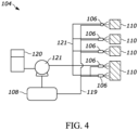
- the sensor cleaning system 104 includes one or more cleaning jets 106 and an electronic controller 108.
- the electronic controller 108 is configured to operate each of the cleaning jets 106 to clean one or more of the sensors 110.
- Each one of the cleaning jets 106 receives fluid from a fluid tank 120 via one or more feed lines (feed lines 119 of FIG. 4 ).
- feed lines 119 of FIG. 4 feed lines 119 of FIG. 4 .
- each cleaning jets 106 is positioned throughout the vehicle 102 such that it ejects fluid at at least one of the sensors 110.
- one or more of the sensors 110 are cleaned with fluid from more than one cleaning jet 106.
- the fluid tank 120 may include one or more heating elements and/or cooling elements (not shown). One or more heating and/or cooling elements may alternatively or additionally be disposed along the feed lines 119 and/or integrated into the cleaning jets 106. Each of heating elements and/or cooling elements may be communicatively coupled to and controlled by the electronic controller 108. In some embodiments, each of the cleaning jets 106 are fluidly coupled to the fluid tank 120 via a respective heated feed line and a respective cooling feed line.
- the feed lines 119 may also include one or more pumps (for example, pump 121) to control the flow and/or pressure of the fluid within the respective feed lines 119.
- the system 104 may include additional pumps (not shown) to control flow to a particular cleaning jet 106.
- the sensor cleaning system 104 may include additional components.
- the sensor cleaning system 104 may include one or more additional sensors 122.
- the sensors 122 may include one or more temperature sensors configured to measure a temperature of the fluid within the fluid tank 120, along the feed lines 119, or both.
- the sensors 122 may also include one or more pressure sensors configured to measure pressure of the fluid along the feed lines 119.
- one or more of the sensors 122 may be integrated into the each of the cleaning jets 106 and/or the tank 120.
- the sensors 122 may also include one or more image sensors. It should be noted that the autonomous driving system 108 and other vehicle systems 112 may receive and utilize information from the additional sensors 122.
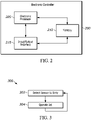
- FIG. 2 illustrates an exemplary embodiment of the electronic controller 108, which includes an electronic processor 205 (for example, a microprocessor, application specific integrated circuit, etc.), a memory 210, and an input/output interface 215.
- the memory 210 may be made up of one or more non-transitory computer-readable media and includes at least a program storage area and a data storage area.
- the program storage area and the data storage area can include combinations of different types of memory, such as read-only memory (“ROM”), random access memory (“RAM”) (for example, dynamic RAM (“DRAM'), synchronous DRAM (“SDRAM”), etc.), electrically erasable programmable read-only memory (“EEPROM'), flash memory, or other suitable memory devices.
- ROM read-only memory
- RAM random access memory
- DRAM' dynamic RAM
- SDRAM synchronous DRAM
- EEPROM' electrically erasable programmable read-only memory
- flash memory or other suitable memory devices.
- the electronic processor 205 is coupled to the memory 210 and the input/output interface 28.
- the electronic processor 205 sends and receives information (for example, from the memory 210 and/or the input/output interface 215), and processes the information by executing one or more software instructions or modules, capable of being stored in the memory 210, or another non-transitory computer readable medium.
- the software can include firmware, one or more applications, program data, filters, rules, one or more program modules, and other executable instructions.
- the electronic processor 205 is configured to retrieve from the memory 210 and execute, among other things, software for autonomous vehicle control, and for performing methods as described herein.
- the input/output interface 215 transmits and receives information from devices external to the electronic controller 108 over one or more wired and/or wireless connections, for example, components of the system 104 via the bus 114.
- the input/output interface 215 receives user input, provides system output, or a combination of both.
- the input/output interface 215 may also include other input and output mechanisms (for example, a transceiver, which is not shown), which for brevity are not described herein and which may be implemented in hardware, software, or a combination of both.
- the input/output interface 215 may also include one or more transceivers for the controller 108 to transmit and receive information from other vehicles.
- FIG. 2 illustrates only a single electronic processor 205, memory 210, and input/output interface 215, alternative embodiments of the electronic controller 104 may include multiple processing units, memory modules, and/or input/output interfaces.
- the system 100 may include other electronic controllers, each including similar components as, and configured similarly to, the electronic controller 200.
- the electronic controller 200 is implemented partially or entirely on a semiconductor (for example, a field-programmable gate array ["FPGA"] semiconductor) chip.
- the various modules and controllers described herein may be implemented as individual controllers, as illustrated, or as components of a single controller. In some embodiments, a combination of approaches may be used.
- the electronic controller 108 may include additional, fewer, or different components.
- the electronic controller 108 may include a transceiver or separate transmitting and receiving components, for example, a transmitter and a receiver. Some or all of the components of electronic controller 108 may be dispersed and/or integrated into other devices/components of the system 100 (for example, a vehicle control module or VCM, not shown, of the vehicle 102).
- FIG. 3 illustrates an exemplary method 300 of cleaning one or more dirty sensors of a vehicle (for example, the sensors 110).
- the method 300 is explained in terms of the electronic controller 108, in particular the electronic processor 205 and a single sensor of the sensors 110.
- portions of the method 300 may be distributed among multiple devices (for example, one or more additional controllers/processors of or connected to the system 100) and applied to more than one sensor at the same or at different times.
- the term "dirty" is used herein to describe when a sensor is coated, covered or affected with water, snow, ice, mud, sand, dirt, debris, bugs, tree sap, grease, and other items that may cover, coat, or collect on the sensor.
- the electronic processor 205 detects that one or more of the sensors 110 is dirty.
- the electronic processor 205 may detect that the sensor is dirty one or more ways. For example, the electronic processor 205 may determine that the sensor is dirty based on a determination that a reading from the sensor is incorrect. In some embodiments, the electronic processor 205 utilizes one or more of the sensors 122 to detect that the sensor is dirty. For example, the electronic processor 205 may analyze an image from an image sensor proximate to the sensor and determine from the image that the sensor is dirty. The electronic processor 205 may determine that the sensor is dirty by analyzing an output from an IR sensor. The electronic processor 205 may also detect that the sensor is dirty via a notification received from another vehicle (not shown) proximate to the vehicle 102.
- the other vehicle may detect, via an image sensor directed at the vehicle 102, that a sensor of the vehicle 102 is dirty and transmit, to the controller 108, a notification that the respective sensor is dirty.
- the electronic processor 205 may also determine a soil type of the dirt or substance covering or coating the sensor (for example, via analysis of the information collected from the sensors 122).
- the electronic processor 205 utilizes one or more artificial intelligence/machine learning algorithms to detect that one or more sensors 110 are dirty.
- the electronic processor 205 may generate a list of sensors of the sensors 110 that are dirty.
- the electronic processor 205 may further be configured to prioritize cleaning of particular sensors on the list.
- the electronic processor 205 operates one or more of the cleaning jets 106 such that fluid is ejected at the sensor at a predetermined pulse speed.
- the respective jet is operated such that a fast, alternating spray of fluid is emitted at the sensor that is dirty.
- a pulsated spray as opposed to a steady spray, reduces usage of the fluid of the tank 120.
- the pulsated spray emitted by the jets 106 may be an on-off alternating spray or, in some embodiments, a spray that alternates between different intensities.
- the predetermined pulse speed may be a preset pulse. In some embodiments, the predetermined pulse speed may be selected from a plurality of predetermined pulse speeds based on one or more factors. For example, the predetermined pulse speed may be selected based on the soil type that the sensor is dirty with. The predetermined pulse speed may also be selected based on a speed of the vehicle 102.
- the jet is operated for a predetermined time before the electronic processor 205 discontinues operation of the jet.
- the electronic processor 205 then returns to block 302.
- the electronic processor 205 evaluates whether the sensor is sufficiently cleaned.
- the electronic processor 205 may determine that the sensor is clean via one or more methods similar to those performed at block 302. For example, the electronic processor 205 may evaluate a second image from an image sensor proximate to the sensor to determine that the sensor is sufficiently cleaned.
- the electronic processor 205 is further configured to adjust one or more additional characteristics of the fluid output by the respective cleaning jet based on the soil type.
- the electronic processor 205 may be configured to adjust a temperature of the fluid (for example, via one or more of the heating/cooling elements of the system 104) and/or a pressure of the fluid output by the respective jet.
- the electronic processor 205 may adjust the pulse speed, temperature, and/or pressure of any individual cleaning jet based on additional factors. Additional factors may be sensor performance sensitivity to getting dirty, an average rate of how often the respective sensor gets dirty, a soil type, a shape of the vehicle 102, a speed of the vehicle 102, weather conditions, and the like.
- the electronic processor 205 is configured to adjust the pressure based on a speed of the vehicle 102.
- the electronic processor 205 may be configured to adjust the temperature of the fluid based on weather conditions. The location of the respective sensor may also be considered in the adjustment of one or more characteristics of the fluid.
- FIG. 5 is a flowchart 500 illustrating examples of cleaning methods implemented by the system 104 based on the soil type.
- the processor 205 may first determine whether the soil type is organic 502 or non-organic 504. Following the determination, the processor 205 further determines the particular soil type. For example, for organic soiling 502, the processor 205 determines whether the soiling is of an insect 506, tree sap 508, or grease 510 while if the soil type is non-organic 504, the processor 205 determines whether it is mud 512, salt 514, or ice 516. Based on the determined soil type, the processor 205 operates the respective cleaning jet(s) 106 accordingly.
- the fluid is heated and sprayed at a pulse speed (blocks 518) while for grease 510 (or an unidentifiable soiling type 505), the sensor is first sprayed at a pulse speed (block 520) before the fluid is heated (block 522).
- a or “contains ... a” does not, without more constraints, preclude the existence of additional identical elements in the process, method, article, or apparatus that comprises, has, includes, contains the element.
- the terms “a” and “an” are defined as one or more unless explicitly stated otherwise herein.
- the terms “substantially,” “essentially,” “approximately,” “about” or any other version thereof, are defined as being close to as understood by one of ordinary skill in the art, and in one non-limiting embodiment the term is defined to be within 10%, in another embodiment within 5%, in another embodiment within 1% and in another embodiment within 0.5%.
- the term “coupled” as used herein is defined as connected, although not necessarily directly and not necessarily mechanically.
- a device or structure that is “configured” in a certain way is configured in at least that way but may also be configured in ways that are not listed.
- embodiments provide, among other things, a cleaning system for a sensor of a vehicle.
- Various embodiments are set forth in the following claims.
Applications Claiming Priority (1)
| Application Number | Priority Date | Filing Date | Title |
|---|---|---|---|
| US202163230513P | 2021-08-06 | 2021-08-06 |
Publications (1)
| Publication Number | Publication Date |
|---|---|
| EP4129775A1 true EP4129775A1 (fr) | 2023-02-08 |
Family
ID=82786383
Family Applications (1)
| Application Number | Title | Priority Date | Filing Date |
|---|---|---|---|
| EP22187893.7A Pending EP4129775A1 (fr) | 2021-08-06 | 2022-07-29 | Nettoyage de capteur de véhicule autonome |
Country Status (3)
| Country | Link |
|---|---|
| US (1) | US20230045661A1 (fr) |
| EP (1) | EP4129775A1 (fr) |
| CN (1) | CN115703434A (fr) |
Citations (3)
| Publication number | Priority date | Publication date | Assignee | Title |
|---|---|---|---|---|
| EP2631734A1 (fr) * | 2012-02-23 | 2013-08-28 | The Raymond Corporation | Procédé et appareil pour l'élimination et la prévention d'embué d'une surface de lentille sur l'objectif d'un véhicule |
| US20200001331A1 (en) * | 2018-06-27 | 2020-01-02 | Geoffrey F. Deane | Systems and methods for perception surface cleaning, drying, and/or thermal management with fluid recirculation |
| WO2020023852A1 (fr) * | 2018-07-27 | 2020-01-30 | Actasys Inc. | Prévention de perte de transmission de signal radio et lumineux à travers une surface de transmission due à des conditions environnementales météorologiques et opératoires à l'aide d'actionneurs de commande de flux actifs |
-
2022
- 2022-07-29 EP EP22187893.7A patent/EP4129775A1/fr active Pending
- 2022-08-05 US US17/817,911 patent/US20230045661A1/en active Pending
- 2022-08-08 CN CN202210944315.6A patent/CN115703434A/zh active Pending
Patent Citations (3)
| Publication number | Priority date | Publication date | Assignee | Title |
|---|---|---|---|---|
| EP2631734A1 (fr) * | 2012-02-23 | 2013-08-28 | The Raymond Corporation | Procédé et appareil pour l'élimination et la prévention d'embué d'une surface de lentille sur l'objectif d'un véhicule |
| US20200001331A1 (en) * | 2018-06-27 | 2020-01-02 | Geoffrey F. Deane | Systems and methods for perception surface cleaning, drying, and/or thermal management with fluid recirculation |
| WO2020023852A1 (fr) * | 2018-07-27 | 2020-01-30 | Actasys Inc. | Prévention de perte de transmission de signal radio et lumineux à travers une surface de transmission due à des conditions environnementales météorologiques et opératoires à l'aide d'actionneurs de commande de flux actifs |
Also Published As
| Publication number | Publication date |
|---|---|
| US20230045661A1 (en) | 2023-02-09 |
| CN115703434A (zh) | 2023-02-17 |
Similar Documents
| Publication | Publication Date | Title |
|---|---|---|
| US11155258B2 (en) | System and method for radar cross traffic tracking and maneuver risk estimation | |
| CN106864454B (zh) | 用于辅助机动车辆的操纵过程的方法和装置 | |
| CN109649393B (zh) | 一种自动驾驶变换车道的路径规划方法及装置 | |
| US10209715B2 (en) | System and method of using crowd-sourced driving path data in an autonomous or semi-autonomous driving system | |
| US9429946B2 (en) | Driving control system and dynamic decision control method thereof | |
| US20200026277A1 (en) | Autonomous driving decisions at intersections using hierarchical options markov decision process | |
| US11370419B2 (en) | Use of driver assistance collision mitigation systems with autonomous driving systems | |
| CN109421628A (zh) | 协作的车辆操作 | |
| DE102013209575A1 (de) | Spurhaltesystem unter verwendung einer hinteren kamera | |
| KR20200109365A (ko) | Slam을 사용한 차량의 위치 보정 기법 | |
| US20200278423A1 (en) | Removing false alarms at the beamforming stage for sensing radars using a deep neural network | |
| JP2022535653A (ja) | 連結車両の許容可能な車両の状態空間を決定する方法 | |
| US20200180692A1 (en) | System and method to model steering characteristics | |
| WO2015121260A1 (fr) | Appareil et procédé destinés à être utilisés dans un véhicule | |
| CN113228131B (zh) | 用于提供周围环境数据的方法和系统 | |
| CN112435460A (zh) | 交通灯状态监控和交通灯到车道的分配的方法和系统 | |
| US11511733B2 (en) | Vehicle parking system | |
| US20220258727A1 (en) | Automated valet parking system, control method of automated valet parking system, and autonomous driving vehicle | |
| AU2022200113A1 (en) | Proactive lane change for autonomous vehicles | |
| EP4129775A1 (fr) | Nettoyage de capteur de véhicule autonome | |
| CN114084132A (zh) | 控制方法与装置、终端设备 | |
| US11555920B2 (en) | Estimating vehicle velocity using radar data | |
| CN116224232A (zh) | 基于雷达的对象高度估计 | |
| JP4923766B2 (ja) | 車両用制動力制御装置 | |
| US11214261B2 (en) | Learn association for multi-object tracking with multi sensory data and missing modalities |
Legal Events
| Date | Code | Title | Description |
|---|---|---|---|
| PUAI | Public reference made under article 153(3) epc to a published international application that has entered the european phase |
Free format text: ORIGINAL CODE: 0009012 |
|
| STAA | Information on the status of an ep patent application or granted ep patent |
Free format text: STATUS: THE APPLICATION HAS BEEN PUBLISHED |
|
| AK | Designated contracting states |
Kind code of ref document: A1 Designated state(s): AL AT BE BG CH CY CZ DE DK EE ES FI FR GB GR HR HU IE IS IT LI LT LU LV MC MK MT NL NO PL PT RO RS SE SI SK SM TR |
|
| STAA | Information on the status of an ep patent application or granted ep patent |
Free format text: STATUS: REQUEST FOR EXAMINATION WAS MADE |
|
| 17P | Request for examination filed |
Effective date: 20230808 |
|
| RBV | Designated contracting states (corrected) |
Designated state(s): AL AT BE BG CH CY CZ DE DK EE ES FI FR GB GR HR HU IE IS IT LI LT LU LV MC MK MT NL NO PL PT RO RS SE SI SK SM TR |