EP4129762A1 - Vehicle interior structure - Google Patents
Vehicle interior structure Download PDFInfo
- Publication number
- EP4129762A1 EP4129762A1 EP21781721.2A EP21781721A EP4129762A1 EP 4129762 A1 EP4129762 A1 EP 4129762A1 EP 21781721 A EP21781721 A EP 21781721A EP 4129762 A1 EP4129762 A1 EP 4129762A1
- Authority
- EP
- European Patent Office
- Prior art keywords
- windshield
- camera
- polarizing plate
- interior member
- polarizer
- Prior art date
- Legal status (The legal status is an assumption and is not a legal conclusion. Google has not performed a legal analysis and makes no representation as to the accuracy of the status listed.)
- Withdrawn
Links
- 239000011347 resin Substances 0.000 description 17
- 229920005989 resin Polymers 0.000 description 17
- 238000011282 treatment Methods 0.000 description 16
- 239000004372 Polyvinyl alcohol Substances 0.000 description 10
- 229920002451 polyvinyl alcohol Polymers 0.000 description 10
- 238000000034 method Methods 0.000 description 8
- -1 polypropylene Polymers 0.000 description 7
- 239000011521 glass Substances 0.000 description 6
- 229920000139 polyethylene terephthalate Polymers 0.000 description 6
- 239000005020 polyethylene terephthalate Substances 0.000 description 6
- 238000010521 absorption reaction Methods 0.000 description 5
- 238000004043 dyeing Methods 0.000 description 5
- 239000000463 material Substances 0.000 description 5
- 230000001681 protective effect Effects 0.000 description 5
- 238000007127 saponification reaction Methods 0.000 description 4
- 239000004925 Acrylic resin Substances 0.000 description 3
- 229920000178 Acrylic resin Polymers 0.000 description 3
- 239000004743 Polypropylene Substances 0.000 description 3
- 206010042674 Swelling Diseases 0.000 description 3
- 238000004132 cross linking Methods 0.000 description 3
- 230000000694 effects Effects 0.000 description 3
- 239000004973 liquid crystal related substance Substances 0.000 description 3
- 230000010287 polarization Effects 0.000 description 3
- 238000006116 polymerization reaction Methods 0.000 description 3
- 229920001155 polypropylene Polymers 0.000 description 3
- 230000008961 swelling Effects 0.000 description 3
- ZCYVEMRRCGMTRW-UHFFFAOYSA-N 7553-56-2 Chemical compound [I] ZCYVEMRRCGMTRW-UHFFFAOYSA-N 0.000 description 2
- 229920002284 Cellulose triacetate Polymers 0.000 description 2
- 229920000219 Ethylene vinyl alcohol Polymers 0.000 description 2
- NNLVGZFZQQXQNW-ADJNRHBOSA-N [(2r,3r,4s,5r,6s)-4,5-diacetyloxy-3-[(2s,3r,4s,5r,6r)-3,4,5-triacetyloxy-6-(acetyloxymethyl)oxan-2-yl]oxy-6-[(2r,3r,4s,5r,6s)-4,5,6-triacetyloxy-2-(acetyloxymethyl)oxan-3-yl]oxyoxan-2-yl]methyl acetate Chemical compound O([C@@H]1O[C@@H]([C@H]([C@H](OC(C)=O)[C@H]1OC(C)=O)O[C@H]1[C@@H]([C@@H](OC(C)=O)[C@H](OC(C)=O)[C@@H](COC(C)=O)O1)OC(C)=O)COC(=O)C)[C@@H]1[C@@H](COC(C)=O)O[C@@H](OC(C)=O)[C@H](OC(C)=O)[C@H]1OC(C)=O NNLVGZFZQQXQNW-ADJNRHBOSA-N 0.000 description 2
- 238000001035 drying Methods 0.000 description 2
- PNDPGZBMCMUPRI-UHFFFAOYSA-N iodine Chemical compound II PNDPGZBMCMUPRI-UHFFFAOYSA-N 0.000 description 2
- 229910052740 iodine Inorganic materials 0.000 description 2
- 239000011630 iodine Substances 0.000 description 2
- 238000004519 manufacturing process Methods 0.000 description 2
- 238000005406 washing Methods 0.000 description 2
- XLYOFNOQVPJJNP-UHFFFAOYSA-N water Substances O XLYOFNOQVPJJNP-UHFFFAOYSA-N 0.000 description 2
- 239000004976 Lyotropic liquid crystal Substances 0.000 description 1
- 239000004698 Polyethylene Substances 0.000 description 1
- 229920002877 acrylic styrene acrylonitrile Polymers 0.000 description 1
- 239000012790 adhesive layer Substances 0.000 description 1
- 150000001336 alkenes Chemical class 0.000 description 1
- 230000005540 biological transmission Effects 0.000 description 1
- 229920002678 cellulose Polymers 0.000 description 1
- 239000001913 cellulose Substances 0.000 description 1
- 150000001925 cycloalkenes Chemical class 0.000 description 1
- 239000005038 ethylene vinyl acetate Substances 0.000 description 1
- 238000004898 kneading Methods 0.000 description 1
- 239000000113 methacrylic resin Substances 0.000 description 1
- JFNLZVQOOSMTJK-KNVOCYPGSA-N norbornene Chemical compound C1[C@@H]2CC[C@H]1C=C2 JFNLZVQOOSMTJK-KNVOCYPGSA-N 0.000 description 1
- JRZJOMJEPLMPRA-UHFFFAOYSA-N olefin Natural products CCCCCCCC=C JRZJOMJEPLMPRA-UHFFFAOYSA-N 0.000 description 1
- 229920001200 poly(ethylene-vinyl acetate) Polymers 0.000 description 1
- 229920001225 polyester resin Polymers 0.000 description 1
- 229920000573 polyethylene Polymers 0.000 description 1
- 229920006254 polymer film Polymers 0.000 description 1
- 239000011118 polyvinyl acetate Substances 0.000 description 1
- 229920002689 polyvinyl acetate Polymers 0.000 description 1
- 229920000915 polyvinyl chloride Polymers 0.000 description 1
- 239000004800 polyvinyl chloride Substances 0.000 description 1
- QMRNDFMLWNAFQR-UHFFFAOYSA-N prop-2-enenitrile;prop-2-enoic acid;styrene Chemical compound C=CC#N.OC(=O)C=C.C=CC1=CC=CC=C1 QMRNDFMLWNAFQR-UHFFFAOYSA-N 0.000 description 1
- 239000002356 single layer Substances 0.000 description 1
- 239000000126 substance Substances 0.000 description 1
- 238000002834 transmittance Methods 0.000 description 1
Images
Classifications
-
- G—PHYSICS
- G03—PHOTOGRAPHY; CINEMATOGRAPHY; ANALOGOUS TECHNIQUES USING WAVES OTHER THAN OPTICAL WAVES; ELECTROGRAPHY; HOLOGRAPHY
- G03B—APPARATUS OR ARRANGEMENTS FOR TAKING PHOTOGRAPHS OR FOR PROJECTING OR VIEWING THEM; APPARATUS OR ARRANGEMENTS EMPLOYING ANALOGOUS TECHNIQUES USING WAVES OTHER THAN OPTICAL WAVES; ACCESSORIES THEREFOR
- G03B29/00—Combinations of cameras, projectors or photographic printing apparatus with non-photographic non-optical apparatus, e.g. clocks or weapons; Cameras having the shape of other objects
-
- B—PERFORMING OPERATIONS; TRANSPORTING
- B60—VEHICLES IN GENERAL
- B60R—VEHICLES, VEHICLE FITTINGS, OR VEHICLE PARTS, NOT OTHERWISE PROVIDED FOR
- B60R13/00—Elements for body-finishing, identifying, or decorating; Arrangements or adaptations for advertising purposes
- B60R13/02—Internal Trim mouldings ; Internal Ledges; Wall liners for passenger compartments; Roof liners
- B60R13/0256—Dashboard liners
-
- B—PERFORMING OPERATIONS; TRANSPORTING
- B60—VEHICLES IN GENERAL
- B60R—VEHICLES, VEHICLE FITTINGS, OR VEHICLE PARTS, NOT OTHERWISE PROVIDED FOR
- B60R11/00—Arrangements for holding or mounting articles, not otherwise provided for
- B60R11/04—Mounting of cameras operative during drive; Arrangement of controls thereof relative to the vehicle
-
- G—PHYSICS
- G03—PHOTOGRAPHY; CINEMATOGRAPHY; ANALOGOUS TECHNIQUES USING WAVES OTHER THAN OPTICAL WAVES; ELECTROGRAPHY; HOLOGRAPHY
- G03B—APPARATUS OR ARRANGEMENTS FOR TAKING PHOTOGRAPHS OR FOR PROJECTING OR VIEWING THEM; APPARATUS OR ARRANGEMENTS EMPLOYING ANALOGOUS TECHNIQUES USING WAVES OTHER THAN OPTICAL WAVES; ACCESSORIES THEREFOR
- G03B11/00—Filters or other obturators specially adapted for photographic purposes
- G03B11/04—Hoods or caps for eliminating unwanted light from lenses, viewfinders or focusing aids
- G03B11/041—Lens caps as separate accessory
-
- B—PERFORMING OPERATIONS; TRANSPORTING
- B60—VEHICLES IN GENERAL
- B60R—VEHICLES, VEHICLE FITTINGS, OR VEHICLE PARTS, NOT OTHERWISE PROVIDED FOR
- B60R11/00—Arrangements for holding or mounting articles, not otherwise provided for
- B60R2011/0001—Arrangements for holding or mounting articles, not otherwise provided for characterised by position
- B60R2011/0003—Arrangements for holding or mounting articles, not otherwise provided for characterised by position inside the vehicle
- B60R2011/0026—Windows, e.g. windscreen
-
- B—PERFORMING OPERATIONS; TRANSPORTING
- B60—VEHICLES IN GENERAL
- B60R—VEHICLES, VEHICLE FITTINGS, OR VEHICLE PARTS, NOT OTHERWISE PROVIDED FOR
- B60R13/00—Elements for body-finishing, identifying, or decorating; Arrangements or adaptations for advertising purposes
- B60R13/02—Internal Trim mouldings ; Internal Ledges; Wall liners for passenger compartments; Roof liners
- B60R2013/0287—Internal Trim mouldings ; Internal Ledges; Wall liners for passenger compartments; Roof liners integrating other functions or accessories
-
- G—PHYSICS
- G02—OPTICS
- G02B—OPTICAL ELEMENTS, SYSTEMS OR APPARATUS
- G02B27/00—Optical systems or apparatus not provided for by any of the groups G02B1/00 - G02B26/00, G02B30/00
- G02B27/28—Optical systems or apparatus not provided for by any of the groups G02B1/00 - G02B26/00, G02B30/00 for polarising
- G02B27/281—Optical systems or apparatus not provided for by any of the groups G02B1/00 - G02B26/00, G02B30/00 for polarising used for attenuating light intensity, e.g. comprising rotatable polarising elements
-
- G—PHYSICS
- G02—OPTICS
- G02B—OPTICAL ELEMENTS, SYSTEMS OR APPARATUS
- G02B5/00—Optical elements other than lenses
- G02B5/30—Polarising elements
-
- H—ELECTRICITY
- H04—ELECTRIC COMMUNICATION TECHNIQUE
- H04N—PICTORIAL COMMUNICATION, e.g. TELEVISION
- H04N23/00—Cameras or camera modules comprising electronic image sensors; Control thereof
-
- H—ELECTRICITY
- H04—ELECTRIC COMMUNICATION TECHNIQUE
- H04N—PICTORIAL COMMUNICATION, e.g. TELEVISION
- H04N23/00—Cameras or camera modules comprising electronic image sensors; Control thereof
- H04N23/50—Constructional details
- H04N23/55—Optical parts specially adapted for electronic image sensors; Mounting thereof
Definitions
- the present invention relates to a vehicle interior structure, and more specifically, to a vehicle interior structure including a windshield, an interior member, and a camera, in which an image of reflection of the interior member on the windshield is hardly taken with the camera.
- a vehicle such as an automobile may be mounted with a camera for taking an image of the front of the vehicle through the windshield thereof (e.g., a camera for a dashboard camera, a camera for a driving support system, or a camera for a self-driving system) .
- a camera for taking an image of the front of the vehicle through the windshield thereof e.g., a camera for a dashboard camera, a camera for a driving support system, or a camera for a self-driving system
- Such camera may involve the occurrence of a problem in that an interior member (e.g., the upper surface of an instrument panel) is reflected on the windshield and the reflection inhibits the function of the camera. It is particularly important for each of a camera for driving support and a camera for self-driving to sufficiently and stably exhibit its performance without being affected by the reflection.
- the present invention has been made to solve the above-mentioned problem, and an object of the present invention is to provide a vehicle interior structure including a windshield, an interior member, and a camera, in which an image of the reflection of the interior member on the windshield is hardly taken with the camera.
- a vehicle interior structure including: a windshield; an interior member arranged below the windshield; and a camera arranged behind the windshield, wherein the vehicle interior structure further includes a polarizing plate arranged between the windshield and the camera, and wherein the polarizing plate is arranged so as to transmit a larger quantity of P-polarized light than that of S-polarized light.
- the interior member has a surface having an angle of from 20° to 120° with respect to the windshield.
- the vehicle interior structure including the windshield, the interior member, and the camera, in which an image of the reflection of the interior member on the windshield is hardly taken with the camera, can be provided.
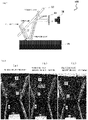
- FIG. 1 is a schematic view for illustrating a vehicle interior structure according to one embodiment of the present invention.
- a vehicle interior structure 100 includes: a windshield 10; an interior member 20 arranged below the windshield 10; and a camera 30 arranged behind the windshield 10.
- the interior member 20 may be arranged at the position at which light that has passed through the windshield 10 arrives.
- the interior structure 100 is configured so that at least part of the interior member 20 and the projection of the windshield 10 in a vertical direction may overlap each other.
- the camera 30 may be arranged at the position at which light, which has passed through the windshield 10, has been reflected on the interior member 20, and has been reflected on the windshield 10, arrives.
- a polarizing plate 40 is arranged between the windshield 10 and the camera 30.
- the polarizing plate 40 is arranged so that the light, which has passed through the windshield 10, has been reflected on the interior member 20, and has been reflected on the windshield 10, may pass through the polarizing plate 40 during its arrival from the windshield 10 at the camera 30 (substantially the lens of the camera).
- the polarizing plate 40 is arranged so as to transmit a larger quantity of P-polarized light than that of S-polarized light.
- the vehicle interior structure is configured as described above, and hence an image of the reflection of the interior member on the windshield can be prevented from being taken with the camera. More specifically, while the reflectance of the P-polarized light on the windshield is low, the reflectance of the S-polarized light on the windshield is high, that is, the S-polarized light is responsible for the reflectance. However, when the S-polarized light is cut off with the polarizing plate, an image of the reflection of the interior member on the windshield can be prevented from being taken with the camera. With regard to light from the front of the windshield, the P-polarized light passes through the windshield and the polarizing plate to arrive at the camera, and hence an image of the front can be satisfactorily taken.
- the interior member is configured to reflect a larger quantity of P-polarized light than that of S-polarized light.
- the interior member configured as described above has a polarizing function. Any appropriate material may be used as a material that expresses polarization, and examples thereof include: a polarizing plate; and a resin material having incorporated thereinto iodine, a dye, a liquid crystal, or the like.
- the interior member preferably has a surface having an angle of from 20° to 120° with respect to the windshield, more preferably has a surface having an angle of from 30° to 90° with respect thereto, and still more preferably has a surface having an angle of from 40° to 70° with respect thereto.
- the interior member and the windshield are arranged at such angle, light reflected on the interior member can be caused to enter the windshield at an angle close to Brewster's angle, and hence the reflection of P-polarized light on the windshield can be reduced.
- the quantity of the light passing through the polarizing plate further reduces, and hence the effect of the present invention becomes remarkable.
- an angle between the curved surface and the interior member is specified by the tangent plane of the curved surface.
- the interior member may be, for example, an instrument panel, and may be a formed body formed of a low-density resin, such as polypropylene, foamed polypropylene, polyvinyl chloride, or acrylonitrile-styrene acrylate.
- a low-density resin such as polypropylene, foamed polypropylene, polyvinyl chloride, or acrylonitrile-styrene acrylate.
- the polarizing plate includes a polarizer.
- the polarizing plate typically further includes a protective film arranged on at least one side of the polarizer.
- the polarizer is not particularly limited, and may be an absorption type or a reflection type.
- the polarizing plate may include a material that can cause polarization, such as iodine, a dye, or a liquid crystal.
- the polarizing plate When the polarizing plate uses an absorption-type polarizer, the polarizing plate is preferably arranged so that the absorption axis of the polarizer may be horizontal, and when the polarizing plate uses a reflection-type polarizer, the polarizing plate is preferably arranged so that the reflection axis of the polarizer may be horizontal. In other words, the polarizing plate is preferably arranged so that a plane including the transmission axis of the polarizer and the normal of the polarizing plate, and the windshield may be substantially perpendicular to each other. Through such arrangement, S-polarized light can be effectively cut off, and hence the effect of the present invention becomes remarkable.
- substantially perpendicular is a concept including not only a case in which both the planes are strictly perpendicular to each other but also a case in which an angle formed by both the planes is 90° ⁇ 10° (preferably 90° ⁇ 5°).
- the thickness of the polarizing plate is preferably from 5 ⁇ m to 300 ⁇ m, more preferably from 10 ⁇ m to 250 ⁇ m, still more preferably from 25 ⁇ m to 200 ⁇ m, particularly preferably from 25 ⁇ m to 100 ⁇ m.
- the thickness of the polarizer is not particularly limited, and an appropriate thickness may be adopted depending on purposes.
- the thickness is typically from about 1 um to about 80 um.
- the polarizer preferably exhibits absorption dichroism at any wavelength in the wavelength range of from 380 nm to 780 nm.
- the polarizer has a single layer transmittance of preferably 35% or more, more preferably 38% or more, still more preferably 40% or more, particularly preferably 42% or more.
- the polarizer has a polarization degree of preferably 90% or more, more preferably 92% or more, still more preferably 95% or more, particularly preferably 98% or more.
- the polarizer is preferably an iodine-based polarizer. More specifically, the polarizer may be formed of an iodine-containing polyvinyl alcohol-based resin (hereinafter referred to as "PVA-based resin”) film.
- PVA-based resin polyvinyl alcohol-based resin
- any appropriate resin may be adopted as a PVA-based resin for forming the PVA-based resin film.
- the resin include polyvinyl alcohol and an ethylene-vinyl alcohol copolymer.
- the polyvinyl alcohol is obtained by saponifying polyvinyl acetate.
- the ethylene-vinyl alcohol copolymer is obtained by saponifying an ethylene-vinyl acetate copolymer.
- the saponification degree of the PVA-based resin is typically from 85 mol% to 100 mol%, preferably from 95.0 mol% to 99.95 mol%, more preferably from 99.0 mol% to 99.93 mol%.
- the saponification degree may be determined in conformity with JIS K 6726-1994.
- the use of the PVA-based resin having such saponification degree can provide a polarizer excellent in durability. When the saponification degree is excessively high, gelling may occur.
- the average polymerization degree of the PVA-based resin may be appropriately selected depending on purposes.
- the average polymerization degree is typically from 1,000 to 10,000, preferably from 1,200 to 5,000, more preferably from 1,500 to 4,500.
- the average polymerization degree may be determined in conformity with JIS K 6726-1994.
- a method of obtaining the polarizer from the PVA-based resin film is generally a method of producing the polarizer through a series of treatment processes including swelling, dyeing, cross-linking, stretching, water washing, and drying.
- the order of the respective treatments that is, the swelling, the dyeing, the cross-linking, the stretching, the water washing, and the drying in each treatment process, the number of times of each of the treatments, and whether or not each of the treatments is performed are not particularly limited, and some of the treatments may be simultaneously performed in one treatment process, or some of the treatments may not be performed.
- the stretching treatment may be performed after the dyeing treatment, or may be performed simultaneously with, for example, the swelling treatment and the dyeing treatment.
- the dyeing treatment may be performed after the stretching treatment has been performed. Further, a method including performing the cross-linking treatment before or after the stretching treatment is used.
- a method of producing the polarizer is not limited to the above-mentioned production method, and the polarizer may be produced by using any other production method. For example, a dry stretching method may be used, or a polarizer, which is obtained by kneading a dichroic substance into a polymer film made of polyethylene terephthalate (PET) or the like, forming the kneaded product into a film, and stretching the film, is permitted.
- PET polyethylene terephthalate
- an O-type polarizer obtained by incorporating, into a liquid crystal aligned in a uniaxial direction, which serves as a host, a dichroic dye serving as a guest ( US 5523863 A or JP 03-503322 A ), or an E-type polarizer using a dichroic lyotropic liquid crystal ( US 6049428 A ) is permitted.
- a material for forming the protective film is, for example, a polyester-based resin such as polyethylene terephthalate (PET), a cellulose-based resin such as triacetylcellulose (TAC), a cycloolefin-based resin such as a norbornene-based resin, an olefin-based resin, such as polyethylene or polypropylene, or a (meth)acrylic resin.
- PET polyethylene terephthalate
- TAC triacetylcellulose
- a cycloolefin-based resin such as a norbornene-based resin
- an olefin-based resin such as polyethylene or polypropylene
- (meth)acrylic resin a (meth)acrylic resin.
- PET polyethylene terephthalate
- (meth) acrylic resin refers to an acrylic resin and/or a methacrylic resin.
- the protective film and the polarizer are laminated via any appropriate adhesive layer.
- the thickness of the protective film is preferably from 4 um to 250 um, more preferably from 5 um to 150 um, still more preferably from 10 ⁇ m to 100 ⁇ m, particularly preferably from 10 ⁇ m to 50 ⁇ m.
- the camera may be, for example, a camera for a dashboard camera, a camera for a driving support system, or a camera for a self-driving system.
- Example Reference Example
- present invention is not limited to Example (Reference Example).
- FIG. 2(a) a light-colored object B was arranged on a black desk A, and the desk and the object were regarded as an interior member.
- a glass plate C regarded as a windshield was arranged above the desk A having arranged thereon the light-colored object B so that an angle formed by the desk A and the glass plate C became 60°.
- a red object D was arranged on the front of the glass plate C opposite to the desk A. Then, an image of the red object D was taken with a camera from the rear of the glass plate.
- FIG. 2(a) (and FIGS. 2 (b) and 2(c) ) are photographs taken with the camera. According to such configuration, an image of the reflection of the light-colored object B was taken.
- a polarizing plate was arranged between the camera and the glass plate C so that its absorption axis was parallel to a vertical direction, followed by taking of an image of the red object D. According even to such configuration, an image of the reflection of the light-colored object B was taken.
- the polarizing plate was arranged between the camera and the glass plate C so that its absorption axis was parallel to a horizontal direction, followed by taking of an image of the red object D. According to such configuration, an image of the reflection of the light-colored object B was prevented from being taken.
Landscapes
- Physics & Mathematics (AREA)
- General Physics & Mathematics (AREA)
- Engineering & Computer Science (AREA)
- Mechanical Engineering (AREA)
- Optics & Photonics (AREA)
- Polarising Elements (AREA)
- Blocking Light For Cameras (AREA)
- Studio Devices (AREA)
Abstract
Description
- The present invention relates to a vehicle interior structure, and more specifically, to a vehicle interior structure including a windshield, an interior member, and a camera, in which an image of reflection of the interior member on the windshield is hardly taken with the camera.
- A vehicle such as an automobile may be mounted with a camera for taking an image of the front of the vehicle through the windshield thereof (e.g., a camera for a dashboard camera, a camera for a driving support system, or a camera for a self-driving system) . Such camera may involve the occurrence of a problem in that an interior member (e.g., the upper surface of an instrument panel) is reflected on the windshield and the reflection inhibits the function of the camera. It is particularly important for each of a camera for driving support and a camera for self-driving to sufficiently and stably exhibit its performance without being affected by the reflection.
- [PTL 1]
JP 2014-084071 A - The present invention has been made to solve the above-mentioned problem, and an object of the present invention is to provide a vehicle interior structure including a windshield, an interior member, and a camera, in which an image of the reflection of the interior member on the windshield is hardly taken with the camera.
- According to one embodiment of the present invention, there is provided a vehicle interior structure, including: a windshield; an interior member arranged below the windshield; and a camera arranged behind the windshield, wherein the vehicle interior structure further includes a polarizing plate arranged between the windshield and the camera, and wherein the polarizing plate is arranged so as to transmit a larger quantity of P-polarized light than that of S-polarized light.
- In one embodiment, the interior member has a surface having an angle of from 20° to 120° with respect to the windshield.
- According to the present invention, the vehicle interior structure including the windshield, the interior member, and the camera, in which an image of the reflection of the interior member on the windshield is hardly taken with the camera, can be provided.
-
-
FIG. 1 is a schematic view for illustrating a vehicle interior structure according to one embodiment of the present invention. -
FIGS. 2 are photographic views for showing the contents of Reference Example. -
FIG. 1 is a schematic view for illustrating a vehicle interior structure according to one embodiment of the present invention. A vehicleinterior structure 100 according to this embodiment includes: awindshield 10; aninterior member 20 arranged below thewindshield 10; and acamera 30 arranged behind thewindshield 10. Theinterior member 20 may be arranged at the position at which light that has passed through thewindshield 10 arrives. In one embodiment, theinterior structure 100 is configured so that at least part of theinterior member 20 and the projection of thewindshield 10 in a vertical direction may overlap each other. Thecamera 30 may be arranged at the position at which light, which has passed through thewindshield 10, has been reflected on theinterior member 20, and has been reflected on thewindshield 10, arrives. - A polarizing
plate 40 is arranged between thewindshield 10 and thecamera 30. In other words, the polarizingplate 40 is arranged so that the light, which has passed through thewindshield 10, has been reflected on theinterior member 20, and has been reflected on thewindshield 10, may pass through the polarizingplate 40 during its arrival from thewindshield 10 at the camera 30 (substantially the lens of the camera). - The polarizing
plate 40 is arranged so as to transmit a larger quantity of P-polarized light than that of S-polarized light. - According to the present invention, the vehicle interior structure is configured as described above, and hence an image of the reflection of the interior member on the windshield can be prevented from being taken with the camera. More specifically, while the reflectance of the P-polarized light on the windshield is low, the reflectance of the S-polarized light on the windshield is high, that is, the S-polarized light is responsible for the reflectance. However, when the S-polarized light is cut off with the polarizing plate, an image of the reflection of the interior member on the windshield can be prevented from being taken with the camera. With regard to light from the front of the windshield, the P-polarized light passes through the windshield and the polarizing plate to arrive at the camera, and hence an image of the front can be satisfactorily taken.
- As described above, the interior member is configured to reflect a larger quantity of P-polarized light than that of S-polarized light. In one embodiment, the interior member configured as described above has a polarizing function. Any appropriate material may be used as a material that expresses polarization, and examples thereof include: a polarizing plate; and a resin material having incorporated thereinto iodine, a dye, a liquid crystal, or the like.
- The interior member preferably has a surface having an angle of from 20° to 120° with respect to the windshield, more preferably has a surface having an angle of from 30° to 90° with respect thereto, and still more preferably has a surface having an angle of from 40° to 70° with respect thereto. When the interior member and the windshield are arranged at such angle, light reflected on the interior member can be caused to enter the windshield at an angle close to Brewster's angle, and hence the reflection of P-polarized light on the windshield can be reduced. As a result, the quantity of the light passing through the polarizing plate further reduces, and hence the effect of the present invention becomes remarkable. When the interior member has a curved surface, an angle between the curved surface and the interior member is specified by the tangent plane of the curved surface.
- The interior member may be, for example, an instrument panel, and may be a formed body formed of a low-density resin, such as polypropylene, foamed polypropylene, polyvinyl chloride, or acrylonitrile-styrene acrylate.
- In one embodiment, the polarizing plate includes a polarizer. The polarizing plate typically further includes a protective film arranged on at least one side of the polarizer. The polarizer is not particularly limited, and may be an absorption type or a reflection type. In addition, the polarizing plate may include a material that can cause polarization, such as iodine, a dye, or a liquid crystal.
- When the polarizing plate uses an absorption-type polarizer, the polarizing plate is preferably arranged so that the absorption axis of the polarizer may be horizontal, and when the polarizing plate uses a reflection-type polarizer, the polarizing plate is preferably arranged so that the reflection axis of the polarizer may be horizontal. In other words, the polarizing plate is preferably arranged so that a plane including the transmission axis of the polarizer and the normal of the polarizing plate, and the windshield may be substantially perpendicular to each other. Through such arrangement, S-polarized light can be effectively cut off, and hence the effect of the present invention becomes remarkable. The phrase "substantially perpendicular" is a concept including not only a case in which both the planes are strictly perpendicular to each other but also a case in which an angle formed by both the planes is 90°±10° (preferably 90°±5°).
- The thickness of the polarizing plate is preferably from 5 µm to 300 µm, more preferably from 10 µm to 250 µm, still more preferably from 25 µm to 200 µm, particularly preferably from 25 µm to 100 µm.
- The thickness of the polarizer is not particularly limited, and an appropriate thickness may be adopted depending on purposes. The thickness is typically from about 1 um to about 80 um.
- The polarizer preferably exhibits absorption dichroism at any wavelength in the wavelength range of from 380 nm to 780 nm. The polarizer has a single layer transmittance of preferably 35% or more, more preferably 38% or more, still more preferably 40% or more, particularly preferably 42% or more. The polarizer has a polarization degree of preferably 90% or more, more preferably 92% or more, still more preferably 95% or more, particularly preferably 98% or more.
- The polarizer is preferably an iodine-based polarizer. More specifically, the polarizer may be formed of an iodine-containing polyvinyl alcohol-based resin (hereinafter referred to as "PVA-based resin") film.
- Any appropriate resin may be adopted as a PVA-based resin for forming the PVA-based resin film. Examples of the resin include polyvinyl alcohol and an ethylene-vinyl alcohol copolymer. The polyvinyl alcohol is obtained by saponifying polyvinyl acetate. The ethylene-vinyl alcohol copolymer is obtained by saponifying an ethylene-vinyl acetate copolymer. The saponification degree of the PVA-based resin is typically from 85 mol% to 100 mol%, preferably from 95.0 mol% to 99.95 mol%, more preferably from 99.0 mol% to 99.93 mol%. The saponification degree may be determined in conformity with JIS K 6726-1994. The use of the PVA-based resin having such saponification degree can provide a polarizer excellent in durability. When the saponification degree is excessively high, gelling may occur.
- The average polymerization degree of the PVA-based resin may be appropriately selected depending on purposes. The average polymerization degree is typically from 1,000 to 10,000, preferably from 1,200 to 5,000, more preferably from 1,500 to 4,500. The average polymerization degree may be determined in conformity with JIS K 6726-1994.
- A method of obtaining the polarizer from the PVA-based resin film is generally a method of producing the polarizer through a series of treatment processes including swelling, dyeing, cross-linking, stretching, water washing, and drying. At this time, the order of the respective treatments, that is, the swelling, the dyeing, the cross-linking, the stretching, the water washing, and the drying in each treatment process, the number of times of each of the treatments, and whether or not each of the treatments is performed are not particularly limited, and some of the treatments may be simultaneously performed in one treatment process, or some of the treatments may not be performed. For example, the stretching treatment may be performed after the dyeing treatment, or may be performed simultaneously with, for example, the swelling treatment and the dyeing treatment. In addition, the dyeing treatment may be performed after the stretching treatment has been performed. Further, a method including performing the cross-linking treatment before or after the stretching treatment is used. In addition, a method of producing the polarizer is not limited to the above-mentioned production method, and the polarizer may be produced by using any other production method. For example, a dry stretching method may be used, or a polarizer, which is obtained by kneading a dichroic substance into a polymer film made of polyethylene terephthalate (PET) or the like, forming the kneaded product into a film, and stretching the film, is permitted. Alternatively, for example, an O-type polarizer obtained by incorporating, into a liquid crystal aligned in a uniaxial direction, which serves as a host, a dichroic dye serving as a guest (
US 5523863 A orJP 03-503322 A US 6049428 A ) is permitted. - Any appropriate resin film may be adopted as the protective film. A material for forming the protective film is, for example, a polyester-based resin such as polyethylene terephthalate (PET), a cellulose-based resin such as triacetylcellulose (TAC), a cycloolefin-based resin such as a norbornene-based resin, an olefin-based resin, such as polyethylene or polypropylene, or a (meth)acrylic resin. Of those, polyethylene terephthalate (PET) is preferred. The term " (meth) acrylic resin" refers to an acrylic resin and/or a methacrylic resin.
- The protective film and the polarizer are laminated via any appropriate adhesive layer.
- The thickness of the protective film is preferably from 4 um to 250 um, more preferably from 5 um to 150 um, still more preferably from 10 µm to 100 µm, particularly preferably from 10 µm to 50 µm.
- Any appropriate camera may be used as the camera. The camera may be, for example, a camera for a dashboard camera, a camera for a driving support system, or a camera for a self-driving system.
- The present invention is specifically described below by way of Example (Reference Example), but the present invention is not limited to Example (Reference Example).
- As shown in
FIG. 2(a) , a light-colored object B was arranged on a black desk A, and the desk and the object were regarded as an interior member. In addition, a glass plate C regarded as a windshield was arranged above the desk A having arranged thereon the light-colored object B so that an angle formed by the desk A and the glass plate C became 60°. Further, a red object D was arranged on the front of the glass plate C opposite to the desk A. Then, an image of the red object D was taken with a camera from the rear of the glass plate.FIG. 2(a) (and FIGS. 2 (b) and 2(c) ) are photographs taken with the camera. According to such configuration, an image of the reflection of the light-colored object B was taken. - In addition, in
FIG. 2(b) , a polarizing plate was arranged between the camera and the glass plate C so that its absorption axis was parallel to a vertical direction, followed by taking of an image of the red object D. According even to such configuration, an image of the reflection of the light-colored object B was taken. - Meanwhile, in
FIG. 2(c) , the polarizing plate was arranged between the camera and the glass plate C so that its absorption axis was parallel to a horizontal direction, followed by taking of an image of the red object D. According to such configuration, an image of the reflection of the light-colored object B was prevented from being taken. -
- 10
- windshield
- 20
- interior member
- 100
- vehicle interior structure
Claims (2)
- A vehicle interior structure, comprising:a windshield;an interior member arranged below the windshield; anda camera arranged behind the windshield,wherein the vehicle interior structure further comprises a polarizing plate arranged between the windshield and the camera, andwherein the polarizing plate is arranged so as to transmit a larger quantity of P-polarized light than that of S-polarized light.
- The vehicle interior structure according to claim 1, wherein the interior member has a surface having an angle of from 20° to 120° with respect to the windshield.
Applications Claiming Priority (2)
| Application Number | Priority Date | Filing Date | Title |
|---|---|---|---|
| JP2020066537A JP2021162793A (en) | 2020-04-02 | 2020-04-02 | Vehicle interior structure |
| PCT/JP2021/011923 WO2021200388A1 (en) | 2020-04-02 | 2021-03-23 | Vehicle interior structure |
Publications (1)
| Publication Number | Publication Date |
|---|---|
| EP4129762A1 true EP4129762A1 (en) | 2023-02-08 |
Family
ID=77929863
Family Applications (1)
| Application Number | Title | Priority Date | Filing Date |
|---|---|---|---|
| EP21781721.2A Withdrawn EP4129762A1 (en) | 2020-04-02 | 2021-03-23 | Vehicle interior structure |
Country Status (7)
| Country | Link |
|---|---|
| US (1) | US20230120225A1 (en) |
| EP (1) | EP4129762A1 (en) |
| JP (1) | JP2021162793A (en) |
| KR (1) | KR20220163379A (en) |
| CN (1) | CN115379958A (en) |
| TW (1) | TW202206312A (en) |
| WO (1) | WO2021200388A1 (en) |
Family Cites Families (22)
| Publication number | Priority date | Publication date | Assignee | Title |
|---|---|---|---|---|
| US5523863A (en) | 1988-10-19 | 1996-06-04 | Fergason; James L. | Controlled liquid crystal optical polarizer method and apparatus |
| EP0394416A4 (en) | 1988-10-19 | 1992-07-08 | James L. Fergason | Variable density light control apparatus and method |
| US6049428A (en) | 1994-11-18 | 2000-04-11 | Optiva, Inc. | Dichroic light polarizers |
| JPH0983879A (en) * | 1995-09-18 | 1997-03-28 | Mitsubishi Electric Corp | In-vehicle camera device |
| JP2001094842A (en) * | 1999-09-22 | 2001-04-06 | Fuji Heavy Ind Ltd | Prevention of glare in vehicle cameras |
| US8467129B2 (en) * | 2007-05-31 | 2013-06-18 | Ppg Industries Ohio, Inc. | Veiling glare reduction system and method of controlling reflection from a vehicle windshield |
| JP5417773B2 (en) * | 2008-09-03 | 2014-02-19 | 株式会社ニコン | On-vehicle camera and optical device |
| WO2011043117A1 (en) * | 2009-10-05 | 2011-04-14 | 本田技研工業株式会社 | Vehicle interior material |
| DE102009052354A1 (en) * | 2009-11-07 | 2011-05-12 | Audi Ag | Pane e.g. front pane, for passenger car, has polarization filter oriented such that filter exhibits minimum transmission for s-polarized light below angle to normal of pane, where angle lies in specific range |
| JP6095047B2 (en) * | 2012-10-26 | 2017-03-15 | ダイハツ工業株式会社 | Window reflection evaluation method |
| JP2015099362A (en) * | 2013-10-15 | 2015-05-28 | 日東電工株式会社 | Optical layered body and dimming window |
| JP6277749B2 (en) * | 2014-02-04 | 2018-02-14 | 株式会社デンソー | In-vehicle optical transceiver |
| US9658376B2 (en) * | 2014-04-17 | 2017-05-23 | Corning Incorporated | Polarizing article and method for making the same |
| US10088616B2 (en) * | 2014-09-19 | 2018-10-02 | Toyota Motor Engineering & Manufacturing North America, Inc. | Panel with reduced glare |
| JP6571935B2 (en) * | 2015-01-14 | 2019-09-04 | 日東電工株式会社 | Video display mirror for vehicles |
| JP6425570B2 (en) * | 2015-02-02 | 2018-11-21 | 日東電工株式会社 | Vehicle with mirror with image display |
| JP2017190017A (en) * | 2016-04-12 | 2017-10-19 | 林テレンプ株式会社 | Vehicular interior article |
| US10527759B2 (en) * | 2016-04-18 | 2020-01-07 | Toyota Motor Engineering & Manufacturing North America, Inc. | Anti-glare panels |
| JP6415649B1 (en) * | 2017-07-05 | 2018-10-31 | 三菱電機株式会社 | Car camera |
| JP2019014455A (en) * | 2017-07-11 | 2019-01-31 | 林テレンプ株式会社 | Interior member for vehicle, reflective polarizing element used for interior member, and method for manufacturing the same |
| JP6812933B2 (en) * | 2017-09-19 | 2021-01-13 | トヨタ自動車株式会社 | Manufacturing method of interior members and manufacturing method of polarizing members |
| US11619826B2 (en) * | 2018-04-17 | 2023-04-04 | Samsung Electronics Co., Ltd. | Augmented reality (AR) display apparatus and method |
-
2020
- 2020-04-02 JP JP2020066537A patent/JP2021162793A/en active Pending
-
2021
- 2021-03-23 WO PCT/JP2021/011923 patent/WO2021200388A1/en not_active Ceased
- 2021-03-23 KR KR1020227033133A patent/KR20220163379A/en not_active Withdrawn
- 2021-03-23 US US17/915,664 patent/US20230120225A1/en not_active Abandoned
- 2021-03-23 EP EP21781721.2A patent/EP4129762A1/en not_active Withdrawn
- 2021-03-23 CN CN202180026780.5A patent/CN115379958A/en active Pending
- 2021-03-26 TW TW110111176A patent/TW202206312A/en unknown
Also Published As
| Publication number | Publication date |
|---|---|
| KR20220163379A (en) | 2022-12-09 |
| JP2021162793A (en) | 2021-10-11 |
| TW202206312A (en) | 2022-02-16 |
| CN115379958A (en) | 2022-11-22 |
| WO2021200388A1 (en) | 2021-10-07 |
| US20230120225A1 (en) | 2023-04-20 |
Similar Documents
| Publication | Publication Date | Title |
|---|---|---|
| KR100679535B1 (en) | Polarizer, polarizer and liquid crystal display using the same | |
| JP2001296427A (en) | Method for manufacturing polarizing plate and liquid crystal display device | |
| JPWO2007102327A1 (en) | Polarizing plate and liquid crystal display device | |
| JP2001235625A (en) | Polarizer | |
| KR20240155226A (en) | Indication system, indication method, indication body and method for manufacturing indication body | |
| JP2014132313A (en) | Manufacturing method of polarizing plate, polarizing plate, laminated optical member, and image display device | |
| JP2001272544A (en) | Polarizer | |
| WO2020209354A1 (en) | Laminated-type wave plate, polarizing plate, circularly polarizing plates and display device | |
| EP4129762A1 (en) | Vehicle interior structure | |
| US20190025487A1 (en) | Polarizing plate | |
| JP3373492B2 (en) | Polarizer | |
| JP3609563B2 (en) | Wide-field polarizing plate | |
| KR100866005B1 (en) | Polarizing plate, manufacturing method thereof, and liquid crystal display device | |
| US20230135197A1 (en) | Reflection prevention structure | |
| KR20040078649A (en) | Circularly polarizing plate and liquid crystal display device | |
| JP2001290025A (en) | Polarizing plate, method of manufacturing the same, and liquid crystal display | |
| KR20220044425A (en) | Polarizing plate and organic el display device | |
| US20260016623A1 (en) | Laminate and virtual reality display device | |
| TWI904412B (en) | Display method | |
| TWI904413B (en) | Lens, laminate, display body, manufacturing method of display body and display method | |
| JP2002236212A (en) | Polarizing plate and liquid crystal display device using the same | |
| JPH10153708A (en) | Wide-field polarizing plate | |
| JP2001290027A (en) | Method for manufacturing polarizing plate and liquid crystal display device | |
| JP2001296428A (en) | Method for manufacturing polarizing plate and liquid crystal display device | |
| KR20080039857A (en) | Manufacturing Method of Polarizing Plate and Liquid Crystal Display |
Legal Events
| Date | Code | Title | Description |
|---|---|---|---|
| STAA | Information on the status of an ep patent application or granted ep patent |
Free format text: STATUS: THE INTERNATIONAL PUBLICATION HAS BEEN MADE |
|
| PUAI | Public reference made under article 153(3) epc to a published international application that has entered the european phase |
Free format text: ORIGINAL CODE: 0009012 |
|
| STAA | Information on the status of an ep patent application or granted ep patent |
Free format text: STATUS: REQUEST FOR EXAMINATION WAS MADE |
|
| 17P | Request for examination filed |
Effective date: 20220929 |
|
| AK | Designated contracting states |
Kind code of ref document: A1 Designated state(s): AL AT BE BG CH CY CZ DE DK EE ES FI FR GB GR HR HU IE IS IT LI LT LU LV MC MK MT NL NO PL PT RO RS SE SI SK SM TR |
|
| DAV | Request for validation of the european patent (deleted) | ||
| DAX | Request for extension of the european patent (deleted) | ||
| STAA | Information on the status of an ep patent application or granted ep patent |
Free format text: STATUS: THE APPLICATION HAS BEEN WITHDRAWN |
|
| 18W | Application withdrawn |
Effective date: 20240220 |