EP4129744A1 - Système d'entraînement pour un véhicule ferroviaire - Google Patents
Système d'entraînement pour un véhicule ferroviaire Download PDFInfo
- Publication number
- EP4129744A1 EP4129744A1 EP22187457.1A EP22187457A EP4129744A1 EP 4129744 A1 EP4129744 A1 EP 4129744A1 EP 22187457 A EP22187457 A EP 22187457A EP 4129744 A1 EP4129744 A1 EP 4129744A1
- Authority
- EP
- European Patent Office
- Prior art keywords
- drive
- drive motors
- motor
- clutches
- drive system
- Prior art date
- Legal status (The legal status is an assumption and is not a legal conclusion. Google has not performed a legal analysis and makes no representation as to the accuracy of the status listed.)
- Pending
Links
- 230000005540 biological transmission Effects 0.000 claims description 20
- 238000000034 method Methods 0.000 claims description 8
- 230000003137 locomotive effect Effects 0.000 claims description 4
- 230000005284 excitation Effects 0.000 abstract description 3
- 230000006870 function Effects 0.000 description 19
- 238000004804 winding Methods 0.000 description 19
- 238000001816 cooling Methods 0.000 description 17
- 239000003570 air Substances 0.000 description 15
- 230000001133 acceleration Effects 0.000 description 13
- 230000008878 coupling Effects 0.000 description 11
- 238000010168 coupling process Methods 0.000 description 11
- 238000005859 coupling reaction Methods 0.000 description 11
- 230000006378 damage Effects 0.000 description 11
- 230000033001 locomotion Effects 0.000 description 11
- 238000009423 ventilation Methods 0.000 description 10
- 238000005096 rolling process Methods 0.000 description 9
- 239000004065 semiconductor Substances 0.000 description 8
- 230000001419 dependent effect Effects 0.000 description 7
- 238000011161 development Methods 0.000 description 6
- 230000018109 developmental process Effects 0.000 description 6
- 230000001360 synchronised effect Effects 0.000 description 6
- 230000007704 transition Effects 0.000 description 5
- 230000000903 blocking effect Effects 0.000 description 4
- 239000002826 coolant Substances 0.000 description 4
- 238000001514 detection method Methods 0.000 description 4
- 239000007789 gas Substances 0.000 description 4
- 230000007423 decrease Effects 0.000 description 3
- 238000013461 design Methods 0.000 description 3
- XEEYBQQBJWHFJM-UHFFFAOYSA-N Iron Chemical compound [Fe] XEEYBQQBJWHFJM-UHFFFAOYSA-N 0.000 description 2
- 230000004907 flux Effects 0.000 description 2
- 238000009413 insulation Methods 0.000 description 2
- 230000002688 persistence Effects 0.000 description 2
- 230000001172 regenerating effect Effects 0.000 description 2
- RYGMFSIKBFXOCR-UHFFFAOYSA-N Copper Chemical compound [Cu] RYGMFSIKBFXOCR-UHFFFAOYSA-N 0.000 description 1
- 230000004308 accommodation Effects 0.000 description 1
- 239000012080 ambient air Substances 0.000 description 1
- 230000008859 change Effects 0.000 description 1
- 238000004891 communication Methods 0.000 description 1
- 239000000498 cooling water Substances 0.000 description 1
- 229910052802 copper Inorganic materials 0.000 description 1
- 239000010949 copper Substances 0.000 description 1
- 230000002950 deficient Effects 0.000 description 1
- 230000000694 effects Effects 0.000 description 1
- 238000005538 encapsulation Methods 0.000 description 1
- 238000005265 energy consumption Methods 0.000 description 1
- 238000005516 engineering process Methods 0.000 description 1
- 238000011156 evaluation Methods 0.000 description 1
- 239000000446 fuel Substances 0.000 description 1
- 238000011990 functional testing Methods 0.000 description 1
- 239000012774 insulation material Substances 0.000 description 1
- 230000003993 interaction Effects 0.000 description 1
- 229910052742 iron Inorganic materials 0.000 description 1
- 238000003475 lamination Methods 0.000 description 1
- 230000002093 peripheral effect Effects 0.000 description 1
- 238000000926 separation method Methods 0.000 description 1
- 230000035939 shock Effects 0.000 description 1
- HBMJWWWQQXIZIP-UHFFFAOYSA-N silicon carbide Chemical compound [Si+]#[C-] HBMJWWWQQXIZIP-UHFFFAOYSA-N 0.000 description 1
- 239000013589 supplement Substances 0.000 description 1
- 239000000725 suspension Substances 0.000 description 1
- 238000011144 upstream manufacturing Methods 0.000 description 1
- 238000011179 visual inspection Methods 0.000 description 1
- XLYOFNOQVPJJNP-UHFFFAOYSA-N water Substances O XLYOFNOQVPJJNP-UHFFFAOYSA-N 0.000 description 1
Images
Classifications
-
- B—PERFORMING OPERATIONS; TRANSPORTING
- B60—VEHICLES IN GENERAL
- B60L—PROPULSION OF ELECTRICALLY-PROPELLED VEHICLES; SUPPLYING ELECTRIC POWER FOR AUXILIARY EQUIPMENT OF ELECTRICALLY-PROPELLED VEHICLES; ELECTRODYNAMIC BRAKE SYSTEMS FOR VEHICLES IN GENERAL; MAGNETIC SUSPENSION OR LEVITATION FOR VEHICLES; MONITORING OPERATING VARIABLES OF ELECTRICALLY-PROPELLED VEHICLES; ELECTRIC SAFETY DEVICES FOR ELECTRICALLY-PROPELLED VEHICLES
- B60L3/00—Electric devices on electrically-propelled vehicles for safety purposes; Monitoring operating variables, e.g. speed, deceleration or energy consumption
- B60L3/0023—Detecting, eliminating, remedying or compensating for drive train abnormalities, e.g. failures within the drive train
- B60L3/0061—Detecting, eliminating, remedying or compensating for drive train abnormalities, e.g. failures within the drive train relating to electrical machines
-
- B—PERFORMING OPERATIONS; TRANSPORTING
- B60—VEHICLES IN GENERAL
- B60L—PROPULSION OF ELECTRICALLY-PROPELLED VEHICLES; SUPPLYING ELECTRIC POWER FOR AUXILIARY EQUIPMENT OF ELECTRICALLY-PROPELLED VEHICLES; ELECTRODYNAMIC BRAKE SYSTEMS FOR VEHICLES IN GENERAL; MAGNETIC SUSPENSION OR LEVITATION FOR VEHICLES; MONITORING OPERATING VARIABLES OF ELECTRICALLY-PROPELLED VEHICLES; ELECTRIC SAFETY DEVICES FOR ELECTRICALLY-PROPELLED VEHICLES
- B60L9/00—Electric propulsion with power supply external to the vehicle
- B60L9/16—Electric propulsion with power supply external to the vehicle using ac induction motors
-
- B—PERFORMING OPERATIONS; TRANSPORTING
- B61—RAILWAYS
- B61C—LOCOMOTIVES; MOTOR RAILCARS
- B61C9/00—Locomotives or motor railcars characterised by the type of transmission system used; Transmission systems specially adapted for locomotives or motor railcars
- B61C9/38—Transmission systems in or for locomotives or motor railcars with electric motor propulsion
- B61C9/48—Transmission systems in or for locomotives or motor railcars with electric motor propulsion with motors supported on vehicle frames and driving axles, e.g. axle or nose suspension
- B61C9/50—Transmission systems in or for locomotives or motor railcars with electric motor propulsion with motors supported on vehicle frames and driving axles, e.g. axle or nose suspension in bogies
-
- B—PERFORMING OPERATIONS; TRANSPORTING
- B60—VEHICLES IN GENERAL
- B60L—PROPULSION OF ELECTRICALLY-PROPELLED VEHICLES; SUPPLYING ELECTRIC POWER FOR AUXILIARY EQUIPMENT OF ELECTRICALLY-PROPELLED VEHICLES; ELECTRODYNAMIC BRAKE SYSTEMS FOR VEHICLES IN GENERAL; MAGNETIC SUSPENSION OR LEVITATION FOR VEHICLES; MONITORING OPERATING VARIABLES OF ELECTRICALLY-PROPELLED VEHICLES; ELECTRIC SAFETY DEVICES FOR ELECTRICALLY-PROPELLED VEHICLES
- B60L2200/00—Type of vehicles
- B60L2200/26—Rail vehicles
-
- B—PERFORMING OPERATIONS; TRANSPORTING
- B60—VEHICLES IN GENERAL
- B60L—PROPULSION OF ELECTRICALLY-PROPELLED VEHICLES; SUPPLYING ELECTRIC POWER FOR AUXILIARY EQUIPMENT OF ELECTRICALLY-PROPELLED VEHICLES; ELECTRODYNAMIC BRAKE SYSTEMS FOR VEHICLES IN GENERAL; MAGNETIC SUSPENSION OR LEVITATION FOR VEHICLES; MONITORING OPERATING VARIABLES OF ELECTRICALLY-PROPELLED VEHICLES; ELECTRIC SAFETY DEVICES FOR ELECTRICALLY-PROPELLED VEHICLES
- B60L2220/00—Electrical machine types; Structures or applications thereof
- B60L2220/10—Electrical machine types
- B60L2220/14—Synchronous machines
-
- B—PERFORMING OPERATIONS; TRANSPORTING
- B60—VEHICLES IN GENERAL
- B60L—PROPULSION OF ELECTRICALLY-PROPELLED VEHICLES; SUPPLYING ELECTRIC POWER FOR AUXILIARY EQUIPMENT OF ELECTRICALLY-PROPELLED VEHICLES; ELECTRODYNAMIC BRAKE SYSTEMS FOR VEHICLES IN GENERAL; MAGNETIC SUSPENSION OR LEVITATION FOR VEHICLES; MONITORING OPERATING VARIABLES OF ELECTRICALLY-PROPELLED VEHICLES; ELECTRIC SAFETY DEVICES FOR ELECTRICALLY-PROPELLED VEHICLES
- B60L2240/00—Control parameters of input or output; Target parameters
- B60L2240/40—Drive Train control parameters
- B60L2240/50—Drive Train control parameters related to clutches
- B60L2240/507—Operating parameters
Definitions
- the invention relates to a drive system for a rail vehicle, a method for controlling such a drive system and a rail vehicle with at least one such drive system.
- the asynchronous or reluctance motors are used according to the European patent application EP 3 564 088 A1 corresponding to being able to be switched off almost loss-free in certain phases of a journey of the rail vehicle in which less than the total drive power provided by the total number of drive motors is required, by means of a clock block of the feeding converter.
- This avoids partial-load operation of these drive motors, which is more lossy and therefore less energy-efficient than permanent-magnet-excited drive motors, while the permanent-magnet-excited drive motors can be operated at a higher load and thus with higher efficiency, so that the overall energy efficiency of the drive system during operation of the rail vehicle is increased.
- the different movement phases which occur during the operation of a rail vehicle on a route to be traveled between, for example, two stopping stations, according to the European patent application EP 3 564 088 A1 divided into the four movement phases of acceleration, persistence, rolling or coasting, and braking or deceleration.
- the interaction of these phases on the track is also referred to as a driving game.
- For the acceleration phase which typically follows a stop of the
- Rail vehicle follows at a stopping station, all drive motors of the rail vehicle are usually used to accelerate the rail vehicle to a certain speed by means of a high tractive force.
- the tractive force is reduced to such an extent that it corresponds to the driving resistance force, as a result of which the driving speed achieved is kept constant.
- the tractive force is reduced to such an extent, possibly down to zero, that the rail vehicle enters a rolling phase in which the driving speed is reduced by the driving resistance force, which is then greater than the tractive force.
- the rolling phase Before reaching the stopping station, the rolling phase then changes to a braking phase, in which additional braking forces are used to further reduce the driving speed.
- the additional braking force is preferably generated by operating drive motors as generators, usually referred to as regenerative braking, and optionally by using friction brakes acting on wheelset shafts or wheels arranged on them.
- drive motors as generators
- friction brakes acting on wheelset shafts or wheels arranged on them.
- stationary and rolling phases usually only between zero and fifty percentage points of the available total drive power of the rail vehicle are required.
- some of the drive motors that are not designed as permanent-magnet synchronous motors can be switched off, which means that their partial-load operation can be largely avoided and the energy efficiency of the entire drive system can be increased.
- German Offenlegungsschrift DE 10 2015 215 576 A1 deals with the use of permanent magnet excited drive motors in a drive system of a rail vehicle.
- the situation of a failure of the power converter feeding the drive motor is considered in particular.
- the drive motor is switched off because it cannot be switched off, as already described above the excitation and the running along of the wheelset shaft operated as a generator, the electrical energy generated is fed into the defective power converter and can cause damage in this and in the drive motor itself.
- a switchable coupling is provided between the motor shaft and the wheelset shaft, which mechanically shuts down the drive motor in the event of a fault disconnected, whereby it comes to a standstill and no longer generates electrical energy.
- the switchable clutch is designed as an electromagnetically acting multi-plate clutch or as an electromagnetically switched toothed clutch, which is arranged, for example, between the motor shaft and a curved toothed clutch.
- the object of the invention is to specify a drive system for a rail vehicle which enables safe and energy-efficient operation of exclusively permanent-magnet-excited drive motors in a rail vehicle.
- a drive system of a rail vehicle has at least a plurality of power converters for feeding a respective number of drive motors with electrical energy, a plurality of drive motors for driving a respective wheelset shaft, the drive motors exclusively being open-circuit ventilated, permanent-magnet-excited drive motors are configured, switchable clutches, at least one clutch being arranged between each drive motor and the wheelset shaft driven by it, and a control device for controlling at least the clutches.
- the efficiency of the drive system of a rail vehicle can be advantageously increased by using exclusively permanent magnet excited drive motors, especially when operating the drive system in a partial load range, as occurs for example in the movement phase of persistence, compared to the exclusive or partial use of asynchronous motors.
- a further increase in the efficiency of the drive system is additionally achieved in that the drive motors are designed with draft ventilation.
- Ventilation of the drive motor means that the motor housing has a number of openings through which a flow of cooling air from the area surrounding the motor housing, so-called outside air, can be supplied to the interior of the housing and discharged from it back to the environment.
- the motor housing encloses, for example, the entire laminated core of the stator, wherein alternatively, in particular, a radial outside of the laminated core of the stator or partial areas of the radial outside can be configured as integral components of the motor housing.
- the cooling air is supplied, for example, via one or more openings in the area of one end face of the motor housing and the cooling air is removed from the motor housing via one or more openings in the area of an axially opposite further end face of the motor housing, with the cooling air inside the motor housing passing through over the circumference of the stator laminated core distributed axial cooling air ducts and optionally additionally through cooling air ducts also distributed over the circumference in the rotor. Furthermore, the end windings of the stator winding, which in the axial direction on both sides from the Stator laminated core protrude, cooled directly by means of the cooling air and thus current heat losses are dissipated.
- the ventilation can be self-ventilated or externally ventilated, with self-ventilation the cooling air flow being generated by means of, for example, a fan wheel rotating with the motor shaft, while with external ventilation, for example, a fan arranged outside the drive motor supplies cooling air to the motor housing or removes it from it.
- Forced ventilation is made possible by means of a separate supply and control of the fan, which means that the cooling air supply can be controlled independently of the engine speed.
- Self-ventilation does not require an electric fan to be supplied and controlled separately, which means that greater reliability can be achieved.
- the ventilation according to the invention for cooling magnetically active parts of the drive motors excited by permanent magnets advantageously enables higher efficiency compared to corresponding encapsulated drive motors.
- both the stator core and the rotor are surrounded by a closed motor housing.
- the stator and, if applicable, the rotor are cooled by circulating a coolant, usually air, in a closed cooling circuit inside the housing.
- the coolant is circulated by means of a fan wheel which is arranged in the closed motor housing and rotates with the motor shaft.
- cooling air ducts for example, can be provided in the area of the radial outside of the closed housing, through which cooling air supplied from the area surrounding the motor housing flows.
- a further fan wheel arranged outside of the housing and likewise rotating with the motor shaft can be provided, so that the drive motor is in turn self-ventilated is designed.
- a cooling jacket of a further closed cooling circuit can be provided in the area of the radial outside of the closed housing, in which cooling water circulates as coolant, which is recooled via a water/air heat exchanger arranged outside of the motor housing and through which ambient air flows.
- the continued running of the wheelset shaft and thus the continued rotation of the rotor due to a force-fit or form-fit connection between the wheelset shaft and motor shaft means that currents continue to flow in the stator winding and in particular in the short-circuit point flow.
- Such currents can cause arcs and high local heat losses, which destroy the insulation of the stator winding or convert the insulation material into flammable gases, which can be ignited by arcs and lead to flames.
- the development of gases or flames when a fault is detected in one of the drive motors of the rail vehicle is prevented by means of the at least one switchable clutch between the affected drive motor and the wheelset axle driven by it, and the drive motor is thus protected against possible destruction as well as Protection of the environment implemented. Shifting or opening the at least one clutch of the affected drive motor causes the wheel set shaft to continue to rotate due to the wheels turning, but the motor shaft and thus the rotor come to a standstill due to the mechanical connection to the wheel set shaft being broken, so that a current flow in the stator winding is suppressed.
- the affected motor is preferably also supplied with power
- the permanent magnet excited drive motors can be designed with ventilation, which, as described above, advantageously achieves a higher efficiency of the drive motors compared to the previously used encapsulated drive motors becomes.
- the efficiency of the drive motor can be increased by a lower temperature of the stator winding and the associated lower current heat losses.
- permanent magnets with a lower temperature resistance and a lower coercive field strength and an increased remanence can be used, which leads in particular to a lower magnetic flux change.
- the clutches can be designed, for example, as multi-plate clutches or toothed clutches, which are controlled by means of electromagnetically controlled switching elements or actuators switched or at least can be opened.
- the switching elements of the clutches can also be controlled pneumatically or hydraulically.
- a control device that controls the switchable clutches can include one or more control units, which are implemented, for example, by one or more microprocessors and associated peripheral units such as memory chips in particular, and are connected to one another by communication technology.
- the control units can be assigned to a respective number of drive motors, for example.
- the drive system according to the invention is particularly suitable for use in local, regional or long-distance trains for passenger transport and in locomotives.
- bogies in which at least one wheel set is driven also referred to as powered bogies
- other bogies in which no wheel set is driven can be provided, in particular in rail vehicles for passenger transport. These are also referred to as trailer bogies.
- control device is designed to control the clutches and optionally also the power converters in a function-dependent manner.
- the detection of a fault in a drive motor for example a short circuit in the stator winding, to the control device controlling switching or opening of the at least one clutch, which connects the affected drive motor to the wheelset shaft driven by it, in order to prevent the rotor from continuing to rotate.
- the clutches are thus controlled by the control device depending on the function of the drive motor.
- a corresponding shifting or opening of the at least one clutch can be controlled by the control device, in particular if this damage impairs or impairs the function of the drive motor .could cause further damage to the drive motor.
- the control device preferably controls all components of the drive system, in particular all clutches and power converters, whose respective function is directly or indirectly affected by a detected fault.
- the at least one clutch controlled by the control device in order to disconnect the affected drive motor from the axle, but also the associated converter, for example by blocking the power semiconductor switch to prevent continued feeding of the faulty drive motor by the power converter.
- further indirectly affected components can be additionally controlled by the control device due to such a fault. If, for example, two drive motors arranged in the same bogie are fed in parallel by a common power converter, locking the power semiconductor switches means that the other fault-free drive motor is also no longer fed and accordingly no longer drives the rail vehicle.
- the controller preferentially controls in addition, the at least one clutch of this other drive motor in order to also separate this from the wheelset shaft.
- the control device when a fault is detected in one of the rail vehicle's power converters, for example a short circuit in an electrical or electronic component of the power converter, which impairs its function, the control device not only controls the faulty power converter itself, for example by blocking the power semiconductor switch, so that the one or more drive motors are no longer fed. Rather, the control device also controls the clutches of the drive motors fed by the converter in order to separate them from the wheelset shafts and thus prevent the rotors from continuing to run and the faulty converter being fed as a result of the generator operation of the drive motors.
- control device is designed to control the clutches and optionally also the power converters depending on the situation.
- the clutches and possibly also the power converters can advantageously also be controlled depending on the situation by the control device of the drive system. In this way, the efficiency of the drive system of the rail vehicle can advantageously be further increased.
- the control takes place, for example, depending on a driving situation according to the movement phases described in the introduction and preferably dynamically during the operation of the rail vehicle. For example, during a transition from an acceleration phase, in which all drive motors of the drive system are usually fed by the power converters to provide maximum traction, to an inertia phase, some of the majority of the drive motors can be separated from the associated wheelset shaft by means of the clutches, so that the rail vehicle in the inertia phase is only driven by the remaining part of the plurality of drive motors, which are accordingly fed by only a part of the plurality of power converters.
- drive motors which continue to be fed, can be operated in a higher load range and thus more energy-efficiently in accordance with a tractive force requirement.
- further of the plurality of drive motors can be separated from the associated wheelset shafts by means of the clutches in order to avoid losses occurring in the drive motors due to the rotors continuing to rotate.
- all or at least some of the clutches can be closed again in order to convert the kinetic energy of the rail vehicle into electrical energy by means of generator operation of the drive motors, which can be fed, for example, into a power supply network to which the rail vehicle is connected via a pantograph is electrically connected, or is fed into an energy store arranged in the rail vehicle.
- control can be carried out, for example, depending on a load situation of the rail vehicle, a suitable part of the plurality of drive motors for providing the required traction being selected depending on the loading of the rail vehicle, in particular the number of passengers to be transported or the weight of the rail vehicle .
- This part of the drive motors can in turn be operated in a higher load range and thus more efficiently while the remaining part of the plurality of drive motors can be separated from the wheelset shafts by means of the clutches.
- the clutches for such a dynamic and flexible control of the drive power or traction are designed in such a way that they can be both opened and closed by the control device while the rail vehicle is in motion.
- a more complex driving game with, for example, several acceleration phases and steadiness phases, each with optimally energy-efficient operation of the drive motors, can also be supported in this way.
- clutches that can be closed during driving allow, for example, if a fault is detected in one of the drive motors, which leads to the clutch opening, another drive motor, previously separated from the wheelset shaft by means of the clutch, can be switched on by closing the clutch and feeding through the associated converter is, whereby the drive power of the drive system can advantageously be kept constant.
- the control device controls the power converter, for example, in such a way that the motor shaft of the drive motor rotates at a speed of the wheelset shaft or, in the case of an intermediate gearbox, at a speed of a gear shaft that corresponds to the transmission ratio of the gear, so that the clutch parts connected to the shafts have a synchronous or largely synchronous speed.
- the feeding power converter can be controlled continuously or intermittently, in particular periodically, by the control device in such a way that the rotor and thus the motor shaft of this drive motor a certain, preferably low speed rotates.
- Such a supply of the drive motor takes place only after a situation-dependent, but not after a function-dependent shifting of the clutch, which occurs due to a detected fault in the drive motor. Due to the continued separation from the wheelset shaft, the rotation of the rotor does not result in additional propulsion of the rail vehicle. Damage to bearings of a drive motor, in particular to roller bearings of the motor shaft, can occur, for example, due to the shocks and vibrations that continue to act on the stationary motor shaft during driving operation.
- each drive motor drives the wheelset shaft directly or via a single-stage or multi-stage gearbox, with the at least one clutch between a motor shaft of the drive motor and the wheelset shaft, between the motor shaft and an input shaft of the gearbox or, if the gearbox is multi-stage is, is arranged between a first and a second stage of the transmission.
- a drive motor of a rail vehicle can be connected in different ways to a wheel set shaft by means of one or more clutches in a non-positive or positive manner.
- the rotor or the motor shaft of the drive motor is designed as a hollow shaft through which the wheel set shaft is guided.
- a coupling that is connected to both the motor shaft and the wheelset shaft preferably enables compensation for both an axial, radial and angular offset between the two shafts.
- the additional elements of the switchable clutch in the case of a multi-plate clutch, for example the switching elements or actuators and several outer plates connected to the motor shaft, can be arranged on the engine side, while several inner plates of the multi-plate clutch are coupled to the part of the clutch on the wheelset shaft side.
- the switchable clutch can be dependent on the structure of the drive motor and the gearbox and in particular depending on the suspension or mounting of the drive motor and the gearbox on the car body, in the bogie frame or arranged at different points on the wheelset shaft.
- the motor shaft of a drive motor arranged transversely to the direction of travel and suspended, for example, in the bogie frame can be connected to an input shaft of the transmission by means of a so-called curved tooth coupling, for example.
- the curved tooth coupling in turn allows compensation for both axial, radial and angular misalignment between the shafts.
- the curved tooth clutch can be connected in the axial direction to a switchable toothed or multi-plate clutch or be integrated into it, as is the case in the German patent application mentioned in the introduction DE 10 2015 215 576 A1 is disclosed, wherein the switchable clutch can be alternatively connected to the motor-side or the transmission-side part of the curved tooth clutch.
- the drive motor can have a hollow rotor shaft, for example, which encloses a transmission input shaft.
- the two shafts are connected, for example, by means of switchable toothed or multi-plate clutches arranged in the area of both end faces of the drive motor.
- the transmission can have a hollow pinion shaft which encloses the motor shaft, with the two shafts being connected by means of switchable toothed or multi-plate clutches arranged in the region of both end faces of the transmission.
- a shiftable clutch can also be arranged, for example, between two gear ratios, with the shiftable clutch preferably being arranged in an intermediate shaft between a first and a second gear ratio, since after the first gear ratio the torque to be transmitted is still limited and the shifting elements of the Coupling can be realized in accordance with a sufficiently small size to allow accommodation in the transmission housing.
- a rail vehicle according to the invention has at least one drive system according to the invention.
- the rail vehicle is designed as a locomotive or a multiple unit, in particular for local, regional or national passenger transport.
- the rail vehicle can comprise a single carriage or a plurality of carriages connected by means of suitable couplings, in which case the drive motors and in particular the power converters of the drive system can be distributed over a number of carriages.
- a drive system of a rail vehicle having at least a plurality of power converters for feeding a respective number of drive motors with electrical energy, a plurality of drive motors for driving a respective wheelset shaft, the drive motors being designed exclusively as continuous-flow ventilated, permanent-magnet-excited drive motors, switchable clutches , At least one clutch being arranged between each drive motor and the wheel set shaft driven by it, and having a control device, at least the clutches are controlled by the control device in a function-dependent manner.
- the clutches which connect the drive motors of the drive system to a respective axle, are controlled depending on the function of the drive motors and, if necessary, additionally depending on the function of the converters feeding them, which protects both the drive motors themselves and the environment is guaranteed.
- This protection makes it possible to design the permanent-magnet-excited drive motors to be ventilated, as a result of which they advantageously have higher efficiency, in particular compared to encapsulated permanent-magnet-excited drive motors, as have been used in rail vehicles to date.
- the clutches are controlled by the drive controller depending on the situation.
- the couplings can advantageously serve to be controlled by the control device, depending on, for example, a driving situation, in particular a movement phase, or a loading situation of the rail vehicle, such that the number of drive motors that is as optimal as possible with regard to a required drive power or tractive force is used and these in one Load range are operated with the highest possible efficiency.
- the power converters are controlled by the control device depending on the function and/or the situation
- the converters feeding the drive motors can also be controlled by the control device depending on the function of the drive motors and/or the converters in order to ensure the protection required for the drive motors.
- this can be done by one supplementary use of contactors in the electrical connections between the power converter and the drive motors fed by it.
- the power converters can also be controlled by the control device together with drive motors depending on, for example, a driving situation or a loading situation of the rail vehicle in order to increase the efficiency of the drive system of the rail vehicle.
- the drive system of a rail vehicle is used to control a drive power of the drive system by means of the switchable clutches.
- switchable clutches between the ventilated, permanent magnet excited drive motors and the respective wheelset axle enables flexible use of the drive motors depending on the driving and/or load situation of the rail vehicle, especially if the clutches are designed to be opened and closed under load, whereby the drive system can advantageously be operated with a high efficiency.
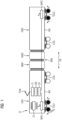
- FIG 1 shows schematically a rail vehicle, which is designed as an example as a multiple unit TZ for passenger transport.
- the multiple unit TZ comprises a plurality of cars, with a number of intermediate cars MW being arranged between a first end car EW1 and a second end car EW2 FIG 1 only two MW1, MW2 are shown in simplified form.
- the carriages are arranged one behind the other in the direction of travel FR and are mechanically connected to one another by means of suitable carriage couplings.
- Each of the cars has a car body WK, with all car bodies WK preferably providing at least one passenger compartment for passengers to stay.
- Car transitions are provided between the cars, over which passengers can move between adjacent cars or over the entire length of the multiple unit.
- the WK car bodies are each supported on bogies on rails of a track. Two bogies are arranged on each car body, for example, with adjacent car bodies WK alternatively also being able to be supported on a common so-called Jakobs bogie.
- the bogies are designed as motor bogies TDG with at least one driven wheel set or as trailer bogies LDG with only non-driven wheel sets.
- a motor bogie TDG1 or TDG2 each with two driven wheel sets and a respective trailer bogie LDG1 or LDG2 are arranged on the end cars EW1, EW2 of the multiple unit TZ.
- only trailer bogies are arranged on the middle cars EW1, EW2, which in the FIG 1 however, are not specifically illustrated.
- this can only include the two end cars EW1, EW2, to which the FIG 1 Motor bogies TDG1, TDG2 and trailer bogies LDG1, LDG2 are arranged, in turn, instead of the two trailer bogies LDG1, LDG2, a Jakobs bogie can be provided.
- the rail vehicle can also be designed as a locomotive whose car body is supported exclusively on motor bogies.
- Components of the electric drive system are indicated schematically in the end cars EW1, EW2 of the multiple unit TZ. These components are usually arranged in special areas within the car body WK, in the underfloor area, in the roof area or distributed over several cars. Other components of the drive system, such as one or more traction batteries or auxiliary systems required for the operation of the components and passenger comfort are in the FIG 1 however, not shown.
- the exemplary drive system of the multiple unit TZ can be electrically connected to an overhead line (not shown) of a railway supply network via a pantograph PAN arranged in the roof area of the first end car EW1, with the overhead line carrying a single-phase alternating current with a voltage of 15kV at 16.7Hz or 25kV at 50Hz.
- This alternating current is fed to a mains-side primary winding of a transformer TF, which transforms the mains-side voltage level down to a lower voltage level.
- a secondary winding of the transformer TF is connected to a line-side power converter, for example a rectifier GR or four-quadrant converter, which converts the AC voltage that is present into a DC voltage and feeds a DC voltage intermediate circuit ZK.
- the DC voltage intermediate circuit ZK is used according to the example FIG 1 a supply of two load-side converters, for example pulse-controlled inverters WR1, WR2, which convert the DC voltage of the DC voltage intermediate circuit ZK into a three-phase AC voltage of variable frequency and amplitude, with which the stator windings of the respective drive motors M in the motor bogies TDG1 and TDG2 are fed.
- the function, in particular of the power converters GR, WR1, WR2 is controlled, for example, by a central control device ST of the drive system.
- the drive system of the TZ multiple unit can alternatively or additionally be equipped with an overhead line or a power rail, which carries a direct current with a voltage level of, for example, 3kV or 1.5kV, can be electrically connected via a corresponding pantograph.
- the intermediate DC circuit ZK can be fed, for example, directly or via a DC converter, which converts the voltage level of the railway supply network to a desired voltage level of the intermediate DC circuit.
- the drive system of the multiple unit TZ can alternatively or additionally be supplied with electrical energy by means of one or more traction batteries and/or fuel cell systems, with the DC voltage intermediate circuit being fed in turn via a DC voltage converter, for example.
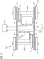
- FIG 2 additionally shows the structure of the first motor bogie TDG1 arranged on the first end car EW1, wherein the second motor bogie TDG2 on the second end car EW2 is preferably constructed identically.
- a bogie frame DGR of the first powered bogie TDG1 consists, for example, of a central crossbeam QT and two longitudinal beams LT arranged thereon, which together form the shape of a horizontal letter H.
- the first powered bogie TDG1 is rotatably and spring-loaded mechanically connected to the car body WK of the first end car EW1 via the bogie frame DGR.
- Two wheel sets RS are rotatably mounted in respective wheel set bearings on the side members LT, with each wheel set RS comprising a wheel set shaft RSW and two wheels R connected to it in a torsionally rigid manner.
- Two drive motors M1, M2 are suspended from the cross member QT of the bogie frame DGR, each of which is designed as a ventilated, permanent-magnet synchronous motor.
- the drive motors M1, M2 are arranged in accordance with a so-called transverse drive, in which the motor shaft is arranged parallel to the wheelset shaft and thus transversely to the direction of travel FR of the rail vehicle.
- the motor shafts of the drive motors M1, M2 are respectively connected via a switchable clutch K1, K2 to an input shaft of a transmission G supported on the wheelset shaft RSW, while the wheelset shaft RSW represents an output shaft of the transmission G.
- the transmission can be designed in one or more stages.
- the two drive motors M1, M2 each drive a wheel set RS via a clutch K1, K2 and a gearbox G.
- the clutches K1, K2 are designed, for example, as a so-called curved tooth clutch, which, due to its special design, can compensate for a certain relative offset between the motor shaft and the input shaft of the transmission G or between the motor M1, M2 and the wheel set RS in different planes .
- the respective clutch K1, K2 has, for example, one or more shifting elements SE, for example electromagnetic actuators, which are additionally arranged on the motor side of the curved tooth clutch or are integrated in it.
- These switching elements SE enable controlled switching or opening and closing of the respective clutch K1, K2, as a result of which an existing non-positive or positive connection between the motor shaft and the input shaft of the transmission can be separated or restored.
- the shifting elements SE are preferably designed not only to be able to be opened in a controlled manner under load, i.e. during torque transmission, but also to be able to be closed again while the multiple unit TZ is being driven, i.e. when the input shaft of the transmission G is rotating.
- the clutches K1, K2 are thus designed, for example, as curved tooth clutches, each with an integrated clutch.
- the switching elements SE are controlled by the central control device ST, as is shown in FIGS FIG 1 and 2 using the dotted arrows or lines is given by way of example, with control signal paths between the control device ST and the clutches K1, K2 or the converters WR1, WR2 in FIG FIG 1 are not shown in full for reasons of clarity.
- the control device ST switches the clutches K1, K2, in particular depending on a function of the drive motors M1, M2, in order to ensure the required safety of drive motors excited by permanent magnets in relation to the surroundings or the environment.
- the state of the drive motors M1, M2 is monitored using suitable sensors that are arranged on or in the vicinity of the drive motors M1, M2.
- suitable sensors that are arranged on or in the vicinity of the drive motors M1, M2.
- this can be temperature sensors, vibration sensors and current sensors. Signals provided by these sensors, in particular during operation of the multiple unit TZ, are evaluated in the control device ST or, for example, in an upstream evaluation device, and in the control device ST with regard to the presence of a fault, for example the presence of a short circuit in the stator winding or damage to a roller bearing of the motor shaft , rated.
- the control device ST controls the first clutch K1 of the first drive motor M1 that has been detected as faulty, so that it is opened and the existing mechanical connection of the first drive motor M1 is separated from the axle RSW driven by this.
- the control device ST also controls the first power converter WR1.
- control device ST blocks the power semiconductor switches of the first converter WR1, which are used to convert the DC voltage of the DC voltage intermediate circuit ZK into a three-phase AC voltage of variable voltage level and frequency, so that no more current flows into the stator winding of the faulty first drive motor M1.
- the first converter WR1 or a converter circuit in the first converter WR1 feeds both drive motors M1, M2 in the first motor bogie TDG1 in parallel.
- a blocking of the first converter WR1 by the control device ST thus means that the second drive motor M2, which is fault-free or was not detected as faulty, is no longer fed by the first converter WR1.
- the control device ST also controls the second clutch K2 so that the second drive motor M2 also operates from the this driven axle RSW is separated.
- the detection of an exemplary faulty first drive motor M1 in the first motor bogie TDG1 thus results in both drive motors M1, M2 of the first motor bogie TDG1 are separated from their driven wheelsets RS, which only a maximum of half of the total drive power is available for operating the TZ multiple unit.
- the driving operation of the multiple unit TZ can be maintained or the multiple unit TZ can be moved at least to a next stopping station according to the given route plan.
- each of the drive motors of the motor bogies is fed by a separate converter or by a separate converter circuit of the converter, all fault-free drive motors can continue to be operated, so that the multiple unit continues to have maximum power in the event of a faulty drive motor three quarters of the total drive power is available.
- all fault-free drive motors can continue to be operated, so that the multiple unit continues to have maximum power in the event of a faulty drive motor three quarters of the total drive power is available.
- the control device ST controls the clutches K1, K2 in the first motor bogie TDG1 additionally depending on a function of the first converter WR1, the state of the first converter WR1 being monitored accordingly by means of suitable sensors. If a fault, for example a short circuit in a power semiconductor switch of the first power converter WR1, is detected by the control device ST from signals from the sensors, the control device ST not only blocks the power semiconductor switch of the first power converter WR1, but also controls the clutches K1, K2 so that they be opened.
- the existing mechanical connections between the drive motors M1, M2 and the wheel set axles RSW of the first motor bogie TDG1 are separated, thereby preventing a current flow into the faulty first converter WR1 due to generator operation of the drive motors M1, M2 and thus possible further damage to the first converter WR1.
- the faulty first power converter WR1 can be electrically insulated to the greatest possible extent by blocking and opening the clutches K1, K2 of the supplied drive motors M1, M2, thereby avoiding possible damage to other components of the drive system.
- the driving operation of the multiple unit TZ can continue to be maintained by means of the second inverter WR2 and the drive motors fed by it.
- controlling the clutches K1, K2 by the control device ST can serve not only to protect the drive motors and the surroundings or the environment in the event of a detected fault, but also to actively control the drive system or the drive power in order to make it as energy-efficient as possible operate.
- the clutches K1, K2 in the first powered bogie TDG1 can be opened and, if necessary, closed again depending on a phase of movement described in the introduction, in which the multiple unit TZ is located.
- the clutches K1, K2 are designed in such a way that they can be both opened and closed while the multiple unit TZ is in operation, i.e. when it is not stationary at a stopping station, for example, in order to use the drive power as well as the generator power of the drive motors M1, M2 to be able to optimally control according to the respective requirements of the movement phases.
- the following sequence of movement phases corresponds to a typical driving game between two stopping stations, referred to by way of example as starting stopping station and destination stopping station, at one to be traveled over by the multiple unit TZ Route.
- the multiple unit TZ Starting from a standstill at the start/stop station, the multiple unit TZ initially accelerates to a specific speed in an acceleration phase, with both the speed and a value to be achieved for the acceleration being specified. Accelerating and reaching the specified speed usually requires a maximum or almost maximum traction of the drive motors of the drive system, so that in the acceleration phase all clutches are initially closed and all drive motors in the motor bogies TDG1, TDG2 are fed by the converters WR1, WR2.
- the acceleration phase or after the predetermined speed has been reached is usually followed by an inertia phase in which the speed reached is kept largely constant over a specific time or distance. Maintaining the speed usually requires a significantly lower tractive force than the previous acceleration, which only has to compensate for the driving resistance force. If the drive system continues to feed all traction motors in this phase, they are only operated at partial load and therefore with poorer efficiency.
- the control device ST controls the clutches K1, K2, so that the drive motors M1, M2 of the first powered bogie TDG1 are separated from the wheelsets RS.
- control device ST also blocks the first power converter WR1 so that it no longer feeds the drive motors M1, M2.
- the multiple unit TZ is now driven exclusively by the second power converter WR1 and the drive motors of the second powered bogie TDG2, which, however, are operated in a higher and therefore more efficient load range.
- the drive motors M1, M2 of the first powered bogie TDG1 come to a standstill, so that there are no longer any losses due to forced running.
- the first power converter WR1 can be controlled periodically by the control device ST, for example, in such a way that the feeding currents cause the motor shafts to rotate at a low speed.
- the inertia phase is usually followed by a rolling phase, in which the traction force is reduced to zero, so that the speed of the multiple unit TZ decreases continuously due to the then prevailing driving resistance force.
- the control device ST could in principle also separate the drive motors of the second powered bogie TDG2 from the driven wheelsets by opening the corresponding clutches.
- the clutches of the second motor bogie TDG2 are kept closed.
- the rolling phase is usually followed by a braking phase, in which the speed is further reduced to such an extent that the multiple unit TZ comes to a standstill at the destination stopping station in order to enable passengers to get on and off at this station.
- the provision of a braking force that supplements the driving resistance force that decreases with speed is preferably carried out exclusively or predominantly by operating the drive motors as generators, as a result of which kinetic energy of the multiple unit TZ can be converted into electrical energy and a braking torque can thereby be generated.
- Such a regenerative braking advantageously reduces the wear of friction brakes of the multiple unit TZ.
- the drive motors M1, M2 of the first powered bogie TDG1 were separated from the wheelset axles RSW during the stagnation phase by the controlled opening of the clutches K1, K2, they cannot be operated as generators and therefore cannot provide any additional braking torque. If the clutches K1, K2 are configured during driving, i.e. in particular in a braking phase of the Driving game, to be able to be closed again, these are preferably controlled accordingly by the control device ST in order to also operate the drive motors M1, M2 of the first powered bogie TDG1 as generators to provide a braking torque.
- control device ST can control the first power converter WR1, for example on the basis of a speed of the wheelset shafts or transmission input shafts determined by means of speed sensors, in such a way that the motor shafts of the drive motors M1, M2 rotate at the same or almost the same speed in order to ensure that the clutches K1 , to ensure K2.
- Previously opened clutches K1, K2 can also be closed, for example, if an inertia phase or a rolling phase is followed by another acceleration phase, in which a higher tractive force than that provided by the motors of the second motor bogie TDG2 is required.
- the clutches K1, K2 of the first motor bogie TDG1 can also be closed again accordingly in the event of an acceleration requested by the train driver, for example, in order to be able to provide a traction force that is sufficient for the request.
- An opening and closing of the clutches K1, K2 can therefore also take place depending on, for example, a load or loading of the multiple unit TZ.
- the clutches K1, K2 in the first powered bogie TDG1 must be open and the first power converter WR1 blocked, so that the multiple power train TZ is driven exclusively by means of the second power converter WR2 and the second powered bogie TDG2.
Landscapes
- Engineering & Computer Science (AREA)
- Transportation (AREA)
- Mechanical Engineering (AREA)
- Life Sciences & Earth Sciences (AREA)
- Sustainable Development (AREA)
- Sustainable Energy (AREA)
- Power Engineering (AREA)
- Chemical & Material Sciences (AREA)
- Combustion & Propulsion (AREA)
- Electric Propulsion And Braking For Vehicles (AREA)
Applications Claiming Priority (1)
| Application Number | Priority Date | Filing Date | Title |
|---|---|---|---|
| DE102021208388.9A DE102021208388A1 (de) | 2021-08-03 | 2021-08-03 | Antriebssystem für ein Schienenfahrzeug |
Publications (1)
| Publication Number | Publication Date |
|---|---|
| EP4129744A1 true EP4129744A1 (fr) | 2023-02-08 |
Family
ID=82781134
Family Applications (1)
| Application Number | Title | Priority Date | Filing Date |
|---|---|---|---|
| EP22187457.1A Pending EP4129744A1 (fr) | 2021-08-03 | 2022-07-28 | Système d'entraînement pour un véhicule ferroviaire |
Country Status (2)
| Country | Link |
|---|---|
| EP (1) | EP4129744A1 (fr) |
| DE (1) | DE102021208388A1 (fr) |
Citations (5)
| Publication number | Priority date | Publication date | Assignee | Title |
|---|---|---|---|---|
| EP2301789A2 (fr) * | 2009-09-24 | 2011-03-30 | Siemens Aktiengesellschaft | Véhicule sur rails doté d'entraînements de roue individuels |
| DE102010040491A1 (de) * | 2010-09-09 | 2012-03-15 | Siemens Aktiengesellschaft | Fahrmotor mit Kühlung |
| DE102015215576A1 (de) | 2015-08-14 | 2017-02-16 | Siemens Aktiengesellschaft | Traktionsantrieb mit mechanischer Entkopplung |
| EP3185403A1 (fr) * | 2015-12-23 | 2017-06-28 | Siemens Aktiengesellschaft | Machine synchrone a excitation permanente comprenant un couplage automatique de rotors dans un court-circuit d'enroulement |
| EP3564088A1 (fr) | 2018-05-02 | 2019-11-06 | Siemens Aktiengesellschaft | Système d'entraînement pour un véhicule sur rail |
Family Cites Families (1)
| Publication number | Priority date | Publication date | Assignee | Title |
|---|---|---|---|---|
| DE102019109971A1 (de) | 2019-04-16 | 2020-10-22 | Voith Patent Gmbh | Antriebsstrang für ein Schienenfahrzeug |
-
2021
- 2021-08-03 DE DE102021208388.9A patent/DE102021208388A1/de not_active Withdrawn
-
2022
- 2022-07-28 EP EP22187457.1A patent/EP4129744A1/fr active Pending
Patent Citations (5)
| Publication number | Priority date | Publication date | Assignee | Title |
|---|---|---|---|---|
| EP2301789A2 (fr) * | 2009-09-24 | 2011-03-30 | Siemens Aktiengesellschaft | Véhicule sur rails doté d'entraînements de roue individuels |
| DE102010040491A1 (de) * | 2010-09-09 | 2012-03-15 | Siemens Aktiengesellschaft | Fahrmotor mit Kühlung |
| DE102015215576A1 (de) | 2015-08-14 | 2017-02-16 | Siemens Aktiengesellschaft | Traktionsantrieb mit mechanischer Entkopplung |
| EP3185403A1 (fr) * | 2015-12-23 | 2017-06-28 | Siemens Aktiengesellschaft | Machine synchrone a excitation permanente comprenant un couplage automatique de rotors dans un court-circuit d'enroulement |
| EP3564088A1 (fr) | 2018-05-02 | 2019-11-06 | Siemens Aktiengesellschaft | Système d'entraînement pour un véhicule sur rail |
Also Published As
| Publication number | Publication date |
|---|---|
| DE102021208388A1 (de) | 2023-02-09 |
Similar Documents
| Publication | Publication Date | Title |
|---|---|---|
| EP0730539B1 (fr) | Vehicule automoteur roulant sur rails | |
| DE202009014490U1 (de) | Antriebssystem | |
| US8188692B2 (en) | Propulsion system | |
| EP3584107A1 (fr) | Interconnexion des véhicules et procédé d'alimentation d'un réseau embarqué électrique dans une telle interconnexion | |
| WO2020069737A1 (fr) | Système de freinage pour un véhicule ferroviaire | |
| DE102013223409A1 (de) | Elektro-mechanischer Hybridantrieb und Fahrzeug | |
| EP3564088B1 (fr) | Véhicule sur rail avec système d'entraînement | |
| EP4129744A1 (fr) | Système d'entraînement pour un véhicule ferroviaire | |
| CN210578241U (zh) | 永磁牵引变流器主电路、永磁牵引系统及车辆牵引系统 | |
| EP3150420A1 (fr) | Groupes d'entrainement pour vehicules | |
| EP3630571B1 (fr) | Système de transport à traction par câble et procédé pour faire fonctionner ce système | |
| EP4063175A1 (fr) | Procédé de fonctionnement d'un véhicule ferroviaire et véhicule ferroviaire | |
| DE19860618C1 (de) | Elektrische Antriebsmaschinenbaueinheit | |
| Kurz | Rolling across Europe's vanishing frontiers [electric railway technology] | |
| EP4219216A1 (fr) | Procédé de fonctionnement d'un véhicule à propulsion électrique et véhicule à propulsion électrique | |
| DE102009050145A1 (de) | Elektrischer Fahrantrieb eines mittels Achslagern auf mindestens zwei auf Schienen verfahrbaren Radsätzen gelagerten Güterwagens | |
| WO2023134914A1 (fr) | Procédé de commande d'un système d'entraînement d'un véhicule ferroviaire | |
| EP3594081A1 (fr) | Système d'entraînement pour un véhicule sur rail | |
| DE102015215576A1 (de) | Traktionsantrieb mit mechanischer Entkopplung | |
| EP4112356A1 (fr) | Dispositif d'alimentation en énergie d'un dispositif capteur dans un véhicule ferroviaire | |
| DE102022206679A1 (de) | Elektrisches Antriebssystem | |
| DE102022001110A1 (de) | Hybrid-Antriebseinheit | |
| DE102022114472A1 (de) | Axialflussmaschine, elektrischer Achsantriebsstrang und Kraftfahrzeug | |
| WO2023151754A1 (fr) | Machine à flux axial, chaîne cinématique à essieu électrique et véhicule à moteur | |
| DE1438978C3 (de) | Stromversorgungseinrichtung für die Hilfsbetriebe eines von einem Verbrennungsmotor angetriebenen Schienentriebfahrzeuges |
Legal Events
| Date | Code | Title | Description |
|---|---|---|---|
| PUAI | Public reference made under article 153(3) epc to a published international application that has entered the european phase |
Free format text: ORIGINAL CODE: 0009012 |
|
| STAA | Information on the status of an ep patent application or granted ep patent |
Free format text: STATUS: THE APPLICATION HAS BEEN PUBLISHED |
|
| AK | Designated contracting states |
Kind code of ref document: A1 Designated state(s): AL AT BE BG CH CY CZ DE DK EE ES FI FR GB GR HR HU IE IS IT LI LT LU LV MC MK MT NL NO PL PT RO RS SE SI SK SM TR |
|
| STAA | Information on the status of an ep patent application or granted ep patent |
Free format text: STATUS: REQUEST FOR EXAMINATION WAS MADE |
|
| 17P | Request for examination filed |
Effective date: 20230803 |
|
| RBV | Designated contracting states (corrected) |
Designated state(s): AL AT BE BG CH CY CZ DE DK EE ES FI FR GB GR HR HU IE IS IT LI LT LU LV MC MK MT NL NO PL PT RO RS SE SI SK SM TR |