EP4129731A1 - Fastener and shield unit - Google Patents
Fastener and shield unit Download PDFInfo
- Publication number
- EP4129731A1 EP4129731A1 EP21775167.6A EP21775167A EP4129731A1 EP 4129731 A1 EP4129731 A1 EP 4129731A1 EP 21775167 A EP21775167 A EP 21775167A EP 4129731 A1 EP4129731 A1 EP 4129731A1
- Authority
- EP
- European Patent Office
- Prior art keywords
- spring
- shield member
- fastener
- sleeve
- flange
- Prior art date
- Legal status (The legal status is an assumption and is not a legal conclusion. Google has not performed a legal analysis and makes no representation as to the accuracy of the status listed.)
- Pending
Links
- 230000000694 effects Effects 0.000 abstract description 7
- 238000010521 absorption reaction Methods 0.000 abstract description 3
- 230000035939 shock Effects 0.000 abstract description 3
- 230000003139 buffering effect Effects 0.000 description 12
- 239000012212 insulator Substances 0.000 description 9
- 230000005540 biological transmission Effects 0.000 description 6
- 239000002184 metal Substances 0.000 description 3
- 238000004519 manufacturing process Methods 0.000 description 2
- 230000015572 biosynthetic process Effects 0.000 description 1
- 238000006073 displacement reaction Methods 0.000 description 1
- 230000012447 hatching Effects 0.000 description 1
- 230000000149 penetrating effect Effects 0.000 description 1
- 238000003786 synthesis reaction Methods 0.000 description 1
Images


Classifications
-
- F—MECHANICAL ENGINEERING; LIGHTING; HEATING; WEAPONS; BLASTING
- F16—ENGINEERING ELEMENTS AND UNITS; GENERAL MEASURES FOR PRODUCING AND MAINTAINING EFFECTIVE FUNCTIONING OF MACHINES OR INSTALLATIONS; THERMAL INSULATION IN GENERAL
- F16B—DEVICES FOR FASTENING OR SECURING CONSTRUCTIONAL ELEMENTS OR MACHINE PARTS TOGETHER, e.g. NAILS, BOLTS, CIRCLIPS, CLAMPS, CLIPS OR WEDGES; JOINTS OR JOINTING
- F16B5/00—Joining sheets or plates, e.g. panels, to one another or to strips or bars parallel to them
- F16B5/02—Joining sheets or plates, e.g. panels, to one another or to strips or bars parallel to them by means of fastening members using screw-thread
- F16B5/0266—Joining sheets or plates, e.g. panels, to one another or to strips or bars parallel to them by means of fastening members using screw-thread using springs
-
- F—MECHANICAL ENGINEERING; LIGHTING; HEATING; WEAPONS; BLASTING
- F01—MACHINES OR ENGINES IN GENERAL; ENGINE PLANTS IN GENERAL; STEAM ENGINES
- F01N—GAS-FLOW SILENCERS OR EXHAUST APPARATUS FOR MACHINES OR ENGINES IN GENERAL; GAS-FLOW SILENCERS OR EXHAUST APPARATUS FOR INTERNAL COMBUSTION ENGINES
- F01N13/00—Exhaust or silencing apparatus characterised by constructional features ; Exhaust or silencing apparatus, or parts thereof, having pertinent characteristics not provided for in, or of interest apart from, groups F01N1/00 - F01N5/00, F01N9/00, F01N11/00
- F01N13/08—Other arrangements or adaptations of exhaust conduits
- F01N13/10—Other arrangements or adaptations of exhaust conduits of exhaust manifolds
- F01N13/102—Other arrangements or adaptations of exhaust conduits of exhaust manifolds having thermal insulation
-
- B—PERFORMING OPERATIONS; TRANSPORTING
- B60—VEHICLES IN GENERAL
- B60K—ARRANGEMENT OR MOUNTING OF PROPULSION UNITS OR OF TRANSMISSIONS IN VEHICLES; ARRANGEMENT OR MOUNTING OF PLURAL DIVERSE PRIME-MOVERS IN VEHICLES; AUXILIARY DRIVES FOR VEHICLES; INSTRUMENTATION OR DASHBOARDS FOR VEHICLES; ARRANGEMENTS IN CONNECTION WITH COOLING, AIR INTAKE, GAS EXHAUST OR FUEL SUPPLY OF PROPULSION UNITS IN VEHICLES
- B60K13/00—Arrangement in connection with combustion air intake or gas exhaust of propulsion units
- B60K13/04—Arrangement in connection with combustion air intake or gas exhaust of propulsion units concerning exhaust
-
- F—MECHANICAL ENGINEERING; LIGHTING; HEATING; WEAPONS; BLASTING
- F01—MACHINES OR ENGINES IN GENERAL; ENGINE PLANTS IN GENERAL; STEAM ENGINES
- F01N—GAS-FLOW SILENCERS OR EXHAUST APPARATUS FOR MACHINES OR ENGINES IN GENERAL; GAS-FLOW SILENCERS OR EXHAUST APPARATUS FOR INTERNAL COMBUSTION ENGINES
- F01N13/00—Exhaust or silencing apparatus characterised by constructional features ; Exhaust or silencing apparatus, or parts thereof, having pertinent characteristics not provided for in, or of interest apart from, groups F01N1/00 - F01N5/00, F01N9/00, F01N11/00
- F01N13/08—Other arrangements or adaptations of exhaust conduits
-
- F—MECHANICAL ENGINEERING; LIGHTING; HEATING; WEAPONS; BLASTING
- F01—MACHINES OR ENGINES IN GENERAL; ENGINE PLANTS IN GENERAL; STEAM ENGINES
- F01N—GAS-FLOW SILENCERS OR EXHAUST APPARATUS FOR MACHINES OR ENGINES IN GENERAL; GAS-FLOW SILENCERS OR EXHAUST APPARATUS FOR INTERNAL COMBUSTION ENGINES
- F01N13/00—Exhaust or silencing apparatus characterised by constructional features ; Exhaust or silencing apparatus, or parts thereof, having pertinent characteristics not provided for in, or of interest apart from, groups F01N1/00 - F01N5/00, F01N9/00, F01N11/00
- F01N13/14—Exhaust or silencing apparatus characterised by constructional features ; Exhaust or silencing apparatus, or parts thereof, having pertinent characteristics not provided for in, or of interest apart from, groups F01N1/00 - F01N5/00, F01N9/00, F01N11/00 having thermal insulation
-
- F—MECHANICAL ENGINEERING; LIGHTING; HEATING; WEAPONS; BLASTING
- F01—MACHINES OR ENGINES IN GENERAL; ENGINE PLANTS IN GENERAL; STEAM ENGINES
- F01N—GAS-FLOW SILENCERS OR EXHAUST APPARATUS FOR MACHINES OR ENGINES IN GENERAL; GAS-FLOW SILENCERS OR EXHAUST APPARATUS FOR INTERNAL COMBUSTION ENGINES
- F01N13/00—Exhaust or silencing apparatus characterised by constructional features ; Exhaust or silencing apparatus, or parts thereof, having pertinent characteristics not provided for in, or of interest apart from, groups F01N1/00 - F01N5/00, F01N9/00, F01N11/00
- F01N13/18—Construction facilitating manufacture, assembly, or disassembly
- F01N13/1805—Fixing exhaust manifolds, exhaust pipes or pipe sections to each other, to engine or to vehicle body
-
- F—MECHANICAL ENGINEERING; LIGHTING; HEATING; WEAPONS; BLASTING
- F16—ENGINEERING ELEMENTS AND UNITS; GENERAL MEASURES FOR PRODUCING AND MAINTAINING EFFECTIVE FUNCTIONING OF MACHINES OR INSTALLATIONS; THERMAL INSULATION IN GENERAL
- F16B—DEVICES FOR FASTENING OR SECURING CONSTRUCTIONAL ELEMENTS OR MACHINE PARTS TOGETHER, e.g. NAILS, BOLTS, CIRCLIPS, CLAMPS, CLIPS OR WEDGES; JOINTS OR JOINTING
- F16B39/00—Locking of screws, bolts or nuts
- F16B39/22—Locking of screws, bolts or nuts in which the locking takes place during screwing down or tightening
- F16B39/24—Locking of screws, bolts or nuts in which the locking takes place during screwing down or tightening by means of washers, spring washers, or resilient plates that lock against the object
-
- F—MECHANICAL ENGINEERING; LIGHTING; HEATING; WEAPONS; BLASTING
- F16—ENGINEERING ELEMENTS AND UNITS; GENERAL MEASURES FOR PRODUCING AND MAINTAINING EFFECTIVE FUNCTIONING OF MACHINES OR INSTALLATIONS; THERMAL INSULATION IN GENERAL
- F16B—DEVICES FOR FASTENING OR SECURING CONSTRUCTIONAL ELEMENTS OR MACHINE PARTS TOGETHER, e.g. NAILS, BOLTS, CIRCLIPS, CLAMPS, CLIPS OR WEDGES; JOINTS OR JOINTING
- F16B43/00—Washers or equivalent devices; Other devices for supporting bolt-heads or nuts
-
- F—MECHANICAL ENGINEERING; LIGHTING; HEATING; WEAPONS; BLASTING
- F16—ENGINEERING ELEMENTS AND UNITS; GENERAL MEASURES FOR PRODUCING AND MAINTAINING EFFECTIVE FUNCTIONING OF MACHINES OR INSTALLATIONS; THERMAL INSULATION IN GENERAL
- F16B—DEVICES FOR FASTENING OR SECURING CONSTRUCTIONAL ELEMENTS OR MACHINE PARTS TOGETHER, e.g. NAILS, BOLTS, CIRCLIPS, CLAMPS, CLIPS OR WEDGES; JOINTS OR JOINTING
- F16B5/00—Joining sheets or plates, e.g. panels, to one another or to strips or bars parallel to them
- F16B5/02—Joining sheets or plates, e.g. panels, to one another or to strips or bars parallel to them by means of fastening members using screw-thread
-
- F—MECHANICAL ENGINEERING; LIGHTING; HEATING; WEAPONS; BLASTING
- F01—MACHINES OR ENGINES IN GENERAL; ENGINE PLANTS IN GENERAL; STEAM ENGINES
- F01N—GAS-FLOW SILENCERS OR EXHAUST APPARATUS FOR MACHINES OR ENGINES IN GENERAL; GAS-FLOW SILENCERS OR EXHAUST APPARATUS FOR INTERNAL COMBUSTION ENGINES
- F01N2450/00—Methods or apparatus for fitting, inserting or repairing different elements
- F01N2450/24—Methods or apparatus for fitting, inserting or repairing different elements by bolts, screws, rivets or the like
-
- F—MECHANICAL ENGINEERING; LIGHTING; HEATING; WEAPONS; BLASTING
- F16—ENGINEERING ELEMENTS AND UNITS; GENERAL MEASURES FOR PRODUCING AND MAINTAINING EFFECTIVE FUNCTIONING OF MACHINES OR INSTALLATIONS; THERMAL INSULATION IN GENERAL
- F16B—DEVICES FOR FASTENING OR SECURING CONSTRUCTIONAL ELEMENTS OR MACHINE PARTS TOGETHER, e.g. NAILS, BOLTS, CIRCLIPS, CLAMPS, CLIPS OR WEDGES; JOINTS OR JOINTING
- F16B39/00—Locking of screws, bolts or nuts
- F16B39/22—Locking of screws, bolts or nuts in which the locking takes place during screwing down or tightening
- F16B39/24—Locking of screws, bolts or nuts in which the locking takes place during screwing down or tightening by means of washers, spring washers, or resilient plates that lock against the object
- F16B39/26—Locking of screws, bolts or nuts in which the locking takes place during screwing down or tightening by means of washers, spring washers, or resilient plates that lock against the object with spring washers fastened to the nut or bolt-head
-
- F—MECHANICAL ENGINEERING; LIGHTING; HEATING; WEAPONS; BLASTING
- F16—ENGINEERING ELEMENTS AND UNITS; GENERAL MEASURES FOR PRODUCING AND MAINTAINING EFFECTIVE FUNCTIONING OF MACHINES OR INSTALLATIONS; THERMAL INSULATION IN GENERAL
- F16B—DEVICES FOR FASTENING OR SECURING CONSTRUCTIONAL ELEMENTS OR MACHINE PARTS TOGETHER, e.g. NAILS, BOLTS, CIRCLIPS, CLAMPS, CLIPS OR WEDGES; JOINTS OR JOINTING
- F16B5/00—Joining sheets or plates, e.g. panels, to one another or to strips or bars parallel to them
- F16B5/02—Joining sheets or plates, e.g. panels, to one another or to strips or bars parallel to them by means of fastening members using screw-thread
- F16B5/0258—Joining sheets or plates, e.g. panels, to one another or to strips or bars parallel to them by means of fastening members using screw-thread using resiliently deformable sleeves, grommets or inserts
Definitions
- the present invention relates to a fastener to fasten a shield member to a structure. Also, the present invention relates to a shield unit that includes the shield member and the fastener.
- the fastener in the patent document 1 includes a support component to fasten a shield member such as a heat insulator or the like to a structure such as an exhaust manifold or the like, and bolts.
- the support component has a cylindrical body penetrating through a hole made in the heat insulator, a washer fitted to one end of the tube body, a flange formed in the other one end of the cylindrical body, and elastic bodies which are secured between the washer and the heat insulator and between the lange and the heat insulator, respectively.
- the bolt is screwed into fastening target sections of the exhaust manifold, through the cylindrical body of the support. Accordingly, the heat insulator is fastened to the exhaust manifold.
- Patent Document 1 Patent No. 5885258 Gazette
- the problem to be solved by the present invention is to provide a fastener from which the sufficient buffering effect can be obtained and a shield unit.
- a fastener in the present invention is a fastener for fastening a shield member to a structure, and comprises: a support part for supporting the shield member, and a fixing component for fixing the shield member through the support component to the structure, wherein the support part has: a cylindrical part which is inserted into a hole provided in the shield member and into which the fixing component is inserted; two flange parts which are each provided at both ends of the cylindrical part and opposite to each other on both sides of the shield member; and spring parts which are interposed between each of the two flange parts and both sides of the shield member, and wherein the spring parts have a first spring and a second spring with different load -deflection characteristic, the first spring is interposed between each of the two flange parts and the both sides of the shield member, and the second spring is interposed between at least one of the two flange parts and at least one of the both sides of the shield member.
- the cylindrical part and the two flange parts are configured by: a sleeve in which a flange part is integrally provided at one end, and a ring fitted to the other end of the sleeve,
- the first spring is composed of: a sleeve-shaped spring in which a flange is integrally provided at one end and a ring-shaped spring fitted to the other end of the sleeve-shaped spring, the sleeve-shaped spring is inserted into the hole of the shield member and fitted to the sleeve from outside, the flange of the sleeve-shaped spring is interposed between one of the two flange parts and one of the both sides of the shield member, and the ring-shaped spring is interposed between the other of the two flange parts and the other of the both sides of the shield member.
- the support component has interposing parts which are each interposed between the both sides of the shield member and the spring part.
- the first spring is a spring configured by wire mesh
- the second spring is a wave washer
- a shield unit comprises: a shield member for shielding a structure from transmitting its influence to surroundings; and the fastener in the present invention, wherein the shielding member has a hole into which the cylindrical part of the fastener is inserted.
- the fastener and the shielding unit according to the present invention provide a sufficient buffering effect.
- the shield unit 1 includes a shield member (an insulator, a heat insulator or the like) 2, and the fastener 3 according to this embodiment.
- the shield member 2 is a metal member and configured by a metal cover member, a metal plate member and others.
- the shield member 2 shields an influence of a structure 4 from being transmitted to surroundings. That is, the shield member 2 protects the components, devices, members and others around the structure 4 from the influence of the structure 4.
- the structure 4 is, for example, an exhaust manifold, an outlet pipe of a turbine and the like. As the influence of the structure 4, for example, there are heat, sound and others generated in the structure 4.
- a fixing boss part 40 as a fixing part is integrally provided at a location to which the shield member 2 is fixed.
- a screw hole 41 is provided at the fixing boss part 40.
- a hole 20 is provided at a location corresponding to the fixing boss part 40.
- the hole 20 is circular in shape.
- a cylindrical part 61 of a sleeve 6 in the fastener 3 is inserted into this hole 20.
- the holes 20 of the shielding member 2 and the fixing boss part 40 of the structure 4 are provided four each in this example.
- the number and locations of the holes 20 and the fixing boss parts 40 are not limited to this example.
- the fastener 3 includes a support component 5, and a bolt 50 as a fixing component.
- the support component 5 supports the shield member 2.
- the bolt 50 fix the shield member 2 to the structure 4 via the support component.
- the support component 5 has the sleeve 6 and a ring 60, a first spring 7 and a second spring 8 which serve as spring parts, and two washers (dish washers) 9 as interposing parts.
- the sleeve 6 has the cylindrical part 61 and a flange part 62.
- An inner diameter of the cylindrical part 61 is approximately equal to an inner diameter of the screw hole 41 in the fixing boss part 40.
- the cylindrical part 61 is inserted into the hole 20 in the shield member 2.
- the bolt 50 is inserted into the cylindrical part 61.
- the flange part 62 is integrally provided at one end (lower end) of the cylindrical part 61.
- An engagement groove 63 is provided in a circumferential direction on an outer circumference surface of the other end (upper end) of the cylindrical part 61.
- an engaging convex part 64 engaged in the engagement groove 63 is provided in the circumferential direction on an inner circumference surface of the ring 60 as a flange part.
- the first spring 7 as the spring part is the spring configured by wire mesh, in this example.
- the second spring 8 as the spring part is the spring configured by two wave washers, in this example.
- a load -deflection (displacement) characteristic of a spring in Fig. 5 a load -deflection characteristic of the first spring 7 (a curve A in Fig. 5 ) and a load-deflection characteristic of the second spring 8 (a curve B in Fig. 5 ) differ from each other.
- the first spring 7 is composed of a sleeve-shaped spring 70 and a ring-shaped spring 71.
- the sleeve-shaped spring 70 is cylindrical in shape, and a flange 72 is integrally provided at one end (lower end).
- An inner diameter of the sleeve-shaped spring 70 that is cylindrical in shape is approximately equal to or slightly larger than an outer diameter of the cylindrical part 61 of the sleeve 6.
- An inner diameter of the ring-shaped spring 71 is approximately equal to or slightly smaller than an outer diameter of the other end (upper end) of the sleeve-shaped spring 70.
- the ring-shaped spring 71 is fitted to the other end of the sleeve-shaped spring 70.
- the two washers 9 are each applied to both sides (upper and lower sides) of the location at which the hole 20 is provided and arranged there.
- the second springs 8 of two wave washers is placed in contact with two washers 9, the upper and lower, respectively.
- the sleeve-shaped spring 70 of the first spring 7 is inserted from below into through holes of the two second springs 8, through holes of the two washers 9 and the hole 20 of the shield member 2.
- the flange 72 of this sleeve-shaped spring 70 is placed in contact with the second spring 8 of the lower wave washer.
- the ring-shaped spring 71 of the first spring 7 is fitted from outside to the other end (upper end) of this sleeve-shaped spring 70. This ring-shaped spring 71 is placed in contact with the second spring 8 of the upper wave washer.
- the cylindrical part 61 of the sleeve 6 is inserted from below into the sleeve-shaped spring 70.
- the flange part 62 of this sleeve 6 is placed against the flange 72 of the sleeve-shaped spring 70 from below.
- the engaging convex part 64 of the ring 60 is fitted from outside to the engagement groove 63 of this sleeve 6. Accordingly, the support component 5 of the fastener 3 is assembled to the shield member 2.
- the cylindrical part namely, the cylindrical part 61 of the sleeve 6 is inserted into the hole 20 of the shield member 2.
- the two flange parts namely, the flange part 62 of the sleeve 6 and the ring 60 as the flange part are opposite to each other on both sides (upper and lower sides) of the shield member 2.
- the spring parts namely, the first springs 7 and the second springs 8 are each interposed between the two flange parts, namely, the flange part 62 of the sleeve 6 and the ring 60 as the flange part, and the both sides (upper and lower sides) of the shield member 2, through the upper and lower two washers 9.
- the sleeve-shaped spring 70 of the first spring 7 is fitted from outside to the sleeve 6, namely, the cylindrical part 61 of the sleeve 6.
- the flange 72 of the sleeve-shaped spring 70 in the first spring 7 is interposed between one of the two flange parts, namely, the flange part 62 of the sleeve 6 and one of the both sides of the shield member 2, namely, the lower side, through the lower washer 9.
- the ring-shaped spring 71 of the first spring 7 is interposed between the other one of the two flange parts, namely, the ring 60 as the flange part, and the other side of the both sides of the shield member 2, namely, the upper side, through the upper washer 9.
- the upper and lower two washers 9 as the interposing parts are interposed between the both sides (upper and lower sides) of the shield member 2, and the second spring 8 of the upper and lower two wave washers.
- the structure 4 is covered by the shield member 2.
- the support component 5 in the fastener 3 assembled to the shield member 2 is positioned at the fixing boss part 40 of the structure 4.
- a hollow part of the cylindrical part 61 in the support component 5 is positionally matched with the screw hole 41 of the fixing boss part 40.
- the screw part of the bolt 50 in the fastener 3 is inserted into the cylindrical part 61 and screwed into the screw hole 41 of the fixing boss part 40.
- the support component 5 is sandwiched and secured between a head part of the bolt 50 and the fixing boss part 40. Consequently, the shield member 2 is fastened to the structure 4, through the support component 5 and bolt 50 in the fastener 3.
- the fastener 3 and shield unit 1 according to this embodiment are structured by the foregoing configuration. Their actions will be explained below.
- the shield member 2 is fastened to the structure 4 by the fastener 3 in a situation in which the structure 4 is covered. Accordingly, the shield member 2 shields the heat, sound and others generated in the structure 4. As a result, the shield member 2 protects the components, devices, members and others around the structure 4 from being inflected by the heat, sound and others generated in the structure 4.
- the fastener 3 supports the shield member 2 by means of the support component 5 and fastens the shielding member 2 to the fixing boss part 40 of the structure 4 by means of the bolt 50 as the fixing component.
- vibration generated in the structure 4 is absorbed and buffered by the support component 5, and the vibration generated in the structure 4 is prevented from being transmitted to the shield member 2.
- the fastener 3 and shield unit 1 according to this embodiment have the above configuration and actions. Their effect will be explained below.
- the first spring 7 and the second spring 8 in which their load - deflection characteristics differ from each other are interposed between the shield member 2 and the structure 4.
- the vibrations of the structure 4 are suppressed from being transmitted to the shield member 2, providing sufficient buffering effect.
- the fastener 3 and shield unit 1 suppresed a transmission of vibration of the structure 4 to the shield member 2 by the sufficient buffering effect. As a result, it is possible to surely prevent damage such as crack and the like from occurring in the shield member 2 due to vibration of the structure 4.
- gap is not provided between the shield member 2 and the first spring 7 and second spring 8, for the purpose of cutting off the transmission (input) of the vibration of the structure 4 to the shield member 2.
- an attenuation characteristic (I) of the fastener 3 and shield unit 1 according to this embodiment is compared with an attenuation characteristic (II) of a fastener in the above patent document 1 that is a fastener according to a comparison example and an attenuation characteristic (III) of a fastener described in Patent No. 6038145 Gazette that is a comparison example.
- the fastener in the above patent document 1 is the fastener in which springs (elastic bodies, for example, wire meshes) are interposed between a washer, a flange part and a heat insulator, respectively.
- the fastener described in the Patent No. 6038145 Gazette is the fastener in which a plate spring is directly applied to the shield member.
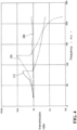
- Fig. 4 is the explanation view showing the attenuation characteristics.
- a longitudinal axis indicates a transmission rate of the vibration.
- a lateral axis indicates a frequency (Hz) of the vibration.
- a region in which the transmission rate is 1.0 or less is an attenuation region, and an attenuation effect of the vibration is obtained.
- point of the maximum value of the conduction rate indicates a resonance point. when the frequency (Hz) at this resonance point is low, the attenuation efficiency (namely, the buffering effect) is good. That is, at a time point when the frequency (Hz) of the vibration is low, the attenuation of the vibration is started, thereby resulting in the good attenuation efficiency (namely, good buffering effect).
- the attenuation characteristic (III) of the fastener described in the Patent No. 6038145 Gazette as indicated by a one-point chain line curve, even at a time point when the frequency (Hz) is about 220 (Hz), the attenuation efficiency is not obtained in this example. Also, with regard to the attenuation characteristic (II) of the fastener in the above patent document 1, as indicated by a dashed line curve, at a time point when the frequency (Hz) is high (large), in this example, at a time point of about 125 (Hz), the attenuation efficiency is obtained because it comes in the attenuation region.
- the attenuation property (I) of the fastener 3 and shield unit 1 according to this embodiment as indicated by a solid line curve, at a time point when the frequency (Hz) is low (small), in this example, at a time point of about 85 (Hz), the attenuation efficiency is obtained because it comes in the attenuation region.
- the attenuation characteristic (I) of the fastener 3 and shield unit 1 according to this embodiment is compared with the attenuation characteristic (II) of the fastener in the above patent document 1, the frequency (Hz) at the resonance point is 40 (Hz) lower (smaller) in this example.
- the sufficient buffering effect can be obtained by its difference.
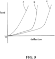
- a curve A indicates a load-deflection characteristic of the first spring 7 configured by the wire mesh.
- a curve B indicates a load-deflection characteristic of the second spring 8 configured by the wave washer.
- the load-deflection characteristic of the spring part in the fastener 3 and shield unit 1 is the synthesis (series connection) of the load-deflection characteristic (curve A) of the first spring 7 configured by the wire mesh and the load-deflection characteristic (curve B) of the second spring 8 that is the wave washer, as indicated by a curve C.
- the transmission to the shield member 2 of the vibration of the structure 4 can be suppressed, thereby obtaining the adequate shock absorption effect.
- the first spring 7 in the spring part is composed of: the sleeve-shaped spring 70 in which the flange 72 is integrally provided at one end; and the ring-shaped spring 71 fitted to the other end of the sleeve-shaped spring 70, and the flange 72 of the sleeve-shaped spring 70 and the ring-shaped spring 71 are each interposed between the two flange parts (namely, the flange part 62 of the sleeve 6 and the ring 60) and the both sides (upper and lower sides) of the shield member 2.
- the fastener 3 and shield unit 1 As a result, in the fastener 3 and shield unit 1 according to this embodiment, the flange part 72 of the sleeve-shaped spring 70 in the first spring 7 and the ring-shaped spring 71, together with the second spring 8 composed of the upper and lower two wave washers which are each interposed between the two flange parts and the both sides of the shield member 2, suppress the vibration of the structure 4 from being transmitted to the shield member 2. Accordingly, in the fastener 3 and shield unit 1 according to this embodiment, it is possible to obtain the sufficient buffering effect.
- the cylindrical part of the sleeve-shaped spring 70 in the first spring 7 in the spring part is interposed between the fixing boss part 40 of the structure 4 and the head part of the bolt 50 as the fixing component, through the flange part 62 of the sleeve 6 and the ring 60.
- the cylindrical part of the sleeve-shaped spring 70 surely suppresses the vibration of the structure 4 from being transmitted to the shield member 2, due to the flange 72 of the sleeve-shaped spring 70, the ring-shaped spring 71 and the second springs 8.
- the cylindrical part of the sleeve-shaped spring 70 is interposed between the outer surface of the cylindrical part 61 in the sleeve 6 and the inner surface of the hole 20 of the shield member 2.
- the cylindrical part of the sleeve-shaped spring 70 can prevents the outer surface of the cylindrical part 61 of the sleeve 6 and the inner surface of the hole 20 in the shield member 2 from hitting each other. Consequently, it is possible to improve the durability and avoid the generation of sound.
- the upper and lower two washers 9 as the interposing parts are each interposed between the both sides (upper and lower sides) of the shield member 2 and the second spring 8 composed of the upper and lower two wave washers in the spring parts.
- a spring force of the second spring 8 and a spring force of the first spring 7 act in surface contact state on the shield member 2 through the washers 9. Consequently, in the fastener 3 and shield unit 1 according to this embodiment, it is possible to surely suppress the vibration of the structure 4 from being transmitted to the shield member 2. Thus, it is possible to obtain the more sufficient buffering effect.
- the upper and lower two washers 9 as the interposing parts can prevents the both sides (upper and lower sides) of the shield member 2 and the second spring 8 of the upper and lower two wave washers in the spring parts from hitting each other. Consequently, it is possible to improve the durability and avoid the generation of sound.
- outer circumferential edge portions of the upper and lower two washers (dish washers) 9 as the interposing parts are curved, so the curved surfaces of those washers 9 hit the both sides (upper and lower sides) of the shield member 2. That is, the corners of the outer circumferential edge portions of the curved part 9 do not bite into the both sides (upper and lower sides) of the shield member 2. Thus, the durability can be improved.
- the first spring 7 in the spring part is the spring configured by the wire mesh
- the second spring 8 in the spring part is the wave washer.
- the first spring 7 in the spring part is the spring configured by the wire mesh.
- the sleeve-shaped spring 70 in which the flange 72 is integrally provided at one end is suitable for fitting the ring-shaped spring 71 to the other end of the sleeve-shaped spring 70.
- the fastener 3 and shield unit 1 according to this embodiment it is possible to easily manufacture the sleeve-shaped spring 70 in which the flange 72 is integrally provided at one end, and the ring-shaped spring 71.
- the cylindrical part and the two flange parts are composed of two parts: a sleeve integrally composed of the cylindrical part 61 and the flange part, and the ring 60 as the flange part.
- the cylindrical part and the two flange parts are composed of three parts: the cylindrical part 61 and the flange part 62, which are divided from the sleeve 6 of which the cylindrical part 61 and the flange part 62 are integral structures, and the ring 60 as the flange part.
- the second springs 8 consisting of the two wave washers are each interposed between the two flange parts, namely, the flange part 62 of the sleeve 6 and the ring 60 as the flange part, and both sides (upper and lower sides) of the shield member 2.
- the second spring 8 of one wave washer is interposed between one flange part, namely, the flange part 62 of the sleeve 6 or the ring 60 as the flange part, and one surface (upper surface or lower surface) of the shield member 2.
- the first spring 7 of the spring part composed of the cylindrical sleeve-shaped spring 70 in which the flange part 72 is integrally provided at one end (lower end), and the ring-shaped spring 71.
- the first spring of the spring part may consist of two flange-shaped or ring-shaped springs, or composed of two flange-shaped or ring-shaped springs and one cylindrical spring.
- the washer 9 is used as the interposing part.
- a member other than the washer 9, such as a gasket or the other member may be used as the interposing part.
- the spring configured by the wire mesh (the sleeve-shaped spring 70 and the ring-shaped spring 71) is used as the first spring 7.
- a spring other than the spring configured by the wire mesh may be used as the first spring.
- the wave washer is used as the second spring 8.
- a spring other than the wave washer may be used as the second spring.
- the fastener in the present invention is not limited by the above-mentioned embodiments.
Landscapes
- Engineering & Computer Science (AREA)
- General Engineering & Computer Science (AREA)
- Mechanical Engineering (AREA)
- Chemical & Material Sciences (AREA)
- Combustion & Propulsion (AREA)
- Transportation (AREA)
- Bolts, Nuts, And Washers (AREA)
- Cooling, Air Intake And Gas Exhaust, And Fuel Tank Arrangements In Propulsion Units (AREA)
- Exhaust Silencers (AREA)
- Connection Of Plates (AREA)
- Vibration Prevention Devices (AREA)
Abstract
Description
- The present invention relates to a fastener to fasten a shield member to a structure. Also, the present invention relates to a shield unit that includes the shield member and the fastener.
- As a fastener to fasten a shield member to a structure, for example, there is a
patent document 1 as described below. The fastener in thepatent document 1 includes a support component to fasten a shield member such as a heat insulator or the like to a structure such as an exhaust manifold or the like, and bolts. - The support component has a cylindrical body penetrating through a hole made in the heat insulator, a washer fitted to one end of the tube body, a flange formed in the other one end of the cylindrical body, and elastic bodies which are secured between the washer and the heat insulator and between the lange and the heat insulator, respectively.
- The bolt is screwed into fastening target sections of the exhaust manifold, through the cylindrical body of the support. Accordingly, the heat insulator is fastened to the exhaust manifold.
- [Patent Document 1] Patent No.
5885258 Gazette - In the foregoing fastener, it is important to obtain asufficient buffering effect by suppressing the transmission of vibrations of structures such as the exhaust manifold to the shield member such as the heat insulator.
- The problem to be solved by the present invention is to provide a fastener from which the sufficient buffering effect can be obtained and a shield unit.
- A fastener in the present invention is a fastener for fastening a shield member to a structure, and comprises: a support part for supporting the shield member, and a fixing component for fixing the shield member through the support component to the structure, wherein the support part has: a cylindrical part which is inserted into a hole provided in the shield member and into which the fixing component is inserted; two flange parts which are each provided at both ends of the cylindrical part and opposite to each other on both sides of the shield member; and spring parts which are interposed between each of the two flange parts and both sides of the shield member, and wherein the spring parts have a first spring and a second spring with different load -deflection characteristic, the first spring is interposed between each of the two flange parts and the both sides of the shield member, and the second spring is interposed between at least one of the two flange parts and at least one of the both sides of the shield member.
- In the fastener according to this invention,it is preferable that the cylindrical part and the two flange parts are configured by: a sleeve in which a flange part is integrally provided at one end, and a ring fitted to the other end of the sleeve, the first spring is composed of: a sleeve-shaped spring in which a flange is integrally provided at one end and a ring-shaped spring fitted to the other end of the sleeve-shaped spring, the sleeve-shaped spring is inserted into the hole of the shield member and fitted to the sleeve from outside, the flange of the sleeve-shaped spring is interposed between one of the two flange parts and one of the both sides of the shield member, and the ring-shaped spring is interposed between the other of the two flange parts and the other of the both sides of the shield member.
- In the fastener according to this invention, it is preferable that the support component has interposing parts which are each interposed between the both sides of the shield member and the spring part.
- In the fastener according to this invention, it is preferable that the first spring is a spring configured by wire mesh, and the second spring is a wave washer.
- A shield unit according to this inventioncomprises: a shield member for shielding a structure from transmitting its influence to surroundings; and the fastener in the present invention, wherein the shielding member has a hole into which the cylindrical part of the fastener is inserted.
- The fastener and the shielding unit according to the present invention provide a sufficient buffering effect.
-
-
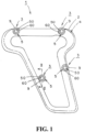
Fig. 1 is a usage situation view showing an embodiment of a fastener and a shield unit according to the present invention, -
Fig. 2 is a longitudinal cross-sectional view (a II-II line cross-sectional view inFig. 1 ) showing a main portion, -
Fig. 3 is an exploded side view showing a main portion (a side view corresponding toFig. 2 ), -
Fig. 4 is an explanatory view showing an attenuation characteristic, and -
Fig. 5 is an explanatory view showing a load -deflection characteristic of a spring part. - Hereafter, one example of the embodiment (implementation) of the fastener and shield unit according to the present invention will be described in detail with reference to the drawings. By the way, since the drawings are the schematic views, the main components are shown, and the illustrations of components other than the main components are omitted. Also, a part of hatching is omitted, or a part of a cross-section is omitted.
- Hereafter, configurations of a
fastener 3 and ashield unit 1 according to this embodiment will be explained. - As shown in
Fig. 1 to Fig. 3 , theshield unit 1 according to this embodiment includes a shield member (an insulator, a heat insulator or the like) 2, and thefastener 3 according to this embodiment. - In this example, the
shield member 2 is a metal member and configured by a metal cover member, a metal plate member and others. Theshield member 2 shields an influence of a structure 4 from being transmitted to surroundings. That is, theshield member 2 protects the components, devices, members and others around the structure 4 from the influence of the structure 4. - The structure 4 is, for example, an exhaust manifold, an outlet pipe of a turbine and the like. As the influence of the structure 4, for example, there are heat, sound and others generated in the structure 4. In the structure 4, a
fixing boss part 40 as a fixing part is integrally provided at a location to which theshield member 2 is fixed. Ascrew hole 41 is provided at thefixing boss part 40. - In the
shield member 2, ahole 20 is provided at a location corresponding to thefixing boss part 40. In this example, thehole 20 is circular in shape. Acylindrical part 61 of asleeve 6 in thefastener 3 is inserted into thishole 20. - The
holes 20 of theshielding member 2 and thefixing boss part 40 of the structure 4 are provided four each in this example. By the way, the number and locations of theholes 20 and thefixing boss parts 40 are not limited to this example. - The
fastener 3 includes asupport component 5, and abolt 50 as a fixing component. Thesupport component 5 supports theshield member 2. Thebolt 50 fix theshield member 2 to the structure 4 via the support component. - As shown in
Fig. 2 andFig. 3 , thesupport component 5 has thesleeve 6 and aring 60, afirst spring 7 and asecond spring 8 which serve as spring parts, and two washers (dish washers) 9 as interposing parts. - The
sleeve 6 has thecylindrical part 61 and aflange part 62. An inner diameter of thecylindrical part 61 is approximately equal to an inner diameter of thescrew hole 41 in thefixing boss part 40. Thecylindrical part 61 is inserted into thehole 20 in theshield member 2. Thebolt 50 is inserted into thecylindrical part 61. - The
flange part 62 is integrally provided at one end (lower end) of thecylindrical part 61. Anengagement groove 63 is provided in a circumferential direction on an outer circumference surface of the other end (upper end) of thecylindrical part 61. On the other hand, an engagingconvex part 64 engaged in theengagement groove 63 is provided in the circumferential direction on an inner circumference surface of thering 60 as a flange part. - The
first spring 7 as the spring part is the spring configured by wire mesh, in this example. Also, thesecond spring 8 as the spring part is the spring configured by two wave washers, in this example. - As a result, as indicated in a load-deflection (displacement) characteristic of a spring in
Fig. 5 , a load -deflection characteristic of the first spring 7 (a curve A inFig. 5 ) and a load-deflection characteristic of the second spring 8 (a curve B inFig. 5 ) differ from each other. - The
first spring 7 is composed of a sleeve-shapedspring 70 and a ring-shapedspring 71. The sleeve-shapedspring 70 is cylindrical in shape, and aflange 72 is integrally provided at one end (lower end). An inner diameter of the sleeve-shapedspring 70 that is cylindrical in shape is approximately equal to or slightly larger than an outer diameter of thecylindrical part 61 of thesleeve 6. - An inner diameter of the ring-shaped
spring 71 is approximately equal to or slightly smaller than an outer diameter of the other end (upper end) of the sleeve-shapedspring 70. The ring-shapedspring 71 is fitted to the other end of the sleeve-shapedspring 70. - At first, as shown in
Fig. 2 andFig. 3 , in theshield member 2, the twowashers 9 are each applied to both sides (upper and lower sides) of the location at which thehole 20 is provided and arranged there. - Next, the
second springs 8 of two wave washers is placed in contact with twowashers 9, the upper and lower, respectively. - In succession, the sleeve-shaped
spring 70 of thefirst spring 7 is inserted from below into through holes of the twosecond springs 8, through holes of the twowashers 9 and thehole 20 of theshield member 2. Theflange 72 of this sleeve-shapedspring 70 is placed in contact with thesecond spring 8 of the lower wave washer. Also, the ring-shapedspring 71 of thefirst spring 7 is fitted from outside to the other end (upper end) of this sleeve-shapedspring 70. This ring-shapedspring 71 is placed in contact with thesecond spring 8 of the upper wave washer. - Then, the
cylindrical part 61 of thesleeve 6 is inserted from below into the sleeve-shapedspring 70. Theflange part 62 of thissleeve 6 is placed against theflange 72 of the sleeve-shapedspring 70 from below. Also, the engagingconvex part 64 of thering 60 is fitted from outside to theengagement groove 63 of thissleeve 6. Accordingly, thesupport component 5 of thefastener 3 is assembled to theshield member 2. - At this time, the cylindrical part, namely, the
cylindrical part 61 of thesleeve 6 is inserted into thehole 20 of theshield member 2. The two flange parts, namely, theflange part 62 of thesleeve 6 and thering 60 as the flange part are opposite to each other on both sides (upper and lower sides) of theshield member 2. - Also, the spring parts, namely, the
first springs 7 and thesecond springs 8 are each interposed between the two flange parts, namely, theflange part 62 of thesleeve 6 and thering 60 as the flange part, and the both sides (upper and lower sides) of theshield member 2, through the upper and lower twowashers 9. - Moreover, the sleeve-shaped
spring 70 of thefirst spring 7 is fitted from outside to thesleeve 6, namely, thecylindrical part 61 of thesleeve 6. - Furthermore, the
flange 72 of the sleeve-shapedspring 70 in thefirst spring 7 is interposed between one of the two flange parts, namely, theflange part 62 of thesleeve 6 and one of the both sides of theshield member 2, namely, the lower side, through thelower washer 9. - Furthermore, the ring-shaped
spring 71 of thefirst spring 7 is interposed between the other one of the two flange parts, namely, thering 60 as the flange part, and the other side of the both sides of theshield member 2, namely, the upper side, through theupper washer 9. - Furthermore, the upper and lower two
washers 9 as the interposing parts are interposed between the both sides (upper and lower sides) of theshield member 2, and thesecond spring 8 of the upper and lower two wave washers. - And, as shown in
Fig. 1 andFig. 2 , the structure 4 is covered by theshield member 2. Also, thesupport component 5 in thefastener 3 assembled to theshield member 2 is positioned at the fixingboss part 40 of the structure 4. Moreover, a hollow part of thecylindrical part 61 in thesupport component 5 is positionally matched with thescrew hole 41 of the fixingboss part 40. And, the screw part of thebolt 50 in thefastener 3 is inserted into thecylindrical part 61 and screwed into thescrew hole 41 of the fixingboss part 40. - As a result, the
support component 5 is sandwiched and secured between a head part of thebolt 50 and the fixingboss part 40. Consequently, theshield member 2 is fastened to the structure 4, through thesupport component 5 andbolt 50 in thefastener 3. - The
fastener 3 andshield unit 1 according to this embodiment are structured by the foregoing configuration. Their actions will be explained below. - The
shield member 2 is fastened to the structure 4 by thefastener 3 in a situation in which the structure 4 is covered. Accordingly, theshield member 2 shields the heat, sound and others generated in the structure 4. As a result, theshield member 2 protects the components, devices, members and others around the structure 4 from being inflected by the heat, sound and others generated in the structure 4. - The
fastener 3 supports theshield member 2 by means of thesupport component 5 and fastens the shieldingmember 2 to the fixingboss part 40 of the structure 4 by means of thebolt 50 as the fixing component. As a result, in thefastener 3, vibration generated in the structure 4 is absorbed and buffered by thesupport component 5, and the vibration generated in the structure 4 is prevented from being transmitted to theshield member 2. - The
fastener 3 andshield unit 1 according to this embodiment have the above configuration and actions. Their effect will be explained below. - With regard to the
fastener 3 andshield unit 1 according to this embodiment, thefirst spring 7 and thesecond spring 8 in which their load - deflection characteristics differ from each other are interposed between theshield member 2 and the structure 4. Thus, the vibrations of the structure 4 are suppressed from being transmitted to theshield member 2, providing sufficient buffering effect. - Due to the foregoing, the
fastener 3 andshield unit 1 according to this embodiment suppresed a transmission of vibration of the structure 4 to theshield member 2 by the sufficient buffering effect. As a result, it is possible to surely prevent damage such as crack and the like from occurring in theshield member 2 due to vibration of the structure 4. - Moreover, in the
fastener 3 andshield unit 1 according to this embodiment, gap is not provided between theshield member 2 and thefirst spring 7 andsecond spring 8, for the purpose of cutting off the transmission (input) of the vibration of the structure 4 to theshield member 2. Thus, sound swing (noise) is never deteriorated. - Hereafter, with reference to
Fig. 4 , an attenuation characteristic (I) of thefastener 3 andshield unit 1 according to this embodiment is compared with an attenuation characteristic (II) of a fastener in theabove patent document 1 that is a fastener according to a comparison example and an attenuation characteristic (III) of a fastener described in Patent No.6038145 Gazette - The fastener in the
above patent document 1 is the fastener in which springs (elastic bodies, for example, wire meshes) are interposed between a washer, a flange part and a heat insulator, respectively. The fastener described in the Patent No.6038145 Gazette -
Fig. 4 is the explanation view showing the attenuation characteristics. A longitudinal axis indicates a transmission rate of the vibration. A lateral axis indicates a frequency (Hz) of the vibration. A region in which the transmission rate is 1.0 or less is an attenuation region, and an attenuation effect of the vibration is obtained. Also, as indicated in the attenuation characteristics (I) and (II), point of the maximum value of the conduction rate indicates a resonance point. when the frequency (Hz) at this resonance point is low, the attenuation efficiency (namely, the buffering effect) is good. That is, at a time point when the frequency (Hz) of the vibration is low, the attenuation of the vibration is started, thereby resulting in the good attenuation efficiency (namely, good buffering effect). - With regard to the attenuation characteristic (III) of the fastener described in the Patent No.
6038145 Gazette above patent document 1, as indicated by a dashed line curve, at a time point when the frequency (Hz) is high (large), in this example, at a time point of about 125 (Hz), the attenuation efficiency is obtained because it comes in the attenuation region. - On the other hand, with regard to the attenuation property (I) of the
fastener 3 andshield unit 1 according to this embodiment, as indicated by a solid line curve, at a time point when the frequency (Hz) is low (small), in this example, at a time point of about 85 (Hz), the attenuation efficiency is obtained because it comes in the attenuation region. Moreover, when the attenuation characteristic (I) of thefastener 3 andshield unit 1 according to this embodiment is compared with the attenuation characteristic (II) of the fastener in theabove patent document 1, the frequency (Hz) at the resonance point is 40 (Hz) lower (smaller) in this example. Thus, the sufficient buffering effect can be obtained by its difference. - Here, the load-deflection characteristic of the spring part is explained with reference to
Fig. 5 . A curve A indicates a load-deflection characteristic of thefirst spring 7 configured by the wire mesh. Also, a curve B indicates a load-deflection characteristic of thesecond spring 8 configured by the wave washer. - The load-deflection characteristic of the spring part in the
fastener 3 andshield unit 1 according to this embodiment is the synthesis (series connection) of the load-deflection characteristic (curve A) of thefirst spring 7 configured by the wire mesh and the load-deflection characteristic (curve B) of thesecond spring 8 that is the wave washer, as indicated by a curve C. - As a result, in the
fastener 3 andshield unit 1 according to this embodiment, as mentioned above, the transmission to theshield member 2 of the vibration of the structure 4 can be suppressed, thereby obtaining the adequate shock absorption effect. - In the
fastener 3 andshield unit 1 according to this embodiment, thefirst spring 7 in the spring part is composed of: the sleeve-shapedspring 70 in which theflange 72 is integrally provided at one end; and the ring-shapedspring 71 fitted to the other end of the sleeve-shapedspring 70, and theflange 72 of the sleeve-shapedspring 70 and the ring-shapedspring 71 are each interposed between the two flange parts (namely, theflange part 62 of thesleeve 6 and the ring 60) and the both sides (upper and lower sides) of theshield member 2. As a result, in thefastener 3 andshield unit 1 according to this embodiment, theflange part 72 of the sleeve-shapedspring 70 in thefirst spring 7 and the ring-shapedspring 71, together with thesecond spring 8 composed of the upper and lower two wave washers which are each interposed between the two flange parts and the both sides of theshield member 2, suppress the vibration of the structure 4 from being transmitted to theshield member 2. Accordingly, in thefastener 3 andshield unit 1 according to this embodiment, it is possible to obtain the sufficient buffering effect. - Moreover, in the
fastener 3 andshield unit 1 according to this embodiment, the cylindrical part of the sleeve-shapedspring 70 in thefirst spring 7 in the spring part is interposed between the fixingboss part 40 of the structure 4 and the head part of thebolt 50 as the fixing component, through theflange part 62 of thesleeve 6 and thering 60. As a result, in thefastener 3 andshield unit 1 according to this embodiment, the cylindrical part of the sleeve-shapedspring 70 surely suppresses the vibration of the structure 4 from being transmitted to theshield member 2, due to theflange 72 of the sleeve-shapedspring 70, the ring-shapedspring 71 and the second springs 8. Thus, it is possible to obtain the more sufficient buffering effect. - Moreover, in the
fastener 3 andshield unit 1 according to this embodiment, the cylindrical part of the sleeve-shapedspring 70 is interposed between the outer surface of thecylindrical part 61 in thesleeve 6 and the inner surface of thehole 20 of theshield member 2. Thus, even if theshield member 2 and the structure 4 are shifted laterally (in a direction parallel to the surface of the shield member 2), the cylindrical part of the sleeve-shapedspring 70 can prevents the outer surface of thecylindrical part 61 of thesleeve 6 and the inner surface of thehole 20 in theshield member 2 from hitting each other. Consequently, it is possible to improve the durability and avoid the generation of sound. - In the
fastener 3 andshield unit 1 according to this embodiment, the upper and lower twowashers 9 as the interposing parts are each interposed between the both sides (upper and lower sides) of theshield member 2 and thesecond spring 8 composed of the upper and lower two wave washers in the spring parts. As a result, in thefastener 3 andshield unit 1 according to this embodiment, a spring force of thesecond spring 8 and a spring force of thefirst spring 7 act in surface contact state on theshield member 2 through thewashers 9. Consequently, in thefastener 3 andshield unit 1 according to this embodiment, it is possible to surely suppress the vibration of the structure 4 from being transmitted to theshield member 2. Thus, it is possible to obtain the more sufficient buffering effect. - Moreover, in the
fastener 3 andshield unit 1 according to this embodiment, the upper and lower twowashers 9 as the interposing parts can prevents the both sides (upper and lower sides) of theshield member 2 and thesecond spring 8 of the upper and lower two wave washers in the spring parts from hitting each other. Consequently, it is possible to improve the durability and avoid the generation of sound. - Moreover, in the
fastener 3 andshield unit 1 according to this embodiment, outer circumferential edge portions of the upper and lower two washers (dish washers) 9 as the interposing parts are curved, so the curved surfaces of thosewashers 9 hit the both sides (upper and lower sides) of theshield member 2. That is, the corners of the outer circumferential edge portions of thecurved part 9 do not bite into the both sides (upper and lower sides) of theshield member 2. Thus, the durability can be improved. - In the
fastener 3 andshield unit 1 according to this embodiment, thefirst spring 7 in the spring part is the spring configured by the wire mesh, and thesecond spring 8 in the spring part is the wave washer. As a result, in thefastener 3 andshield unit 1 according to this embodiment, the load-deflection characteristic of thefirst spring 7 differs from the load-deflection characteristic of thesecond spring 8, and the vibration of the structure 4 is surely suppressed from being transmitted to theshield member 2. Thus, it is possible to obtain the more sufficient buffering effect. - In the
fastener 3 andshield unit 1 according to this embodiment, thefirst spring 7 in the spring part is the spring configured by the wire mesh. Thus, it is suitable for manufacturing the sleeve-shapedspring 70 in which theflange 72 is integrally provided at one end. Moreover, it is suitable for fitting the ring-shapedspring 71 to the other end of the sleeve-shapedspring 70. As a result, in thefastener 3 andshield unit 1 according to this embodiment, it is possible to easily manufacture the sleeve-shapedspring 70 in which theflange 72 is integrally provided at one end, and the ring-shapedspring 71. Moreover, it is possible to easily assemble. - In this embodiment, an example is explained that the cylindrical part and the two flange parts are composed of two parts: a sleeve integrally composed of the
cylindrical part 61 and the flange part, and thering 60 as the flange part. However, in this invention, it can also be applied to the case in which the cylindrical part and the two flange parts are composed of three parts: thecylindrical part 61 and theflange part 62, which are divided from thesleeve 6 of which thecylindrical part 61 and theflange part 62 are integral structures, and thering 60 as the flange part. - In this embodiment, an example will be described the
second springs 8 consisting of the two wave washers are each interposed between the two flange parts, namely, theflange part 62 of thesleeve 6 and thering 60 as the flange part, and both sides (upper and lower sides) of theshield member 2. However, in the present invention, thesecond spring 8 of one wave washer is interposed between one flange part, namely, theflange part 62 of thesleeve 6 or thering 60 as the flange part, and one surface (upper surface or lower surface) of theshield member 2. - In this embodiment, an example will be described the
first spring 7 of the spring part composed of the cylindrical sleeve-shapedspring 70 in which theflange part 72 is integrally provided at one end (lower end), and the ring-shapedspring 71. However, in the present invention, the first spring of the spring part may consist of two flange-shaped or ring-shaped springs, or composed of two flange-shaped or ring-shaped springs and one cylindrical spring. - In this embodiment, an example will be described the
washer 9 is used as the interposing part. However, in the present invention, a member other than thewasher 9, such as a gasket or the other member may be used as the interposing part. - In this embodiment, the spring configured by the wire mesh (the sleeve-shaped
spring 70 and the ring-shaped spring 71) is used as thefirst spring 7. However, in the present invention,a spring other than the spring configured by the wire mesh may be used as the first spring. - In this embodiment, the wave washer is used as the
second spring 8. However, in the present invention, a spring other than the wave washer may be used as the second spring. - By the way, the fastener in the present invention is not limited by the above-mentioned embodiments.
-
- 1
- shield unit
- 2
- shield member
- 20
- hole
- 3
- fastener
- 4
- structure
- 40
- fixing boss part
- 41
- screw hole
- 5
- support component
- 50
- bolt (fixing component)
- 6
- sleeve
- 60
- ring
- 61
- cylindrical part
- 62
- flange part
- 63
- engagement groove
- 64
- engaging convex part
- 7
- first spring (spring part)
- 70
- sleeve-shaped spring
- 71
- ring-shaped spring
- 72
- flange
- 8
- second spring (spring part)
- 9
- washer (interposing part)
- A
- curve indicating load-deflection characteristic of first spring
- B
- curve indicating load-deflection characteristic of second spring
- C
- curve indicating load-deflection characteristic of combination of first spring and second spring
- (I)
- curve indicating attenuation characteristic of the
fastener 3 - (II)
- according to this embodiment curve indicating attenuation characteristic of a fastener (the fastener in above patent document 1) according to comparison example in which spring is used
- (III)
- curve indicating attenuation property of fastener (fastener described in Patent No.
6038145 Gazette
Claims (5)
- A fastener for fastening a shield member to a structure, comprising:a support component for supporting the shield member; anda fixing component for fixing the shield member through the support component to the structure,wherein the support component has:a cylindrical part which is inserted into a hole provided in the shield member and into which the fixing component is inserted;two flange parts which are each provided at both ends of the cylindrical part and opposite to each of both sides of the shield member; andspring parts which are interposed between each of the two flange parts and both sides of the shield member, andwherein the spring parts have a first spring and a second spring with different load-deflection characteristic,the first spring is interposed between each of the two flange parts and the both sides of the shield member, andthe second spring is interposed between at least one of the two flange parts and at least one of the both sides of the shield member.
- The fastener according to the claim 1,wherein the cylindrical part and the two flange parts are configured by a sleeve in which a flange part is integrally provided at one end and a ring fitted to the other end of the sleeve,the first spring is composed of a sleeve-shaped spring in which a flange is integrally provided at one end and a ring-shaped spring fitted to the other end of the sleeve-shaped spring,the sleeve-shaped spring is inserted into thehole of the shield member and fitted to the sleeve from outside,the flange of the sleeve-shaped spring is interposed between one of the two flange parts and one of the both sides of the shield member, andthe ring-shaped spring is interposed between the other of the two flange parts and the other of the both sides of said shield member.
- The fastener according to the claim 1 or 2, wherein the support component has interposing parts which are each interposed between the both sides of the shield member and the spring parts.
- The fastener described according to any one of the claims 1 to 3,
wherein the first spring is a spring configured by wire mesh, and the second spring is a wave washer. - A shield unit comprising:a shield member for shielding a structure from transmitting its influence to surroundings; andthe fastener according to any one of the claims 1 to 4,wherein the shielding member has a hole into which the cylindrical part of the fastener is inserted.
Applications Claiming Priority (2)
| Application Number | Priority Date | Filing Date | Title |
|---|---|---|---|
| JP2020057772A JP7411472B2 (en) | 2020-03-27 | 2020-03-27 | Fasteners, shielding units |
| PCT/JP2021/002630 WO2021192580A1 (en) | 2020-03-27 | 2021-01-26 | Fastener and shield unit |
Publications (2)
| Publication Number | Publication Date |
|---|---|
| EP4129731A1 true EP4129731A1 (en) | 2023-02-08 |
| EP4129731A4 EP4129731A4 (en) | 2024-04-24 |
Family
ID=77891236
Family Applications (1)
| Application Number | Title | Priority Date | Filing Date |
|---|---|---|---|
| EP21775167.6A Pending EP4129731A4 (en) | 2020-03-27 | 2021-01-26 | Fastener and shield unit |
Country Status (5)
| Country | Link |
|---|---|
| US (1) | US20230057516A1 (en) |
| EP (1) | EP4129731A4 (en) |
| JP (1) | JP7411472B2 (en) |
| CN (1) | CN115280024A (en) |
| WO (1) | WO2021192580A1 (en) |
Families Citing this family (1)
| Publication number | Priority date | Publication date | Assignee | Title |
|---|---|---|---|---|
| US11976684B2 (en) * | 2020-01-22 | 2024-05-07 | Illinois Tool Works Inc. | Floating connector and connector assembly |
Family Cites Families (10)
| Publication number | Priority date | Publication date | Assignee | Title |
|---|---|---|---|---|
| JPS5442055B2 (en) * | 1973-12-06 | 1979-12-12 | ||
| JP2005030571A (en) * | 2003-07-11 | 2005-02-03 | Nichias Corp | Shock absorbing washer member and vibration-proof heat shielding plate equipped therewith |
| DE102005024864A1 (en) * | 2005-05-31 | 2006-12-28 | Reinz-Dichtungs-Gmbh | heat shield |
| JP2007255693A (en) * | 2006-03-25 | 2007-10-04 | Isamu Yamazaki | Bolt tightening force detection seat with detachable and attachable ring |
| JP5255426B2 (en) * | 2008-12-26 | 2013-08-07 | 三和パッキング工業株式会社 | Mount member |
| JP5566848B2 (en) * | 2010-03-03 | 2014-08-06 | 株式会社神戸製鋼所 | Sound insulation structure and sound insulation cover |
| US9133869B2 (en) | 2011-08-01 | 2015-09-15 | Elringklinger Ag | Shielding device with a shielding element and at least one temperature and oscillation-decoupled fastening device |
| JP5885258B2 (en) * | 2013-05-21 | 2016-03-15 | トヨタ自動車株式会社 | Fastening structure of heat insulator |
| DE102015118117A1 (en) * | 2015-10-23 | 2017-04-27 | Elringklinger Ag | Plate-like component with a plate-like component by cross-fastening device |
| JP2019072815A (en) * | 2017-10-17 | 2019-05-16 | 株式会社マキタ | Driving tool |
-
2020
- 2020-03-27 JP JP2020057772A patent/JP7411472B2/en active Active
-
2021
- 2021-01-26 WO PCT/JP2021/002630 patent/WO2021192580A1/en active Application Filing
- 2021-01-26 EP EP21775167.6A patent/EP4129731A4/en active Pending
- 2021-01-26 CN CN202180020470.2A patent/CN115280024A/en active Pending
- 2021-01-26 US US17/914,861 patent/US20230057516A1/en active Pending
Also Published As
| Publication number | Publication date |
|---|---|
| JP2021156373A (en) | 2021-10-07 |
| US20230057516A1 (en) | 2023-02-23 |
| EP4129731A4 (en) | 2024-04-24 |
| JP7411472B2 (en) | 2024-01-11 |
| WO2021192580A1 (en) | 2021-09-30 |
| CN115280024A (en) | 2022-11-01 |
Similar Documents
| Publication | Publication Date | Title |
|---|---|---|
| WO2017061588A1 (en) | Coupling | |
| EP4129731A1 (en) | Fastener and shield unit | |
| JP5002300B2 (en) | Soundproof cover and its mounting structure | |
| JP2008248809A5 (en) | ||
| JP5590752B2 (en) | Sound insulation structure and sound insulation cover | |
| JP2004507668A (en) | Tightening device for filter muffler at compressor inlet of turbocharger | |
| US20080236693A1 (en) | Exhaust pipe assembly | |
| JP5922620B2 (en) | Anti-vibration mounting structure for heat shield cover to exhaust system parts | |
| JPH11294535A (en) | Vibration control bushing and joint device | |
| CN215488333U (en) | Pipeline vibration absorber | |
| JP2004169733A (en) | Vibration isolation structure | |
| JP2007113479A (en) | Heat shield plate | |
| JPH0333895B2 (en) | ||
| US5956950A (en) | Arrangement for isolating torsional vibration | |
| JPH08326811A (en) | Vibration control device | |
| JP2002174289A (en) | Vibration damping bolt and fastening structure with vibration damping function imparted thereto | |
| CN211820553U (en) | Sound insulation cover vibration damper and engine with same | |
| JP2016121639A (en) | Cover member | |
| JP2007137298A (en) | Elastic vibration reduction structure of muffler | |
| JP2000291711A (en) | Buffer washer and buffering structure | |
| US20030136217A1 (en) | Anti-noise starter flywheel | |
| JP2000320306A (en) | Thin-wall structure attaching structure for reducing in vibration control and reduction of thermal stress | |
| JP2019148303A (en) | Dynamic damper | |
| JP2001115853A (en) | Supporting device for heat shielding plate | |
| JP2019167934A (en) | Aftertreatment device |
Legal Events
| Date | Code | Title | Description |
|---|---|---|---|
| STAA | Information on the status of an ep patent application or granted ep patent |
Free format text: STATUS: THE INTERNATIONAL PUBLICATION HAS BEEN MADE |
|
| PUAI | Public reference made under article 153(3) epc to a published international application that has entered the european phase |
Free format text: ORIGINAL CODE: 0009012 |
|
| STAA | Information on the status of an ep patent application or granted ep patent |
Free format text: STATUS: REQUEST FOR EXAMINATION WAS MADE |
|
| 17P | Request for examination filed |
Effective date: 20220923 |
|
| AK | Designated contracting states |
Kind code of ref document: A1 Designated state(s): AL AT BE BG CH CY CZ DE DK EE ES FI FR GB GR HR HU IE IS IT LI LT LU LV MC MK MT NL NO PL PT RO RS SE SI SK SM TR |
|
| DAV | Request for validation of the european patent (deleted) | ||
| DAX | Request for extension of the european patent (deleted) | ||
| A4 | Supplementary search report drawn up and despatched |
Effective date: 20240326 |
|
| RIC1 | Information provided on ipc code assigned before grant |
Ipc: F01N 13/14 20100101ALI20240320BHEP Ipc: F01N 13/08 20100101ALI20240320BHEP Ipc: F16B 5/02 20060101ALI20240320BHEP Ipc: F16B 39/24 20060101ALI20240320BHEP Ipc: F16B 43/00 20060101ALI20240320BHEP Ipc: B60K 13/04 20060101AFI20240320BHEP |