EP4129727B1 - Lastenfördergerät - Google Patents
Lastenfördergerät Download PDFInfo
- Publication number
- EP4129727B1 EP4129727B1 EP22185372.4A EP22185372A EP4129727B1 EP 4129727 B1 EP4129727 B1 EP 4129727B1 EP 22185372 A EP22185372 A EP 22185372A EP 4129727 B1 EP4129727 B1 EP 4129727B1
- Authority
- EP
- European Patent Office
- Prior art keywords
- machine
- load handling
- operating mode
- wheels
- load
- Prior art date
- Legal status (The legal status is an assumption and is not a legal conclusion. Google has not performed a legal analysis and makes no representation as to the accuracy of the status listed.)
- Active
Links
Images


Classifications
-
- B—PERFORMING OPERATIONS; TRANSPORTING
- B60—VEHICLES IN GENERAL
- B60K—ARRANGEMENT OR MOUNTING OF PROPULSION UNITS OR OF TRANSMISSIONS IN VEHICLES; ARRANGEMENT OR MOUNTING OF PLURAL DIVERSE PRIME-MOVERS IN VEHICLES; AUXILIARY DRIVES FOR VEHICLES; INSTRUMENTATION OR DASHBOARDS FOR VEHICLES; ARRANGEMENTS IN CONNECTION WITH COOLING, AIR INTAKE, GAS EXHAUST OR FUEL SUPPLY OF PROPULSION UNITS IN VEHICLES
- B60K7/00—Disposition of motor in, or adjacent to, traction wheel
- B60K7/0015—Disposition of motor in, or adjacent to, traction wheel the motor being hydraulic
-
- B—PERFORMING OPERATIONS; TRANSPORTING
- B66—HOISTING; LIFTING; HAULING
- B66F—HOISTING, LIFTING, HAULING OR PUSHING, NOT OTHERWISE PROVIDED FOR, e.g. DEVICES WHICH APPLY A LIFTING OR PUSHING FORCE DIRECTLY TO THE SURFACE OF A LOAD
- B66F9/00—Devices for lifting or lowering bulky or heavy goods for loading or unloading purposes
- B66F9/06—Devices for lifting or lowering bulky or heavy goods for loading or unloading purposes movable, with their loads, on wheels or the like, e.g. fork-lift trucks
- B66F9/075—Constructional features or details
- B66F9/07572—Propulsion arrangements
-
- B—PERFORMING OPERATIONS; TRANSPORTING
- B66—HOISTING; LIFTING; HAULING
- B66F—HOISTING, LIFTING, HAULING OR PUSHING, NOT OTHERWISE PROVIDED FOR, e.g. DEVICES WHICH APPLY A LIFTING OR PUSHING FORCE DIRECTLY TO THE SURFACE OF A LOAD
- B66F9/00—Devices for lifting or lowering bulky or heavy goods for loading or unloading purposes
- B66F9/06—Devices for lifting or lowering bulky or heavy goods for loading or unloading purposes movable, with their loads, on wheels or the like, e.g. fork-lift trucks
- B66F9/075—Constructional features or details
- B66F9/20—Means for actuating or controlling masts, platforms, or forks
- B66F9/22—Hydraulic devices or systems
-
- F—MECHANICAL ENGINEERING; LIGHTING; HEATING; WEAPONS; BLASTING
- F16—ENGINEERING ELEMENTS AND UNITS; GENERAL MEASURES FOR PRODUCING AND MAINTAINING EFFECTIVE FUNCTIONING OF MACHINES OR INSTALLATIONS; THERMAL INSULATION IN GENERAL
- F16H—GEARING
- F16H61/00—Control functions within control units of change-speed- or reversing-gearings for conveying rotary motion ; Control of exclusively fluid gearing, friction gearing, gearings with endless flexible members or other particular types of gearing
- F16H61/38—Control of exclusively fluid gearing
- F16H61/40—Control of exclusively fluid gearing hydrostatic
- F16H61/44—Control of exclusively fluid gearing hydrostatic with more than one pump or motor in operation
- F16H61/444—Control of exclusively fluid gearing hydrostatic with more than one pump or motor in operation by changing the number of pump or motor units in operation
-
- B—PERFORMING OPERATIONS; TRANSPORTING
- B60—VEHICLES IN GENERAL
- B60K—ARRANGEMENT OR MOUNTING OF PROPULSION UNITS OR OF TRANSMISSIONS IN VEHICLES; ARRANGEMENT OR MOUNTING OF PLURAL DIVERSE PRIME-MOVERS IN VEHICLES; AUXILIARY DRIVES FOR VEHICLES; INSTRUMENTATION OR DASHBOARDS FOR VEHICLES; ARRANGEMENTS IN CONNECTION WITH COOLING, AIR INTAKE, GAS EXHAUST OR FUEL SUPPLY OF PROPULSION UNITS IN VEHICLES
- B60K17/00—Arrangement or mounting of transmissions in vehicles
- B60K17/04—Arrangement or mounting of transmissions in vehicles characterised by arrangement, location or kind of gearing
- B60K17/10—Arrangement or mounting of transmissions in vehicles characterised by arrangement, location or kind of gearing of fluid gearing
-
- B—PERFORMING OPERATIONS; TRANSPORTING
- B60—VEHICLES IN GENERAL
- B60K—ARRANGEMENT OR MOUNTING OF PROPULSION UNITS OR OF TRANSMISSIONS IN VEHICLES; ARRANGEMENT OR MOUNTING OF PLURAL DIVERSE PRIME-MOVERS IN VEHICLES; AUXILIARY DRIVES FOR VEHICLES; INSTRUMENTATION OR DASHBOARDS FOR VEHICLES; ARRANGEMENTS IN CONNECTION WITH COOLING, AIR INTAKE, GAS EXHAUST OR FUEL SUPPLY OF PROPULSION UNITS IN VEHICLES
- B60K7/00—Disposition of motor in, or adjacent to, traction wheel
-
- B—PERFORMING OPERATIONS; TRANSPORTING
- B60—VEHICLES IN GENERAL
- B60Y—INDEXING SCHEME RELATING TO ASPECTS CROSS-CUTTING VEHICLE TECHNOLOGY
- B60Y2200/00—Type of vehicle
- B60Y2200/10—Road Vehicles
- B60Y2200/15—Fork lift trucks, Industrial trucks
-
- F—MECHANICAL ENGINEERING; LIGHTING; HEATING; WEAPONS; BLASTING
- F16—ENGINEERING ELEMENTS AND UNITS; GENERAL MEASURES FOR PRODUCING AND MAINTAINING EFFECTIVE FUNCTIONING OF MACHINES OR INSTALLATIONS; THERMAL INSULATION IN GENERAL
- F16H—GEARING
- F16H59/00—Control inputs to control units of change-speed- or reversing-gearings for conveying rotary motion
- F16H59/50—Inputs being a function of the status of the machine, e.g. position of doors or safety belts
- F16H59/52—Inputs being a function of the status of the machine, e.g. position of doors or safety belts dependent on the weight of the machine, e.g. change in weight resulting from passengers boarding a bus
Definitions
- the present invention relates to a load handling machine.
- the invention relates in particular to a load handling machine comprising at least two front wheels, at least one rear wheel, a so-called rolling chassis equipped with said wheels, one or more hydraulic motors or geared motors for driving the rotation of the front wheels, a or several hydraulic motors or gear motors driving the rotation of the rear wheel(s), and, carried by said chassis, a load handling device with an empty state in the absence of load and a loaded state, a pump hydraulic, and a control unit, each hydraulic motor or geared motor being connected to the hydraulic pump.
- An aim of the invention is to propose a load handling machine whose design makes it possible to optimize the traction of the machine in a simple and inexpensive manner.
- Another aim of the invention is to propose a handling machine whose design makes it possible to prevent the risks of loss of grip of the wheels and therefore to limit as much as possible the use of a differential locking function of the machine.
- the subject of the invention is a load handling machine comprising at least two front wheels, at least one rear wheel, a so-called rolling chassis equipped with said wheels, one or more hydraulic motors or geared motors for driving the rotation of the front wheels, one or more hydraulic motors or geared motors driving the rotation of the rear wheel(s), and, carried by said chassis, a load handling device with an empty state in the absence of load and a state in load, a hydraulic pump, and a control unit, each hydraulic motor or geared motor being connected to the hydraulic pump, characterized in that each hydraulic motor or geared motor is connected to the hydraulic pump by a fluid circulation circuit equipped with a shutter member mounted movable at least between an open position in which the hydraulic motor or the geared motor is able to be supplied with fluid by the hydraulic pump and the wheel or wheels associated with said hydraulic motor or geared motor are said to be driving and a closed position in in which the wheel or wheels associated with said hydraulic motor or geared motor are said to be non-driving, said fluid circulation circuits being in fluid communication
- the load handling machine therefore comprises at least a first mode of operation called propulsion in which the rear wheel or wheels are driven, that is to say the or each hydraulic motor or geared motor associated with the rear wheel or wheels.
- propulsion in which the rear wheel or wheels are driven
- the hydraulic pump by a fluid circulation circuit equipped with a shutter member in the open position
- the front wheels are non-driving, that is to say the or each hydraulic motor or gear motor associated with a front wheel of the machine is connected to the hydraulic pump by a fluid circulation circuit equipped with a shutter member in the closed position so that the supply of fluid to the hydraulic motor(s) or geared motor(s) with fluid from the hydraulic pump is prevented.
- the load handling machine also includes a second mode of operation called traction in which the front wheels are driven, that is to say the or each hydraulic motor or geared motor associated with a front wheel of the machine is connected to the hydraulic pump by a fluid circulation circuit equipped with a shutter member in the open position, while the rear wheels are non-driving, that is to say the or each hydraulic motor or geared motor associated with a rear wheel of the machine is connected to the hydraulic pump by a fluid circulation circuit equipped with a shutter member in the closed position.
- the handling machine also includes a system for determining a parameter representative of the empty or loaded state of the load handling device with the function of a load presence detection system.
- Controlling the open or closed position of the shutter members depending on the empty or loaded state of the machine makes it possible to avoid loss of grip on lightly loaded wheels.
- the choice of making only the one or more rear wheel drive that is to say to supply fluid only to the hydraulic motor(s) associated with the rear wheel(s) of the machine when the machine is traveling empty, avoids having to take the case into account where the front wheels would lose their grip to the extent that they are not driven.
- the control unit is configured to control the first operating mode at least in the empty state of the load handling device and the second operating mode at least in the empty state. in charge of the load handling device.
- the non-driving wheels are the potentially least loaded wheels.
- This choice of traction depending on the empty or loaded state of the machine therefore makes it possible in a simple manner to overcome the disadvantages linked to the loss of grip of certain wheels.
- the machine comprises a system for determining a parameter representative of the speed of the machine and the control unit is configured to acquire data from the system for determining a parameter representative of the speed of the machine.
- control unit is configured to control a switching between the first mode of operation and the second mode of operation as a function of at least said data from the system for determining a parameter representative of the speed of the machine and to prohibit said switching between the first operating mode and the second operating mode when the speed of the machine is non-zero.
- the system for determining a parameter representative of the speed of the machine comprises at least one speed sensor of at least one of the wheels of the machine.
- the presence of speed sensors at the wheels of the machine makes it possible, on the basis of the speed differential, to determine a loss of wheel grip, particularly on the drive wheels of the machine.
- the hydraulic pump is a hydraulic pump with variable displacement and the system for determining a parameter representative of the speed of the machine comprises at least one sensor for measuring the displacement of the pump . This results in a simple way to determine a non-zero speed of the machine.
- the load handling device comprises at least one load handling member formed by a load lifting arm or a load lifting mast and at least one drive cylinder in movement of at least a part of said handling member between at least two positions, one called a low position and the other a high position.
- the invention can be applied equally to mast or arm machines.
- the system for determining a parameter representative of the empty or loaded state of the load handling device comprises at least one pressure sensor arranged at the level of the or at least one of the drive cylinders moving at least a part of said handling member between the at least two positions. Measuring the pressure in one of the chambers of the arm length adjustment cylinder in the case of a telescopic arm or the arm lifting cylinder or at least part of the mast makes it possible to determine in a simple manner the presence or absence of load on the machine.
- the system for determining a parameter representative of the empty or loaded state of the load handling device comprises at least one member, such as a strain gauge, arranged on the machine and configured to detect deformation and/or movement of the chassis and/or the load handling device when changing from the empty to loaded state or vice versa of the load handling device.
- a strain gauge arranged on the machine and configured to detect deformation and/or movement of the chassis and/or the load handling device when changing from the empty to loaded state or vice versa of the load handling device.
- the machine comprises a third mode of operation in which the front wheels and the rear wheel(s) are driven.
- This third mode of operation can be used when maximum traction is required.
- the machine comprises a manually operable operating mode selector for switching between the third operating mode and one or other of the first and second operating modes. It is thus possible for the driver of the machine to manually select this third operating mode.
- the machine comprises an inclinometer and the control unit is configured to acquire data provided by the inclinometer and to control the third mode of operation at least as a function of the data provided by said inclinometer.
- the third operating mode can thus be selected when a steep slope is detected.
- the machine comprising a system for determining a parameter representative of the speed of the machine comprising at least two speed sensors fitted to one, one of the front wheels, the 'other, the or one of the rear wheels, the control unit is configured to acquire data from said speed sensors, and to control the third mode of operation based at least on said data.
- the third mode of operation can thus be controlled when a loss of grip of the drive wheels by detection of a speed differential is detected.
- the shutter member of at least one of the fluid circulation circuits is an electro-proportional valve, preferably 5 ways/2 positions.
- the machine comprises at least one fluid reservoir at atmospheric pressure or at low pressure preferably between 10.10 4 and 30.10 4 Pa and, in the closed position of said shutter member at minus one of the fluid circulation circuits, the part of the circuit fluid circulation extending between the shutter member and the hydraulic motor or the gear motor capable of being powered by said fluid circulation circuit is connected to said fluid reservoir.
- This possibility of maintaining the fluid reservoir at low pressure generally of the order of 3.10 5 Pa, makes it possible to avoid the obligation to stop to switch from one operating mode to another.
- the invention also relates to a method for controlling a load handling machine comprising at least two front wheels, at least one rear wheel, a so-called rolling chassis equipped with said wheels, one or more hydraulic motors or drive geared motors in rotation of the front wheels, one or more hydraulic motors or gear motors driving the rotation of the rear wheel or wheels, and, carried by said chassis, a load handling device with an empty state in the absence of load and a charging state, a hydraulic pump, and a control unit, each hydraulic motor or geared motor being connected to the hydraulic pump, characterized in that each hydraulic motor or geared motor being connected to the hydraulic pump by a fluid circulation circuit equipped of a shutter member mounted movably at least between an open position in which the hydraulic motor or the geared motor is able to be supplied with fluid by the hydraulic pump and the wheel or wheels associated with said hydraulic motor or geared motor are said to be driving and a closed position in which the wheel or wheels associated with said hydraulic motor or geared motor are said to be non-driving, said fluid circulation circuits being in fluid communication, and
- the machine is of the type described above.
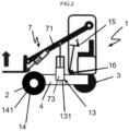
- the invention applies indifferently to a load handling machine 1 18 with arm 71, as illustrated in the figure 2 , or with mast 72, as illustrated in figure 1 .
- This handling machine 1 is a rolling machine.
- This machine 1 comprises two front wheels 2 and one or more rear wheels, shown at 3 in the figures. In the examples shown, only one rear wheel 3 is provided but the invention applies equally to machines comprising one or more rear wheels.
- This machine 1 also includes a so-called rolling chassis 4 equipped with front 2 and rear 3 wheels to form a rolling chassis 4.
- the load handling machine 1 also comprises, at the level of each front wheel 2 driving the movement of the machine, a hydraulic motor 5 or geared motor driving said wheel in rotation.
- This hydraulic motor 5 or geared motor can be common to the two front wheels 2.
- each front wheel 2 can be equipped with a separate hydraulic motor 5, as shown in the figures.
- the load handling machine 1 may comprise one or more hydraulic motors 6 or gear motors driving the rotation of the rear wheel(s) 3 driving the movement of the machine.
- Each hydraulic motor may be a radial piston hydraulic motor.
- Each gear motor can be an orbital or broken axis motor associated with a reduction gear.
- each hydraulic motor is a hydraulic motor with radial pistons.
- These hydraulic motors with radial pistons have the advantage of their small size and the disadvantage of having to go from the "engaged” state to the "disengaged” state when stopped, that is to say at zero speed of the machine 1.
- the load handling machine 1 also comprises a load handling device 7 with a so-called empty state in the absence of load 18 and a loaded state, in the presence of a load 18.
- the load handling device 7 comprises at least one load handling member formed by a load lifting arm 71 or a load lifting mast 72 and at least one displacement drive cylinder of at least a part of said handling member between at least two so-called positions, one low position, the other high position.
- the driving cylinder in movement of the fork-carrying mast, between a high position and a low position and vice versa is shown at 74.
- the arm lifting cylinder for pivoting movement of the arm between a high position and a low position, is shown in 73 in figures.
- This lifting arm 71 can, in the case of a telescopic lifting arm adjustable in length, be equipped with a cylinder for retracting or extending the telescope.
- This lifting arm 71 is equipped, at its free end, with an accessory, such as a bucket, a fork or the like for handling the load 18.
- the machine 1 is also equipped with a reception seat for the driver of the machine arranged inside a cockpit of the machine. Independently of the load handling device 7, this seat and the cabin preferably extend more particularly above the rear wheel 3 of the machine. This implies that in the empty state of the machine 1, the risk of loss of wheel grip is located rather at the front wheels of the machine which support less weight. Likewise, in the case of a pivoting lifting arm, the pivot connection of the arm to the chassis is located in the rear part of the machine taken in relation to the direction of forward movement of the machine.
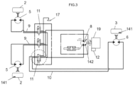
- the load handling machine 1 also includes a hydraulic pump 8 mounted on the rolling chassis 4. This hydraulic pump 8 is driven by a thermal motor 19. This hydraulic pump 8 can be a fixed or variable displacement pump. This second solution corresponds to the one shown.
- the load handling machine 1 also includes a control unit 12. Said control unit is in the form of an electronic and computer system which includes, for example, a microprocessor and a working memory. According to a particular aspect, the control unit 12 can be in the form of a programmable controller. In other words, the functions and steps described can be implemented in the form of a computer program or via hardware components (e.g. programmable gate arrays).
- control unit or its modules can be carried out by instruction sets or computer modules implemented in a processor or controller or be carried out by dedicated electronic components or logic circuit type components.
- programmable or FPGA which is the acronym from the English field-programmable gate array, which literally corresponds to an in-situ programmable gate array
- ASIC application-specific integrated circuit type
- the unit or means or modules of said unit are configured to carry out a given operation, this means that the unit comprises computer instructions and the corresponding execution means which make it possible to carry out said operation and/or or that the unit includes corresponding electronic components.
- the hydraulic pump 8, driven in operation by the thermal motor 19, is capable of supplying fluid, in particular oil, to each hydraulic motor 5, 6.
- Each hydraulic motor 5 or 6 is therefore connected to the hydraulic pump 8 by a fluid circulation circuit equipped with a shutter member 11 mounted movable between at least one open position in which the hydraulic motor or geared motor is able to be powered in fluid by the hydraulic pump 8 and the associated wheel(s) are said to be driving and a closed position in which the associated wheel(s) are said to be non-driving because the associated hydraulic motor is not supplied with fluid by the hydraulic pump.
- the fluid circulation circuit connecting a front wheel 2 to the hydraulic pump 8 is represented at 9 in the figures
- the fluid circulation circuit connecting a rear wheel 3 to the hydraulic pump 8 is represented at 10 in the figures.
- the assembly comprises two front wheels and a rear wheel and therefore two fluid circulation circuits, represented at 9, and a fluid circulation circuit, represented at 10.
- Each fluid circulation circuit comprises a shutter member 11 located presenting, in the examples shown, in the form of an electro-proportional valve, preferably five ways, two positions.
- Each fluid circulation circuit 9 or 10 is distinct from the other fluid circulation circuits, in the zone of the circuit extending between the member 11 for closing the circuit and the hydraulic motors 5 or 6 powered by said circuit.
- This portion of the fluid circulation circuit extending between the shutter member 11 and the hydraulic motor of said circuit each time comprises a forward branch connecting the member 11 for closing a fluid inlet of the hydraulic motor and a return branch connecting the fluid outlet of the hydraulic motor to the member 11 for closing, it being understood that each hydraulic motor comprises at least one inlet and one outlet of fluid.
- Each portion of fluid circulation circuit 9 or 10, arranged between the shutter member 11 and the hydraulic pump 8 is, on the contrary, at least partially common to all of the fluid circulation circuits so that said circuits 9, 10 of fluid circulation are in fluid communication.
- the hydraulic pump 8 supplies input to both the hydraulic motor of one of the circuits and the hydraulic motor of the other of the circuits and the oil returns from the hydraulic motors after passage of the shutter member of said fluid circulation circuits associated with said circuits join to form a common return up to the inlet of the hydraulic pump 8.
- the hydraulic motor of said fluid circulation circuit cannot be powered by the hydraulic pump 8 and the oil inlet and outlet of said hydraulic motor are connected via the shutter member 11 to a fluid reservoir 17.
- two of the paths of the shutter member 11 are used to allow the supply of fluid to the hydraulic motor from the hydraulic pump 8 and the return of fluid from the hydraulic motor to said hydraulic pump in the open position of said member. 11 shutter while in the closed position of said shutter member, any supply of fluid to the hydraulic motor from the hydraulic pump is prevented and a path of the shutter member 11 allows the connection of the inlet and from the outlet of the hydraulic motor to the fluid reservoir 17.
- This fluid reservoir 17 can be at atmospheric pressure or at low pressure, preferably between 10 ⁇ 10 4 and 30 ⁇ 10 4 Pa.
- This solution of a low pressure fluid reservoir can be retained in particular when the hydraulic motors are hydraulic motors with radial pistons to help clutch said motors.
- the direction of rotational drive of the hydraulic pump 8 can be reversed depending on the direction of forward or reverse movement of the machine without changing the design of the rest of the circuit.
- the machine 1 also comprises a system 13 for determining a parameter representative of the empty or loaded state of the load handling device 7.
- This system 13 for determining a parameter representative of the empty or loaded state of the load handling device 7 can affect a large number of shapes.
- the system 13 for determining a parameter representative of the empty or loaded state of the load handling device 7 may comprise at least one pressure sensor 131 arranged at the level of the or at least one of the cylinders 73, 74 for driving movement of at least part of said handling member between the at least two positions.
- this pressure sensor can be arranged at one of the chambers of the jack 73 for lifting the arm 71 or in the retraction or output jack of the telescope in the case of a machine with a telescopic arm 71 or in the one of the chambers of the jack 74 for lifting the mast 72 with a fork in the case of a mast machine.
- the system 13 for determining a parameter representative of the empty or loaded state of the load handling device 7 may comprise at least one member 132, such as a strain gauge, arranged on the machine 1 and configured to detect a deformation and/or a movement of the chassis 4 and/or the load handling device 7 during the transition from the empty state to the load or vice versa of the load handling device 7 .
- the rear wheel can be a pivoting directional wheel.
- the strain gauge can be placed at this rear pivot to measure the reduction in the load at said pivot.
- a strain gauge can be provided to measure the deformation of a part of the structure, namely the chassis and/or the mast of said machine.
- this system 13 for determining a parameter representative of the empty or loaded state of the load handling device 7 makes it possible to determine the presence or absence of a load.
- the control unit 12 is for its part configured to acquire data from the system 13 for determining a parameter representative of the empty or loaded state of the load handling device 7.
- the load handling machine 1 also comprises a first mode of operation, called by propulsion, in which the rear wheel(s) 3 are driven and the front wheels 2 are non-driven, a second mode of operation, called by traction, in in which the front wheel(s) 2 are driven, and the rear wheel(s) 3 are non-driven, that is to say the members 11 for closing the fluid circulation circuits 9 connecting the hydraulic motors 5 of the front wheels to the hydraulic pump 8 are in the open position while the member 12 for closing the fluid circulation circuit 10 connecting the hydraulic motor 6 of the rear wheel to the hydraulic pump is in the closed position.
- the first and second operating modes can be selectively activated.
- the control unit 12 is configured to control the first or second operating mode of the machine 1 based at least on the data of the system 13 for determining a parameter representative of the empty or empty state. load of the load handling device 7.
- the control unit 12 is configured to control the first mode of operation, at least in the empty state of the load handling device 7, and the second mode of operation, at least in the loaded state of the device 7 load handling.
- the first mode of operation is controlled by bringing the member 11 for closing the fluid circulation circuit 10 of the hydraulic motor 6 of the rear wheel 3 into the open position and the member 11 of the rear wheel 3 in the closed position.
- the latter can include a system 14 for determining a parameter representative of the speed of the machine 1 and the control unit 12 is configured to acquire data from the system 14 for determining a parameter representative of the speed of the machine 1.
- this arrangement allows the use of “non-engageable” hydraulic motors while driving. Automatic switching between the first and second operating modes, depending on the presence or absence of load, can only take place when the machine stops.
- This system 14 for determining a parameter representative of the speed of the machine can affect a large number of shapes.
- the system 14 for determining a parameter representative of the speed of the machine can include at least one speed sensor 141 of at least one of the wheels 2, 3 of the machine 1.
- the system 14 for determining a parameter representative of the speed of the machine may comprise at least one sensor 142 for measuring the displacement of the pump 8 in the case of a hydraulic pump 8 with displacement variable.
- the machine 1 can also include a third mode of operation in which the front wheels 2 and the rear wheel(s) 3 are driven.
- the machine 1 comprises a manually operable operating mode selector 15 for switching between the third operating mode and one or other of the first and second operating modes.
- This mode selector 15 is formed for example by a control member, such as a lever placed inside the cockpit, this mode selector 15 being actuated by the driver of the machine 1.
- this third operating mode can be automatically activated.
- This third mode of operation can be used when, for example, the machine is traveling on sloping ground.
- the machine 1 comprises an inclinometer 16 and the control unit 12 is configured to acquire data provided by the inclinometer 16 and to control the third mode at least as a function of the data provided by said inclinometer 16.
- This third mode of operation can also be used when a loss of grip of a drive wheel is detected.
- the machine 1 comprises a system 14 for determining a parameter representative of the speed of the machine comprising at least two speed sensors 141 equipping one, one of the front wheels 2, the other , the or one of the rear wheels 3.
- the control unit 12 is configured to acquire data from said speed sensors 141, and to control the third mode based at least on said data.
- the presence of several speed sensors 141 each equipping a separate wheel makes it possible to determine speed differentials and therefore to easily detect a loss of grip of at least one of the wheels.
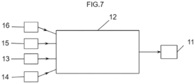
- the control unit 12 is configured to receive as input data from the inclinometer 16, from the system 13 for determining the empty or loaded state of the machine 1, from the system 14 for determining the speed of the machine 1 and the mode selector 15 to act at the output on the shutter members 11 of the fluid circulation circuits 9 and 10, as illustrated in Figure 7 .
- the operation of such a device is as follows. It is assumed that the first operating mode is the operating mode activated by default when the thermal engine 19 is started. As long as the system 13 for determining the empty or loaded state of the machine provides the control unit 12 with information corresponding to the empty state of the machine, the first mode of operation of the machine machine 1 is maintained, unless the driver of the machine activates the mode selector 15 to control the third operating mode of the machine 1 when the latter is present or the inclinometer indicates a steep slope making activation necessary of the third mode of operation or that a loss of grip of the rear drive wheel is detected using the system 14 for determining the speed of the machine.
- This transition from the first to the third mode of operation only takes place if the speed of the machine is zero when the nature of the hydraulic motors requires this type of operation.
- the return to the first operating mode can be carried out manually by actuation of the mode selector 15 or automatically when the slope of the ground on which the machine is traveling is low, that is to say less than one predetermined value or when the loss of grip of the rear drive wheel is no longer present.
- the transition from the first to the second mode of operation can take place when the presence of a load 18 is detected using the data provided by the system 13 for determining the empty or loaded state of said machine.
- the passage may only take place when the speed of the machine is zero if the nature of the hydraulic motors requires this type of operation.
- the second mode of operation of the machine machine is maintained, unless the driver of the machine activates the mode selector 15 to control the third operating mode of the machine 1 when the latter is present or the inclinometer indicates a steep slope making it necessary to activate the third mode of operation or that a loss of grip of the front drive wheels is detected using the system 14 for determining the speed of the machine.
- This transition from the second to the third mode of operation only takes place if the speed of the machine is zero when the nature of the hydraulic motors requires this type of operation.
- the return to the second operating mode can be carried out manually by actuation of the mode selector 15 or automatically when the slope of the ground on which the machine is traveling is low, that is to say lower than a predetermined value or when the loss of grip of the front drive wheels is no longer present.
Landscapes
- Engineering & Computer Science (AREA)
- Transportation (AREA)
- Structural Engineering (AREA)
- Mechanical Engineering (AREA)
- Chemical & Material Sciences (AREA)
- Combustion & Propulsion (AREA)
- Civil Engineering (AREA)
- Life Sciences & Earth Sciences (AREA)
- Geology (AREA)
- General Engineering & Computer Science (AREA)
- Arrangement And Driving Of Transmission Devices (AREA)
Claims (15)
- Lastenfördergerät (1) (18), das mindestens zwei vordere Räder (2), mindestens zwei hintere Räder (3), einen Rahmen (4), bezeichnet als rollender Rahmen, der mit den Rädern (2, 3) ausgestattet ist, einen oder mehrere hydraulische (5) oder Getriebemotoren, um die vorderen Räder (2) in Rotation zu versetzen, einen oder mehrere hydraulische (6) oder Getriebemotoren, um das oder die hinteren Räder (3) in Rotation zu versetzen, und, getragen von dem Rahmen (4), eine Lastenfördervorrichtung (7) mit einem Leerzustand bei Abwesenheit von Last (18) und einem Lastzustand, eine hydraulische Pumpe (8) und eine Steuereinheit (12) umfasst, wobei jeder hydraulische (5, 6) oder Getriebemotor mit der hydraulischen Pumpe (8) verbunden ist, dadurch gekennzeichnet, dass jeder hydraulische (5, 6) oder Getriebemotor mit der hydraulischen Pumpe (8) durch einen Fluidzirkulationskreislauf (9, 10) verbunden ist, der mit einem Absperrorgan (11) ausgestattet ist, das beweglich zwischen mindestens einer offenen Position, in der der hydraulische (5; 6) oder Getriebemotor dazu in der Lage ist, durch die hydraulische Pumpe (8) mit Fluid versorgt zu werden und das oder die Räder (2; 3), die mit dem hydraulischen oder Getriebemotor assoziiert sind, als Antriebsräder bezeichnet werden, und einer geschlossenen Position verbunden ist, in der das oder die Räder (2; 3), die mit dem hydraulischen oder den Getriebemotor assoziiert sind, als Nicht-Antriebsräder bezeichnet werden, wobei die Fluidzirkulationskreisläufe (9, 10) in fluidischer Kommunikation sind, dadurch, dass das Lastenfördergerät (1) mindestens einen ersten Betriebsmodus umfasst, bezeichnet als Schubmodus, in dem das oder die hinteren Räder (3) Antriebsräder sind und die vorderen Räder (2) Nicht-Antriebsräder sind, einen zweiten Betriebsmodus, bezeichnet als Zugmodus, in dem die vorderen Räder Antriebsräder sind und das oder die hinteren Räder Nicht-Antriebsräder sind, und ein System (13) zur Bestimmung eines repräsentativen Parameters des Leer- oder Lastzustands der Lastenfördervorrichtung (7), und dadurch, dass die Steuereinheit (12) konfiguriert ist, um Daten des Systems (13) zur Bestimmung eines repräsentativen Parameters des Leer- oder Lastzustands der Lastenfördervorrichtung (7) zu erfassen und um den ersten und den zweiten Betriebsmodus des Geräts (1) in Funktion mindestens der Daten zu steuern.
- Lastenfördergerät (1) nach Anspruch 1, wobei die Steuereinheit (12) konfiguriert ist, um den ersten Betriebsmodus mindestens im Leerzustand der Lastenfördervorrichtung (7) und den zweiten Betriebsmodus mindestens im Ladezustand der Lastenfördervorrichtung (7) zu steuern.
- Lastenfördergerät (1) nach einem der Ansprüche 1 oder 2, wobei das Gerät (1) ein System (14) zur Bestimmung eines repräsentativen Parameters der Geschwindigkeit des Geräts (1) umfasst, und dadurch, dass die Steuereinheit (12) konfiguriert ist, um Daten des Systems (14) zur Bestimmung eines repräsentativen Parameters der Geschwindigkeit des Geräts (1) zu erfassen.
- Lastenfördergerät (1) nach Anspruch 3, wobei die Steuereinheit (12) konfiguriert ist, um eine Umwandlung zwischen dem ersten Betriebsmodus und dem zweiten Betriebsmodus in Funktion mindestens der Daten des Systems (14) zur Bestimmung eines repräsentativen Parameters der Geschwindigkeit des Geräts zu steuern, und um die Umwandlung zwischen dem ersten Betriebsmodus und dem zweiten Betriebsmodus zu verhindern, wenn die Geschwindigkeit des Geräts nicht null ist.
- Lastenfördergerät (1) nach einem der Ansprüche 3 oder 4, wobei das System (14) zur Bestimmung eines repräsentativen Parameters der Geschwindigkeit des Geräts mindestens einen Geschwindigkeitssensor (141) mindestens eines der Räder (2, 3) des Geräts (1) umfasst.
- Lastenfördergerät (1) nach einem der Ansprüche 3 bis 5, wobei die hydraulische Pumpe (8) eine hydraulische Pumpe mit variablem Hubraum ist, und dadurch, dass das System (14) zur Bestimmung eines repräsentativen Parameters der Geschwindigkeit des Geräts mindestens einen Sensor (142) zur Messung des Hubraums der Pumpe (8) umfasst.
- Lastenfördergerät (1) nach einem der Ansprüche 1 bis 6, wobei die Lastenfördervorrichtung (7) mindestens ein Lastenförderorgan umfasst, das von einem Lastenhebearm (71) oder einem Lastenhebemast (72) und mindestens einem Zylinder (73, 74) zur Verschiebung mindestens einen Teil des Förderorgans zwischen mindestens zwei Positionen zu, von denen die eine als untere Position, die andere als obere Position bezeichnet wird, gebildet ist.
- Lastenfördergerät (1) nach Anspruch 7, wobei das System (13) zur Bestimmung eines repräsentativen Parameters des Leer- oder Lastzustands der Lastenfördervorrichtung (7) mindestens einen Drucksensor (131) umfasst, der auf der Ebene des oder mindestens eines der Zylinder (73, 74) zur Verschiebung mindestens einen Teil des Förderorgans zwischen den mindestens zwei Positionen angeordnet ist.
- Lastenfördergerät (1) nach einem der Ansprüche 1 bis 8, wobei das System (13) zur Bestimmung eines repräsentativen Parameters des Leer- oder Lastzustands der Lastenfördervorrichtung (7) mindestens ein Organ (132) umfasst, wie z. B. einen Dehnungsmesser, der auf dem Gerät (1) angebracht und konfiguriert ist, um eine Verformung und/oder eine Verschiebung des Rahmens (4) und/oder der Lastenfördervorrichtung (7) beim Übergang vom Leerzustand in den Lastzustand oder umgekehrt der Lastenfördervorrichtung (7) nachzuweisen.
- Lastenfördergerät (1) nach einem der Ansprüche 1 bis 9, wobei das Gerät (1) einen dritten Betriebsmodus umfasst, in dem die vorderen Räder (2) und das oder die hinteren Räder (3) Antriebsräder sind.
- Lastenfördergerät (1) nach Anspruch 10, wobei das Gerät (1) einen Betriebsmoduswähler (15) umfasst, der manuell betätigt werden kann, für eine Umwandlung zwischen dem dritten Betriebsmodus und dem einen oder dem anderen des ersten und des zweiten Betriebsmodus.
- Lastenfördergerät (1) nach einem der Ansprüche 10 oder 11, wobei das Gerät (1) einen Neigungsmesser (16) umfasst, und dadurch, dass die Steuereinheit (12) konfiguriert ist, um Daten zu erfassen, die vom Neigungsmesser (16) geliefert werden, und um den dritten Betriebsmodus mindestens in Funktion der Daten zu steuern, die von dem Neigungsmesser (16) geliefert werden.
- Lastenfördergerät (1) nach einem der Ansprüche 10 bis 12, wobei das Gerät (1) ein System (14) zur Bestimmung eines repräsentativen Parameters der Geschwindigkeit des Geräts umfasst, das mindestens zwei Geschwindigkeitssensoren (141) umfasst, von denen einer eines der Vorderräder (2), der andere das oder eines der Hinterräder (3) ausstattet, die Steuereinheit (12) konfiguriert ist, um die Daten der Geschwindigkeitssensoren (141) zu erfassen und um den dritten Betriebsmodus in Funktion mindestens der Daten zu steuern.
- Lastenfördergerät (1) nach einem der Ansprüche 1 bis 13, wobei das Absperrorgan (11) mindestens eines der Fluidzirkulationskreisläufe (9, 10) ein elektroproportionales Ventil mit vorzugsweise 5 Wegen/2 Positionen ist.
- Lastenfördergerät (1) nach einem der Ansprüche 1 bis 14, wobei das Gerät (1) mindestens einen Behälter (17) mit Fluid unter atmosphärischem Druck oder mit Niederdruck umfasst, vorzugsweise im Bereich zwischen 10.104 und 30.104 Pa., und dadurch, dass in der geschlossenen Position des Absperrorgans (11) mindestens einer der Fluidzirkulationskreisläufe (9, 10) des Teils des Fluidzirkulationskreislaufs (9, 10), der sich zwischen dem Absperrorgan (11) und dem hydraulischen oder Getriebemotor (5, 6) erstreckt, der von dem Fluidzirkulationskreislauf (9, 10) versorgt werden kann, mit dem Fluidbehälter (17) verbunden ist.
Applications Claiming Priority (1)
| Application Number | Priority Date | Filing Date | Title |
|---|---|---|---|
| FR2108197A FR3125754B1 (fr) | 2021-07-28 | 2021-07-28 | engin de manutention de charge |
Publications (3)
| Publication Number | Publication Date |
|---|---|
| EP4129727A1 EP4129727A1 (de) | 2023-02-08 |
| EP4129727B1 true EP4129727B1 (de) | 2023-11-22 |
| EP4129727C0 EP4129727C0 (de) | 2023-11-22 |
Family
ID=78049367
Family Applications (1)
| Application Number | Title | Priority Date | Filing Date |
|---|---|---|---|
| EP22185372.4A Active EP4129727B1 (de) | 2021-07-28 | 2022-07-18 | Lastenfördergerät |
Country Status (2)
| Country | Link |
|---|---|
| EP (1) | EP4129727B1 (de) |
| FR (1) | FR3125754B1 (de) |
Cited By (1)
| Publication number | Priority date | Publication date | Assignee | Title |
|---|---|---|---|---|
| AT18551U1 (de) * | 2024-05-29 | 2025-10-15 | Palfinger Ag | Fahrantrieb |
Families Citing this family (1)
| Publication number | Priority date | Publication date | Assignee | Title |
|---|---|---|---|---|
| CN119349481B (zh) * | 2024-12-24 | 2025-05-13 | 中铁电气化局集团西安电气化工程有限公司 | 一种全地形高空作业车动力优化系统及其优化方法 |
Family Cites Families (3)
| Publication number | Priority date | Publication date | Assignee | Title |
|---|---|---|---|---|
| FR2709454B1 (fr) * | 1993-09-03 | 1995-11-24 | Bobard Jeune Sa Ets | Transmission hydrostatique pour véhicules automoteurs et notamment pour machines agricoles. |
| FR2911658B1 (fr) * | 2007-01-22 | 2009-04-24 | Poclain Hydraulics Ind Soc Par | Dispositif de transmission hydrostatique d'un engin. |
| FR2974038B1 (fr) * | 2011-04-18 | 2013-05-10 | Poclain Hydraulics Ind | Dispositif de transmission hydrostatique conferant une motricite elevee |
-
2021
- 2021-07-28 FR FR2108197A patent/FR3125754B1/fr active Active
-
2022
- 2022-07-18 EP EP22185372.4A patent/EP4129727B1/de active Active
Cited By (2)
| Publication number | Priority date | Publication date | Assignee | Title |
|---|---|---|---|---|
| AT18551U1 (de) * | 2024-05-29 | 2025-10-15 | Palfinger Ag | Fahrantrieb |
| EP4656582A1 (de) * | 2024-05-29 | 2025-12-03 | Palfinger AG | Fahrantrieb |
Also Published As
| Publication number | Publication date |
|---|---|
| FR3125754B1 (fr) | 2023-07-14 |
| EP4129727C0 (de) | 2023-11-22 |
| FR3125754A1 (fr) | 2023-02-03 |
| EP4129727A1 (de) | 2023-02-08 |
Similar Documents
| Publication | Publication Date | Title |
|---|---|---|
| EP4129727B1 (de) | Lastenfördergerät | |
| EP2361798B1 (de) | Hydraulisches Übertragungssystem, bei dem die Hauptpumpe ständig in Betrieb sein kann. | |
| EP4408786B1 (de) | Handhabungsmaschine | |
| EP3532331B1 (de) | Hilfsantriebssystem eines anhängers, ausgehend von einem offenen hydraulikkreislauf eines kippmechanismus | |
| EP4183609B1 (de) | Elektrisch angetriebenes hydrostatisches nutzfahrzeug mit hydraulischer unterstützung beim antrieb | |
| EP3532752B1 (de) | Fahrzeugantriebsassistenzsystem mit offenem hydraulikkreis | |
| EP4444599B1 (de) | Handhabungsmaschine mit einer hydraulischen lenkung | |
| EP3976891B1 (de) | Lasthandhabungsfahrzeug | |
| WO2020161409A1 (fr) | Chariot à fourches embarquable sur un véhicule porteur | |
| EP3532366B1 (de) | System zur unterstützung des fahrens eines fahrzeugs mit offenem hydraulikkreis | |
| EP4389683B1 (de) | Lasthandhabungsmaschine | |
| FR3156767A3 (fr) | Engin de manutention | |
| EP4444651B1 (de) | Hublift für in der höhe arbeitende personen | |
| WO2025093833A1 (fr) | Engin de manutention de charge | |
| FR3156438A3 (fr) | Machine de manutention comprenant un vérin hydraulique et procédé de commande correspondant | |
| FR3079246A1 (fr) | Engin de travaux, notamment de chantier, comprenant un bras et un porte-godet | |
| EP3594509A1 (de) | Hubvorrichtung, die einen verbesserten hydraulikkreislauf zur autorisierung einer schnellen kipprückführphase umfasst | |
| FR3132475A3 (fr) | Engin automoteur, tel qu’un engin de manutention de charge | |
| EP4686695A1 (de) | Handhabungsmaschine mit einem magnetventilsystem zur steuerung einer hydraulischen betätigungsvorrichtung eines maschinenorgans | |
| WO2025133513A1 (fr) | Engin de manutention de charge et procede de commande d'un tel engin | |
| FR3038358A3 (fr) | "ensemble de transmission comportant un verin de blocage du passage en marche arriere alimente par une source de pression variable" | |
| FR3146670A1 (fr) | Machine de manutention comprenant un pupitre de commande amovible et procédé de commande de machine correspondant | |
| FR3058101A1 (fr) | Systeme d'assistance a l'entrainement d'un vehicule tout terrain | |
| FR3153314A3 (fr) | Engin de manutention de charge et son procédé de commande | |
| FR3161906A1 (fr) | Machine de manutention équipée d’un système de détection de données d’environnement, et kit de détection correspondant |
Legal Events
| Date | Code | Title | Description |
|---|---|---|---|
| PUAI | Public reference made under article 153(3) epc to a published international application that has entered the european phase |
Free format text: ORIGINAL CODE: 0009012 |
|
| STAA | Information on the status of an ep patent application or granted ep patent |
Free format text: STATUS: THE APPLICATION HAS BEEN PUBLISHED |
|
| AK | Designated contracting states |
Kind code of ref document: A1 Designated state(s): AL AT BE BG CH CY CZ DE DK EE ES FI FR GB GR HR HU IE IS IT LI LT LU LV MC MK MT NL NO PL PT RO RS SE SI SK SM TR |
|
| STAA | Information on the status of an ep patent application or granted ep patent |
Free format text: STATUS: REQUEST FOR EXAMINATION WAS MADE |
|
| 17P | Request for examination filed |
Effective date: 20230206 |
|
| RBV | Designated contracting states (corrected) |
Designated state(s): AL AT BE BG CH CY CZ DE DK EE ES FI FR GB GR HR HU IE IS IT LI LT LU LV MC MK MT NL NO PL PT RO RS SE SI SK SM TR |
|
| GRAP | Despatch of communication of intention to grant a patent |
Free format text: ORIGINAL CODE: EPIDOSNIGR1 |
|
| STAA | Information on the status of an ep patent application or granted ep patent |
Free format text: STATUS: GRANT OF PATENT IS INTENDED |
|
| P01 | Opt-out of the competence of the unified patent court (upc) registered |
Effective date: 20230621 |
|
| RIC1 | Information provided on ipc code assigned before grant |
Ipc: F16H 61/444 20100101ALN20230626BHEP Ipc: F16H 59/52 20060101ALN20230626BHEP Ipc: F16H 61/44 20060101ALN20230626BHEP Ipc: F16H 61/00 20060101ALN20230626BHEP Ipc: B60K 17/10 20060101ALN20230626BHEP Ipc: B60K 7/00 20060101AFI20230626BHEP |
|
| RIC1 | Information provided on ipc code assigned before grant |
Ipc: F16H 61/444 20100101ALN20230630BHEP Ipc: F16H 59/52 20060101ALN20230630BHEP Ipc: F16H 61/44 20060101ALN20230630BHEP Ipc: F16H 61/00 20060101ALN20230630BHEP Ipc: B60K 17/10 20060101ALN20230630BHEP Ipc: B60K 7/00 20060101AFI20230630BHEP |
|
| INTG | Intention to grant announced |
Effective date: 20230717 |
|
| GRAS | Grant fee paid |
Free format text: ORIGINAL CODE: EPIDOSNIGR3 |
|
| GRAA | (expected) grant |
Free format text: ORIGINAL CODE: 0009210 |
|
| STAA | Information on the status of an ep patent application or granted ep patent |
Free format text: STATUS: THE PATENT HAS BEEN GRANTED |
|
| AK | Designated contracting states |
Kind code of ref document: B1 Designated state(s): AL AT BE BG CH CY CZ DE DK EE ES FI FR GB GR HR HU IE IS IT LI LT LU LV MC MK MT NL NO PL PT RO RS SE SI SK SM TR |
|
| REG | Reference to a national code |
Ref country code: GB Ref legal event code: FG4D Free format text: NOT ENGLISH |
|
| REG | Reference to a national code |
Ref country code: CH Ref legal event code: EP |
|
| REG | Reference to a national code |
Ref country code: DE Ref legal event code: R096 Ref document number: 602022001085 Country of ref document: DE |
|
| REG | Reference to a national code |
Ref country code: IE Ref legal event code: FG4D Free format text: LANGUAGE OF EP DOCUMENT: FRENCH |
|
| P04 | Withdrawal of opt-out of the competence of the unified patent court (upc) registered |
Effective date: 20231208 |
|
| U01 | Request for unitary effect filed |
Effective date: 20231207 |
|
| U07 | Unitary effect registered |
Designated state(s): AT BE BG DE DK EE FI FR IT LT LU LV MT NL PT SE SI Effective date: 20231212 |
|
| PG25 | Lapsed in a contracting state [announced via postgrant information from national office to epo] |
Ref country code: GR Free format text: LAPSE BECAUSE OF FAILURE TO SUBMIT A TRANSLATION OF THE DESCRIPTION OR TO PAY THE FEE WITHIN THE PRESCRIBED TIME-LIMIT Effective date: 20240223 |
|
| PG25 | Lapsed in a contracting state [announced via postgrant information from national office to epo] |
Ref country code: IS Free format text: LAPSE BECAUSE OF FAILURE TO SUBMIT A TRANSLATION OF THE DESCRIPTION OR TO PAY THE FEE WITHIN THE PRESCRIBED TIME-LIMIT Effective date: 20240322 |
|
| PG25 | Lapsed in a contracting state [announced via postgrant information from national office to epo] |
Ref country code: ES Free format text: LAPSE BECAUSE OF FAILURE TO SUBMIT A TRANSLATION OF THE DESCRIPTION OR TO PAY THE FEE WITHIN THE PRESCRIBED TIME-LIMIT Effective date: 20231122 |
|
| PG25 | Lapsed in a contracting state [announced via postgrant information from national office to epo] |
Ref country code: IS Free format text: LAPSE BECAUSE OF FAILURE TO SUBMIT A TRANSLATION OF THE DESCRIPTION OR TO PAY THE FEE WITHIN THE PRESCRIBED TIME-LIMIT Effective date: 20240322 Ref country code: GR Free format text: LAPSE BECAUSE OF FAILURE TO SUBMIT A TRANSLATION OF THE DESCRIPTION OR TO PAY THE FEE WITHIN THE PRESCRIBED TIME-LIMIT Effective date: 20240223 Ref country code: ES Free format text: LAPSE BECAUSE OF FAILURE TO SUBMIT A TRANSLATION OF THE DESCRIPTION OR TO PAY THE FEE WITHIN THE PRESCRIBED TIME-LIMIT Effective date: 20231122 |
|
| PG25 | Lapsed in a contracting state [announced via postgrant information from national office to epo] |
Ref country code: RS Free format text: LAPSE BECAUSE OF FAILURE TO SUBMIT A TRANSLATION OF THE DESCRIPTION OR TO PAY THE FEE WITHIN THE PRESCRIBED TIME-LIMIT Effective date: 20231122 Ref country code: PL Free format text: LAPSE BECAUSE OF FAILURE TO SUBMIT A TRANSLATION OF THE DESCRIPTION OR TO PAY THE FEE WITHIN THE PRESCRIBED TIME-LIMIT Effective date: 20231122 Ref country code: NO Free format text: LAPSE BECAUSE OF FAILURE TO SUBMIT A TRANSLATION OF THE DESCRIPTION OR TO PAY THE FEE WITHIN THE PRESCRIBED TIME-LIMIT Effective date: 20240222 Ref country code: HR Free format text: LAPSE BECAUSE OF FAILURE TO SUBMIT A TRANSLATION OF THE DESCRIPTION OR TO PAY THE FEE WITHIN THE PRESCRIBED TIME-LIMIT Effective date: 20231122 |
|
| PG25 | Lapsed in a contracting state [announced via postgrant information from national office to epo] |
Ref country code: CZ Free format text: LAPSE BECAUSE OF FAILURE TO SUBMIT A TRANSLATION OF THE DESCRIPTION OR TO PAY THE FEE WITHIN THE PRESCRIBED TIME-LIMIT Effective date: 20231122 |
|
| PG25 | Lapsed in a contracting state [announced via postgrant information from national office to epo] |
Ref country code: SK Free format text: LAPSE BECAUSE OF FAILURE TO SUBMIT A TRANSLATION OF THE DESCRIPTION OR TO PAY THE FEE WITHIN THE PRESCRIBED TIME-LIMIT Effective date: 20231122 |
|
| PG25 | Lapsed in a contracting state [announced via postgrant information from national office to epo] |
Ref country code: SM Free format text: LAPSE BECAUSE OF FAILURE TO SUBMIT A TRANSLATION OF THE DESCRIPTION OR TO PAY THE FEE WITHIN THE PRESCRIBED TIME-LIMIT Effective date: 20231122 Ref country code: SK Free format text: LAPSE BECAUSE OF FAILURE TO SUBMIT A TRANSLATION OF THE DESCRIPTION OR TO PAY THE FEE WITHIN THE PRESCRIBED TIME-LIMIT Effective date: 20231122 Ref country code: RO Free format text: LAPSE BECAUSE OF FAILURE TO SUBMIT A TRANSLATION OF THE DESCRIPTION OR TO PAY THE FEE WITHIN THE PRESCRIBED TIME-LIMIT Effective date: 20231122 Ref country code: CZ Free format text: LAPSE BECAUSE OF FAILURE TO SUBMIT A TRANSLATION OF THE DESCRIPTION OR TO PAY THE FEE WITHIN THE PRESCRIBED TIME-LIMIT Effective date: 20231122 |
|
| REG | Reference to a national code |
Ref country code: DE Ref legal event code: R097 Ref document number: 602022001085 Country of ref document: DE |
|
| U20 | Renewal fee for the european patent with unitary effect paid |
Year of fee payment: 3 Effective date: 20240724 |
|
| PLBE | No opposition filed within time limit |
Free format text: ORIGINAL CODE: 0009261 |
|
| STAA | Information on the status of an ep patent application or granted ep patent |
Free format text: STATUS: NO OPPOSITION FILED WITHIN TIME LIMIT |
|
| 26N | No opposition filed |
Effective date: 20240823 |
|
| P05 | Withdrawal of opt-out of the competence of the unified patent court (upc) changed |
Free format text: CASE NUMBER: APP_592909/2023 Effective date: 20231212 |
|
| PG25 | Lapsed in a contracting state [announced via postgrant information from national office to epo] |
Ref country code: MC Free format text: LAPSE BECAUSE OF FAILURE TO SUBMIT A TRANSLATION OF THE DESCRIPTION OR TO PAY THE FEE WITHIN THE PRESCRIBED TIME-LIMIT Effective date: 20231122 |
|
| PG25 | Lapsed in a contracting state [announced via postgrant information from national office to epo] |
Ref country code: IE Free format text: LAPSE BECAUSE OF NON-PAYMENT OF DUE FEES Effective date: 20240718 |
|
| U20 | Renewal fee for the european patent with unitary effect paid |
Year of fee payment: 4 Effective date: 20250728 |
|
| PG25 | Lapsed in a contracting state [announced via postgrant information from national office to epo] |
Ref country code: CY Free format text: LAPSE BECAUSE OF FAILURE TO SUBMIT A TRANSLATION OF THE DESCRIPTION OR TO PAY THE FEE WITHIN THE PRESCRIBED TIME-LIMIT; INVALID AB INITIO Effective date: 20220718 |
|
| REG | Reference to a national code |
Ref country code: CH Ref legal event code: H13 Free format text: ST27 STATUS EVENT CODE: U-0-0-H10-H13 (AS PROVIDED BY THE NATIONAL OFFICE) Effective date: 20260224 |
|
| PG25 | Lapsed in a contracting state [announced via postgrant information from national office to epo] |
Ref country code: HU Free format text: LAPSE BECAUSE OF FAILURE TO SUBMIT A TRANSLATION OF THE DESCRIPTION OR TO PAY THE FEE WITHIN THE PRESCRIBED TIME-LIMIT; INVALID AB INITIO Effective date: 20220718 |
|
| PG25 | Lapsed in a contracting state [announced via postgrant information from national office to epo] |
Ref country code: CH Free format text: LAPSE BECAUSE OF NON-PAYMENT OF DUE FEES Effective date: 20250731 |