EP4129692A1 - Liquid discharge structure, liquid discharge head, and liquid discharge apparatus - Google Patents
Liquid discharge structure, liquid discharge head, and liquid discharge apparatus Download PDFInfo
- Publication number
- EP4129692A1 EP4129692A1 EP21781027.4A EP21781027A EP4129692A1 EP 4129692 A1 EP4129692 A1 EP 4129692A1 EP 21781027 A EP21781027 A EP 21781027A EP 4129692 A1 EP4129692 A1 EP 4129692A1
- Authority
- EP
- European Patent Office
- Prior art keywords
- layer
- liquid
- jetting
- nozzle
- flow passage
- Prior art date
- Legal status (The legal status is an assumption and is not a legal conclusion. Google has not performed a legal analysis and makes no representation as to the accuracy of the status listed.)
- Granted
Links
Images

Classifications
-
- B—PERFORMING OPERATIONS; TRANSPORTING
- B41—PRINTING; LINING MACHINES; TYPEWRITERS; STAMPS
- B41J—TYPEWRITERS; SELECTIVE PRINTING MECHANISMS, i.e. MECHANISMS PRINTING OTHERWISE THAN FROM A FORME; CORRECTION OF TYPOGRAPHICAL ERRORS
- B41J2/00—Typewriters or selective printing mechanisms characterised by the printing or marking process for which they are designed
- B41J2/005—Typewriters or selective printing mechanisms characterised by the printing or marking process for which they are designed characterised by bringing liquid or particles selectively into contact with a printing material
- B41J2/01—Ink jet
- B41J2/135—Nozzles
- B41J2/16—Production of nozzles
- B41J2/1606—Coating the nozzle area or the ink chamber
-
- B—PERFORMING OPERATIONS; TRANSPORTING
- B41—PRINTING; LINING MACHINES; TYPEWRITERS; STAMPS
- B41J—TYPEWRITERS; SELECTIVE PRINTING MECHANISMS, i.e. MECHANISMS PRINTING OTHERWISE THAN FROM A FORME; CORRECTION OF TYPOGRAPHICAL ERRORS
- B41J2/00—Typewriters or selective printing mechanisms characterised by the printing or marking process for which they are designed
- B41J2/005—Typewriters or selective printing mechanisms characterised by the printing or marking process for which they are designed characterised by bringing liquid or particles selectively into contact with a printing material
- B41J2/01—Ink jet
- B41J2/135—Nozzles
- B41J2/14—Structure thereof only for on-demand ink jet heads
- B41J2/14201—Structure of print heads with piezoelectric elements
-
- B—PERFORMING OPERATIONS; TRANSPORTING
- B41—PRINTING; LINING MACHINES; TYPEWRITERS; STAMPS
- B41J—TYPEWRITERS; SELECTIVE PRINTING MECHANISMS, i.e. MECHANISMS PRINTING OTHERWISE THAN FROM A FORME; CORRECTION OF TYPOGRAPHICAL ERRORS
- B41J2/00—Typewriters or selective printing mechanisms characterised by the printing or marking process for which they are designed
- B41J2/005—Typewriters or selective printing mechanisms characterised by the printing or marking process for which they are designed characterised by bringing liquid or particles selectively into contact with a printing material
- B41J2/01—Ink jet
- B41J2/135—Nozzles
- B41J2/16—Production of nozzles
- B41J2/1607—Production of print heads with piezoelectric elements
- B41J2/161—Production of print heads with piezoelectric elements of film type, deformed by bending and disposed on a diaphragm
-
- B—PERFORMING OPERATIONS; TRANSPORTING
- B41—PRINTING; LINING MACHINES; TYPEWRITERS; STAMPS
- B41J—TYPEWRITERS; SELECTIVE PRINTING MECHANISMS, i.e. MECHANISMS PRINTING OTHERWISE THAN FROM A FORME; CORRECTION OF TYPOGRAPHICAL ERRORS
- B41J2/00—Typewriters or selective printing mechanisms characterised by the printing or marking process for which they are designed
- B41J2/005—Typewriters or selective printing mechanisms characterised by the printing or marking process for which they are designed characterised by bringing liquid or particles selectively into contact with a printing material
- B41J2/01—Ink jet
- B41J2/135—Nozzles
- B41J2/16—Production of nozzles
- B41J2/1621—Manufacturing processes
- B41J2/1623—Manufacturing processes bonding and adhesion
-
- B—PERFORMING OPERATIONS; TRANSPORTING
- B41—PRINTING; LINING MACHINES; TYPEWRITERS; STAMPS
- B41J—TYPEWRITERS; SELECTIVE PRINTING MECHANISMS, i.e. MECHANISMS PRINTING OTHERWISE THAN FROM A FORME; CORRECTION OF TYPOGRAPHICAL ERRORS
- B41J2/00—Typewriters or selective printing mechanisms characterised by the printing or marking process for which they are designed
- B41J2/005—Typewriters or selective printing mechanisms characterised by the printing or marking process for which they are designed characterised by bringing liquid or particles selectively into contact with a printing material
- B41J2/01—Ink jet
- B41J2/135—Nozzles
- B41J2/16—Production of nozzles
- B41J2/1621—Manufacturing processes
- B41J2/1626—Manufacturing processes etching
- B41J2/1628—Manufacturing processes etching dry etching
-
- B—PERFORMING OPERATIONS; TRANSPORTING
- B41—PRINTING; LINING MACHINES; TYPEWRITERS; STAMPS
- B41J—TYPEWRITERS; SELECTIVE PRINTING MECHANISMS, i.e. MECHANISMS PRINTING OTHERWISE THAN FROM A FORME; CORRECTION OF TYPOGRAPHICAL ERRORS
- B41J2/00—Typewriters or selective printing mechanisms characterised by the printing or marking process for which they are designed
- B41J2/005—Typewriters or selective printing mechanisms characterised by the printing or marking process for which they are designed characterised by bringing liquid or particles selectively into contact with a printing material
- B41J2/01—Ink jet
- B41J2/135—Nozzles
- B41J2/16—Production of nozzles
- B41J2/1621—Manufacturing processes
- B41J2/164—Manufacturing processes thin film formation
- B41J2/1642—Manufacturing processes thin film formation thin film formation by CVD [chemical vapor deposition]
-
- B—PERFORMING OPERATIONS; TRANSPORTING
- B41—PRINTING; LINING MACHINES; TYPEWRITERS; STAMPS
- B41J—TYPEWRITERS; SELECTIVE PRINTING MECHANISMS, i.e. MECHANISMS PRINTING OTHERWISE THAN FROM A FORME; CORRECTION OF TYPOGRAPHICAL ERRORS
- B41J2/00—Typewriters or selective printing mechanisms characterised by the printing or marking process for which they are designed
- B41J2/005—Typewriters or selective printing mechanisms characterised by the printing or marking process for which they are designed characterised by bringing liquid or particles selectively into contact with a printing material
- B41J2/01—Ink jet
- B41J2/135—Nozzles
- B41J2/16—Production of nozzles
- B41J2/1621—Manufacturing processes
- B41J2/164—Manufacturing processes thin film formation
- B41J2/1646—Manufacturing processes thin film formation thin film formation by sputtering
-
- B—PERFORMING OPERATIONS; TRANSPORTING
- B41—PRINTING; LINING MACHINES; TYPEWRITERS; STAMPS
- B41J—TYPEWRITERS; SELECTIVE PRINTING MECHANISMS, i.e. MECHANISMS PRINTING OTHERWISE THAN FROM A FORME; CORRECTION OF TYPOGRAPHICAL ERRORS
- B41J2/00—Typewriters or selective printing mechanisms characterised by the printing or marking process for which they are designed
- B41J2/005—Typewriters or selective printing mechanisms characterised by the printing or marking process for which they are designed characterised by bringing liquid or particles selectively into contact with a printing material
- B41J2/01—Ink jet
- B41J2/17—Ink jet characterised by ink handling
- B41J2/18—Ink recirculation systems
-
- B—PERFORMING OPERATIONS; TRANSPORTING
- B41—PRINTING; LINING MACHINES; TYPEWRITERS; STAMPS
- B41J—TYPEWRITERS; SELECTIVE PRINTING MECHANISMS, i.e. MECHANISMS PRINTING OTHERWISE THAN FROM A FORME; CORRECTION OF TYPOGRAPHICAL ERRORS
- B41J2/00—Typewriters or selective printing mechanisms characterised by the printing or marking process for which they are designed
- B41J2/005—Typewriters or selective printing mechanisms characterised by the printing or marking process for which they are designed characterised by bringing liquid or particles selectively into contact with a printing material
- B41J2/01—Ink jet
- B41J2/135—Nozzles
- B41J2/14—Structure thereof only for on-demand ink jet heads
- B41J2/14201—Structure of print heads with piezoelectric elements
- B41J2002/14306—Flow passage between manifold and chamber
-
- B—PERFORMING OPERATIONS; TRANSPORTING
- B41—PRINTING; LINING MACHINES; TYPEWRITERS; STAMPS
- B41J—TYPEWRITERS; SELECTIVE PRINTING MECHANISMS, i.e. MECHANISMS PRINTING OTHERWISE THAN FROM A FORME; CORRECTION OF TYPOGRAPHICAL ERRORS
- B41J2202/00—Embodiments of or processes related to ink-jet or thermal heads
- B41J2202/01—Embodiments of or processes related to ink-jet heads
- B41J2202/03—Specific materials used
Definitions
- the present disclosure relates to a liquid jetting structure, a liquid jetting head, and a liquid jetting device.
- a liquid jetting head represented by an ink jet head mounted on an ink jet recording device has a nozzle for jetting a liquid.
- the liquid is supplied from a liquid supply chamber to a liquid flow passage and is jetted from a nozzle hole formed in the nozzle connected to the liquid flow passage.
- JP2009-184176A discloses a liquid droplet jetting head comprising a nozzle substrate comprising a plurality of nozzle holes comprising at least a nozzle portion that jets liquid droplets and an introduction portion having a larger cross-sectional area than the nozzle portion and provided coaxially with the nozzle portion, in which the nozzle substrate has a plurality of layers of jetting liquid-resistant protective films formed at least on an inner wall of the nozzle holes.
- JP2014-124876A discloses a liquid droplet ejection head comprising a nozzle plate in which a plurality of nozzle openings are provided on a silicon substrate, a hafnium oxide film or a zirconium oxide film formed by atomic layer deposition is provided on both surfaces of the silicon substrate and a nozzle opening inner surface, and a plasma polymerization film of a silicone material is provided on the hafnium oxide film or the zirconium oxide film on a jetting surface.
- JP2009-220471A discloses a liquid jetting head that includes a nozzle plate formed with nozzle holes for jetting liquid droplets and jets a liquid from the nozzle holes by pressurizing the liquid in a liquid chamber communicating with the nozzle holes, in which titanium or a titanium oxide film is formed on a jetting side on a surface of the nozzle plate, a silicon oxide film is formed on the titanium or titanium oxide film, a water-repellent layer is formed on the silicon oxide film, a silicon oxide film is formed on a liquid chamber side and an inner wall of the nozzle hole on the surface of the nozzle plate, the titanium or titanium oxide film is covered with a silicon oxide film, an interface between the silicon oxide film and the titanium or titanium oxide film is not exposed on a liquid contact surface.
- a component contained in a liquid adhere to a jetting surface of a liquid jetting head as foreign matter because of drying after the liquid is jetted.
- jetting failure is likely to occur. Therefore, in a liquid jetting device, foreign matter can be removed by periodically wiping the jetting surface of the liquid jetting head.
- durability of the jetting surface of the liquid jetting head may decrease by wiping, and durability against wiping (hereinafter, also referred to as "wipe resistance”) is required.
- alkali resistance durability against alkali
- JP2009-184176A a silicon oxide film, a metal oxide film, and a water-repellent film are provided in this order on the jetting surface. Since adhesiveness between the water-repellent film and the metal oxide film is insufficient, the jetting surface is considered to be inferior in wipe resistance.
- JP2014-124876A a hafnium oxide film or a zirconium oxide film, a plasma polymerization film of a silicone material, and a liquid-repellent film are provided in this order on the jetting surface.
- the plasma polymerization film has few bonding points and many pinholes. Therefore, adhesiveness between the liquid-repellent film and the plasma polymerization film is insufficient, and the jetting surface is considered to be inferior in wipe resistance.
- JP2009-220471A titanium or a titanium oxide film and a silicon oxide film are provided in this order on a part of the inner wall of the nozzle hole.
- the silicon oxide film is provided on the liquid chamber side on the surface of the nozzle plate, and it is considered to be inferior in alkali resistance.
- the present disclosure has been made in view of such circumstances, and an object to be achieved by an embodiment of the present invention is to provide a liquid jetting structure, a liquid jetting head, and a liquid jetting device, in which a jetting surface is excellent in wipe resistance and the jetting surface and a liquid flow passage are excellent in alkali resistance.
- the present disclosure includes the following aspects.
- a liquid jetting structure a liquid jetting head, and a liquid jetting device, in which a jetting surface is excellent in wipe resistance and the jetting surface and an internal flow passage are excellent in alkali resistance.
- liquid jetting structure a liquid jetting head, and a liquid jetting device of the present disclosure will be described in detail.
- a numerical range shown using “to” indicates a range including the numerical values described before and after “to” as a lower limit value and an upper limit value.
- the amount of the respective components in the composition indicates the total amount of the plurality of substances present in the composition unless otherwise specified.
- an upper limit value or a lower limit value described in a certain numerical range may be replaced with an upper limit value or a lower limit value in another numerical range described in a stepwise manner or a value described in an example.
- step denotes not only an individual step but also a step which is not clearly distinguishable from another step as long as an effect expected from the step can be achieved.
- liquid-repellent layer refers to a layer having a contact angle with water of 60° or more.
- the contact angle with water is a value measured under the condition of 25°C by using a contact angle meter, for example, a fully automatic contact angle meter (product name "DM-701", manufactured by Kyowa Interface Science Co., Ltd.).
- internal flow passage means a path through which a liquid passes, which is formed inside the liquid jetting structure. That is, the term “internal flow passage” is a concept including a nozzle formed on a nozzle substrate and a liquid flow passage formed on a flow passage substrate.
- jetting surface means a surface of the nozzle substrate on a side where the liquid is jetted in the liquid jetting structure.
- the term “inner wall of the liquid flow passage” means a surface of the flow passage substrate on a side where the liquid flow passage is formed.
- the “inner wall of the nozzle” means a surface of the nozzle substrate on a side where the nozzle is formed.
- a liquid jetting structure of the present disclosure comprises a nozzle substrate on which a nozzle for jetting a liquid is formed; and a flow passage substrate on which a liquid flow passage communicating with the nozzle is formed.
- a first layer, a second layer, and a liquid-repellent layer are provided in this order on a jetting surface of the nozzle substrate, and the first layer and the second layer are provided in this order on an inner wall of the liquid flow passage.
- the first layer is a layer containing at least one selected from the group consisting of tantalum oxide, zirconium oxide, titanium oxide, and hafnium oxide.
- the second layer is a layer containing at least one selected from the group consisting of SiO 2 , SiC, SiN, SiCN, and SiON.
- Providing the first layer, the second layer, and the liquid-repellent layer in this order on the jetting surface of the nozzle substrate means that the liquid-repellent layer is located on an outermost surface of the nozzle substrate. That is, the liquid-repellent layer is the outermost layer among a plurality of layers provided on the nozzle substrate. Since the liquid jetting structure of the present disclosure has the liquid-repellent layer on the outermost surface of the nozzle substrate, the liquid jetting structure is excellent in antifouling property on the jetting surface.
- the liquid jetting structure of the present disclosure has a second layer which is a layer containing at least one selected from the group consisting of SiO 2 , SiC, SiN, SiCN, and SiON under the liquid-repellent layer which is the outermost layer in the nozzle substrate.
- a layer containing at least one selected from the group consisting of SiO 2 , SiC, SiN, SiCN, and SiON has high adhesiveness to the liquid-repellent layer and excellent wipe resistance of the jetting surface.
- the liquid jetting structure of the present disclosure has a first layer which is a layer containing at least one selected from the group consisting of tantalum oxide, zirconium oxide, titanium oxide, and hafnium oxide under the second layer in the nozzle substrate, the nozzle, and the liquid flow passage. At least one selected from the group consisting of tantalum oxide, zirconium oxide, titanium oxide, and hafnium oxide is excellent in alkali resistance. Therefore, in a case where an alkaline liquid permeates into the second layer due to a long period of use, the presence of the first layer makes it possible to maintain the alkali resistance of the jetting surface and the internal flow passage.
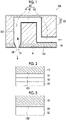
- Fig. 1 is a cross-sectional view showing an embodiment of the liquid jetting structure of the present disclosure.
- a liquid jetting structure 100 comprises a nozzle substrate 10 on which a nozzle 30 for jetting a liquid is formed, and a flow passage substrate 20 on which a liquid flow passage 40 communicating with the nozzle 30 is formed. It is preferable that the nozzle substrate 10 and the flow passage substrate 20 are bonded by adhesion or the like.
- a type of the liquid supplied to the liquid jetting structure 100 is not particularly limited.
- the liquid jetting structure 100 is used for a liquid jetting head described below, and by incorporating the liquid jetting head into a liquid jetting device described below, fine liquid droplets can be jetted from the nozzle 30. It is preferable to use ink as a liquid, and an image can be recorded by jetting fine ink droplets onto the substrate.
- the ink for recording an image is, for example, a liquid containing a coloring material, a solvent, and a surfactant.
- a pretreatment liquid may be jetted onto the substrate in advance before the ink is jetted onto the substrate, or a posttreatment liquid may be jetted after the ink is jetted. Therefore, examples of the liquid supplied to the liquid jetting structure 100 include a pretreatment liquid and a posttreatment liquid in addition to the ink.
- the pretreatment liquid and the posttreatment liquid are usually colorless liquids containing no coloring material.
- the liquid supplied to the liquid jetting structure 100 may be an acidic liquid or an alkaline liquid.
- the liquid jetting structure 100 is suitable for an alkaline liquid because the jetting surface and the inside of the flow passage are excellent in alkali resistance.
- the liquid jetting structure 100 is suitable for a liquid having a pH of 8 to 11.
- the pH is a value measured at 25°C using a pH meter, for example, a value measured using a product name "handy pH meter" manufactured by Sato Keiryoki Mfg. Co., Ltd.
- the nozzle substrate 10 is, for example, a substrate made of silicon, and may be a single crystal silicon substrate or a polycrystal silicon substrate.
- the nozzle 30 for jetting a liquid is formed on the nozzle substrate 10.
- the nozzle 30 is a hole penetrating the nozzle substrate 10, and is formed by, for example, dry etching. It is preferable that a plurality of the nozzles 30 are formed on the nozzle substrate 10.
- a shape of the nozzle 30 is not particularly limited, but from the viewpoint of controlling a jetting direction of the liquid, it is preferable that the nozzle 30 has a tapered shape whose diameter decreases toward the jetting direction of the liquid.
- a hole diameter on a side where the liquid of the nozzle 30 is jetted, that is, a hole diameter of a nozzle opening 31 can be appropriately adjusted. In a case where the liquid jetting structure 100 is used for the inkjet head, the hole diameter of the nozzle opening 31 is, for example, 10 ⁇ m to 30 ⁇ m.
- a thickness of the nozzle substrate 10 corresponds to a length of the nozzle 30, and is preferably 10 ⁇ m to 100 ⁇ m, and more preferably 20 ⁇ m to 60 ⁇ m.
- Fig. 2 is an enlarged view of a broken line frame A in Fig. 1 .
- a first layer 51, a second layer 52, and a liquid-repellent layer 53 are provided in this order on a jetting surface 101 of the nozzle substrate 10.
- the first layer 51 is a layer containing at least one selected from the group consisting of tantalum oxide, zirconium oxide, titanium oxide, and hafnium oxide, and is preferably a layer of tantalum oxide, zirconium oxide, or hafnium oxide.
- At least one (preferably tantalum oxide, zirconium oxide, or hafnium oxide) selected from the group consisting of tantalum oxide, zirconium oxide, titanium oxide, and hafnium oxide is excellent in alkali resistance. Therefore, in a case where an alkaline liquid permeates into the liquid-repellent layer and the second layer provided on the jetting surface of the nozzle substrate due to a long period of use, the presence of the first layer makes it possible to maintain the alkali resistance of the jetting surface.
- a thickness of the first layer 51 is preferably 3 nm to 70 nm, more preferably 10 nm to 50 nm, and still more preferably 20 nm to 50 nm.
- the thickness of the first layer 51 is 3 nm or more, the alkaline liquid is less likely to permeate into the first layer 51, and the wipe resistance and the alkali resistance of the jetting surface are excellent.
- the thickness of the first layer 51 is 70 nm or less, defects are less likely to occur in the layer, and the wipe resistance and the alkali resistance of the jetting surface are excellent. From the viewpoint of productivity, the thickness of the first layer 51 is preferably 50 nm or less.
- the second layer 52 is a layer containing at least one selected from the group consisting of SiO 2 , SiC, SiN, SiCN, and SiON, and is preferably a SiO 2 layer.
- a layer (preferably SiO 2 layer) containing at least one selected from the group consisting of SiO 2 , SiC, SiN, SiCN, and SiON has high adhesiveness to the liquid-repellent layer 53. Therefore, the alkaline liquid is less likely to permeate into the liquid-repellent layer 53 and the second layer 52, and the wipe resistance and the alkali resistance of the jetting surface are excellent.
- a thickness of the second layer 52 is preferably 0.3 nm to 120 nm, more preferably 0.3 nm to 3 nm or 10 nm to 100 nm, still more preferably 0.3 nm to 3 nm, and still more preferably 0.5 nm to 2 nm.
- the thickness of the second layer 52 is 0.3 nm to 3 nm or 10 nm to 100 nm, the adhesiveness between the second layer 52 and the liquid-repellent layer 53 is enhanced, and the wipe resistance and the alkali resistance of the jetting surface are excellent.
- a ratio of the thickness of the second layer 52 to the thickness of the first layer 51 is preferably 0.006 or more and 6 or less, more preferably 0.006 or more and 0.3 or less, still more preferably 0.01 or more and 0.15 or less, and still more preferably 0.01 or more and 0.1 or less.
- the ratio of the thickness of the second layer 52 to the thickness of the first layer 51 is 0.006 or more and 0.3 or less, the alkaline liquid is less likely to permeate into the first layer 51, and the wipe resistance and the alkali resistance of the jetting surface are excellent.
- the adhesiveness between the first layer 51 and the second layer 52 is high, and the wipe resistance and the alkali resistance of the jetting surface are excellent.
- the liquid-repellent layer 53 is a layer having a contact angle with water of 60° or more.
- the contact angle of the liquid-repellent layer 53 with water is preferably 70° or more, and more preferably 80° or more. Since the liquid-repellent layer 53 is provided on the outermost surface of the nozzle substrate 10, the wipe resistance of the jetting surface is excellent.
- the liquid-repellent layer 53 preferably contains a fluorine-containing compound, and more preferably contains a compound having a perfluoropolyether structure.
- a compound having a perfluoropolyether structure has a highly flexible and dense molecular structure. Therefore, it is possible to suppress the permeation of the alkaline liquid into the inside of the liquid-repellent layer 53, and the alkali resistance is excellent. Since the perfluoropolyether structure has a high fluorine content, fluorine atoms are likely to remain on a surface of the liquid-repellent layer 53 even after wiping, and the contact angle is less likely to decrease. That is, the wipe resistance of the jetting surface is excellent.
- the liquid-repellent layer 53 is preferably formed using silicon coupling agent, and more preferably formed using a silicon coupling agent having a perfluoropolyether structure. That is, the liquid-repellent layer 53 is still more preferably a silicon compound having a perfluoropolyether structure.
- perfluoropolyether structure examples include structures represented by Formulas 1 to 3.
- the perfluoropolyether structure is preferably a structure represented by Formula 1. CF 3 O-(CF 2 O) n -(CF 2 CF 2 O) m - ⁇ ... (1)
- n represents an integer of 0 to 300
- m + n is 1 or more. * indicates a bonding position to other structures in the compound.
- m represents preferably an integer of 0 to 50 and more preferably an integer of 1 to 50.
- n represents preferably an integer of 0 to 50 and more preferably an integer of 1 to 50.
- n represents an integer of 1 to 100. * indicates a bonding position to other structures in the compound. CF 3 -(CF 2 O) n - ⁇ ... (3)
- n represents an integer of 1 to 300. * indicates a bonding position to other structures in the compound.
- a thickness of the liquid-repellent layer 53 is preferably 3 nm to 12 nm, and more preferably 3 nm to 8 nm. In a case where the thickness of the liquid-repellent layer 53 is 3 nm or more, the wipe resistance is improved. On the other hand, in a case where the thickness of the liquid-repellent layer 53 is 12 nm or less, aggregates derived from components constituting the liquid-repellent layer 53 are less likely to adhere to the surface of the liquid-repellent layer 53, and insertion of the aggregates into the nozzle 30 can be suppressed. As a result, the deterioration of the liquid jettability is suppressed.
- Fig. 3 is an enlarged view of a broken line frame B in Fig. 1 .
- the liquid jetting structure 100 has a first layer 51 and a second layer 52 on an inner wall 102 of the nozzle 30 in this order.
- the first layer 51 and the second layer 52 provided on the inner wall 102 of the nozzle 30 are the same as the first layer 51 and the second layer 52 provided on the jetting surface 101 of the nozzle substrate 10.
- the liquid jetting structure 100 has the first layer 51 and the second layer 52 on the inner wall 102 of the nozzle 30 in this order, the inner wall 102 of the nozzle 30 has excellent alkali resistance.
- the flow passage substrate 20 is, for example, a substrate made of silicon, and may be a single crystal silicon substrate or a polycrystal silicon substrate. As shown in Fig. 1 , the flow passage substrate 20 is composed of a wall member 21 and a lid member 22, and the wall member 21 and the lid member 22 are preferably bonded by adhesion or the like.
- the liquid flow passage 40 communicating with the nozzle 30 is formed in the flow passage substrate 20.
- the liquid flow passage 40 includes a nozzle communication path 41, a pressure chamber 42, and a liquid supply path 43.
- the nozzle communication path 41 is a flow passage connecting the pressure chamber 42 and the nozzle 30.
- the nozzle communication path 41 is preferably linear in a cross section.
- the pressure chamber 42 is a flow passage whose volume changes by application of a driving voltage in a case where the liquid jetting structure 100 is used for a liquid jetting head described below.
- a planar shape of the pressure chamber 42 is, for example, a substantially square shape in a case where the liquid jetting structure 100 is viewed in a plan view, and has an outlet of the liquid to the nozzle communication path 41 at one of both corner portions on the diagonal line and the liquid supply path 43 as an inlet of the liquid at the other.
- the planar shape of the pressure chamber 42 is not limited to a substantially square shape, and may be a rectangle, a trapezoid, or the like.
- the liquid supply path 43 is a flow passage that is connected to a liquid tank (not shown) in a case where the liquid jetting structure 100 is incorporated into a liquid jetting device described below.
- a liquid is supplied from the liquid tank to the pressure chamber 42 via the liquid supply path 43.
- the arrows in the figure indicate a direction in which the liquid flows.
- the liquid jetting structure 100 has a first layer 51 and a second layer 52 on an inner wall 201 of the liquid flow passage 40 in this order, as on the inner wall 102 of the nozzle 30 shown in Fig. 3 .
- the first layer 51 and the second layer 52 provided on the inner wall 201 of the liquid flow passage 40 are the same as the first layer 51 and the second layer 52 provided on the jetting surface 101 of the nozzle substrate 10.
- the inner wall 201 of the liquid flow passage 40 has a surface of the wall member 21 on a side where the liquid flow passage 40 is formed, a surface of the lid member 22 on a side where the liquid flow passage 40 is formed, and a surface of the nozzle substrate 10 on a side where the liquid flow passage 40 is formed.
- the liquid jetting structure 100 has the first layer 51 and the second layer 52 on the inner wall 201 of the liquid flow passage 40 in this order, the inner wall 201 of the liquid flow passage 40 has excellent alkali resistance.
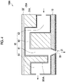
- the structure of the flow passage substrate 20 may be, for example, the structure shown in Fig. 4 .
- Fig. 4 is a schematic cross-sectional view showing a modification example of the liquid jetting structure of the present disclosure.
- a liquid jetting structure 100A comprises a nozzle substrate 10, and a flow passage substrate 20A on which a liquid flow passage 60 communicating with the nozzle 30 is formed.
- the configuration of the nozzle substrate 10 is as described above.
- the liquid flow passage 60 includes a nozzle communication path 61, a pressure chamber 62, a liquid supply path 63, and a circulation flow passage 64.
- the nozzle communication path 61 is the same as the nozzle communication path 41 described above, and is a flow passage connecting the pressure chamber 62 and the nozzle 30.
- the pressure chamber 62 is the same as the pressure chamber 42 described above, and is a flow passage whose volume changes by application of a driving voltage in a case where the liquid jetting structure 100A is used for a liquid jetting head described below.
- the liquid supply path 63 is the same as the liquid supply path 43 described above, and is a flow passage that is connected to a liquid tank (not shown) in a case where the liquid jetting structure 100A is incorporated into a liquid jetting device described below. A liquid is supplied from the liquid tank to the pressure chamber 62 via the liquid supply path 63.
- the circulation flow passage 64 is a flow passage that is connected to a liquid tank (not shown) in a case where the liquid jetting structure 100A is incorporated into a liquid jetting device described below. Although the liquid is sent to the nozzle 30 through the liquid supply path 63, the pressure chamber 62, and the nozzle communication path 61, the liquid not jetted from the nozzle opening 31 of the nozzle 30 is collected in the liquid tank through the circulation flow passage 64.
- the liquid jetting structure 100A has a first layer 51 and a second layer 52 on an inner wall 201A of the liquid flow passage 60 in this order, as on the inner wall 201 of the liquid flow passage 40.
- the first layer 51 and the second layer 52 provided on the inner wall 201A of the liquid flow passage 60 are the same as the first layer 51 and the second layer 52 provided on the inner wall 201 of the liquid flow passage 40.
- the first layer 51 and the second layer 52 are provided on the inner wall 102 of the nozzle 30. That is, it is preferable that the liquid jetting structure of the present disclosure comprises: a nozzle substrate on which a nozzle for jetting a liquid is formed; and a flow passage substrate on which a liquid flow passage communicating with the nozzle is formed, in which a first layer, a second layer, and a liquid-repellent layer are provided in this order on a jetting surface of the nozzle substrate, the first layer and the second layer are provided in this order on an inner wall of the nozzle and an inner wall of the liquid flow passage, the first layer is a layer containing at least one selected from the group consisting of tantalum oxide, zirconium oxide, titanium oxide, and hafnium oxide, and the second layer is a layer containing at least one selected from the group consisting of SiO 2 , SiC, SiN, SiCN, and Si
- the first layer 51 and the second layer 52 are provided on the inner wall 102 of the nozzle 30.
- the first layer 51 and the second layer may not be provided on the inner wall 102 of the nozzle 30.
- an area of the inner wall 102 of the nozzle 30 is very small with respect to an area of the inner wall 201 of the liquid flow passage 40 (inner wall 201A of the liquid flow passage 60). Therefore, even though the first layer 51 and the second layer are not provided on the inner wall 102 of the nozzle 30, the internal flow passage is excellent in alkali resistance.
- the first layer 51, the second layer 52, and the liquid-repellent layer 53 are preferably formed after the nozzle substrate 10 and the flow passage substrate 20 are bonded to obtain a bonded body.
- the surface treatment includes UV ozone treatment and oxygen plasma treatment.
- the surface treatment is preferably oxygen plasma treatment from the viewpoint of enhancing the adhesiveness between the bonded body and the first layer.
- the irradiation conditions of the oxygen plasma can be appropriately adjusted, for example, the irradiation is performed under the conditions of an output of 100 W to 200 W, a flow rate of 50 mL/min to 200 mL/min, and an irradiation time of 1 minute to 10 minutes.
- the first layer 51 is formed on a surface of the surface-treated bonded body. Specifically, the first layer 51 is formed on the jetting surface 101 of the nozzle substrate 10, and on the inner wall 102 of the nozzle 30 and the inner wall 201 of the liquid flow passage 40.
- the first layer 51 is preferably formed by an atomic layer deposition (ALD) method.
- ALD atomic layer deposition
- a generally known method can be adopted.
- a dense layer is formed, so that the effect of suppressing the permeation of the alkaline liquid is high.
- the first layer 51 can be formed, for example, by repeating four steps of a step of disposing the surface-treated bonded body in an atomic layer deposition (ALD) chamber, introducing H 2 O gas, and then introducing precursor gas, a step of discharging surplus gas, a step of introducing H 2 O gas, and a step of discharging surplus gas.
- ALD atomic layer deposition
- a hydroxyl group is formed on the surface of the bonded body.
- precursor gas the hydroxyl group formed on the surface of the bonded body reacts with a precursor.
- H 2 O gas the precursor that has reacted with the hydroxyl group reacts with H 2 O.
- Examples of the precursor used in a case of forming a tantalum oxide layer as the first layer 51 include tert-butylimino tri(diethylamino)tantalum (TBTDET), tert-butylimino tri(dimethylamino)tantalum (TBTDMT), tert-butylimino tri(ethylmethylamino)tantalum (TBTEMT), ethylimino tri(diethylamino)tantalum (EITDET), ethylimino tri(dimethylamino)tantalum (EITDMT), ethylimino tri(ethylmethylamino)tantalum (EITEMT), tert-amylimino tri(dimethylamino)tantalum (TAIMAT), tert-amylimino tri(diethylamino)tantalum, pentakis(dimethylamino)tantalum, and tert-amylimin
- Examples of the precursor used in a case of forming a zirconium oxide layer as the first layer 51 include tetrakis(N-ethylmethylamino)zirconium (TEMAZ) and tris(dimethylamino)cyclopentadienyl zirconium (ZAC).
- TEMAZ tetrakis(N-ethylmethylamino)zirconium
- ZAC tris(dimethylamino)cyclopentadienyl zirconium
- Examples of the precursor used in a case of forming a titanium oxide layer as the first layer 51 include tetrakis(dimethylamino)titanium (TDMAT), tetrakis(diethylamino)titanium (TDEAT), and tetrakis(ethylmethylamino)titanium (TEMAT).
- TDMAT tetrakis(dimethylamino)titanium
- TDEAT tetrakis(diethylamino)titanium
- TEMAT tetrakis(ethylmethylamino)titanium
- Examples of the precursor used in a case of forming a hafnium oxide layer as the first layer 51 include tetrakis(dimethylamino)hafnium (TDMAHf), tetrakis(diethylamino)hafnium (TDEAHf), and tetrakis(ethylmethylamino)hafnium (TEMAHf).
- TDMAHf tetrakis(dimethylamino)hafnium
- TDEAHf tetrakis(diethylamino)hafnium
- TEMAHf tetrakis(ethylmethylamino)hafnium
- ozone gas may be used instead of H 2 O gas.
- the second layer 52 is formed on the first layer 51.
- a method of forming the second layer 52 is not particularly limited, and examples thereof include a chemical vapor deposition (CVD) method.
- CVD chemical vapor deposition
- ALD atomic layer deposition
- ALD atomic layer deposition
- a dense layer is formed, so that the effect of suppressing the permeation of the alkaline liquid is high.
- liquid-repellent layer 53 is formed on the second layer 52.
- a method of forming the liquid-repellent layer 53 is not particularly limited, a method of performing hydrophilization treatment on the surface of the second layer 52 and then forming a film by a vapor deposition method using a silane coupling agent is preferable. Since the silane coupling agent is bonded to a hydrophilic group formed on the surface of the second layer after hydrolysis, the adhesiveness between the liquid-repellent layer 53 and the second layer 52 is high, and the permeation of the alkaline liquid is suppressed.
- hydrophilization treatment examples include UV ozone treatment and oxygen plasma treatment.
- the hydrophilization treatment is preferably oxygen plasma treatment.
- the irradiation conditions can be appropriately adjusted, for example, the irradiation is performed under the conditions of an output of 100 W to 200 W, a flow rate of 50 mL/min to 200 mL/min, and an irradiation time of 1 minute to 10 minutes.
- the film formation method by the vapor deposition method can be performed, for example, by disposing a bonded body in which the first layer 51 and the second layer 52 are laminated in a vacuum chamber and putting a silane coupling agent in a vapor deposition boat.
- a vapor deposition temperature is preferably 100°C to 300°C.
- the silane coupling agent is preferably a fluorine-containing silane coupling agent, more preferably a silane coupling agent having a perfluoropolyether structure, and still more preferably an alkoxysilane having a perfluoropolyether structure.
- Examples of the perfluoropolyether structure include structures represented by Formulas 1 to 3. The preferred embodiment is as described above.
- the silane coupling agent may be a commercially available product, and examples of the preferred silane coupling agent include the following commercially available products.
- Examples of the silane coupling agent having a structure represented by Formula 1, in which m represents an integer of 1 to 50 and n represents an integer of 1 to 50 in Formula 1, include KY1901, KY1903, and KY1903-1 manufactured by Shin-Etsu Chemical Co., Ltd.
- Examples of the silane coupling agent having a structure represented by Formula 2, in which n represents an integer of 1 to 100 in Formula 2 include X-71-195 manufactured by Shin-Etsu Chemical Co., Ltd.
- Examples of the silane coupling agent having a structure represented by Formula 3, in which n represents an integer of 1 to 300 in Formula 3, include OPTOOL DSX manufactured by Daikin Industries, Ltd.
- the bonded body in which the first layer 51, the second layer 52, and the liquid-repellent layer 53 are laminated is held in a high-temperature and high-humidity environment after film formation.
- the bonded body in which the first layer 51, the second layer 52, and the liquid-repellent layer 53 are laminated is held at a temperature of 50°C to 90°C and a humidity of 50% to 90% for 6 hours to 24 hours.
- liquid-repellent layer 53 provided on the inner wall 102 of the nozzle 30 and the inner wall 201 of the liquid flow passage 40 is removed.
- a tape is attached to the surface of the liquid-repellent layer 53 provided on the jetting surface of the nozzle substrate 10, and oxygen plasma treatment is performed on the nozzle 30 and the liquid flow passage 40, whereby the liquid-repellent layer 53 provided on the inner wall 102 of the nozzle 30 and the inner wall 201 of the liquid flow passage 40 can be removed.
- the liquid jetting head of the present disclosure comprises a liquid jetting structure.
- the liquid jetting head of the present disclosure will be described with reference to Fig. 5 .
- Fig. 5 is a cross-sectional view showing an embodiment of the liquid jetting head of the present disclosure.
- a liquid jetting head 500 comprises a liquid jetting structure 100A and a piezoelectric element 70.
- the configuration of the liquid jetting structure 100A is as described above.
- the lid member 22 in the liquid jetting structure 100A functions as a diaphragm in the liquid jetting head 500.
- the piezoelectric element 70 having a laminated structure of a lower electrode 71, a piezoelectric layer 72, and an upper electrode 73 is arranged.
- the piezoelectric element 70 is provided above the pressure chamber 62.
- the upper electrode 73 is an individual electrode patterned corresponding to a shape of the pressure chamber 62.
- a driving voltage is applied to the upper electrode 73 of the piezoelectric element 70 provided above the pressure chamber 62 according to input data, the piezoelectric element 70 and the lid member (diaphragm) 22 are deformed and the volume of the pressure chamber 62 is changed. Because of the pressure change in the pressure chamber 62, a liquid is jetted from the nozzle opening 31 of the nozzle 30 via the nozzle communication path 61.
- a heater may be provided inside the pressure chamber 62 as a pressure generating element instead of the piezoelectric element, a driving voltage may be supplied to the heater to generate heat, and the liquid in the pressure chamber 62 may be jetted from the nozzle opening 31 by utilizing the film boiling phenomenon.
- the liquid jetting device of the present disclosure comprises a liquid jetting head.
- an ink jet recording device which is an example of the liquid jetting device, will be described.
- the ink jet recording device comprises, for example, a plurality of ink jet heads (an example of a liquid jetting head) provided for each ink color, an ink storage unit that stores ink to be supplied to each ink jet head, a paper feed unit that supplies recording paper, a decurling unit that removes curl of the recording paper, a transport unit that is disposed facing a jetting surface of each ink jet head and transports the recording paper, an image detection unit that reads an image recording result, and a paper discharge unit that discharges an image-recorded object to the outside.
- ink jet heads an example of a liquid jetting head
- an ink storage unit that stores ink to be supplied to each ink jet head
- a paper feed unit that supplies recording paper
- a decurling unit that removes curl of the recording paper
- a transport unit that is disposed facing a jetting surface of each ink jet head and transports the recording paper
- an image detection unit that reads an image recording result
- a paper discharge unit that discharge
- Each configuration of the ink jet recording device other than the ink jet head is the same as that of the known configuration in the related art, and for example, WO2017/073526A can be referred to.
- the liquid jetting device of the present disclosure preferably has a liquid circulation mechanism that circulates a liquid between the liquid jetting head and the liquid tank.
- a liquid can be circulated between the liquid jetting head and the liquid tank.
- a nozzle substrate on which a nozzle was formed and a flow passage substrate on which a liquid flow passage was formed were bonded to prepare a bonded body having the same structure as in Fig. 4 and having a size of 25 mm ⁇ 35 mm.
- the bonded body was disposed in a vacuum chamber. After evacuating the inside of the vacuum chamber, it was replaced with oxygen to generate oxygen plasma.
- the irradiation conditions of the oxygen plasma were an output of 100 W, a flow rate of 100 mL/min, and an irradiation time of 1 minute.
- the bonded body after the step (a1) was disposed in an atomic layer deposition (ALD) chamber, and H 2 O gas was introduced to form a hydroxyl group on a surface of the bonded body.
- ALD atomic layer deposition
- H 2 O gas was introduced to form a hydroxyl group on a surface of the bonded body.
- TBTEMT tert-butylimino tri(ethylmethylamino)tantalum
- H 2 O gas was introduced to react TBTEMT bonded to the hydroxyl group in the previous reaction with H 2 O. After that, surplus gas was discharged.
- the introduction and discharge of TBTEMT gas and the introduction and discharge of H 2 O gas were repeated as one cycle until a predetermined thickness (15 nm) was reached, thereby forming a tantalum oxide layer.
- Step (c1) Film formation of silicon oxide
- a SiO 2 layer was formed on the bonded body after the step (b 1) by chemical vapor deposition (CVD).
- a film was formed at a substrate temperature of 100°C by using SiCl 4 as a raw material.
- a thickness of the SiO 2 layer was 30 nm.
- the bonded body after the step (c1) was disposed in a vacuum chamber. After evacuating the inside of the vacuum chamber, it was replaced with oxygen to generate oxygen plasma.
- the irradiation conditions of the oxygen plasma were an output of 100 W, a flow rate of 100 mL/min, and an irradiation time of 1 minute.
- Step (e1) Vapor deposition of silane coupling agent
- the bonded body after the step (d1) was disposed in a vapor deposition machine chamber.
- a silane coupling agent was added to a tungsten boat.
- the silane coupling agent KY1901 (a silane coupling agent having a perfluoropolyether structure represented by Formula 1, manufactured by Shin-Etsu Chemical Co., Ltd.) was used.
- m represents an integer of 1 to 50
- n represents an integer of 1 to 50. * indicates a bonding position to other structures in the compound.
- a shutter was opened in a case where a temperature of the tungsten boat reached 180°C, and, while monitoring a film thickness with a crystal oscillator, the shutter was closed in a case where the film thickness reached 5 nm, and the silane coupling agent was vapor-deposited.
- Step (f1) Storage in high-temperature and high-humidity environment
- the mixture was left for 12 hours in an environment of a temperature of 60°C and a humidity of 90%.
- a contact angle of the formed liquid-repellent layer with water was 90° or more.
- the contact angle with water was measured under the condition of 25°C by using a fully automatic contact angle meter (product name "DM-701", manufactured by Kyowa Interface Science Co., Ltd.).
- Step (g1) Removal of liquid-repellent layer formed on inner wall of nozzle and inner wall of liquid flow passage
- a tape was attached to a surface of the nozzle substrate in the bonded body after the step (f1), and oxygen plasma treatment was performed on the nozzle and the liquid flow passage from a surface of the flow passage substrate opposite to a surface bonded to the nozzle substrate.
- oxygen plasma treatment was performed on the nozzle and the liquid flow passage from a surface of the flow passage substrate opposite to a surface bonded to the nozzle substrate.
- the liquid-repellent layer formed on the inner wall of the nozzle and the inner wall of the liquid flow passage was removed, thereby obtaining a liquid jetting structure.
- a liquid jetting structure was obtained in the same manner as in the steps (a1) and (c1) to (g1) of Example 1 except that the step (b1) of Example 1 was changed to the following step (b2).
- a zirconium oxide layer was formed in the same manner as in the step (b1) except that TBTEMT in the step (b1) was changed to tris(dimethylamino)cyclopentadienyl zirconium (ZAC).
- a liquid jetting structure was obtained in the same manner as in the steps (a1) and (c1) to (g1) of Example 1 except that the step (b1) of Example 1 was changed to the following step (b3).
- a titanium oxide layer was formed in the same manner as in the step (b1) except that TBTEMT in the step (b1) was changed to tetrakis(dimethylamino)titanium (TDMAT).
- a liquid jetting structure was obtained in the same manner as in the steps (a1) and (c1) to (g1) of Example 1 except that the step (b1) of Example 1 was changed to the following step (b4).
- a hafnium oxide layer was formed in the same manner as in the step (b1) except that TBTEMT in the step (b1) was changed to tetrakis(dimethylamino)hafnium (TDMAHf).
- a liquid jetting structure was obtained in the same manner as in the steps (a1) to (d1), (f1), and (g1) of Example 1 except that the step (e1) of Example 1 was changed to the following step (e2).
- Step (e2) Vapor deposition of silane coupling agent
- the silane coupling agent was vapor-deposited in the same manner as in the step (e1) except that the film thickness by the vapor deposition of the silane coupling agent was changed from 5 nm to 10 nm in the step (e1).
- a liquid jetting structure was obtained in the same manner as in the steps (a1), (b1), and (d1) to (g1) of Example 1 except that the step (c1) of Example 1 was changed to the following step (c2).
- a SiN layer was formed on the bonded body after the step (b1) by chemical vapor deposition (CVD).
- Monosilane (SiH 4 ), ammonia, and nitrogen were used as raw materials, and a film was formed at a substrate temperature of 350°C.
- a thickness of the SiN layer was 30 nm.
- a liquid jetting structure was obtained in the same manner as in the steps (a1) and (c1) to (g1) of Example 1 except that the step (b1) of Example 1 was changed to the following step (b5).
- a tantalum oxide layer was formed in the same manner as in the step (b1) except that the thickness was changed to 5 nm.
- a liquid jetting structure was obtained in the same manner as in the steps (a1) and (c1) to (g1) of Example 1 except that the step (b1) of Example 1 was changed to the following step (b6).
- a tantalum oxide layer was formed in the same manner as in the step (b1) except that the thickness was changed to 60 nm.
- a liquid jetting structure was obtained in the same manner as in the steps (a1), (b1), and (d1) to (g1) of Example 1 except that the step (c1) of Example 1 was changed to the following step (c3).
- An SiO 2 layer was formed in the same manner as in the step (c1) except that the thickness was changed to 5 nm.
- a liquid jetting structure was obtained in the same manner as in the steps (a1) and (d1) to (g1) of Example 1 except that the step (b1) of Example 1 was changed to the following step (b7) and the step (c1) was changed to the following step (c4).
- Step (b7) Formation of tantalum oxide layer
- a tantalum oxide layer was formed in the same manner as in the step (b1) except that the thickness was changed to 30 nm.
- An SiO 2 layer was formed in the same manner as in the step (c1) except that the thickness was changed to 15 nm.
- a liquid jetting structure was obtained in the same manner as in the steps (a1) to (d1) and (g1) of Example 1 except that the step (e1) of Example 1 was changed to the following step (e3) and the step (f1) was changed to the following step (f2).
- Step (e3) Vapor deposition of silane coupling agent
- the silane coupling agent was vapor-deposited in the same manner as in the step (e1) except that KY1901 in the step (e1) was changed to trichloro(1H, 1H, 2H, 2H-heptadecafluorodecyl)silane (FDTS).
- Step (f1) Storage in high-temperature and high-humidity environment
- the mixture was left for 4 hours in an environment of a temperature of 150°C.
- a contact angle of the formed liquid-repellent layer with water was 90° or more.
- step (a1) After the step (a1), the step (c1) was carried out, and then the step (b1) was carried out. Further, the steps (d1) to (g1) were carried out in the same manner as in Example 1 to obtain a liquid jetting structure.
- step (a1) After the step (a1), the step (b1) was carried out. Next, the following step (j1) was carried out. Further, the steps (d1) to (g1) were carried out in the same manner as in Example 1 to obtain a liquid jetting structure.
- a silicone polymer was plasma-polymerized on the bonded body after the step (b1) with reference to Examples of JP2008-105231A to form a plasma polymerization film.
- a thickness of the plasma polymerization film was 30 nm.
- step (a1) After the step (a1) was carried out, the following step (k1) was carried out. Further, the steps (c1) to (g1) were carried out in the same manner as in Example 1 to obtain a liquid jetting structure.
- Step (k1) Formation of tantalum oxide layer
- a tantalum oxide layer was formed on the bonded body after the step (a1) by a sputtering method.
- the tantalum oxide layer was formed only on the surface of the nozzle substrate, not on the inner wall of the nozzle and the inner wall of the liquid flow passage.
- a thickness of the tantalum oxide layer was 15 nm.
- step (a1) After the step (a1) was carried out, the steps (c1) to (g1) were carried out in the same manner as in Example 1 to obtain a liquid jetting structure. That is, the step (b1) was not carried out.
- step (a1) and the step (b1) were carried out, the steps (d1) to (g1) were carried out in the same manner as in Example 1 to obtain a liquid jetting structure. That is, the step (c1) was not carried out.
- the evaluation method is as follows.
- a nozzle substrate on which a nozzle was formed and a flow passage substrate on which a liquid flow passage was formed were bonded to prepare a bonded body having the same structure as in Fig. 4 and having a size of 25 mm ⁇ 35 mm.
- the bonded body was disposed in a vacuum chamber. After evacuating the inside of the vacuum chamber, it was replaced with oxygen to generate oxygen plasma.
- the irradiation conditions of the oxygen plasma were an output of 30 W, a flow rate of 100 mL/min, and an irradiation time of 30 minutes.
- the bonded body after the step (p1) was disposed in an atomic layer deposition (ALD) chamber, and H 2 O gas was introduced to form a hydroxyl group on a surface of the bonded body.
- H 2 O gas was introduced, and a hydroxyl group formed on the surface of the bonded body was reacted with TDMAHf. After that, surplus gas was discharged.
- H 2 O gas was introduced to react TDMAHf bonded to the hydroxyl group in the previous reaction with H 2 O. After that, surplus gas was discharged. Then, the introduction and discharge of TDMAHf gas and the introduction and discharge of H 2 O gas were repeated as one cycle until a predetermined thickness (30 nm) was reached, thereby forming a hafnium oxide layer.
- Step (r1) Film formation of silicon oxide
- the bonded body after the step (q1) was disposed in an atomic layer deposition (ALD) chamber, and H 2 O gas was introduced to form a hydroxyl group on a surface of the bonded body.
- TDMAS tris(dimethylamino)silane
- H 2 O gas was introduced to react TDMAS bonded to the hydroxyl group in the previous reaction with H 2 O. After that, surplus gas was discharged.
- the introduction and discharge of TDMAS gas and the introduction and discharge of H 2 O gas were repeated as one cycle until a predetermined thickness (1 nm) was reached, thereby forming a silicon oxide layer.
- the bonded body after the step (r1) was disposed in a vacuum chamber. After evacuating the inside of the vacuum chamber, it was replaced with oxygen to generate oxygen plasma.
- the irradiation conditions of the oxygen plasma were an output of 30 W, a flow rate of 100 mL/min, and an irradiation time of 30 minutes.
- Step (t1) Vapor deposition of silane coupling agent
- the bonded body after the step (s1) was disposed in a vapor deposition machine chamber.
- a silane coupling agent was added to a tungsten boat.
- the silane coupling agent KY1901 (a silane coupling agent having a perfluoropolyether structure represented by Formula 1, manufactured by Shin-Etsu Chemical Co., Ltd.) was used.
- m represents an integer of 1 to 50
- n represents an integer of 1 to 50. * indicates a bonding position to other structures in the compound.
- a shutter was opened in a case where a temperature of the tungsten boat reached 180°C, and, while monitoring a film thickness with a crystal oscillator, the shutter was closed in a case where the film thickness reached 5 nm, and the silane coupling agent was vapor-deposited.
- Step (u1) Storage in high-temperature and high-humidity environment
- the mixture was left for 12 hours in an environment of a temperature of 60°C and a humidity of 60%.
- a contact angle of the formed liquid-repellent layer with water was 90° or more.
- the contact angle with water was measured under the condition of 25°C by using a fully automatic contact angle meter (product name "DM-701", manufactured by Kyowa Interface Science Co., Ltd.).
- Step (v1) Removal of liquid-repellent layer formed on inner wall of nozzle and inner wall of liquid flow passage
- a tape was attached to a surface of the nozzle substrate in the bonded body after the step (u1), and oxygen plasma treatment was performed on the nozzle and the liquid flow passage from a surface of the flow passage substrate opposite to a surface bonded to the nozzle substrate.
- oxygen plasma treatment was performed on the nozzle and the liquid flow passage from a surface of the flow passage substrate opposite to a surface bonded to the nozzle substrate.
- the liquid-repellent layer formed on the inner wall of the nozzle and the inner wall of the liquid flow passage was removed, thereby obtaining a liquid jetting structure.
- a liquid jetting structure was obtained in the same manner as in the steps (p1) and (r1) to (v1) of Example 1A except that the step (q1) of Example 1A was changed to the following step (q2).
- the bonded body after the step (p1) was disposed in an atomic layer deposition (ALD) chamber, and H 2 O gas was introduced to form a hydroxyl group on a surface of the bonded body.
- H 2 O gas was introduced, and a hydroxyl group formed on the surface of the bonded body was reacted with TDMAHf. After that, surplus gas was discharged.
- H 2 O gas was introduced to react TDMAHf bonded to the hydroxyl group in the previous reaction with H 2 O. After that, surplus gas was discharged. Then, the introduction and discharge of TDMAHf gas and the introduction and discharge of H 2 O gas were repeated as one cycle until a predetermined thickness (15 nm) was reached, thereby forming a hafnium oxide layer.
- a liquid jetting structure was obtained in the same manner as in the steps (p1) and (r1) to (v1) of Example 1A except that the step (q1) of Example 1A was changed to the following step (q3).
- a zirconium oxide layer was formed in the same manner as in the step (q1) except that TDMAHf in the step (q1) was changed to tris(dimethylamino)cyclopentadienyl zirconium (ZAC).
- a liquid jetting structure was obtained in the same manner as in the steps (p1) and (r1) to (v1) of Example 1A except that the step (q1) of Example 1A was changed to the following step (q4).
- a tantalum oxide layer was formed in the same manner as in the step (q1) except that TDMAHf in the step (q1) was changed to tert-butylimino tri(ethylmethylamino)tantalum (TBTEMT).
- a liquid jetting structure was obtained in the same manner as in the steps (p1) and (r1) to (v1) of Example 1A except that the step (q1) of Example 1A was changed to the following step (q5).
- a titanium oxide layer was formed in the same manner as in the step (q1) except that TDMAHf in the step (q1) was changed to tetrakis(dimethylamino)titanium (TDMAT).
- a liquid jetting structure was obtained in the same manner as in the steps (p1), (q1), and (s1) to (v1) of Example 1A except that the step (r1) of Example 1A was changed to the following step (r2).
- Step (r2) Film formation of silicon oxide
- the bonded body after the step (q1) was disposed in an atomic layer deposition (ALD) chamber, and H 2 O gas was introduced to form a hydroxyl group on a surface of the bonded body.
- H 2 O gas tris(dimethylamino)silane (TDMAS) gas was introduced, and a hydroxyl group formed on the surface of the bonded body was reacted with TDMAS. After that, surplus gas was discharged.
- H 2 O gas was introduced to react TDMAS bonded to the hydroxyl group in the previous reaction with H 2 O. After that, surplus gas was discharged.
- the introduction and discharge of TDMAS gas and the introduction and discharge of H 2 O gas were repeated as one cycle until a predetermined thickness (5 nm) was reached, thereby forming a silicon oxide layer.
- a liquid jetting structure was obtained in the same manner as in the steps (p1), (q1), and (s1) to (v1) of Example 1A except that the step (r1) of Example 1A was changed to the following step (r3).
- Step (r3) Film formation of silicon oxide
- the bonded body after the step (q1) was disposed in an atomic layer deposition (ALD) chamber, and H 2 O gas was introduced to form a hydroxyl group on a surface of the bonded body.
- H 2 O gas tris(dimethylamino)silane (TDMAS) gas was introduced, and a hydroxyl group formed on the surface of the bonded body was reacted with TDMAS. After that, surplus gas was discharged.
- H 2 O gas was introduced to react TDMAS bonded to the hydroxyl group in the previous reaction with H 2 O. After that, surplus gas was discharged.
- the introduction and discharge of TDMAS gas and the introduction and discharge of H 2 O gas were repeated as one cycle until a predetermined thickness (30 nm) was reached, thereby forming a silicon oxide layer.
- a liquid jetting structure was obtained in the same manner as in the steps (p1), (q1), and (s1) to (v1) of Example 1A except that the step (r1) of Example 1A was changed to the following step (r4).
- Step (r4) Film formation of silicon oxide
- the bonded body after the step (q1) was disposed in an atomic layer deposition (ALD) chamber, and H 2 O gas was introduced to form a hydroxyl group on a surface of the bonded body.
- H 2 O gas tris(dimethylamino)silane (TDMAS) gas was introduced, and a hydroxyl group formed on the surface of the bonded body was reacted with TDMAS. After that, surplus gas was discharged.
- H 2 O gas was introduced to react TDMAS bonded to the hydroxyl group in the previous reaction with H 2 O. After that, surplus gas was discharged.
- the introduction and discharge of TDMAS gas and the introduction and discharge of H 2 O gas were repeated as one cycle until a predetermined thickness (120 nm) was reached, thereby forming a silicon oxide layer.
- a liquid jetting structure was obtained in the same manner as in the steps (p1), (q1), and (s1) to (v1) of Example 1A except that the step (r1) of Example 1A was changed to the following step (r5).
- Step (r5) Film formation of silicon oxide
- the bonded body after the step (q1) was disposed in an atomic layer deposition (ALD) chamber, and H 2 O gas was introduced to form a hydroxyl group on a surface of the bonded body.
- H 2 O gas tris(dimethylamino)silane (TDMAS) gas was introduced, and a hydroxyl group formed on the surface of the bonded body was reacted with TDMAS. After that, surplus gas was discharged.
- H 2 O gas was introduced to react TDMAS bonded to the hydroxyl group in the previous reaction with H 2 O. After that, surplus gas was discharged.
- the introduction and discharge of TDMAS gas and the introduction and discharge of H 2 O gas were repeated as one cycle until a predetermined thickness (2.5 nm) was reached, thereby forming a silicon oxide layer.
- Black ink disclosed in [0270] of JP2018-35270A was prepared.
- Ink whose pH was adjusted to 10 by adding sodium hydroxide to the prepared black ink was used as evaluation ink.
- the prepared liquid jetting structure was immersed in the evaluation ink and allowed to stand in a constant-temperature tank set at 60°C. After 200 hours had passed, a static contact angle on the surface of the nozzle substrate was measured using the newly prepared evaluation ink.
- the contact angle with the ink was measured under the condition of 25°C by using a fully automatic contact angle meter (product name "DM-701", manufactured by Kyowa Interface Science Co., Ltd.).
- the alkali resistance was evaluated based on the contact angle.
- the evaluation standard is as follows. It can be said that the larger the contact angle, the better the alkali resistance.
- the first step to the step (f1) in the manufacture of the liquid jetting structure were carried out, and the bonded body after the step (f1) was prepared. Then, by performing oxygen plasma treatment on the surface of the nozzle substrate, the liquid-repellent layer on the surface of the nozzle substrate was removed, and an evaluation structure was obtained.
- the surface condition of the nozzle substrate from which the liquid-repellent layer has been removed is the same as the surface condition of the internal flow passage in the liquid jetting structure.
- the prepared liquid evaluation structure was immersed in the evaluation ink and allowed to stand in a constant-temperature tank set at 60°C.
- a surface roughness Ra of the nozzle substrate in the evaluation structure was measured before the immersion and after 600 hours had passed since the immersion.
- the surface roughness Ra was measured using an atomic force microscope (product name "Dimension icon with ScanAsyst", manufactured by BRUKER), and an average value measured at five points was adopted.
- the alkali resistance was evaluated based on a degree of change in the surface roughness Ra.
- the degree of change is expressed by a ratio (times) of the surface roughness Ra after the immersion to the surface roughness Ra before the immersion.
- the evaluation standard is as follows. It can be said that the smaller the degree of change in the surface roughness Ra, the better the alkali resistance.
- the evaluation ink was added dropwise to a wiping member (product name "TORAYSEE", manufactured by Toray Industries, Inc.).
- TORAYSEE manufactured by Toray Industries, Inc.
- the surface of the nozzle substrate in the prepared liquid jetting structure was pressed against the surface to which the ink was added dropwise at a constant pressure of 40 kPa and slid reciprocatively. After 10,000 times of reciprocating sliding, a static contact angle on the surface of the nozzle substrate was measured using the newly prepared evaluation ink.
- the contact angle with the ink was measured under the condition of 25°C by using a fully automatic contact angle meter (product name "DM-701", manufactured by Kyowa Interface Science Co., Ltd.).
- the wipe resistance was evaluated based on the contact angle.
- the evaluation standard is as follows. It can be said that the larger the contact angle, the better the wipe resistance.
- a wiping member (product name "TORAYSEE”, manufactured by Toray Industries, Inc.) was pressed against the surface of the nozzle substrate in the prepared liquid jetting structure at a constant pressure of 40 kPa and slid reciprocatively 10 times.
- a liquid jetting head was prepared by bonding a diaphragm to the liquid jetting structure and arranging a piezoelectric element.
- the prepared liquid jetting head was incorporated into an ink jet recording experimental device.
- liquid circulation with ink was performed for 15 minutes to remove ink remaining in the ink contact portion in the device. After that, the device was operated continuously for 1 hour to jet ink. After 1 hour, a wiping member (product name "TORAYSEE", manufactured by Toray Industries, Inc.) was pressed against the surface of the nozzle substrate at a constant pressure of 40 kPa and slid reciprocatively 50 times. After repeating the continuous jetting and the sliding operation 50 times, the number of nozzles that have caused a jetting failure was counted.
- the jetting failure includes a state in which ink is not jetted at all (non-jetting) and a state in which ink is jetted or not jetted (intermittent non-jetting).
- the jettability was evaluated based on the number of nozzles that have caused the jetting failure.
- the evaluation standard is as follows. It can be said that the smaller the number of nozzles that have caused the jetting failure, the better the j ettability. In the liquid jetting structure, 2048 pieces of nozzles are formed.
- Black ink disclosed in [0270] of JP2018-35270A was prepared.
- Ink whose pH was adjusted to 10 by adding sodium hydroxide to the prepared black ink was used as evaluation ink.
- the prepared liquid jetting structure was immersed in the evaluation ink and allowed to stand in a constant-temperature tank set at 60°C. After 400 hours had passed, a static contact angle on the surface of the nozzle substrate was measured using the newly prepared evaluation ink.
- the contact angle with the ink was measured under the condition of 25°C by using a fully automatic contact angle meter (product name "DM-701", manufactured by Kyowa Interface Science Co., Ltd.).
- the alkali resistance was evaluated based on the contact angle.
- the evaluation standard is as follows. It can be said that the larger the contact angle, the better the alkali resistance.
- the first step to the step (f1) in the manufacture of the liquid jetting structure were carried out, and the bonded body after the step (f1) was prepared. Then, by performing oxygen plasma treatment on the surface of the nozzle substrate, the liquid-repellent layer on the surface of the nozzle substrate was removed, and an evaluation structure was obtained.
- the surface condition of the nozzle substrate from which the liquid-repellent layer has been removed is the same as the surface condition of the internal flow passage in the liquid jetting structure.
- the prepared liquid evaluation structure was immersed in the evaluation ink and allowed to stand in a constant-temperature tank set at 60°C.
- a surface roughness Ra of the nozzle substrate in the evaluation structure was measured before the immersion and after 1000 hours had passed since the immersion.
- the surface roughness Ra was measured using an atomic force microscope (product name "Dimension icon with ScanAsyst", manufactured by BRUKER), and an average value measured at five points was adopted.
- the alkali resistance was evaluated based on a degree of change in the surface roughness Ra.
- the degree of change is expressed by a ratio (times) of the surface roughness Ra after the immersion to the surface roughness Ra before the immersion.
- the evaluation standard is as follows. It can be said that the smaller the degree of change in the surface roughness Ra, the better the alkali resistance.
- the evaluation ink was added dropwise to a wiping member (product name "TORAYSEE", manufactured by Toray Industries, Inc.).
- TORAYSEE manufactured by Toray Industries, Inc.
- the surface of the nozzle substrate in the prepared liquid jetting structure was pressed against the surface to which the ink was added dropwise at a constant pressure of 40 kPa and slid reciprocatively. After 20,000 times of reciprocating sliding, a static contact angle on the surface of the nozzle substrate was measured using the newly prepared evaluation ink.
- the contact angle with the ink was measured under the condition of 25°C by using a fully automatic contact angle meter (product name "DM-701", manufactured by Kyowa Interface Science Co., Ltd.).
- the wipe resistance was evaluated based on the contact angle.
- the evaluation standard is as follows. It can be said that the larger the contact angle, the better the wipe resistance.
- a wiping member (product name "TORAYSEE”, manufactured by Toray Industries, Inc.) was pressed against the surface of the nozzle substrate in the prepared liquid jetting structure at a constant pressure of 40 kPa and slid reciprocatively 10 times.
- a liquid jetting head was prepared by bonding a diaphragm to the liquid jetting structure and arranging a piezoelectric element.
- the prepared liquid jetting head was incorporated into an ink jet recording experimental device.
- liquid circulation with ink was performed for 15 minutes to remove ink remaining in the ink contact portion in the device. After that, the device was operated continuously for 1 hour to jet ink. After 1 hour, a wiping member (product name "TORAYSEE", manufactured by Toray Industries, Inc.) was pressed against the surface of the nozzle substrate at a constant pressure of 40 kPa and slid reciprocatively 50 times. After repeating the continuous jetting and the sliding operation 50 times, the number of nozzles that have caused a jetting failure was counted.
- the jetting failure includes a state in which ink is not jetted at all (non-jetting) and a state in which ink is jetted or not jetted (intermittent non-jetting).
- the jettability was evaluated based on the number of nozzles that have caused the jetting failure.
- the evaluation standard is as follows. It can be said that the smaller the number of nozzles that have caused the jetting failure, the better the j ettability. In the liquid jetting structure, 2048 pieces of nozzles are formed.
- the evaluation results are shown in Table 1 and Table 2.
- the first layer means the lowest layer provided in the nozzle substrate and the internal flow passage.
- the second layer means a layer provided on the first layer.
- the liquid-repellent layer is a layer provided on the second layer on the jetting surface of the nozzle substrate.
- PFPE structure perfluoropolyether structure
- the first layer and the second layer the types and thicknesses of components constituting the layers are described.
- the term "second layer/first layer” means a ratio of the thickness of the second layer to the thickness of the first layer.
- the liquid jetting structure of the present disclosure comprises: a nozzle substrate on which a nozzle for jetting a liquid is formed; and a flow passage substrate on which a liquid flow passage communicating with the nozzle is formed, in which a first layer, a second layer, and a liquid-repellent layer are provided in this order on a jetting surface of the nozzle substrate, the first layer and the second layer are provided in this order on an inner wall of the liquid flow passage, the first layer is a layer containing at least one selected from the group consisting of tantalum oxide, zirconium oxide, titanium oxide, and hafnium oxide, and the second layer is a layer containing at least one selected from the group consisting of SiO 2 , SiC, SiN, SiCN, and SiON, the jetting surface is excellent in wipe resistance and the jetting surface and the internal flow passage are excellent in alkali resistance.
- Comparative Example 1 it was found that since the first layer is an SiO 2 layer and the second layer is a tantalum oxide layer on both the surface of the nozzle substrate and the inner wall of the internal flow passage, the jetting surface is inferior in wipe resistance.
- Comparative Example 4 it was found that since only an SiO 2 layer is provided on the surface of the nozzle substrate and the inner wall of the internal flow passage, the internal flow passage is inferior in alkali resistance.
- Example 1 it was found that since the second layer is an SiO 2 layer, the jetting surface is excellent in wipe resistance as compared with Example 6.
- Example 1 it was found that since the thickness of the first layer is 10 nm to 50 nm, the jetting surface and the internal flow passage are excellent in alkali resistance as compared with Example 7, the jetting surface is excellent in wipe resistance as compared with Example 8, and the jetting surface and the internal flow passage are excellent in alkali resistance as compared with Example 8.
- Example 1 it was found that since the thickness of the second layer is 10 nm or more, the jetting surface is excellent in wipe resistance as compared with Example 9.
- Example 1 it was found that since the ratio of the thickness of the second layer to the thickness of the first layer is 0.8 or more, the jetting surface is excellent in wipe resistance as compared with Example 10.
- Example 1 it was found that since the liquid-repellent layer contains a silicon compound having a perfluoropolyether structure, the jetting surface is excellent in wipe resistance as compared with Example 11.
- Example 1 Nozzle substrate Internal flow passage Second layer/first layer Evaluation Liquid-repellent layer Second layer First layer Second layer First layer Surface of nozzle substrate Internal flow passage Jettability Presence or absence of PFPE structure Thickness (nm) Type Thickness (nm) Type Thickness (nm) Type Thickness (nm) Type Thickness (nm) Wipe resistance Alkali resistance Alkali resistance Example 1A Present 5 SiO 2 1 Hafnium oxide 30 SiO 2 1 Hafnium oxide 30 0.03 5 5 5 5 5 5 Example 2A Present 5 SiO 2 1 Hafnium oxide 15 SiO 2 1 Hafnium oxide 15 0.03 5 5 4 5 Example 3A Present 5 SiO 2 1 Zirconium oxide 30 SiO 2 1 Zirconium oxide 30 0.03 5 5 5 5 5 Example 4A Present 5 SiO 2 1 Tantalum
- the liquid jetting structure of the present disclosure comprises: a nozzle substrate on which a nozzle for jetting a liquid is formed; and a flow passage substrate on which a liquid flow passage communicating with the nozzle is formed, in which a first layer, a second layer, and a liquid-repellent layer are provided in this order on a jetting surface of the nozzle substrate, the first layer and the second layer are provided in this order on an inner wall of the liquid flow passage, the first layer is a layer containing at least one selected from the group consisting of tantalum oxide, zirconium oxide, titanium oxide, and hafnium oxide, and the second layer is a layer containing at least one selected from the group consisting of SiO 2 , SiC, SiN, SiCN, and SiON, the jetting surface is excellent in wipe resistance and the jetting surface and the internal flow passage are excellent in alkali resistance.
- Example 1A, 3A, and 4A it was found that since the first layer is a layer of tantalum oxide, zirconium oxide, or hafnium oxide, the internal flow passage is excellent in alkali resistance as compared with Example 5A.
- Example 7A it was found that since the thickness of the second layer is 10 nm to 100 nm, the jetting surface is excellent in wipe resistance and alkali resistance as compared with Example 8A.
- Example 1A it was found that since the thickness of the second layer is 0.3 nm to 3 nm, the jetting surface is excellent in wipe resistance as compared with Example 6A. Further, in Example 1A, it was found that since the thickness of the second layer is 0.3 nm to 2 nm, the jetting surface is excellent in wipe resistance as compared with Example 9A.
Landscapes
- Engineering & Computer Science (AREA)
- Manufacturing & Machinery (AREA)
- Particle Formation And Scattering Control In Inkjet Printers (AREA)
- Ink Jet (AREA)
Abstract
Description
- The present disclosure relates to a liquid jetting structure, a liquid jetting head, and a liquid jetting device.
- Generally, a liquid jetting head represented by an ink jet head mounted on an ink jet recording device has a nozzle for jetting a liquid. The liquid is supplied from a liquid supply chamber to a liquid flow passage and is jetted from a nozzle hole formed in the nozzle connected to the liquid flow passage.
- For example,
JP2009-184176A JP2014-124876A JP2009-220471A - A component contained in a liquid adhere to a jetting surface of a liquid jetting head as foreign matter because of drying after the liquid is jetted. In a case where foreign matter adheres to a nozzle surface, jetting failure is likely to occur. Therefore, in a liquid jetting device, foreign matter can be removed by periodically wiping the jetting surface of the liquid jetting head. However, durability of the jetting surface of the liquid jetting head may decrease by wiping, and durability against wiping (hereinafter, also referred to as "wipe resistance") is required.
- In a case where an alkaline liquid is used, durability of the jetting surface of the liquid jetting head and a liquid flow passage may decrease, and durability against alkali (hereinafter, also referred to as "alkali resistance") is required.
- On the other hand, in
JP2009-184176A - In
JP2014-124876A - In
JP2009-220471A - The present disclosure has been made in view of such circumstances, and an object to be achieved by an embodiment of the present invention is to provide a liquid jetting structure, a liquid jetting head, and a liquid jetting device, in which a jetting surface is excellent in wipe resistance and the jetting surface and a liquid flow passage are excellent in alkali resistance.
- The present disclosure includes the following aspects.
- <1> A liquid jetting structure comprising: a nozzle substrate on which a nozzle for jetting a liquid is formed; and a flow passage substrate having a liquid flow passage communicating with the nozzle, in which a first layer, a second layer, and a liquid-repellent layer are provided in this order on a jetting surface of the nozzle substrate, the first layer and the second layer are provided in this order on an inner wall of the liquid flow passage, the first layer is a layer containing at least one selected from the group consisting of tantalum oxide, zirconium oxide, titanium oxide, and hafnium oxide, and the second layer is a layer containing at least one selected from the group consisting of SiO2, SiC, SiN, SiCN, and SiON.
- <2> The liquid jetting structure according to <1>, in which the first layer is a layer of tantalum oxide, zirconium oxide, or hafnium oxide.
- <3> The liquid jetting structure according to <1> or <2>, in which the second layer is a SiO2 layer.
- <4> The liquid jetting structure according to any one of <1> to <3>, in which a thickness of the first layer is 10 nm to 50 nm.
- <5> The liquid jetting structure according to any one of <1> to <4>, in which a thickness of the second layer is 0.3 nm to 3 nm or 10 nm to 100 nm.
- <6> The liquid jetting structure according to any one of <1> to <5>, in which a thickness of the second layer is 0.3 nm to 2 nm.
- <7> The liquid jetting structure according to any one of <1> to <6>, in which a ratio of a thickness of the second layer to a thickness of the first layer is 0.006 to 0.3.
- <8> The liquid jetting structure according to any one of <1> to <7>, in which the liquid-repellent layer contains a silicon compound having a perfluoropolyether structure.
- <9> The liquid jetting structure according to any one of <1> to <8>, in which a thickness of the liquid-repellent layer is 3 nm to 8 nm.
- <10> The liquid jetting structure according to any one of <1> to <9>, in which the liquid flow passage has a circulation flow passage for circulating a liquid.
- <11> A liquid jetting head comprising: the liquid jetting structure according to any one of <1> to <10>.
- <12> A liquid jetting device comprising:
the liquid jetting head according to <11>. - <13> The liquid jetting device according to <12>, further comprising: a liquid circulation mechanism that circulates a liquid between the liquid jetting head according to <11> and a liquid tank.
- According to the present disclosure, there are provided a liquid jetting structure, a liquid jetting head, and a liquid jetting device, in which a jetting surface is excellent in wipe resistance and the jetting surface and an internal flow passage are excellent in alkali resistance.
-
-
Fig. 1 is a schematic cross-sectional view showing an embodiment of a liquid jetting structure of the present disclosure. -
Fig. 2 is an enlarged view of a broken line frame A inFig. 1 . -
Fig. 3 is an enlarged view of a broken line frame B inFig. 1 . -
Fig. 4 is a schematic cross-sectional view showing a modification example of the liquid jetting structure of the present disclosure. -
Fig. 5 is a schematic cross-sectional view showing an embodiment of a liquid jetting head of the present disclosure. - Hereinafter, a liquid jetting structure, a liquid jetting head, and a liquid jetting device of the present disclosure will be described in detail.
- In the present disclosure, a numerical range shown using "to" indicates a range including the numerical values described before and after "to" as a lower limit value and an upper limit value.
- In the present disclosure, in a case where a plurality of substances corresponding to respective components in a composition are present, the amount of the respective components in the composition indicates the total amount of the plurality of substances present in the composition unless otherwise specified.
- In a numerical range described in a stepwise manner in the present disclosure, an upper limit value or a lower limit value described in a certain numerical range may be replaced with an upper limit value or a lower limit value in another numerical range described in a stepwise manner or a value described in an example.
- In the present disclosure, the term "step" denotes not only an individual step but also a step which is not clearly distinguishable from another step as long as an effect expected from the step can be achieved.
- In the present disclosure, a combination of preferred aspects is a more preferred embodiment.
- Each element in each of the drawings shown in the present disclosure is not necessarily to an exact scale, with a focus on clearly showing the principles of the present disclosure and some emphasis.
- In the present disclosure, the term "liquid-repellent layer" refers to a layer having a contact angle with water of 60° or more. The contact angle with water is a value measured under the condition of 25°C by using a contact angle meter, for example, a fully automatic contact angle meter (product name "DM-701", manufactured by Kyowa Interface Science Co., Ltd.).
- In the present disclosure, the term "internal flow passage" means a path through which a liquid passes, which is formed inside the liquid jetting structure. That is, the term "internal flow passage" is a concept including a nozzle formed on a nozzle substrate and a liquid flow passage formed on a flow passage substrate.
- In the present disclosure, the term "jetting surface" means a surface of the nozzle substrate on a side where the liquid is jetted in the liquid jetting structure.
- In the present disclosure, the term "inner wall of the liquid flow passage" means a surface of the flow passage substrate on a side where the liquid flow passage is formed. In addition, the "inner wall of the nozzle" means a surface of the nozzle substrate on a side where the nozzle is formed.
- A liquid jetting structure of the present disclosure comprises a nozzle substrate on which a nozzle for jetting a liquid is formed; and a flow passage substrate on which a liquid flow passage communicating with the nozzle is formed. A first layer, a second layer, and a liquid-repellent layer are provided in this order on a jetting surface of the nozzle substrate, and the first layer and the second layer are provided in this order on an inner wall of the liquid flow passage. The first layer is a layer containing at least one selected from the group consisting of tantalum oxide, zirconium oxide, titanium oxide, and hafnium oxide. The second layer is a layer containing at least one selected from the group consisting of SiO2, SiC, SiN, SiCN, and SiON.
- Providing the first layer, the second layer, and the liquid-repellent layer in this order on the jetting surface of the nozzle substrate means that the liquid-repellent layer is located on an outermost surface of the nozzle substrate. That is, the liquid-repellent layer is the outermost layer among a plurality of layers provided on the nozzle substrate. Since the liquid jetting structure of the present disclosure has the liquid-repellent layer on the outermost surface of the nozzle substrate, the liquid jetting structure is excellent in antifouling property on the jetting surface.
- The liquid jetting structure of the present disclosure has a second layer which is a layer containing at least one selected from the group consisting of SiO2, SiC, SiN, SiCN, and SiON under the liquid-repellent layer which is the outermost layer in the nozzle substrate. A layer containing at least one selected from the group consisting of SiO2, SiC, SiN, SiCN, and SiON has high adhesiveness to the liquid-repellent layer and excellent wipe resistance of the jetting surface.
- The liquid jetting structure of the present disclosure has a first layer which is a layer containing at least one selected from the group consisting of tantalum oxide, zirconium oxide, titanium oxide, and hafnium oxide under the second layer in the nozzle substrate, the nozzle, and the liquid flow passage. At least one selected from the group consisting of tantalum oxide, zirconium oxide, titanium oxide, and hafnium oxide is excellent in alkali resistance. Therefore, in a case where an alkaline liquid permeates into the second layer due to a long period of use, the presence of the first layer makes it possible to maintain the alkali resistance of the jetting surface and the internal flow passage.
- Hereinafter, an embodiment of the liquid jetting structure of the present disclosure will be described with reference to the drawings.
-
Fig. 1 is a cross-sectional view showing an embodiment of the liquid jetting structure of the present disclosure. - As shown in
Fig. 1 , aliquid jetting structure 100 comprises anozzle substrate 10 on which anozzle 30 for jetting a liquid is formed, and aflow passage substrate 20 on which a liquid flow passage 40 communicating with thenozzle 30 is formed. It is preferable that thenozzle substrate 10 and theflow passage substrate 20 are bonded by adhesion or the like. - A type of the liquid supplied to the
liquid jetting structure 100 is not particularly limited. Theliquid jetting structure 100 is used for a liquid jetting head described below, and by incorporating the liquid jetting head into a liquid jetting device described below, fine liquid droplets can be jetted from thenozzle 30. It is preferable to use ink as a liquid, and an image can be recorded by jetting fine ink droplets onto the substrate. - The ink for recording an image is, for example, a liquid containing a coloring material, a solvent, and a surfactant. In addition, a pretreatment liquid may be jetted onto the substrate in advance before the ink is jetted onto the substrate, or a posttreatment liquid may be jetted after the ink is jetted. Therefore, examples of the liquid supplied to the
liquid jetting structure 100 include a pretreatment liquid and a posttreatment liquid in addition to the ink. The pretreatment liquid and the posttreatment liquid are usually colorless liquids containing no coloring material. - In addition, the liquid supplied to the
liquid jetting structure 100 may be an acidic liquid or an alkaline liquid. Theliquid jetting structure 100 is suitable for an alkaline liquid because the jetting surface and the inside of the flow passage are excellent in alkali resistance. In particular, theliquid jetting structure 100 is suitable for a liquid having a pH of 8 to 11. The pH is a value measured at 25°C using a pH meter, for example, a value measured using a product name "handy pH meter" manufactured by Sato Keiryoki Mfg. Co., Ltd. - The
nozzle substrate 10 is, for example, a substrate made of silicon, and may be a single crystal silicon substrate or a polycrystal silicon substrate. Thenozzle 30 for jetting a liquid is formed on thenozzle substrate 10. - The
nozzle 30 is a hole penetrating thenozzle substrate 10, and is formed by, for example, dry etching. It is preferable that a plurality of thenozzles 30 are formed on thenozzle substrate 10. A shape of thenozzle 30 is not particularly limited, but from the viewpoint of controlling a jetting direction of the liquid, it is preferable that thenozzle 30 has a tapered shape whose diameter decreases toward the jetting direction of the liquid. A hole diameter on a side where the liquid of thenozzle 30 is jetted, that is, a hole diameter of anozzle opening 31 can be appropriately adjusted. In a case where theliquid jetting structure 100 is used for the inkjet head, the hole diameter of thenozzle opening 31 is, for example, 10 µm to 30 µm. - A thickness of the
nozzle substrate 10 corresponds to a length of thenozzle 30, and is preferably 10 µm to 100 µm, and more preferably 20 µm to 60 µm. -
Fig. 2 is an enlarged view of a broken line frame A inFig. 1 . - As shown in
Fig. 2 , afirst layer 51, asecond layer 52, and a liquid-repellent layer 53 are provided in this order on a jettingsurface 101 of thenozzle substrate 10. - The
first layer 51 is a layer containing at least one selected from the group consisting of tantalum oxide, zirconium oxide, titanium oxide, and hafnium oxide, and is preferably a layer of tantalum oxide, zirconium oxide, or hafnium oxide. - At least one (preferably tantalum oxide, zirconium oxide, or hafnium oxide) selected from the group consisting of tantalum oxide, zirconium oxide, titanium oxide, and hafnium oxide is excellent in alkali resistance. Therefore, in a case where an alkaline liquid permeates into the liquid-repellent layer and the second layer provided on the jetting surface of the nozzle substrate due to a long period of use, the presence of the first layer makes it possible to maintain the alkali resistance of the jetting surface.
- A thickness of the
first layer 51 is preferably 3 nm to 70 nm, more preferably 10 nm to 50 nm, and still more preferably 20 nm to 50 nm. In a case where the thickness of thefirst layer 51 is 3 nm or more, the alkaline liquid is less likely to permeate into thefirst layer 51, and the wipe resistance and the alkali resistance of the jetting surface are excellent. On the other hand, in a case where the thickness of thefirst layer 51 is 70 nm or less, defects are less likely to occur in the layer, and the wipe resistance and the alkali resistance of the jetting surface are excellent. From the viewpoint of productivity, the thickness of thefirst layer 51 is preferably 50 nm or less. - The
second layer 52 is a layer containing at least one selected from the group consisting of SiO2, SiC, SiN, SiCN, and SiON, and is preferably a SiO2 layer. A layer (preferably SiO2 layer) containing at least one selected from the group consisting of SiO2, SiC, SiN, SiCN, and SiON has high adhesiveness to the liquid-repellent layer 53. Therefore, the alkaline liquid is less likely to permeate into the liquid-repellent layer 53 and thesecond layer 52, and the wipe resistance and the alkali resistance of the jetting surface are excellent. - A thickness of the
second layer 52 is preferably 0.3 nm to 120 nm, more preferably 0.3 nm to 3 nm or 10 nm to 100 nm, still more preferably 0.3 nm to 3 nm, and still more preferably 0.5 nm to 2 nm. In particular, in a case where the thickness of thesecond layer 52 is 0.3 nm to 3 nm or 10 nm to 100 nm, the adhesiveness between thesecond layer 52 and the liquid-repellent layer 53 is enhanced, and the wipe resistance and the alkali resistance of the jetting surface are excellent. - A ratio of the thickness of the
second layer 52 to the thickness of thefirst layer 51 is preferably 0.006 or more and 6 or less, more preferably 0.006 or more and 0.3 or less, still more preferably 0.01 or more and 0.15 or less, and still more preferably 0.01 or more and 0.1 or less. In particular, in a case where the ratio of the thickness of thesecond layer 52 to the thickness of thefirst layer 51 is 0.006 or more and 0.3 or less, the alkaline liquid is less likely to permeate into thefirst layer 51, and the wipe resistance and the alkali resistance of the jetting surface are excellent. In addition, in a case where the ratio of the thickness of thesecond layer 52 to the thickness of thefirst layer 51 is 0.01 or more and 0.15 or less, the adhesiveness between thefirst layer 51 and thesecond layer 52 is high, and the wipe resistance and the alkali resistance of the jetting surface are excellent. - The liquid-
repellent layer 53 is a layer having a contact angle with water of 60° or more. The contact angle of the liquid-repellent layer 53 with water is preferably 70° or more, and more preferably 80° or more. Since the liquid-repellent layer 53 is provided on the outermost surface of thenozzle substrate 10, the wipe resistance of the jetting surface is excellent. - From the viewpoint of exhibiting liquid repellency, the liquid-
repellent layer 53 preferably contains a fluorine-containing compound, and more preferably contains a compound having a perfluoropolyether structure. A compound having a perfluoropolyether structure has a highly flexible and dense molecular structure. Therefore, it is possible to suppress the permeation of the alkaline liquid into the inside of the liquid-repellent layer 53, and the alkali resistance is excellent. Since the perfluoropolyether structure has a high fluorine content, fluorine atoms are likely to remain on a surface of the liquid-repellent layer 53 even after wiping, and the contact angle is less likely to decrease. That is, the wipe resistance of the jetting surface is excellent. - From the viewpoint of adhesiveness to the
second layer 52 which is a layer containing at least one selected from the group consisting of SiO2, SiC, SiN, SiCN, and SiON, the liquid-repellent layer 53 is preferably formed using silicon coupling agent, and more preferably formed using a silicon coupling agent having a perfluoropolyether structure. That is, the liquid-repellent layer 53 is still more preferably a silicon compound having a perfluoropolyether structure. - Examples of the perfluoropolyether structure include structures represented by Formulas 1 to 3. Among these, the perfluoropolyether structure is preferably a structure represented by Formula 1.
CF3O-(CF2O)n-(CF2CF2O)m-∗ ... (1)
- In Formula 1, m represents an integer of 0 to 200, n represents an integer of 0 to 300, and m + n is 1 or more. * indicates a bonding position to other structures in the compound.
- In Formula 1, m represents preferably an integer of 0 to 50 and more preferably an integer of 1 to 50. n represents preferably an integer of 0 to 50 and more preferably an integer of 1 to 50.
CF3-(CF2OCF2O)n-∗ ... (2)
- In Formula 2, n represents an integer of 1 to 100. * indicates a bonding position to other structures in the compound.
CF3-(CF2O)n-∗ ... (3)
- In Formula 3, n represents an integer of 1 to 300. * indicates a bonding position to other structures in the compound.
- A thickness of the liquid-
repellent layer 53 is preferably 3 nm to 12 nm, and more preferably 3 nm to 8 nm. In a case where the thickness of the liquid-repellent layer 53 is 3 nm or more, the wipe resistance is improved. On the other hand, in a case where the thickness of the liquid-repellent layer 53 is 12 nm or less, aggregates derived from components constituting the liquid-repellent layer 53 are less likely to adhere to the surface of the liquid-repellent layer 53, and insertion of the aggregates into thenozzle 30 can be suppressed. As a result, the deterioration of the liquid jettability is suppressed. -
Fig. 3 is an enlarged view of a broken line frame B inFig. 1 . - As shown in
Fig. 3 , theliquid jetting structure 100 has afirst layer 51 and asecond layer 52 on aninner wall 102 of thenozzle 30 in this order. Thefirst layer 51 and thesecond layer 52 provided on theinner wall 102 of thenozzle 30 are the same as thefirst layer 51 and thesecond layer 52 provided on the jettingsurface 101 of thenozzle substrate 10. - Since the
liquid jetting structure 100 has thefirst layer 51 and thesecond layer 52 on theinner wall 102 of thenozzle 30 in this order, theinner wall 102 of thenozzle 30 has excellent alkali resistance. - The
flow passage substrate 20 is, for example, a substrate made of silicon, and may be a single crystal silicon substrate or a polycrystal silicon substrate. As shown inFig. 1 , theflow passage substrate 20 is composed of awall member 21 and alid member 22, and thewall member 21 and thelid member 22 are preferably bonded by adhesion or the like. The liquid flow passage 40 communicating with thenozzle 30 is formed in theflow passage substrate 20. The liquid flow passage 40 includes a nozzle communication path 41, a pressure chamber 42, and a liquid supply path 43. - The nozzle communication path 41 is a flow passage connecting the pressure chamber 42 and the
nozzle 30. The nozzle communication path 41 is preferably linear in a cross section. - The pressure chamber 42 is a flow passage whose volume changes by application of a driving voltage in a case where the
liquid jetting structure 100 is used for a liquid jetting head described below. A planar shape of the pressure chamber 42 is, for example, a substantially square shape in a case where theliquid jetting structure 100 is viewed in a plan view, and has an outlet of the liquid to the nozzle communication path 41 at one of both corner portions on the diagonal line and the liquid supply path 43 as an inlet of the liquid at the other. The planar shape of the pressure chamber 42 is not limited to a substantially square shape, and may be a rectangle, a trapezoid, or the like. - The liquid supply path 43 is a flow passage that is connected to a liquid tank (not shown) in a case where the
liquid jetting structure 100 is incorporated into a liquid jetting device described below. A liquid is supplied from the liquid tank to the pressure chamber 42 via the liquid supply path 43. The arrows in the figure indicate a direction in which the liquid flows. - The
liquid jetting structure 100 has afirst layer 51 and asecond layer 52 on aninner wall 201 of the liquid flow passage 40 in this order, as on theinner wall 102 of thenozzle 30 shown inFig. 3 . Thefirst layer 51 and thesecond layer 52 provided on theinner wall 201 of the liquid flow passage 40 are the same as thefirst layer 51 and thesecond layer 52 provided on the jettingsurface 101 of thenozzle substrate 10. Specifically, theinner wall 201 of the liquid flow passage 40 has a surface of thewall member 21 on a side where the liquid flow passage 40 is formed, a surface of thelid member 22 on a side where the liquid flow passage 40 is formed, and a surface of thenozzle substrate 10 on a side where the liquid flow passage 40 is formed. - Since the
liquid jetting structure 100 has thefirst layer 51 and thesecond layer 52 on theinner wall 201 of the liquid flow passage 40 in this order, theinner wall 201 of the liquid flow passage 40 has excellent alkali resistance. - In addition to the structure shown in
Fig. 1 , the structure of theflow passage substrate 20 may be, for example, the structure shown inFig. 4 . -
Fig. 4 is a schematic cross-sectional view showing a modification example of the liquid jetting structure of the present disclosure. - As shown in
Fig. 4 , aliquid jetting structure 100A comprises anozzle substrate 10, and aflow passage substrate 20A on which aliquid flow passage 60 communicating with thenozzle 30 is formed. The configuration of thenozzle substrate 10 is as described above. Theliquid flow passage 60 includes anozzle communication path 61, apressure chamber 62, aliquid supply path 63, and acirculation flow passage 64. - The
nozzle communication path 61 is the same as the nozzle communication path 41 described above, and is a flow passage connecting thepressure chamber 62 and thenozzle 30. - The
pressure chamber 62 is the same as the pressure chamber 42 described above, and is a flow passage whose volume changes by application of a driving voltage in a case where theliquid jetting structure 100A is used for a liquid jetting head described below. - The
liquid supply path 63 is the same as the liquid supply path 43 described above, and is a flow passage that is connected to a liquid tank (not shown) in a case where theliquid jetting structure 100A is incorporated into a liquid jetting device described below. A liquid is supplied from the liquid tank to thepressure chamber 62 via theliquid supply path 63. - The
circulation flow passage 64 is a flow passage that is connected to a liquid tank (not shown) in a case where theliquid jetting structure 100A is incorporated into a liquid jetting device described below. Although the liquid is sent to thenozzle 30 through theliquid supply path 63, thepressure chamber 62, and thenozzle communication path 61, the liquid not jetted from thenozzle opening 31 of thenozzle 30 is collected in the liquid tank through thecirculation flow passage 64. - The
liquid jetting structure 100A has afirst layer 51 and asecond layer 52 on aninner wall 201A of theliquid flow passage 60 in this order, as on theinner wall 201 of the liquid flow passage 40. Thefirst layer 51 and thesecond layer 52 provided on theinner wall 201A of theliquid flow passage 60 are the same as thefirst layer 51 and thesecond layer 52 provided on theinner wall 201 of the liquid flow passage 40. - In the liquid jetting structure of the present disclosure, as shown in
Figs. 1 and4 , it is preferable that thefirst layer 51 and thesecond layer 52 are provided on theinner wall 102 of thenozzle 30. That is, it is preferable that the liquid jetting structure of the present disclosure comprises: a nozzle substrate on which a nozzle for jetting a liquid is formed; and a flow passage substrate on which a liquid flow passage communicating with the nozzle is formed, in which a first layer, a second layer, and a liquid-repellent layer are provided in this order on a jetting surface of the nozzle substrate, the first layer and the second layer are provided in this order on an inner wall of the nozzle and an inner wall of the liquid flow passage, the first layer is a layer containing at least one selected from the group consisting of tantalum oxide, zirconium oxide, titanium oxide, and hafnium oxide, and the second layer is a layer containing at least one selected from the group consisting of SiO2, SiC, SiN, SiCN, and SiON. - In both the
liquid jetting structure 100 and theliquid jetting structure 100A, thefirst layer 51 and thesecond layer 52 are provided on theinner wall 102 of thenozzle 30. However, thefirst layer 51 and the second layer may not be provided on theinner wall 102 of thenozzle 30. Usually, an area of theinner wall 102 of thenozzle 30 is very small with respect to an area of theinner wall 201 of the liquid flow passage 40 (inner wall 201A of the liquid flow passage 60). Therefore, even though thefirst layer 51 and the second layer are not provided on theinner wall 102 of thenozzle 30, the internal flow passage is excellent in alkali resistance. - Next, a method of forming the
first layer 51, thesecond layer 52, and the liquid-repellent layer 53 on thenozzle substrate 10, thenozzle 30, and theflow passage substrate 20 will be described. Thefirst layer 51, thesecond layer 52, and the liquid-repellent layer 53 are preferably formed after thenozzle substrate 10 and theflow passage substrate 20 are bonded to obtain a bonded body. - First, it is preferable to perform surface treatment on a surface of the bonded body in advance before forming the
first layer 51 on the surface of the bonded body of thenozzle substrate 10 and theflow passage substrate 20. Examples of the surface treatment include UV ozone treatment and oxygen plasma treatment. Among these, the surface treatment is preferably oxygen plasma treatment from the viewpoint of enhancing the adhesiveness between the bonded body and the first layer. The irradiation conditions of the oxygen plasma can be appropriately adjusted, for example, the irradiation is performed under the conditions of an output of 100 W to 200 W, a flow rate of 50 mL/min to 200 mL/min, and an irradiation time of 1 minute to 10 minutes. - Next, the
first layer 51 is formed on a surface of the surface-treated bonded body. Specifically, thefirst layer 51 is formed on the jettingsurface 101 of thenozzle substrate 10, and on theinner wall 102 of thenozzle 30 and theinner wall 201 of the liquid flow passage 40. - The
first layer 51 is preferably formed by an atomic layer deposition (ALD) method. As the ALD method, a generally known method can be adopted. In a case where the ALD method is used, a dense layer is formed, so that the effect of suppressing the permeation of the alkaline liquid is high. - The
first layer 51 can be formed, for example, by repeating four steps of a step of disposing the surface-treated bonded body in an atomic layer deposition (ALD) chamber, introducing H2O gas, and then introducing precursor gas, a step of discharging surplus gas, a step of introducing H2O gas, and a step of discharging surplus gas. - First, by introducing H2O gas, a hydroxyl group is formed on the surface of the bonded body. Next, by introducing precursor gas, the hydroxyl group formed on the surface of the bonded body reacts with a precursor. Further, by introducing H2O gas, the precursor that has reacted with the hydroxyl group reacts with H2O.
- Examples of the precursor used in a case of forming a tantalum oxide layer as the
first layer 51 include tert-butylimino tri(diethylamino)tantalum (TBTDET), tert-butylimino tri(dimethylamino)tantalum (TBTDMT), tert-butylimino tri(ethylmethylamino)tantalum (TBTEMT), ethylimino tri(diethylamino)tantalum (EITDET), ethylimino tri(dimethylamino)tantalum (EITDMT), ethylimino tri(ethylmethylamino)tantalum (EITEMT), tert-amylimino tri(dimethylamino)tantalum (TAIMAT), tert-amylimino tri(diethylamino)tantalum, pentakis(dimethylamino)tantalum, and tert-amylimino tri(ethylmethylamino)tantalum. - Examples of the precursor used in a case of forming a zirconium oxide layer as the
first layer 51 include tetrakis(N-ethylmethylamino)zirconium (TEMAZ) and tris(dimethylamino)cyclopentadienyl zirconium (ZAC). - Examples of the precursor used in a case of forming a titanium oxide layer as the
first layer 51 include tetrakis(dimethylamino)titanium (TDMAT), tetrakis(diethylamino)titanium (TDEAT), and tetrakis(ethylmethylamino)titanium (TEMAT). - Examples of the precursor used in a case of forming a hafnium oxide layer as the
first layer 51 include tetrakis(dimethylamino)hafnium (TDMAHf), tetrakis(diethylamino)hafnium (TDEAHf), and tetrakis(ethylmethylamino)hafnium (TEMAHf). - In a case of forming the
first layer 51, ozone gas may be used instead of H2O gas. - Next, the
second layer 52 is formed on thefirst layer 51. - A method of forming the
second layer 52 is not particularly limited, and examples thereof include a chemical vapor deposition (CVD) method. As the CVD method, a generally known method can be adopted. It is more preferable that thesecond layer 52 is formed by an atomic layer deposition (ALD) method. As the ALD method, a generally known method can be adopted. In a case where the ALD method is used, a dense layer is formed, so that the effect of suppressing the permeation of the alkaline liquid is high. - Next, the liquid-
repellent layer 53 is formed on thesecond layer 52. - Although a method of forming the liquid-
repellent layer 53 is not particularly limited, a method of performing hydrophilization treatment on the surface of thesecond layer 52 and then forming a film by a vapor deposition method using a silane coupling agent is preferable. Since the silane coupling agent is bonded to a hydrophilic group formed on the surface of the second layer after hydrolysis, the adhesiveness between the liquid-repellent layer 53 and thesecond layer 52 is high, and the permeation of the alkaline liquid is suppressed. - Examples of the hydrophilization treatment include UV ozone treatment and oxygen plasma treatment. Among these, the hydrophilization treatment is preferably oxygen plasma treatment. The irradiation conditions can be appropriately adjusted, for example, the irradiation is performed under the conditions of an output of 100 W to 200 W, a flow rate of 50 mL/min to 200 mL/min, and an irradiation time of 1 minute to 10 minutes.
- The film formation method by the vapor deposition method can be performed, for example, by disposing a bonded body in which the
first layer 51 and thesecond layer 52 are laminated in a vacuum chamber and putting a silane coupling agent in a vapor deposition boat. A vapor deposition temperature is preferably 100°C to 300°C. - The silane coupling agent is preferably a fluorine-containing silane coupling agent, more preferably a silane coupling agent having a perfluoropolyether structure, and still more preferably an alkoxysilane having a perfluoropolyether structure. Examples of the perfluoropolyether structure include structures represented by Formulas 1 to 3. The preferred embodiment is as described above.
- The silane coupling agent may be a commercially available product, and examples of the preferred silane coupling agent include the following commercially available products. Examples of the silane coupling agent having a structure represented by Formula 1, in which m represents an integer of 1 to 50 and n represents an integer of 1 to 50 in Formula 1, include KY1901, KY1903, and KY1903-1 manufactured by Shin-Etsu Chemical Co., Ltd. Examples of the silane coupling agent having a structure represented by Formula 2, in which n represents an integer of 1 to 100 in Formula 2, include X-71-195 manufactured by Shin-Etsu Chemical Co., Ltd. Examples of the silane coupling agent having a structure represented by Formula 3, in which n represents an integer of 1 to 300 in Formula 3, include OPTOOL DSX manufactured by Daikin Industries, Ltd.
- In order to further improve the adhesiveness between the
second layer 52 and the liquid-repellent layer 53, it is preferable that the bonded body in which thefirst layer 51, thesecond layer 52, and the liquid-repellent layer 53 are laminated is held in a high-temperature and high-humidity environment after film formation. For example, the bonded body in which thefirst layer 51, thesecond layer 52, and the liquid-repellent layer 53 are laminated is held at a temperature of 50°C to 90°C and a humidity of 50% to 90% for 6 hours to 24 hours. - Next, the liquid-
repellent layer 53 provided on theinner wall 102 of thenozzle 30 and theinner wall 201 of the liquid flow passage 40 is removed. - For example, a tape is attached to the surface of the liquid-
repellent layer 53 provided on the jetting surface of thenozzle substrate 10, and oxygen plasma treatment is performed on thenozzle 30 and the liquid flow passage 40, whereby the liquid-repellent layer 53 provided on theinner wall 102 of thenozzle 30 and theinner wall 201 of the liquid flow passage 40 can be removed. - The liquid jetting head of the present disclosure comprises a liquid jetting structure. The liquid jetting head of the present disclosure will be described with reference to
Fig. 5 . -
Fig. 5 is a cross-sectional view showing an embodiment of the liquid jetting head of the present disclosure. - As shown in
Fig. 5 , aliquid jetting head 500 comprises aliquid jetting structure 100A and apiezoelectric element 70. - The configuration of the
liquid jetting structure 100A is as described above. Thelid member 22 in theliquid jetting structure 100A functions as a diaphragm in theliquid jetting head 500. - On the lid member (diaphragm) 22, the
piezoelectric element 70 having a laminated structure of alower electrode 71, apiezoelectric layer 72, and anupper electrode 73 is arranged. Thepiezoelectric element 70 is provided above thepressure chamber 62. - The
upper electrode 73 is an individual electrode patterned corresponding to a shape of thepressure chamber 62. In a case where a driving voltage is applied to theupper electrode 73 of thepiezoelectric element 70 provided above thepressure chamber 62 according to input data, thepiezoelectric element 70 and the lid member (diaphragm) 22 are deformed and the volume of thepressure chamber 62 is changed. Because of the pressure change in thepressure chamber 62, a liquid is jetted from thenozzle opening 31 of thenozzle 30 via thenozzle communication path 61. - A heater may be provided inside the
pressure chamber 62 as a pressure generating element instead of the piezoelectric element, a driving voltage may be supplied to the heater to generate heat, and the liquid in thepressure chamber 62 may be jetted from thenozzle opening 31 by utilizing the film boiling phenomenon. - The liquid jetting device of the present disclosure comprises a liquid jetting head. Hereinafter, an ink jet recording device, which is an example of the liquid jetting device, will be described.
- The ink jet recording device comprises, for example, a plurality of ink jet heads (an example of a liquid jetting head) provided for each ink color, an ink storage unit that stores ink to be supplied to each ink jet head, a paper feed unit that supplies recording paper, a decurling unit that removes curl of the recording paper, a transport unit that is disposed facing a jetting surface of each ink jet head and transports the recording paper, an image detection unit that reads an image recording result, and a paper discharge unit that discharges an image-recorded object to the outside.
- Each configuration of the ink jet recording device other than the ink jet head is the same as that of the known configuration in the related art, and for example,
WO2017/073526A can be referred to. - The liquid jetting device of the present disclosure preferably has a liquid circulation mechanism that circulates a liquid between the liquid jetting head and the liquid tank. For example, by using the liquid jetting head comprising the
liquid jetting structure 100A shown inFig. 4 , a liquid can be circulated between the liquid jetting head and the liquid tank. - Hereinafter, examples of the present disclosure will be described, but the present disclosure is not limited to the following examples.
- A nozzle substrate on which a nozzle was formed and a flow passage substrate on which a liquid flow passage was formed were bonded to prepare a bonded body having the same structure as in
Fig. 4 and having a size of 25 mm × 35 mm. - The bonded body was disposed in a vacuum chamber. After evacuating the inside of the vacuum chamber, it was replaced with oxygen to generate oxygen plasma. The irradiation conditions of the oxygen plasma were an output of 100 W, a flow rate of 100 mL/min, and an irradiation time of 1 minute.
- Next, the bonded body after the step (a1) was disposed in an atomic layer deposition (ALD) chamber, and H2O gas was introduced to form a hydroxyl group on a surface of the bonded body. Next, tert-butylimino tri(ethylmethylamino)tantalum (TBTEMT) gas was introduced, and the hydroxyl group formed on the surface of the bonded body was reacted with TBTEMT. After that, surplus gas was discharged. Next, H2O gas was introduced to react TBTEMT bonded to the hydroxyl group in the previous reaction with H2O. After that, surplus gas was discharged. Then, the introduction and discharge of TBTEMT gas and the introduction and discharge of H2O gas were repeated as one cycle until a predetermined thickness (15 nm) was reached, thereby forming a tantalum oxide layer.
- Next, a SiO2 layer was formed on the bonded body after the step (b 1) by chemical vapor deposition (CVD). A film was formed at a substrate temperature of 100°C by using SiCl4 as a raw material. A thickness of the SiO2 layer was 30 nm.
- Next, the bonded body after the step (c1) was disposed in a vacuum chamber. After evacuating the inside of the vacuum chamber, it was replaced with oxygen to generate oxygen plasma. The irradiation conditions of the oxygen plasma were an output of 100 W, a flow rate of 100 mL/min, and an irradiation time of 1 minute.
- Next, the bonded body after the step (d1) was disposed in a vapor deposition machine chamber. A silane coupling agent was added to a tungsten boat. As the silane coupling agent, KY1901 (a silane coupling agent having a perfluoropolyether structure represented by Formula 1, manufactured by Shin-Etsu Chemical Co., Ltd.) was used.
CF3O-(CF2O)n-(CF2CF2O)m-∗ ... (1)
- In Formula 1, m represents an integer of 1 to 50, n represents an integer of 1 to 50. * indicates a bonding position to other structures in the compound.
- A shutter was opened in a case where a temperature of the tungsten boat reached 180°C, and, while monitoring a film thickness with a crystal oscillator, the shutter was closed in a case where the film thickness reached 5 nm, and the silane coupling agent was vapor-deposited.
- Next, in order to promote the hydrolysis reaction of the silane coupling agent and the condensation reaction between the bonded body and the silane coupling agent after the step (e1), the mixture was left for 12 hours in an environment of a temperature of 60°C and a humidity of 90%. A contact angle of the formed liquid-repellent layer with water was 90° or more. The contact angle with water was measured under the condition of 25°C by using a fully automatic contact angle meter (product name "DM-701", manufactured by Kyowa Interface Science Co., Ltd.).
- Next, a tape was attached to a surface of the nozzle substrate in the bonded body after the step (f1), and oxygen plasma treatment was performed on the nozzle and the liquid flow passage from a surface of the flow passage substrate opposite to a surface bonded to the nozzle substrate. As a result, the liquid-repellent layer formed on the inner wall of the nozzle and the inner wall of the liquid flow passage was removed, thereby obtaining a liquid jetting structure.
- A liquid jetting structure was obtained in the same manner as in the steps (a1) and (c1) to (g1) of Example 1 except that the step (b1) of Example 1 was changed to the following step (b2).
- A zirconium oxide layer was formed in the same manner as in the step (b1) except that TBTEMT in the step (b1) was changed to tris(dimethylamino)cyclopentadienyl zirconium (ZAC).
- A liquid jetting structure was obtained in the same manner as in the steps (a1) and (c1) to (g1) of Example 1 except that the step (b1) of Example 1 was changed to the following step (b3).
- A titanium oxide layer was formed in the same manner as in the step (b1) except that TBTEMT in the step (b1) was changed to tetrakis(dimethylamino)titanium (TDMAT).
- A liquid jetting structure was obtained in the same manner as in the steps (a1) and (c1) to (g1) of Example 1 except that the step (b1) of Example 1 was changed to the following step (b4).
- A hafnium oxide layer was formed in the same manner as in the step (b1) except that TBTEMT in the step (b1) was changed to tetrakis(dimethylamino)hafnium (TDMAHf).
- A liquid jetting structure was obtained in the same manner as in the steps (a1) to (d1), (f1), and (g1) of Example 1 except that the step (e1) of Example 1 was changed to the following step (e2).
- The silane coupling agent was vapor-deposited in the same manner as in the step (e1) except that the film thickness by the vapor deposition of the silane coupling agent was changed from 5 nm to 10 nm in the step (e1).
- A liquid jetting structure was obtained in the same manner as in the steps (a1), (b1), and (d1) to (g1) of Example 1 except that the step (c1) of Example 1 was changed to the following step (c2).
- A SiN layer was formed on the bonded body after the step (b1) by chemical vapor deposition (CVD). Monosilane (SiH4), ammonia, and nitrogen were used as raw materials, and a film was formed at a substrate temperature of 350°C. A thickness of the SiN layer was 30 nm.
- A liquid jetting structure was obtained in the same manner as in the steps (a1) and (c1) to (g1) of Example 1 except that the step (b1) of Example 1 was changed to the following step (b5).
- A tantalum oxide layer was formed in the same manner as in the step (b1) except that the thickness was changed to 5 nm.
- A liquid jetting structure was obtained in the same manner as in the steps (a1) and (c1) to (g1) of Example 1 except that the step (b1) of Example 1 was changed to the following step (b6).
- A tantalum oxide layer was formed in the same manner as in the step (b1) except that the thickness was changed to 60 nm.
- A liquid jetting structure was obtained in the same manner as in the steps (a1), (b1), and (d1) to (g1) of Example 1 except that the step (c1) of Example 1 was changed to the following step (c3).
- An SiO2 layer was formed in the same manner as in the step (c1) except that the thickness was changed to 5 nm.
- A liquid jetting structure was obtained in the same manner as in the steps (a1) and (d1) to (g1) of Example 1 except that the step (b1) of Example 1 was changed to the following step (b7) and the step (c1) was changed to the following step (c4).
- A tantalum oxide layer was formed in the same manner as in the step (b1) except that the thickness was changed to 30 nm.
- An SiO2 layer was formed in the same manner as in the step (c1) except that the thickness was changed to 15 nm.
- A liquid jetting structure was obtained in the same manner as in the steps (a1) to (d1) and (g1) of Example 1 except that the step (e1) of Example 1 was changed to the following step (e3) and the step (f1) was changed to the following step (f2).
- The silane coupling agent was vapor-deposited in the same manner as in the step (e1) except that KY1901 in the step (e1) was changed to trichloro(1H, 1H, 2H, 2H-heptadecafluorodecyl)silane (FDTS).
- In order to promote the hydrolysis reaction of the silane coupling agent and the condensation reaction between the bonded body and the silane coupling agent after the step (e3), the mixture was left for 4 hours in an environment of a temperature of 150°C. A contact angle of the formed liquid-repellent layer with water was 90° or more.
- After the step (a1), the step (c1) was carried out, and then the step (b1) was carried out. Further, the steps (d1) to (g1) were carried out in the same manner as in Example 1 to obtain a liquid jetting structure.
- After the step (a1), the step (b1) was carried out. Next, the following step (j1) was carried out. Further, the steps (d1) to (g1) were carried out in the same manner as in Example 1 to obtain a liquid jetting structure.
- A silicone polymer was plasma-polymerized on the bonded body after the step (b1) with reference to Examples of
JP2008-105231A - After the step (a1) was carried out, the following step (k1) was carried out. Further, the steps (c1) to (g1) were carried out in the same manner as in Example 1 to obtain a liquid jetting structure.
- A tantalum oxide layer was formed on the bonded body after the step (a1) by a sputtering method. The tantalum oxide layer was formed only on the surface of the nozzle substrate, not on the inner wall of the nozzle and the inner wall of the liquid flow passage. A thickness of the tantalum oxide layer was 15 nm.
- After the step (a1) was carried out, the steps (c1) to (g1) were carried out in the same manner as in Example 1 to obtain a liquid jetting structure. That is, the step (b1) was not carried out.
- After the step (a1) and the step (b1) were carried out, the steps (d1) to (g1) were carried out in the same manner as in Example 1 to obtain a liquid jetting structure. That is, the step (c1) was not carried out.
- Next, the wipe resistance and the alkali resistance of the surface of the nozzle substrate, the alkali resistance of the internal flow passage, and the jettability were evaluated. The evaluation method is as follows.
- A nozzle substrate on which a nozzle was formed and a flow passage substrate on which a liquid flow passage was formed were bonded to prepare a bonded body having the same structure as in
Fig. 4 and having a size of 25 mm × 35 mm. - The bonded body was disposed in a vacuum chamber. After evacuating the inside of the vacuum chamber, it was replaced with oxygen to generate oxygen plasma. The irradiation conditions of the oxygen plasma were an output of 30 W, a flow rate of 100 mL/min, and an irradiation time of 30 minutes.
- Next, the bonded body after the step (p1) was disposed in an atomic layer deposition (ALD) chamber, and H2O gas was introduced to form a hydroxyl group on a surface of the bonded body. Next, tetrakis(dimethylamino)hafnium (TDMAHf) gas was introduced, and a hydroxyl group formed on the surface of the bonded body was reacted with TDMAHf. After that, surplus gas was discharged. Next, H2O gas was introduced to react TDMAHf bonded to the hydroxyl group in the previous reaction with H2O. After that, surplus gas was discharged. Then, the introduction and discharge of TDMAHf gas and the introduction and discharge of H2O gas were repeated as one cycle until a predetermined thickness (30 nm) was reached, thereby forming a hafnium oxide layer.
- Next, the bonded body after the step (q1) was disposed in an atomic layer deposition (ALD) chamber, and H2O gas was introduced to form a hydroxyl group on a surface of the bonded body. Next, tris(dimethylamino)silane (TDMAS) gas was introduced, and a hydroxyl group formed on the surface of the bonded body was reacted with TDMAS. After that, surplus gas was discharged. Next, H2O gas was introduced to react TDMAS bonded to the hydroxyl group in the previous reaction with H2O. After that, surplus gas was discharged. Then, the introduction and discharge of TDMAS gas and the introduction and discharge of H2O gas were repeated as one cycle until a predetermined thickness (1 nm) was reached, thereby forming a silicon oxide layer.
- Next, the bonded body after the step (r1) was disposed in a vacuum chamber. After evacuating the inside of the vacuum chamber, it was replaced with oxygen to generate oxygen plasma. The irradiation conditions of the oxygen plasma were an output of 30 W, a flow rate of 100 mL/min, and an irradiation time of 30 minutes.
- Next, the bonded body after the step (s1) was disposed in a vapor deposition machine chamber. A silane coupling agent was added to a tungsten boat. As the silane coupling agent, KY1901 (a silane coupling agent having a perfluoropolyether structure represented by Formula 1, manufactured by Shin-Etsu Chemical Co., Ltd.) was used.
CF3O-(CF2O)n-(CF2CF2O)m-∗ ... (1)
- In Formula 1, m represents an integer of 1 to 50, n represents an integer of 1 to 50. * indicates a bonding position to other structures in the compound.
- A shutter was opened in a case where a temperature of the tungsten boat reached 180°C, and, while monitoring a film thickness with a crystal oscillator, the shutter was closed in a case where the film thickness reached 5 nm, and the silane coupling agent was vapor-deposited.
- Next, in order to promote the hydrolysis reaction of the silane coupling agent and the condensation reaction between the bonded body and the silane coupling agent after the step (t1), the mixture was left for 12 hours in an environment of a temperature of 60°C and a humidity of 60%. A contact angle of the formed liquid-repellent layer with water was 90° or more. The contact angle with water was measured under the condition of 25°C by using a fully automatic contact angle meter (product name "DM-701", manufactured by Kyowa Interface Science Co., Ltd.).
- Next, a tape was attached to a surface of the nozzle substrate in the bonded body after the step (u1), and oxygen plasma treatment was performed on the nozzle and the liquid flow passage from a surface of the flow passage substrate opposite to a surface bonded to the nozzle substrate. As a result, the liquid-repellent layer formed on the inner wall of the nozzle and the inner wall of the liquid flow passage was removed, thereby obtaining a liquid jetting structure.
- A liquid jetting structure was obtained in the same manner as in the steps (p1) and (r1) to (v1) of Example 1A except that the step (q1) of Example 1A was changed to the following step (q2).
- Next, the bonded body after the step (p1) was disposed in an atomic layer deposition (ALD) chamber, and H2O gas was introduced to form a hydroxyl group on a surface of the bonded body. Next, tetrakis(dimethylamino)hafnium (TDMAHf) gas was introduced, and a hydroxyl group formed on the surface of the bonded body was reacted with TDMAHf. After that, surplus gas was discharged. Next, H2O gas was introduced to react TDMAHf bonded to the hydroxyl group in the previous reaction with H2O. After that, surplus gas was discharged. Then, the introduction and discharge of TDMAHf gas and the introduction and discharge of H2O gas were repeated as one cycle until a predetermined thickness (15 nm) was reached, thereby forming a hafnium oxide layer.
- A liquid jetting structure was obtained in the same manner as in the steps (p1) and (r1) to (v1) of Example 1A except that the step (q1) of Example 1A was changed to the following step (q3).
- A zirconium oxide layer was formed in the same manner as in the step (q1) except that TDMAHf in the step (q1) was changed to tris(dimethylamino)cyclopentadienyl zirconium (ZAC).
- A liquid jetting structure was obtained in the same manner as in the steps (p1) and (r1) to (v1) of Example 1A except that the step (q1) of Example 1A was changed to the following step (q4).
- A tantalum oxide layer was formed in the same manner as in the step (q1) except that TDMAHf in the step (q1) was changed to tert-butylimino tri(ethylmethylamino)tantalum (TBTEMT).
- A liquid jetting structure was obtained in the same manner as in the steps (p1) and (r1) to (v1) of Example 1A except that the step (q1) of Example 1A was changed to the following step (q5).
- A titanium oxide layer was formed in the same manner as in the step (q1) except that TDMAHf in the step (q1) was changed to tetrakis(dimethylamino)titanium (TDMAT).
- A liquid jetting structure was obtained in the same manner as in the steps (p1), (q1), and (s1) to (v1) of Example 1A except that the step (r1) of Example 1A was changed to the following step (r2).
- The bonded body after the step (q1) was disposed in an atomic layer deposition (ALD) chamber, and H2O gas was introduced to form a hydroxyl group on a surface of the bonded body. Next, tris(dimethylamino)silane (TDMAS) gas was introduced, and a hydroxyl group formed on the surface of the bonded body was reacted with TDMAS. After that, surplus gas was discharged. Next, H2O gas was introduced to react TDMAS bonded to the hydroxyl group in the previous reaction with H2O. After that, surplus gas was discharged. Then, the introduction and discharge of TDMAS gas and the introduction and discharge of H2O gas were repeated as one cycle until a predetermined thickness (5 nm) was reached, thereby forming a silicon oxide layer.
- A liquid jetting structure was obtained in the same manner as in the steps (p1), (q1), and (s1) to (v1) of Example 1A except that the step (r1) of Example 1A was changed to the following step (r3).
- The bonded body after the step (q1) was disposed in an atomic layer deposition (ALD) chamber, and H2O gas was introduced to form a hydroxyl group on a surface of the bonded body. Next, tris(dimethylamino)silane (TDMAS) gas was introduced, and a hydroxyl group formed on the surface of the bonded body was reacted with TDMAS. After that, surplus gas was discharged. Next, H2O gas was introduced to react TDMAS bonded to the hydroxyl group in the previous reaction with H2O. After that, surplus gas was discharged. Then, the introduction and discharge of TDMAS gas and the introduction and discharge of H2O gas were repeated as one cycle until a predetermined thickness (30 nm) was reached, thereby forming a silicon oxide layer.
- A liquid jetting structure was obtained in the same manner as in the steps (p1), (q1), and (s1) to (v1) of Example 1A except that the step (r1) of Example 1A was changed to the following step (r4).
- The bonded body after the step (q1) was disposed in an atomic layer deposition (ALD) chamber, and H2O gas was introduced to form a hydroxyl group on a surface of the bonded body. Next, tris(dimethylamino)silane (TDMAS) gas was introduced, and a hydroxyl group formed on the surface of the bonded body was reacted with TDMAS. After that, surplus gas was discharged. Next, H2O gas was introduced to react TDMAS bonded to the hydroxyl group in the previous reaction with H2O. After that, surplus gas was discharged. Then, the introduction and discharge of TDMAS gas and the introduction and discharge of H2O gas were repeated as one cycle until a predetermined thickness (120 nm) was reached, thereby forming a silicon oxide layer.
- A liquid jetting structure was obtained in the same manner as in the steps (p1), (q1), and (s1) to (v1) of Example 1A except that the step (r1) of Example 1A was changed to the following step (r5).
- The bonded body after the step (q1) was disposed in an atomic layer deposition (ALD) chamber, and H2O gas was introduced to form a hydroxyl group on a surface of the bonded body. Next, tris(dimethylamino)silane (TDMAS) gas was introduced, and a hydroxyl group formed on the surface of the bonded body was reacted with TDMAS. After that, surplus gas was discharged. Next, H2O gas was introduced to react TDMAS bonded to the hydroxyl group in the previous reaction with H2O. After that, surplus gas was discharged. Then, the introduction and discharge of TDMAS gas and the introduction and discharge of H2O gas were repeated as one cycle until a predetermined thickness (2.5 nm) was reached, thereby forming a silicon oxide layer.
- Black ink disclosed in [0270] of
JP2018-35270A - 5: The contact angle is 80° or more and less than 90°.
- 4: The contact angle is 70° or more and less than 80°.
- 3: The contact angle is 60° or more and less than 70°.
- 2: The contact angle is 50° or more and less than 60°.
- 1: The contact angle is less than 50°.
- Since the contact angle of the internal flow passage cannot be measured directly, the evaluation was performed using the following method instead.
- First, in the examples and the comparative examples, the first step to the step (f1) in the manufacture of the liquid jetting structure were carried out, and the bonded body after the step (f1) was prepared. Then, by performing oxygen plasma treatment on the surface of the nozzle substrate, the liquid-repellent layer on the surface of the nozzle substrate was removed, and an evaluation structure was obtained. The surface condition of the nozzle substrate from which the liquid-repellent layer has been removed is the same as the surface condition of the internal flow passage in the liquid jetting structure.
- The prepared liquid evaluation structure was immersed in the evaluation ink and allowed to stand in a constant-temperature tank set at 60°C. A surface roughness Ra of the nozzle substrate in the evaluation structure was measured before the immersion and after 600 hours had passed since the immersion. The surface roughness Ra was measured using an atomic force microscope (product name "Dimension icon with ScanAsyst", manufactured by BRUKER), and an average value measured at five points was adopted. The alkali resistance was evaluated based on a degree of change in the surface roughness Ra. The degree of change is expressed by a ratio (times) of the surface roughness Ra after the immersion to the surface roughness Ra before the immersion. The evaluation standard is as follows. It can be said that the smaller the degree of change in the surface roughness Ra, the better the alkali resistance.
- 5: The degree of change is less than 1.2 times.
- 4: The degree of change is 1.2 times or more and less than 1.5 times.
- 3: The degree of change is 1.5 times or more and less than 3 times.
- 2: The degree of change is 3 times or more and less than 5 times.
- 1: The degree of change is 5 times or more.
- The evaluation ink was added dropwise to a wiping member (product name "TORAYSEE", manufactured by Toray Industries, Inc.). The surface of the nozzle substrate in the prepared liquid jetting structure was pressed against the surface to which the ink was added dropwise at a constant pressure of 40 kPa and slid reciprocatively. After 10,000 times of reciprocating sliding, a static contact angle on the surface of the nozzle substrate was measured using the newly prepared evaluation ink. The contact angle with the ink was measured under the condition of 25°C by using a fully automatic contact angle meter (product name "DM-701", manufactured by Kyowa Interface Science Co., Ltd.). The wipe resistance was evaluated based on the contact angle. The evaluation standard is as follows. It can be said that the larger the contact angle, the better the wipe resistance.
- 5: The contact angle is 80° or more and less than 90°.
- 4: The contact angle is 70° or more and less than 80°.
- 3: The contact angle is 60° or more and less than 70°.
- 2: The contact angle is 50° or more and less than 60°.
- 1: The contact angle is less than 50°.
- A wiping member (product name "TORAYSEE", manufactured by Toray Industries, Inc.) was pressed against the surface of the nozzle substrate in the prepared liquid jetting structure at a constant pressure of 40 kPa and slid reciprocatively 10 times.
- Next, a liquid jetting head was prepared by bonding a diaphragm to the liquid jetting structure and arranging a piezoelectric element. The prepared liquid jetting head was incorporated into an ink jet recording experimental device.
- Before operating the inkjet recording experimental device, liquid circulation with ink was performed for 15 minutes to remove ink remaining in the ink contact portion in the device. After that, the device was operated continuously for 1 hour to jet ink. After 1 hour, a wiping member (product name "TORAYSEE", manufactured by Toray Industries, Inc.) was pressed against the surface of the nozzle substrate at a constant pressure of 40 kPa and slid reciprocatively 50 times. After repeating the continuous jetting and the sliding operation 50 times, the number of nozzles that have caused a jetting failure was counted. The jetting failure includes a state in which ink is not jetted at all (non-jetting) and a state in which ink is jetted or not jetted (intermittent non-jetting). The jettability was evaluated based on the number of nozzles that have caused the jetting failure. The evaluation standard is as follows. It can be said that the smaller the number of nozzles that have caused the jetting failure, the better the j ettability. In the liquid jetting structure, 2048 pieces of nozzles are formed.
- 5: The number of nozzles that have caused the jetting failure is 0.
- 4: The number of nozzles that have caused the jetting failure is 1 or 2.
- 3: The number of nozzles that have caused the jetting failure is 3 to 9.
- 2: The number of nozzles that have caused the jetting failure is 10 to 19.
- 1: The number of nozzles that have caused the jetting failure is 20 or more.
- Black ink disclosed in [0270] of
JP2018-35270A - 5: The contact angle is 80° or more and less than 90°.
- 4: The contact angle is 70° or more and less than 80°.
- 3: The contact angle is 60° or more and less than 70°.
- 2: The contact angle is 50° or more and less than 60°.
- 1: The contact angle is less than 50°.
- Since the contact angle of the internal flow passage cannot be measured directly, the evaluation was performed using the following method instead.
- First, in the examples and the comparative examples, the first step to the step (f1) in the manufacture of the liquid jetting structure were carried out, and the bonded body after the step (f1) was prepared. Then, by performing oxygen plasma treatment on the surface of the nozzle substrate, the liquid-repellent layer on the surface of the nozzle substrate was removed, and an evaluation structure was obtained. The surface condition of the nozzle substrate from which the liquid-repellent layer has been removed is the same as the surface condition of the internal flow passage in the liquid jetting structure.
- The prepared liquid evaluation structure was immersed in the evaluation ink and allowed to stand in a constant-temperature tank set at 60°C. A surface roughness Ra of the nozzle substrate in the evaluation structure was measured before the immersion and after 1000 hours had passed since the immersion. The surface roughness Ra was measured using an atomic force microscope (product name "Dimension icon with ScanAsyst", manufactured by BRUKER), and an average value measured at five points was adopted. The alkali resistance was evaluated based on a degree of change in the surface roughness Ra. The degree of change is expressed by a ratio (times) of the surface roughness Ra after the immersion to the surface roughness Ra before the immersion. The evaluation standard is as follows. It can be said that the smaller the degree of change in the surface roughness Ra, the better the alkali resistance.
- 5: The degree of change is less than 1.2 times.
- 4: The degree of change is 1.2 times or more and less than 1.5 times.
- 3: The degree of change is 1.5 times or more and less than 3 times.
- 2: The degree of change is 3 times or more and less than 5 times.
- 1: The degree of change is 5 times or more.
- The evaluation ink was added dropwise to a wiping member (product name "TORAYSEE", manufactured by Toray Industries, Inc.). The surface of the nozzle substrate in the prepared liquid jetting structure was pressed against the surface to which the ink was added dropwise at a constant pressure of 40 kPa and slid reciprocatively. After 20,000 times of reciprocating sliding, a static contact angle on the surface of the nozzle substrate was measured using the newly prepared evaluation ink. The contact angle with the ink was measured under the condition of 25°C by using a fully automatic contact angle meter (product name "DM-701", manufactured by Kyowa Interface Science Co., Ltd.). The wipe resistance was evaluated based on the contact angle. The evaluation standard is as follows. It can be said that the larger the contact angle, the better the wipe resistance.
- 5: The contact angle is 80° or more and less than 90°.
- 4: The contact angle is 70° or more and less than 80°.
- 3: The contact angle is 60° or more and less than 70°.
- 2: The contact angle is 50° or more and less than 60°.
- 1: The contact angle is less than 50°.
- A wiping member (product name "TORAYSEE", manufactured by Toray Industries, Inc.) was pressed against the surface of the nozzle substrate in the prepared liquid jetting structure at a constant pressure of 40 kPa and slid reciprocatively 10 times.
- Next, a liquid jetting head was prepared by bonding a diaphragm to the liquid jetting structure and arranging a piezoelectric element. The prepared liquid jetting head was incorporated into an ink jet recording experimental device.
- Before operating the inkjet recording experimental device, liquid circulation with ink was performed for 15 minutes to remove ink remaining in the ink contact portion in the device. After that, the device was operated continuously for 1 hour to jet ink. After 1 hour, a wiping member (product name "TORAYSEE", manufactured by Toray Industries, Inc.) was pressed against the surface of the nozzle substrate at a constant pressure of 40 kPa and slid reciprocatively 50 times. After repeating the continuous jetting and the sliding operation 50 times, the number of nozzles that have caused a jetting failure was counted. The jetting failure includes a state in which ink is not jetted at all (non-jetting) and a state in which ink is jetted or not jetted (intermittent non-jetting). The jettability was evaluated based on the number of nozzles that have caused the jetting failure. The evaluation standard is as follows. It can be said that the smaller the number of nozzles that have caused the jetting failure, the better the j ettability. In the liquid jetting structure, 2048 pieces of nozzles are formed.
- 5: The number of nozzles that have caused the jetting failure is 0.
- 4: The number of nozzles that have caused the jetting failure is 1 or 2.
- 3: The number of nozzles that have caused the jetting failure is 3 to 9.
- 2: The number of nozzles that have caused the jetting failure is 10 to 19.
- 1: The number of nozzles that have caused the jetting failure is 20 or more.
- The evaluation results are shown in Table 1 and Table 2. In Tables 1 and 2, the first layer means the lowest layer provided in the nozzle substrate and the internal flow passage. The second layer means a layer provided on the first layer. The liquid-repellent layer is a layer provided on the second layer on the jetting surface of the nozzle substrate. For the liquid-repellent layer, whether or not it has a perfluoropolyether structure (PFPE structure) is described. For the first layer and the second layer, the types and thicknesses of components constituting the layers are described. In Tables 1 and 2, the term "second layer/first layer" means a ratio of the thickness of the second layer to the thickness of the first layer.
[Table 1] Nozzle substrate Internal flow passage Second layer/first layer Evaluation Liquid-repellent layer Second layer First layer Second layer First layer Surface of nozzle substrate Internal flow passage Jettability Presence or absence of PFPE structure Thickness (nm) Type Thickness (nm) Type Thickness (nm) Type Thickness (nm) Type Thickness (nm) Wipe resistance Alkali resistance Alkali resistance Example 1 Present 5 SiO2 30 Tantalum oxide 15 SiO2 30 Tantalum oxide 15 2 5 5 5 5 Example 2 Present 5 SiO2 30 Zirconium oxide 15 SiO2 30 Zirconium oxide 15 2 5 5 5 5 Example 3 Present 5 SiO2 30 Titanium oxide 15 SiO2 30 Titanium oxide 15 2 5 5 3 5 Example 4 Present 5 SiO2 30 Hafnium oxide 15 SiO2 30 Hafnium oxide 15 2 5 5 4 5 Example 5 Present 10 SiO2 30 Tantalum oxide 15 SiO2 30 Tantalum oxide 15 2 5 5 5 4 Example 6 Present 5 SiN 30 Tantalum oxide 15 SiN 30 Tantalum oxide 15 2 4 5 5 5 Example 7 Present 5 SiO2 30 Tantalum oxide 5 SiO2 30 Tantalum oxide 5 6 5 4 3 5 Example 8 Present 5 SiO2 30 Tantalum oxide 60 SiO2 30 Tantalum oxide 60 0.5 4 4 4 5 Example 9 Present 5 SiO2 5 Tantalum oxide 15 SiO2 5 Tantalum oxide 15 0.3 3 5 5 5 Example 10 Present 5 SiO2 15 Tantalum oxide 30 SiO2 15 Tantalum oxide 30 0.5 4 5 5 5 Example 11 Absent 5 SiO2 30 Tantalum oxide 15 SiO2 30 Tantalum oxide 15 2 4 5 5 5 Comparative Example 1 Present 5 Tantalum oxide 15 SiO2 30 Tantalum oxide 15 SiO2 30 2 1 5 5 3 Comparative Example 2 Present 5 Plasma polymerization film 30 Tantalum oxide 15 Plasma polymerization film 30 Tantalum oxide 15 2 2 5 5 4 Comparative Example 3 Present 5 SiO2 30 Tantalum oxide 15 - - SiO2 30 2 5 5 1 5 Comparative Example 4 Present 5 - - SiO2 30 - - SiO2 30 - 5 4 1 5 Comparative Example 5 Present 5 - - Tantalum oxide 15 - - Tantalum oxide 15 - 1 5 5 3 - As shown in Table 1, in Examples 1 to 11, it was found that since the liquid jetting structure of the present disclosure comprises: a nozzle substrate on which a nozzle for jetting a liquid is formed; and a flow passage substrate on which a liquid flow passage communicating with the nozzle is formed, in which a first layer, a second layer, and a liquid-repellent layer are provided in this order on a jetting surface of the nozzle substrate, the first layer and the second layer are provided in this order on an inner wall of the liquid flow passage, the first layer is a layer containing at least one selected from the group consisting of tantalum oxide, zirconium oxide, titanium oxide, and hafnium oxide, and the second layer is a layer containing at least one selected from the group consisting of SiO2, SiC, SiN, SiCN, and SiON, the jetting surface is excellent in wipe resistance and the jetting surface and the internal flow passage are excellent in alkali resistance.
- On the other hand, in Comparative Example 1, it was found that since the first layer is an SiO2 layer and the second layer is a tantalum oxide layer on both the surface of the nozzle substrate and the inner wall of the internal flow passage, the jetting surface is inferior in wipe resistance.
- In Comparative Example 2, it was found that since the second layer is a plasma polymerization film made of a silicone material on both the surface of the nozzle substrate and the internal flow passage, the jetting surface is inferior in wipe resistance.
- In Comparative Example 3, it was found that since only an SiO2 layer is provided on the inner wall of the internal flow passage, the internal flow passage is inferior in alkali resistance.
- In Comparative Example 4, it was found that since only an SiO2 layer is provided on the surface of the nozzle substrate and the inner wall of the internal flow passage, the internal flow passage is inferior in alkali resistance.
- In Comparative Example 5, it was found that since only a tantalum oxide layer is provided on the surface of the nozzle substrate and the inner wall of the internal flow passage, the jetting surface is inferior in wipe resistance.
- In Examples 1 and 2, it was found that since the first layer is a layer of tantalum oxide or zirconium oxide, the internal flow passage is excellent in alkali resistance as compared with Examples 3 and 4.
- In Example 1, it was found that since the second layer is an SiO2 layer, the jetting surface is excellent in wipe resistance as compared with Example 6.
- In Example 1, it was found that since the thickness of the first layer is 10 nm to 50 nm, the jetting surface and the internal flow passage are excellent in alkali resistance as compared with Example 7, the jetting surface is excellent in wipe resistance as compared with Example 8, and the jetting surface and the internal flow passage are excellent in alkali resistance as compared with Example 8.
- In Example 1, it was found that since the thickness of the second layer is 10 nm or more, the jetting surface is excellent in wipe resistance as compared with Example 9.
- In Example 1, it was found that since the ratio of the thickness of the second layer to the thickness of the first layer is 0.8 or more, the jetting surface is excellent in wipe resistance as compared with Example 10.
- In Example 1, it was found that since the liquid-repellent layer contains a silicon compound having a perfluoropolyether structure, the jetting surface is excellent in wipe resistance as compared with Example 11.
- In Example 1, it was found that since the thickness of the liquid-repellent layer is 3 nm to 8 nm, the j ettability is excellent in wipe resistance as compared with Example 5.
[Table 2] Nozzle substrate Internal flow passage Second layer/first layer Evaluation Liquid-repellent layer Second layer First layer Second layer First layer Surface of nozzle substrate Internal flow passage Jettability Presence or absence of PFPE structure Thickness (nm) Type Thickness (nm) Type Thickness (nm) Type Thickness (nm) Type Thickness (nm) Wipe resistance Alkali resistance Alkali resistance Example 1A Present 5 SiO2 1 Hafnium oxide 30 SiO2 1 Hafnium oxide 30 0.03 5 5 5 5 Example 2A Present 5 SiO2 1 Hafnium oxide 15 SiO2 1 Hafnium oxide 15 0.03 5 5 4 5 Example 3A Present 5 SiO2 1 Zirconium oxide 30 SiO2 1 Zirconium oxide 30 0.03 5 5 5 5 Example 4A Present 5 SiO2 1 Tantalum oxide 30 SiO2 1 Tantalum oxide 30 0.03 5 5 5 5 Example 5A Present 5 SiO2 1 Titanium oxide 30 SiO2 1 Titanium oxide 30 0.03 5 5 3 5 Example 6A Present 5 SiO2 5 Hafnium oxide 30 SiO2 5 Hafnium oxide 30 0.17 3 5 5 5 Example 7A Present 5 SiO 230 Hafnium oxide 30 SiO 230 Hafnium oxide 30 1 4 4 5 5 Example 8A Present 5 SiO2 120 Hafnium oxide 30 SiO2 120 Hafnium oxide 30 4 3 3 5 5 Example 9A Present 5 SiO2 2.5 Hafnium oxide 30 SiO2 2.5 Hafnium oxide 30 0.08 4 5 5 5 - As shown in Table 2, in Examples 1A to 9A, it was found that since the liquid jetting structure of the present disclosure comprises: a nozzle substrate on which a nozzle for jetting a liquid is formed; and a flow passage substrate on which a liquid flow passage communicating with the nozzle is formed, in which a first layer, a second layer, and a liquid-repellent layer are provided in this order on a jetting surface of the nozzle substrate, the first layer and the second layer are provided in this order on an inner wall of the liquid flow passage, the first layer is a layer containing at least one selected from the group consisting of tantalum oxide, zirconium oxide, titanium oxide, and hafnium oxide, and the second layer is a layer containing at least one selected from the group consisting of SiO2, SiC, SiN, SiCN, and SiON, the jetting surface is excellent in wipe resistance and the jetting surface and the internal flow passage are excellent in alkali resistance.
- In Examples 1A, 3A, and 4A, it was found that since the first layer is a layer of tantalum oxide, zirconium oxide, or hafnium oxide, the internal flow passage is excellent in alkali resistance as compared with Example 5A.
- In Example 7A, it was found that since the thickness of the second layer is 10 nm to 100 nm, the jetting surface is excellent in wipe resistance and alkali resistance as compared with Example 8A.
- In Examples 1A and 9A, it was found that since the thickness of the second layer is 0.3 nm to 3 nm, the jetting surface is excellent in wipe resistance as compared with Example 6A. Further, in Example 1A, it was found that since the thickness of the second layer is 0.3 nm to 2 nm, the jetting surface is excellent in wipe resistance as compared with Example 9A.
- The entire disclosure of
Japanese Patent Application No. 2020-061103, filed March 30, 2020
Claims (13)
- A liquid jetting structure comprising:a nozzle substrate on which a nozzle for jetting a liquid is formed; anda flow passage substrate on which a liquid flow passage communicating with the nozzle is formed,wherein a first layer, a second layer, and a liquid-repellent layer are provided in this order on a jetting surface of the nozzle substrate,the first layer and the second layer are provided in this order on an inner wall of the liquid flow passage,the first layer is a layer containing at least one selected from the group consisting of tantalum oxide, zirconium oxide, titanium oxide, and hafnium oxide, andthe second layer is a layer containing at least one selected from the group consisting of SiO2, SiC, SiN, SiCN, and SiON.
- The liquid jetting structure according to claim 1,
wherein the first layer is a layer of tantalum oxide, zirconium oxide, or hafnium oxide. - The liquid jetting structure according to claim 1 or 2,
wherein the second layer is a SiO2 layer. - The liquid jetting structure according to any one of claims 1 to 3,
wherein a thickness of the first layer is 10 nm to 50 nm. - The liquid jetting structure according to any one of claims 1 to 4,
wherein a thickness of the second layer is 0.3 nm to 3 nm or 10 nm to 100 nm. - The liquid jetting structure according to any one of claims 1 to 5,
wherein a thickness of the second layer is 0.3 nm to 2 nm. - The liquid jetting structure according to any one of claims 1 to 6,
wherein a ratio of a thickness of the second layer to a thickness of the first layer is 0.006 to 0.3. - The liquid jetting structure according to any one of claims 1 to 7,
wherein the liquid-repellent layer contains a compound having a perfluoropolyether structure. - The liquid jetting structure according to any one of claims 1 to 8,
wherein a thickness of the liquid-repellent layer is 3 nm to 8 nm. - The liquid jetting structure according to any one of claims 1 to 9,
wherein the liquid flow passage has a circulation flow passage for circulating a liquid. - A liquid jetting head comprising:
the liquid jetting structure according to any one of claims 1 to 10. - A liquid jetting device comprising:
the liquid jetting head according to claim 11. - The liquid jetting device according to claim 12, further comprising:
a liquid circulation mechanism that circulates a liquid between the liquid jetting head according to claim 11 and a liquid tank.
Applications Claiming Priority (2)
| Application Number | Priority Date | Filing Date | Title |
|---|---|---|---|
| JP2020061103 | 2020-03-30 | ||
| PCT/JP2021/005490 WO2021199731A1 (en) | 2020-03-30 | 2021-02-15 | Liquid discharge structure, liquid discharge head, and liquid discharge apparatus |
Publications (3)
| Publication Number | Publication Date |
|---|---|
| EP4129692A1 true EP4129692A1 (en) | 2023-02-08 |
| EP4129692A4 EP4129692A4 (en) | 2023-09-13 |
| EP4129692B1 EP4129692B1 (en) | 2025-03-12 |
Family
ID=77927737
Family Applications (1)
| Application Number | Title | Priority Date | Filing Date |
|---|---|---|---|
| EP21781027.4A Active EP4129692B1 (en) | 2020-03-30 | 2021-02-15 | Liquid discharge structure, liquid discharge head, and liquid discharge apparatus |
Country Status (5)
| Country | Link |
|---|---|
| US (1) | US12172440B2 (en) |
| EP (1) | EP4129692B1 (en) |
| JP (1) | JP7334335B2 (en) |
| CN (1) | CN115315353B (en) |
| WO (1) | WO2021199731A1 (en) |
Families Citing this family (6)
| Publication number | Priority date | Publication date | Assignee | Title |
|---|---|---|---|---|
| JP2023144937A (en) * | 2022-03-28 | 2023-10-11 | 東芝テック株式会社 | liquid discharge head |
| JP7847322B2 (en) * | 2022-03-30 | 2026-04-17 | パナソニックIpマネジメント株式会社 | Dispensing head |
| JP7714506B2 (en) * | 2022-07-21 | 2025-07-29 | キヤノン株式会社 | Liquid ejection head, element substrate and manufacturing method thereof |
| JPWO2024166529A1 (en) * | 2023-02-09 | 2024-08-15 | ||
| JP2025103956A (en) * | 2023-12-27 | 2025-07-09 | キヤノン株式会社 | Ink-repellent member, method for manufacturing ink-repellent member, inkjet head, and method for manufacturing article |
| JP2025125985A (en) | 2024-02-16 | 2025-08-28 | 富士フイルム株式会社 | Liquid jetting structure body, liquid jetting head, liquid jetting device, manufacturing method of liquid jetting structure body, and laminate |
Family Cites Families (26)
| Publication number | Priority date | Publication date | Assignee | Title |
|---|---|---|---|---|
| US6866366B2 (en) * | 2002-04-23 | 2005-03-15 | Hitachi, Ltd. | Inkjet printer and printer head |
| JP2006289838A (en) * | 2005-04-12 | 2006-10-26 | Seiko Epson Corp | Liquid repellent member, nozzle plate, liquid ejecting head using the same, and liquid ejecting apparatus |
| JP2008105231A (en) | 2006-10-24 | 2008-05-08 | Seiko Epson Corp | Liquid repellent film forming method, ink jet head manufacturing method, ink jet head and electronic apparatus |
| EP2089232B1 (en) * | 2006-12-01 | 2012-08-01 | Fujifilm Dimatix, Inc. | Non-wetting coating on a fluid ejector |
| KR101113517B1 (en) * | 2006-12-01 | 2012-02-29 | 삼성전기주식회사 | Nozzle plate for inkjet printhead and method of manufacturing the nozzle plate |
| JP4936880B2 (en) * | 2006-12-26 | 2012-05-23 | 株式会社東芝 | Nozzle plate, nozzle plate manufacturing method, droplet discharge head, and droplet discharge apparatus |
| JP5145985B2 (en) | 2008-02-05 | 2013-02-20 | セイコーエプソン株式会社 | Nozzle substrate and method for manufacturing nozzle substrate |
| JP5251187B2 (en) | 2008-03-18 | 2013-07-31 | 株式会社リコー | Liquid discharge head and liquid discharge apparatus |
| JP5387096B2 (en) * | 2008-08-27 | 2014-01-15 | 株式会社リコー | Liquid discharge head, image forming apparatus, and method of manufacturing liquid discharge head |
| JP5430316B2 (en) * | 2009-09-18 | 2014-02-26 | 富士フイルム株式会社 | Image forming method |
| JP5323898B2 (en) | 2011-08-01 | 2013-10-23 | シャープ株式会社 | Liquid discharge nozzle and method for regenerating water repellent layer in liquid discharge nozzle |
| JP5666417B2 (en) * | 2011-11-08 | 2015-02-12 | 富士フイルム株式会社 | Method for manufacturing droplet discharge head |
| KR102016579B1 (en) * | 2012-06-19 | 2019-09-02 | 삼성디스플레이 주식회사 | Inkjet print head and method for manufacturing the same |
| JP6201313B2 (en) | 2012-12-27 | 2017-09-27 | セイコーエプソン株式会社 | Liquid ejecting head and liquid ejecting apparatus |
| JP2014124876A (en) | 2012-12-27 | 2014-07-07 | Seiko Epson Corp | Nozzle plate, liquid jet head, and liquid jet device |
| JP2014124879A (en) * | 2012-12-27 | 2014-07-07 | Seiko Epson Corp | Nozzle plate, liquid jet head and liquid jet apparatus |
| JP2014124887A (en) * | 2012-12-27 | 2014-07-07 | Seiko Epson Corp | Liquid jet head and liquid jet device |
| JP6163752B2 (en) * | 2012-12-27 | 2017-07-19 | セイコーエプソン株式会社 | Nozzle plate manufacturing method, liquid jet head manufacturing method, and liquid jet apparatus manufacturing method |
| WO2017073526A1 (en) | 2015-10-29 | 2017-05-04 | 富士フイルム株式会社 | Liquid-discharging head and liquid-discharging device |
| JP2017226100A (en) * | 2016-06-21 | 2017-12-28 | セイコーエプソン株式会社 | Liquid jet head, and liquid jet device |
| JP6643209B2 (en) | 2016-08-31 | 2020-02-12 | 富士フイルム株式会社 | Ink set and image forming method |
| JP6881967B2 (en) | 2016-12-22 | 2021-06-02 | キヤノン株式会社 | Substrate manufacturing method |
| JP6900998B2 (en) * | 2017-03-29 | 2021-07-14 | コニカミノルタ株式会社 | Discharge substrate, droplet discharge head and droplet discharge device |
| JP7088188B2 (en) * | 2017-07-10 | 2022-06-21 | コニカミノルタ株式会社 | Manufacturing method of inkjet head, inkjet recording device and inkjet head |
| JP6676592B2 (en) | 2017-08-22 | 2020-04-08 | キヤノン株式会社 | Method of manufacturing liquid ejection head |
| JP7085451B2 (en) | 2018-10-12 | 2022-06-16 | 株式会社日立製作所 | Billing information generation support method, billing information generation support program, and billing information generation support device |
-
2021
- 2021-02-15 CN CN202180022734.8A patent/CN115315353B/en active Active
- 2021-02-15 JP JP2022511632A patent/JP7334335B2/en active Active
- 2021-02-15 EP EP21781027.4A patent/EP4129692B1/en active Active
- 2021-02-15 WO PCT/JP2021/005490 patent/WO2021199731A1/en not_active Ceased
-
2022
- 2022-08-17 US US17/890,258 patent/US12172440B2/en active Active
Also Published As
| Publication number | Publication date |
|---|---|
| EP4129692B1 (en) | 2025-03-12 |
| JP7334335B2 (en) | 2023-08-28 |
| EP4129692A4 (en) | 2023-09-13 |
| CN115315353A (en) | 2022-11-08 |
| US12172440B2 (en) | 2024-12-24 |
| JPWO2021199731A1 (en) | 2021-10-07 |
| US20220388306A1 (en) | 2022-12-08 |
| CN115315353B (en) | 2025-01-07 |
| WO2021199731A1 (en) | 2021-10-07 |
Similar Documents
| Publication | Publication Date | Title |
|---|---|---|
| EP4129692B1 (en) | Liquid discharge structure, liquid discharge head, and liquid discharge apparatus | |
| EP1386951B1 (en) | Water-repellent film and method for preparing the same, and ink-jet head and ink-jet type recording device using the same | |
| US8333459B2 (en) | Printing device | |
| JP5690915B2 (en) | Non-wetting coating on fluid ejection device | |
| KR101389901B1 (en) | Non-wetting coating on a fluid ejector | |
| CN101374666B (en) | Liquid discharging head base, liquid discharging head using such base and method for manufacturing such base and head | |
| JP2014124887A (en) | Liquid jet head and liquid jet device | |
| JP7087702B2 (en) | Nozzle plate manufacturing method, inkjet head manufacturing method, nozzle plate and inkjet head | |
| EP3909774A1 (en) | Inkjet head, method of manufacturing inkjet head, and inkjet recording method | |
| JP2024082234A (en) | Ink-repellent member, ink-jet head, method for manufacturing ink-repellent member, and method for manufacturing ink-jet head | |
| US10926540B2 (en) | Liquid discharge head, liquid discharge device, liquid discharge apparatus, method for manufacturing liquid discharge head | |
| EP4606579A1 (en) | Liquid jetting structure body, liquid jetting head, liquid jetting device, manufacturing method of liquid jetting structure body, and laminate | |
| JP2023093889A (en) | METHOD OF MANUFACTURING LIQUID EJECT HEAD, LIQUID EJECT HEAD AND LIQUID EJECTING APPARATUS | |
| US20200398569A1 (en) | Liquid discharge head, liquid discharge device, liquid discharge apparatus | |
| US8475885B2 (en) | Method of forming organic film, and organic film, nozzle plate, inkjet head and electronic device | |
| JP7543097B2 (en) | Substrate for liquid ejection head, and liquid ejection head | |
| EP4005801B1 (en) | Nozzle plate, nozzle plate manufacturing method, and inkjet head | |
| EP4205983B1 (en) | Nozzle plate and inkjet head | |
| US12227008B2 (en) | Flow passage forming member, liquid ejecting head, liquid ejecting apparatus, method of producing flow passage forming member, and method of producing liquid ejecting head | |
| US10792922B2 (en) | Ink jet head and ink jet printer | |
| US20260085195A1 (en) | Ink-repellent member, method of producing ink-repellent member, ink jet head, and method of producing article | |
| JP7819694B2 (en) | Inkjet head | |
| JP2004066510A (en) | Inkjet printer and its liquid path treating method | |
| CN116096578B (en) | Ink jet head | |
| JP2025176576A (en) | Ink-repellent member, inkjet head, and method of manufacturing article |
Legal Events
| Date | Code | Title | Description |
|---|---|---|---|
| STAA | Information on the status of an ep patent application or granted ep patent |
Free format text: STATUS: THE INTERNATIONAL PUBLICATION HAS BEEN MADE |
|
| PUAI | Public reference made under article 153(3) epc to a published international application that has entered the european phase |
Free format text: ORIGINAL CODE: 0009012 |
|
| STAA | Information on the status of an ep patent application or granted ep patent |
Free format text: STATUS: REQUEST FOR EXAMINATION WAS MADE |
|
| 17P | Request for examination filed |
Effective date: 20220804 |
|
| AK | Designated contracting states |
Kind code of ref document: A1 Designated state(s): AL AT BE BG CH CY CZ DE DK EE ES FI FR GB GR HR HU IE IS IT LI LT LU LV MC MK MT NL NO PL PT RO RS SE SI SK SM TR |
|
| DAV | Request for validation of the european patent (deleted) | ||
| DAX | Request for extension of the european patent (deleted) | ||
| A4 | Supplementary search report drawn up and despatched |
Effective date: 20230811 |
|
| RIC1 | Information provided on ipc code assigned before grant |
Ipc: B41J 2/18 20060101ALI20230807BHEP Ipc: B41J 2/14 20060101ALI20230807BHEP Ipc: B41J 2/16 20060101AFI20230807BHEP |
|
| GRAP | Despatch of communication of intention to grant a patent |
Free format text: ORIGINAL CODE: EPIDOSNIGR1 |
|
| STAA | Information on the status of an ep patent application or granted ep patent |
Free format text: STATUS: GRANT OF PATENT IS INTENDED |
|
| INTG | Intention to grant announced |
Effective date: 20241115 |
|
| GRAS | Grant fee paid |
Free format text: ORIGINAL CODE: EPIDOSNIGR3 |
|
| GRAA | (expected) grant |
Free format text: ORIGINAL CODE: 0009210 |
|
| STAA | Information on the status of an ep patent application or granted ep patent |
Free format text: STATUS: THE PATENT HAS BEEN GRANTED |
|
| AK | Designated contracting states |
Kind code of ref document: B1 Designated state(s): AL AT BE BG CH CY CZ DE DK EE ES FI FR GB GR HR HU IE IS IT LI LT LU LV MC MK MT NL NO PL PT RO RS SE SI SK SM TR |
|
| REG | Reference to a national code |
Ref country code: GB Ref legal event code: FG4D |
|
| REG | Reference to a national code |
Ref country code: CH Ref legal event code: EP |
|
| REG | Reference to a national code |
Ref country code: DE Ref legal event code: R096 Ref document number: 602021027573 Country of ref document: DE |
|
| REG | Reference to a national code |
Ref country code: IE Ref legal event code: FG4D |
|
| PG25 | Lapsed in a contracting state [announced via postgrant information from national office to epo] |
Ref country code: RS Free format text: LAPSE BECAUSE OF FAILURE TO SUBMIT A TRANSLATION OF THE DESCRIPTION OR TO PAY THE FEE WITHIN THE PRESCRIBED TIME-LIMIT Effective date: 20250612 |
|
| PG25 | Lapsed in a contracting state [announced via postgrant information from national office to epo] |
Ref country code: FI Free format text: LAPSE BECAUSE OF FAILURE TO SUBMIT A TRANSLATION OF THE DESCRIPTION OR TO PAY THE FEE WITHIN THE PRESCRIBED TIME-LIMIT Effective date: 20250312 |
|
| PG25 | Lapsed in a contracting state [announced via postgrant information from national office to epo] |
Ref country code: ES Free format text: LAPSE BECAUSE OF FAILURE TO SUBMIT A TRANSLATION OF THE DESCRIPTION OR TO PAY THE FEE WITHIN THE PRESCRIBED TIME-LIMIT Effective date: 20250312 |
|
| REG | Reference to a national code |
Ref country code: LT Ref legal event code: MG9D |
|
| PG25 | Lapsed in a contracting state [announced via postgrant information from national office to epo] |
Ref country code: NO Free format text: LAPSE BECAUSE OF FAILURE TO SUBMIT A TRANSLATION OF THE DESCRIPTION OR TO PAY THE FEE WITHIN THE PRESCRIBED TIME-LIMIT Effective date: 20250612 |
|
| PG25 | Lapsed in a contracting state [announced via postgrant information from national office to epo] |
Ref country code: HR Free format text: LAPSE BECAUSE OF FAILURE TO SUBMIT A TRANSLATION OF THE DESCRIPTION OR TO PAY THE FEE WITHIN THE PRESCRIBED TIME-LIMIT Effective date: 20250312 |
|
| REG | Reference to a national code |
Ref country code: NL Ref legal event code: MP Effective date: 20250312 |
|
| PG25 | Lapsed in a contracting state [announced via postgrant information from national office to epo] |
Ref country code: LV Free format text: LAPSE BECAUSE OF FAILURE TO SUBMIT A TRANSLATION OF THE DESCRIPTION OR TO PAY THE FEE WITHIN THE PRESCRIBED TIME-LIMIT Effective date: 20250312 |
|
| PG25 | Lapsed in a contracting state [announced via postgrant information from national office to epo] |
Ref country code: GR Free format text: LAPSE BECAUSE OF FAILURE TO SUBMIT A TRANSLATION OF THE DESCRIPTION OR TO PAY THE FEE WITHIN THE PRESCRIBED TIME-LIMIT Effective date: 20250613 Ref country code: BG Free format text: LAPSE BECAUSE OF FAILURE TO SUBMIT A TRANSLATION OF THE DESCRIPTION OR TO PAY THE FEE WITHIN THE PRESCRIBED TIME-LIMIT Effective date: 20250312 |
|
| REG | Reference to a national code |
Ref country code: AT Ref legal event code: MK05 Ref document number: 1774709 Country of ref document: AT Kind code of ref document: T Effective date: 20250312 |
|
| PG25 | Lapsed in a contracting state [announced via postgrant information from national office to epo] |
Ref country code: NL Free format text: LAPSE BECAUSE OF FAILURE TO SUBMIT A TRANSLATION OF THE DESCRIPTION OR TO PAY THE FEE WITHIN THE PRESCRIBED TIME-LIMIT Effective date: 20250312 |
|
| PG25 | Lapsed in a contracting state [announced via postgrant information from national office to epo] |
Ref country code: SE Free format text: LAPSE BECAUSE OF FAILURE TO SUBMIT A TRANSLATION OF THE DESCRIPTION OR TO PAY THE FEE WITHIN THE PRESCRIBED TIME-LIMIT Effective date: 20250312 |
|
| PG25 | Lapsed in a contracting state [announced via postgrant information from national office to epo] |
Ref country code: SM Free format text: LAPSE BECAUSE OF FAILURE TO SUBMIT A TRANSLATION OF THE DESCRIPTION OR TO PAY THE FEE WITHIN THE PRESCRIBED TIME-LIMIT Effective date: 20250312 |
|
| PG25 | Lapsed in a contracting state [announced via postgrant information from national office to epo] |
Ref country code: PT Free format text: LAPSE BECAUSE OF FAILURE TO SUBMIT A TRANSLATION OF THE DESCRIPTION OR TO PAY THE FEE WITHIN THE PRESCRIBED TIME-LIMIT Effective date: 20250714 |
|
| PG25 | Lapsed in a contracting state [announced via postgrant information from national office to epo] |
Ref country code: IT Free format text: LAPSE BECAUSE OF FAILURE TO SUBMIT A TRANSLATION OF THE DESCRIPTION OR TO PAY THE FEE WITHIN THE PRESCRIBED TIME-LIMIT Effective date: 20250312 Ref country code: PL Free format text: LAPSE BECAUSE OF FAILURE TO SUBMIT A TRANSLATION OF THE DESCRIPTION OR TO PAY THE FEE WITHIN THE PRESCRIBED TIME-LIMIT Effective date: 20250312 |
|
| PG25 | Lapsed in a contracting state [announced via postgrant information from national office to epo] |
Ref country code: AT Free format text: LAPSE BECAUSE OF FAILURE TO SUBMIT A TRANSLATION OF THE DESCRIPTION OR TO PAY THE FEE WITHIN THE PRESCRIBED TIME-LIMIT Effective date: 20250312 |
|
| PG25 | Lapsed in a contracting state [announced via postgrant information from national office to epo] |
Ref country code: CZ Free format text: LAPSE BECAUSE OF FAILURE TO SUBMIT A TRANSLATION OF THE DESCRIPTION OR TO PAY THE FEE WITHIN THE PRESCRIBED TIME-LIMIT Effective date: 20250312 Ref country code: EE Free format text: LAPSE BECAUSE OF FAILURE TO SUBMIT A TRANSLATION OF THE DESCRIPTION OR TO PAY THE FEE WITHIN THE PRESCRIBED TIME-LIMIT Effective date: 20250312 |
|
| PG25 | Lapsed in a contracting state [announced via postgrant information from national office to epo] |
Ref country code: RO Free format text: LAPSE BECAUSE OF FAILURE TO SUBMIT A TRANSLATION OF THE DESCRIPTION OR TO PAY THE FEE WITHIN THE PRESCRIBED TIME-LIMIT Effective date: 20250312 |
|
| PG25 | Lapsed in a contracting state [announced via postgrant information from national office to epo] |
Ref country code: SK Free format text: LAPSE BECAUSE OF FAILURE TO SUBMIT A TRANSLATION OF THE DESCRIPTION OR TO PAY THE FEE WITHIN THE PRESCRIBED TIME-LIMIT Effective date: 20250312 |
|
| PG25 | Lapsed in a contracting state [announced via postgrant information from national office to epo] |
Ref country code: IS Free format text: LAPSE BECAUSE OF FAILURE TO SUBMIT A TRANSLATION OF THE DESCRIPTION OR TO PAY THE FEE WITHIN THE PRESCRIBED TIME-LIMIT Effective date: 20250712 |
|
| REG | Reference to a national code |
Ref country code: DE Ref legal event code: R097 Ref document number: 602021027573 Country of ref document: DE |
|
| PG25 | Lapsed in a contracting state [announced via postgrant information from national office to epo] |
Ref country code: DK Free format text: LAPSE BECAUSE OF FAILURE TO SUBMIT A TRANSLATION OF THE DESCRIPTION OR TO PAY THE FEE WITHIN THE PRESCRIBED TIME-LIMIT Effective date: 20250312 |
|
| PLBE | No opposition filed within time limit |
Free format text: ORIGINAL CODE: 0009261 |
|
| STAA | Information on the status of an ep patent application or granted ep patent |
Free format text: STATUS: NO OPPOSITION FILED WITHIN TIME LIMIT |
|
| REG | Reference to a national code |
Ref country code: CH Ref legal event code: L10 Free format text: ST27 STATUS EVENT CODE: U-0-0-L10-L00 (AS PROVIDED BY THE NATIONAL OFFICE) Effective date: 20260121 |
|
| 26N | No opposition filed |
Effective date: 20251215 |
|
| PGFP | Annual fee paid to national office [announced via postgrant information from national office to epo] |
Ref country code: DE Payment date: 20251230 Year of fee payment: 6 |