EP4129628B1 - Dispositif et unité d'étirement transversal de films élastiques - Google Patents
Dispositif et unité d'étirement transversal de films élastiques Download PDFInfo
- Publication number
- EP4129628B1 EP4129628B1 EP21189770.7A EP21189770A EP4129628B1 EP 4129628 B1 EP4129628 B1 EP 4129628B1 EP 21189770 A EP21189770 A EP 21189770A EP 4129628 B1 EP4129628 B1 EP 4129628B1
- Authority
- EP
- European Patent Office
- Prior art keywords
- stretching
- members
- elastic
- rotation
- respect
- Prior art date
- Legal status (The legal status is an assumption and is not a legal conclusion. Google has not performed a legal analysis and makes no representation as to the accuracy of the status listed.)
- Active
Links
- 230000007246 mechanism Effects 0.000 claims description 15
- 230000005540 biological transmission Effects 0.000 claims description 2
- 238000005520 cutting process Methods 0.000 description 11
- 238000004519 manufacturing process Methods 0.000 description 6
- 230000002745 absorbent Effects 0.000 description 5
- 239000002250 absorbent Substances 0.000 description 5
- 239000000463 material Substances 0.000 description 3
- 238000003466 welding Methods 0.000 description 3
- 230000004888 barrier function Effects 0.000 description 2
- 230000015572 biosynthetic process Effects 0.000 description 2
- 238000005755 formation reaction Methods 0.000 description 2
- 238000000034 method Methods 0.000 description 2
- 238000011144 upstream manufacturing Methods 0.000 description 2
- 238000004804 winding Methods 0.000 description 2
- 239000000853 adhesive Substances 0.000 description 1
- 230000001070 adhesive effect Effects 0.000 description 1
- 230000000712 assembly Effects 0.000 description 1
- 238000000429 assembly Methods 0.000 description 1
- 238000010276 construction Methods 0.000 description 1
- 230000001419 dependent effect Effects 0.000 description 1
- 238000005304 joining Methods 0.000 description 1
- 239000011148 porous material Substances 0.000 description 1
- 230000000930 thermomechanical effect Effects 0.000 description 1
- 230000003313 weakening effect Effects 0.000 description 1
Images


Classifications
-
- B—PERFORMING OPERATIONS; TRANSPORTING
- B29—WORKING OF PLASTICS; WORKING OF SUBSTANCES IN A PLASTIC STATE IN GENERAL
- B29C—SHAPING OR JOINING OF PLASTICS; SHAPING OF MATERIAL IN A PLASTIC STATE, NOT OTHERWISE PROVIDED FOR; AFTER-TREATMENT OF THE SHAPED PRODUCTS, e.g. REPAIRING
- B29C55/00—Shaping by stretching, e.g. drawing through a die; Apparatus therefor
- B29C55/02—Shaping by stretching, e.g. drawing through a die; Apparatus therefor of plates or sheets
- B29C55/04—Shaping by stretching, e.g. drawing through a die; Apparatus therefor of plates or sheets uniaxial, e.g. oblique
- B29C55/08—Shaping by stretching, e.g. drawing through a die; Apparatus therefor of plates or sheets uniaxial, e.g. oblique transverse to the direction of feed
-
- B—PERFORMING OPERATIONS; TRANSPORTING
- B29—WORKING OF PLASTICS; WORKING OF SUBSTANCES IN A PLASTIC STATE IN GENERAL
- B29C—SHAPING OR JOINING OF PLASTICS; SHAPING OF MATERIAL IN A PLASTIC STATE, NOT OTHERWISE PROVIDED FOR; AFTER-TREATMENT OF THE SHAPED PRODUCTS, e.g. REPAIRING
- B29C55/00—Shaping by stretching, e.g. drawing through a die; Apparatus therefor
- B29C55/02—Shaping by stretching, e.g. drawing through a die; Apparatus therefor of plates or sheets
- B29C55/20—Edge clamps
Definitions
- the present invention relates to the production of elastic laminates.
- the invention has been developed with particular regard to the production of elastic laminates intended to be used for manufacturing sanitary articles such as absorbent sanitary articles, elastic bands for dressings, etc.
- the invention relates to a device and a unit for transversely stretching at least one elastic film to be sandwiched between two nonwoven webs.
- sanitary articles such as diapers and other absorbent articles
- components with different properties are assembled together, such as absorbent cores, backsheets, topsheets, elastic waist bands, elastic side panels, closing formations, elastic barriers for the legs (leg cuffs), etc.
- Some components of absorbent sanitary articles such as elastic bands for the legs, elastic leg barriers, elastic side panels, elastic waist bands, etc., are made from elastic laminates.
- Elastic laminates can be produced in various ways depending on the characteristics of the absorbent sanitary articles.
- some types of elastic laminates may be formed from one or more nonwoven webs bonded to an elastic film.
- the elastic film is stretched in a transverse direction before being fixed between two opposite nonwoven webs.
- EP3496687 A1 describes a method and apparatus for assembling elastic laminates, wherein a first nonwoven web is wound on an outer cylindrical surface of an anvil wheel rotating around an axis of rotation, first and second elastic films are stretched in a transverse direction on first and second stretching devices and are applied on the first nonwoven web on the anvil wheel in first and second application zones displaced axially and angularly relative to each other with respect to the axis of rotation, a second nonwoven web is fed to the anvil wheel above the first and second elastic films stretched in the transverse direction, and the first and second nonwoven webs are welded together ultrasonically through the first and second elastic films and in a central portion comprised between the first and second elastic films.
- EP3496688 EP3496689
- EP3496690 Other similar solutions are disclosed in EP3496688 , EP3496689 , EP3496690 .
- the first and second elastic films stretched in the transverse direction are applied to the nonwoven web in two areas that are angularly offset from each other. This causes difficulties in positioning the elastic films with respect to the nonwoven web and involves problems in ensuring a precise spacing between the two elastic films. Also, arranging two stretching units in two distinct areas involves large dimensions of the manufacturing line, which may not be compatible with the dimensions of the manufacturing plant.
- Prior art stretching devices are typically construed as shown in figure 2 of EP2260813 B1 , wherein a pair of stretching members rotating about respective axes of rotation inclined with respect to each other are driven by respective motors, which protrude on opposite sides with respect to a central plane extending between the two stretching members.
- This arrangement requires the operators to carry out setting and adjustments operations on both sides of the unit. These operations are often intrinsically connected, so that often it is necessary to carry out settings or adjustments on one side following a setting or adjustment on the other side of the unit.
- the present invention aims to provide a stretching device and a stretching unit that overcome the problems of the prior art.
- this object is achieved by a stretching device according to claim 1 and by a stretching unit according to claim 15.
- Figures 7, 8, 9, 10 are schematic cross-sections of different embodiments of elastic laminates which can be produced with the apparatus and methods disclosed herein.
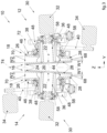
- numeral 10 indicates a stretching unit for stretching continuous elastic films in a direction transversal to their longitudinal directions.
- the stretching unit 10 comprises a first stretching device 12 and a second stretching device 14.
- the first and second stretching devices 12, 14 are substantially identical to each other.
- Each of the first and second stretching devices 12, 14 comprises first and second stretching members 16, 18 rotating about respective first and second axes of rotation 20, 22 ( figure 3 ) inclined with respect to each other.
- the first and second stretching members 16, 18 may be disk-shaped, as shown in the drawings. In possible embodiments, the first and second stretching members 16, 18 may have a shape different from that of a disk.
- the first and second stretching members 16, 18 have respective outer edges 24, 26 provided with gripping elements for gripping corresponding side edges of an elastic film.
- the gripping elements may be suction holes 28 open on the outer edges 24, 26 and connected to a sub-atmospheric pressure source, as it will be disclosed in the following.
- the outer edges 24, 26 of the stretching members 16, 18 may be provided with protruding pins that engage the side edges of an elastic film, alternatively or in addition to the suction holes 28.
- each of the first and second stretching devices 12, 14 comprises a respective driving assembly 30 configured for driving the respective first and second stretching members 16, 18 in rotation about the respective axes of rotation 20, 22.
- the driving assembly 30 of each of the first and second stretching devices 12, 14 is arranged on only one side with respect to the respective stretching members 16, 18. More specifically, the first and second stretching members 16, 18 of each of the first and second stretching devices 12, 14 are respectively distal and proximal with respect to the respective driving assembly 30, and the driving assembly 30 extends on only one side with respect to the first stretching member 16.
- the driving assembly 34 of each of the first and second stretching devices 12, 14 comprises first and second motors 32, 34 which drive respectively the first and second stretching members 16, 18.
- Each motor 32, 34 may comprise a respective reduction gear.
- both motors 32, 34 are arranged on only one side with respect to the respective stretching members 16, 18.
- the driving assembly 30 of each of the first and second stretching devices 12, 14 may comprise a single motor and a joint assembly which connects the single motor to the respective first and second stretching members 16, 18.
- the single motor and the joint assembly are arranged on only one side with respect to the respective stretching members 16, 18.
- the first motor 32 may be coaxial to the respective first stretching member 16 and may be connected thereto via a first shaft 36.
- the second motor 34 may be eccentric to the respective second stretching member 18 and may be connected thereto by a second shaft 38 and by a belt transmission including a toothed belt 40 and a pair of toothed pulleys.
- the suction holes 28 of each of the first and second stretching members 16, 18 communicate with a plurality of connection holes 42 open on side surfaces of the respective first and second stretching members 16, 18 facing the driving assembly 30.
- the connection holes 42 of each of the first and second stretching members 16, 18 are pneumatically connected to respective stationary suction chambers 44, 46 with open sides facing frontally the side surfaces of the respective first and second stretching members 16, 18 on which the connection holes 42 are open.
- the suction chambers 44, 46 are connected to a sub-atmospheric pressure source via respective tubular elements 48, 50 and flexible tubes (not shown).
- the suction chambers 44, 46 of each of the first and second stretching devices 12, 14 are arranged on the sides of the respective stretching members 16, 18 facing the respective driving assembly 30.
- the stationary suction chambers 44, 46 of each of the first and second stretching devices 12, 14 are coaxial to the respective first and second stretching members 16, 18.
- the suction chambers 44 of the first and second stretching devices 16, 18 connected to stretching members 16 which are distal with respect to the respective driving assembly 30 are selectively connectable and disconnectable from a sub-atmospheric pressure source, so that the stretching unit 10 may operate with only the outer stretching members 18 while the inner stretching members 16 are inoperative.
- each of the of the first and second stretching devices 12, 14 comprises first and second adjustment mechanisms 52, 54 associated respectively to the first and second stretching members 16, 18.
- Each of the of the first and second adjustment mechanisms 52, 54 is configured for adjusting the angle of inclination of the axis of rotation 20, 22 of the respective first and second stretching members 16, 18.
- the first and second adjustment mechanisms 52, 54 of each of the first and second stretching devices 12, 14 are arranged on the side of the respective first and second stretching members 16, 18 facing the respective driving assembly 30.
- each of the first and second adjustment mechanisms 52, 54 comprises a base 56 and an adjustable support structure 58.
- the angular position of the adjustable support structure 58 with respect to the base 56 can be adjusted about a respective adjustment axis 60.
- the angular movement of the adjustable support structure 58 about the adjustment axis 60 may be controlled by a manually actuated lever 62 or by a motor (not shown).
- Each adjustable support structure 58 rotatably supports a respective first shaft 36 or second shaft 38. Therefore, an angular adjustment of the adjustable support structure 58 about the adjustment axis 60 changes the inclination of the respective first axis of rotation 20 or second axis of rotation 22.
- the stationary suction chambers 44, 46 of each of the first and second stretching devices 12, 14 are supported by the adjustable support structure 58 of a respective first and second adjustment mechanism 52, 54. Therefore, when the inclination of the axes of rotation 20, 22 of the first and second stretching members 16, 18 is adjusted, the relative position between the first and second stretching members 16, 18 and the respective stationary suction chambers 44, 46 does not change.
- each of the first and second adjustment mechanisms 52, 54 may comprise respective guides 64 which allow adjustment of the position of the respective first and second adjustment mechanisms 52, 54 along a transverse direction Y.
- Each of the first and second adjustment mechanisms 52, 54 may comprise an auxiliary adjustment device 66 which allow adjustment of the position of the respective first and second stretching members 16, 18 along a linear direction X and/or Z orthogonal to the transverse direction Y.
- the auxiliary adjustment devices 66 may be controlled manually or by respective motors (not shown).
- each of the first and second stretching devices 12, 14 has a respective gripping zone 68 and a respective release zone 70.
- the first and second stretching members 16, 18 of each of the first and second stretching devices 12, 14 are spaced from each other in the transverse direction Y by first distance W1 in the gripping zones 68 and by a second distance W2 greater than the first distance W1 in the release zones 70.
- the distances W1, W2 of the first and second stretching device 12, 14 may be equal to or different from each other.
- the release zones 70 of the first and second stretching devices 12, 14 are aligned to each other along a common transverse release line 72.
- first and second stretching devices 12, 14 are set on opposite sides with respect to a central plane 74 orthogonal to the common transverse release line 74.
- the two first stretching members 16 of the first and second stretching devices 12, 14 which are distal with respect to the respective driving assemblies 30 face opposite sides of the central plane 74.
- each of the first and second stretching devices 12, 14 the respective driving assembly 30, stationary suction chambers 44, 46 and adjustment mechanisms 52, 54 extend on only one side of the central plane 74.
- the driving assembly 30, stationary suction chambers 44, 46 and adjustment mechanisms 52, 54 of the first and second stretching device 12, 14 extend on opposite sides of the central plane 74.
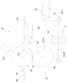
- an apparatus for producing elastic laminates is indicated by the reference numeral 76.
- the apparatus 76 comprises a first feeding device 78 configured to feed a single continuous elastic film 80 in a direction X parallel to its longitudinal axis.
- the apparatus 10 comprises a stretching unit 10 as previously disclosed, including first and second stretching devices 12, 14.
- the single continuous elastic film 80 is cut longitudinally in a longitudinal cutting unit 82 so as to form first and second continuous elastic films 84, 86 which are fed to the stretching unit 10 by a second feeding device 88.
- the apparatus 10 comprises an anvil wheel 90 rotatable about a transverse axis of rotation.
- the anvil wheel 90 has an outer cylindrical surface provided with suction holes pneumatically connected to a source of sub-atmospheric pressure 91 ( figure 5 ).
- the outer cylindrical surface of the anvil wheel 90 is tangent to the common transverse release line 72 of the stretching unit 10.
- the apparatus 10 comprises a third feeding device 92 and a fourth feeding device 94 configured to feed to the anvil wheel 90 first and second nonwoven webs 96, 98, respectively.
- each of the third feeding device and fourth feeding devices 94 may feed to the anvil wheel 90 two parallel first nonwoven webs 96 and two parallel second nonwoven webs 98.
- the first nonwoven web 96 or the two parallel first nonwoven webs 96 is/are applied to the anvil wheel 50 upstream of the common transverse release line 72 of the stretching unit 10, and the second nonwoven web 98 or the two parallel second nonwoven webs 98 is/are applied to the anvil wheel 90 downstream of the common transverse release line 72, with reference to the direction of rotation of the anvil wheel 90 indicated by the arrow 100 in Figure 4 .
- the apparatus 76 comprises a fastening device 102 cooperating with the outer cylindrical surface of the anvil wheel 90.
- the fastening device 102 may be an ultrasonic welding device, a pressure device for fastening by adhesive, or a thermal or thermomechanical welding device.
- the single continuous elastic film 80 is unwound from a reel and is cut longitudinally to form first and second continuous elastic films 84, 86.
- the first and second continuous elastic films 84, 86 may have respective width W1 equal to or different from each other.
- the first and second continuous elastic films 84, 86 may be unwound from respective reels.
- the first and second continuous elastic films 84, 86 may be equal or different from each other, e.g. they may be made of materials with different elastic properties.
- the lateral edges of the first and second continuous elastic films 84, 86 are gripped the outer edges 24, 26 of the respective first and second stretching devices 12, 14 of the stretching unit 10.
- the first and second stretching devices 12, 14 pickup the first and second continuous elastic films 84, 86 in the respective gripping zones 68 with respective first width W1 and rotate about the respective axes of rotation 20, 22.
- the two continuous elastic films 84, 86 are stretched in a transverse direction Y in the path from the respective gripping zones 68 to the respective release zones 70.
- the two continuous elastic films 84, 86 have respective width W2, which may be equal to or different from each other.
- the first nonwoven web 96 or the two parallel first nonwoven webs 96 is/are applied to the outer cylindrical surface of the anvil wheel 90 at or upstream of the common transverse release line 72.
- the first and second continuous elastic films 84, 86 while held stretched in the transverse direction Y, are detached from the outer edges 24, 26 of the respective first and second stretching members 14, 16 and are applied onto the first nonwoven web 96 or on respective parallel first nonwoven webs 96 held on the outer cylindrical surface of the anvil wheel 90 in the respective release zones 70, 76, aligned along the common transverse release line 72.
- the first and second continuous elastic films 84 86 are kept in a transversely stretched state on the outer cylindrical surface of the anvil wheel 90, e.g. by suction.
- first and second continuous elastic films 84, 86 on the first nonwoven web 96 or on respective parallel first nonwoven webs 96 along the common transverse release line 72 ensures a high accuracy of mutual positioning between the two continuous elastic films 84, 86 and the first nonwoven web(s) 96.
- the second nonwoven web 98 or two parallel second nonwoven webs 98 is/are applied on the anvil wheel 90 above the two parallel continuous elastic films 84, 86 so that the elastic films 84, 86, elastically stretched in the transverse direction Y, are sandwiched between the first and the second nonwoven webs 96, 98 or between two pairs of first and the second nonwoven webs 96, 98.
- the nonwoven webs 96, 98 are joined together, for example by ultrasonic welding, through the two parallel continuous first and second elastic films 84, 86 by the fastening device 102, thereby forming a continuous elastic laminate 104 or two parallel continuous elastic laminates 104.
- Joining to each other the nonwoven webs 96, 98 through the two parallel continuous elastic films 84, 86 includes both the direct fastening of the nonwoven webs 96, 98 through openings in the elastic films 84, 86, and fastening of the nonwoven webs 96, 98 on opposite sides of the elastic films 84, 86.
- the fastening device 102 may be configured to form a plurality of connecting points that form respective holes passing through the elastic films 84 86, and that directly fix the opposite nonwoven webs 94, 96 to each other through the holes formed in the elastic films 84, 86.
- the elastic films 84, 86 remain anchored to the nonwoven webs 96, 98 at the connecting points that extend through the holes formed in the elastic films 84, 86. This provides breathable elastic laminates thanks to the formation of holes passing through the elastic films 84 86.
- Figure 6 shows a second embodiment of an apparatus 76 for producing elastic laminates.
- the elements corresponding to those previously disclosed are indicated by the same reference numerals.
- the apparatus 76 comprises a transfer wheel 106 arranged between the stretching unit 10 and the anvil wheel 90.
- the transfer wheel 106 rotates about an axis of rotation parallel to the axis of rotation of the anvil wheel 90 and has an outer cylindrical surface which is tangent to the outer cylindrical surface of the anvil wheel 90 along a transverse line.
- the transfer wheel 106 is provided with gripping elements configured to hold the transversally stretched first and second continuous elastic films 84, 86.
- the gripping elements may consist of suction holes open on the outer cylindrical surface of the transfer wheel 106 and pneumatically connected to a source of sub-atmospheric pressure, for retaining by suction the transversally stretched first and second continuous elastic films 84, 86.
- the gripping elements may comprise projecting pins, in addition or in alternative to suction holes.
- the stretching unit 10 applies the transversally stretched first and second continuous elastic films 84, 86 on the outer cylindrical surface of the transfer wheel 106 in the release zones 70 aligned along the common transverse release line 72.
- the first and second continuous elastic films 84, 86 stretched in the transversal direction Y are detached from the first and second stretching members 16, 18 of the stretching unit 10 and are taken, e.g. by suction, on the outer cylindrical surface of the transfer wheel 106.
- the first and second continuous elastic films 84, 86 stretched in the transversal direction Y are then detached from the transfer wheel 106 and are applied on the first nonwoven web 96 or on the two parallel first nonwoven webs 96 held on the outer cylindrical surface of the anvil wheel 90.
- the first nonwoven web 96 or the two parallel first nonwoven webs 96 may be applied to the outer cylindrical surface of the anvil wheel 90 by first being applied to the transfer wheel 106, above the transversally stretched elastic films 84, 86.
- the two parallel continuous elastic films 84, 86 (which are made of nonporous material) are applied directly in contact with the outer cylindrical surface of the transfer wheel 40 without the interposition of a layer of porous material. This allows retaining the continuous elastic films 84, 86 in a transversally stretched condition with high accuracy. Also, the two parallel continuous elastic films 84, 86 are transferred from the transfer wheel 106 to the anvil wheel 90 between two tangent cylindrical surfaces, which simplifies the transfer of the elastic films and avoids positioning errors that may occur when the elastic films are applied on nonwoven webs starting from surfaces with inclined axes.
- the apparatus 76 may comprise at least one longitudinal cutting device 108 configured to cut along at least one longitudinal cutting line the transversally stretched continuous elastic film 84, 86 held on the outer cylindrical surface of the transfer wheel 106.
- the stretching unit 10 may apply to the transfer wheel 106 a single continuous elastic film 80, which is cut longitudinally on the transfer wheel 106.
- the single continuous elastic film 80 may be cut longitudinally along a plurality of parallel cutting lines so as to form more than two parallel continuous elastic films.
- the longitudinal cutting device 108 may comprise a cutting disk 109 rotating about an axis parallel to the axis of rotation of the transfer wheel 106.
- the cutting disk 109 may cooperate with a respective circumferential slot formed on the outer cylindrical surface of the transfer wheel 106.
- the apparatus may comprise a longitudinal cutting device arranged for carrying out the longitudinal cut of one or more continuous elastic films on the anvil wheel 90.
- the longitudinal cutting device may cut the elastic films without cutting the underneath nonwoven webs.
- the apparatus according to the present invention has a great flexibility regarding the possibility to produce different types of elastic laminates.
- a first embodiment of an elastic laminate 110 comprises first and second continuous elastic films 84, 86 sandwiched between first and second wide nonwoven webs 96, 98 and fixed to the two nonwoven webs 96, 98 by a pattern of connecting points 112.
- the elastic laminate 110 may have a non-elastic portion 114 in which the elastic films 84 86 are transversely spaced apart from each other and the two nonwoven webs 96, 98 are directly in contact with each other.
- the two wide nonwoven webs 96, 98 are directly fixed to each other in the non-elastic portion 114 comprised between the two parallel continuous elastic films 84, 86, and along the longitudinal edges external to elastic films 84, 86.
- the fastening device 102 may be configured to carry out a uniform fastening pattern over the entire surface of the nonwoven webs 96, 98, both at the elastic films 84, 86 and in the non-elastic portion 114.
- the apparatus according to the present invention may comprise a cutting unit configured for forming a longitudinal weakening line on the non-elastic portion 114, which forms a preferential breaking line which allows the two elastic parts of the elastic laminate 104 to be detached from each other following the application of a weak detaching force.
- the apparatus according to the present invention may produce two separate continuous elastic laminates 110, each comprising one continuous elastic film 84, 86 sandwiched between respective first and second narrow nonwoven webs 96, 98.
- the two continuous elastic laminates 110 of figure 8 may be produced by feeding on the anvil wheel two separate first narrow nonwoven webs 96 and two separate second narrow nonwoven webs 98 which are overlapped to respective first and second continuous elastic films 84, 86.
- first and second continuous elastic films 84, 86 may have the same or different widths, they may be transversally stretched by equal or different stretching rates W2/W1, and they may be made of the same or of different materials.
- the apparatus according to the present invention may also produce an elastic laminate 110 having a single wide continuous elastic film 80 sandwiched between first and second wide nonwoven webs 96, 98.
- the elastic laminate 110 of figure 9 may be produced by transversally stretching the single continuous elastic film 80 by the two second stretching members 18 of the stretching unit 10.
- the two first stretching members 16 of the stretching unit 10 may be disconnected from the sub-atmospheric pressure source and moved in the direction X away from the common transverse release line 72, so that they do not interfere with the single continuous elastic film 80.
- the apparatus according to the present invention may also produce an elastic laminate 110 having only one continuous elastic film 84 sandwiched between first and second wide nonwoven webs 96, 98 which form a wide non-elastic portion 116 extending laterally to the continuous elastic film 84.
- the elastic laminate 110 of figure 10 may be produced by transversally stretching only one continuous elastic film 84 by the two stretching members 16, 18 of only one stretching device 12 of the stretching unit 10.
- the non-elastic portion 116 may extend on the left or on the right of the continuous elastic film 84.
- the single continuous elastic film 84 may be enclosed centrally between two wide nonwoven webs 96, 98 which form wide non-elastic portions 116 extending laterally from opposite sides of the single continuous elastic film 84. In a possible embodiment a single continuous elastic film 84 may be enclosed laterally between a wide nonwoven web and a narrow nonwoven web.
- a wide nonwoven web 96, 98 has a width greater than the width of the first and second continuous elastic films 84, 86 set side by side, and a narrow nonwoven web 96, 98 has a width lower than the width of a wide nonwoven web 96, 98 and greater than the width of one continuous elastic films 84, 86.
- the apparatus may comprise one or two winding units configured for winding one or two elastic laminates 110 in one or two reels.
Claims (15)
- Dispositif d'étirement (12, 14) destiné à étirer transversalement des films élastiques (84, 86), comprenant :des premier et second éléments d'étirement (16, 18) ayant des bords extérieurs (24, 26) respectifs pourvus d'éléments de préhension (28) conçus pour saisir des bords correspondants d'un film élastique (84 86), lesdits premier et second éléments d'étirement (16, 18) ayant des premier et second axes de rotation (20, 22) respectifs inclinés l'un par rapport à l'autre, etun ensemble d'entraînement (30) conçu pour entraîner lesdits premier et second éléments d'étirement (16, 18) en rotation autour des axes de rotation (20, 22) respectifs, les premier et second éléments d'étirement (16, 18) étant respectivement distaux et proximaux par rapport audit ensemble d'entraînement (30) et caractérisé en ce que l'ensemble d'entraînement (30) s'étend d'un seul côté par rapport audit premier élément d'étirement (16) .
- Dispositif d'étirement selon la revendication 1, ledit ensemble d'entraînement (30) comprenant des premier et second moteurs (32, 34) connectés aux premier et second éléments d'étirement (16, 18) respectifs, et lesdits premier et second moteurs (32, 34) étant disposés du même côté par rapport aux premier et second éléments d'étirement (16, 18) respectifs.
- Dispositif d'étirement selon la revendication 2, ledit premier moteur (32) étant relié au premier élément d'étirement (16) par un premier arbre (36) coaxial audit premier axe de rotation (20) et ledit second moteur (34) étant excentré par rapport audit second axe de rotation (22) et étant relié au second élément d'étirement (18) par une transmission par courroie (40).
- Dispositif d'étirement selon l'une quelconque des revendications précédentes, le bord extérieur (24, 26) de chacun desdits premier et second éléments d'étirement (16, 18) comprenant une pluralité de trous d'aspiration (28) reliés pneumatiquement à une chambre d'aspiration fixe (44, 46) respective, et lesdites chambres d'aspiration fixes (44, 46) étant disposées du même côté par rapport aux premier et second éléments d'étirement (16, 18) respectifs.
- Dispositif d'étirement selon la revendication 4, lesdites chambres d'aspiration fixes (44, 46) étant coaxiales aux premier et second éléments d'étirement (16, 18) respectifs.
- Dispositif d'étirement selon la revendication 4 ou la revendication 5, les trous d'aspiration (28) de chacun desdits premier et second éléments d'étirement (16, 18) étant reliés à des trous de liaison (42) ouverts sur une surface latérale des premier et second éléments d'étirement (16, 18) respectifs orientés vers ledit ensemble d'entraînement (30) et chacune desdites chambres d'aspiration (44, 46) étant ouverte frontalement sur ladite surface latérale des premier et second éléments d'étirement (16, 18) respectifs.
- Dispositif d'étirement selon l'une quelconque des revendications précédentes, comprenant des premier et second mécanismes de réglage (52, 54) conçus pour régler l'angle d'inclinaison de l'axe de rotation (20, 22) des premier et second éléments d'étirement (16, 18) respectifs.
- Dispositif d'étirement selon la revendication 7, chacun desdits premier et second mécanismes de réglage (52, 54) comprenant une structure de support réglable (58) portant un premier ou second élément d'étirement (16, 18) respectif, un premier ou second moteur (32, 34) respectif, et une première ou seconde chambre d'aspiration fixe (44, 46) respective.
- Dispositif d'étirement selon la revendication 8, la structure de support réglable (58) de chacun desdits premier et second mécanismes de réglage (52, 54) étant réglable en rotation par rapport à une base (56) respective autour d'un axe de réglage (60) respectif.
- Dispositif d'étirement selon la revendication 9, la base (56) de chacun desdits premier et second mécanismes de réglage (52, 54) étant réglable en translation le long d'une direction transversale (Y).
- Dispositif d'étirement selon l'une quelconque des revendications 7 à 10, chacun desdits premier et second mécanismes de réglage (52, 54) comprenant un dispositif de réglage auxiliaire (66) conçu pour régler la position des premier et second éléments d'étirement (16, 18) respectifs le long d'une direction linéaire (X, Z).
- Dispositif d'étirement selon l'une quelconque des revendications précédentes, chacun desdits éléments d'étirement (16, 18) ayant une forme de disque.
- Dispositif d'étirement selon l'une quelconque des revendications précédentes, ledit premier élément d'étirement (16) ayant un plan médian orthogonal à l'axe de rotation (20) respectif, et ledit ensemble d'entraînement (30) s'étendant d'un seul côté dudit plan médian.
- Unité d'étirement (10) destinée à étirer transversalement des films élastiques (84, 86), comprenant des premier et second dispositifs d'étirement (12, 14) selon l'une quelconque des revendications précédentes, lesdits premier et second dispositifs d'étirement (12, 14) ayant des zones de préhension (68) respectives et des zones de libération (70) respectives, et les zones de libération (70) des premier et second dispositifs d'étirement (12, 14) étant alignées l'une par rapport à l'autre le long d'une ligne de libération transversale commune (72).
- Unité d'étirement (10) destinée à étirer transversalement des films élastiques (84, 86), comprenant des premier et second dispositifs d'étirement (12, 14) selon l'une quelconque des revendications précédentes, lesdits premier et second dispositifs d'étirement (12, 14) ayant des zones de préhension (68) respectives et des zones de libération (70) respectives, et les zones de libération (70) des premier et second dispositifs d'étirement (12, 14) étant décalées transversalement et angulairement l'une de l'autre.
Priority Applications (4)
| Application Number | Priority Date | Filing Date | Title |
|---|---|---|---|
| EP21189770.7A EP4129628B1 (fr) | 2021-08-05 | 2021-08-05 | Dispositif et unité d'étirement transversal de films élastiques |
| PL21189770.7T PL4129628T3 (pl) | 2021-08-05 | 2021-08-05 | Urządzenie i jednostka do poprzecznego rozciągania folii elastycznych |
| CN202210917960.9A CN115891123A (zh) | 2021-08-05 | 2022-08-01 | 用于横向拉伸弹性薄膜的装置和单元 |
| US17/879,094 US20230039478A1 (en) | 2021-08-05 | 2022-08-02 | A device and unit for transversely stretching elastic films |
Applications Claiming Priority (1)
| Application Number | Priority Date | Filing Date | Title |
|---|---|---|---|
| EP21189770.7A EP4129628B1 (fr) | 2021-08-05 | 2021-08-05 | Dispositif et unité d'étirement transversal de films élastiques |
Publications (2)
| Publication Number | Publication Date |
|---|---|
| EP4129628A1 EP4129628A1 (fr) | 2023-02-08 |
| EP4129628B1 true EP4129628B1 (fr) | 2023-11-08 |
Family
ID=77226645
Family Applications (1)
| Application Number | Title | Priority Date | Filing Date |
|---|---|---|---|
| EP21189770.7A Active EP4129628B1 (fr) | 2021-08-05 | 2021-08-05 | Dispositif et unité d'étirement transversal de films élastiques |
Country Status (4)
| Country | Link |
|---|---|
| US (1) | US20230039478A1 (fr) |
| EP (1) | EP4129628B1 (fr) |
| CN (1) | CN115891123A (fr) |
| PL (1) | PL4129628T3 (fr) |
Families Citing this family (1)
| Publication number | Priority date | Publication date | Assignee | Title |
|---|---|---|---|---|
| CN116100794B (zh) * | 2023-04-04 | 2023-06-06 | 青州富翔塑业有限公司 | 双向拉伸聚酯薄膜成型装置 |
Family Cites Families (3)
| Publication number | Priority date | Publication date | Assignee | Title |
|---|---|---|---|---|
| EP2260813B1 (fr) * | 2009-05-29 | 2015-07-15 | Fameccanica.Data S.p.A. | Dispositif et procédé pour la formation de bandes tensionnées rendues elastiques, pour example pour articles hygieniques et program d'ordinateur pour en tel produit |
| US9005501B2 (en) * | 2011-08-17 | 2015-04-14 | Reifenhaeuser Gmbh & Co. Kg Maschinenfabrik | Method and apparatus for producing a film web from thermoplastic material and film produced thereby |
| CN113633467B (zh) | 2016-08-12 | 2022-10-11 | 宝洁公司 | 用于装配吸收制品的方法和设备 |
-
2021
- 2021-08-05 EP EP21189770.7A patent/EP4129628B1/fr active Active
- 2021-08-05 PL PL21189770.7T patent/PL4129628T3/pl unknown
-
2022
- 2022-08-01 CN CN202210917960.9A patent/CN115891123A/zh active Pending
- 2022-08-02 US US17/879,094 patent/US20230039478A1/en active Pending
Also Published As
| Publication number | Publication date |
|---|---|
| US20230039478A1 (en) | 2023-02-09 |
| PL4129628T3 (pl) | 2024-03-11 |
| CN115891123A (zh) | 2023-04-04 |
| EP4129628A1 (fr) | 2023-02-08 |
Similar Documents
| Publication | Publication Date | Title |
|---|---|---|
| EP3028687B1 (fr) | Appareil et procédé de production d'une bande élastique composite à sections élastiques intermittentes | |
| EP1609582B1 (fr) | Dispositif d'etancheite et procede d'etancheification faisant appel a ce dernier | |
| EP3095589B1 (fr) | Dispositif de formation de soudures par ultrasons sur des matériaux en bande en mouvement continu | |
| EP3415131B1 (fr) | Appareil et procédé de production d'une bande élastique composite à sections élastiques intermittentes | |
| US20230039478A1 (en) | A device and unit for transversely stretching elastic films | |
| EP3932670B1 (fr) | Procédé et appareil de production de stratifiés élastiques | |
| WO2000073031A1 (fr) | Procede et dispositif permettant de produire des nappes de materiau sur lesquelles sont montes des morceaux de materiau | |
| WO2017212519A1 (fr) | Procédé de production et dispositif de production de composite en feuille continu pour article absorbant | |
| EP4129625B1 (fr) | Unité pour l'étirage transversal de films élastiques | |
| US10653565B2 (en) | Methods and apparatuses for separating discrete articles from continuous webs | |
| EP4129645A1 (fr) | Procédé et appareil de production de stratifiés élastiques | |
| JP2018514316A (ja) | 吸収性衛生用品を形成するユニット及び吸収性衛生用品を製造する方法 | |
| WO2014097636A1 (fr) | Procédé de production de couches jetables et dispositif de production | |
| WO2014103840A1 (fr) | Dispositif de production de feuille extensible et procédé de production | |
| EP4104805B1 (fr) | Procédé et appareil de production de stratifiés élastiques | |
| JP6681515B2 (ja) | 第一のウェブを非線形パターンでベースウェブに貼るための装置および方法 | |
| US11772332B2 (en) | Web welding system and welding method |
Legal Events
| Date | Code | Title | Description |
|---|---|---|---|
| PUAI | Public reference made under article 153(3) epc to a published international application that has entered the european phase |
Free format text: ORIGINAL CODE: 0009012 |
|
| STAA | Information on the status of an ep patent application or granted ep patent |
Free format text: STATUS: THE APPLICATION HAS BEEN PUBLISHED |
|
| AK | Designated contracting states |
Kind code of ref document: A1 Designated state(s): AL AT BE BG CH CY CZ DE DK EE ES FI FR GB GR HR HU IE IS IT LI LT LU LV MC MK MT NL NO PL PT RO RS SE SI SK SM TR |
|
| STAA | Information on the status of an ep patent application or granted ep patent |
Free format text: STATUS: REQUEST FOR EXAMINATION WAS MADE |
|
| 17P | Request for examination filed |
Effective date: 20230320 |
|
| RBV | Designated contracting states (corrected) |
Designated state(s): AL AT BE BG CH CY CZ DE DK EE ES FI FR GB GR HR HU IE IS IT LI LT LU LV MC MK MT NL NO PL PT RO RS SE SI SK SM TR |
|
| GRAP | Despatch of communication of intention to grant a patent |
Free format text: ORIGINAL CODE: EPIDOSNIGR1 |
|
| STAA | Information on the status of an ep patent application or granted ep patent |
Free format text: STATUS: GRANT OF PATENT IS INTENDED |
|
| INTG | Intention to grant announced |
Effective date: 20230623 |
|
| GRAS | Grant fee paid |
Free format text: ORIGINAL CODE: EPIDOSNIGR3 |
|
| GRAA | (expected) grant |
Free format text: ORIGINAL CODE: 0009210 |
|
| STAA | Information on the status of an ep patent application or granted ep patent |
Free format text: STATUS: THE PATENT HAS BEEN GRANTED |
|
| AK | Designated contracting states |
Kind code of ref document: B1 Designated state(s): AL AT BE BG CH CY CZ DE DK EE ES FI FR GB GR HR HU IE IS IT LI LT LU LV MC MK MT NL NO PL PT RO RS SE SI SK SM TR |
|
| REG | Reference to a national code |
Ref country code: GB Ref legal event code: FG4D |
|
| REG | Reference to a national code |
Ref country code: CH Ref legal event code: EP |
|
| REG | Reference to a national code |
Ref country code: DE Ref legal event code: R096 Ref document number: 602021006592 Country of ref document: DE |
|
| REG | Reference to a national code |
Ref country code: IE Ref legal event code: FG4D |
|
| REG | Reference to a national code |
Ref country code: SE Ref legal event code: TRGR |
|
| REG | Reference to a national code |
Ref country code: NL Ref legal event code: FP |
|
| REG | Reference to a national code |
Ref country code: LT Ref legal event code: MG9D |
|
| PG25 | Lapsed in a contracting state [announced via postgrant information from national office to epo] |
Ref country code: GR Free format text: LAPSE BECAUSE OF FAILURE TO SUBMIT A TRANSLATION OF THE DESCRIPTION OR TO PAY THE FEE WITHIN THE PRESCRIBED TIME-LIMIT Effective date: 20240209 |
|
| PG25 | Lapsed in a contracting state [announced via postgrant information from national office to epo] |
Ref country code: IS Free format text: LAPSE BECAUSE OF FAILURE TO SUBMIT A TRANSLATION OF THE DESCRIPTION OR TO PAY THE FEE WITHIN THE PRESCRIBED TIME-LIMIT Effective date: 20240308 |
|
| PG25 | Lapsed in a contracting state [announced via postgrant information from national office to epo] |
Ref country code: LT Free format text: LAPSE BECAUSE OF FAILURE TO SUBMIT A TRANSLATION OF THE DESCRIPTION OR TO PAY THE FEE WITHIN THE PRESCRIBED TIME-LIMIT Effective date: 20231108 |
|
| PG25 | Lapsed in a contracting state [announced via postgrant information from national office to epo] |
Ref country code: LT Free format text: LAPSE BECAUSE OF FAILURE TO SUBMIT A TRANSLATION OF THE DESCRIPTION OR TO PAY THE FEE WITHIN THE PRESCRIBED TIME-LIMIT Effective date: 20231108 Ref country code: IS Free format text: LAPSE BECAUSE OF FAILURE TO SUBMIT A TRANSLATION OF THE DESCRIPTION OR TO PAY THE FEE WITHIN THE PRESCRIBED TIME-LIMIT Effective date: 20240308 Ref country code: GR Free format text: LAPSE BECAUSE OF FAILURE TO SUBMIT A TRANSLATION OF THE DESCRIPTION OR TO PAY THE FEE WITHIN THE PRESCRIBED TIME-LIMIT Effective date: 20240209 Ref country code: BG Free format text: LAPSE BECAUSE OF FAILURE TO SUBMIT A TRANSLATION OF THE DESCRIPTION OR TO PAY THE FEE WITHIN THE PRESCRIBED TIME-LIMIT Effective date: 20240208 Ref country code: PT Free format text: LAPSE BECAUSE OF FAILURE TO SUBMIT A TRANSLATION OF THE DESCRIPTION OR TO PAY THE FEE WITHIN THE PRESCRIBED TIME-LIMIT Effective date: 20240308 |