EP4129624A1 - Pouch bending guide apparatus and pouch bending method for secondary battery packaging system - Google Patents
Pouch bending guide apparatus and pouch bending method for secondary battery packaging system Download PDFInfo
- Publication number
- EP4129624A1 EP4129624A1 EP20929169.9A EP20929169A EP4129624A1 EP 4129624 A1 EP4129624 A1 EP 4129624A1 EP 20929169 A EP20929169 A EP 20929169A EP 4129624 A1 EP4129624 A1 EP 4129624A1
- Authority
- EP
- European Patent Office
- Prior art keywords
- bending
- pouch
- jig
- sheet
- folded
- Prior art date
- Legal status (The legal status is an assumption and is not a legal conclusion. Google has not performed a legal analysis and makes no representation as to the accuracy of the status listed.)
- Granted
Links
Images


Classifications
-
- B—PERFORMING OPERATIONS; TRANSPORTING
- B29—WORKING OF PLASTICS; WORKING OF SUBSTANCES IN A PLASTIC STATE IN GENERAL
- B29C—SHAPING OR JOINING OF PLASTICS; SHAPING OF MATERIAL IN A PLASTIC STATE, NOT OTHERWISE PROVIDED FOR; AFTER-TREATMENT OF THE SHAPED PRODUCTS, e.g. REPAIRING
- B29C53/00—Shaping by bending, folding, twisting, straightening or flattening; Apparatus therefor
- B29C53/80—Component parts, details or accessories; Auxiliary operations
-
- H—ELECTRICITY
- H01—ELECTRIC ELEMENTS
- H01M—PROCESSES OR MEANS, e.g. BATTERIES, FOR THE DIRECT CONVERSION OF CHEMICAL ENERGY INTO ELECTRICAL ENERGY
- H01M10/00—Secondary cells; Manufacture thereof
- H01M10/04—Construction or manufacture in general
- H01M10/0404—Machines for assembling batteries
-
- B—PERFORMING OPERATIONS; TRANSPORTING
- B29—WORKING OF PLASTICS; WORKING OF SUBSTANCES IN A PLASTIC STATE IN GENERAL
- B29C—SHAPING OR JOINING OF PLASTICS; SHAPING OF MATERIAL IN A PLASTIC STATE, NOT OTHERWISE PROVIDED FOR; AFTER-TREATMENT OF THE SHAPED PRODUCTS, e.g. REPAIRING
- B29C53/00—Shaping by bending, folding, twisting, straightening or flattening; Apparatus therefor
- B29C53/02—Bending or folding
- B29C53/04—Bending or folding of plates or sheets
-
- H—ELECTRICITY
- H01—ELECTRIC ELEMENTS
- H01M—PROCESSES OR MEANS, e.g. BATTERIES, FOR THE DIRECT CONVERSION OF CHEMICAL ENERGY INTO ELECTRICAL ENERGY
- H01M50/00—Constructional details or processes of manufacture of the non-active parts of electrochemical cells other than fuel cells, e.g. hybrid cells
- H01M50/10—Primary casings; Jackets or wrappings
- H01M50/102—Primary casings; Jackets or wrappings characterised by their shape or physical structure
- H01M50/105—Pouches or flexible bags
-
- B—PERFORMING OPERATIONS; TRANSPORTING
- B21—MECHANICAL METAL-WORKING WITHOUT ESSENTIALLY REMOVING MATERIAL; PUNCHING METAL
- B21D—WORKING OR PROCESSING OF SHEET METAL OR METAL TUBES, RODS OR PROFILES WITHOUT ESSENTIALLY REMOVING MATERIAL; PUNCHING METAL
- B21D11/00—Bending not restricted to forms of material mentioned in only one of groups B21D5/00, B21D7/00, B21D9/00; Bending not provided for in groups B21D5/00 - B21D9/00; Twisting
- B21D11/20—Bending sheet metal, not otherwise provided for
-
- Y—GENERAL TAGGING OF NEW TECHNOLOGICAL DEVELOPMENTS; GENERAL TAGGING OF CROSS-SECTIONAL TECHNOLOGIES SPANNING OVER SEVERAL SECTIONS OF THE IPC; TECHNICAL SUBJECTS COVERED BY FORMER USPC CROSS-REFERENCE ART COLLECTIONS [XRACs] AND DIGESTS
- Y02—TECHNOLOGIES OR APPLICATIONS FOR MITIGATION OR ADAPTATION AGAINST CLIMATE CHANGE
- Y02E—REDUCTION OF GREENHOUSE GAS [GHG] EMISSIONS, RELATED TO ENERGY GENERATION, TRANSMISSION OR DISTRIBUTION
- Y02E60/00—Enabling technologies; Technologies with a potential or indirect contribution to GHG emissions mitigation
- Y02E60/10—Energy storage using batteries
-
- Y—GENERAL TAGGING OF NEW TECHNOLOGICAL DEVELOPMENTS; GENERAL TAGGING OF CROSS-SECTIONAL TECHNOLOGIES SPANNING OVER SEVERAL SECTIONS OF THE IPC; TECHNICAL SUBJECTS COVERED BY FORMER USPC CROSS-REFERENCE ART COLLECTIONS [XRACs] AND DIGESTS
- Y02—TECHNOLOGIES OR APPLICATIONS FOR MITIGATION OR ADAPTATION AGAINST CLIMATE CHANGE
- Y02P—CLIMATE CHANGE MITIGATION TECHNOLOGIES IN THE PRODUCTION OR PROCESSING OF GOODS
- Y02P70/00—Climate change mitigation technologies in the production process for final industrial or consumer products
- Y02P70/50—Manufacturing or production processes characterised by the final manufactured product
Definitions
- the present disclosure relates generally to pouch bending guide apparatus and pouch bending method for a secondary battery packaging system. More particularly, the present disclosure relates to pouch bending guide apparatus and pouch bending method for a secondary battery packaging system in which during the folding of a pouch, a bending lateral surface of the pouch can be prevented from being deformed concavely.
- the present disclosure relates to the bending of a pouch for a secondary battery packaging system, and is intended to prevent a bending portion of the pouch from being moved to the inside of a main chamber by using a bending knife.
- the prevention of the bending portion of the pouch from being moved to the inside of the main chamber means to prevent a bending lateral surface on one side of the pouch from being pushed to the inside of the pouch when forming the pouch by folding a pouch sheet.
- a secondary battery can be recharged and can be small and large-capacity.
- the secondary battery may be a can-type secondary battery or pouch-type secondary battery according to the shape of an outer casing of the secondary battery, wherein the pouch-type secondary battery consists of a battery cell having an electrode tab formed on one side of an electrode plate, and a pouch that covers and seals the electrode plate so that the electrode tab is drawn out of the pouch.
- the battery cell has a separator interposed between a plurality of positive and negative electrode plates, and the battery cell is mounted and sealed inside the pouch, and the electrode tab on one side of the battery cell is drawn out of the pouch.
- a battery having a battery cell mounted in the pouch is referred to as a pouch-type secondary battery.
- the center part of a pouch sheet having half battery cell receiving parts is folded and the battery cell is mounted in the battery cell receiving part of the inside of the pouch.
- the center part of the pouch sheet is pushed inward, and a bending lateral surface of the pouch is deformed concavely inward. That is, when the pouch sheet is folded, the bending lateral surface of the pouch 2 is moved inward and is deformed concavely.
- a bending portion of the pouch In the case of a battery without a bottom, while a pouch is bent, a bending portion of the pouch is moved to the inside of a main chamber, and thus the size of the main chamber decreases.
- the movement of the bending portion of the pouch to the inside of the main chamber means that when forming the pouch by folding the pouch sheet, a bending lateral surface on one side of the pouch 2 is pushed to the inside of the pouch. Accordingly, during the bending of the pouch 2, the bending portion of the pouch is moved to the inside of the main chamber, and thus the size of the main chamber of the pouch decreases.
- a plurality of pouches (hereinafter, referred to as a pouch for convenience) in which battery cells are mounted is placed by standing side by side on a hanger frame, and the bending lateral surface of each of the pouches is in contact with a heat sink (which may be a metal plate having high thermal conductivity, for example, an aluminum plate) provided on the lower part of the hanger frame.
- a heat sink which may be a metal plate having high thermal conductivity, for example, an aluminum plate
- the concave deformation part When the pouch has a concave deformation part formed in such a manner that the bending lateral surface of the pouch is recessed inward, the concave deformation part is not efficiently in contact with the heat sink. Accordingly, heat generated in the pouch during the charging/discharging of the battery cell is not efficiently transmitted from the bending lateral surface to the heat sink, and thus heat generated in the pouch during the charging/discharging of the battery cell is not efficiently discharged, and when the heat discharge from the pouch is not efficiently performed, the battery cell deteriorates or catches fire due to heat.
- the present disclosure is intended to propose pouch bending guide apparatus and pouch bending method for a secondary battery packaging system having a new configuration in which a bending lateral surface of a pouch can be prevented from being deformed concavely in the bending process of folding a bending jig toward a base jig after a battery cell is placed on a pouch sheet, and heat generated during the charging/discharging of the battery cell of a secondary battery can be efficiently discharged from the pouch. That is, the present disclosure is mainly intended to prevent the bending lateral surface of the pouch from being recessed inward in the process of bending the pouch sheet to mount a battery cell in the pouch.
- a pouch bending guide apparatus for a secondary battery packaging system, which folds a pouch sheet while a bending jig is folded toward a base jig with the pouch sheet placed on the base jig and the bending jig, the apparatus including: a bending knife which supports, from an inside of a pouch, a bending lateral surface of the pouch formed while the pouch sheet is folded by the bending jig.
- the center part of the pouch sheet is prevented from being pushed inward, thereby preventing the bending lateral surface of the pouch from being deformed concavely inward.
- the bending lateral surface of the pouch is prevented from being pushed inward, thereby improving the exterior quality and reliability of the pouch.
- the present disclosure relates to a pouch bending guide apparatus for a secondary battery packaging system which folds a pouch sheet while the bending jig is folded toward the base jig with the pouch sheet placed on a base jig and a bending jig, the apparatus including a bending knife which supports, from the inside of a pouch, a bending lateral surface of the pouch formed while the pouch sheet is folded by the bending jig, wherein the bending knife is provided with a stopper, and while the pouch sheet is folded by the bending jig, the bending knife moves toward the inside of the pouch sheet such that a stopper supports the inner surface of the bending lateral surface of the pouch.
- the present disclosure relates to a pouch bending guide apparatus for a secondary battery packaging system which folds a pouch sheet 2A while the bending jig 20 is folded toward the base jig 30 with the pouch sheet 2A placed on a base jig 30 and a bending jig 20.
- the pouch bending guide apparatus of the present disclosure is provided with a bending knife 40 as a main part which supports, from the inside of a pouch, a bending lateral surface 2BS of the pouch 2 formed while the pouch sheet 2A is folded by the bending jig 20 such that the bending lateral surface 2BS of the pouch 2 is prevented from being pushed concavely inward, wherein the bending knife 40 is provided with a stopper 42 which supports the bending lateral surface 2BS from the inner surface of the pouch.
- the inner surface of the base jig 30 is disposed to be directed upward.
- the base jig 30 is formed to have the shape of a rectangular plate.
- the inner surface of the base jig 30 is provided with a pouch battery cell receiving part seating groove having the shape of a concave half groove.
- the pouch sheet 2A for forming the pouch 2 in which a battery cell is mounted includes two half battery cell receiving parts relative to the center of the pouch sheet 2A, and each of the half battery cell receiving parts of the pouch has the shape of a rectangular groove protruding outward from the pouch sheet 2A, and thus a half pouch battery cell receiving part seating groove of the base jig 30 is formed to have the shape of a rectangular groove such that the half battery cell receiving part is seated in the half pouch battery cell receiving part seating groove.
- the bending jig 20 is supported by a support frame and is folded toward or unfolded from the inner surface of the base jig 30 by a bending operation unit (not shown). Even the inner surface of the bending jig 20 is provided with a concave half pouch battery cell receiving part seating groove.
- the pouch battery cell receiving part seating groove of the bending jig 20 also has the shape of a rectangular groove.
- the base jig 30 is mounted to the support frame, and side walls of the base jig 30 and the bending jig 20 are coupled to each other by a hinge part.
- the inner surface of the base jig 30 and the bending jig 20 are disposed to face each other by folding the bending jig 20 toward the inner surface of the base jig 30, and the bending jig 20 is unfolded outward from the inner surface of the base jig 30.
- Each of the base jig 30 and the bending jig 20 is formed to have the shape of a plate having a pouch battery cell receiving part seating groove provided therein. The bending jig 20 is folded toward and unfolded from the base jig 30 relative to the hinge part.
- the inner surface of the bending jig 20 is disposed to be directed upward.
- a vacuum suction passage is formed inside each of the base jig 30 and the bending jig 20, and a plurality of vacuum suction holes communicating with the vacuum suction passage is formed in each of the inner surfaces of the base jig 30 and the bending jig 20 facing each other.
- the vacuum suction holes of the base jig 30 are connected with the vacuum suction passage of the inside of the base jig 30 and are open to the inner surface of the base jig 30.
- the vacuum suction holes of the bending jig 20 are also connected with the vacuum suction passage of the inside of the bending jig 20 and are open to the inner surface of the bending jig 20.
- the outer surface of the pouch sheet 2A placed on the inner surfaces of the base jig 30 and the bending jig 20 is disposed to face the vacuum suction holes of the base jig 30 and the vacuum suction holes of the bending jig 20.
- the vacuum suction passage of the inside of the base jig 30 and the vacuum suction holes thereof, and the vacuum suction passage of the inside of the bending jig 20 and the vacuum suction holes thereof are connected with a vacuum device, which is not shown, by a connecting hose, a vacuum connection block, and a vacuum pressure charging block. Air is suctioned through the vacuum suction holes of the inner surface of the base jig 30 and the vacuum suction holes of the inner surface of the bending jig 20 by the vacuum device such that the pouch sheet 2A can be in close contact with the inner surface of the base jig 30 and the inner surface of the bending jig 20 by vacuum.
- the vacuum device is connected with the vacuum suction passages of the base jig 30 and the bending jig 20 by a connection means such as a hose not shown, and while the pouch sheet 2A is suctioned on the base jig 30 and the bending jig 20 by the operation of the vacuum device, the bending jig 20 is folded toward or unfolded from the base jig 30 relative to the hinge part.
- a bending operation means may use a known device such as a cylinder, and thus a detailed description thereof will be omitted.
- the pouch sheet 2A is placed on the base jig 30 and the bending jig 20, and a battery cell is received in a half battery cell receiving part disposed on the base jig 30 among the pair of half battery cell receiving parts of the pouch sheet 2A, and while the two half battery cell receiving parts of the pouch sheet 2A are seated respectively in the pouch battery cell receiving part seating groove inside the base jig 30 and the pouch battery cell receiving part seating groove of the bending jig 20, the pouch sheet 2A is folded while the bending jig 20 is folded toward the base jig 30, and after the pouch sheet 2A is folded, the pouch 2 having the battery cell mounted in the half battery cell receiving part inside the pouch 2 is formed.
- the pouch 2 may be formed by folding the pouch sheet 2A in half relative to the center of the pouch sheet 2A, and one side surface of even a pouch 2 without battery cells is formed as a folding side surface.
- one side wall of the base jig 30 and one side wall of the bending jig 20 are connected to each other by the hinge part, and a bending guide opening part OP is formed on each of the side walls of the base jig 30 and the bending jig 20 such that the inner and outer surfaces of the side wall communicate with each other.
- the bending guide opening part OP is formed on each of the one side wall of the base jig 30 and the one side wall of the bending jig 20.
- the bending guide opening part OP is formed by passing through the side wall of each of the base jig 30 and the bending jig 20 from one side surface of the pouch battery cell receiving part seating groove formed inside each of the base jig 30 and the bending jig 20.
- the bending guide opening parts OP may be considered as guide holes to guide the bending lateral surface 2BS of the pouch 2 to be pushed to the outside when the stopper 42 to be described later pushes the inner surface of the bending lateral surface such that the bending lateral surface 2BS of the pouch 2 is prevented from being pushed to the inside of the pouch 2.
- the pouch bending guide apparatus of the present disclosure is provided with the bending knife 40 which supports the bending lateral surface 2BS of the pouch 2 from the inside thereof when the pouch sheet 2A is folded.
- the bending jig 20 When the base jig 3 and the bending jig 20 stop after moving along a movement path, the bending jig 20 is folded toward the base jig 30.
- the movement path is a track
- the bending jig 20 In a case in which the movement path is a turntable, when the base jig 30 and the bending jig 20 mounted to the turntable stop after moving according to the rotation of the turntable, the bending jig 20 is folded toward the base jig 30.
- a bending knife frame 50 is disposed at a side of the movement path. When the movement path is a turntable, the bending knife frame 50 is disposed next to the turntable.
- a lift drive motor 54 is mounted to the bending knife frame 50. The motor shaft of the lift drive motor 54 is arranged in a vertical direction. The motor shaft of the lift drive motor 54 is provided with a lifting ball screw.
- the bending knife frame 50 is provided with an LM guide.
- the LM guide is provided with a guide rail and a guide rail block, and the guide rail is arranged in a direction perpendicular to the bending knife frame 50.
- the guide rail block is coupled slidably to the guide rail.
- the guide rail is seen to include a pair of guide rails arranged respectively at left and right sides to be in parallel to each other.
- a bending knife support frame 60 is coupled to the bending knife frame 50.
- the bending knife support frame 60 is coupled to the bending knife frame 50 such that the bending knife support frame 60 is moved upward and downward by the LM guide.
- the bending knife frame 50 is coupled to the guide rail block of the LM guide, and the bending knife support frame 60 is coupled to the bending knife frame 50 to move upward and downward.
- the bending knife support frame 60 is provided with a lift ball screw nut.
- the lift ball screw nut is preferably provided on the center part of the lower surface of the bending knife support frame 60.
- the motor shaft of the lift drive motor 54 provided on the bending knife frame 50 is provided with the lifting ball screw, and the lifting ball screw nut provided in the bending knife support frame 60 is coupled to the lifting ball screw. Accordingly, as the motor shaft of the drive motor rotates, the bending knife support frame 60 may be raised and lowered on the bending knife frame 50 by the lifting ball screw and the lift ball screw nut.
- the bending knife support frame 60 is provided with an LM guide.
- An inclined frame 62 is provided on the upper part of the bending knife support frame 60.
- the front end part of the inclined frame 62 is disposed to be lower than a base end part. That is, the rear side of the inclined frame 62 is disposed to be inclined such that the rear side of the inclined frame is raised higher than the front side thereof.
- the inclined frame 62 is provided with an LM guide.
- the LM guide provided on the inclined frame 62 is composed of a pair of guide rails and a guide rail block.
- the pair of guide rails disposed side by side at left and right sides is provided in the inclined frame 62.
- the pair of guide rails extends along the longitudinal direction of the inclined frame 62.
- the guide rail block is coupled slidably to the pair of guide rails.
- the drive motor 64 is mounted to the base end part of the inclined frame 62. Since the inclined frame 62 is a component of the bending knife support frame 60, the drive motor 64 is configured to be mounted to the bending knife support frame 60.
- the motor shaft of the drive motor 64 is provided with a ball screw.
- the ball screw BS provided in the motor shaft of the drive motor 64 extends along the longitudinal direction of the inclined frame 62.
- a moving frame is coupled to the LM guide provided in the inclined frame 62 of the bending knife support frame 60.
- the moving frame is coupled to the guide rail block coupled slidably to the guide rails of the inclined frame 62.
- the moving frame may slide on the inclined frame 62 of the bending knife support frame 60 due to the LM guide. That is, the moving frame may move forward and rearward on the inclined frame 62 of the bending knife support frame 60.
- the moving frame is configured to move forward and rearward at an inclined state on the bending knife support frame 60.
- the drive motor 64 is mounted to the inclined frame 62, and the motor shaft of the drive motor 64 is provided with the ball screw BS, and the moving frame is provided with the ball screw nut BSN, and the ball screw nut BSN is coupled to the ball screw BS. Accordingly, as the motor shaft and ball screw BS of the drive motor 64 mounted to the inclined frame 62 rotate, the ball screw nut BSN moves rectilinearly along the ball screw BS such that the moving frame can move to the front and rear sides of the inclined frame 62.
- the moving frame may move forward and rearward at an inclined state thereof on the bending knife support frame 60.
- the moving frame is provided with the bending knife 40.
- the bending knife 40 is formed to have a plate shape.
- the bending knife 40 is mounted to the moving frame and thus is disposed to be inclined such that the front side of the bending knife 40 is lower than the rear side thereof.
- the front lower surface of the bending knife 40 is formed as a horizontal surface.
- the front lower surface of the bending knife 40 is formed as a horizontal surface.
- the bending knife 40 is provided with the stopper 42 so as to support the inner surface of the bending lateral surface 2BS of the pouch 2.
- the bending knife 40 includes a stopper seating groove such that the inside of the stopper seating groove and the upper surface of the bending knife communicate with each other, and the stopper 42 is seated in and coupled to the stopper seating groove.
- the stopper 42 protrudes more forward than the front of the bending knife 40.
- the front end part of the stopper 42 may be formed as a curved surface or a flat surface.
- the bending guide opening part OP is formed in each of the side walls of the base jig 30 and the bending jig 20 such that the inner and outer surfaces of the side wall communicate with each other, and the stopper 42 may be configured to have a width equal to or slightly smaller than the width of the bending guide opening part OP.
- a pouch bending method for a secondary battery packaging system including: bending the pouch by folding the pouch sheet 2A while the bending jig 20 is folded toward the base jig 30 with the pouch sheet 2A placed on the base jig 30 and the bending jig 20; and supporting the bending lateral surface 2BS of the pouch 2 formed while the pouch sheet 2A is bent, from the inside of the pouch 2, by moving the bending knife 40 toward the inside of the pouch sheet 2A folded while the pouch sheet 2A is folded by the bending jig 20.
- the bending knife 40 is provided with the stopper 42, and while the pouch sheet 2A is folded by the bending jig 20, the bending knife 40 is moved to the inside of the pouch sheet 2A such that the stopper 42 supports the inner surface of the bending lateral surface 2BS of the pouch 2.
- the base jig 30 and the bending jig 20 are unfolded relative to the hinge part by which the base jig 30 and the bending jig 20 are connected to each other, and the pouch sheet 2A is unfolded on the unfolded inner surfaces of the base jig 30 and the bending jig 20, and in this state, when the bending jig 20 is folded toward the base jig 30 relative to the hinge part, the pouch sheet 2A, which is unfolded, is also folded in half. This is the bending of the pouch.
- the bending knife 40 moves forward to the inside of the folding pouch sheet 2A.
- the motor shaft and ball screw of the drive motor mounted to the inclined frame 62 of the bending knife support frame 60 rotate in one direction, the moving frame is moved forward by the ball screw nut and the ball screw, and the bending knife 40 mounted to the moving frame is moved forward to be moved to the inside of the pouch sheet 2A.
- the bending knife 40 moves forward to the inside of the pouch sheet 2A.
- the bending knife 40 moves to the inside of the folding pouch sheet 2A, and the stopper 42 provided on the bending knife 40 supports the bending lateral surface 2BS of the pouch 2 from the inner surface of the pouch 2.
- the area of the bending lateral surface 2BS of the pouch 2 pushed by the stopper 42 during the bending of the pouch 2 is increased such that the stopper 42 pushes many areas of the bending lateral surface 2BS. This is supporting the bending lateral surface of the pouch.
- the stopper 42 supports the bending lateral surface 2BS of the pouch 2 from the inner surface thereof, the bending lateral surface 2BS of the pouch 2 is prevented from being pushed inward.
- the front end part of the stopper 42 may be formed as a curved surface or a flat surface, and the curved or flat surface of the stopper 42 supports the bending lateral surface 2BS of the pouch 2 from the inside of the pouch 2.
- the bending guide opening part OP is formed in one side wall of each of the base jig 30 and the bending jig 20 such that the inner and outer surfaces of the side wall communicate with each other, and the stopper 42 of the bending knife 40 pushes the bending lateral surface 2BS of the pouch 2 outward through the bending guide opening parts, so the bending lateral surface 2BS of the pouch 2 can be prevented from being pushed inward.
- the stopper 42 pushes the bending lateral surface 2BS outward, and thus the pouch 2 in which the bending lateral surface 2BS is prevented from being pushed inward is formed.
- the bending knife 40 and the stopper 42 move rearward out of the bending jig 20 and the half pouch sheet 2A.
- the motor shaft and ball screw BS of the drive motor 64 mounted to the inclined frame 62 of the bending knife support frame 60 rotate in different directions, the moving frame is moved rearward by the ball screw nut BSN and the ball screw BS, and the bending knife 40 and the stopper 42 mounted to the moving frame are moved rearward to be moved to the outside of the pouch sheet 2A from the inside thereof.
- the bending jig 20 and the half pouch sheet 2A are folded to be close to the upper surface of the bending knife 40, the bending lateral surface 2BS of the pouch 2 is prevented from being pushed to the inside of the pouch 2. Accordingly, in the state in which the bending jig 20 and the half pouch sheet 2A are folded to be close to the upper surface of the bending knife 40, the bending knife 40 and the stopper 42 move rearward out of the bending jig 20 and the half pouch sheet 2A.
- the bending jig 2 and the half pouch sheet 2A are completely folded toward the base jig 30 and the remaining half pouch sheet 2A, so that the pouch 2 in which the two half pouch sheets 2A are laid on each other can be formed.
- the center part of the pouch sheet 2A is prevented from being pushed inward, thereby preventing the bending lateral surface 2BS of the pouch 2 from being deformed concavely inward. That is, when the pouch sheet 2A is folded, the bending lateral surface 2BS of the pouch 2 is prevented from being pushed inward and collapsing into a concave shape.
- the stopper 42 is coupled to the knife and the jigs (that is, the base jig 30 and the bending jig 20) and prevents the pouch 2 from being pushed into the main chamber. That the pouch 2 is pushed into the main chamber means that the bending lateral surface 2BS on one side of the pouch 2 is pushed into the pouch 2 when forming the pouch 2 by folding the pouch sheet 2A. According to the present disclosure, during the bending of the pouch 2, the pouch 2 is prevented from being moved into the main chamber, thereby preventing the size of the main chamber of the pouch 2 from decreasing.
- the bending lateral surface 2BS of the pouch 2 is prevented from being pushed inward, thereby improving the exterior quality and reliability of the pouch 2.
- the pouch bending guide apparatus of the present disclosure solves the problem that heat generated during the charging/discharging of the battery cells of a secondary battery is not efficiently discharged when the bending lateral surface 2BS of the pouch 2 having battery cells mounted therein is deformed concavely inward.
- a plurality of pouches 2 having battery cells mounted therein (hereinafter, referred to as the pouch 2 for convenience) is placed by standing side by side on a hanger frame, and the bending lateral surface 2BS of each of the pouches 2 is in contact with a heat sink provided on the lower part of the hanger frame. In this state, heat generated in the pouch 2 during the charging/discharging of the battery cell is transmitted from the bending lateral surface 2BS to the heat sink to be discharged.
- the pouch 2 does not have a concave deformation part formed in such a manner that the bending lateral surface 2BS of the pouch 2 is recessed inward, and thus the bending lateral surface of the pouch 2 is not prevented from being efficiently in contact with the heat sink.
- the bending lateral surface of the pouch 2 is at least formed to protrude or be flat at the side of the pouch 2, and thus the bending lateral surface 2BS of the pouch 2 is securely in contact with the heat sink, and accordingly, heat generated in the pouch 2 during the charging/discharging of the battery cell is efficiently transmitted from the bending lateral surface 2BS to the heat sink, thereby efficiently discharging heat generated inside the pouch 2 during the charging/discharging of the battery cell.
- the bending knife 40 is mounted to the bending knife support frame 60, and the bending knife support frame 60 is mounted to a bending guide frame such that the bending knife support frame 60 can be moved upward and downward, and thus the vertical position of the bending knife 40 and the vertical position of the stopper 42 of the bending knife 40 can be adjusted according to working conditions, thereby further facilitating the bending of the pouch 2.
- the front lower surface of the bending knife 40 is configured as a horizontal surface, and thus when the bending knife 40 moves to and from the inside of the folding pouch sheet 2A, the front lower surface of the bending knife 40 is prevented from being held in the pouch sheet 2A, thereby further facilitating the formation of the pouch 2 by bending the pouch sheet 2A.
- the present disclosure relates to the pouch bending guide apparatus, for a secondary battery packaging system, which folds the pouch sheet while the bending jig is folded toward the base jig with the pouch sheet placed on the base jig and the bending jig, the apparatus including: the bending knife which supports, from the inside of the pouch, the bending lateral surface of the pouch formed while the pouch sheet is folded by the bending jig and has industrial applicability.
Landscapes
- Engineering & Computer Science (AREA)
- Chemical & Material Sciences (AREA)
- Chemical Kinetics & Catalysis (AREA)
- Electrochemistry (AREA)
- General Chemical & Material Sciences (AREA)
- Mechanical Engineering (AREA)
- Manufacturing & Machinery (AREA)
- Sealing Battery Cases Or Jackets (AREA)
Abstract
Description
- The present disclosure relates generally to pouch bending guide apparatus and pouch bending method for a secondary battery packaging system. More particularly, the present disclosure relates to pouch bending guide apparatus and pouch bending method for a secondary battery packaging system in which during the folding of a pouch, a bending lateral surface of the pouch can be prevented from being deformed concavely. The present disclosure relates to the bending of a pouch for a secondary battery packaging system, and is intended to prevent a bending portion of the pouch from being moved to the inside of a main chamber by using a bending knife. The prevention of the bending portion of the pouch from being moved to the inside of the main chamber means to prevent a bending lateral surface on one side of the pouch from being pushed to the inside of the pouch when forming the pouch by folding a pouch sheet.
- A secondary battery can be recharged and can be small and large-capacity. The secondary battery may be a can-type secondary battery or pouch-type secondary battery according to the shape of an outer casing of the secondary battery, wherein the pouch-type secondary battery consists of a battery cell having an electrode tab formed on one side of an electrode plate, and a pouch that covers and seals the electrode plate so that the electrode tab is drawn out of the pouch. The battery cell has a separator interposed between a plurality of positive and negative electrode plates, and the battery cell is mounted and sealed inside the pouch, and the electrode tab on one side of the battery cell is drawn out of the pouch. A battery having a battery cell mounted in the pouch is referred to as a pouch-type secondary battery.
- In this case, when forming the pouch in which the battery cell is mounted, the center part of a pouch sheet having half battery cell receiving parts is folded and the battery cell is mounted in the battery cell receiving part of the inside of the pouch.
- However, while folding and bending the center part of the pouch sheet, the center part of the pouch sheet is pushed inward, and a bending lateral surface of the pouch is deformed concavely inward. That is, when the pouch sheet is folded, the bending lateral surface of the
pouch 2 is moved inward and is deformed concavely. - In the case of a battery without a bottom, while a pouch is bent, a bending portion of the pouch is moved to the inside of a main chamber, and thus the size of the main chamber decreases. The movement of the bending portion of the pouch to the inside of the main chamber means that when forming the pouch by folding the pouch sheet, a bending lateral surface on one side of the
pouch 2 is pushed to the inside of the pouch. Accordingly, during the bending of thepouch 2, the bending portion of the pouch is moved to the inside of the main chamber, and thus the size of the main chamber of the pouch decreases. - In addition, when the bending lateral surface of the pouch is deformed concavely inward, heat generated during the charging/discharging of the battery cell of a secondary battery is not efficiently discharged. A plurality of pouches (hereinafter, referred to as a pouch for convenience) in which battery cells are mounted is placed by standing side by side on a hanger frame, and the bending lateral surface of each of the pouches is in contact with a heat sink (which may be a metal plate having high thermal conductivity, for example, an aluminum plate) provided on the lower part of the hanger frame. In this state, heat generated in the pouch during the charging/discharging of the battery cell is transmitted from the bending lateral surface to the heat sink to be discharged. When the pouch has a concave deformation part formed in such a manner that the bending lateral surface of the pouch is recessed inward, the concave deformation part is not efficiently in contact with the heat sink. Accordingly, heat generated in the pouch during the charging/discharging of the battery cell is not efficiently transmitted from the bending lateral surface to the heat sink, and thus heat generated in the pouch during the charging/discharging of the battery cell is not efficiently discharged, and when the heat discharge from the pouch is not efficiently performed, the battery cell deteriorates or catches fire due to heat.
- The present disclosure is intended to propose pouch bending guide apparatus and pouch bending method for a secondary battery packaging system having a new configuration in which a bending lateral surface of a pouch can be prevented from being deformed concavely in the bending process of folding a bending jig toward a base jig after a battery cell is placed on a pouch sheet, and heat generated during the charging/discharging of the battery cell of a secondary battery can be efficiently discharged from the pouch. That is, the present disclosure is mainly intended to prevent the bending lateral surface of the pouch from being recessed inward in the process of bending the pouch sheet to mount a battery cell in the pouch.
- In order to accomplish the above objectives, according to the present disclosure, there is proposed a pouch bending guide apparatus, for a secondary battery packaging system, which folds a pouch sheet while a bending jig is folded toward a base jig with the pouch sheet placed on the base jig and the bending jig, the apparatus including: a bending knife which supports, from an inside of a pouch, a bending lateral surface of the pouch formed while the pouch sheet is folded by the bending jig.
- According to the present disclosure, while folding and bending the center part of the pouch sheet, the center part of the pouch sheet is prevented from being pushed inward, thereby preventing the bending lateral surface of the pouch from being deformed concavely inward.
- In addition, the bending lateral surface of the pouch is prevented from being pushed inward, thereby improving the exterior quality and reliability of the pouch.
-
-
FIG. 1 is a picture showing a portion of a pouch having a concave deformation part formed in such a manner that a bending lateral surface of the pouch according to a conventional technology is recessed inward. -
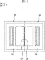
FIG. 2 is a top plan view showing the unfolded state of a base jig and a bending jig which are main parts of a pouch bending guide apparatus for a secondary battery packaging system according to the present disclosure, and a state in which a pouch sheet is placed by being unfolded on the base jig and the bending jig. -
FIG. 3 is a perspective view showing a portion of the bending jig shown inFIG. 2 . -
FIG. 4 is a perspective view showing a portion of the base jig shown inFIG. 2 . -
FIG. 5 is a perspective view showing a bending knife which is a main part of the pouch bending guide apparatus of the present disclosure. -
FIG. 6 is a rear view ofFIG. 5 . -
FIG. 7 a side view showing a state in which the bending knife is moved to the inside of the pouch sheet while the bending jig shown inFIG. 2 is folded toward the base jig. -
FIG. 8 is an enlarged side view showing a state before a stopper is in contact with the bending lateral surface of a pouch when forming the pouch by folding the pouch sheet shown inFIG. 7 . -
FIG. 9 is an enlarged side view showing a state in which the stopper is in contact with the bending lateral surface of the pouch when forming the pouch by folding the pouch sheet shown inFIG. 7 . - The present disclosure relates to a pouch bending guide apparatus for a secondary battery packaging system which folds a pouch sheet while the bending jig is folded toward the base jig with the pouch sheet placed on a base jig and a bending jig, the apparatus including a bending knife which supports, from the inside of a pouch, a bending lateral surface of the pouch formed while the pouch sheet is folded by the bending jig, wherein the bending knife is provided with a stopper, and while the pouch sheet is folded by the bending jig, the bending knife moves toward the inside of the pouch sheet such that a stopper supports the inner surface of the bending lateral surface of the pouch.
- The present disclosure relates to a pouch bending guide apparatus for a secondary battery packaging system which folds a
pouch sheet 2A while thebending jig 20 is folded toward thebase jig 30 with thepouch sheet 2A placed on abase jig 30 and abending jig 20. The pouch bending guide apparatus of the present disclosure is provided with abending knife 40 as a main part which supports, from the inside of a pouch, a bending lateral surface 2BS of thepouch 2 formed while thepouch sheet 2A is folded by thebending jig 20 such that the bending lateral surface 2BS of thepouch 2 is prevented from being pushed concavely inward, wherein thebending knife 40 is provided with astopper 42 which supports the bending lateral surface 2BS from the inner surface of the pouch. - The inner surface of the
base jig 30 is disposed to be directed upward. Thebase jig 30 is formed to have the shape of a rectangular plate. The inner surface of thebase jig 30 is provided with a pouch battery cell receiving part seating groove having the shape of a concave half groove. Thepouch sheet 2A for forming thepouch 2 in which a battery cell is mounted includes two half battery cell receiving parts relative to the center of thepouch sheet 2A, and each of the half battery cell receiving parts of the pouch has the shape of a rectangular groove protruding outward from thepouch sheet 2A, and thus a half pouch battery cell receiving part seating groove of thebase jig 30 is formed to have the shape of a rectangular groove such that the half battery cell receiving part is seated in the half pouch battery cell receiving part seating groove. - The
bending jig 20 is supported by a support frame and is folded toward or unfolded from the inner surface of thebase jig 30 by a bending operation unit (not shown). Even the inner surface of thebending jig 20 is provided with a concave half pouch battery cell receiving part seating groove. The pouch battery cell receiving part seating groove of thebending jig 20 also has the shape of a rectangular groove. - The
base jig 30 is mounted to the support frame, and side walls of thebase jig 30 and thebending jig 20 are coupled to each other by a hinge part. The inner surface of thebase jig 30 and thebending jig 20 are disposed to face each other by folding thebending jig 20 toward the inner surface of thebase jig 30, and thebending jig 20 is unfolded outward from the inner surface of thebase jig 30. Each of thebase jig 30 and thebending jig 20 is formed to have the shape of a plate having a pouch battery cell receiving part seating groove provided therein. Thebending jig 20 is folded toward and unfolded from thebase jig 30 relative to the hinge part. - While the
bending jig 20 is unfolded from thebase jig 30, the inner surface of thebending jig 20 is disposed to be directed upward. - A vacuum suction passage is formed inside each of the
base jig 30 and thebending jig 20, and a plurality of vacuum suction holes communicating with the vacuum suction passage is formed in each of the inner surfaces of thebase jig 30 and thebending jig 20 facing each other. The vacuum suction holes of thebase jig 30 are connected with the vacuum suction passage of the inside of thebase jig 30 and are open to the inner surface of thebase jig 30. Additionally, the vacuum suction holes of thebending jig 20 are also connected with the vacuum suction passage of the inside of thebending jig 20 and are open to the inner surface of thebending jig 20. - The outer surface of the
pouch sheet 2A placed on the inner surfaces of thebase jig 30 and thebending jig 20 is disposed to face the vacuum suction holes of thebase jig 30 and the vacuum suction holes of thebending jig 20. - The vacuum suction passage of the inside of the
base jig 30 and the vacuum suction holes thereof, and the vacuum suction passage of the inside of thebending jig 20 and the vacuum suction holes thereof are connected with a vacuum device, which is not shown, by a connecting hose, a vacuum connection block, and a vacuum pressure charging block. Air is suctioned through the vacuum suction holes of the inner surface of thebase jig 30 and the vacuum suction holes of the inner surface of thebending jig 20 by the vacuum device such that thepouch sheet 2A can be in close contact with the inner surface of thebase jig 30 and the inner surface of thebending jig 20 by vacuum. - The vacuum device is connected with the vacuum suction passages of the
base jig 30 and thebending jig 20 by a connection means such as a hose not shown, and while thepouch sheet 2A is suctioned on thebase jig 30 and thebending jig 20 by the operation of the vacuum device, thebending jig 20 is folded toward or unfolded from thebase jig 30 relative to the hinge part. Of course, the folding and unfolding operations of thebending jig 20 toward thebase jig 30 may be performed by a bending operation means not shown. The bending operation means may use a known device such as a cylinder, and thus a detailed description thereof will be omitted. - The
pouch sheet 2A is placed on thebase jig 30 and the bendingjig 20, and a battery cell is received in a half battery cell receiving part disposed on thebase jig 30 among the pair of half battery cell receiving parts of thepouch sheet 2A, and while the two half battery cell receiving parts of thepouch sheet 2A are seated respectively in the pouch battery cell receiving part seating groove inside thebase jig 30 and the pouch battery cell receiving part seating groove of the bendingjig 20, thepouch sheet 2A is folded while the bendingjig 20 is folded toward thebase jig 30, and after thepouch sheet 2A is folded, thepouch 2 having the battery cell mounted in the half battery cell receiving part inside thepouch 2 is formed. Of course, while the two half battery cell receiving parts of thepouch sheet 2A are empty without battery cells, thepouch 2 may be formed by folding thepouch sheet 2A in half relative to the center of thepouch sheet 2A, and one side surface of even apouch 2 without battery cells is formed as a folding side surface. - In this case, one side wall of the
base jig 30 and one side wall of the bendingjig 20 are connected to each other by the hinge part, and a bending guide opening part OP is formed on each of the side walls of thebase jig 30 and the bendingjig 20 such that the inner and outer surfaces of the side wall communicate with each other. The bending guide opening part OP is formed on each of the one side wall of thebase jig 30 and the one side wall of the bendingjig 20. The bending guide opening part OP is formed by passing through the side wall of each of thebase jig 30 and the bendingjig 20 from one side surface of the pouch battery cell receiving part seating groove formed inside each of thebase jig 30 and the bendingjig 20. The bending guide opening parts OP may be considered as guide holes to guide the bending lateral surface 2BS of thepouch 2 to be pushed to the outside when thestopper 42 to be described later pushes the inner surface of the bending lateral surface such that the bending lateral surface 2BS of thepouch 2 is prevented from being pushed to the inside of thepouch 2. - The pouch bending guide apparatus of the present disclosure is provided with the bending
knife 40 which supports the bending lateral surface 2BS of thepouch 2 from the inside thereof when thepouch sheet 2A is folded. - When the base jig 3 and the bending
jig 20 stop after moving along a movement path, the bendingjig 20 is folded toward thebase jig 30. In a case in which the movement path is a track, when thebase jig 30 and the bendingjig 20 stop after moving along the track, the bendingjig 20 is folded toward thebase jig 30. In a case in which the movement path is a turntable, when thebase jig 30 and the bendingjig 20 mounted to the turntable stop after moving according to the rotation of the turntable, the bendingjig 20 is folded toward thebase jig 30. - A bending
knife frame 50 is disposed at a side of the movement path. When the movement path is a turntable, the bendingknife frame 50 is disposed next to the turntable. Alift drive motor 54 is mounted to the bendingknife frame 50. The motor shaft of thelift drive motor 54 is arranged in a vertical direction. The motor shaft of thelift drive motor 54 is provided with a lifting ball screw. - The bending
knife frame 50 is provided with an LM guide. The LM guide is provided with a guide rail and a guide rail block, and the guide rail is arranged in a direction perpendicular to the bendingknife frame 50. The guide rail block is coupled slidably to the guide rail. When the bendingknife frame 50 is seen from the front, the guide rail is seen to include a pair of guide rails arranged respectively at left and right sides to be in parallel to each other. - A bending
knife support frame 60 is coupled to the bendingknife frame 50. The bendingknife support frame 60 is coupled to the bendingknife frame 50 such that the bendingknife support frame 60 is moved upward and downward by the LM guide. The bendingknife frame 50 is coupled to the guide rail block of the LM guide, and the bendingknife support frame 60 is coupled to the bendingknife frame 50 to move upward and downward. - The bending
knife support frame 60 is provided with a lift ball screw nut. The lift ball screw nut is preferably provided on the center part of the lower surface of the bendingknife support frame 60. The motor shaft of thelift drive motor 54 provided on the bendingknife frame 50 is provided with the lifting ball screw, and the lifting ball screw nut provided in the bendingknife support frame 60 is coupled to the lifting ball screw. Accordingly, as the motor shaft of the drive motor rotates, the bendingknife support frame 60 may be raised and lowered on the bendingknife frame 50 by the lifting ball screw and the lift ball screw nut. - The bending
knife support frame 60 is provided with an LM guide. Aninclined frame 62 is provided on the upper part of the bendingknife support frame 60. When seen from the side of the bendingknife support frame 60, the front end part of theinclined frame 62 is disposed to be lower than a base end part. That is, the rear side of theinclined frame 62 is disposed to be inclined such that the rear side of the inclined frame is raised higher than the front side thereof. Theinclined frame 62 is provided with an LM guide. The LM guide provided on theinclined frame 62 is composed of a pair of guide rails and a guide rail block. When seen from the upper side of theinclined frame 62, the pair of guide rails disposed side by side at left and right sides is provided in theinclined frame 62. The pair of guide rails extends along the longitudinal direction of theinclined frame 62. The guide rail block is coupled slidably to the pair of guide rails. - The
drive motor 64 is mounted to the base end part of theinclined frame 62. Since theinclined frame 62 is a component of the bendingknife support frame 60, thedrive motor 64 is configured to be mounted to the bendingknife support frame 60. The motor shaft of thedrive motor 64 is provided with a ball screw. The ball screw BS provided in the motor shaft of thedrive motor 64 extends along the longitudinal direction of theinclined frame 62. - A moving frame is coupled to the LM guide provided in the
inclined frame 62 of the bendingknife support frame 60. The moving frame is coupled to the guide rail block coupled slidably to the guide rails of theinclined frame 62. The moving frame may slide on theinclined frame 62 of the bendingknife support frame 60 due to the LM guide. That is, the moving frame may move forward and rearward on theinclined frame 62 of the bendingknife support frame 60. The moving frame is configured to move forward and rearward at an inclined state on the bendingknife support frame 60. - The
drive motor 64 is mounted to theinclined frame 62, and the motor shaft of thedrive motor 64 is provided with the ball screw BS, and the moving frame is provided with the ball screw nut BSN, and the ball screw nut BSN is coupled to the ball screw BS. Accordingly, as the motor shaft and ball screw BS of thedrive motor 64 mounted to theinclined frame 62 rotate, the ball screw nut BSN moves rectilinearly along the ball screw BS such that the moving frame can move to the front and rear sides of theinclined frame 62. The moving frame may move forward and rearward at an inclined state thereof on the bendingknife support frame 60. - The moving frame is provided with the bending
knife 40. The bendingknife 40 is formed to have a plate shape. The bendingknife 40 is mounted to the moving frame and thus is disposed to be inclined such that the front side of the bendingknife 40 is lower than the rear side thereof. In this case, the front lower surface of the bendingknife 40 is formed as a horizontal surface. When the bendingknife 40 is seen from a side thereof in a state in which the bendingknife 40 is coupled to the moving frame, the front lower surface of the bendingknife 40 is formed as a horizontal surface. - The bending
knife 40 is provided with thestopper 42 so as to support the inner surface of the bending lateral surface 2BS of thepouch 2. The bendingknife 40 includes a stopper seating groove such that the inside of the stopper seating groove and the upper surface of the bending knife communicate with each other, and thestopper 42 is seated in and coupled to the stopper seating groove. Thestopper 42 protrudes more forward than the front of the bendingknife 40. The front end part of thestopper 42 may be formed as a curved surface or a flat surface. The bending guide opening part OP is formed in each of the side walls of thebase jig 30 and the bendingjig 20 such that the inner and outer surfaces of the side wall communicate with each other, and thestopper 42 may be configured to have a width equal to or slightly smaller than the width of the bending guide opening part OP. - Meanwhile, according to the present disclosure, there is proposed a pouch bending method for a secondary battery packaging system, the method including: bending the pouch by folding the
pouch sheet 2A while the bendingjig 20 is folded toward thebase jig 30 with thepouch sheet 2A placed on thebase jig 30 and the bendingjig 20; and supporting the bending lateral surface 2BS of thepouch 2 formed while thepouch sheet 2A is bent, from the inside of thepouch 2, by moving the bendingknife 40 toward the inside of thepouch sheet 2A folded while thepouch sheet 2A is folded by the bendingjig 20. - According to the pouch bending guide apparatus of the present disclosure having the above configuration, the bending
knife 40 is provided with thestopper 42, and while thepouch sheet 2A is folded by the bendingjig 20, the bendingknife 40 is moved to the inside of thepouch sheet 2A such that thestopper 42 supports the inner surface of the bending lateral surface 2BS of thepouch 2. - Specifically, the
base jig 30 and the bendingjig 20 are unfolded relative to the hinge part by which thebase jig 30 and the bendingjig 20 are connected to each other, and thepouch sheet 2A is unfolded on the unfolded inner surfaces of thebase jig 30 and the bendingjig 20, and in this state, when the bendingjig 20 is folded toward thebase jig 30 relative to the hinge part, thepouch sheet 2A, which is unfolded, is also folded in half. This is the bending of the pouch. - When the bending
jig 20 and ahalf pouch sheet 2A are folded toward thebase jig 30 and a remaininghalf pouch sheet 2A, the bendingknife 40 moves forward to the inside of thefolding pouch sheet 2A. As the motor shaft and ball screw of the drive motor mounted to theinclined frame 62 of the bendingknife support frame 60 rotate in one direction, the moving frame is moved forward by the ball screw nut and the ball screw, and the bendingknife 40 mounted to the moving frame is moved forward to be moved to the inside of thepouch sheet 2A. With the bendingjig 20 folded toward thebase jig 30 at least in an acute angle, the bendingknife 40 moves forward to the inside of thepouch sheet 2A. - The bending
knife 40 moves to the inside of thefolding pouch sheet 2A, and thestopper 42 provided on the bendingknife 40 supports the bending lateral surface 2BS of thepouch 2 from the inner surface of thepouch 2. The area of the bending lateral surface 2BS of thepouch 2 pushed by thestopper 42 during the bending of thepouch 2 is increased such that thestopper 42 pushes many areas of the bending lateral surface 2BS. This is supporting the bending lateral surface of the pouch. - Accordingly, since the
stopper 42 supports the bending lateral surface 2BS of thepouch 2 from the inner surface thereof, the bending lateral surface 2BS of thepouch 2 is prevented from being pushed inward. The front end part of thestopper 42 may be formed as a curved surface or a flat surface, and the curved or flat surface of thestopper 42 supports the bending lateral surface 2BS of thepouch 2 from the inside of thepouch 2. In this case, the bending guide opening part OP is formed in one side wall of each of thebase jig 30 and the bendingjig 20 such that the inner and outer surfaces of the side wall communicate with each other, and thestopper 42 of the bendingknife 40 pushes the bending lateral surface 2BS of thepouch 2 outward through the bending guide opening parts, so the bending lateral surface 2BS of thepouch 2 can be prevented from being pushed inward. Thestopper 42 pushes the bending lateral surface 2BS outward, and thus thepouch 2 in which the bending lateral surface 2BS is prevented from being pushed inward is formed. - Meanwhile, in a state in which the bending
jig 20 and thehalf pouch sheet 2A are folded to be close to the upper surface of the bendingknife 40, the bendingknife 40 and thestopper 42 move rearward out of the bendingjig 20 and thehalf pouch sheet 2A. As the motor shaft and ball screw BS of thedrive motor 64 mounted to theinclined frame 62 of the bendingknife support frame 60 rotate in different directions, the moving frame is moved rearward by the ball screw nut BSN and the ball screw BS, and the bendingknife 40 and thestopper 42 mounted to the moving frame are moved rearward to be moved to the outside of thepouch sheet 2A from the inside thereof. While the bendingjig 20 and thehalf pouch sheet 2A are folded to be close to the upper surface of the bendingknife 40, the bending lateral surface 2BS of thepouch 2 is prevented from being pushed to the inside of thepouch 2. Accordingly, in the state in which the bendingjig 20 and thehalf pouch sheet 2A are folded to be close to the upper surface of the bendingknife 40, the bendingknife 40 and thestopper 42 move rearward out of the bendingjig 20 and thehalf pouch sheet 2A. After the bendingknife 40 and thestopper 42 move out of the bendingjig 20 and thehalf pouch sheet 2A, the bendingjig 2 and thehalf pouch sheet 2A are completely folded toward thebase jig 30 and the remaininghalf pouch sheet 2A, so that thepouch 2 in which the twohalf pouch sheets 2A are laid on each other can be formed. - Accordingly, in the pouch bending guide apparatus of the present disclosure, while folding and bending the center part of the
pouch sheet 2A, the center part of thepouch sheet 2A is prevented from being pushed inward, thereby preventing the bending lateral surface 2BS of thepouch 2 from being deformed concavely inward. That is, when thepouch sheet 2A is folded, the bending lateral surface 2BS of thepouch 2 is prevented from being pushed inward and collapsing into a concave shape. - In a conventional technology, as for a battery without a bottom, when the
pouch 2 is bent, thepouch 2 is moved into the main chamber, resulting in the problem that the size of the main chamber decreases. - However, in the pouch bending guide apparatus of the present disclosure, the
stopper 42 is coupled to the knife and the jigs (that is, thebase jig 30 and the bending jig 20) and prevents thepouch 2 from being pushed into the main chamber. That thepouch 2 is pushed into the main chamber means that the bending lateral surface 2BS on one side of thepouch 2 is pushed into thepouch 2 when forming thepouch 2 by folding thepouch sheet 2A. According to the present disclosure, during the bending of thepouch 2, thepouch 2 is prevented from being moved into the main chamber, thereby preventing the size of the main chamber of thepouch 2 from decreasing. - The bending lateral surface 2BS of the
pouch 2 is prevented from being pushed inward, thereby improving the exterior quality and reliability of thepouch 2. - In addition, the pouch bending guide apparatus of the present disclosure solves the problem that heat generated during the charging/discharging of the battery cells of a secondary battery is not efficiently discharged when the bending lateral surface 2BS of the
pouch 2 having battery cells mounted therein is deformed concavely inward. A plurality ofpouches 2 having battery cells mounted therein (hereinafter, referred to as thepouch 2 for convenience) is placed by standing side by side on a hanger frame, and the bending lateral surface 2BS of each of thepouches 2 is in contact with a heat sink provided on the lower part of the hanger frame. In this state, heat generated in thepouch 2 during the charging/discharging of the battery cell is transmitted from the bending lateral surface 2BS to the heat sink to be discharged. Thepouch 2 does not have a concave deformation part formed in such a manner that the bending lateral surface 2BS of thepouch 2 is recessed inward, and thus the bending lateral surface of thepouch 2 is not prevented from being efficiently in contact with the heat sink. The bending lateral surface of thepouch 2 is at least formed to protrude or be flat at the side of thepouch 2, and thus the bending lateral surface 2BS of thepouch 2 is securely in contact with the heat sink, and accordingly, heat generated in thepouch 2 during the charging/discharging of the battery cell is efficiently transmitted from the bending lateral surface 2BS to the heat sink, thereby efficiently discharging heat generated inside thepouch 2 during the charging/discharging of the battery cell. - In addition, heat discharge from the
pouch 2 is efficiently performed, thereby preventing the battery cell from deteriorating or burning due to heat. - Furthermore, according to the present disclosure, the bending
knife 40 is mounted to the bendingknife support frame 60, and the bendingknife support frame 60 is mounted to a bending guide frame such that the bendingknife support frame 60 can be moved upward and downward, and thus the vertical position of the bendingknife 40 and the vertical position of thestopper 42 of the bendingknife 40 can be adjusted according to working conditions, thereby further facilitating the bending of thepouch 2. - Additionally, the front lower surface of the bending
knife 40 is configured as a horizontal surface, and thus when the bendingknife 40 moves to and from the inside of thefolding pouch sheet 2A, the front lower surface of the bendingknife 40 is prevented from being held in thepouch sheet 2A, thereby further facilitating the formation of thepouch 2 by bending thepouch sheet 2A. - The present disclosure relates to the pouch bending guide apparatus, for a secondary battery packaging system, which folds the pouch sheet while the bending jig is folded toward the base jig with the pouch sheet placed on the base jig and the bending jig, the apparatus including: the bending knife which supports, from the inside of the pouch, the bending lateral surface of the pouch formed while the pouch sheet is folded by the bending jig and has industrial applicability.
Claims (9)
- A pouch bending guide apparatus, for a secondary battery packaging system, which folds a pouch sheet (2A) while a bending jig (20) is folded toward a base jig (30) with the pouch sheet (2A) placed on the base jig (30) and the bending jig (20), the apparatus comprising:
a bending knife (40) which supports, from an inside of a pouch (2), a bending lateral surface (2BS) of the pouch (2) formed while the pouch sheet (2A) is folded by the bending jig (20) . - The apparatus of claim 1, wherein the bending knife (40) is provided with a stopper (42) to support an inner surface of the bending lateral surface (2BS) of the pouch (2).
- The apparatus of claim 2, wherein the bending knife (40) is configured to be moved toward an inside of the pouch sheet (2A) by a movement means such that the stopper (42) prevents movement of the bending lateral surface (2BS) to the inside of the pouch (2).
- The apparatus of claim 3, wherein the bending knife (40) is disposed to be inclined, and when the bending jig (20) and the pouch sheet (2A) are folded, the inclined bending knife (40) is configured to be moved toward the inside of the pouch sheet (2A) by the movement means.
- The apparatus of claim 1, wherein one side wall of the base jig (30) and one side wall of the bending jig (20) are connected to each other by a hinge part, and a bending guide opening part (OP) is formed in each of the side walls of the base jig (30) and the bending jig (20) such that inner and outer surfaces of the side wall communicate with each other.
- The apparatus of claim 1, wherein the pouch sheet (2A) is placed on the base jig (30) and the bending jig (20), and in a state in which a battery cell is received in a half battery cell receiving part disposed on the base jig (30) among a pair of half battery cell receiving parts of the pouch sheet (2A), the pouch sheet (2A) is folded while the bending jig (20) is folded toward the base jig (30), and after the pouch sheet (2A) is folded, the pouch (2) having the battery cell mounted in the half battery cell receiving part inside the pouch (2) is formed, wherein the bending knife (40) is configured to move to the inside of the pouch sheet (2A) and to support the bending lateral surface (2BS) of the pouch (2) from the inside of the pouch (2) while the pouch sheet (2A) is folded.
- The apparatus of claim 1, wherein a vacuum suction passage is formed inside each of the base jig (30) and the bending jig (20), and a plurality of vacuum suction holes communicating with the vacuum suction passage is formed in each of inner surfaces of the base jig (30) and the bending jig (20) facing each other.
- The apparatus of claim 7, wherein in a state in which the pouch sheet (2A) placed on the inner surfaces of the base jig (30) and the bending jig (20) is vacuum-suctioned by the vacuum suction holes of the base jig (30) and the bending jig (20), the pouch sheet (2A) is folded in half by folding the bending jig (20) toward the inner surface of the base jig (30), and thus the pouch (2) is formed, and a battery cell is mounted in a battery cell receiving part inside the pouch (2).
- A pouch bending method for a secondary battery packaging system, the method comprising:bending a pouch (2) by folding a pouch sheet (2A) while a bending jig (20) is folded toward a base jig (30) with the pouch sheet (2A) placed on the base jig (30) and the bending jig (20) ; andsupporting a bending lateral surface (2BS) of the pouch (2) formed while the pouch sheet (2A) is bent, from an inside of the pouch (2), by moving a bending knife (40) toward an inside of the pouch sheet (2A) folded while the pouch sheet (2A) is folded by the bending jig (20).
Applications Claiming Priority (2)
| Application Number | Priority Date | Filing Date | Title |
|---|---|---|---|
| KR1020200040222A KR102304212B1 (en) | 2020-04-02 | 2020-04-02 | Battery cell pouch bending apparaus for secondary battery packaging system and pouch bending method |
| PCT/KR2020/008021 WO2021201337A1 (en) | 2020-04-02 | 2020-06-20 | Pouch bending guide apparatus and pouch bending method for secondary battery packaging system |
Publications (3)
| Publication Number | Publication Date |
|---|---|
| EP4129624A1 true EP4129624A1 (en) | 2023-02-08 |
| EP4129624A4 EP4129624A4 (en) | 2024-04-03 |
| EP4129624B1 EP4129624B1 (en) | 2025-03-26 |
Family
ID=77914476
Family Applications (1)
| Application Number | Title | Priority Date | Filing Date |
|---|---|---|---|
| EP20929169.9A Active EP4129624B1 (en) | 2020-04-02 | 2020-06-20 | Pouch bending guide apparatus and pouch bending method for secondary battery packaging system |
Country Status (7)
| Country | Link |
|---|---|
| US (1) | US20230163343A1 (en) |
| EP (1) | EP4129624B1 (en) |
| KR (1) | KR102304212B1 (en) |
| CN (1) | CN116323149B (en) |
| HU (1) | HUE071757T2 (en) |
| PL (1) | PL4129624T3 (en) |
| WO (1) | WO2021201337A1 (en) |
Families Citing this family (3)
| Publication number | Priority date | Publication date | Assignee | Title |
|---|---|---|---|---|
| KR102281744B1 (en) * | 2019-10-02 | 2021-07-26 | 주식회사 엠플러스 | Vacuum carrier |
| CN114497677A (en) * | 2022-01-18 | 2022-05-13 | 中山市众旺德新能源科技有限公司 | A kind of manufacturing method of double pit soft pack battery |
| KR102878092B1 (en) * | 2022-07-14 | 2025-10-29 | 주식회사 엠플러스 | Battery cell pouch bending unit for secondary battery packaging system with increased bending structure and pouch bending method thereby |
Family Cites Families (20)
| Publication number | Priority date | Publication date | Assignee | Title |
|---|---|---|---|---|
| US2696241A (en) * | 1950-07-03 | 1954-12-07 | Northrop Aircraft Inc | Wrap-stretch means |
| JP3544183B2 (en) * | 2001-03-16 | 2004-07-21 | トキワ精機株式会社 | Apparatus and method for manufacturing thick curved tube |
| US6908583B2 (en) * | 2003-03-14 | 2005-06-21 | Motorola, Inc. | System and method for bending a substantially rigid substrate |
| KR20130048419A (en) | 2011-11-02 | 2013-05-10 | 에스케이이노베이션 주식회사 | Secondary battery in pouch type |
| KR101603074B1 (en) * | 2013-09-27 | 2016-03-14 | 주식회사 엘지화학 | Folding Device for Battery Cell having Heating Member |
| KR101785138B1 (en) * | 2013-10-31 | 2017-10-12 | 주식회사 엘지화학 | Pcm folding apparatus of battery and pcm folding method using the same |
| KR20150003358U (en) | 2014-03-03 | 2015-09-11 | 주식회사 엘지화학 | Secondary Battery Pouch |
| KR101843823B1 (en) * | 2014-10-28 | 2018-03-30 | 주식회사 엘지화학 | Apparatus Transferring Battery Cell |
| KR101672402B1 (en) * | 2015-07-21 | 2016-11-03 | (주)휴민텍 | Acute angle bending apparatus for side sealing portion of pouch type secondary battery cell and acute angle bending method using the same |
| KR102261691B1 (en) * | 2015-07-22 | 2021-06-08 | 주식회사 엘지에너지솔루션 | Irregular Battery Cell with Transformable Structure |
| US9882179B2 (en) * | 2015-07-29 | 2018-01-30 | Semiconductor Energy Laboratory Co., Ltd. | Secondary battery and electronic device including secondary battery |
| KR102088214B1 (en) * | 2016-01-26 | 2020-03-12 | 주식회사 엘지화학 | Device for Manufacturing Battery Cell Having One-Stop Folding Member |
| KR101858680B1 (en) * | 2016-08-11 | 2018-05-16 | (주)테크랜드 | Apparatus and method for folding cells of secondary cell battery |
| KR102169839B1 (en) * | 2016-09-08 | 2020-10-26 | 주식회사 엘지화학 | Battery Case Sealing Device Having Wrinkle Removal Function |
| KR102203400B1 (en) * | 2016-12-23 | 2021-01-15 | 주식회사 엘지화학 | The jig for battery cell attached |
| KR102217451B1 (en) * | 2017-08-29 | 2021-02-22 | 주식회사 엘지화학 | Rechargeable battery and the manufacturing method, and press block for rechargeable battery |
| KR102267588B1 (en) * | 2017-09-26 | 2021-06-18 | 주식회사 엘지에너지솔루션 | Bending Device for Current Breaking Member of Battery Pack |
| KR101903367B1 (en) * | 2017-10-26 | 2018-10-02 | 주식회사 디에이테크놀로지 | Protection Film Packaging Apparatus for Secondary Cell |
| KR102495887B1 (en) * | 2019-04-16 | 2023-02-06 | 주식회사 엘지에너지솔루션 | The Apparatus And The Method For Manufacturing Secondary Battery |
| KR102015898B1 (en) * | 2019-04-25 | 2019-08-28 | 백영진 | Folding Device for electrode lead Part of Battery Cell |
-
2020
- 2020-04-02 KR KR1020200040222A patent/KR102304212B1/en active Active
- 2020-06-20 CN CN202080101453.7A patent/CN116323149B/en active Active
- 2020-06-20 WO PCT/KR2020/008021 patent/WO2021201337A1/en not_active Ceased
- 2020-06-20 HU HUE20929169A patent/HUE071757T2/en unknown
- 2020-06-20 PL PL20929169.9T patent/PL4129624T3/en unknown
- 2020-06-20 EP EP20929169.9A patent/EP4129624B1/en active Active
-
2022
- 2022-10-03 US US17/959,277 patent/US20230163343A1/en active Pending
Also Published As
| Publication number | Publication date |
|---|---|
| CN116323149A (en) | 2023-06-23 |
| EP4129624B1 (en) | 2025-03-26 |
| US20230163343A1 (en) | 2023-05-25 |
| KR102304212B9 (en) | 2023-01-13 |
| HUE071757T2 (en) | 2025-09-28 |
| WO2021201337A1 (en) | 2021-10-07 |
| CN116323149B (en) | 2025-09-30 |
| PL4129624T3 (en) | 2025-08-04 |
| EP4129624A4 (en) | 2024-04-03 |
| KR102304212B1 (en) | 2021-09-24 |
Similar Documents
| Publication | Publication Date | Title |
|---|---|---|
| US20230163343A1 (en) | Battery cell pouch bending apparatus for secondary battery packaging system and pouch bending method | |
| KR102763834B1 (en) | Apparatus for manufacturing pouch type secondary battery | |
| KR102649307B1 (en) | Secondary battery production system and method of the same | |
| KR101289429B1 (en) | Battery pack assembly unit | |
| CN205406651U (en) | Soft packet of secondary cell changes into system | |
| WO2025218081A1 (en) | Electrolyte injection device, battery production line, and electrolyte injection method | |
| CN118387596A (en) | Automatic feeding and discharging equipment for soft-package cylindrical lithium battery and production line of automatic feeding and discharging equipment | |
| KR102311430B1 (en) | Battery cell pouch bending unit for secondary battery packaging system and pouch bending method | |
| KR100995474B1 (en) | Connection lead welding device for lithium secondary battery | |
| CN115890086A (en) | Welding equipment and welding method | |
| US20240363891A1 (en) | Battery module stacking device and method, and battery production system | |
| CN112072152A (en) | Vertical air-extracting packaging machine for soft package battery and vertical air-extracting sealing method for soft package battery | |
| CN117020412B (en) | Welding equipment and welding method | |
| KR102304208B1 (en) | Battery cell pouch bending apparaus for secondary battery packaging system utilizing stopping means and pouch bending method | |
| CN210335997U (en) | Anti-adhesion lithium battery pole piece supply device | |
| CN119500873B (en) | Lithium battery tab welding and printing leveling process and device | |
| KR20210101126A (en) | Apparatus for automatic folding | |
| KR102878092B1 (en) | Battery cell pouch bending unit for secondary battery packaging system with increased bending structure and pouch bending method thereby | |
| CN113363655A (en) | Secondary packaging device and secondary packaging method for soft package battery | |
| CN120854685B (en) | Manipulator for welding battery cell electrode lug and nickel sheet and battery cell assembling machine thereof | |
| CN222214228U (en) | Battery packaging device and battery processing equipment | |
| JP2023034753A (en) | Power storage module | |
| KR20250054543A (en) | Apparatus and method of sealing secondary battery | |
| CN115312826A (en) | Secondary packaging device and packaging method for soft-packaged battery cell | |
| CN119703184A (en) | Milling head device for disassembling new energy battery packs |
Legal Events
| Date | Code | Title | Description |
|---|---|---|---|
| STAA | Information on the status of an ep patent application or granted ep patent |
Free format text: STATUS: THE INTERNATIONAL PUBLICATION HAS BEEN MADE |
|
| PUAI | Public reference made under article 153(3) epc to a published international application that has entered the european phase |
Free format text: ORIGINAL CODE: 0009012 |
|
| STAA | Information on the status of an ep patent application or granted ep patent |
Free format text: STATUS: REQUEST FOR EXAMINATION WAS MADE |
|
| 17P | Request for examination filed |
Effective date: 20221031 |
|
| AK | Designated contracting states |
Kind code of ref document: A1 Designated state(s): AL AT BE BG CH CY CZ DE DK EE ES FI FR GB GR HR HU IE IS IT LI LT LU LV MC MK MT NL NO PL PT RO RS SE SI SK SM TR |
|
| RIN1 | Information on inventor provided before grant (corrected) |
Inventor name: PARK, SANG JUN Inventor name: KIM, WOOK KYOUNG Inventor name: AHN, JI EUN Inventor name: JEONG, BONG UK Inventor name: PARK, HUI JIN Inventor name: KIM, JONG SUNG |
|
| RAP1 | Party data changed (applicant data changed or rights of an application transferred) |
Owner name: SK ON CO., LTD. |
|
| DAV | Request for validation of the european patent (deleted) | ||
| DAX | Request for extension of the european patent (deleted) | ||
| A4 | Supplementary search report drawn up and despatched |
Effective date: 20240305 |
|
| RIC1 | Information provided on ipc code assigned before grant |
Ipc: B21D 11/20 20060101ALN20240228BHEP Ipc: H01M 50/183 20210101ALI20240228BHEP Ipc: B21D 19/08 20060101ALI20240228BHEP Ipc: B21D 19/12 20060101ALI20240228BHEP Ipc: B21D 19/02 20060101ALI20240228BHEP Ipc: H01M 50/20 20210101ALI20240228BHEP Ipc: H01M 10/04 20060101ALI20240228BHEP Ipc: H01M 50/10 20210101ALI20240228BHEP Ipc: B29C 53/80 20060101ALI20240228BHEP Ipc: B29C 53/04 20060101AFI20240228BHEP |
|
| GRAP | Despatch of communication of intention to grant a patent |
Free format text: ORIGINAL CODE: EPIDOSNIGR1 |
|
| STAA | Information on the status of an ep patent application or granted ep patent |
Free format text: STATUS: GRANT OF PATENT IS INTENDED |
|
| RIC1 | Information provided on ipc code assigned before grant |
Ipc: B21D 11/20 20060101ALN20241209BHEP Ipc: H01M 50/183 20210101ALI20241209BHEP Ipc: B21D 19/08 20060101ALI20241209BHEP Ipc: B21D 19/12 20060101ALI20241209BHEP Ipc: B21D 19/02 20060101ALI20241209BHEP Ipc: H01M 50/20 20210101ALI20241209BHEP Ipc: H01M 10/04 20060101ALI20241209BHEP Ipc: H01M 50/105 20210101ALI20241209BHEP Ipc: B29C 53/80 20060101ALI20241209BHEP Ipc: B29C 53/04 20060101AFI20241209BHEP |
|
| INTG | Intention to grant announced |
Effective date: 20241219 |
|
| GRAS | Grant fee paid |
Free format text: ORIGINAL CODE: EPIDOSNIGR3 |
|
| GRAA | (expected) grant |
Free format text: ORIGINAL CODE: 0009210 |
|
| STAA | Information on the status of an ep patent application or granted ep patent |
Free format text: STATUS: THE PATENT HAS BEEN GRANTED |
|
| AK | Designated contracting states |
Kind code of ref document: B1 Designated state(s): AL AT BE BG CH CY CZ DE DK EE ES FI FR GB GR HR HU IE IS IT LI LT LU LV MC MK MT NL NO PL PT RO RS SE SI SK SM TR |
|
| REG | Reference to a national code |
Ref country code: GB Ref legal event code: FG4D |
|
| REG | Reference to a national code |
Ref country code: CH Ref legal event code: EP |
|
| REG | Reference to a national code |
Ref country code: DE Ref legal event code: R096 Ref document number: 602020048548 Country of ref document: DE |
|
| REG | Reference to a national code |
Ref country code: IE Ref legal event code: FG4D |
|
| PG25 | Lapsed in a contracting state [announced via postgrant information from national office to epo] |
Ref country code: RS Free format text: LAPSE BECAUSE OF FAILURE TO SUBMIT A TRANSLATION OF THE DESCRIPTION OR TO PAY THE FEE WITHIN THE PRESCRIBED TIME-LIMIT Effective date: 20250626 |
|
| PG25 | Lapsed in a contracting state [announced via postgrant information from national office to epo] |
Ref country code: FI Free format text: LAPSE BECAUSE OF FAILURE TO SUBMIT A TRANSLATION OF THE DESCRIPTION OR TO PAY THE FEE WITHIN THE PRESCRIBED TIME-LIMIT Effective date: 20250326 |
|
| REG | Reference to a national code |
Ref country code: LT Ref legal event code: MG9D |
|
| PG25 | Lapsed in a contracting state [announced via postgrant information from national office to epo] |
Ref country code: NO Free format text: LAPSE BECAUSE OF FAILURE TO SUBMIT A TRANSLATION OF THE DESCRIPTION OR TO PAY THE FEE WITHIN THE PRESCRIBED TIME-LIMIT Effective date: 20250626 |
|
| PG25 | Lapsed in a contracting state [announced via postgrant information from national office to epo] |
Ref country code: HR Free format text: LAPSE BECAUSE OF FAILURE TO SUBMIT A TRANSLATION OF THE DESCRIPTION OR TO PAY THE FEE WITHIN THE PRESCRIBED TIME-LIMIT Effective date: 20250326 |
|
| PG25 | Lapsed in a contracting state [announced via postgrant information from national office to epo] |
Ref country code: LV Free format text: LAPSE BECAUSE OF FAILURE TO SUBMIT A TRANSLATION OF THE DESCRIPTION OR TO PAY THE FEE WITHIN THE PRESCRIBED TIME-LIMIT Effective date: 20250326 |
|
| PG25 | Lapsed in a contracting state [announced via postgrant information from national office to epo] |
Ref country code: GR Free format text: LAPSE BECAUSE OF FAILURE TO SUBMIT A TRANSLATION OF THE DESCRIPTION OR TO PAY THE FEE WITHIN THE PRESCRIBED TIME-LIMIT Effective date: 20250627 Ref country code: BG Free format text: LAPSE BECAUSE OF FAILURE TO SUBMIT A TRANSLATION OF THE DESCRIPTION OR TO PAY THE FEE WITHIN THE PRESCRIBED TIME-LIMIT Effective date: 20250326 |
|
| REG | Reference to a national code |
Ref country code: NL Ref legal event code: MP Effective date: 20250326 |
|
| PGFP | Annual fee paid to national office [announced via postgrant information from national office to epo] |
Ref country code: HU Payment date: 20250616 Year of fee payment: 6 |
|
| PG25 | Lapsed in a contracting state [announced via postgrant information from national office to epo] |
Ref country code: NL Free format text: LAPSE BECAUSE OF FAILURE TO SUBMIT A TRANSLATION OF THE DESCRIPTION OR TO PAY THE FEE WITHIN THE PRESCRIBED TIME-LIMIT Effective date: 20250326 |
|
| PG25 | Lapsed in a contracting state [announced via postgrant information from national office to epo] |
Ref country code: SE Free format text: LAPSE BECAUSE OF FAILURE TO SUBMIT A TRANSLATION OF THE DESCRIPTION OR TO PAY THE FEE WITHIN THE PRESCRIBED TIME-LIMIT Effective date: 20250326 |
|
| REG | Reference to a national code |
Ref country code: AT Ref legal event code: MK05 Ref document number: 1778639 Country of ref document: AT Kind code of ref document: T Effective date: 20250326 |
|
| REG | Reference to a national code |
Ref country code: HU Ref legal event code: AG4A Ref document number: E071757 Country of ref document: HU |
|
| PG25 | Lapsed in a contracting state [announced via postgrant information from national office to epo] |
Ref country code: SM Free format text: LAPSE BECAUSE OF FAILURE TO SUBMIT A TRANSLATION OF THE DESCRIPTION OR TO PAY THE FEE WITHIN THE PRESCRIBED TIME-LIMIT Effective date: 20250326 |
|
| PG25 | Lapsed in a contracting state [announced via postgrant information from national office to epo] |
Ref country code: ES Free format text: LAPSE BECAUSE OF FAILURE TO SUBMIT A TRANSLATION OF THE DESCRIPTION OR TO PAY THE FEE WITHIN THE PRESCRIBED TIME-LIMIT Effective date: 20250326 Ref country code: PT Free format text: LAPSE BECAUSE OF FAILURE TO SUBMIT A TRANSLATION OF THE DESCRIPTION OR TO PAY THE FEE WITHIN THE PRESCRIBED TIME-LIMIT Effective date: 20250728 |
|
| PGFP | Annual fee paid to national office [announced via postgrant information from national office to epo] |
Ref country code: DE Payment date: 20250626 Year of fee payment: 6 |
|
| PG25 | Lapsed in a contracting state [announced via postgrant information from national office to epo] |
Ref country code: IT Free format text: LAPSE BECAUSE OF FAILURE TO SUBMIT A TRANSLATION OF THE DESCRIPTION OR TO PAY THE FEE WITHIN THE PRESCRIBED TIME-LIMIT Effective date: 20250326 |
|
| PG25 | Lapsed in a contracting state [announced via postgrant information from national office to epo] |
Ref country code: AT Free format text: LAPSE BECAUSE OF FAILURE TO SUBMIT A TRANSLATION OF THE DESCRIPTION OR TO PAY THE FEE WITHIN THE PRESCRIBED TIME-LIMIT Effective date: 20250326 |
|
| PG25 | Lapsed in a contracting state [announced via postgrant information from national office to epo] |
Ref country code: EE Free format text: LAPSE BECAUSE OF FAILURE TO SUBMIT A TRANSLATION OF THE DESCRIPTION OR TO PAY THE FEE WITHIN THE PRESCRIBED TIME-LIMIT Effective date: 20250326 |
|
| PG25 | Lapsed in a contracting state [announced via postgrant information from national office to epo] |
Ref country code: RO Free format text: LAPSE BECAUSE OF FAILURE TO SUBMIT A TRANSLATION OF THE DESCRIPTION OR TO PAY THE FEE WITHIN THE PRESCRIBED TIME-LIMIT Effective date: 20250326 |
|
| PG25 | Lapsed in a contracting state [announced via postgrant information from national office to epo] |
Ref country code: SK Free format text: LAPSE BECAUSE OF FAILURE TO SUBMIT A TRANSLATION OF THE DESCRIPTION OR TO PAY THE FEE WITHIN THE PRESCRIBED TIME-LIMIT Effective date: 20250326 |
|
| PG25 | Lapsed in a contracting state [announced via postgrant information from national office to epo] |
Ref country code: IS Free format text: LAPSE BECAUSE OF FAILURE TO SUBMIT A TRANSLATION OF THE DESCRIPTION OR TO PAY THE FEE WITHIN THE PRESCRIBED TIME-LIMIT Effective date: 20250726 |
|
| REG | Reference to a national code |
Ref country code: DE Ref legal event code: R097 Ref document number: 602020048548 Country of ref document: DE |
|
| PG25 | Lapsed in a contracting state [announced via postgrant information from national office to epo] |
Ref country code: DK Free format text: LAPSE BECAUSE OF FAILURE TO SUBMIT A TRANSLATION OF THE DESCRIPTION OR TO PAY THE FEE WITHIN THE PRESCRIBED TIME-LIMIT Effective date: 20250326 |
|
| PG25 | Lapsed in a contracting state [announced via postgrant information from national office to epo] |
Ref country code: CZ Free format text: LAPSE BECAUSE OF FAILURE TO SUBMIT A TRANSLATION OF THE DESCRIPTION OR TO PAY THE FEE WITHIN THE PRESCRIBED TIME-LIMIT Effective date: 20250326 |
|
| REG | Reference to a national code |
Ref country code: CH Ref legal event code: H13 Free format text: ST27 STATUS EVENT CODE: U-0-0-H10-H13 (AS PROVIDED BY THE NATIONAL OFFICE) Effective date: 20260127 |
|
| PG25 | Lapsed in a contracting state [announced via postgrant information from national office to epo] |
Ref country code: MC Free format text: LAPSE BECAUSE OF FAILURE TO SUBMIT A TRANSLATION OF THE DESCRIPTION OR TO PAY THE FEE WITHIN THE PRESCRIBED TIME-LIMIT Effective date: 20250326 |
|
| PLBE | No opposition filed within time limit |
Free format text: ORIGINAL CODE: 0009261 |
|
| STAA | Information on the status of an ep patent application or granted ep patent |
Free format text: STATUS: NO OPPOSITION FILED WITHIN TIME LIMIT |
|
| REG | Reference to a national code |
Ref country code: CH Ref legal event code: L10 Free format text: ST27 STATUS EVENT CODE: U-0-0-L10-L00 (AS PROVIDED BY THE NATIONAL OFFICE) Effective date: 20260211 |
|
| PG25 | Lapsed in a contracting state [announced via postgrant information from national office to epo] |
Ref country code: LU Free format text: LAPSE BECAUSE OF NON-PAYMENT OF DUE FEES Effective date: 20250620 |
|
| GBPC | Gb: european patent ceased through non-payment of renewal fee |
Effective date: 20250626 |
|
| REG | Reference to a national code |
Ref country code: BE Ref legal event code: MM Effective date: 20250630 |
|
| 26N | No opposition filed |
Effective date: 20260105 |
|
| PG25 | Lapsed in a contracting state [announced via postgrant information from national office to epo] |
Ref country code: GB Free format text: LAPSE BECAUSE OF NON-PAYMENT OF DUE FEES Effective date: 20250626 |
|
| PG25 | Lapsed in a contracting state [announced via postgrant information from national office to epo] |
Ref country code: IE Free format text: LAPSE BECAUSE OF NON-PAYMENT OF DUE FEES Effective date: 20250620 |
|
| PG25 | Lapsed in a contracting state [announced via postgrant information from national office to epo] |
Ref country code: BE Free format text: LAPSE BECAUSE OF NON-PAYMENT OF DUE FEES Effective date: 20250630 |
|
| PG25 | Lapsed in a contracting state [announced via postgrant information from national office to epo] |
Ref country code: FR Free format text: LAPSE BECAUSE OF NON-PAYMENT OF DUE FEES Effective date: 20250630 |
|
| PG25 | Lapsed in a contracting state [announced via postgrant information from national office to epo] |
Ref country code: CH Free format text: LAPSE BECAUSE OF NON-PAYMENT OF DUE FEES Effective date: 20250630 |
|
| PGFP | Annual fee paid to national office [announced via postgrant information from national office to epo] |
Ref country code: PL Payment date: 20260325 Year of fee payment: 7 |