EP4129558A1 - Laser welding method and method for manufacturing electric rotating machine using same - Google Patents
Laser welding method and method for manufacturing electric rotating machine using same Download PDFInfo
- Publication number
- EP4129558A1 EP4129558A1 EP21795705.9A EP21795705A EP4129558A1 EP 4129558 A1 EP4129558 A1 EP 4129558A1 EP 21795705 A EP21795705 A EP 21795705A EP 4129558 A1 EP4129558 A1 EP 4129558A1
- Authority
- EP
- European Patent Office
- Prior art keywords
- laser light
- laser
- welding method
- conductor segments
- end portions
- Prior art date
- Legal status (The legal status is an assumption and is not a legal conclusion. Google has not performed a legal analysis and makes no representation as to the accuracy of the status listed.)
- Granted
Links
Images




Classifications
-
- B—PERFORMING OPERATIONS; TRANSPORTING
- B23—MACHINE TOOLS; METAL-WORKING NOT OTHERWISE PROVIDED FOR
- B23K—SOLDERING OR UNSOLDERING; WELDING; CLADDING OR PLATING BY SOLDERING OR WELDING; CUTTING BY APPLYING HEAT LOCALLY, e.g. FLAME CUTTING; WORKING BY LASER BEAM
- B23K26/00—Working by laser beam, e.g. welding, cutting or boring
- B23K26/0006—Working by laser beam, e.g. welding, cutting or boring taking account of the properties of the material involved
-
- B—PERFORMING OPERATIONS; TRANSPORTING
- B23—MACHINE TOOLS; METAL-WORKING NOT OTHERWISE PROVIDED FOR
- B23K—SOLDERING OR UNSOLDERING; WELDING; CLADDING OR PLATING BY SOLDERING OR WELDING; CUTTING BY APPLYING HEAT LOCALLY, e.g. FLAME CUTTING; WORKING BY LASER BEAM
- B23K26/00—Working by laser beam, e.g. welding, cutting or boring
- B23K26/02—Positioning or observing the workpiece, e.g. with respect to the point of impact; Aligning, aiming or focusing the laser beam
- B23K26/06—Shaping the laser beam, e.g. by masks or multi-focusing
- B23K26/0604—Shaping the laser beam, e.g. by masks or multi-focusing by a combination of beams
- B23K26/0608—Shaping the laser beam, e.g. by masks or multi-focusing by a combination of beams in the same heat affected zone [HAZ]
-
- B—PERFORMING OPERATIONS; TRANSPORTING
- B23—MACHINE TOOLS; METAL-WORKING NOT OTHERWISE PROVIDED FOR
- B23K—SOLDERING OR UNSOLDERING; WELDING; CLADDING OR PLATING BY SOLDERING OR WELDING; CUTTING BY APPLYING HEAT LOCALLY, e.g. FLAME CUTTING; WORKING BY LASER BEAM
- B23K26/00—Working by laser beam, e.g. welding, cutting or boring
- B23K26/02—Positioning or observing the workpiece, e.g. with respect to the point of impact; Aligning, aiming or focusing the laser beam
- B23K26/06—Shaping the laser beam, e.g. by masks or multi-focusing
- B23K26/0604—Shaping the laser beam, e.g. by masks or multi-focusing by a combination of beams
- B23K26/0613—Shaping the laser beam, e.g. by masks or multi-focusing by a combination of beams having a common axis
- B23K26/0617—Shaping the laser beam, e.g. by masks or multi-focusing by a combination of beams having a common axis and with spots spaced along the common axis
-
- B—PERFORMING OPERATIONS; TRANSPORTING
- B23—MACHINE TOOLS; METAL-WORKING NOT OTHERWISE PROVIDED FOR
- B23K—SOLDERING OR UNSOLDERING; WELDING; CLADDING OR PLATING BY SOLDERING OR WELDING; CUTTING BY APPLYING HEAT LOCALLY, e.g. FLAME CUTTING; WORKING BY LASER BEAM
- B23K26/00—Working by laser beam, e.g. welding, cutting or boring
- B23K26/02—Positioning or observing the workpiece, e.g. with respect to the point of impact; Aligning, aiming or focusing the laser beam
- B23K26/06—Shaping the laser beam, e.g. by masks or multi-focusing
- B23K26/067—Dividing the beam into multiple beams, e.g. multi-focusing
-
- B—PERFORMING OPERATIONS; TRANSPORTING
- B23—MACHINE TOOLS; METAL-WORKING NOT OTHERWISE PROVIDED FOR
- B23K—SOLDERING OR UNSOLDERING; WELDING; CLADDING OR PLATING BY SOLDERING OR WELDING; CUTTING BY APPLYING HEAT LOCALLY, e.g. FLAME CUTTING; WORKING BY LASER BEAM
- B23K26/00—Working by laser beam, e.g. welding, cutting or boring
- B23K26/20—Bonding
- B23K26/21—Bonding by welding
- B23K26/22—Spot welding
-
- B—PERFORMING OPERATIONS; TRANSPORTING
- B23—MACHINE TOOLS; METAL-WORKING NOT OTHERWISE PROVIDED FOR
- B23K—SOLDERING OR UNSOLDERING; WELDING; CLADDING OR PLATING BY SOLDERING OR WELDING; CUTTING BY APPLYING HEAT LOCALLY, e.g. FLAME CUTTING; WORKING BY LASER BEAM
- B23K26/00—Working by laser beam, e.g. welding, cutting or boring
- B23K26/20—Bonding
- B23K26/21—Bonding by welding
- B23K26/24—Seam welding
- B23K26/244—Overlap seam welding
-
- B—PERFORMING OPERATIONS; TRANSPORTING
- B23—MACHINE TOOLS; METAL-WORKING NOT OTHERWISE PROVIDED FOR
- B23K—SOLDERING OR UNSOLDERING; WELDING; CLADDING OR PLATING BY SOLDERING OR WELDING; CUTTING BY APPLYING HEAT LOCALLY, e.g. FLAME CUTTING; WORKING BY LASER BEAM
- B23K26/00—Working by laser beam, e.g. welding, cutting or boring
- B23K26/20—Bonding
- B23K26/32—Bonding taking account of the properties of the material involved
-
- B—PERFORMING OPERATIONS; TRANSPORTING
- B23—MACHINE TOOLS; METAL-WORKING NOT OTHERWISE PROVIDED FOR
- B23K—SOLDERING OR UNSOLDERING; WELDING; CLADDING OR PLATING BY SOLDERING OR WELDING; CUTTING BY APPLYING HEAT LOCALLY, e.g. FLAME CUTTING; WORKING BY LASER BEAM
- B23K26/00—Working by laser beam, e.g. welding, cutting or boring
- B23K26/20—Bonding
- B23K26/32—Bonding taking account of the properties of the material involved
- B23K26/323—Bonding taking account of the properties of the material involved involving parts made of dissimilar metallic material
-
- B—PERFORMING OPERATIONS; TRANSPORTING
- B23—MACHINE TOOLS; METAL-WORKING NOT OTHERWISE PROVIDED FOR
- B23K—SOLDERING OR UNSOLDERING; WELDING; CLADDING OR PLATING BY SOLDERING OR WELDING; CUTTING BY APPLYING HEAT LOCALLY, e.g. FLAME CUTTING; WORKING BY LASER BEAM
- B23K26/00—Working by laser beam, e.g. welding, cutting or boring
- B23K26/60—Preliminary treatment
-
- H—ELECTRICITY
- H02—GENERATION; CONVERSION OR DISTRIBUTION OF ELECTRIC POWER
- H02K—DYNAMO-ELECTRIC MACHINES
- H02K15/00—Processes or apparatus specially adapted for manufacturing, assembling, maintaining or repairing of dynamo-electric machines
- H02K15/08—Forming windings by laying conductors into or around core parts
- H02K15/085—Forming windings by laying conductors into or around core parts by laying conductors into slotted stators
-
- H—ELECTRICITY
- H02—GENERATION; CONVERSION OR DISTRIBUTION OF ELECTRIC POWER
- H02K—DYNAMO-ELECTRIC MACHINES
- H02K15/00—Processes or apparatus specially adapted for manufacturing, assembling, maintaining or repairing of dynamo-electric machines
- H02K15/30—Manufacture of winding connections
- H02K15/33—Connecting winding sections; Forming leads; Connecting leads to terminals
- H02K15/35—Form-wound windings
-
- B—PERFORMING OPERATIONS; TRANSPORTING
- B23—MACHINE TOOLS; METAL-WORKING NOT OTHERWISE PROVIDED FOR
- B23K—SOLDERING OR UNSOLDERING; WELDING; CLADDING OR PLATING BY SOLDERING OR WELDING; CUTTING BY APPLYING HEAT LOCALLY, e.g. FLAME CUTTING; WORKING BY LASER BEAM
- B23K2101/00—Articles made by soldering, welding or cutting
- B23K2101/36—Electric or electronic devices
-
- B—PERFORMING OPERATIONS; TRANSPORTING
- B23—MACHINE TOOLS; METAL-WORKING NOT OTHERWISE PROVIDED FOR
- B23K—SOLDERING OR UNSOLDERING; WELDING; CLADDING OR PLATING BY SOLDERING OR WELDING; CUTTING BY APPLYING HEAT LOCALLY, e.g. FLAME CUTTING; WORKING BY LASER BEAM
- B23K2101/00—Articles made by soldering, welding or cutting
- B23K2101/36—Electric or electronic devices
- B23K2101/38—Conductors
-
- B—PERFORMING OPERATIONS; TRANSPORTING
- B23—MACHINE TOOLS; METAL-WORKING NOT OTHERWISE PROVIDED FOR
- B23K—SOLDERING OR UNSOLDERING; WELDING; CLADDING OR PLATING BY SOLDERING OR WELDING; CUTTING BY APPLYING HEAT LOCALLY, e.g. FLAME CUTTING; WORKING BY LASER BEAM
- B23K2103/00—Materials to be soldered, welded or cut
- B23K2103/08—Non-ferrous metals or alloys
- B23K2103/12—Copper or alloys thereof
-
- B—PERFORMING OPERATIONS; TRANSPORTING
- B23—MACHINE TOOLS; METAL-WORKING NOT OTHERWISE PROVIDED FOR
- B23K—SOLDERING OR UNSOLDERING; WELDING; CLADDING OR PLATING BY SOLDERING OR WELDING; CUTTING BY APPLYING HEAT LOCALLY, e.g. FLAME CUTTING; WORKING BY LASER BEAM
- B23K2103/00—Materials to be soldered, welded or cut
- B23K2103/18—Dissimilar materials
Definitions
- the present invention relates to a laser welding method and a method for manufacturing an electric rotating machine by the laser welding method.
- Patent Document 1 discloses that a workpiece is preheated by irradiation with a first laser light along a planned welding line, and is welded by irradiation of the preheated portion with a second laser light while a filler wire is supplied to the preheated portion.
- Patent Document 1 Japanese Unexamined Patent Publication No. 2009-269036
- a plurality of conductor segments is respectively inserted into a plurality of slots formed at a stator core, and end portions of the conductor segments inserted into the slots are welded.
- the conductor segment is generally made of copper, and copper has a low energy absorption rate in the wavelength range of the laser light used for welding. For this reason, it is difficult to perform welding with the laser light.
- a first aspect of the present disclosure is directed to a laser welding method for welding a material (10) containing copper as a main component.
- the method includes heating the material (10) by irradiation with a first laser light (L1) and welding the material (10) by irradiation of a portion, which has been irradiated with the first laser light (L1), of the material (10) with a second laser light (L2) with which an energy absorption rate of copper contained in the material (10) increases by an increase in a temperature of the material (10).
- the material (10) containing copper as the main component is heated by irradiation with the first laser light (L1).
- the portion of the material (10) irradiated with the first laser light (L1) is irradiated with the second laser light (L2).
- the energy absorption rate of copper contained in the material (10) increases by an increase in the temperature of the material (10).
- the second laser light (L2) is absorbed by copper contained in the material (10) at a high energy absorption rate, and high energy density is applied to the material (10). Accordingly, the material (10) is melted, and can be welded.
- the material (10) containing copper as the main component can be welded using a combination of the first and second laser lights (L1, L2).
- a second aspect of the present disclosure is an embodiment of the first aspect.
- the wavelength of the first laser light (L1) is 584 nm or less.
- the temperature of the material (10) can be efficiently increased.
- a third aspect of the present disclosure is an embodiment of the second aspect.
- the wavelength of the first laser light (L1) is 470 nm or less.
- the temperature of the material (10) can be stably increased.
- a fourth aspect of the present disclosure is an embodiment of any one of the first to third aspects.
- a light source of the first laser light (L1) is a diode laser.
- the first laser light (L1) can be easily obtained.
- a fifth aspect of the present disclosure is an embodiment of any one of the first to fourth aspects.
- the wavelength of the second laser light (L2) is 800 nm or more.
- the material (10) can be efficiently brought into a weldable molten state.
- a sixth aspect of the present disclosure is an embodiment of any one of the first to fifth aspects.
- a light source of the second laser light (L2) is an infrared laser.
- the second laser light (L2) can be easily obtained.
- a seventh aspect of the present disclosure is an embodiment of any one of the first to sixth aspects.
- the number of beams of the second laser light (L2) is one or more for one beam of the first laser light (L1).
- the number of beams of the second laser light (L2) is at least one for one beam of the first laser light (L1), but if there are two or more beams of the second laser light (L2) for one beam of the first laser light (L1), the material (10) can be more uniformly melted.
- An eighth aspect of the present disclosure is an embodiment of any one of the first to seventh aspects.
- the material (10) is irradiated with two or more pairs of the first and second laser lights (L1, L2).
- variation in welding can be reduced.
- a ninth aspect of the present disclosure is directed to a method for manufacturing an electric rotating machine (30) in which a plurality of conductor segments (32) is respectively inserted into a plurality of slots formed at a stator core (31) and end portions of the plurality of conductor segments (32) inserted into the slots are made of a material (10) containing copper as a main component.
- the method includes welding the end portions of the plurality of conductor segments (32) by the laser welding method of any one of the first to ninth aspects.
- the first and second laser lights (L1, L2) are combined so that the end portions of the conductor segments (32) made of the material (10) containing copper as the main component can be welded to each other. Since high energy density is applied to the conductor segment (32), it is not necessary to increase the length of an exposed conductor portion extending to the end portion of the conductor segment (32), and therefore, a coil end portion can be reduced in size. Further, since high-speed welding among the end portions of the conductor segments (32) can be performed, a high production capacity can be obtained. Moreover, since additional equipment for obtaining a high production capacity is not necessary, reduction in an equipment investment can be achieved.
- a tenth aspect of the present disclosure is an embodiment of the ninth aspect.
- each of the end portions of the plurality of conductor segments (32) is irradiated with one or more pairs of the first and second laser lights (L1, L2).
- variation in welding among the end portions of the conductor segments (32) can be reduced.
- a material (10) containing copper as a main component is irradiated with laser light, and is welded to a bonding target metal material (20).
- a surface of the material (10) is heated by irradiation with a first laser light (L1), and is welded to the bonding target metal material (20) by irradiation of the heated surface of the portion, which has been irradiated with the first laser light (L1), of the material (10) with a second laser light (L2) with which the energy absorption rate of copper contained in the material (10) increases by an increase in the temperature of the material (10).
- the material (10) containing copper as the main component is heated by irradiation with the first laser light (L 1).
- the portion of the material (10) irradiated with the first laser light (L1) is irradiated with the second laser light (L2).
- the energy absorption rate of copper contained in the material (10) increases by an increase in the temperature of the material (10).
- the second laser light (L2) is absorbed by copper contained in the material (10) at a high energy absorption rate, and the high energy density is applied to the material (10).
- the material (10) is melted, and can be welded to the bonding target metal material (20).
- the material (10) containing copper as the main component can be welded to the bonding target metal material (20) by use of a combination of the first and second laser lights (L1, L2).
- the energy absorption rate of copper is high, but it is difficult to obtain a level of high energy density which can be used for welding.
- a laser light having a wavelength band of around 1000 nm can provide high energy density suitable for welding, but the energy absorption rate of copper is low for such a laser light.
- copper has such properties that when the temperature increases, the energy absorption rate for the laser light having a wavelength band of around 1000 nm increases. Accordingly, the former can be suitably used as the first laser light (L1), and the latter can be suitably used as the second laser light (L2).
- the material (10) containing copper as the main component may be either pure copper or a copper alloy containing 50 mass% or more of copper.
- the bonding target metal material (20) may be made of the same metal as in the material (10), which contains copper as a main component, or may be made of a different type of metal.
- the wavelength of the first laser light (L1) is preferably 584 nm or less for efficiently increasing the temperature of the material (10), and is more preferably 470 nm, at which the energy absorption rate of copper is high, for stably increasing the temperature of the material (10).
- the wavelength of the first laser light (L1) is preferably 400 nm or more for a practical perspective.
- the first laser light (L1) may be a single-wavelength laser light, or may be laser light with a plurality of different wavelengths superimposed.
- the energy absorption rate of copper contained in the material (10) for the first laser light (L1) at 300 K is preferably 60% or more, more preferably 80% or more for efficiently increasing the temperature of the material (10).
- the power density of the first laser light (L1) is preferably 125000 W/cm 2 or more, more preferably 500000 W/cm 2 or more, and preferably 5100000 W/cm 2 or less for efficiently increasing the temperature of the material (10).
- a light source of the first laser light (L1) is preferably a diode laser, more preferably one having an oscillation wavelength band of 400 nm or more to 470 nm or less as described above.
- the temperature of the material (10) heated by irradiation with the first laser light (L1) is preferably 200°C or more, more preferably 400°C or more, and preferably 1083°C or less for increasing the energy absorption rate for the second laser light (L2).
- the wavelength of the second laser light (L2) is preferably 800 nm or more, more preferably 1030 nm or more, and preferably 1500 nm or less for efficiently bringing the material (10) into a weldable molten state.
- the wavelength of the second laser light (L2) is preferably 1200 nm or less for a practical perspective
- the second laser light (L2) may be a single-wavelength laser light, or may be laser light with a plurality of different wavelengths superimposed.
- the energy absorption rate of copper contained in the material (10) for the second laser light (L2) after the temperature has increased is preferably 30% or more, more preferably 60% or more for bringing the heated material (10) into the weldable molten state.
- the energy absorption rate of copper contained in the material (10) for the second laser light (L2) at 300 K before the temperature increases is, for example, 0.9% or more to 8.0% or less.
- the power density of the second laser light (L2) is preferably 6250000 W/cm 2 or more, more preferably 20000000 W/cm 2 or more, and preferably 200000000 W/cm 2 or less for efficiently bringing the material (10) into the weldable molten state.
- a light source of the second laser light (L2) is preferably an infrared laser.
- Irradiation of the material (10) with the first and second laser lights (L1, L2) is preferably performed such that the second laser light (L2) is contained in the first laser light (L1), as shown in FIGS. 3 to 5 .
- the number of beams of the second laser light (L2) is one or more for one first laser light (L1), and as shown in FIG. 3 , is at least one for one first laser light (L1).
- the material (10) can be more uniformly melted.
- a plurality of conductor segments (32) is respectively inserted into a plurality of slots (not shown) formed at a stator core (31), and end portions of the plurality of conductor segments (32) inserted into the slots are made of the material (10) containing copper as the main component.
- each of the end portions of the plurality of conductor segments (32) is spot-irradiated with the first and second laser lights (L1, L2) by the laser welding method according to the embodiment, as shown in FIG. 6 .
- the end portions of the plurality of conductor segments (32) are welded to each other as shown in FIG. 7 .
- the end portions of the plurality of conductor segments (32) may be irradiated with the first and second laser lights (L1, L2) such that the first and second laser lights (L1, L2) are swept thereon, as shown in FIG. 8 .
- the first and second laser lights (L1, L2) are combined using the laser welding method according to the embodiment so that the end portions of the conductor segments (32) made of the material (10) containing copper as the main component can be welded to each other.
- a thermally-conductive welding portion (33) welded so as to be bridged between end surfaces of the conductor segments (32) and a keyhole-shaped welding portion (34) welded by Infiltration of the material (10) into between the end portions of the conductor segments (32) are formed between the end portions of the conductor segments (32) as shown in FIG. 9 .
- a high welding strength can be obtained.
- each of the end portions of the plurality of conductor segments (32) is irradiated with one or more pairs of first and second laser lights (L1, L2).
- Each of the end portions of the plurality of conductor segments (32) is irradiated with at least one pair of first and second laser lights (L1, L2), as shown in FIG. 10 .
- each end portion is irradiated with two or more pairs of first and second laser lights (L1, L2) as shown in FIG. 11 , variation in welding among the end portions of the conductor segments (32) can be reduced.
- the present invention is useful for a laser welding method and a technical field using the laser welding method.
Landscapes
- Engineering & Computer Science (AREA)
- Physics & Mathematics (AREA)
- Optics & Photonics (AREA)
- Plasma & Fusion (AREA)
- Mechanical Engineering (AREA)
- Manufacturing & Machinery (AREA)
- Power Engineering (AREA)
- Laser Beam Processing (AREA)
- Manufacture Of Motors, Generators (AREA)
Abstract
Description
- The present invention relates to a laser welding method and a method for manufacturing an electric rotating machine by the laser welding method.
- A welding method using laser light has been widely known. For example, Patent Document 1 discloses that a workpiece is preheated by irradiation with a first laser light along a planned welding line, and is welded by irradiation of the preheated portion with a second laser light while a filler wire is supplied to the preheated portion.
- Patent Document 1:
Japanese Unexamined Patent Publication No. 2009-269036 - In an electric rotating machine such as an electric motor or an electric generator, a plurality of conductor segments is respectively inserted into a plurality of slots formed at a stator core, and end portions of the conductor segments inserted into the slots are welded.
- In the case where the end portions of the conductor segments are welded by arc welding, it is, due to high heat input, necessary to increase the length of an exposed conductor portion extending to the end portion of the conductor segment in order to prevent melting of an insulating coating that insulates among the conductor segments, and for this reason, it is difficult to reduce a coil end portion in size. Moreover, for arc welding, grounding is necessary.
- In the case of using laser light, welding can be performed with less thermal influence because of high energy density. However, the conductor segment is generally made of copper, and copper has a low energy absorption rate in the wavelength range of the laser light used for welding. For this reason, it is difficult to perform welding with the laser light.
- It is an object of the present disclosure to provide a laser welding method for welding a material containing copper as a main component with laser light.
- A first aspect of the present disclosure is directed to a laser welding method for welding a material (10) containing copper as a main component. The method includes heating the material (10) by irradiation with a first laser light (L1) and welding the material (10) by irradiation of a portion, which has been irradiated with the first laser light (L1), of the material (10) with a second laser light (L2) with which an energy absorption rate of copper contained in the material (10) increases by an increase in a temperature of the material (10).
- In the first aspect, the material (10) containing copper as the main component is heated by irradiation with the first laser light (L1). In addition, the portion of the material (10) irradiated with the first laser light (L1) is irradiated with the second laser light (L2). With the second laser light (L2), the energy absorption rate of copper contained in the material (10) increases by an increase in the temperature of the material (10). Thus, when the portion heated and temperature-increased by irradiation with the first laser light (L1) is irradiated with the second laser light (L2), the second laser light (L2) is absorbed by copper contained in the material (10) at a high energy absorption rate, and high energy density is applied to the material (10). Accordingly, the material (10) is melted, and can be welded. Thus, the material (10) containing copper as the main component can be welded using a combination of the first and second laser lights (L1, L2).
- A second aspect of the present disclosure is an embodiment of the first aspect. In the second aspect, the wavelength of the first laser light (L1) is 584 nm or less. In the second aspect, the temperature of the material (10) can be efficiently increased.
- A third aspect of the present disclosure is an embodiment of the second aspect. In the third aspect, the wavelength of the first laser light (L1) is 470 nm or less. In the third aspect, since the energy absorption rate of copper is increased, the temperature of the material (10) can be stably increased.
- A fourth aspect of the present disclosure is an embodiment of any one of the first to third aspects. In the fourth aspect, a light source of the first laser light (L1) is a diode laser. In the fourth aspect, the first laser light (L1) can be easily obtained.
- A fifth aspect of the present disclosure is an embodiment of any one of the first to fourth aspects. In the fifth aspect, the wavelength of the second laser light (L2) is 800 nm or more. In the fifth aspect, the material (10) can be efficiently brought into a weldable molten state.
- A sixth aspect of the present disclosure is an embodiment of any one of the first to fifth aspects. In the sixth aspect, a light source of the second laser light (L2) is an infrared laser. In the sixth aspect, the second laser light (L2) can be easily obtained.
- A seventh aspect of the present disclosure is an embodiment of any one of the first to sixth aspects. In the seventh aspect, the number of beams of the second laser light (L2) is one or more for one beam of the first laser light (L1). In the seventh aspect, the number of beams of the second laser light (L2) is at least one for one beam of the first laser light (L1), but if there are two or more beams of the second laser light (L2) for one beam of the first laser light (L1), the material (10) can be more uniformly melted.
- An eighth aspect of the present disclosure is an embodiment of any one of the first to seventh aspects. In the eighth aspect, the material (10) is irradiated with two or more pairs of the first and second laser lights (L1, L2). In the eighth aspect, variation in welding can be reduced.
- A ninth aspect of the present disclosure is directed to a method for manufacturing an electric rotating machine (30) in which a plurality of conductor segments (32) is respectively inserted into a plurality of slots formed at a stator core (31) and end portions of the plurality of conductor segments (32) inserted into the slots are made of a material (10) containing copper as a main component. The method includes welding the end portions of the plurality of conductor segments (32) by the laser welding method of any one of the first to ninth aspects.
- In the ninth aspect, the first and second laser lights (L1, L2) are combined so that the end portions of the conductor segments (32) made of the material (10) containing copper as the main component can be welded to each other. Since high energy density is applied to the conductor segment (32), it is not necessary to increase the length of an exposed conductor portion extending to the end portion of the conductor segment (32), and therefore, a coil end portion can be reduced in size. Further, since high-speed welding among the end portions of the conductor segments (32) can be performed, a high production capacity can be obtained. Moreover, since additional equipment for obtaining a high production capacity is not necessary, reduction in an equipment investment can be achieved.
- A tenth aspect of the present disclosure is an embodiment of the ninth aspect. In the tenth aspect, each of the end portions of the plurality of conductor segments (32) is irradiated with one or more pairs of the first and second laser lights (L1, L2). In the tenth aspect, variation in welding among the end portions of the conductor segments (32) can be reduced.
-
-
FIG. 1 is a sectional view showing a laser welding method according to an embodiment. -
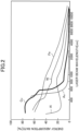
FIG. 2 is a graph showing a relationship between the wavelength of laser light at 300 K and the energy absorption rates of various metals including copper. -
FIG. 3 is a plan view showing the positions of beams of first and second laser lights (L1, L2). -
FIG. 4 is a plan view showing a variation of the positions of beams of the first and second laser lights (L1, L2). -
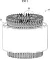
FIG. 5 is a perspective view of an electric rotating machine (30). -
FIG. 6 is a perspective view showing a laser welding method for laser-welding end portions of a plurality of conductor segments (32) of the electric rotating machine (30). -
FIG. 7 is a perspective view showing the welded end portions of the plurality of conductor segments (32) of the electric rotating machine (30). -
FIG. 8 is a perspective view showing a variation of the laser welding method for laser-welding the end portions of the plurality of conductor segments (32) of the electric rotating machine (30). -
FIG. 9 is a front view of the welded end portions of the conductor segments (32). -
FIG. 10 is a perspective view showing a method for irradiating the end portions of the conductor segments (32) with the first and second laser lights (L1, L2). -
FIG. 11 is a perspective view showing a variation of the method for irradiating the end portions of the conductor segments (32) with the first and second laser lights (L1, L2). - In the following, an embodiment will be described in detail.
- In a laser welding method according to the embodiment, a material (10) containing copper as a main component is irradiated with laser light, and is welded to a bonding target metal material (20). In this case, as shown in
FIG. 1 , a surface of the material (10) is heated by irradiation with a first laser light (L1), and is welded to the bonding target metal material (20) by irradiation of the heated surface of the portion, which has been irradiated with the first laser light (L1), of the material (10) with a second laser light (L2) with which the energy absorption rate of copper contained in the material (10) increases by an increase in the temperature of the material (10). - In the laser welding method according to this embodiment, the material (10) containing copper as the main component is heated by irradiation with the first laser light (L 1). In addition, the portion of the material (10) irradiated with the first laser light (L1) is irradiated with the second laser light (L2). With the second laser light (L2), the energy absorption rate of copper contained in the material (10) increases by an increase in the temperature of the material (10). Thus, when the portion heated and temperature-increased by irradiation with the first laser light (L1) is irradiated with the second laser light (L2), the second laser light (L2) is absorbed by copper contained in the material (10) at a high energy absorption rate, and the high energy density is applied to the material (10). Accordingly, the material (10) is melted, and can be welded to the bonding target metal material (20). Thus, the material (10) containing copper as the main component can be welded to the bonding target metal material (20) by use of a combination of the first and second laser lights (L1, L2).
- For example, as shown in
FIG. 2 , for a laser light having a wavelength band of around 500 nm, the energy absorption rate of copper is high, but it is difficult to obtain a level of high energy density which can be used for welding. On the other hand, a laser light having a wavelength band of around 1000 nm can provide high energy density suitable for welding, but the energy absorption rate of copper is low for such a laser light. Here, copper has such properties that when the temperature increases, the energy absorption rate for the laser light having a wavelength band of around 1000 nm increases. Accordingly, the former can be suitably used as the first laser light (L1), and the latter can be suitably used as the second laser light (L2). - Here, the material (10) containing copper as the main component may be either pure copper or a copper alloy containing 50 mass% or more of copper. The bonding target metal material (20) may be made of the same metal as in the material (10), which contains copper as a main component, or may be made of a different type of metal.
- The wavelength of the first laser light (L1) is preferably 584 nm or less for efficiently increasing the temperature of the material (10), and is more preferably 470 nm, at which the energy absorption rate of copper is high, for stably increasing the temperature of the material (10). The wavelength of the first laser light (L1) is preferably 400 nm or more for a practical perspective. The first laser light (L1) may be a single-wavelength laser light, or may be laser light with a plurality of different wavelengths superimposed.
- The energy absorption rate of copper contained in the material (10) for the first laser light (L1) at 300 K is preferably 60% or more, more preferably 80% or more for efficiently increasing the temperature of the material (10).
- The power density of the first laser light (L1) is preferably 125000 W/cm2 or more, more preferably 500000 W/cm2 or more, and preferably 5100000 W/cm2 or less for efficiently increasing the temperature of the material (10).
- A light source of the first laser light (L1) is preferably a diode laser, more preferably one having an oscillation wavelength band of 400 nm or more to 470 nm or less as described above.
- The temperature of the material (10) heated by irradiation with the first laser light (L1) is preferably 200°C or more, more preferably 400°C or more, and preferably 1083°C or less for increasing the energy absorption rate for the second laser light (L2).
- The wavelength of the second laser light (L2) is preferably 800 nm or more, more preferably 1030 nm or more, and preferably 1500 nm or less for efficiently bringing the material (10) into a weldable molten state. The wavelength of the second laser light (L2) is preferably 1200 nm or less for a practical perspective The second laser light (L2) may be a single-wavelength laser light, or may be laser light with a plurality of different wavelengths superimposed.
- The energy absorption rate of copper contained in the material (10) for the second laser light (L2) after the temperature has increased is preferably 30% or more, more preferably 60% or more for bringing the heated material (10) into the weldable molten state. The energy absorption rate of copper contained in the material (10) for the second laser light (L2) at 300 K before the temperature increases is, for example, 0.9% or more to 8.0% or less.
- The power density of the second laser light (L2) is preferably 6250000 W/cm2 or more, more preferably 20000000 W/cm2 or more, and preferably 200000000 W/cm2 or less for efficiently bringing the material (10) into the weldable molten state.
- A light source of the second laser light (L2) is preferably an infrared laser.
- Irradiation of the material (10) with the first and second laser lights (L1, L2) is preferably performed such that the second laser light (L2) is contained in the first laser light (L1), as shown in
FIGS. 3 to 5 . The number of beams of the second laser light (L2) is one or more for one first laser light (L1), and as shown inFIG. 3 , is at least one for one first laser light (L1). However, if there are two or more beams of the second laser light (L2) for one beam of the first laser light (L1) as shown inFIG. 4 , the material (10) can be more uniformly melted. - Next, a method of manufacturing an electric rotating machine (30) such as an electric motor or an electric generator by the laser welding method according to the embodiment will be described.
- As shown in
FIG. 5 , in the electric rotating machine (30), a plurality of conductor segments (32) is respectively inserted into a plurality of slots (not shown) formed at a stator core (31), and end portions of the plurality of conductor segments (32) inserted into the slots are made of the material (10) containing copper as the main component. Then, in such manufacturing, each of the end portions of the plurality of conductor segments (32) is spot-irradiated with the first and second laser lights (L1, L2) by the laser welding method according to the embodiment, as shown inFIG. 6 . Accordingly, the end portions of the plurality of conductor segments (32) are welded to each other as shown inFIG. 7 . In this case, the end portions of the plurality of conductor segments (32) may be irradiated with the first and second laser lights (L1, L2) such that the first and second laser lights (L1, L2) are swept thereon, as shown inFIG. 8 . - As described above, the first and second laser lights (L1, L2) are combined using the laser welding method according to the embodiment so that the end portions of the conductor segments (32) made of the material (10) containing copper as the main component can be welded to each other. In this case, since the first laser light (L1) having a low energy density and the second laser light (L2) having a high energy density are superimposed on each other, a thermally-conductive welding portion (33) welded so as to be bridged between end surfaces of the conductor segments (32) and a keyhole-shaped welding portion (34) welded by Infiltration of the material (10) into between the end portions of the conductor segments (32) are formed between the end portions of the conductor segments (32) as shown in
FIG. 9 . Thus, a high welding strength can be obtained. - Since high energy density is applied to the conductor segment (32), it is not necessary to increase the length of an exposed conductor portion extending to the end portion of the conductor segment (32), and therefore, a coil end portion can be reduced in size. Further, since high-speed welding among the end portions of the conductor segments (32) can be performed, a high production capacity can be obtained. Moreover, since additional equipment for obtaining a high production capacity is not necessary, reduction in an equipment investment can be achieved.
- In manufacturing of the electric rotating machine (30), each of the end portions of the plurality of conductor segments (32) is irradiated with one or more pairs of first and second laser lights (L1, L2). Each of the end portions of the plurality of conductor segments (32) is irradiated with at least one pair of first and second laser lights (L1, L2), as shown in
FIG. 10 . When each end portion is irradiated with two or more pairs of first and second laser lights (L1, L2) as shown inFIG. 11 , variation in welding among the end portions of the conductor segments (32) can be reduced. - The present invention is useful for a laser welding method and a technical field using the laser welding method.
-
- L1
- First Laser Light
- L2
- Second Laser Light
- 10
- Material
- 30
- Electric Rotating Machine
- 31
- Stator Core
- 32
- Conductor Segment
Claims (10)
- A laser welding method for welding a material (10) containing copper as a main component, the laser welding method comprising:
heating the material (10) by irradiation with a first laser light (L1) and welding the material (10) by irradiation of a portion, which has been irradiated with the first laser light (L1), of the material (10) with a second laser light (L2) with which an energy absorption rate of the copper contained in the material (10) increases by an increase in a temperature of the material (10). - The laser welding method of claim 1, wherein
a wavelength of the first laser light (L1) is 584 nm or less. - The laser welding method of claim 2, wherein
the wavelength of the first laser light (L1) is 470 nm or less. - The laser welding method of any one of claims 1 to 3, wherein
a light source of the first laser light (L1) is a diode laser. - The laser welding method of any one of claims 1 to 4, wherein
a wavelength of the second laser light (L2) is 800 nm or more. - The laser welding method of any one of claims 1 to 5, wherein
a light source of the second laser light (L2) is an infrared laser. - The laser welding method of any one of claims 1 to 6, wherein
the number of beams of the second laser light (L2) is one or more for one beam of the first laser light (L1). - The laser welding method of any one of claims 1 to 7, wherein
the material (10) is irradiated with two or more pairs of first and second laser lights (L1, L2). - A method for manufacturing an electric rotating machine (30) in which a plurality of conductor segments (32) is respectively inserted into a plurality of slots formed at a stator core (31) and end portions of the plurality of conductor segments (32) inserted into the slots are made of a material (10) containing copper as a main component, the method comprising:
welding the end portions of the plurality of conductor segments (32) by the laser welding method of any one of claims 1 to 8. - The method of claim 9, wherein
each of the end portions of the plurality of conductor segments (32) is irradiated with one or more pairs of first and second laser lights (L1, L2).
Applications Claiming Priority (2)
| Application Number | Priority Date | Filing Date | Title |
|---|---|---|---|
| JP2020079962A JP7016114B2 (en) | 2020-04-30 | 2020-04-30 | Laser welding method and manufacturing method of rotary electric machine using it |
| PCT/JP2021/011791 WO2021220666A1 (en) | 2020-04-30 | 2021-03-22 | Laser welding method and method for manufacturing electric rotating machine using same |
Publications (4)
| Publication Number | Publication Date |
|---|---|
| EP4129558A1 true EP4129558A1 (en) | 2023-02-08 |
| EP4129558A4 EP4129558A4 (en) | 2023-10-11 |
| EP4129558C0 EP4129558C0 (en) | 2024-10-30 |
| EP4129558B1 EP4129558B1 (en) | 2024-10-30 |
Family
ID=78281066
Family Applications (1)
| Application Number | Title | Priority Date | Filing Date |
|---|---|---|---|
| EP21795705.9A Active EP4129558B1 (en) | 2020-04-30 | 2021-03-22 | Laser welding method and manufacturing method of electric rotating machine by the laser welding method |
Country Status (5)
| Country | Link |
|---|---|
| US (1) | US20230050577A1 (en) |
| EP (1) | EP4129558B1 (en) |
| JP (2) | JP7016114B2 (en) |
| CN (1) | CN115427186B (en) |
| WO (1) | WO2021220666A1 (en) |
Families Citing this family (5)
| Publication number | Priority date | Publication date | Assignee | Title |
|---|---|---|---|---|
| JPWO2023135859A1 (en) * | 2022-01-14 | 2023-07-20 | ||
| JP7847348B2 (en) * | 2022-02-02 | 2026-04-17 | パナソニックIpマネジメント株式会社 | Laser processing method |
| JP2024108201A (en) | 2023-01-31 | 2024-08-13 | 古河電気工業株式会社 | Laser welding apparatus and laser welding method |
| JP2024108200A (en) | 2023-01-31 | 2024-08-13 | 古河電気工業株式会社 | Laser welding apparatus and laser welding method |
| JP7847190B1 (en) * | 2024-10-23 | 2026-04-16 | 株式会社アマダ | Laser welding machine and laser welding method |
Family Cites Families (14)
| Publication number | Priority date | Publication date | Assignee | Title |
|---|---|---|---|---|
| JPH05104276A (en) * | 1991-10-16 | 1993-04-27 | Toshiba Corp | Laser processing apparatus and laser processing method |
| JP2001196665A (en) * | 2000-01-13 | 2001-07-19 | Hamamatsu Kagaku Gijutsu Kenkyu Shinkokai | Two-wavelength laser processing optical device and laser processing method |
| JP2002316282A (en) * | 2001-04-18 | 2002-10-29 | Matsushita Electric Ind Co Ltd | Laser processing method and apparatus |
| JP2005313195A (en) * | 2004-04-28 | 2005-11-10 | Miyachi Technos Corp | Dual wavelength superposition type laser emission unit and laser processing apparatus |
| JP2006066794A (en) * | 2004-08-30 | 2006-03-09 | Miyachi Technos Corp | Wire bonding method |
| JP2008246502A (en) | 2007-03-29 | 2008-10-16 | Tokyu Car Corp | Laser welding method |
| JP2009269036A (en) | 2008-04-30 | 2009-11-19 | Tokyu Car Corp | Laser welding method |
| CN102500919A (en) * | 2011-10-12 | 2012-06-20 | 深圳市联赢激光股份有限公司 | Dual-laser beam hybrid welding device and hybrid welding method |
| JP5805138B2 (en) * | 2013-05-17 | 2015-11-04 | 本田技研工業株式会社 | Manufacturing method of rotating electrical machine |
| JP2017098161A (en) * | 2015-11-26 | 2017-06-01 | トヨタ自動車株式会社 | Joining method of flat wire |
| CN107598371A (en) * | 2017-09-21 | 2018-01-19 | 中国科学院长春光学精密机械与物理研究所 | A kind of welding method of coppersmith part |
| JP2019118159A (en) * | 2017-12-26 | 2019-07-18 | トヨタ自動車株式会社 | Welding method for segment conductor |
| JP7166109B2 (en) * | 2018-09-03 | 2022-11-07 | 三菱電機株式会社 | Rotating electric machine stator |
| CN109926719B (en) * | 2019-04-18 | 2020-06-23 | 武汉锐科光纤激光技术股份有限公司 | Method and device for welding copper and copper alloy materials |
-
2020
- 2020-04-30 JP JP2020079962A patent/JP7016114B2/en active Active
-
2021
- 2021-03-22 CN CN202180029031.8A patent/CN115427186B/en active Active
- 2021-03-22 EP EP21795705.9A patent/EP4129558B1/en active Active
- 2021-03-22 WO PCT/JP2021/011791 patent/WO2021220666A1/en not_active Ceased
-
2022
- 2022-01-17 JP JP2022004876A patent/JP7408102B2/en active Active
- 2022-10-28 US US17/976,518 patent/US20230050577A1/en active Pending
Also Published As
| Publication number | Publication date |
|---|---|
| US20230050577A1 (en) | 2023-02-16 |
| EP4129558C0 (en) | 2024-10-30 |
| JP2021171809A (en) | 2021-11-01 |
| EP4129558B1 (en) | 2024-10-30 |
| JP7408102B2 (en) | 2024-01-05 |
| CN115427186B (en) | 2023-09-15 |
| JP2022036296A (en) | 2022-03-04 |
| CN115427186A (en) | 2022-12-02 |
| EP4129558A4 (en) | 2023-10-11 |
| WO2021220666A1 (en) | 2021-11-04 |
| JP7016114B2 (en) | 2022-02-04 |
Similar Documents
| Publication | Publication Date | Title |
|---|---|---|
| EP4129558B1 (en) | Laser welding method and manufacturing method of electric rotating machine by the laser welding method | |
| JP5958109B2 (en) | Conductor joining method for rotating electrical machine | |
| KR20230090371A (en) | Visible laser welding of electronic packaging, automotive electrics, battery and other components | |
| EP4268358B1 (en) | Method and device for laser welding conductor wires | |
| CN113453836A (en) | Method for joining copper hairpins and stator | |
| US12508669B2 (en) | Method for welding copper-including members, and method for manufacturing electrical rotating machine | |
| EP4238684B1 (en) | Welding method and laser device | |
| CN113967787A (en) | Laser welding method | |
| JP2014007794A (en) | Method for bonding conductor of rotary electric machine and coil of rotary electric machine | |
| JP7335419B2 (en) | Stator manufacturing method for rotary electric machine | |
| JP7360480B2 (en) | Stator manufacturing method | |
| JP2022182279A (en) | Laser welding method, laser welding device, and electric apparatus | |
| CN113275745A (en) | Composite laser equipment | |
| KR102916164B1 (en) | Method for laser welding of bent metal-containing rod conductors with strength redistribution in the initial and final stages, corresponding rod conductor assemblies and use of such rod conductor assemblies | |
| CN102574242B (en) | Systems and methods utilizing fiber lasers for titanium welding using argon blanket gas | |
| JP7478697B2 (en) | Manufacturing method of a stator for a rotating electric machine | |
| CN118510177A (en) | Special-shaped bonding pad welding method and electronic product | |
| WO2024080097A1 (en) | Rotating electric machine stator manufacturing method and rotating electric machine stator manufacturing device | |
| CN113878231A (en) | Laser welding method for flat copper wire of motor coil | |
| CN103779071A (en) | Manufacturing method for winding-type coil component | |
| WO1997004507A1 (en) | Method of laser welding litz wire | |
| WO2019167454A1 (en) | Joint structural body and method for manufacturing same | |
| JP2025025438A (en) | Method for joining copper wire | |
| CN121440317A (en) | Vehicles with welded busbar connectors |
Legal Events
| Date | Code | Title | Description |
|---|---|---|---|
| STAA | Information on the status of an ep patent application or granted ep patent |
Free format text: STATUS: THE INTERNATIONAL PUBLICATION HAS BEEN MADE |
|
| PUAI | Public reference made under article 153(3) epc to a published international application that has entered the european phase |
Free format text: ORIGINAL CODE: 0009012 |
|
| STAA | Information on the status of an ep patent application or granted ep patent |
Free format text: STATUS: REQUEST FOR EXAMINATION WAS MADE |
|
| 17P | Request for examination filed |
Effective date: 20221026 |
|
| AK | Designated contracting states |
Kind code of ref document: A1 Designated state(s): AL AT BE BG CH CY CZ DE DK EE ES FI FR GB GR HR HU IE IS IT LI LT LU LV MC MK MT NL NO PL PT RO RS SE SI SK SM TR |
|
| P01 | Opt-out of the competence of the unified patent court (upc) registered |
Effective date: 20230525 |
|
| DAV | Request for validation of the european patent (deleted) | ||
| DAX | Request for extension of the european patent (deleted) | ||
| A4 | Supplementary search report drawn up and despatched |
Effective date: 20230907 |
|
| RIC1 | Information provided on ipc code assigned before grant |
Ipc: B23K 103/18 20060101ALN20230901BHEP Ipc: B23K 103/12 20060101ALN20230901BHEP Ipc: B23K 101/38 20060101ALN20230901BHEP Ipc: B23K 101/36 20060101ALN20230901BHEP Ipc: H02K 15/00 20060101ALI20230901BHEP Ipc: B23K 26/323 20140101ALI20230901BHEP Ipc: B23K 26/06 20140101ALI20230901BHEP Ipc: B23K 26/244 20140101ALI20230901BHEP Ipc: B23K 26/60 20140101ALI20230901BHEP Ipc: H02K 15/04 20060101ALI20230901BHEP Ipc: B23K 26/22 20060101ALI20230901BHEP Ipc: B23K 26/32 20140101AFI20230901BHEP |
|
| GRAP | Despatch of communication of intention to grant a patent |
Free format text: ORIGINAL CODE: EPIDOSNIGR1 |
|
| STAA | Information on the status of an ep patent application or granted ep patent |
Free format text: STATUS: GRANT OF PATENT IS INTENDED |
|
| RIC1 | Information provided on ipc code assigned before grant |
Ipc: B23K 103/18 20060101ALN20240506BHEP Ipc: B23K 103/12 20060101ALN20240506BHEP Ipc: B23K 101/38 20060101ALN20240506BHEP Ipc: B23K 101/36 20060101ALN20240506BHEP Ipc: H02K 15/00 20060101ALI20240506BHEP Ipc: B23K 26/323 20140101ALI20240506BHEP Ipc: B23K 26/06 20140101ALI20240506BHEP Ipc: B23K 26/244 20140101ALI20240506BHEP Ipc: B23K 26/60 20140101ALI20240506BHEP Ipc: H02K 15/04 20060101ALI20240506BHEP Ipc: B23K 26/22 20060101ALI20240506BHEP Ipc: B23K 26/32 20140101AFI20240506BHEP |
|
| RIC1 | Information provided on ipc code assigned before grant |
Ipc: B23K 103/18 20060101ALN20240517BHEP Ipc: B23K 103/12 20060101ALN20240517BHEP Ipc: B23K 101/38 20060101ALN20240517BHEP Ipc: B23K 101/36 20060101ALN20240517BHEP Ipc: H02K 15/00 20060101ALI20240517BHEP Ipc: B23K 26/323 20140101ALI20240517BHEP Ipc: B23K 26/06 20140101ALI20240517BHEP Ipc: B23K 26/244 20140101ALI20240517BHEP Ipc: B23K 26/60 20140101ALI20240517BHEP Ipc: H02K 15/04 20060101ALI20240517BHEP Ipc: B23K 26/22 20060101ALI20240517BHEP Ipc: B23K 26/32 20140101AFI20240517BHEP |
|
| INTG | Intention to grant announced |
Effective date: 20240610 |
|
| GRAS | Grant fee paid |
Free format text: ORIGINAL CODE: EPIDOSNIGR3 |
|
| GRAA | (expected) grant |
Free format text: ORIGINAL CODE: 0009210 |
|
| STAA | Information on the status of an ep patent application or granted ep patent |
Free format text: STATUS: THE PATENT HAS BEEN GRANTED |
|
| AK | Designated contracting states |
Kind code of ref document: B1 Designated state(s): AL AT BE BG CH CY CZ DE DK EE ES FI FR GB GR HR HU IE IS IT LI LT LU LV MC MK MT NL NO PL PT RO RS SE SI SK SM TR |
|
| REG | Reference to a national code |
Ref country code: GB Ref legal event code: FG4D |
|
| REG | Reference to a national code |
Ref country code: CH Ref legal event code: EP |
|
| REG | Reference to a national code |
Ref country code: DE Ref legal event code: R096 Ref document number: 602021021114 Country of ref document: DE |
|
| REG | Reference to a national code |
Ref country code: IE Ref legal event code: FG4D |
|
| U01 | Request for unitary effect filed |
Effective date: 20241030 |
|
| U07 | Unitary effect registered |
Designated state(s): AT BE BG DE DK EE FI FR IT LT LU LV MT NL PT RO SE SI Effective date: 20241106 |
|
| P04 | Withdrawal of opt-out of the competence of the unified patent court (upc) registered |
Free format text: CASE NUMBER: APP_59477/2024 Effective date: 20241101 |
|
| U20 | Renewal fee for the european patent with unitary effect paid |
Year of fee payment: 5 Effective date: 20250205 |
|
| PG25 | Lapsed in a contracting state [announced via postgrant information from national office to epo] |
Ref country code: HR Free format text: LAPSE BECAUSE OF FAILURE TO SUBMIT A TRANSLATION OF THE DESCRIPTION OR TO PAY THE FEE WITHIN THE PRESCRIBED TIME-LIMIT Effective date: 20241030 Ref country code: IS Free format text: LAPSE BECAUSE OF FAILURE TO SUBMIT A TRANSLATION OF THE DESCRIPTION OR TO PAY THE FEE WITHIN THE PRESCRIBED TIME-LIMIT Effective date: 20250228 |
|
| PG25 | Lapsed in a contracting state [announced via postgrant information from national office to epo] |
Ref country code: ES Free format text: LAPSE BECAUSE OF FAILURE TO SUBMIT A TRANSLATION OF THE DESCRIPTION OR TO PAY THE FEE WITHIN THE PRESCRIBED TIME-LIMIT Effective date: 20241030 |
|
| PG25 | Lapsed in a contracting state [announced via postgrant information from national office to epo] |
Ref country code: NO Free format text: LAPSE BECAUSE OF FAILURE TO SUBMIT A TRANSLATION OF THE DESCRIPTION OR TO PAY THE FEE WITHIN THE PRESCRIBED TIME-LIMIT Effective date: 20250130 |
|
| PG25 | Lapsed in a contracting state [announced via postgrant information from national office to epo] |
Ref country code: GR Free format text: LAPSE BECAUSE OF FAILURE TO SUBMIT A TRANSLATION OF THE DESCRIPTION OR TO PAY THE FEE WITHIN THE PRESCRIBED TIME-LIMIT Effective date: 20250131 |
|
| PG25 | Lapsed in a contracting state [announced via postgrant information from national office to epo] |
Ref country code: PL Free format text: LAPSE BECAUSE OF FAILURE TO SUBMIT A TRANSLATION OF THE DESCRIPTION OR TO PAY THE FEE WITHIN THE PRESCRIBED TIME-LIMIT Effective date: 20241030 |
|
| PG25 | Lapsed in a contracting state [announced via postgrant information from national office to epo] |
Ref country code: RS Free format text: LAPSE BECAUSE OF FAILURE TO SUBMIT A TRANSLATION OF THE DESCRIPTION OR TO PAY THE FEE WITHIN THE PRESCRIBED TIME-LIMIT Effective date: 20250130 |
|
| PG25 | Lapsed in a contracting state [announced via postgrant information from national office to epo] |
Ref country code: SM Free format text: LAPSE BECAUSE OF FAILURE TO SUBMIT A TRANSLATION OF THE DESCRIPTION OR TO PAY THE FEE WITHIN THE PRESCRIBED TIME-LIMIT Effective date: 20241030 |
|
| PG25 | Lapsed in a contracting state [announced via postgrant information from national office to epo] |
Ref country code: SK Free format text: LAPSE BECAUSE OF FAILURE TO SUBMIT A TRANSLATION OF THE DESCRIPTION OR TO PAY THE FEE WITHIN THE PRESCRIBED TIME-LIMIT Effective date: 20241030 |
|
| PG25 | Lapsed in a contracting state [announced via postgrant information from national office to epo] |
Ref country code: CZ Free format text: LAPSE BECAUSE OF FAILURE TO SUBMIT A TRANSLATION OF THE DESCRIPTION OR TO PAY THE FEE WITHIN THE PRESCRIBED TIME-LIMIT Effective date: 20241030 |
|
| PLBE | No opposition filed within time limit |
Free format text: ORIGINAL CODE: 0009261 |
|
| STAA | Information on the status of an ep patent application or granted ep patent |
Free format text: STATUS: NO OPPOSITION FILED WITHIN TIME LIMIT |
|
| 26N | No opposition filed |
Effective date: 20250731 |
|
| PG25 | Lapsed in a contracting state [announced via postgrant information from national office to epo] |
Ref country code: MC Free format text: LAPSE BECAUSE OF FAILURE TO SUBMIT A TRANSLATION OF THE DESCRIPTION OR TO PAY THE FEE WITHIN THE PRESCRIBED TIME-LIMIT Effective date: 20241030 |
|
| REG | Reference to a national code |
Ref country code: CH Ref legal event code: H13 Free format text: ST27 STATUS EVENT CODE: U-0-0-H10-H13 (AS PROVIDED BY THE NATIONAL OFFICE) Effective date: 20251023 |
|
| PG25 | Lapsed in a contracting state [announced via postgrant information from national office to epo] |
Ref country code: CH Free format text: LAPSE BECAUSE OF NON-PAYMENT OF DUE FEES Effective date: 20250331 |
|
| PG25 | Lapsed in a contracting state [announced via postgrant information from national office to epo] |
Ref country code: IE Free format text: LAPSE BECAUSE OF NON-PAYMENT OF DUE FEES Effective date: 20250322 |
|
| U20 | Renewal fee for the european patent with unitary effect paid |
Year of fee payment: 6 Effective date: 20260209 |
|
| PGFP | Annual fee paid to national office [announced via postgrant information from national office to epo] |
Ref country code: GB Payment date: 20260209 Year of fee payment: 6 |
|
| PG25 | Lapsed in a contracting state [announced via postgrant information from national office to epo] |
Ref country code: CY Free format text: LAPSE BECAUSE OF FAILURE TO SUBMIT A TRANSLATION OF THE DESCRIPTION OR TO PAY THE FEE WITHIN THE PRESCRIBED TIME-LIMIT Effective date: 20241030 |
|
| PG25 | Lapsed in a contracting state [announced via postgrant information from national office to epo] |
Ref country code: TR Free format text: LAPSE BECAUSE OF FAILURE TO SUBMIT A TRANSLATION OF THE DESCRIPTION OR TO PAY THE FEE WITHIN THE PRESCRIBED TIME-LIMIT Effective date: 20241030 |