EP4129389A1 - Catheter - Google Patents
Catheter Download PDFInfo
- Publication number
- EP4129389A1 EP4129389A1 EP21780833.6A EP21780833A EP4129389A1 EP 4129389 A1 EP4129389 A1 EP 4129389A1 EP 21780833 A EP21780833 A EP 21780833A EP 4129389 A1 EP4129389 A1 EP 4129389A1
- Authority
- EP
- European Patent Office
- Prior art keywords
- tubular portion
- opening
- catheter
- fluid
- extension
- Prior art date
- Legal status (The legal status is an assumption and is not a legal conclusion. Google has not performed a legal analysis and makes no representation as to the accuracy of the status listed.)
- Withdrawn
Links
- 239000012530 fluid Substances 0.000 claims abstract description 152
- 210000001835 viscera Anatomy 0.000 description 50
- 210000003238 esophagus Anatomy 0.000 description 45
- 239000000463 material Substances 0.000 description 16
- 238000013153 catheter ablation Methods 0.000 description 15
- 230000037361 pathway Effects 0.000 description 10
- 238000002679 ablation Methods 0.000 description 5
- 238000001816 cooling Methods 0.000 description 5
- 238000004519 manufacturing process Methods 0.000 description 5
- 239000004952 Polyamide Substances 0.000 description 4
- 238000009529 body temperature measurement Methods 0.000 description 4
- 229920002647 polyamide Polymers 0.000 description 4
- 230000000694 effects Effects 0.000 description 3
- 238000010438 heat treatment Methods 0.000 description 3
- 238000012986 modification Methods 0.000 description 3
- 230000004048 modification Effects 0.000 description 3
- 210000003800 pharynx Anatomy 0.000 description 3
- XEEYBQQBJWHFJM-UHFFFAOYSA-N Iron Chemical compound [Fe] XEEYBQQBJWHFJM-UHFFFAOYSA-N 0.000 description 2
- 239000004677 Nylon Substances 0.000 description 2
- 229920002614 Polyether block amide Polymers 0.000 description 2
- 239000004721 Polyphenylene oxide Substances 0.000 description 2
- 229910052751 metal Inorganic materials 0.000 description 2
- 239000002184 metal Substances 0.000 description 2
- 210000003928 nasal cavity Anatomy 0.000 description 2
- 229920001778 nylon Polymers 0.000 description 2
- 230000002093 peripheral effect Effects 0.000 description 2
- 229920000570 polyether Polymers 0.000 description 2
- 229920000098 polyolefin Polymers 0.000 description 2
- 229920001296 polysiloxane Polymers 0.000 description 2
- 229920002635 polyurethane Polymers 0.000 description 2
- 239000004814 polyurethane Substances 0.000 description 2
- 239000004800 polyvinyl chloride Substances 0.000 description 2
- 229920000915 polyvinyl chloride Polymers 0.000 description 2
- 229910000838 Al alloy Inorganic materials 0.000 description 1
- 206010003658 Atrial Fibrillation Diseases 0.000 description 1
- 229910001006 Constantan Inorganic materials 0.000 description 1
- RYGMFSIKBFXOCR-UHFFFAOYSA-N Copper Chemical compound [Cu] RYGMFSIKBFXOCR-UHFFFAOYSA-N 0.000 description 1
- 229910000640 Fe alloy Inorganic materials 0.000 description 1
- WQZGKKKJIJFFOK-GASJEMHNSA-N Glucose Natural products OC[C@H]1OC(O)[C@H](O)[C@@H](O)[C@@H]1O WQZGKKKJIJFFOK-GASJEMHNSA-N 0.000 description 1
- 229910001260 Pt alloy Inorganic materials 0.000 description 1
- FAPWRFPIFSIZLT-UHFFFAOYSA-M Sodium chloride Chemical compound [Na+].[Cl-] FAPWRFPIFSIZLT-UHFFFAOYSA-M 0.000 description 1
- XAGFODPZIPBFFR-UHFFFAOYSA-N aluminium Chemical compound [Al] XAGFODPZIPBFFR-UHFFFAOYSA-N 0.000 description 1
- 206010003119 arrhythmia Diseases 0.000 description 1
- 230000006793 arrhythmia Effects 0.000 description 1
- WQZGKKKJIJFFOK-VFUOTHLCSA-N beta-D-glucose Chemical compound OC[C@H]1O[C@@H](O)[C@H](O)[C@@H](O)[C@@H]1O WQZGKKKJIJFFOK-VFUOTHLCSA-N 0.000 description 1
- 210000002318 cardia Anatomy 0.000 description 1
- 238000009548 contrast radiography Methods 0.000 description 1
- 239000008121 dextrose Substances 0.000 description 1
- 238000001727 in vivo Methods 0.000 description 1
- 238000002347 injection Methods 0.000 description 1
- 239000007924 injection Substances 0.000 description 1
- 238000003780 insertion Methods 0.000 description 1
- 230000037431 insertion Effects 0.000 description 1
- 239000007769 metal material Substances 0.000 description 1
- 229910001000 nickel titanium Inorganic materials 0.000 description 1
- 210000001331 nose Anatomy 0.000 description 1
- 239000008213 purified water Substances 0.000 description 1
- 229910001285 shape-memory alloy Inorganic materials 0.000 description 1
- 239000011780 sodium chloride Substances 0.000 description 1
- 238000005476 soldering Methods 0.000 description 1
- 239000000243 solution Substances 0.000 description 1
- 239000010935 stainless steel Substances 0.000 description 1
- 229910001256 stainless steel alloy Inorganic materials 0.000 description 1
- 210000002784 stomach Anatomy 0.000 description 1
- 238000006467 substitution reaction Methods 0.000 description 1
- 239000008399 tap water Substances 0.000 description 1
- 235000020679 tap water Nutrition 0.000 description 1
- 239000012815 thermoplastic material Substances 0.000 description 1
- 210000003437 trachea Anatomy 0.000 description 1
- XLYOFNOQVPJJNP-UHFFFAOYSA-N water Chemical compound O XLYOFNOQVPJJNP-UHFFFAOYSA-N 0.000 description 1
Images




Classifications
-
- A—HUMAN NECESSITIES
- A61—MEDICAL OR VETERINARY SCIENCE; HYGIENE
- A61F—FILTERS IMPLANTABLE INTO BLOOD VESSELS; PROSTHESES; DEVICES PROVIDING PATENCY TO, OR PREVENTING COLLAPSING OF, TUBULAR STRUCTURES OF THE BODY, e.g. STENTS; ORTHOPAEDIC, NURSING OR CONTRACEPTIVE DEVICES; FOMENTATION; TREATMENT OR PROTECTION OF EYES OR EARS; BANDAGES, DRESSINGS OR ABSORBENT PADS; FIRST-AID KITS
- A61F7/00—Heating or cooling appliances for medical or therapeutic treatment of the human body
- A61F7/12—Devices for heating or cooling internal body cavities
-
- A—HUMAN NECESSITIES
- A61—MEDICAL OR VETERINARY SCIENCE; HYGIENE
- A61B—DIAGNOSIS; SURGERY; IDENTIFICATION
- A61B18/00—Surgical instruments, devices or methods for transferring non-mechanical forms of energy to or from the body
- A61B18/04—Surgical instruments, devices or methods for transferring non-mechanical forms of energy to or from the body by heating
- A61B18/12—Surgical instruments, devices or methods for transferring non-mechanical forms of energy to or from the body by heating by passing a current through the tissue to be heated, e.g. high-frequency current
- A61B18/14—Probes or electrodes therefor
- A61B18/1492—Probes or electrodes therefor having a flexible, catheter-like structure, e.g. for heart ablation
-
- A—HUMAN NECESSITIES
- A61—MEDICAL OR VETERINARY SCIENCE; HYGIENE
- A61B—DIAGNOSIS; SURGERY; IDENTIFICATION
- A61B18/00—Surgical instruments, devices or methods for transferring non-mechanical forms of energy to or from the body
-
- A—HUMAN NECESSITIES
- A61—MEDICAL OR VETERINARY SCIENCE; HYGIENE
- A61M—DEVICES FOR INTRODUCING MEDIA INTO, OR ONTO, THE BODY; DEVICES FOR TRANSDUCING BODY MEDIA OR FOR TAKING MEDIA FROM THE BODY; DEVICES FOR PRODUCING OR ENDING SLEEP OR STUPOR
- A61M25/00—Catheters; Hollow probes
- A61M25/0021—Catheters; Hollow probes characterised by the form of the tubing
- A61M25/0023—Catheters; Hollow probes characterised by the form of the tubing by the form of the lumen, e.g. cross-section, variable diameter
- A61M25/0026—Multi-lumen catheters with stationary elements
-
- A—HUMAN NECESSITIES
- A61—MEDICAL OR VETERINARY SCIENCE; HYGIENE
- A61M—DEVICES FOR INTRODUCING MEDIA INTO, OR ONTO, THE BODY; DEVICES FOR TRANSDUCING BODY MEDIA OR FOR TAKING MEDIA FROM THE BODY; DEVICES FOR PRODUCING OR ENDING SLEEP OR STUPOR
- A61M25/00—Catheters; Hollow probes
- A61M25/0067—Catheters; Hollow probes characterised by the distal end, e.g. tips
- A61M25/0068—Static characteristics of the catheter tip, e.g. shape, atraumatic tip, curved tip or tip structure
- A61M25/007—Side holes, e.g. their profiles or arrangements; Provisions to keep side holes unblocked
-
- A—HUMAN NECESSITIES
- A61—MEDICAL OR VETERINARY SCIENCE; HYGIENE
- A61B—DIAGNOSIS; SURGERY; IDENTIFICATION
- A61B18/00—Surgical instruments, devices or methods for transferring non-mechanical forms of energy to or from the body
- A61B2018/00005—Cooling or heating of the probe or tissue immediately surrounding the probe
- A61B2018/00011—Cooling or heating of the probe or tissue immediately surrounding the probe with fluids
-
- A—HUMAN NECESSITIES
- A61—MEDICAL OR VETERINARY SCIENCE; HYGIENE
- A61B—DIAGNOSIS; SURGERY; IDENTIFICATION
- A61B18/00—Surgical instruments, devices or methods for transferring non-mechanical forms of energy to or from the body
- A61B2018/00005—Cooling or heating of the probe or tissue immediately surrounding the probe
- A61B2018/00011—Cooling or heating of the probe or tissue immediately surrounding the probe with fluids
- A61B2018/00029—Cooling or heating of the probe or tissue immediately surrounding the probe with fluids open
- A61B2018/00035—Cooling or heating of the probe or tissue immediately surrounding the probe with fluids open with return means
-
- A—HUMAN NECESSITIES
- A61—MEDICAL OR VETERINARY SCIENCE; HYGIENE
- A61B—DIAGNOSIS; SURGERY; IDENTIFICATION
- A61B18/00—Surgical instruments, devices or methods for transferring non-mechanical forms of energy to or from the body
- A61B2018/00053—Mechanical features of the instrument of device
- A61B2018/00166—Multiple lumina
-
- A—HUMAN NECESSITIES
- A61—MEDICAL OR VETERINARY SCIENCE; HYGIENE
- A61B—DIAGNOSIS; SURGERY; IDENTIFICATION
- A61B18/00—Surgical instruments, devices or methods for transferring non-mechanical forms of energy to or from the body
- A61B2018/00315—Surgical instruments, devices or methods for transferring non-mechanical forms of energy to or from the body for treatment of particular body parts
- A61B2018/00482—Digestive system
- A61B2018/00488—Esophagus
-
- A—HUMAN NECESSITIES
- A61—MEDICAL OR VETERINARY SCIENCE; HYGIENE
- A61B—DIAGNOSIS; SURGERY; IDENTIFICATION
- A61B18/00—Surgical instruments, devices or methods for transferring non-mechanical forms of energy to or from the body
- A61B2018/00571—Surgical instruments, devices or methods for transferring non-mechanical forms of energy to or from the body for achieving a particular surgical effect
- A61B2018/00577—Ablation
-
- A—HUMAN NECESSITIES
- A61—MEDICAL OR VETERINARY SCIENCE; HYGIENE
- A61B—DIAGNOSIS; SURGERY; IDENTIFICATION
- A61B18/00—Surgical instruments, devices or methods for transferring non-mechanical forms of energy to or from the body
- A61B2018/00636—Sensing and controlling the application of energy
- A61B2018/00696—Controlled or regulated parameters
- A61B2018/00744—Fluid flow
-
- A—HUMAN NECESSITIES
- A61—MEDICAL OR VETERINARY SCIENCE; HYGIENE
- A61B—DIAGNOSIS; SURGERY; IDENTIFICATION
- A61B18/00—Surgical instruments, devices or methods for transferring non-mechanical forms of energy to or from the body
- A61B2018/00636—Sensing and controlling the application of energy
- A61B2018/00773—Sensed parameters
- A61B2018/00791—Temperature
-
- A—HUMAN NECESSITIES
- A61—MEDICAL OR VETERINARY SCIENCE; HYGIENE
- A61B—DIAGNOSIS; SURGERY; IDENTIFICATION
- A61B18/00—Surgical instruments, devices or methods for transferring non-mechanical forms of energy to or from the body
- A61B2018/00636—Sensing and controlling the application of energy
- A61B2018/00773—Sensed parameters
- A61B2018/00791—Temperature
- A61B2018/00821—Temperature measured by a thermocouple
-
- A—HUMAN NECESSITIES
- A61—MEDICAL OR VETERINARY SCIENCE; HYGIENE
- A61B—DIAGNOSIS; SURGERY; IDENTIFICATION
- A61B2218/00—Details of surgical instruments, devices or methods for transferring non-mechanical forms of energy to or from the body
- A61B2218/001—Details of surgical instruments, devices or methods for transferring non-mechanical forms of energy to or from the body having means for irrigation and/or aspiration of substances to and/or from the surgical site
- A61B2218/002—Irrigation
-
- A—HUMAN NECESSITIES
- A61—MEDICAL OR VETERINARY SCIENCE; HYGIENE
- A61B—DIAGNOSIS; SURGERY; IDENTIFICATION
- A61B2218/00—Details of surgical instruments, devices or methods for transferring non-mechanical forms of energy to or from the body
- A61B2218/001—Details of surgical instruments, devices or methods for transferring non-mechanical forms of energy to or from the body having means for irrigation and/or aspiration of substances to and/or from the surgical site
- A61B2218/007—Aspiration
-
- A—HUMAN NECESSITIES
- A61—MEDICAL OR VETERINARY SCIENCE; HYGIENE
- A61B—DIAGNOSIS; SURGERY; IDENTIFICATION
- A61B2562/00—Details of sensors; Constructional details of sensor housings or probes; Accessories for sensors
- A61B2562/02—Details of sensors specially adapted for in-vivo measurements
- A61B2562/0271—Thermal or temperature sensors
-
- A—HUMAN NECESSITIES
- A61—MEDICAL OR VETERINARY SCIENCE; HYGIENE
- A61F—FILTERS IMPLANTABLE INTO BLOOD VESSELS; PROSTHESES; DEVICES PROVIDING PATENCY TO, OR PREVENTING COLLAPSING OF, TUBULAR STRUCTURES OF THE BODY, e.g. STENTS; ORTHOPAEDIC, NURSING OR CONTRACEPTIVE DEVICES; FOMENTATION; TREATMENT OR PROTECTION OF EYES OR EARS; BANDAGES, DRESSINGS OR ABSORBENT PADS; FIRST-AID KITS
- A61F7/00—Heating or cooling appliances for medical or therapeutic treatment of the human body
- A61F2007/0059—Heating or cooling appliances for medical or therapeutic treatment of the human body with an open fluid circuit
- A61F2007/0063—Heating or cooling appliances for medical or therapeutic treatment of the human body with an open fluid circuit for cooling
-
- A—HUMAN NECESSITIES
- A61—MEDICAL OR VETERINARY SCIENCE; HYGIENE
- A61F—FILTERS IMPLANTABLE INTO BLOOD VESSELS; PROSTHESES; DEVICES PROVIDING PATENCY TO, OR PREVENTING COLLAPSING OF, TUBULAR STRUCTURES OF THE BODY, e.g. STENTS; ORTHOPAEDIC, NURSING OR CONTRACEPTIVE DEVICES; FOMENTATION; TREATMENT OR PROTECTION OF EYES OR EARS; BANDAGES, DRESSINGS OR ABSORBENT PADS; FIRST-AID KITS
- A61F7/00—Heating or cooling appliances for medical or therapeutic treatment of the human body
- A61F2007/0095—Heating or cooling appliances for medical or therapeutic treatment of the human body with a temperature indicator
- A61F2007/0096—Heating or cooling appliances for medical or therapeutic treatment of the human body with a temperature indicator with a thermometer
-
- A—HUMAN NECESSITIES
- A61—MEDICAL OR VETERINARY SCIENCE; HYGIENE
- A61F—FILTERS IMPLANTABLE INTO BLOOD VESSELS; PROSTHESES; DEVICES PROVIDING PATENCY TO, OR PREVENTING COLLAPSING OF, TUBULAR STRUCTURES OF THE BODY, e.g. STENTS; ORTHOPAEDIC, NURSING OR CONTRACEPTIVE DEVICES; FOMENTATION; TREATMENT OR PROTECTION OF EYES OR EARS; BANDAGES, DRESSINGS OR ABSORBENT PADS; FIRST-AID KITS
- A61F7/00—Heating or cooling appliances for medical or therapeutic treatment of the human body
- A61F7/12—Devices for heating or cooling internal body cavities
- A61F2007/126—Devices for heating or cooling internal body cavities for invasive application, e.g. for introducing into blood vessels
-
- A—HUMAN NECESSITIES
- A61—MEDICAL OR VETERINARY SCIENCE; HYGIENE
- A61M—DEVICES FOR INTRODUCING MEDIA INTO, OR ONTO, THE BODY; DEVICES FOR TRANSDUCING BODY MEDIA OR FOR TAKING MEDIA FROM THE BODY; DEVICES FOR PRODUCING OR ENDING SLEEP OR STUPOR
- A61M25/00—Catheters; Hollow probes
- A61M2025/0004—Catheters; Hollow probes having two or more concentrically arranged tubes for forming a concentric catheter system
-
- A—HUMAN NECESSITIES
- A61—MEDICAL OR VETERINARY SCIENCE; HYGIENE
- A61M—DEVICES FOR INTRODUCING MEDIA INTO, OR ONTO, THE BODY; DEVICES FOR TRANSDUCING BODY MEDIA OR FOR TAKING MEDIA FROM THE BODY; DEVICES FOR PRODUCING OR ENDING SLEEP OR STUPOR
- A61M25/00—Catheters; Hollow probes
- A61M25/0021—Catheters; Hollow probes characterised by the form of the tubing
- A61M25/0023—Catheters; Hollow probes characterised by the form of the tubing by the form of the lumen, e.g. cross-section, variable diameter
- A61M25/0026—Multi-lumen catheters with stationary elements
- A61M2025/0034—Multi-lumen catheters with stationary elements characterized by elements which are assembled, connected or fused, e.g. splittable tubes, outer sheaths creating lumina or separate cores
-
- A—HUMAN NECESSITIES
- A61—MEDICAL OR VETERINARY SCIENCE; HYGIENE
- A61M—DEVICES FOR INTRODUCING MEDIA INTO, OR ONTO, THE BODY; DEVICES FOR TRANSDUCING BODY MEDIA OR FOR TAKING MEDIA FROM THE BODY; DEVICES FOR PRODUCING OR ENDING SLEEP OR STUPOR
- A61M25/00—Catheters; Hollow probes
- A61M25/0021—Catheters; Hollow probes characterised by the form of the tubing
- A61M25/0023—Catheters; Hollow probes characterised by the form of the tubing by the form of the lumen, e.g. cross-section, variable diameter
- A61M25/0026—Multi-lumen catheters with stationary elements
- A61M2025/0039—Multi-lumen catheters with stationary elements characterized by lumina being arranged coaxially
-
- A—HUMAN NECESSITIES
- A61—MEDICAL OR VETERINARY SCIENCE; HYGIENE
- A61M—DEVICES FOR INTRODUCING MEDIA INTO, OR ONTO, THE BODY; DEVICES FOR TRANSDUCING BODY MEDIA OR FOR TAKING MEDIA FROM THE BODY; DEVICES FOR PRODUCING OR ENDING SLEEP OR STUPOR
- A61M25/00—Catheters; Hollow probes
- A61M25/0021—Catheters; Hollow probes characterised by the form of the tubing
- A61M25/0023—Catheters; Hollow probes characterised by the form of the tubing by the form of the lumen, e.g. cross-section, variable diameter
- A61M25/0026—Multi-lumen catheters with stationary elements
- A61M2025/004—Multi-lumen catheters with stationary elements characterized by lumina being arranged circumferentially
-
- A—HUMAN NECESSITIES
- A61—MEDICAL OR VETERINARY SCIENCE; HYGIENE
- A61M—DEVICES FOR INTRODUCING MEDIA INTO, OR ONTO, THE BODY; DEVICES FOR TRANSDUCING BODY MEDIA OR FOR TAKING MEDIA FROM THE BODY; DEVICES FOR PRODUCING OR ENDING SLEEP OR STUPOR
- A61M2205/00—General characteristics of the apparatus
- A61M2205/33—Controlling, regulating or measuring
- A61M2205/3368—Temperature
-
- A—HUMAN NECESSITIES
- A61—MEDICAL OR VETERINARY SCIENCE; HYGIENE
- A61M—DEVICES FOR INTRODUCING MEDIA INTO, OR ONTO, THE BODY; DEVICES FOR TRANSDUCING BODY MEDIA OR FOR TAKING MEDIA FROM THE BODY; DEVICES FOR PRODUCING OR ENDING SLEEP OR STUPOR
- A61M2230/00—Measuring parameters of the user
- A61M2230/50—Temperature
Definitions
- the present invention relates to a catheter.
- catheter ablation known as a treatment for arrhythmia such as atrial fibrillation
- an ablation catheter is inserted into the body, and a leading end of the ablation catheter is heated or cooled to ablate a site of interest in the heart.
- this catheter ablation there is a possibility that heat of ablation is transmitted to an internal organ near the heart such as the esophagus and damages the internal organ.
- Patent Literature 1 discloses an invention of a temperature measurement catheter which is inserted into an internal organ such as the esophagus when catheter ablation is performed. According to the invention disclosed in Patent Literature 1, internal temperature of the esophagus or the like is monitored, and when the internal temperature is high or low, the catheter ablation is temporarily stopped to provide a cooling time.
- Patent Literature 1 JP 2016-119936 A
- the present invention has been made in light of such problems, and an object of the invention is to provide a catheter capable of controlling temperature of an internal organ efficiently.
- a catheter according to the invention includes: a first tubular portion provided with a first opening communicating with an interior of the first tubular portion; a second tubular portion passing through the first tubular portion, the second tubular portion having an extension extending from a leading end of the first tubular portion and provided with a second opening communicating with an interior of the second tubular portion; and a temperature sensor configured to measure temperature of a measuring unit placed in the extension of the second tubular portion, in which the catheter is configured to collect fluid discharged from one of the first opening and the second opening from another one of the first opening and the second opening.
- the measuring unit may be placed between the first opening and the second opening in a longitudinal direction of the catheter.
- the catheter may be configured to collect the fluid discharged from the second opening from the first opening.
- the first opening may open at the leading end of the first tubular portion.
- the second opening may include a plurality of openings disposed on a side surface of the extension of the second tubular portion, the openings being separated from each other along a central axis of the second tubular portion.
- the temperature sensor may have a plurality of the measuring units placed alternately with the second opening along the central axis of the second tubular portion.
- one of the plurality of openings of the second opening may have an area larger than an area of another opening disposed on the proximal side of the one opening.
- the second opening may include a plurality of openings disposed on a side surface of the extension of the second tubular portion, the openings being separated from each other in a circumferential direction around the central axis of the second tubular portion.
- the first tubular portion and the second tubular portion may be integrated.
- the extension of the second tubular portion may have a corrugated shape curved toward one side and another side.
- the second tubular portion may be movable relative to the first tubular portion and configured to be housed in the first tubular portion.
- the corrugated shape may has a first curved portion curved toward the one side, a second curved portion curved toward the other side and an intermediate portion between the first curved portion and the second curved portion, and the measuring unit may be placed in the first curved portion, the second curved portion and the intermediate portion, respectively.
- a catheter according to the invention includes: a first tubular portion provided with a first opening communicating with an interior of the first tubular portion; a second tubular portion having an extension extending beyond a leading end of the first tubular portion and provided with a second opening communicating with an interior of the second tubular portion; and a temperature sensor configured to measure temperature of a measuring unit placed in the extension of the second tubular portion, in which the catheter is configured to collect fluid discharged from one of the first opening and the second opening from another one of the first opening and the second opening.
- a catheter 1 As illustrated in FIG. 1 , a catheter 1 according to this embodiment includes a handle 10, a first tubular portion 20 extending from the handle 10, a second tubular portion 30 passing through and extending from the first tubular portion 20, and a temperature sensor 40 that measures temperature.
- the handle 10 In using the catheter 1, an operator holds the handle 10.
- the handle 10 may have a cylindrical shape.
- the handle 10 is provided with a deflecting lever 12, a fluid feeding port 14, and a cable 16.
- the deflecting lever 12 is operated by, for example, the operator with his/her finger and is inclined in a longitudinal direction of the catheter 1 (horizontal direction in FIG. 1 , hereinafter referred to as "longitudinal direction X") when being pushed or pulled by the finger. As illustrated in FIG. 2 , the deflecting lever 12 is connected to a deflection mechanism 50 to be described. As will be described later, for example, when the deflecting lever 12 is inclined toward the distal side in the longitudinal direction X (the left side in FIG. 7 ), the deflection mechanism 50 deflects a leading end of the catheter 1 (a leading end of an extension 31 of the second tubular portion 30 to be described later) toward one side (the lower side in FIG.
- the deflecting operation makes it possible to place a measuring unit 41 (to be described) at a site of interest in the esophagus.
- proximal represents the side of the catheter 1 closer to the operator in the longitudinal direction X.
- distal represents the side of the catheter 1 away from the operator in the longitudinal direction X.
- the fluid feeding port 14 is used for injecting fluid through the catheter 1 and communicates with a second fluid channel 32 inside the second tubular portion 30 to be described.
- the fluid feeding port 14 may be connected through a tube to a feeding device (not illustrated) provided with a feeding pump, and the fluid may be injected through the catheter 1 by driving the feeding pump.
- the drive of the feeding pump is preferably controlled based on signals detected by the temperature sensor 40.
- the fluid feeding port 14 may be connected to a syringe (not illustrated) through a tube, and the fluid may be injected through the catheter 1 by the operator operating the syringe.
- the cable 16 is used for connecting the catheter 1 and a gauge (not illustrated), and information detected by the temperature sensor 40 (for example, thermoelectromotive force) is input to the gauge through the cable 16 and converted into temperature information (in vivo temperature). With a display device, the converted temperature information is displayed outside, for example, on a main body of the gauge or an external device (such as monitor and display) connected to the gauge.
- information detected by the temperature sensor 40 for example, thermoelectromotive force
- the converted temperature information is displayed outside, for example, on a main body of the gauge or an external device (such as monitor and display) connected to the gauge.
- first tubular portion 20 and the second tubular portion 30 will be described.
- the first tubular portion 20 and the second tubular portion 30 are to be inserted into the esophagus or other internal organs of a patient when the catheter 1 is used.
- the second tubular portion 30 has an outside diameter smaller than an inside diameter of the first tubular portion 20.
- the second tubular portion 30 has a larger length than the first tubular portion 20 in the longitudinal direction X.
- the second tubular portion 30 passes through the first tubular portion 20.
- the second tubular portion 30 has an extension 31 extending from a leading end of the first tubular portion 20.
- the first tubular portion 20 and the second tubular portion 30 are placed in such a manner that the central axis O1 of the first tubular portion 20 coincides with the central axis O2 of the second tubular portion 30.
- the interior of the second tubular portion 30 is provided with the second fluid channel 32 through which the fluid flows.
- a proximal end of the second tubular portion 30 (right end in FIG. 2 ) is connected to a distal end of the handle 10 (left end in FIG. 2 ).
- the interior of the second tubular portion 30 communicates with the interior of the handle 10, and the fluid injected from the fluid feeding port 14 flows into the second fluid channel 32 inside the second tubular portion 30.
- the extension 31 of the second tubular portion 30 is provided with a second opening 34.
- the second opening 34 leads to the interior of the second tubular portion 30.
- the second fluid channel 32 inside the second tubular portion 30 communicates with the outside of the second tubular portion 30 through the second opening 34.
- a plurality of second openings 34 is disposed on a side surface 35 of the extension 31 of the second tubular portion 30, being separated from each other in the longitudinal direction X (along the central axis O2 of the second tubular portion 30). Furthermore, as illustrated in FIG.
- the plurality of second openings 34 is disposed on the side surface 35 of the extension 31 of the second tubular portion 30, being separated from each other in a circumferential direction around the central axis O2 of the second tubular portion 30.
- the invention is not limited to this embodiment, and one second opening 34 may be disposed on the side surface 35 of the extension 31 of the second tubular portion 30, or the second opening 34 may be disposed on a leading end of the second tubular portion 30.
- the second openings 34 may have a substantially equal area.
- the fluid injected from the fluid feeding port 14 and flowing through the second fluid channel 32 inside the second tubular portion 30 is discharged from the second opening 34 to the outside of the second tubular portion 30 (the outside of the catheter 1).
- the second opening 34 feeds the fluid to the esophagus or other internal organs outside the second tubular portion 30. Accordingly, the fluid cools or warms the esophagus or other internal organs.
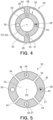
- the second tubular portion 30 when the second tubular portion 30 is viewed in cross section perpendicular to an axial direction X, four pathways (lumens) 36, 37, 38, and 39 may be formed around the second fluid channel 32, that is, in a wall defining the second fluid channel 32.
- the four pathways may be formed in the second tubular portion 30.
- the pathways 36 and 37 respectively allow pull wires 54 and 55 (to be described) to pass therethrough.
- the pathways 38 and 39 are thermocouple pathways that allow a thermocouple 42 of the temperature sensor 40 (to be described) to pass therethrough.
- the interior of the first tubular portion 20 is provided with a first fluid channel 22 through which the fluid flows. More specifically, the first fluid channel 22 is formed inside the first tubular portion 20, that is, a space between the first tubular portion 20 and the second tubular portion 30. As illustrated in FIG. 2 , a proximal end of the first tubular portion 20 (right end in FIG. 2 ) is connected to the distal end of the handle 10 (left end in FIG. 2 ). The interior of the first tubular portion 20 does not communicate with the interior of the handle 10 and the interior of the second tubular portion 30, and the fluid injected from the fluid feeding port 14 does not flow into the first fluid channel 22 inside the first tubular portion 20.
- the first tubular portion 20 is provided with a first opening 24.
- the first opening 24 leads to the interior of the first tubular portion 20.
- the first fluid channel 22 inside the first tubular portion 20 communicates with the outside of the first tubular portion 20 through the first opening 24.
- the first opening 24 is disposed on the leading end of the first tubular portion 20, opening at the leading end of the first tubular portion 20.
- the invention is not limited to this embodiment, and the first opening 24 may be disposed on a side surface of the first tubular portion 20.
- more than one first opening 24 may be disposed on the side surface of the first tubular portion 20.
- the fluid outside the first tubular portion 20 (outside the catheter 1) is collected inside the first tubular portion 20 from the first opening 24.
- the fluid fed from the second opening 34 to an internal organ such as the esophagus is designed to flow into the first fluid channel 22 inside the first tubular portion 20 from the first opening 24 after cooling or heating the internal organ.
- the side surface of the first tubular portion 20 on the proximal side is provided with a fluid collector 26.
- the fluid collector 26 communicates with the first fluid channel 22, and the fluid flowing through the first fluid channel 22 is collected by this fluid collector 26.
- the fluid collector 26 may be connected through a tube to an aspiration device (not illustrated) provided with an aspiration pump, and the fluid may be aspirated from the first opening 24 when the aspiration pump is driven to negatively reduce the pressure inside the first fluid channel 22.
- the fluid collector 26 may be connected to a syringe (not illustrated ) through a tube, and the fluid may be collected from the first opening 24 by an operator operating the syringe.
- an inner side surface of the first tubular portion 20 and an outer side surface of the second tubular portion 30 may be partially coupled via a connection 28, and the first tubular portion 20 and the second tubular portion 30 may be integrated.
- the first tubular portion 20 and the second tubular portion 30 may be formed seamlessly in an integrated manner, using the same material at the time of manufacturing.
- the first tubular portion 20 and the second tubular portion 30 may be integrally molded of the same material.
- the leading end of the first tubular portion 20 may be tapered.
- the first tubular portion 20 may have a length of 200 mm or more and 1000 mm or less.
- the first tubular portion 20 may have an inside diameter of 1.0 mm or more and 5.0 mm or less.
- the first tubular portion 20 may have an outside diameter of 1.7 mm or more and 6.0 mm or less.
- the second tubular portion 30 may have a length of 300 mm or more and 1100 mm or less.
- the second tubular portion 30 may have an outside diameter of 2.3 mm or more and 4.0 mm or less.
- the first tubular portion 20 and the second tubular portion 30 may employ any material as long as the material is flexible that enables transnasal or transoral insertion into the body.
- Examples of such a flexible material include polyvinyl chloride, silicone, polyether block amide, polyurethane, nylon, polyolefin, polyamide and polyether polyamide.
- a material suitable for contrast radiography is mixed in the flexible material.
- the fluid to be injected through the catheter 1 may employ any fluid as long as the fluid is used for controlling temperature of an internal organ, such as saline, dextrose in water, purified water and tap water.
- the fluid temperature may be controlled.
- fluid to be used in heat-based catheter ablation, may have a temperature of 0°C or more and 10°C or less, and in cold-based catheter ablation, fluid to be used may have a temperature of 25°C or more and 37°C or less.
- the temperature sensor 40 measures temperature of an internal organ of a patient when the catheter 1 is used.
- the temperature sensor 40 includes the measuring unit 41 placed in the extension 31 of the second tubular portion 30 and the thermocouple 42 configured to measure temperature of the measuring unit 41.
- the measuring unit 41 have heat conductivity and have a tubular shape. As illustrated in FIGS. 1 and 6 , the measuring unit 41 may be disposed on the side surface 35 of the extension 31 of the second tubular portion 30. In the illustrated example, the measuring unit 41 is placed between the first opening 24 and the second opening 34 in the longitudinal direction X. Furthermore, a plurality of measuring units 41 is disposed on the side surface 35 of the extension 31 of the second tubular portion 30, being separated from each other in the longitudinal direction X (along the central axis O2 of the second tubular portion 30). Furthermore, the measuring unit 41 and the second opening 34 are placed alternately along the longitudinal direction X (the central axis O2 of the second tubular portion 30).
- one measuring unit 41 may be disposed on the side surface 35 of the extension 31 of the second tubular portion 30, or the measuring unit 41 may be disposed on the leading end of the second tubular portion 30.
- the measuring unit 41 may employ any material as long as the material has high heat conductivity. Examples of the material include metallic materials such as iron, aluminum, stainless steel, and platinum alloys.
- the thermocouple 42 includes two metal wires of different types. As illustrated in FIGS. 4 to 6 , the thermocouple 42 passes through the thermocouple pathway 38 in the second tubular portion 30. The thermocouple 42 may pass through the thermocouple pathway 39. A terminal of the thermocouple 42 is connected to the main body of the gauge (not illustrated) through the cable 16 as described above. On the other hand, as illustrated in FIG. 6 , a leading end of the thermocouple 42 penetrates an inner wall of the second tubular portion 30 to be connected to the measuring unit 41 at a position where the measuring unit 41 is placed in the longitudinal direction X. More specifically, the leading end of the thermocouple 42 is fixed to the measuring unit 41, being in contact with the measuring unit 41.
- thermocouple 42 may be fixed to the measuring unit 41 by, for example, soldering.
- a plurality of thermocouples 42 passes through the thermocouple pathways 38 and 39, and leading ends of the thermocouples 42 penetrate the inner wall of the second tubular portion 30 to be connected to the measuring units 41 at position where each measuring unit 41 is placed.
- the combination of the metal wires included in the thermocouple 42 is, for example, a copper wire and a constantan wire.
- thermocouple 42 In using the catheter 1, when the second tubular portion 30 is inserted into the internal organ of the patient, temperature (heat) of the internal organ is transmitted to the measuring unit 41 placed in the extension 31 of the second tubular portion 30.
- the temperature sensor 40 measures temperature of the internal organ by measuring temperature of the measuring unit 41 with the thermocouple 42.
- the measuring unit 41 is not limited to a tubular shape and may have any other shape.
- the leading end of the thermocouple 42 may serve as a measuring unit.
- the measuring unit may include the leading end of the thermocouple 42.
- the catheter 1 may also include the deflection mechanism 50 that deflects the leading end of the extension 31 of the second tubular portion 30.
- the deflection mechanism 50 is connected to the deflecting lever 12 and is placed inside the handle 10.
- the deflection mechanism 50 includes a rotor 51, a first pull wire 54, and a second pull wire 55.
- the rotor 51 is connected to the deflecting lever 12 and is rotatably supported by a rotating shaft C.
- the deflecting lever 12 inclined in the longitudinal direction X causes the rotor 51 to rotate about the rotating shaft C.
- the rotor 51 has a side surface provided with an inner race 52, a first protrusion 53a and a second protrusion 53b.
- the inner race 52 is placed inside the rotor 51 and protrudes from a central portion of the side surface of the rotor 51.
- Each of the first protrusion 53a and the second protrusion 53b protrudes from the side surface of the rotor 51 on the distal side (the left side in FIG. 2 ).
- the first protrusion 53a is placed on one side (upper side in FIG. 2 ) in the direction perpendicular to the longitudinal direction X
- the second protrusion 53b is placed on the other side (lower side in FIG. 2 ) in the direction perpendicular to the longitudinal direction X.
- One end of the first pull wire 54 and one end of the second pull wire 55 are connected to the side surface of the rotor 51.
- first pull wire 54 and one end of the second pull wire 55 are connected to the side surface of the rotor 51 on the proximal side (right side in FIG. 2 ).
- the first pull wire 54 is connected to a part on one side (upper side in FIG. 2 ) in the direction perpendicular to the longitudinal direction X
- the second pull wire 55 is connected to a part on the other side (lower side in FIG. 2 ) in the direction perpendicular to the longitudinal direction X.
- the first pull wire 54 and the second pull wire 55 both pass between the first protrusion 53a and the second protrusion 53b. As illustrated in FIG.
- the pull wires 54 and 55 pass through the pull wire pathways 36 and 37, respectively, and the other ends of the pull wires 54 and 55 are connected to the leading end of the extension 31 of the second tubular portion 30.
- the pull wires 54 and 55 have predetermined tension between the rotor 51 and the leading end of the extension 31 of the second tubular portion 30.
- the deflection mechanism 50 is configured to deflect the leading end of the extension 31 of the second tubular portion 30 toward one side (lower side in FIG. 7 ) in the direction perpendicular to the longitudinal direction X when the deflecting lever 12 is inclined toward the distal side (left side in FIG. 7 ). Furthermore, the deflection mechanism 50 is configured to deflect the leading end of the extension 31 of the second tubular portion 30 toward the other side (upper side in FIG. 7 ) in the direction perpendicular to the longitudinal direction X when the deflecting lever 12 is inclined toward the proximal side (right side in FIG. 7 ). More specifically, as illustrated in FIG.
- the leading end of the extension 31 of the second tubular portion 30 is pulled by the second pull wire 55 and receives a force on one side (lower side in FIG. 7 ) in the direction perpendicular to the longitudinal direction X. Accordingly, the leading end of the extension 31 of the second tubular portion 30 is deflected toward one side (the leading end faces one side). Furthermore, as illustrated in FIG. 9 , the deflecting lever 12 inclined toward the proximal side causes the rotor 51 to rotate clockwise in FIG. 9 and loosens the second pull wire 55 to decrease the tension of the second pull wire 55 while pulling the first pull wire 54 in contact with an outer peripheral portion of the inner race 52 to increase the tension of the first pull wire 54.
- the leading end of the extension 31 of the second tubular portion 30 is pulled by the first pull wire 54 and receives a force on the other side (upper side in FIG. 7 ) in the direction perpendicular to the longitudinal direction X. Accordingly, the leading end of the extension 31 of the second tubular portion 30 is deflected toward the other side (the leading end faces the other side).
- the catheter 1 is employed, for example, in catheter ablation using a separate ablation catheter.
- a leading end of an ablation catheter inserted into the body ablates an internal organ to be treated such as a site of interest in the heart.
- temperature of other internal organs near the internal organ to be ablated also changes.
- the catheter 1 is used to cool an internal organ heated by the catheter ablation or to heat an internal organ cooled by the catheter ablation.
- operations and effects when temperature of the esophagus is controlled with the catheter 1 during the catheter ablation of a site of interest in the heart.
- the catheter 1 is inserted into the esophagus from the nose or mouth of a patient lying on his/her back. More specifically, an operator inserts the first tubular portion 20 and the second tubular portion 30 of the catheter 1 into the esophagus of the patient while holding the handle 10 of the catheter 1.
- the deflecting lever 12 may be operated to deflect the leading end of the extension 31 of the second tubular portion 30. Accordingly, the second tubular portion 30 is smoothly guided into the esophagus of the patient.
- temperature inside the esophagus of the patient is measured by the temperature sensor 40 of the catheter 1. More specifically, temperature (heat) of the esophagus is transmitted to the measuring unit 41 placed in the extension 31 of the second tubular portion 30, and the temperature transmitted to the measuring unit 41 is measured by the thermocouple 42 of the temperature sensor 40.
- the temperature measured by the temperature sensor 40 is displayed on the main body of the gauge (not illustrated), which enables the operator to monitor the temperature inside the esophagus of the patient.
- temperature-controlled fluid is injected through the catheter 1 from the fluid feeding port 14.
- the fluid injected from the fluid feeding port 14 flows into the second tubular portion 30 and flows through the second fluid channel 32 inside the second tubular portion 30.
- the fluid flowing through the second fluid channel 32 is discharged (ejected) from the second opening 34 placed in the extension 31 of the second tubular portion 30 to the outside of the second tubular portion 30, that is, to the esophagus. Accordingly, the esophagus of the patient is cooled or heated by the fluid.
- the fluid discharged into the esophagus from the second opening 34 cools or heats the esophagus and is collected inside the first tubular portion 20 from the first opening 24, and then, flows through the first fluid channel 22 inside the first tubular portion 20.
- the fluid flowing through the first fluid channel 22 is collected by the fluid collector 26. In this manner, the fluid discharged from the second opening 34 is collected from the first opening 24.
- the catheter 1 includes the temperature sensor 40, and the fluid discharged from the second opening 34 is collected from the first opening 24.
- the single catheter 1 has functions of temperature measurement, fluid discharge and fluid collection. Such a configuration avoids complication of the device and simplifies operations such as temperature measurement, fluid discharge and fluid collection.
- the catheter 1 includes the first tubular portion 20 provided with the first opening 24 for fluid collection and the second tubular portion 30 provided with the second opening 34 for fluid discharge.
- the first opening 24 for fluid collection is placed on the proximal side of the second opening 34 for fluid discharge.
- the fluid discharged from the second opening 34 is prevented from flowing into the trachea on the proximal side of the esophagus when the catheter 1 is inserted into the esophagus of the patient. Accordingly, it is possible to reduce patient burden.
- the measuring unit 41 is placed between the first opening 24 and the second opening 34 in the longitudinal direction X. Since the fluid is discharged from the second opening 34 and collected from the first opening 24, a portion between the first opening 24 and the second opening 34 is a main site of interest whose temperature is to be controlled. For this reason, placing the measuring unit 41 between the first opening 24 and the second opening 34 makes it possible to measure temperature of the site of interest with high accuracy. Consequently, temperature of the site of interest is perceived accurately, which enables temperature control of the internal organ more efficiently.
- the first opening 24 opens at the leading end of the first tubular portion 20.
- the first opening 24 is prevented from aspirating the inner wall surface of the esophagus or the like. For this reason, it is possible to suppress a decrease in aspiration force from the first opening 24, which enables efficient collection of the fluid.
- the first opening 24 for fluid collection opens towards the second opening 34 for fluid feeding, and even for this reason, the fluid fed from the second opening 34 into the body is efficiently collected.
- the second opening 34 includes a plurality of openings disposed on the side surface 35 of the extension 31 of the second tubular portion 30, the openings being separated from each other along the central axis O2 of the second tubular portion 30.
- the fluid is ejected from the plurality of second openings 34 disposed on the side surface 35 of the extension 31 of the second tubular portion 30 to the inner wall surface of the esophagus or the like having high or low temperature. Accordingly, it is possible to quickly cool or heat the inner wall surface of the esophagus or the like, which enables temperature control of the internal organ more efficiently.
- the temperature sensor 40 has the plurality of measuring units 41 placed alternately with the second opening 34 along the central axis O2 of the second tubular portion 30.
- the second opening 34 includes the plurality of openings disposed on the side surface 35 of the extension 31 of the second tubular portion 30, the openings being separated from each other in a circumferential direction around the central axis O2 of the second tubular portion 30.
- the fluid is sprayed from the plurality of second openings 34 to the inner wall surface of the esophagus or the like in a wide range in the circumferential direction. Accordingly, it is possible to uniformly cool or heat the inner wall surface of the esophagus or the like, which enables temperature control of the internal organ more efficiently.
- first tubular portion 20 and the second tubular portion 30 are integrated. That is, the first tubular portion 20 and the second tubular portion 30 are formed seamlessly, and typically, the first tubular portion 20 and the second tubular portion 30 are molded in an integrated manner. With this configuration, the second fluid channel 32 in the second tubular portion 30 is successfully prevented from being blocked by the first tubular portion 20. It is also possible to successfully prevent the first opening 24 from being closed by the second tubular portion 30. Accordingly, internal organ temperature is controlled stably.
- the leading end of the first tubular portion 20 is tapered. With this configuration, for example, the leading end of the first tubular portion 20 is prevented from being caught in the nasal cavity or the pharynx when the first tubular portion 20 is inserted into the esophagus. Accordingly, the catheter 1 is smoothly guided into the esophagus.
- the embodiment shows an example in which there is the plurality of second openings 34, the second openings 34 have a substantially equal area.
- the second openings 34 may have different areas.
- an area of a second opening 34 on the distal side may be larger than an area of another second opening 34 on the proximal side.
- one second opening 34 among the plurality of second openings 34 may have a larger area than that of another second opening 34 on the proximal side of the foregoing second opening 34.
- the second openings 34 may have an area increasing from the proximal side toward the distal side.
- any one second opening 34 among the plurality of second openings 34 may have an area equal to or larger than another second opening 34 on the proximal side of the foregoing second opening 34.
- the fluid tends to be discharged from the second opening 34 on the proximal side (on the upper side) more easily than from the second opening 34 on the distal side (on the lower side). For this reason, making an area of the second opening 34 on the distal side larger than an area of the second opening 34 on the proximal side uniforms an amount of fluid discharged from each second opening 34. Accordingly, the inner wall surface of the esophagus or the like is uniformly cooled or heated in the longitudinal direction, which enables temperature control of the internal organ more efficiently.
- an area of one second opening 34 among the plurality of second openings 34 may be larger than an area of another second opening 34 on the proximal side of the foregoing second opening 34 and may be larger than an area of another second opening 34 on the distal side of the foregoing second opening 34.
- the embodiment shows an example in which the fluid discharged from the second opening 34 is collected from the first opening 24.
- the invention is not limited to this embodiment, and the fluid discharged from the first opening 24 may be collected from the second opening 34. In this case, the fluid flows against the direction of the embodiment.
- the embodiment shows an example in which the catheter 1 is inserted into the esophagus of a patient.
- the invention is not limited to this embodiment, and the catheter 1 may be inserted into any internal organs in need of temperature control.
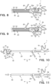
- the second embodiment illustrated in FIGS. 10 and 11 is substantially equal to the first embodiment illustrated in FIGS. 1 to 9 except that an extension of a second tubular portion has a corrugated shape curved toward one side and another side.
- FIGS. 10 and 11 the same parts as those in the first embodiment illustrated in FIGS. 1 to 9 are denoted by the same reference numerals and will not hereinafter be described in detail.
- an extension 31 of a second tubular portion 30 has a corrugated shape curved toward one side (upper side in FIG. 10 ) and the other side (lower side in FIG. 10 ). More specifically, the corrugated shape has a first curved portion 61 curved toward one side, a second curved portion 62 curved toward the other side and an intermediate portion 63 between the first curved portion 61 and the second curved portion 62. In the illustrated example, the corrugated shape has one first curved portion 61 and one second curved portion 62, but the invention is not limited to this embodiment, and the corrugated shape may have two or more first curved portions 61 and/or two or more second curved portions 62.
- the extension 31 of the second tubular portion 30 may be bent to be alternately folded back on one side and the other side in a direction perpendicular to longitudinal direction X.
- the second tubular portion 30 may include a flexible material that memorizes the corrugated shape.
- the material of a first tubular portion 20 and the second tubular portion 30 include thermoplastic materials such as polyvinyl chloride, silicone, polyether block amide, polyurethane, nylon, polyolefin, polyamide and polyether polyamide, and shape-memory alloys such as nickel titanium alloy.
- a plurality of measuring units 41 is disposed on a side surface 35 of the extension 31 of the second tubular portion 30, being separated from each other along the central axis O2 of the second tubular portion 30. Furthermore, the measuring units 41 are placed alternately with second openings 34 along the central axis O2 of the second tubular portion 30. In the illustrated example, the measuring units 41 are placed in the first curved portion 61, the second curved portion 62 and the intermediate portion 63, respectively. The second openings 34 are placed between each measuring units 41, respectively.
- the second openings 34 are placed between the measuring unit 41 in the first curved portion 61 and the measuring unit 41 in the intermediate portion 63, and between the measuring unit 41 in the second curved portion 62 and the measuring unit 41 in the intermediate portion 63, respectively.
- the invention is not limited to this embodiment, and the measuring units 41 and the second openings 34 may be at any positions in the extension 31 of the second tubular portion 30.
- the second tubular portion 30 is movable relative to the first tubular portion 20.
- the first tubular portion 20 has a proximal end (right end in FIG. 10 ) connected to a distal end of the handle 10 (left end in FIG. 10 ).
- the second tubular portion 30 has a proximal end not connected to the handle 10 but passing through the handle 10 and extending from a proximal end of the handle 10.
- the second tubular portion 30 has a proximal extension 64 extending from the proximal side of the handle 10.
- the second tubular portion 30 is moved to the distal side in the longitudinal direction X relative to the first tubular portion 20. Accordingly, as illustrated in FIG. 10 , the extension 31 of the second tubular portion 30 is extended to the outside and forms the memorized corrugated shape.
- the proximal extension 64 may be provided with a fluid feeding port 14 communicating with a second fluid channel 32 inside the second tubular portion 30. The operator injects fluid through the catheter 1 from the fluid feeding port 14.
- the handle 10 may be provided with a moving lever 65 instead of the deflecting lever 12 employed in the first embodiment.
- the moving lever 65 is movable in the longitudinal direction X by being operated by the operator with his/her finger or the like.
- the moving lever 65 is connected to the second tubular portion 30 inside the handle 10. With this configuration, when the moving lever 65 is moved in the longitudinal direction X, the second tubular portion 30 also moves in the longitudinal direction X together with the moving lever 65. In this manner, movement of the moving lever 65 in the longitudinal direction X also moves the second tubular portion 30 in the longitudinal direction X.
- the extension 31 of the second tubular portion 30 has a corrugated shape curved toward one side and the other side.
- the fluid is fed from the second openings 34 to an internal organ such as the esophagus while the internal organ is expanded by the corrugated shape of the extension 31 of the second tubular portion 30.
- the second tubular portion 30 is movable relative to the first tubular portion 20 and configured to be housed in the first tubular portion 20.
- the extension 31 of the second tubular portion 30 has a corrugated shape, the second tubular portion 30 is smoothly guided to an internal organ of a patient such as the esophagus by being housed in the first tubular portion 20.
- the measuring units 41 are placed in the first curved portion 61, the second curved portion 62 and the intermediate portion 63 of the corrugated shape, respectively.
- the third embodiment illustrated in FIGS. 12 and 13 is substantially equal to the first embodiment illustrated in FIGS. 1 to 9 except that a first tubular portion and a second tubular portion each have a substantially semicircular shape when viewed in a cross section perpendicular to an axial direction.
- a first tubular portion and a second tubular portion each have a substantially semicircular shape when viewed in a cross section perpendicular to an axial direction.
- the same parts as those in the first embodiment illustrated in FIGS. 1 to 9 are denoted by the same reference numerals and will not hereinafter be described in detail.
- a first tubular portion 20 and a second tubular portion 30 each have a substantially semicircular shape when viewed in a cross section perpendicular to an axial direction X.
- the first tubular portion 20 and the second tubular portion 30 are integrated to form a circular shape.
- the first tubular portion 20 and the second tubular portion 30 may be formed seamlessly in an integrated manner, using the same material at the time of manufacturing.
- the first tubular portion 20 and the second tubular portion 30 may be integrally molded of the same material.
- a leading end 29 of the first tubular portion 20 is formed to have a cross section illustrated in FIG. 13 .
- the second tubular portion 30 includes an extension 31 extending beyond the leading end 29 of the first tubular portion 20.
- the extension 31 of the second tubular portion 30 has a circular cross section.
- the interior of the first tubular portion 20 is provided with a first fluid channel 22.
- the first tubular portion 20 is provided with a first opening 24 communicating with the interior of the first tubular portion 20.
- the first opening 24 is disposed on a side surface of the first tubular portion 20.
- the first fluid channel 22 inside the first tubular portion 20 communicates with the outside of the first tubular portion 20 through this first opening 24.
- the first fluid channel 22 inside the first tubular portion 20 also communicates with a fluid collector 26.
- the interior of the second tubular portion 30 is provided with a second fluid channel 32.
- the second tubular portion 30 is provided with a second opening 34 communicating with the interior of the second tubular portion 30.
- a plurality of second openings 34 is disposed on a side surface 35 of the extension 31 of the second tubular portion 30, being separated from each other in the longitudinal direction X (along the central axis O2 of the second tubular portion 30).
- the second opening 34 is placed alternately with a measuring unit 41 along the longitudinal direction X (the central axis O2 of the second tubular portion 30).
- a plurality of second openings 34 is disposed on the side surface 35 of the extension 31 of the second tubular portion 30, being separated from each other in a circumferential direction around the central axis O2 of the second tubular portion 30.
- the second fluid channel 32 inside the second tubular portion 30 communicates with the outside of the second tubular portion 30 through this second opening 34.
- the second fluid channel 32 inside the second tubular portion 30 also communicates with a fluid feeding port 14.
- the fluid injected from the fluid feeding port 14 flows through the second fluid channel 32 inside the second tubular portion 30 and is discharged (ejected) from the second opening 34 to the outside of the second tubular portion 30, that is, to the esophagus. Accordingly, the esophagus of the patient is cooled or heated by the fluid. The fluid after cooling or heating the esophagus is collected inside the second tubular portion 30 from the first opening 24 and flows through the first fluid channel 22 inside the second tubular portion 30, thereby being collected by the fluid collector 26.
- a catheter 1 includes the first tubular portion 20 provided with the first opening 24 communicating with the interior of the first tubular portion 20; the second tubular portion 30 having the extension 31 extending beyond the leading end 29 of the first tubular portion 20 and provided with the second opening 34 communicating with the interior of the second tubular portion 30; and the temperature sensor 40 configured to measure temperature of the measuring unit 41 placed in the extension 31 of the second tubular portion 30, and the catheter 1 is configured to collect the fluid discharged from the second opening 34 from the first opening 24. Note that the fluid discharged from the first opening 24 may be collected from the second opening 34.
- the catheter 1 includes a temperature sensor 40, and the fluid discharged from the second opening 34 is collected from the first opening 24.
- the fluid discharged from the first opening 24 is collected from the second opening 34.
- the first tubular portion 20 and the second tubular portion 30 are integrated to form a circular shape when viewed in a cross section perpendicular to the axial direction X.
- FIGS. 14 and 15 The fourth embodiment illustrated in FIGS. 14 and 15 is substantially equal to the first embodiment illustrated in FIGS. 1 to 9 except that a first tubular portion and a second tubular portion are extending in parallel.
- FIGS. 14 and 15 the same parts as those in the first embodiment illustrated in FIGS. 1 to 9 are denoted by the same reference numerals and will not hereinafter be described in detail.
- a second tubular portion 30 does not pass through a first tubular portion 20, and the first tubular portion 20 and the second tubular portion 30 are extending in parallel.
- a proximal end (right end in FIG. 14 ) of the first tubular portion 20 is connected to a distal end (left end in FIG. 14 ) of a handle 10
- a proximal end of the second tubular portion 30 is connected to the distal end of the handle 10.
- the second tubular portion 30 is larger than the first tubular portion 20 in length in the longitudinal direction X. For this reason, the second tubular portion 30 has an extension 31 extending beyond a leading end 29 of the first tubular portion 20.
- a side surface of the first tubular portion 20 and a side surface of the second tubular portion 30 may be in contact with each other.
- the invention is not limited to this embodiment, and the side surface of the first tubular portion 20 and the side surface of the second tubular portion 30 may be separated from each other.
- the first tubular portion 20 and the second tubular portion 30 may be integrated. In this case, the first tubular portion 20 and the second tubular portion 30 may be formed in an integrated manner, using the same material at the time of manufacturing.
- the interior of the first tubular portion 20 is provided with a first fluid channel 22.
- the first tubular portion 20 is provided with a first opening 24 communicating with the interior of the first tubular portion 20.
- the first opening 24 opens at the leading end 29 of the first tubular portion 20.
- the first fluid channel 22 inside the first tubular portion 20 communicates with the outside of the first tubular portion 20 through this first opening 24.
- the first fluid channel 22 inside the first tubular portion 20 also communicates with a fluid collector 26.
- the interior of the second tubular portion 30 is provided with a second fluid channel 32.
- the second tubular portion 30 is provided with a second opening 34 communicating with the interior of the second tubular portion 30.
- a plurality of second openings 34 is disposed on a side surface 35 of the extension 31 of the second tubular portion 30, being separated from each other in the longitudinal direction X (along the central axis O2 of the second tubular portion 30).
- the second opening 34 is placed alternately with a measuring unit 41 along the longitudinal direction X (the central axis O2 of the second tubular portion 30).
- a plurality of second openings 34 is disposed on the side surface 35 of the extension 31 of the second tubular portion 30, being separated from each other in a circumferential direction around the central axis O2 of the second tubular portion 30.
- the second fluid channel 32 inside the second tubular portion 30 communicates with the outside of the second tubular portion 30 through this second opening 34.
- the second fluid channel 32 inside the second tubular portion 30 also communicates with a fluid feeding port 14.
- the fluid injected from the fluid feeding port 14 flows through the second fluid channel 32 inside the second tubular portion 30 and is discharged (ejected) from the second opening 34 to the outside of the second tubular portion 30, that is, to the esophagus. Accordingly, the esophagus of the patient is cooled or heated by the fluid.
- the fluid after cooling or heating the esophagus is collected inside the first tubular portion 20 from the first opening 24, and flows through the first fluid channel 22 inside the first tubular portion 20, thereby being collected by the fluid collector 26.
- a catheter 1 similarly to the third embodiment, includes the first tubular portion 20 provided with the first opening 24 communicating with the interior of the first tubular portion 20; the second tubular portion 30 having the extension 31 extending beyond the leading end 29 of the first tubular portion 20 and provided with the second opening 34 communicating with the interior of the second tubular portion 30; and the temperature sensor 40 configured to measure temperature of the measuring unit 41 placed in the extension 31 of the second tubular portion 30, and the catheter 1 is configured to collect fluid discharged from the second opening 34 from the first opening 24. Note that the fluid discharged from the first opening 24 may be collected from the second opening 34.
- the catheter 1 includes a temperature sensor 40, and the fluid discharged from the second opening 34 is collected from the first opening 24.
- the fluid discharged from the first opening 24 is collected from the second opening 34.
- the manufacturing of the catheter 1 is facilitated, and the manufacturing cost of the catheter 1 is reduced. Furthermore, it is possible to independently secure a channel through which the injected fluid flows and a channel through which the collected fluid flows. Accordingly, it is possible to freely control an injection pressure at the time of injecting the fluid and an aspiration pressure at the time of collecting the fluid, which enables efficient temperature control of the internal organ.
Landscapes
- Health & Medical Sciences (AREA)
- Life Sciences & Earth Sciences (AREA)
- Engineering & Computer Science (AREA)
- Public Health (AREA)
- Biomedical Technology (AREA)
- Heart & Thoracic Surgery (AREA)
- Veterinary Medicine (AREA)
- Animal Behavior & Ethology (AREA)
- General Health & Medical Sciences (AREA)
- Surgery (AREA)
- Biophysics (AREA)
- Anesthesiology (AREA)
- Hematology (AREA)
- Pulmonology (AREA)
- Otolaryngology (AREA)
- Physics & Mathematics (AREA)
- Nuclear Medicine, Radiotherapy & Molecular Imaging (AREA)
- Medical Informatics (AREA)
- Molecular Biology (AREA)
- Cardiology (AREA)
- Plasma & Fusion (AREA)
- Vascular Medicine (AREA)
- Thermal Sciences (AREA)
- Media Introduction/Drainage Providing Device (AREA)
Abstract
Description
- The present invention relates to a catheter.
- In catheter ablation known as a treatment for arrhythmia such as atrial fibrillation, an ablation catheter is inserted into the body, and a leading end of the ablation catheter is heated or cooled to ablate a site of interest in the heart. In this catheter ablation, there is a possibility that heat of ablation is transmitted to an internal organ near the heart such as the esophagus and damages the internal organ.
-
Patent Literature 1 discloses an invention of a temperature measurement catheter which is inserted into an internal organ such as the esophagus when catheter ablation is performed. According to the invention disclosed inPatent Literature 1, internal temperature of the esophagus or the like is monitored, and when the internal temperature is high or low, the catheter ablation is temporarily stopped to provide a cooling time. - Patent Literature 1:
JP 2016-119936 A - However, the aforementioned approach takes time and potentially causes an increase in patient burden. For this reason, it is required to efficiently control temperature of an internal organ.
- The present invention has been made in light of such problems, and an object of the invention is to provide a catheter capable of controlling temperature of an internal organ efficiently.
- A catheter according to the invention includes: a first tubular portion provided with a first opening communicating with an interior of the first tubular portion; a second tubular portion passing through the first tubular portion, the second tubular portion having an extension extending from a leading end of the first tubular portion and provided with a second opening communicating with an interior of the second tubular portion; and a temperature sensor configured to measure temperature of a measuring unit placed in the extension of the second tubular portion, in which the catheter is configured to collect fluid discharged from one of the first opening and the second opening from another one of the first opening and the second opening.
- In the catheter, the measuring unit may be placed between the first opening and the second opening in a longitudinal direction of the catheter.
- In the catheter, the catheter may be configured to collect the fluid discharged from the second opening from the first opening.
- In the catheter, the first opening may open at the leading end of the first tubular portion.
- In the catheter, the second opening may include a plurality of openings disposed on a side surface of the extension of the second tubular portion, the openings being separated from each other along a central axis of the second tubular portion.
- In the catheter, the temperature sensor may have a plurality of the measuring units placed alternately with the second opening along the central axis of the second tubular portion.
- In the catheter, one of the plurality of openings of the second opening may have an area larger than an area of another opening disposed on the proximal side of the one opening.
- In the catheter, the second opening may include a plurality of openings disposed on a side surface of the extension of the second tubular portion, the openings being separated from each other in a circumferential direction around the central axis of the second tubular portion.
- In the catheter, the first tubular portion and the second tubular portion may be integrated.
- In the catheter, the extension of the second tubular portion may have a corrugated shape curved toward one side and another side.
- In the catheter, the second tubular portion may be movable relative to the first tubular portion and configured to be housed in the first tubular portion.
- In the catheter, the corrugated shape may has a first curved portion curved toward the one side, a second curved portion curved toward the other side and an intermediate portion between the first curved portion and the second curved portion, and the measuring unit may be placed in the first curved portion, the second curved portion and the intermediate portion, respectively.
- Furthermore, a catheter according to the invention includes: a first tubular portion provided with a first opening communicating with an interior of the first tubular portion; a second tubular portion having an extension extending beyond a leading end of the first tubular portion and provided with a second opening communicating with an interior of the second tubular portion; and a temperature sensor configured to measure temperature of a measuring unit placed in the extension of the second tubular portion, in which the catheter is configured to collect fluid discharged from one of the first opening and the second opening from another one of the first opening and the second opening.
- According to the invention, it is possible to efficiently control temperature of an internal organ.
-
-
FIG. 1 is a schematic view of a catheter according to a first embodiment. -
FIG. 2 is an enlarged cross-sectional view of a proximal part of the catheter illustrated inFIG. 1 . -
FIG. 3 is an enlarged cross-sectional view of a distal part of the catheter illustrated inFIG. 1 . -
FIG. 4 is a cross-sectional view taken along line A-A inFIG. 1 . -
FIG. 5 is a cross-sectional view taken along line B-B inFIG. 1 . -
FIG. 6 is a cross-sectional view taken along line C-C inFIG. 1 . -
FIG. 7 is a view for describing an operation of deflecting a leading end of the catheter illustrated inFIG. 1 . -
FIG. 8 is a schematic view of a deflection mechanism when a deflecting lever inFIG. 7 is placed on the proximal side. -
FIG. 9 is a schematic view of the deflection mechanism when the deflecting lever inFIG. 7 is placed on the distal side. -
FIG. 10 is a schematic view of a catheter according to a second embodiment. -
FIG. 11 is a schematic view illustrating a second tubular portion being housed in a first tubular portion of the catheter illustrated inFIG. 10 . -
FIG. 12 is a schematic view of a catheter according to a third embodiment. -
FIG. 13 is a cross-sectional view taken along line D-D inFIG. 12 . -
FIG. 14 is a schematic view of a catheter according to a fourth embodiment. -
FIG. 15 is a cross-sectional view taken along line E-E inFIG. 14 . - Hereinafter, an embodiment of the invention will be described with reference to the drawings. In the drawings attached to this description, the scale and longitudinal and lateral dimensional ratios are exaggerated and changed from the actual ones for sake of simplicity.
- First, with reference to
FIGS. 1 to 9 , a catheter according to a first embodiment will be described. - As illustrated in
FIG. 1 , acatheter 1 according to this embodiment includes ahandle 10, a firsttubular portion 20 extending from thehandle 10, a secondtubular portion 30 passing through and extending from the firsttubular portion 20, and atemperature sensor 40 that measures temperature. - First, the
handle 10 will be described. In using thecatheter 1, an operator holds thehandle 10. Thehandle 10 may have a cylindrical shape. In the illustrated example, thehandle 10 is provided with a deflectinglever 12, afluid feeding port 14, and acable 16. - The deflecting
lever 12 is operated by, for example, the operator with his/her finger and is inclined in a longitudinal direction of the catheter 1 (horizontal direction inFIG. 1 , hereinafter referred to as "longitudinal direction X") when being pushed or pulled by the finger. As illustrated inFIG. 2 , the deflectinglever 12 is connected to adeflection mechanism 50 to be described. As will be described later, for example, when the deflectinglever 12 is inclined toward the distal side in the longitudinal direction X (the left side inFIG. 7 ), thedeflection mechanism 50 deflects a leading end of the catheter 1 (a leading end of anextension 31 of the secondtubular portion 30 to be described later) toward one side (the lower side inFIG. 7 ) in a direction perpendicular to the longitudinal direction X, and when the deflectinglever 12 is inclined toward the proximal side in the longitudinal direction X (the right side inFIG. 7 ), thedeflection mechanism 50 deflects the leading end of thecatheter 1 toward the other side (the upper side inFIG. 7 ) in the direction perpendicular to the longitudinal direction X (seeFIG. 7 ). Such a configuration reduces the risk of thecatheter 1 straying into the air passage, particularly, when thecatheter 1 is applied to the esophagus and inserted into the esophagus either transnasally or transorally. Furthermore, since the esophagus is not linear but meanders from the pharynx to the cardia of the stomach, the deflecting operation makes it possible to place a measuring unit 41 (to be described) at a site of interest in the esophagus. - Note that the term "proximal" represents the side of the
catheter 1 closer to the operator in the longitudinal direction X. The term "distal" represents the side of thecatheter 1 away from the operator in the longitudinal direction X. - The
fluid feeding port 14 is used for injecting fluid through thecatheter 1 and communicates with asecond fluid channel 32 inside the secondtubular portion 30 to be described. Thefluid feeding port 14 may be connected through a tube to a feeding device (not illustrated) provided with a feeding pump, and the fluid may be injected through thecatheter 1 by driving the feeding pump. In this case, the drive of the feeding pump is preferably controlled based on signals detected by thetemperature sensor 40. Alternatively, thefluid feeding port 14 may be connected to a syringe (not illustrated) through a tube, and the fluid may be injected through thecatheter 1 by the operator operating the syringe. - The
cable 16 is used for connecting thecatheter 1 and a gauge (not illustrated), and information detected by the temperature sensor 40 (for example, thermoelectromotive force) is input to the gauge through thecable 16 and converted into temperature information (in vivo temperature). With a display device, the converted temperature information is displayed outside, for example, on a main body of the gauge or an external device (such as monitor and display) connected to the gauge. - Next, the first
tubular portion 20 and the secondtubular portion 30 will be described. The firsttubular portion 20 and the secondtubular portion 30 are to be inserted into the esophagus or other internal organs of a patient when thecatheter 1 is used. As illustrated inFIGS. 1 to 4 , the secondtubular portion 30 has an outside diameter smaller than an inside diameter of the firsttubular portion 20. Furthermore, the secondtubular portion 30 has a larger length than the firsttubular portion 20 in the longitudinal direction X. The secondtubular portion 30 passes through the firsttubular portion 20. For this reason, the secondtubular portion 30 has anextension 31 extending from a leading end of the firsttubular portion 20. In the illustrated example, the firsttubular portion 20 and the secondtubular portion 30 are placed in such a manner that the central axis O1 of the firsttubular portion 20 coincides with the central axis O2 of the secondtubular portion 30. - As illustrated in
FIGS. 2 to 6 , the interior of the secondtubular portion 30 is provided with thesecond fluid channel 32 through which the fluid flows. As illustrated inFIG. 2 , a proximal end of the second tubular portion 30 (right end inFIG. 2 ) is connected to a distal end of the handle 10 (left end inFIG. 2 ). The interior of the secondtubular portion 30 communicates with the interior of thehandle 10, and the fluid injected from thefluid feeding port 14 flows into thesecond fluid channel 32 inside the secondtubular portion 30. - As illustrated in
FIGS. 1 and 3 , theextension 31 of the secondtubular portion 30 is provided with asecond opening 34. Thesecond opening 34 leads to the interior of the secondtubular portion 30. In other words, thesecond fluid channel 32 inside the secondtubular portion 30 communicates with the outside of the secondtubular portion 30 through thesecond opening 34. In the illustrated example, a plurality ofsecond openings 34 is disposed on aside surface 35 of theextension 31 of the secondtubular portion 30, being separated from each other in the longitudinal direction X (along the central axis O2 of the second tubular portion 30). Furthermore, as illustrated inFIG. 5 , the plurality ofsecond openings 34 is disposed on theside surface 35 of theextension 31 of the secondtubular portion 30, being separated from each other in a circumferential direction around the central axis O2 of the secondtubular portion 30. However, the invention is not limited to this embodiment, and onesecond opening 34 may be disposed on theside surface 35 of theextension 31 of the secondtubular portion 30, or thesecond opening 34 may be disposed on a leading end of the secondtubular portion 30. In a case where there is the plurality ofsecond openings 34, thesecond openings 34 may have a substantially equal area. The fluid injected from thefluid feeding port 14 and flowing through thesecond fluid channel 32 inside the secondtubular portion 30 is discharged from thesecond opening 34 to the outside of the second tubular portion 30 (the outside of the catheter 1). In other words, thesecond opening 34 feeds the fluid to the esophagus or other internal organs outside the secondtubular portion 30. Accordingly, the fluid cools or warms the esophagus or other internal organs. - As illustrated in
FIGS. 4 to 6 , when the secondtubular portion 30 is viewed in cross section perpendicular to an axial direction X, four pathways (lumens) 36, 37, 38, and 39 may be formed around thesecond fluid channel 32, that is, in a wall defining thesecond fluid channel 32. In other words, the four pathways may be formed in the secondtubular portion 30. Among these pathways, thepathways pull wires 54 and 55 (to be described) to pass therethrough. Furthermore, thepathways thermocouple 42 of the temperature sensor 40 (to be described) to pass therethrough. - As illustrated in
FIGS. 2 to 4 , the interior of the firsttubular portion 20 is provided with afirst fluid channel 22 through which the fluid flows. More specifically, thefirst fluid channel 22 is formed inside the firsttubular portion 20, that is, a space between the firsttubular portion 20 and the secondtubular portion 30. As illustrated inFIG. 2 , a proximal end of the first tubular portion 20 (right end inFIG. 2 ) is connected to the distal end of the handle 10 (left end inFIG. 2 ). The interior of the firsttubular portion 20 does not communicate with the interior of thehandle 10 and the interior of the secondtubular portion 30, and the fluid injected from thefluid feeding port 14 does not flow into thefirst fluid channel 22 inside the firsttubular portion 20. - As illustrated in
FIGS. 1 and 3 , the firsttubular portion 20 is provided with afirst opening 24. Thefirst opening 24 leads to the interior of the firsttubular portion 20. In other words, thefirst fluid channel 22 inside the firsttubular portion 20 communicates with the outside of the firsttubular portion 20 through thefirst opening 24. In the illustrated example, thefirst opening 24 is disposed on the leading end of the firsttubular portion 20, opening at the leading end of the firsttubular portion 20. However, the invention is not limited to this embodiment, and thefirst opening 24 may be disposed on a side surface of the firsttubular portion 20. Furthermore, more than onefirst opening 24 may be disposed on the side surface of the firsttubular portion 20. The fluid outside the first tubular portion 20 (outside the catheter 1) is collected inside the firsttubular portion 20 from thefirst opening 24. In other words, the fluid fed from thesecond opening 34 to an internal organ such as the esophagus is designed to flow into thefirst fluid channel 22 inside the firsttubular portion 20 from thefirst opening 24 after cooling or heating the internal organ. - As illustrated in
FIGS. 1 and 2 , the side surface of the firsttubular portion 20 on the proximal side is provided with afluid collector 26. Thefluid collector 26 communicates with thefirst fluid channel 22, and the fluid flowing through thefirst fluid channel 22 is collected by thisfluid collector 26. Thefluid collector 26 may be connected through a tube to an aspiration device (not illustrated) provided with an aspiration pump, and the fluid may be aspirated from thefirst opening 24 when the aspiration pump is driven to negatively reduce the pressure inside thefirst fluid channel 22. Alternatively, thefluid collector 26 may be connected to a syringe (not illustrated ) through a tube, and the fluid may be collected from thefirst opening 24 by an operator operating the syringe. - As illustrated in
FIG. 4 , an inner side surface of the firsttubular portion 20 and an outer side surface of the secondtubular portion 30 may be partially coupled via aconnection 28, and the firsttubular portion 20 and the secondtubular portion 30 may be integrated. The firsttubular portion 20 and the secondtubular portion 30 may be formed seamlessly in an integrated manner, using the same material at the time of manufacturing. In particular, the firsttubular portion 20 and the secondtubular portion 30 may be integrally molded of the same material. In addition, the leading end of the firsttubular portion 20 may be tapered. - In the longitudinal direction X, the first
tubular portion 20 may have a length of 200 mm or more and 1000 mm or less. The firsttubular portion 20 may have an inside diameter of 1.0 mm or more and 5.0 mm or less. The firsttubular portion 20 may have an outside diameter of 1.7 mm or more and 6.0 mm or less. Furthermore, in the longitudinal direction X, the secondtubular portion 30 may have a length of 300 mm or more and 1100 mm or less. The secondtubular portion 30 may have an outside diameter of 2.3 mm or more and 4.0 mm or less. The firsttubular portion 20 and the secondtubular portion 30 may employ any material as long as the material is flexible that enables transnasal or transoral insertion into the body. Examples of such a flexible material include polyvinyl chloride, silicone, polyether block amide, polyurethane, nylon, polyolefin, polyamide and polyether polyamide. In addition, in order to check a site where the firsttubular portion 20 and the secondtubular portion 30 indwell in the body, it is more preferable that a material suitable for contrast radiography is mixed in the flexible material. - Furthermore, the fluid to be injected through the
catheter 1 may employ any fluid as long as the fluid is used for controlling temperature of an internal organ, such as saline, dextrose in water, purified water and tap water. The fluid temperature may be controlled. For example, in heat-based catheter ablation, fluid to be used may have a temperature of 0°C or more and 10°C or less, and in cold-based catheter ablation, fluid to be used may have a temperature of 25°C or more and 37°C or less. - Next, the
temperature sensor 40 will be described. Thetemperature sensor 40 measures temperature of an internal organ of a patient when thecatheter 1 is used. Thetemperature sensor 40 includes the measuringunit 41 placed in theextension 31 of the secondtubular portion 30 and thethermocouple 42 configured to measure temperature of the measuringunit 41. - The measuring
unit 41 have heat conductivity and have a tubular shape. As illustrated inFIGS. 1 and6 , the measuringunit 41 may be disposed on theside surface 35 of theextension 31 of the secondtubular portion 30. In the illustrated example, the measuringunit 41 is placed between thefirst opening 24 and thesecond opening 34 in the longitudinal direction X. Furthermore, a plurality of measuringunits 41 is disposed on theside surface 35 of theextension 31 of the secondtubular portion 30, being separated from each other in the longitudinal direction X (along the central axis O2 of the second tubular portion 30). Furthermore, the measuringunit 41 and thesecond opening 34 are placed alternately along the longitudinal direction X (the central axis O2 of the second tubular portion 30). However, the invention is not limited to this embodiment, and one measuringunit 41 may be disposed on theside surface 35 of theextension 31 of the secondtubular portion 30, or the measuringunit 41 may be disposed on the leading end of the secondtubular portion 30. The measuringunit 41 may employ any material as long as the material has high heat conductivity. Examples of the material include metallic materials such as iron, aluminum, stainless steel, and platinum alloys. - The
thermocouple 42 includes two metal wires of different types. As illustrated inFIGS. 4 to 6 , thethermocouple 42 passes through thethermocouple pathway 38 in the secondtubular portion 30. Thethermocouple 42 may pass through thethermocouple pathway 39. A terminal of thethermocouple 42 is connected to the main body of the gauge (not illustrated) through thecable 16 as described above. On the other hand, as illustrated inFIG. 6 , a leading end of thethermocouple 42 penetrates an inner wall of the secondtubular portion 30 to be connected to the measuringunit 41 at a position where the measuringunit 41 is placed in the longitudinal direction X. More specifically, the leading end of thethermocouple 42 is fixed to the measuringunit 41, being in contact with the measuringunit 41. The leading end of thethermocouple 42 may be fixed to the measuringunit 41 by, for example, soldering. In a case where there is the plurality of measuringunits 41, a plurality ofthermocouples 42 passes through thethermocouple pathways thermocouples 42 penetrate the inner wall of the secondtubular portion 30 to be connected to the measuringunits 41 at position where each measuringunit 41 is placed. The combination of the metal wires included in thethermocouple 42 is, for example, a copper wire and a constantan wire. - In using the
catheter 1, when the secondtubular portion 30 is inserted into the internal organ of the patient, temperature (heat) of the internal organ is transmitted to the measuringunit 41 placed in theextension 31 of the secondtubular portion 30. Thetemperature sensor 40 measures temperature of the internal organ by measuring temperature of the measuringunit 41 with thethermocouple 42. - Note that the measuring
unit 41 is not limited to a tubular shape and may have any other shape. Instead of providing the measuringunit 41 separately, the leading end of thethermocouple 42 may serve as a measuring unit. In other words, the measuring unit may include the leading end of thethermocouple 42. - The
catheter 1 according to this embodiment may also include thedeflection mechanism 50 that deflects the leading end of theextension 31 of the secondtubular portion 30. As illustrated inFIG. 2 , thedeflection mechanism 50 is connected to the deflectinglever 12 and is placed inside thehandle 10. Thedeflection mechanism 50 includes arotor 51, afirst pull wire 54, and asecond pull wire 55. Therotor 51 is connected to the deflectinglever 12 and is rotatably supported by a rotating shaft C. The deflectinglever 12 inclined in the longitudinal direction X causes therotor 51 to rotate about the rotating shaft C. Therotor 51 has a side surface provided with aninner race 52, afirst protrusion 53a and asecond protrusion 53b. Theinner race 52 is placed inside therotor 51 and protrudes from a central portion of the side surface of therotor 51. Each of thefirst protrusion 53a and thesecond protrusion 53b protrudes from the side surface of therotor 51 on the distal side (the left side inFIG. 2 ). Thefirst protrusion 53a is placed on one side (upper side inFIG. 2 ) in the direction perpendicular to the longitudinal direction X, and thesecond protrusion 53b is placed on the other side (lower side inFIG. 2 ) in the direction perpendicular to the longitudinal direction X. One end of thefirst pull wire 54 and one end of thesecond pull wire 55 are connected to the side surface of therotor 51. One end of thefirst pull wire 54 and one end of thesecond pull wire 55 are connected to the side surface of therotor 51 on the proximal side (right side inFIG. 2 ). Thefirst pull wire 54 is connected to a part on one side (upper side inFIG. 2 ) in the direction perpendicular to the longitudinal direction X, and thesecond pull wire 55 is connected to a part on the other side (lower side inFIG. 2 ) in the direction perpendicular to the longitudinal direction X. Thefirst pull wire 54 and thesecond pull wire 55 both pass between thefirst protrusion 53a and thesecond protrusion 53b. As illustrated inFIG. 4 to 6 , thepull wires pull wire pathways pull wires extension 31 of the secondtubular portion 30. Thepull wires rotor 51 and the leading end of theextension 31 of the secondtubular portion 30. - As illustrated in
FIG. 7 , thedeflection mechanism 50 is configured to deflect the leading end of theextension 31 of the secondtubular portion 30 toward one side (lower side inFIG. 7 ) in the direction perpendicular to the longitudinal direction X when the deflectinglever 12 is inclined toward the distal side (left side inFIG. 7 ). Furthermore, thedeflection mechanism 50 is configured to deflect the leading end of theextension 31 of the secondtubular portion 30 toward the other side (upper side inFIG. 7 ) in the direction perpendicular to the longitudinal direction X when the deflectinglever 12 is inclined toward the proximal side (right side inFIG. 7 ). More specifically, as illustrated inFIG. 2 , when the deflectinglever 12 is upright, the tension of thefirst pull wire 54 and the tension of thesecond pull wire 55 are in equilibrium in thedeflection mechanism 50. With this configuration, the leading end of theextension 31 of the secondtubular portion 30 maintains the shape extending in the longitudinal direction X. As illustrated inFIG. 8 , the deflectinglever 12 inclined toward the distal side causes therotor 51 to rotate counterclockwise inFIG. 8 and loosens thefirst pull wire 54 to decrease the tension of thefirst pull wire 54 while pulling thesecond pull wire 55 in contact with an outer peripheral portion of theinner race 52 to increase the tension of thesecond pull wire 55. Consequently, the leading end of theextension 31 of the secondtubular portion 30 is pulled by thesecond pull wire 55 and receives a force on one side (lower side inFIG. 7 ) in the direction perpendicular to the longitudinal direction X. Accordingly, the leading end of theextension 31 of the secondtubular portion 30 is deflected toward one side (the leading end faces one side). Furthermore, as illustrated inFIG. 9 , the deflectinglever 12 inclined toward the proximal side causes therotor 51 to rotate clockwise inFIG. 9 and loosens thesecond pull wire 55 to decrease the tension of thesecond pull wire 55 while pulling thefirst pull wire 54 in contact with an outer peripheral portion of theinner race 52 to increase the tension of thefirst pull wire 54. Consequently, the leading end of theextension 31 of the secondtubular portion 30 is pulled by thefirst pull wire 54 and receives a force on the other side (upper side inFIG. 7 ) in the direction perpendicular to the longitudinal direction X. Accordingly, the leading end of theextension 31 of the secondtubular portion 30 is deflected toward the other side (the leading end faces the other side). - Hereinafter described are operations and effects of this embodiment having the aforementioned configuration.
- The
catheter 1 according to this embodiment is employed, for example, in catheter ablation using a separate ablation catheter. In the catheter ablation, a leading end of an ablation catheter inserted into the body ablates an internal organ to be treated such as a site of interest in the heart. At this time, temperature of other internal organs near the internal organ to be ablated also changes. Thecatheter 1 is used to cool an internal organ heated by the catheter ablation or to heat an internal organ cooled by the catheter ablation. Hereinafter described are operations and effects when temperature of the esophagus is controlled with thecatheter 1 during the catheter ablation of a site of interest in the heart. - For example, during the catheter ablation, the
catheter 1 is inserted into the esophagus from the nose or mouth of a patient lying on his/her back. More specifically, an operator inserts the firsttubular portion 20 and the secondtubular portion 30 of thecatheter 1 into the esophagus of the patient while holding thehandle 10 of thecatheter 1. When the firsttubular portion 20 and the secondtubular portion 30 are inserted into the esophagus of the patient, the deflectinglever 12 may be operated to deflect the leading end of theextension 31 of the secondtubular portion 30. Accordingly, the secondtubular portion 30 is smoothly guided into the esophagus of the patient. - During the catheter ablation, temperature inside the esophagus of the patient is measured by the
temperature sensor 40 of thecatheter 1. More specifically, temperature (heat) of the esophagus is transmitted to the measuringunit 41 placed in theextension 31 of the secondtubular portion 30, and the temperature transmitted to the measuringunit 41 is measured by thethermocouple 42 of thetemperature sensor 40. The temperature measured by thetemperature sensor 40 is displayed on the main body of the gauge (not illustrated), which enables the operator to monitor the temperature inside the esophagus of the patient. - When the measured temperature of the
temperature sensor 40 is equal to or higher than a predetermined temperature (for example, equal to or higher than 39°C) or when the measured temperature of thetemperature sensor 40 is equal to or lower than a predetermined temperature (for example, equal to or lower than 15°C), temperature-controlled fluid is injected through thecatheter 1 from thefluid feeding port 14. The fluid injected from thefluid feeding port 14 flows into the secondtubular portion 30 and flows through thesecond fluid channel 32 inside the secondtubular portion 30. The fluid flowing through thesecond fluid channel 32 is discharged (ejected) from thesecond opening 34 placed in theextension 31 of the secondtubular portion 30 to the outside of the secondtubular portion 30, that is, to the esophagus. Accordingly, the esophagus of the patient is cooled or heated by the fluid. - The fluid discharged into the esophagus from the
second opening 34 cools or heats the esophagus and is collected inside the firsttubular portion 20 from thefirst opening 24, and then, flows through thefirst fluid channel 22 inside the firsttubular portion 20. The fluid flowing through thefirst fluid channel 22 is collected by thefluid collector 26. In this manner, the fluid discharged from thesecond opening 34 is collected from thefirst opening 24. - According to this embodiment, the
catheter 1 includes thetemperature sensor 40, and the fluid discharged from thesecond opening 34 is collected from thefirst opening 24. With this configuration, when temperature of an internal organ becomes high or low, the fluid is discharged and collected by thecatheter 1, which enables efficient temperature control of the internal organ. For this reason, there is no need to stop the catheter ablation temporarily to provide a cooling time. Consequently, treatment time of the catheter ablation is reduced, and patient burden is reduced. - Furthermore, according to this embodiment, the
single catheter 1 has functions of temperature measurement, fluid discharge and fluid collection. Such a configuration avoids complication of the device and simplifies operations such as temperature measurement, fluid discharge and fluid collection. - Still further, according to this embodiment, the
catheter 1 includes the firsttubular portion 20 provided with thefirst opening 24 for fluid collection and the secondtubular portion 30 provided with thesecond opening 34 for fluid discharge. With this configuration, it is easy to independently provide a channel through which the injected fluid flows (second fluid channel 32) and a channel through which the collected fluid flows (first fluid channel 22). Accordingly, it is possible to continuously inject and collect the fluid, which enables efficient temperature control of the internal organ. - Still further, according to this embodiment, the
first opening 24 for fluid collection is placed on the proximal side of thesecond opening 34 for fluid discharge. With this configuration, the fluid discharged from thesecond opening 34 is prevented from flowing into the trachea on the proximal side of the esophagus when thecatheter 1 is inserted into the esophagus of the patient. Accordingly, it is possible to reduce patient burden. - Still further, according to this embodiment, the measuring
unit 41 is placed between thefirst opening 24 and thesecond opening 34 in the longitudinal direction X. Since the fluid is discharged from thesecond opening 34 and collected from thefirst opening 24, a portion between thefirst opening 24 and thesecond opening 34 is a main site of interest whose temperature is to be controlled. For this reason, placing the measuringunit 41 between thefirst opening 24 and thesecond opening 34 makes it possible to measure temperature of the site of interest with high accuracy. Consequently, temperature of the site of interest is perceived accurately, which enables temperature control of the internal organ more efficiently. - Still further, according to this embodiment, the
first opening 24 opens at the leading end of the firsttubular portion 20. With this configuration, for example, when the fluid is aspirated from thefirst opening 24 by an aspiration device, thefirst opening 24 is prevented from aspirating the inner wall surface of the esophagus or the like. For this reason, it is possible to suppress a decrease in aspiration force from thefirst opening 24, which enables efficient collection of the fluid. In addition, thefirst opening 24 for fluid collection opens towards thesecond opening 34 for fluid feeding, and even for this reason, the fluid fed from thesecond opening 34 into the body is efficiently collected. - Still further, according to this embodiment, the
second opening 34 includes a plurality of openings disposed on theside surface 35 of theextension 31 of the secondtubular portion 30, the openings being separated from each other along the central axis O2 of the secondtubular portion 30. With this configuration, the fluid is ejected from the plurality ofsecond openings 34 disposed on theside surface 35 of theextension 31 of the secondtubular portion 30 to the inner wall surface of the esophagus or the like having high or low temperature. Accordingly, it is possible to quickly cool or heat the inner wall surface of the esophagus or the like, which enables temperature control of the internal organ more efficiently. - Still further, according to this embodiment, the
temperature sensor 40 has the plurality of measuringunits 41 placed alternately with thesecond opening 34 along the central axis O2 of the secondtubular portion 30. With this configuration, a temperature distribution of the internal organ is perceived in more detail by thetemperature sensor 40, and a part surrounding the temperature-measured site is cooled or heated by the fluid discharged from thesecond opening 34. Accordingly, temperature of the internal organ is controlled more efficiently. - Still further, according to this embodiment, the
second opening 34 includes the plurality of openings disposed on theside surface 35 of theextension 31 of the secondtubular portion 30, the openings being separated from each other in a circumferential direction around the central axis O2 of the secondtubular portion 30. With this configuration, the fluid is sprayed from the plurality ofsecond openings 34 to the inner wall surface of the esophagus or the like in a wide range in the circumferential direction. Accordingly, it is possible to uniformly cool or heat the inner wall surface of the esophagus or the like, which enables temperature control of the internal organ more efficiently. - Still further, according to this embodiment, the first
tubular portion 20 and the secondtubular portion 30 are integrated. That is, the firsttubular portion 20 and the secondtubular portion 30 are formed seamlessly, and typically, the firsttubular portion 20 and the secondtubular portion 30 are molded in an integrated manner. With this configuration, thesecond fluid channel 32 in the secondtubular portion 30 is successfully prevented from being blocked by the firsttubular portion 20. It is also possible to successfully prevent thefirst opening 24 from being closed by the secondtubular portion 30. Accordingly, internal organ temperature is controlled stably. - Still further, according to this embodiment, the leading end of the first
tubular portion 20 is tapered. With this configuration, for example, the leading end of the firsttubular portion 20 is prevented from being caught in the nasal cavity or the pharynx when the firsttubular portion 20 is inserted into the esophagus. Accordingly, thecatheter 1 is smoothly guided into the esophagus. - The embodiment shows an example in which there is the plurality of
second openings 34, thesecond openings 34 have a substantially equal area. However, the invention is not limited to this embodiment, and thesecond openings 34 may have different areas. Particularly, an area of asecond opening 34 on the distal side may be larger than an area of anothersecond opening 34 on the proximal side. In other words, onesecond opening 34 among the plurality ofsecond openings 34 may have a larger area than that of anothersecond opening 34 on the proximal side of the foregoingsecond opening 34. Alternatively, thesecond openings 34 may have an area increasing from the proximal side toward the distal side. In other words, any onesecond opening 34 among the plurality ofsecond openings 34 may have an area equal to or larger than anothersecond opening 34 on the proximal side of the foregoingsecond opening 34. - In a case where the second
tubular portion 30 is provided with the plurality ofsecond openings 34, the fluid tends to be discharged from thesecond opening 34 on the proximal side (on the upper side) more easily than from thesecond opening 34 on the distal side (on the lower side). For this reason, making an area of thesecond opening 34 on the distal side larger than an area of thesecond opening 34 on the proximal side uniforms an amount of fluid discharged from eachsecond opening 34. Accordingly, the inner wall surface of the esophagus or the like is uniformly cooled or heated in the longitudinal direction, which enables temperature control of the internal organ more efficiently. - In addition, an area of one
second opening 34 among the plurality ofsecond openings 34 may be larger than an area of anothersecond opening 34 on the proximal side of the foregoingsecond opening 34 and may be larger than an area of anothersecond opening 34 on the distal side of the foregoingsecond opening 34. This configuration improves the temperature control function at a middle part of theextension 31 along the longitudinal direction X, thereby enabling temperature control of the internal organ more efficiently. - Still further, the embodiment shows an example in which the fluid discharged from the
second opening 34 is collected from thefirst opening 24. However, the invention is not limited to this embodiment, and the fluid discharged from thefirst opening 24 may be collected from thesecond opening 34. In this case, the fluid flows against the direction of the embodiment. - Even in such a case, when temperature of the internal organ becomes high or low, the fluid is discharged and collected by the
catheter 1, and temperature of the internal organ is efficiently controlled. - Furthermore, the embodiment shows an example in which the
catheter 1 is inserted into the esophagus of a patient. However, the invention is not limited to this embodiment, and thecatheter 1 may be inserted into any internal organs in need of temperature control. - An embodiment has been described with reference to specific examples, but the specific examples are not intended to limit the embodiment. The embodiment is implemented in various other forms, and various omissions, substitutions and changes in the forms may be made without departing from the gist of the invention.
- Next, with reference to
FIGS. 10 and 11 , a catheter according to a second embodiment will be described. - The second embodiment illustrated in
FIGS. 10 and 11 is substantially equal to the first embodiment illustrated inFIGS. 1 to 9 except that an extension of a second tubular portion has a corrugated shape curved toward one side and another side. InFIGS. 10 and 11 , the same parts as those in the first embodiment illustrated inFIGS. 1 to 9 are denoted by the same reference numerals and will not hereinafter be described in detail. - In this embodiment, as illustrated in
FIG. 10 , anextension 31 of a secondtubular portion 30 has a corrugated shape curved toward one side (upper side inFIG. 10 ) and the other side (lower side inFIG. 10 ). More specifically, the corrugated shape has a firstcurved portion 61 curved toward one side, a secondcurved portion 62 curved toward the other side and anintermediate portion 63 between the firstcurved portion 61 and the secondcurved portion 62. In the illustrated example, the corrugated shape has one firstcurved portion 61 and one secondcurved portion 62, but the invention is not limited to this embodiment, and the corrugated shape may have two or more firstcurved portions 61 and/or two or more secondcurved portions 62. For example, theextension 31 of the secondtubular portion 30 may be bent to be alternately folded back on one side and the other side in a direction perpendicular to longitudinal direction X. The secondtubular portion 30 may include a flexible material that memorizes the corrugated shape. Examples of the material of a firsttubular portion 20 and the secondtubular portion 30 include thermoplastic materials such as polyvinyl chloride, silicone, polyether block amide, polyurethane, nylon, polyolefin, polyamide and polyether polyamide, and shape-memory alloys such as nickel titanium alloy. - In the illustrated example, a plurality of measuring
units 41 is disposed on aside surface 35 of theextension 31 of the secondtubular portion 30, being separated from each other along the central axis O2 of the secondtubular portion 30. Furthermore, the measuringunits 41 are placed alternately withsecond openings 34 along the central axis O2 of the secondtubular portion 30. In the illustrated example, the measuringunits 41 are placed in the firstcurved portion 61, the secondcurved portion 62 and theintermediate portion 63, respectively. Thesecond openings 34 are placed between each measuringunits 41, respectively. In other words, thesecond openings 34 are placed between the measuringunit 41 in the firstcurved portion 61 and the measuringunit 41 in theintermediate portion 63, and between the measuringunit 41 in the secondcurved portion 62 and the measuringunit 41 in theintermediate portion 63, respectively. However, the invention is not limited to this embodiment, and the measuringunits 41 and thesecond openings 34 may be at any positions in theextension 31 of the secondtubular portion 30. - In this embodiment, as illustrated in
FIGS. 10 and 11 , the secondtubular portion 30 is movable relative to the firsttubular portion 20. In the illustrated example, the firsttubular portion 20 has a proximal end (right end inFIG. 10 ) connected to a distal end of the handle 10 (left end inFIG. 10 ). In contrast, the secondtubular portion 30 has a proximal end not connected to thehandle 10 but passing through thehandle 10 and extending from a proximal end of thehandle 10. In other words, the secondtubular portion 30 has aproximal extension 64 extending from the proximal side of thehandle 10. An operator pulls theproximal extension 64 toward the proximal side in the longitudinal direction X to move the secondtubular portion 30 to the proximal side in the longitudinal direction X relative to the firsttubular portion 20 as illustrated inFIG. 11 . At this time, in a case where the secondtubular portion 30 is made of a flexible material, theextension 31 of the secondtubular portion 30 is deformed from the corrugated shape to a linear shape along the inner shape of the firsttubular portion 20, thereby being housed in the secondtubular portion 30. In this manner, the secondtubular portion 30 is configured to be housed in the firsttubular portion 20. From the state illustrated inFIG. 11 , for example, when theproximal extension 64 is pushed and moved to the distal side in the longitudinal direction X, the secondtubular portion 30 is moved to the distal side in the longitudinal direction X relative to the firsttubular portion 20. Accordingly, as illustrated inFIG. 10 , theextension 31 of the secondtubular portion 30 is extended to the outside and forms the memorized corrugated shape. - As illustrated in
FIGS. 10 and 11 , theproximal extension 64 may be provided with afluid feeding port 14 communicating with asecond fluid channel 32 inside the secondtubular portion 30. The operator injects fluid through thecatheter 1 from thefluid feeding port 14. - In this embodiment, the
handle 10 may be provided with a movinglever 65 instead of the deflectinglever 12 employed in the first embodiment. The movinglever 65 is movable in the longitudinal direction X by being operated by the operator with his/her finger or the like. The movinglever 65 is connected to the secondtubular portion 30 inside thehandle 10. With this configuration, when the movinglever 65 is moved in the longitudinal direction X, the secondtubular portion 30 also moves in the longitudinal direction X together with the movinglever 65. In this manner, movement of the movinglever 65 in the longitudinal direction X also moves the secondtubular portion 30 in the longitudinal direction X. - According to this embodiment, the
extension 31 of the secondtubular portion 30 has a corrugated shape curved toward one side and the other side. With this configuration, the fluid is fed from thesecond openings 34 to an internal organ such as the esophagus while the internal organ is expanded by the corrugated shape of theextension 31 of the secondtubular portion 30. This makes it possible to cool or heat the internal organ more successfully, which enables temperature control of the internal organ more efficiently. - Furthermore, according to this embodiment, the second
tubular portion 30 is movable relative to the firsttubular portion 20 and configured to be housed in the firsttubular portion 20. With this configuration, even though theextension 31 of the secondtubular portion 30 has a corrugated shape, the secondtubular portion 30 is smoothly guided to an internal organ of a patient such as the esophagus by being housed in the firsttubular portion 20. - Still further, according to this embodiment, the measuring
units 41 are placed in the firstcurved portion 61, the secondcurved portion 62 and theintermediate portion 63 of the corrugated shape, respectively. With this configuration, temperature of an internal organ such as the esophagus is measured with a planar spread, and a temperature distribution of the internal organ is measured with higher accuracy. Accordingly, it is possible to perceive temperature of the internal organ more accurately, which enables temperature control of the internal organ with higher efficiency. - Next, with reference to
FIGS. 12 and 13 , a catheter according to a third embodiment will be described. - The third embodiment illustrated in
FIGS. 12 and 13 is substantially equal to the first embodiment illustrated inFIGS. 1 to 9 except that a first tubular portion and a second tubular portion each have a substantially semicircular shape when viewed in a cross section perpendicular to an axial direction. InFIGS. 12 and 13 , the same parts as those in the first embodiment illustrated inFIGS. 1 to 9 are denoted by the same reference numerals and will not hereinafter be described in detail. - In this embodiment, as illustrated in
FIGS. 12 and 13 , a firsttubular portion 20 and a secondtubular portion 30 each have a substantially semicircular shape when viewed in a cross section perpendicular to an axial direction X. The firsttubular portion 20 and the secondtubular portion 30 are integrated to form a circular shape. The firsttubular portion 20 and the secondtubular portion 30 may be formed seamlessly in an integrated manner, using the same material at the time of manufacturing. In particular, the firsttubular portion 20 and the secondtubular portion 30 may be integrally molded of the same material. In the illustrated example, a leadingend 29 of the firsttubular portion 20 is formed to have a cross section illustrated inFIG. 13 . As illustrated inFIG. 12 , the secondtubular portion 30 includes anextension 31 extending beyond the leadingend 29 of the firsttubular portion 20. Theextension 31 of the secondtubular portion 30 has a circular cross section. - Similarly to the first embodiment, as illustrated in
FIG. 13 , the interior of the firsttubular portion 20 is provided with afirst fluid channel 22. In addition, the firsttubular portion 20 is provided with afirst opening 24 communicating with the interior of the firsttubular portion 20. In the illustrated example, thefirst opening 24 is disposed on a side surface of the firsttubular portion 20. Thefirst fluid channel 22 inside the firsttubular portion 20 communicates with the outside of the firsttubular portion 20 through thisfirst opening 24. On the other hand, thefirst fluid channel 22 inside the firsttubular portion 20 also communicates with afluid collector 26. - Similarly to the first embodiment, as illustrated in
FIG. 13 , the interior of the secondtubular portion 30 is provided with asecond fluid channel 32. As illustrated inFIG. 12 , the secondtubular portion 30 is provided with asecond opening 34 communicating with the interior of the secondtubular portion 30. In the illustrated example, a plurality ofsecond openings 34 is disposed on aside surface 35 of theextension 31 of the secondtubular portion 30, being separated from each other in the longitudinal direction X (along the central axis O2 of the second tubular portion 30). Thesecond opening 34 is placed alternately with a measuringunit 41 along the longitudinal direction X (the central axis O2 of the second tubular portion 30). Furthermore, a plurality ofsecond openings 34 is disposed on theside surface 35 of theextension 31 of the secondtubular portion 30, being separated from each other in a circumferential direction around the central axis O2 of the secondtubular portion 30. Thesecond fluid channel 32 inside the secondtubular portion 30 communicates with the outside of the secondtubular portion 30 through thissecond opening 34. On the other hand, thesecond fluid channel 32 inside the secondtubular portion 30 also communicates with afluid feeding port 14. - In this embodiment, the fluid injected from the
fluid feeding port 14 flows through thesecond fluid channel 32 inside the secondtubular portion 30 and is discharged (ejected) from thesecond opening 34 to the outside of the secondtubular portion 30, that is, to the esophagus. Accordingly, the esophagus of the patient is cooled or heated by the fluid. The fluid after cooling or heating the esophagus is collected inside the secondtubular portion 30 from thefirst opening 24 and flows through thefirst fluid channel 22 inside the secondtubular portion 30, thereby being collected by thefluid collector 26. - In other words, a
catheter 1 according to this embodiment includes the firsttubular portion 20 provided with thefirst opening 24 communicating with the interior of the firsttubular portion 20; the secondtubular portion 30 having theextension 31 extending beyond the leadingend 29 of the firsttubular portion 20 and provided with thesecond opening 34 communicating with the interior of the secondtubular portion 30; and thetemperature sensor 40 configured to measure temperature of the measuringunit 41 placed in theextension 31 of the secondtubular portion 30, and thecatheter 1 is configured to collect the fluid discharged from thesecond opening 34 from thefirst opening 24. Note that the fluid discharged from thefirst opening 24 may be collected from thesecond opening 34. - Even in this embodiment, the
catheter 1 includes atemperature sensor 40, and the fluid discharged from thesecond opening 34 is collected from thefirst opening 24. Alternatively, the fluid discharged from thefirst opening 24 is collected from thesecond opening 34. With this configuration, when temperature of an internal organ becomes high or low, the fluid is discharged and collected by thecatheter 1, which enables efficient temperature control of the internal organ. - In addition, according to this embodiment, the first
tubular portion 20 and the secondtubular portion 30 are integrated to form a circular shape when viewed in a cross section perpendicular to the axial direction X. This makes it possible to further simplify the configuration of the device and operations such as temperature measurement, fluid discharge and fluid collection. In addition, since no step is formed in thecatheter 1, it is possible to prevent thecatheter 1 from being caught in the nasal cavity or the pharynx, for example, when thecatheter 1 is inserted into the esophagus. Accordingly, thecatheter 1 is smoothly guided into the esophagus. - Next, with reference to
FIGS. 14 and15 , a catheter according to a fourth embodiment will be described. - The fourth embodiment illustrated in
FIGS. 14 and15 is substantially equal to the first embodiment illustrated inFIGS. 1 to 9 except that a first tubular portion and a second tubular portion are extending in parallel. InFIGS. 14 and15 , the same parts as those in the first embodiment illustrated inFIGS. 1 to 9 are denoted by the same reference numerals and will not hereinafter be described in detail. - In this embodiment, as illustrated in
FIGS. 14 and15 , a secondtubular portion 30 does not pass through a firsttubular portion 20, and the firsttubular portion 20 and the secondtubular portion 30 are extending in parallel. Similarly to the first embodiment, a proximal end (right end inFIG. 14 ) of the firsttubular portion 20 is connected to a distal end (left end inFIG. 14 ) of ahandle 10, and a proximal end of the secondtubular portion 30 is connected to the distal end of thehandle 10. Furthermore, the secondtubular portion 30 is larger than the firsttubular portion 20 in length in the longitudinal direction X. For this reason, the secondtubular portion 30 has anextension 31 extending beyond a leadingend 29 of the firsttubular portion 20. - As illustrated in
FIG. 15 , a side surface of the firsttubular portion 20 and a side surface of the secondtubular portion 30 may be in contact with each other. However, the invention is not limited to this embodiment, and the side surface of the firsttubular portion 20 and the side surface of the secondtubular portion 30 may be separated from each other. In addition, the firsttubular portion 20 and the secondtubular portion 30 may be integrated. In this case, the firsttubular portion 20 and the secondtubular portion 30 may be formed in an integrated manner, using the same material at the time of manufacturing. - Similarly to the first embodiment, as illustrated in
FIG. 15 , the interior of the firsttubular portion 20 is provided with afirst fluid channel 22. As illustrated inFIG. 14 , the firsttubular portion 20 is provided with afirst opening 24 communicating with the interior of the firsttubular portion 20. In the illustrated example, thefirst opening 24 opens at theleading end 29 of the firsttubular portion 20. Thefirst fluid channel 22 inside the firsttubular portion 20 communicates with the outside of the firsttubular portion 20 through thisfirst opening 24. On the other hand, thefirst fluid channel 22 inside the firsttubular portion 20 also communicates with afluid collector 26. - Similarly to the first embodiment, as illustrated in
FIG. 15 , the interior of the secondtubular portion 30 is provided with asecond fluid channel 32. As illustrated inFIG. 14 , the secondtubular portion 30 is provided with asecond opening 34 communicating with the interior of the secondtubular portion 30. In the illustrated example, a plurality ofsecond openings 34 is disposed on aside surface 35 of theextension 31 of the secondtubular portion 30, being separated from each other in the longitudinal direction X (along the central axis O2 of the second tubular portion 30). Thesecond opening 34 is placed alternately with a measuringunit 41 along the longitudinal direction X (the central axis O2 of the second tubular portion 30). Furthermore, a plurality ofsecond openings 34 is disposed on theside surface 35 of theextension 31 of the secondtubular portion 30, being separated from each other in a circumferential direction around the central axis O2 of the secondtubular portion 30. Thesecond fluid channel 32 inside the secondtubular portion 30 communicates with the outside of the secondtubular portion 30 through thissecond opening 34. On the other hand, thesecond fluid channel 32 inside the secondtubular portion 30 also communicates with afluid feeding port 14. - In this embodiment, the fluid injected from the
fluid feeding port 14 flows through thesecond fluid channel 32 inside the secondtubular portion 30 and is discharged (ejected) from thesecond opening 34 to the outside of the secondtubular portion 30, that is, to the esophagus. Accordingly, the esophagus of the patient is cooled or heated by the fluid. The fluid after cooling or heating the esophagus is collected inside the firsttubular portion 20 from thefirst opening 24, and flows through thefirst fluid channel 22 inside the firsttubular portion 20, thereby being collected by thefluid collector 26. - In other words, similarly to the third embodiment, a
catheter 1 according to this embodiment includes the firsttubular portion 20 provided with thefirst opening 24 communicating with the interior of the firsttubular portion 20; the secondtubular portion 30 having theextension 31 extending beyond the leadingend 29 of the firsttubular portion 20 and provided with thesecond opening 34 communicating with the interior of the secondtubular portion 30; and thetemperature sensor 40 configured to measure temperature of the measuringunit 41 placed in theextension 31 of the secondtubular portion 30, and thecatheter 1 is configured to collect fluid discharged from thesecond opening 34 from thefirst opening 24. Note that the fluid discharged from thefirst opening 24 may be collected from thesecond opening 34. - Even in this embodiment, the
catheter 1 includes atemperature sensor 40, and the fluid discharged from thesecond opening 34 is collected from thefirst opening 24. Alternatively, the fluid discharged from thefirst opening 24 is collected from thesecond opening 34. With this configuration, when temperature of an internal organ becomes high or low, the fluid is discharged and collected by thecatheter 1, which enables efficient temperature control of the internal organ. - In addition, according to this embodiment, the manufacturing of the
catheter 1 is facilitated, and the manufacturing cost of thecatheter 1 is reduced. Furthermore, it is possible to independently secure a channel through which the injected fluid flows and a channel through which the collected fluid flows. Accordingly, it is possible to freely control an injection pressure at the time of injecting the fluid and an aspiration pressure at the time of collecting the fluid, which enables efficient temperature control of the internal organ. - According to the aforementioned embodiments, it is possible to efficiently control temperature of an internal organ.
- Although embodiments and modifications thereof have been described above, it is needless to say that two or more embodiments or modifications may be combined appropriately and that the embodiments and modifications may be employed at least partially.
Claims (12)
- A catheter comprising:a first tubular portion provided with a first opening communicating with an interior of the first tubular portion;a second tubular portion passing through the first tubular portion, the second tubular portion having an extension extending from a leading end of the first tubular portion and provided with a second opening communicating with an interior of the second tubular portion; anda temperature sensor configured to measure temperature of a measuring unit placed in the extension of the second tubular portion,wherein the catheter is configured to collect fluid discharged from one of the first opening and the second opening from another one of the first opening and the second opening.
- The catheter according to claim 1, wherein the measuring unit is placed between the first opening and the second opening in a longitudinal direction of the catheter.
- The catheter according to claim 1 or 2, wherein the catheter is configured to collect the fluid discharged from the second opening from the first opening.
- The catheter according to claim 3, wherein the second opening includes a plurality of openings disposed on a side surface of the extension of the second tubular portion, the openings being separated from each other along a central axis of the second tubular portion.
- The catheter according to claim 4, wherein the temperature sensor has a plurality of the measuring units placed alternately with the second opening along the central axis of the second tubular portion.
- The catheter according to claim 4 or 5, wherein one opening among the plurality of openings of the second opening has an area larger than an area of another opening disposed on the proximal side of the one opening.
- The catheter according to any one of claims 3 to 6, wherein the second opening includes a plurality of openings disposed on a side surface of the extension of the second tubular portion, the openings being separated from each other in a circumferential direction around the central axis of the second tubular portion.
- The catheter according to any one of claims 1 to 7, wherein the first tubular portion and the second tubular portion are integrated.
- The catheter according to any one of claims 1 to 7, wherein the extension of the second tubular portion has a corrugated shape curved toward one side and another side.
- The catheter according to claim 9, wherein the second tubular portion is movable relative to the first tubular portion and is configured to be housed in the first tubular portion.
- The catheter according to claim 9 or 10,wherein the corrugated shape has a first curved portion curved toward the one side, a second curved portion curved toward the other side and an intermediate portion between the first curved portion and the second curved portion, andwherein the measuring unit is placed in the first curved portion, the second curved portion and the intermediate portion, respectively.
- A catheter comprising:a first tubular portion provided with a first opening communicating with an interior of the first tubular portion;a second tubular portion having an extension extending beyond a leading end of the first tubular portion and provided with a second opening communicating with an interior of the second tubular portion; anda temperature sensor configured to measure temperature of a measuring unit placed in the extension of the second tubular portion,wherein the catheter is configured to collect fluid discharged from one of the first opening and the second opening from another one of the first opening and the second opening.
Applications Claiming Priority (2)
| Application Number | Priority Date | Filing Date | Title |
|---|---|---|---|
| JP2020064895 | 2020-03-31 | ||
| PCT/JP2021/013779 WO2021201077A1 (en) | 2020-03-31 | 2021-03-31 | Catheter |
Publications (2)
| Publication Number | Publication Date |
|---|---|
| EP4129389A1 true EP4129389A1 (en) | 2023-02-08 |
| EP4129389A4 EP4129389A4 (en) | 2024-04-24 |
Family
ID=77928989
Family Applications (1)
| Application Number | Title | Priority Date | Filing Date |
|---|---|---|---|
| EP21780833.6A Withdrawn EP4129389A4 (en) | 2020-03-31 | 2021-03-31 | CATHETER |
Country Status (7)
| Country | Link |
|---|---|
| US (1) | US20230082336A1 (en) |
| EP (1) | EP4129389A4 (en) |
| JP (1) | JPWO2021201077A1 (en) |
| KR (1) | KR20220160528A (en) |
| CN (1) | CN115297766A (en) |
| TW (1) | TW202142167A (en) |
| WO (1) | WO2021201077A1 (en) |
Families Citing this family (1)
| Publication number | Priority date | Publication date | Assignee | Title |
|---|---|---|---|---|
| US12364839B2 (en) * | 2023-12-18 | 2025-07-22 | Najam Azmat | All-in-one delivery sheath/catheter—NOORCATH |
Family Cites Families (15)
| Publication number | Priority date | Publication date | Assignee | Title |
|---|---|---|---|---|
| US7410480B2 (en) * | 2004-04-21 | 2008-08-12 | Acclarent, Inc. | Devices and methods for delivering therapeutic substances for the treatment of sinusitis and other disorders |
| US20080077126A1 (en) * | 2006-09-22 | 2008-03-27 | Rassoll Rashidi | Ablation for atrial fibrillation |
| US9358061B2 (en) * | 2012-11-16 | 2016-06-07 | Biosense Webster (Israel) Ltd. | Irrigated catheter with fluid evacuation |
| JP6652838B2 (en) * | 2013-03-04 | 2020-02-26 | シーエスエー メディカル, インコーポレイテッド | Cryogenic spray catheter |
| WO2015034840A1 (en) * | 2013-09-03 | 2015-03-12 | The Spectranetics Corporation | Laser assisted thrombolysis |
| JP6618254B2 (en) | 2014-12-24 | 2019-12-11 | 日本ライフライン株式会社 | Temperature measuring device and catheter system |
| ES2935607T3 (en) * | 2015-05-13 | 2023-03-08 | Shanghai Golden Leaf Med Tec Co Ltd | Corrugated radiofrequency ablation catheter having wall attachment fixing wires and apparatus thereof |
| CN108430301B (en) * | 2015-09-17 | 2022-01-25 | 贝勒医学院 | Esophageal probes and methods |
| JP6166399B1 (en) * | 2016-01-29 | 2017-07-19 | 日本ライフライン株式会社 | catheter |
| WO2018018093A1 (en) * | 2016-07-29 | 2018-02-01 | Shelverton Holdings Pty Ltd | Improved catheter |
| CN110461260B (en) * | 2017-02-04 | 2022-10-11 | 维希医药有限公司 | Cryotherapeutic device flow control |
| US20190380761A1 (en) * | 2017-02-28 | 2019-12-19 | University Of Florida Research Foundation, Inc. | Controlling esophageal temperature during cardiac ablation |
| JP7206036B2 (en) * | 2017-10-31 | 2023-01-17 | フクダ電子株式会社 | Esophageal catheter and esophageal temperature control system |
| EP3743023A4 (en) * | 2018-01-23 | 2021-10-27 | E-Safe Medical, Inc. | Esophageal probes and methods |
| MY205077A (en) * | 2018-04-04 | 2024-10-01 | Advanced Cooling Therapy Inc | Esophageal heat transfer devices and methods for cardiac tissue ablation |
-
2021
- 2021-03-31 WO PCT/JP2021/013779 patent/WO2021201077A1/en not_active Ceased
- 2021-03-31 TW TW110111783A patent/TW202142167A/en unknown
- 2021-03-31 CN CN202180026447.4A patent/CN115297766A/en not_active Withdrawn
- 2021-03-31 JP JP2021518814A patent/JPWO2021201077A1/ja active Pending
- 2021-03-31 KR KR1020227016640A patent/KR20220160528A/en not_active Withdrawn
- 2021-03-31 EP EP21780833.6A patent/EP4129389A4/en not_active Withdrawn
- 2021-03-31 US US17/802,219 patent/US20230082336A1/en not_active Abandoned
Also Published As
| Publication number | Publication date |
|---|---|
| KR20220160528A (en) | 2022-12-06 |
| JPWO2021201077A1 (en) | 2021-10-07 |
| CN115297766A (en) | 2022-11-04 |
| US20230082336A1 (en) | 2023-03-16 |
| EP4129389A4 (en) | 2024-04-24 |
| WO2021201077A1 (en) | 2021-10-07 |
| TW202142167A (en) | 2021-11-16 |
Similar Documents
| Publication | Publication Date | Title |
|---|---|---|
| US20240407839A1 (en) | Multi-rate fluid flow and variable power delivery for ablation electrode assemblies used in catheter ablation procedures | |
| US8128621B2 (en) | Irrigated ablation electrode assembly and method for control of temperature | |
| JP5771700B2 (en) | Irrigation ablation electrode assembly | |
| US20080161890A1 (en) | Methods, systems, and apparatuses for protecting esophageal tissue during ablation | |
| US20160030110A1 (en) | Irrigated ablation electrode assembly and method for control of temperature | |
| JP5731668B2 (en) | Irrigation solution dispersion system for flexible electrodes | |
| KR101821102B1 (en) | Catheter | |
| US20180028250A1 (en) | Method & apparatus to perform cryotherapy | |
| JP2004130095A (en) | Atrium ablation catheter and method for medical treatment of atrial fibrillation | |
| EP4129389A1 (en) | Catheter | |
| JP2019080783A (en) | Esophageal catheter, and esophageal temperature control system | |
| US11020098B2 (en) | Methods, systems and devices for cryogenic biopsy | |
| JP7119251B2 (en) | Catheter Instruments, Catheter Bodies and Catheters | |
| JP7119250B2 (en) | Catheter Instruments and Catheters | |
| JP7779258B2 (en) | In vivo temperature control system | |
| CN115427100B (en) | Base member with bending detection function, bending detection system, device provided with base member with bending detection function, and balloon catheter | |
| US20250057592A1 (en) | Ablation instrument and manufacturing method thereof | |
| CN121987335A (en) | An ablation catheter and ablation method | |
| WO2021149215A1 (en) | Catheter |
Legal Events
| Date | Code | Title | Description |
|---|---|---|---|
| STAA | Information on the status of an ep patent application or granted ep patent |
Free format text: STATUS: THE INTERNATIONAL PUBLICATION HAS BEEN MADE |
|
| PUAI | Public reference made under article 153(3) epc to a published international application that has entered the european phase |
Free format text: ORIGINAL CODE: 0009012 |
|
| STAA | Information on the status of an ep patent application or granted ep patent |
Free format text: STATUS: REQUEST FOR EXAMINATION WAS MADE |
|
| 17P | Request for examination filed |
Effective date: 20220725 |
|
| AK | Designated contracting states |
Kind code of ref document: A1 Designated state(s): AL AT BE BG CH CY CZ DE DK EE ES FI FR GB GR HR HU IE IS IT LI LT LU LV MC MK MT NL NO PL PT RO RS SE SI SK SM TR |
|
| DAV | Request for validation of the european patent (deleted) | ||
| DAX | Request for extension of the european patent (deleted) | ||
| REG | Reference to a national code |
Ref country code: DE Ref legal event code: R079 Free format text: PREVIOUS MAIN CLASS: A61M0025140000 Ipc: A61B0018140000 |
|
| A4 | Supplementary search report drawn up and despatched |
Effective date: 20240322 |
|
| RIC1 | Information provided on ipc code assigned before grant |
Ipc: A61B 5/01 20060101ALI20240319BHEP Ipc: A61M 25/14 20060101ALI20240319BHEP Ipc: A61B 18/14 20060101AFI20240319BHEP |
|
| STAA | Information on the status of an ep patent application or granted ep patent |
Free format text: STATUS: THE APPLICATION HAS BEEN WITHDRAWN |
|
| 18W | Application withdrawn |
Effective date: 20250327 |