EP4129366A1 - Controlled delivery syringe device - Google Patents
Controlled delivery syringe device Download PDFInfo
- Publication number
- EP4129366A1 EP4129366A1 EP22190390.9A EP22190390A EP4129366A1 EP 4129366 A1 EP4129366 A1 EP 4129366A1 EP 22190390 A EP22190390 A EP 22190390A EP 4129366 A1 EP4129366 A1 EP 4129366A1
- Authority
- EP
- European Patent Office
- Prior art keywords
- plunger rod
- syringe barrel
- counter member
- plunger
- syringe
- Prior art date
- Legal status (The legal status is an assumption and is not a legal conclusion. Google has not performed a legal analysis and makes no representation as to the accuracy of the status listed.)
- Granted
Links
- 230000000737 periodic effect Effects 0.000 claims abstract description 59
- 239000000463 material Substances 0.000 abstract description 23
- 238000000034 method Methods 0.000 abstract description 13
- 238000009420 retrofitting Methods 0.000 abstract description 5
- 210000003811 finger Anatomy 0.000 description 14
- 239000008280 blood Substances 0.000 description 8
- 210000004369 blood Anatomy 0.000 description 8
- XEEYBQQBJWHFJM-UHFFFAOYSA-N Iron Chemical compound [Fe] XEEYBQQBJWHFJM-UHFFFAOYSA-N 0.000 description 6
- 210000003813 thumb Anatomy 0.000 description 6
- 238000000502 dialysis Methods 0.000 description 5
- 239000003814 drug Substances 0.000 description 4
- 229940079593 drug Drugs 0.000 description 4
- 239000012530 fluid Substances 0.000 description 4
- 230000008901 benefit Effects 0.000 description 3
- 238000002347 injection Methods 0.000 description 3
- 239000007924 injection Substances 0.000 description 3
- 229910052742 iron Inorganic materials 0.000 description 3
- 238000012986 modification Methods 0.000 description 3
- 230000004048 modification Effects 0.000 description 3
- 230000008859 change Effects 0.000 description 2
- 238000001631 haemodialysis Methods 0.000 description 2
- 230000000322 hemodialysis Effects 0.000 description 2
- 230000007246 mechanism Effects 0.000 description 2
- 238000006073 displacement reaction Methods 0.000 description 1
- 238000001914 filtration Methods 0.000 description 1
- 210000004247 hand Anatomy 0.000 description 1
- 229940025708 injectable product Drugs 0.000 description 1
- 238000002483 medication Methods 0.000 description 1
- 230000008569 process Effects 0.000 description 1
- 230000001681 protective effect Effects 0.000 description 1
- 238000005086 pumping Methods 0.000 description 1
- 230000003014 reinforcing effect Effects 0.000 description 1
- 229960005486 vaccine Drugs 0.000 description 1
Images


Classifications
-
- A—HUMAN NECESSITIES
- A61—MEDICAL OR VETERINARY SCIENCE; HYGIENE
- A61M—DEVICES FOR INTRODUCING MEDIA INTO, OR ONTO, THE BODY; DEVICES FOR TRANSDUCING BODY MEDIA OR FOR TAKING MEDIA FROM THE BODY; DEVICES FOR PRODUCING OR ENDING SLEEP OR STUPOR
- A61M5/00—Devices for bringing media into the body in a subcutaneous, intra-vascular or intramuscular way; Accessories therefor, e.g. filling or cleaning devices, arm-rests
- A61M5/178—Syringes
- A61M5/31—Details
- A61M5/315—Pistons; Piston-rods; Guiding, blocking or restricting the movement of the rod or piston; Appliances on the rod for facilitating dosing ; Dosing mechanisms
- A61M5/31501—Means for blocking or restricting the movement of the rod or piston
-
- A—HUMAN NECESSITIES
- A61—MEDICAL OR VETERINARY SCIENCE; HYGIENE
- A61M—DEVICES FOR INTRODUCING MEDIA INTO, OR ONTO, THE BODY; DEVICES FOR TRANSDUCING BODY MEDIA OR FOR TAKING MEDIA FROM THE BODY; DEVICES FOR PRODUCING OR ENDING SLEEP OR STUPOR
- A61M5/00—Devices for bringing media into the body in a subcutaneous, intra-vascular or intramuscular way; Accessories therefor, e.g. filling or cleaning devices, arm-rests
- A61M5/178—Syringes
- A61M5/31—Details
- A61M5/315—Pistons; Piston-rods; Guiding, blocking or restricting the movement of the rod or piston; Appliances on the rod for facilitating dosing ; Dosing mechanisms
- A61M5/31511—Piston or piston-rod constructions, e.g. connection of piston with piston-rod
-
- A—HUMAN NECESSITIES
- A61—MEDICAL OR VETERINARY SCIENCE; HYGIENE
- A61M—DEVICES FOR INTRODUCING MEDIA INTO, OR ONTO, THE BODY; DEVICES FOR TRANSDUCING BODY MEDIA OR FOR TAKING MEDIA FROM THE BODY; DEVICES FOR PRODUCING OR ENDING SLEEP OR STUPOR
- A61M5/00—Devices for bringing media into the body in a subcutaneous, intra-vascular or intramuscular way; Accessories therefor, e.g. filling or cleaning devices, arm-rests
- A61M5/178—Syringes
- A61M5/31—Details
- A61M5/315—Pistons; Piston-rods; Guiding, blocking or restricting the movement of the rod or piston; Appliances on the rod for facilitating dosing ; Dosing mechanisms
- A61M5/31565—Administration mechanisms, i.e. constructional features, modes of administering a dose
- A61M5/31566—Means improving security or handling thereof
- A61M5/31568—Means keeping track of the total dose administered, e.g. since the cartridge was inserted
-
- A—HUMAN NECESSITIES
- A61—MEDICAL OR VETERINARY SCIENCE; HYGIENE
- A61M—DEVICES FOR INTRODUCING MEDIA INTO, OR ONTO, THE BODY; DEVICES FOR TRANSDUCING BODY MEDIA OR FOR TAKING MEDIA FROM THE BODY; DEVICES FOR PRODUCING OR ENDING SLEEP OR STUPOR
- A61M5/00—Devices for bringing media into the body in a subcutaneous, intra-vascular or intramuscular way; Accessories therefor, e.g. filling or cleaning devices, arm-rests
- A61M5/178—Syringes
- A61M5/31—Details
- A61M5/315—Pistons; Piston-rods; Guiding, blocking or restricting the movement of the rod or piston; Appliances on the rod for facilitating dosing ; Dosing mechanisms
- A61M5/31565—Administration mechanisms, i.e. constructional features, modes of administering a dose
- A61M5/3159—Dose expelling manners
- A61M5/31593—Multi-dose, i.e. individually set dose repeatedly administered from the same medicament reservoir
- A61M5/31595—Pre-defined multi-dose administration by repeated overcoming of means blocking the free advancing movement of piston rod, e.g. by tearing or de-blocking
-
- A—HUMAN NECESSITIES
- A61—MEDICAL OR VETERINARY SCIENCE; HYGIENE
- A61M—DEVICES FOR INTRODUCING MEDIA INTO, OR ONTO, THE BODY; DEVICES FOR TRANSDUCING BODY MEDIA OR FOR TAKING MEDIA FROM THE BODY; DEVICES FOR PRODUCING OR ENDING SLEEP OR STUPOR
- A61M5/00—Devices for bringing media into the body in a subcutaneous, intra-vascular or intramuscular way; Accessories therefor, e.g. filling or cleaning devices, arm-rests
- A61M5/178—Syringes
- A61M5/31—Details
- A61M5/315—Pistons; Piston-rods; Guiding, blocking or restricting the movement of the rod or piston; Appliances on the rod for facilitating dosing ; Dosing mechanisms
- A61M5/31501—Means for blocking or restricting the movement of the rod or piston
- A61M2005/31508—Means for blocking or restricting the movement of the rod or piston provided on the piston-rod
-
- A—HUMAN NECESSITIES
- A61—MEDICAL OR VETERINARY SCIENCE; HYGIENE
- A61M—DEVICES FOR INTRODUCING MEDIA INTO, OR ONTO, THE BODY; DEVICES FOR TRANSDUCING BODY MEDIA OR FOR TAKING MEDIA FROM THE BODY; DEVICES FOR PRODUCING OR ENDING SLEEP OR STUPOR
- A61M2207/00—Methods of manufacture, assembly or production
Definitions
- the invention relates, in general, to a syringe for the controlled delivery of a metered dose of injectable product, and, more particularly, to a syringe including features to assist in the delivery of medications when direct observation of the syringe barrel is difficult, and even more particularly, to a syringe that includes a tactile feedback of dose progression and additional features that prevent catastrophic back-flow caused by line pressure during use with medical devices.
- Dose dividing delivery devices are known for dividing injectable material into multiple sub-doses for injection through a needle, such as for the delivery of drugs, vaccines, and the like.
- One such example is disclosed in U.S. Patent No. 8,939,959 .
- This dose dividing delivery device uses a ratcheting mechanism built into the plunger rod to enable multi-site injections.
- the device disclosed in the patent requires the medical practitioner to use two hands to operate the device as it includes the steps of stopping at each interval and actuating in a radial direction to enable administration of the next increment or dose.
- Certain medical devices are used for treatment of individuals that require the administration of a metered dose of injectable material.
- One such medical device is a dialysis machine.
- iron is administered to a patient to compensate for losses associated with blood filtration.
- the normal administration practice for iron medication comprises delivering the doses with several pushes of a syringe device while the dialysis treatment is undergoing.
- medical practitioners are required to inject the medication into an external blood loop of the hemodialysis machine.
- the orientation of the syringe and ergonomics of the operation are such that direct observation of the movement of the stopper inside the syringe barrel is hindered. This makes it difficult for the practitioner to regulate or monitor the amount of the fluid being injected.
- the practitioner has to estimate the amount of fluid being injected based on the movement of the plunger within the syringe.
- the injection is done in the external blood loop, which is under elevated pumping pressure from the dialysis machine. Consequently, if the syringe is left unattended while connected to the loop, the stopper can be pushed back out of the barrel by the pressure in the loop. This can result in blood being expelled out at a high rate.
- the medical practitioner clamps the "pigtail" tubing line, connecting the syringe to the blood loop, to isolate the syringe from the blood loop pressure. Since the iron is administered in multiple periodic pushes, there are several times when the clamp is actuated on the line. This requires a significant amount of care by the practitioner to prevent a catastrophic blow-back event.
- a syringe fitted with a mechanism that provides a tactile feedback to the practitioner informing of dose progression There is further a need in the art for the practitioner to monitor the volume of the fluid that is injected.
- a device that automatically locks and prevents the stopper from being pushed back and out of the syringe This type of device would provide an added layer of protection against a catastrophic failure resulting from clamp failure.
- a controlled delivery syringe device in accordance with an embodiment of the present invention, includes a syringe barrel having a proximal end and distal end which defines a chamber therein. The chamber is configured for containing an injectable material.
- a plunger rod is associated with the syringe barrel and a plunger is secured to the plunger rod and axially movable within the syringe barrel.
- a plurality of equally and sequentially spaced periodic features are associated with at least a portion of the plunger rod and a counter member is engageable with the periodic features.
- the plunger rod is configured so that the application of a distally directed force thereto results in disengagement and reengagement of the counter member with the sequentially spaced periodic features on the plunger rod, enabling advancement of the plunger rod and plunger in the syringe barrel while providing tactile feedback of dose progression of the injectable material. Reengagement of the counter member with the sequentially spaced periodic features prevents retraction of the plunger rod and plunger within the syringe barrel.
- the plunger rod comprises a thumb press located at a proximal end of the plunger rod to receive the application of the distally directed force to the plunger rod resulting in disengagement and reengagement of the counter member with the sequentially spaced periodic feature on the plunger rod.
- the periodic features can be angled such that upon disengagement of the counter member therefrom, the angled surface of the features can apply an outwardly directed force to the counter member, pushing the counter member out of the way so that the plunger rod can advance.
- the device can also include an actuating member comprising at least one tab having an engagement end and a finger press end and wherein application of a pivoting force to the at least one tab results in disengagement and reengagement of the counter member with a sequentially spaced periodic feature on the plunger rod enabling retraction of the plunger rod and plunger within the syringe barrel.
- actuation of the actuation member would also enable the practitioner to advance the plunger rod within the syringe barrel.
- the counter member can comprise the engagement end of the at least one tab and the engagement end engages the periodic features.
- the periodic features can be provided on oppositely disposed sides of the plunger rod.
- the counter member can comprise a pair of oppositely disposed tabs, each of the tabs including an engagement end and a finger press end and wherein the engagement ends engages the periodic features.
- the oppositely disposed tabs can be configured to pivot upon the application of a squeezing force to the finger press ends of the tabs, causing the engagement end of the tabs to disengage from the periodic features, enabling retraction or advancement of the plunger rod and plunger in the syringe barrel.
- the counter member can include a collar configured for clamping about a distal end of the syringe barrel.
- the collar of the counter member comprises a plurality of separable components capable of being permanently secured about a flange of the syringe barrel, such that the collar of the counter member overhangs a rear opening of the syringe barrel.
- a method of retrofitting a syringe with a device for injecting a metered dose of injectable material includes the steps of providing a syringe barrel having a proximal end and distal end defining a chamber therein, the chamber configured for containing an injectable material, providing a plunger rod having a proximal end and a distal end and a plunger secured to the distal end thereof, the plunger rod further including a plurality of equally and sequentially spaced periodic features located thereon, associating the plunger rod and plunger with the syringe barrel such that the plunger is axially movable within the syringe barrel, and securing a counter member onto a distal end of the syringe barrel, the counter member including at least one tab associated with the periodic features on the plunger rod.
- the plunger rod can include a thumb press located at a proximal end of the plunger rod such that application of the distally directed force to the plunger rod results in disengagement and reengagement of the counter member with the sequentially spaced periodic features on the plunger rod.
- the periodic features can comprise angled teeth and the angled surface of the teeth act to push the counter member out of the way so that the plunger rod can advance within the syringe barrel.
- the device can also include an actuating member having at least one tab having an engagement end and a finger press end and wherein application of a pivoting force to the at least one tab results in disengagement and reengagement of the counter member with the sequentially spaced periodic features on the plunger rod enabling retraction of the plunger rod and plunger within the syringe barrel.
- an actuating member having at least one tab having an engagement end and a finger press end and wherein application of a pivoting force to the at least one tab results in disengagement and reengagement of the counter member with the sequentially spaced periodic features on the plunger rod enabling retraction of the plunger rod and plunger within the syringe barrel.
- the periodic features can be provided on oppositely disposed sides of the plunger rod and the counter member can comprise a pair of oppositely disposed tabs, each of the tabs including an engagement end and a finger press end and wherein the engagement end engages the periodic features.
- the oppositely disposed tabs can be configured to pivot upon the application of a squeezing force to the finger press ends of the tabs, causing the engagement end of the tabs to disengage from the periodic features, enabling retraction or advancement of the plunger rod and plunger in the syringe barrel.
- the counter member can comprise a collar configured for clamping about a distal end of the syringe barrel.
- the collar of the counter member can comprise a plurality of separable components and the method of retrofitting the syringe includes permanently securing the separable components about a flange of the syringe barrel, such that the collar of the counter member overhangs a rear opening of the syringe barrel.
- the controlled delivery syringe device 10 includes a syringe barrel 12 having a proximal end 14 and a distal end 16.
- the syringe barrel defines a chamber 20 configured for containing an injectable material.
- the distal end 16 can include an opening, such as a luer lock opening 18, through which the injectable material can be expelled and a protective cap 19. It can be appreciated that other types of attachment arrangements can be provided for securing the distal end 16 of the syringe barrel 12 for expelling the injectable material into a target location.
- a plunger rod 22 is associated with the syringe barrel 12.
- the plunger rod 22 includes a proximal end 23 and a distal end 24.
- a plunger or stopper 26 is associated with or secured to the distal end 24 of the plunger rod 22.
- the plunger rod 22 can be threadedly secured to the plunger 26, as shown by 27 in Fig. 2B . It can be appreciated that the plunger rod 22 and plunger 26 can be secured by other techniques known in the art.
- the plunger 26 is axially movable within the syringe barrel 12 to expel fluid from the opening 18 of the syringe barrel 12.
- the plunger rod 22 can also include a thumb press 28 located at the proximal end 23 of the plunger rod 22.
- a plurality of equally spaced periodic features 30, such as teeth, are provided on at least a portion of the plunger rod 22.
- the periodic features or teeth 30 can be located on one side of the plunger rod 22 or alternatively a set of teeth can be located on opposite sides of the plunger rod 22. According to one design, the periodic features or teeth 30 can be notched out of oppositely disposed splines 32 of the plunger rod 22.
- a counter member is engageable with the periodic features or teeth 30.
- the periodic features or teeth 30 can be shaped and oriented to cooperate with the counter member 40 during advancement of the plunger in the syringe barrel 12 to produce a sudden change in the actuation force, thus, generating a tactile signal upon application of a metered dose.
- the periodic feature or teeth 30 can include a flat surface 34 located behind each of the teeth 30 and a tapered or angled portion 36 that extends from the flat surface 34 and tapers downwardly in an inward direction with respect to a longitudinal axis L extending through the plunger rod 22.
- the counter member 40 includes a collar 42 that can be retrofitted and/or permanently attached to the proximal end 14 of the syringe barrel 12. This collar 42 can overhang the rear opening of the syringe barrel 12. As shown in the figures, the collar 42 can be formed of a plurality of interconnecting pieces that can be clamped about the rear collar 44 of the syringe barrel 12.
- the counter member 40 can include either one or a pair of tabs 46 that include an engagement end 47 that interacts or engages with the periodic features or teeth 30.
- application of the distally direct force to the plunger rod 22 results in disengagement and reengagement of the engagement end 47 of the tabs 46 with sequentially arranged periodic features or teeth 30 on the plunger rod 22.
- the engagement ends 47 of the tabs 46 are deflected from an initial state, as shown in Fig.
- the tabs 46 are configured such that they automatically lock onto the teeth 30 when in an unbiased or non-actuated state. According to one example, the tactile feedback occurring from the engagement end 47 of the tab 46 deflecting over the toothed plunger rod 22 was measured and it was found that for approximately every 5 mm of displacement, a noticeable increase and decrease in force of about 1 N was measured when the teeth 30 passed the engagement end 47 of the deflecting tab 46.
- the plunger rod 22 can include the thumb press 28 located at the proximal end 23 of the plunger rod 22 for receiving the distally directed force applied by the medical practitioner resulting in the disengagement and reengagement of the tabs 46 of the counter member 40 with sequentially spaced periodic features or teeth 30 on the plunger rod 22.
- An actuating member can be provided that includes the at least one tab 46, which is associated with the counter member 40.
- the at least one tab or tabs 46 can include finger press ends 48.
- a squeezing force can be applied to the finger press ends 48 of the tab 46, causing the engagement ends 47 to pivot in an outward direction, resulting in disengagement and reengagement of the counter member with sequentially spaced periodic features or teeth 30 on the plunger rod 22.
- the actuating member enables the technician to retract the plunger during administration of the injectable material.
- the tabs 46 are configured such that they can be squeezed out of the way when desired, but automatically lock onto the plunger rod teeth 30 when they are not being squeezed.
- the geometry of the tab 46 is such that the deflection of the tab 46 when advancing the plunger rod 22 is maximized for a given actuation force.
- the geometry of the tab 46 can include a vertical reinforcing member (not shown), to stiffen the tab 46 to withstand pressure from a dialysis line.
- An advantage of this invention is that it allows the medical practitioner to count the number of times a "click" is felt during the administration of the injectable material. Since the spacing between the "clicks" is equivalent to a prescribed volume, the practitioner will readily know how much volume has been injected without looking at the graduations on the syringe barrel 12. For example, if the spacing between two neighboring periodic features or teeth 30 on the plunger rod 22 correspond to a 0.2 ml volume, the practitioner will know that a volume of 1 ml has been delivered after counting five "clicks". Another advantage of the invention is that it prevents backward travel of the plunger rod 22 before exiting the barrel.
Abstract
Description
- The present application claims priority to
United States Provisional Application Serial No. 62/485,056 entitled "Controlled Delivery Syringe Device" filed April 13, 2017 - The invention relates, in general, to a syringe for the controlled delivery of a metered dose of injectable product, and, more particularly, to a syringe including features to assist in the delivery of medications when direct observation of the syringe barrel is difficult, and even more particularly, to a syringe that includes a tactile feedback of dose progression and additional features that prevent catastrophic back-flow caused by line pressure during use with medical devices.
- Dose dividing delivery devices are known for dividing injectable material into multiple sub-doses for injection through a needle, such as for the delivery of drugs, vaccines, and the like. One such example is disclosed in
U.S. Patent No. 8,939,959 . This dose dividing delivery device uses a ratcheting mechanism built into the plunger rod to enable multi-site injections. The device disclosed in the patent requires the medical practitioner to use two hands to operate the device as it includes the steps of stopping at each interval and actuating in a radial direction to enable administration of the next increment or dose. - Certain medical devices are used for treatment of individuals that require the administration of a metered dose of injectable material. One such medical device is a dialysis machine. During a hemodialysis treatment, iron is administered to a patient to compensate for losses associated with blood filtration. The normal administration practice for iron medication comprises delivering the doses with several pushes of a syringe device while the dialysis treatment is undergoing. During the process, medical practitioners are required to inject the medication into an external blood loop of the hemodialysis machine. Often, the orientation of the syringe and ergonomics of the operation are such that direct observation of the movement of the stopper inside the syringe barrel is hindered. This makes it difficult for the practitioner to regulate or monitor the amount of the fluid being injected. Oftentimes, the practitioner has to estimate the amount of fluid being injected based on the movement of the plunger within the syringe.
- In addition, the injection is done in the external blood loop, which is under elevated pumping pressure from the dialysis machine. Consequently, if the syringe is left unattended while connected to the loop, the stopper can be pushed back out of the barrel by the pressure in the loop. This can result in blood being expelled out at a high rate. To prevent this, currently, at the end of each push, the medical practitioner clamps the "pigtail" tubing line, connecting the syringe to the blood loop, to isolate the syringe from the blood loop pressure. Since the iron is administered in multiple periodic pushes, there are several times when the clamp is actuated on the line. This requires a significant amount of care by the practitioner to prevent a catastrophic blow-back event.
- Accordingly, there is a need in the art for a syringe fitted with a mechanism that provides a tactile feedback to the practitioner informing of dose progression. There is further a need in the art for the practitioner to monitor the volume of the fluid that is injected. There is also a need for a device that automatically locks and prevents the stopper from being pushed back and out of the syringe. This type of device would provide an added layer of protection against a catastrophic failure resulting from clamp failure. Additionally, it would be desirable to provide a syringe that can be operated single-handed, which would free up the practitioner's other hand to perform additional functions.
- In accordance with an embodiment of the present invention, a controlled delivery syringe device includes a syringe barrel having a proximal end and distal end which defines a chamber therein. The chamber is configured for containing an injectable material. A plunger rod is associated with the syringe barrel and a plunger is secured to the plunger rod and axially movable within the syringe barrel. A plurality of equally and sequentially spaced periodic features are associated with at least a portion of the plunger rod and a counter member is engageable with the periodic features. The plunger rod is configured so that the application of a distally directed force thereto results in disengagement and reengagement of the counter member with the sequentially spaced periodic features on the plunger rod, enabling advancement of the plunger rod and plunger in the syringe barrel while providing tactile feedback of dose progression of the injectable material. Reengagement of the counter member with the sequentially spaced periodic features prevents retraction of the plunger rod and plunger within the syringe barrel.
- According to one embodiment, the plunger rod comprises a thumb press located at a proximal end of the plunger rod to receive the application of the distally directed force to the plunger rod resulting in disengagement and reengagement of the counter member with the sequentially spaced periodic feature on the plunger rod. The periodic features can be angled such that upon disengagement of the counter member therefrom, the angled surface of the features can apply an outwardly directed force to the counter member, pushing the counter member out of the way so that the plunger rod can advance.
- The device can also include an actuating member comprising at least one tab having an engagement end and a finger press end and wherein application of a pivoting force to the at least one tab results in disengagement and reengagement of the counter member with a sequentially spaced periodic feature on the plunger rod enabling retraction of the plunger rod and plunger within the syringe barrel. It can be appreciated that actuation of the actuation member would also enable the practitioner to advance the plunger rod within the syringe barrel. The counter member can comprise the engagement end of the at least one tab and the engagement end engages the periodic features.
- According to one design, the periodic features can be provided on oppositely disposed sides of the plunger rod. In this design, the counter member can comprise a pair of oppositely disposed tabs, each of the tabs including an engagement end and a finger press end and wherein the engagement ends engages the periodic features. The oppositely disposed tabs can be configured to pivot upon the application of a squeezing force to the finger press ends of the tabs, causing the engagement end of the tabs to disengage from the periodic features, enabling retraction or advancement of the plunger rod and plunger in the syringe barrel.
- The counter member can include a collar configured for clamping about a distal end of the syringe barrel. According to one design, the collar of the counter member comprises a plurality of separable components capable of being permanently secured about a flange of the syringe barrel, such that the collar of the counter member overhangs a rear opening of the syringe barrel.
- In accordance with another embodiment of the present invention, a method of retrofitting a syringe with a device for injecting a metered dose of injectable material includes the steps of providing a syringe barrel having a proximal end and distal end defining a chamber therein, the chamber configured for containing an injectable material, providing a plunger rod having a proximal end and a distal end and a plunger secured to the distal end thereof, the plunger rod further including a plurality of equally and sequentially spaced periodic features located thereon, associating the plunger rod and plunger with the syringe barrel such that the plunger is axially movable within the syringe barrel, and securing a counter member onto a distal end of the syringe barrel, the counter member including at least one tab associated with the periodic features on the plunger rod. Application of a distally directed force to the plunger rod results in disengagement and reengagement of the counter member with a sequentially spaced periodic feature on the plunger rod, enabling advancement of the plunger rod and plunger in the syringe barrel while providing tactile feedback of dose progression of the injectable material.
- The plunger rod can include a thumb press located at a proximal end of the plunger rod such that application of the distally directed force to the plunger rod results in disengagement and reengagement of the counter member with the sequentially spaced periodic features on the plunger rod. The periodic features can comprise angled teeth and the angled surface of the teeth act to push the counter member out of the way so that the plunger rod can advance within the syringe barrel. The device can also include an actuating member having at least one tab having an engagement end and a finger press end and wherein application of a pivoting force to the at least one tab results in disengagement and reengagement of the counter member with the sequentially spaced periodic features on the plunger rod enabling retraction of the plunger rod and plunger within the syringe barrel.
- The periodic features can be provided on oppositely disposed sides of the plunger rod and the counter member can comprise a pair of oppositely disposed tabs, each of the tabs including an engagement end and a finger press end and wherein the engagement end engages the periodic features. The oppositely disposed tabs can be configured to pivot upon the application of a squeezing force to the finger press ends of the tabs, causing the engagement end of the tabs to disengage from the periodic features, enabling retraction or advancement of the plunger rod and plunger in the syringe barrel.
- According to one embodiment, the counter member can comprise a collar configured for clamping about a distal end of the syringe barrel. The collar of the counter member can comprise a plurality of separable components and the method of retrofitting the syringe includes permanently securing the separable components about a flange of the syringe barrel, such that the collar of the counter member overhangs a rear opening of the syringe barrel.
- The above-mentioned and other features and advantages of this disclosure, and the manner of attaining them, will become more apparent and the disclosure itself will be better understood by reference to the following descriptions of embodiments of the disclosure taken in conjunction with the accompanying drawings, wherein:
-
Fig. 1A is a right perspective view of the controlled delivery syringe device in accordance with an embodiment of the present invention; -
Fig. 1B is a left perspective view of the controlled delivery syringe device in accordance with an embodiment of the present invention; -
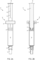
Fig. 2A is a front view of the controlled delivery syringe device ofFig. 1A in accordance with an embodiment of the present invention; -
Fig. 2B is a cross-sectional view of the controlled delivery syringe device ofFig. 2A in accordance with an embodiment of the present invention; -
Fig. 2C is an enlarged view of a counter member of the controlled delivery syringe device ofFig. 2B in accordance with an embodiment of the present invention; -
Fig. 3A is a right side view of the controlled delivery syringe device ofFig. 1A in accordance with an embodiment of the present invention; -
Fig. 3B is a cross-sectional view of the controlled delivery syringe device ofFig. 3A in accordance with an embodiment of the present invention; -
Fig. 3C is an enlarged view of a counter member of the controlled delivery syringe device ofFig. 3B in an initial state in accordance with an embodiment of the present invention; -
Fig. 3D is an enlarged view of a counter member of the controlled delivery syringe device ofFig. 3B in a deflected state in accordance with an embodiment of the present invention; -
Fig. 3E is an enlarged view of a counter member of the controlled delivery syringe device ofFig. 3B in a returned state in accordance with an embodiment of the present invention; -
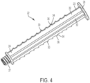
Fig. 4 is a side perspective view of the plunger rod used in the controlled delivery syringe device in accordance with an embodiment of the invention; -
Fig. 5A is a top perspective view of the counter member used in the controlled delivery syringe device in accordance with an embodiment of the invention; and -
Fig. 5B is a bottom perspective view of the counter member used in the controlled delivery syringe device in accordance with an embodiment of the invention. - Corresponding reference characters indicate corresponding parts throughout the several views. The exemplifications set out herein illustrate exemplary embodiments of the disclosure, and such exemplifications are not to be construed as limiting the scope of the disclosure in any manner.
- The following description is provided to enable those skilled in the art to make and use the described embodiments contemplated for carrying out the invention. Various modifications, equivalents, variations, and alternatives, however, will remain readily apparent to those skilled in the art. Any and all such modifications, variations, equivalents, and alternatives are intended to fall within the spirit and scope of the present invention.
- For purposes of the description hereinafter, the terms "upper", "lower", "right", "left", "vertical", "horizontal", "top", "bottom", "lateral", "longitudinal", and derivatives thereof shall relate to the invention as it is oriented in the drawing figures. However, it is to be understood that the invention may assume various alternative variations, except where expressly specified to the contrary. It is also to be understood that the specific devices illustrated in the attached drawings, and described in the following specification, are simply exemplary embodiments of the invention. Hence, specific dimensions and other physical characteristics related to the embodiments disclosed herein are not to be considered as limiting.
- Reference is now made to
Figs. 1A-1B ,2A-2C , and3A-3E , which show a controlled delivery syringe device, generally indicated as 10, in accordance with an embodiment of the present invention. The controlleddelivery syringe device 10 includes asyringe barrel 12 having aproximal end 14 and adistal end 16. The syringe barrel defines achamber 20 configured for containing an injectable material. Thedistal end 16 can include an opening, such as a luer lock opening 18, through which the injectable material can be expelled and aprotective cap 19. It can be appreciated that other types of attachment arrangements can be provided for securing thedistal end 16 of thesyringe barrel 12 for expelling the injectable material into a target location. - With continuing reference to
Figs. 1A-1B and2A-2C and further with reference toFig. 4 , aplunger rod 22 is associated with thesyringe barrel 12. Theplunger rod 22 includes aproximal end 23 and adistal end 24. A plunger orstopper 26 is associated with or secured to thedistal end 24 of theplunger rod 22. According to one embodiment, theplunger rod 22 can be threadedly secured to theplunger 26, as shown by 27 inFig. 2B . It can be appreciated that theplunger rod 22 andplunger 26 can be secured by other techniques known in the art. - The
plunger 26 is axially movable within thesyringe barrel 12 to expel fluid from theopening 18 of thesyringe barrel 12. Theplunger rod 22 can also include athumb press 28 located at theproximal end 23 of theplunger rod 22. A plurality of equally spacedperiodic features 30, such as teeth, are provided on at least a portion of theplunger rod 22. The periodic features orteeth 30 can be located on one side of theplunger rod 22 or alternatively a set of teeth can be located on opposite sides of theplunger rod 22. According to one design, the periodic features orteeth 30 can be notched out of oppositely disposedsplines 32 of theplunger rod 22. - With continuing reference to
Figs. 3A-3E and further with reference toFigs. 5A-5B , a counter member, generally indicated as 40, is engageable with the periodic features orteeth 30. With particular reference toFig. 3C and4 , the periodic features orteeth 30 can be shaped and oriented to cooperate with thecounter member 40 during advancement of the plunger in thesyringe barrel 12 to produce a sudden change in the actuation force, thus, generating a tactile signal upon application of a metered dose. In particular, the periodic feature orteeth 30 can include aflat surface 34 located behind each of theteeth 30 and a tapered orangled portion 36 that extends from theflat surface 34 and tapers downwardly in an inward direction with respect to a longitudinal axis L extending through theplunger rod 22. Thecounter member 40 includes acollar 42 that can be retrofitted and/or permanently attached to theproximal end 14 of thesyringe barrel 12. Thiscollar 42 can overhang the rear opening of thesyringe barrel 12. As shown in the figures, thecollar 42 can be formed of a plurality of interconnecting pieces that can be clamped about therear collar 44 of thesyringe barrel 12. - With continuing reference to
Figs. 3A-3E andFigs. 5A-5B , thecounter member 40 can include either one or a pair oftabs 46 that include anengagement end 47 that interacts or engages with the periodic features orteeth 30. During use of the device, application of the distally direct force to theplunger rod 22 results in disengagement and reengagement of theengagement end 47 of thetabs 46 with sequentially arranged periodic features orteeth 30 on theplunger rod 22. In particular, as shown inFigs. 3C-3E , upon actuation of the actuating member to inject a dose of the injectable material, the engagement ends 47 of thetabs 46 are deflected from an initial state, as shown inFig. 3C , in an outward direction with respect to theteeth 30 and the longitudinal axis L of theplunger rod 22, to a deflected state, as shown inFig. 3D , wherein the engagement ends 47 of thetabs 46 slide along the tapered or angledsurface 36 of theteeth 30 essentially pushing theengagement end 47 in an outward direction out of the way allowing theplunger rod 22 andplunger 26 to advance in the distal direction to administer a dose of injectable material, and finally to a returned state, as shown inFig. 3E . Upon reaching the returned state, the engagement ends 47 of the tabs become reengaged with theteeth 30 to lock theplunger rod 22 andplunger 26 in place. This sudden change in actuation force is perceived by the medical practitioner, thus, providing tactile feedback of dose progression of the injectable material. Thetabs 46 are configured such that they automatically lock onto theteeth 30 when in an unbiased or non-actuated state. According to one example, the tactile feedback occurring from theengagement end 47 of thetab 46 deflecting over thetoothed plunger rod 22 was measured and it was found that for approximately every 5 mm of displacement, a noticeable increase and decrease in force of about 1 N was measured when theteeth 30 passed theengagement end 47 of the deflectingtab 46. - The
plunger rod 22 can include thethumb press 28 located at theproximal end 23 of theplunger rod 22 for receiving the distally directed force applied by the medical practitioner resulting in the disengagement and reengagement of thetabs 46 of thecounter member 40 with sequentially spaced periodic features orteeth 30 on theplunger rod 22. - An actuating member can be provided that includes the at least one
tab 46, which is associated with thecounter member 40. In particular, the at least one tab ortabs 46 can include finger press ends 48. In order to release the engagement ends 47 of thetabs 46 from theteeth 30, a squeezing force can be applied to the finger press ends 48 of thetab 46, causing the engagement ends 47 to pivot in an outward direction, resulting in disengagement and reengagement of the counter member with sequentially spaced periodic features orteeth 30 on theplunger rod 22. The actuating member enables the technician to retract the plunger during administration of the injectable material. Thetabs 46 are configured such that they can be squeezed out of the way when desired, but automatically lock onto theplunger rod teeth 30 when they are not being squeezed. - In accordance with one embodiment, the geometry of the
tab 46 is such that the deflection of thetab 46 when advancing theplunger rod 22 is maximized for a given actuation force. According to yet another embodiment, the geometry of thetab 46 can include a vertical reinforcing member (not shown), to stiffen thetab 46 to withstand pressure from a dialysis line. - An advantage of this invention is that it allows the medical practitioner to count the number of times a "click" is felt during the administration of the injectable material. Since the spacing between the "clicks" is equivalent to a prescribed volume, the practitioner will readily know how much volume has been injected without looking at the graduations on the
syringe barrel 12. For example, if the spacing between two neighboring periodic features orteeth 30 on theplunger rod 22 correspond to a 0.2 ml volume, the practitioner will know that a volume of 1 ml has been delivered after counting five "clicks". Another advantage of the invention is that it prevents backward travel of theplunger rod 22 before exiting the barrel. For example, during administration into a dialysis extracorporeal blood line, if thesyringe 10 is left unclamped or if the clamp fails, theplunger rod 22 cannot be inadvertently pushed back and out of the barrel. Thus, the risk of catastrophic blood spill events is greatly reduced. - Although the invention has been described in detail for the purpose of illustration based on what is currently considered to be the most practical and preferred embodiments, it is to be understood that such detail is solely for that purpose and that the invention is not limited to the disclosed embodiments, but, on the contrary, is intended to cover modifications and equivalent arrangements that are within the spirit and scope of this description. For example, it is to be understood that the present invention contemplates that, to the extent possible, one or more features of any embodiment can be combined with one or more features of any other embodiment.
-
- Aspect 1. A controlled delivery syringe device comprising:
- a syringe barrel having a proximal end and distal end and defining a chamber therein, the chamber configured for containing an injectable material;
- a plunger rod associated with the syringe barrel;
- a plunger secured to the plunger rod and axially movable within the syringe barrel;
- a plurality of equally and sequentially spaced periodic features associated with at least a portion of the plunger rod; and
- a counter member engageable with the periodic features,
- wherein application of a distally directed force to the plunger rod results in disengagement and reengagement of the counter member with the sequentially spaced periodic features on the plunger rod, enabling advancement of the plunger rod and plunger in the syringe barrel while providing tactile feedback of dose progression of the injectable material.
- Aspect 2. The device of Aspect 1, wherein the plunger rod includes a thumb press located at a proximal end of the plunger rod to receive the application of the distally directed force to the plunger rod and wherein the periodic features are tapered to apply an outwardly directed force to the counter member resulting in disengagement and reengagement of the counter member with the sequentially spaced periodic feature on the plunger rod.
- Aspect 3. The device of Aspect 1, further including an actuating member comprising at least one tab having an engagement end and a finger press end and wherein application of a pivoting force to the at least one tab results in disengagement and reengagement of the counter member with the sequentially spaced periodic feature on the plunger rod enabling retraction of the plunger rod and plunger within the syringe barrel.
- Aspect 4. The device of Aspect 3, wherein the counter member comprises the engagement end of the at least one tab and wherein the engagement end engages the periodic features.
- Aspect 5. The device of Aspect 1, wherein the periodic features are provided on oppositely disposed sides of the plunger rod.
- Aspect 6. The device of Aspect 5, wherein the counter member comprises a pair of oppositely disposed tabs, each of the tabs including an engagement end and a finger press end and wherein the engagement end engages the periodic features.
- Aspect 7. The device of Aspect 6, wherein the oppositely disposed tabs are configured to pivot upon the application of a squeezing force to the finger press ends of the tabs, causing the engagement end of the tabs to disengage from the periodic features, enabling retraction or advancement of the plunger rod and plunger in the syringe barrel.
- Aspect 8. The device of Aspect 1, wherein the counter member comprises a collar configured for clamping about a distal end of the syringe barrel.
- Aspect 9. The device of Aspect 8, wherein the collar of the counter member comprises a plurality of separable components capable of being permanently secured about a flange of the syringe barrel, such that the collar of the counter member overhangs a rear opening of the syringe barrel.
-
Aspect 10. The device of Aspect 1, wherein the periodic features are configured to prevent inadvertent removal of the plunger rod out of the syringe barrel. - Aspect 11. A method of retrofitting a syringe with a device for injecting a metered dose of injectable material comprising:
- providing a syringe barrel having a proximal end and distal end defining a chamber therein, the chamber configured for containing an injectable material;
- providing a plunger rod having a proximal end and a distal end and a plunger secured to the distal end thereof, the plunger rod further including a plurality of equally and sequentially spaced periodic features located thereon;
- associating the plunger rod and plunger with the syringe barrel such that the plunger is axially movable within the syringe barrel; and
- securing a counter member onto a distal end of the syringe barrel, the counter member including at least one tab associated with the periodic features on the plunger rod,
- wherein application of a distally directed force to the plunger rod results in disengagement and reengagement of the counter member with a sequentially spaced periodic feature on the plunger rod, enabling advancement of the plunger rod and plunger in the syringe barrel while providing tactile feedback of dose progression of the injectable material.
-
Aspect 12. The method of Aspect 11, wherein the plunger rod includes a thumb press located at a proximal end of the plunger rod to receive application of the distally directed force to the plunger road and wherein the periodic features are tapered to apply an outwardly directed force to the counter member resulting in disengagement and reengagement of the counter member with the sequentially spaced periodic features on the plunger rod. - Aspect 13. The method of Aspect 11, further including an actuating member comprising at least one tab having an engagement end and a finger press end and wherein application of a pivoting force to the at least one tab results in disengagement and reengagement of the counter member with the sequentially spaced periodic features on the plunger rod enabling retraction of the plunger rod and plunger within the syringe barrel.
-
Aspect 14. The method of Aspect 11, wherein the periodic features are provided on oppositely disposed sides of the plunger rod and the counter member comprises a pair of oppositely disposed tabs, each of the tabs including an engagement end and a finger press end and wherein the engagement end engages the periodic features. - Aspect 15. The method of Aspect 11, wherein the oppositely disposed tabs are configured to pivot upon the application of a squeezing force to the finger press ends of the tabs, causing the engagement end of the tabs to disengage from the periodic features, enabling retraction of the plunger rod and plunger in the syringe barrel.
-
Aspect 16. The method of Aspect 11, wherein the counter member comprises a collar configured for clamping about a distal end of the syringe barrel. - Aspect 17. The method of
Aspect 16, wherein the collar of the counter member comprises a plurality of separable components and wherein the method of retrofitting the syringe includes permanently securing the separable components about a flange of the syringe barrel, such that the collar of the counter member overhangs a rear opening of the syringe barrel.
Claims (3)
- A counter member (40) engageable with a plunger rod (22), the plunger rod (22) configured to associate with a syringe barrel (12) and the plunger rod (22) comprising a plurality of equally and sequentially spaced periodic features (30) associated with at least a portion of the plunger rod (22),
characterized by:the counter member (40) comprising a pair of oppositely disposed tabs (46), each of the tabs (46) including an engagement end (47) and a finger press end (48) and wherein the engagement end (47) engages the periodic features (30),wherein the periodic features (30) are provided on oppositely disposed sides of the plunger rod (22), andwherein each of the tabs (46) is configured to pivot upon the application of a squeezing force to the finger press end (48) of each of the tabs (46), causing the engagement end (47) of each of the tabs (46) to disengage from the periodic features (30), enabling retraction or advancement of the plunger rod (22) in the syringe barrel (12). - The counter member (40) of claim 1, further comprising: a collar (42) configured for clamping about a proximal end (14) of the syringe barrel (12).
- The counter member (40) of claim 2, wherein the collar (42) of the counter member (40) comprises a plurality of separable components capable of being permanently secured about a flange of the syringe barrel, such that the collar (42) of the counter member (40) overhangs a rear opening of the syringe barrel (12).
Applications Claiming Priority (3)
| Application Number | Priority Date | Filing Date | Title |
|---|---|---|---|
| US201762485056P | 2017-04-13 | 2017-04-13 | |
| EP18720498.7A EP3609559B1 (en) | 2017-04-13 | 2018-04-05 | Controlled delivery syringe device |
| PCT/US2018/026222 WO2018191101A1 (en) | 2017-04-13 | 2018-04-05 | Controlled delivery syringe device |
Related Parent Applications (1)
| Application Number | Title | Priority Date | Filing Date |
|---|---|---|---|
| EP18720498.7A Division EP3609559B1 (en) | 2017-04-13 | 2018-04-05 | Controlled delivery syringe device |
Publications (2)
| Publication Number | Publication Date |
|---|---|
| EP4129366A1 true EP4129366A1 (en) | 2023-02-08 |
| EP4129366B1 EP4129366B1 (en) | 2024-03-27 |
Family
ID=62063232
Family Applications (2)
| Application Number | Title | Priority Date | Filing Date |
|---|---|---|---|
| EP18720498.7A Active EP3609559B1 (en) | 2017-04-13 | 2018-04-05 | Controlled delivery syringe device |
| EP22190390.9A Active EP4129366B1 (en) | 2017-04-13 | 2018-04-05 | Controlled delivery syringe device |
Family Applications Before (1)
| Application Number | Title | Priority Date | Filing Date |
|---|---|---|---|
| EP18720498.7A Active EP3609559B1 (en) | 2017-04-13 | 2018-04-05 | Controlled delivery syringe device |
Country Status (5)
| Country | Link |
|---|---|
| US (1) | US11628258B2 (en) |
| EP (2) | EP3609559B1 (en) |
| CN (1) | CN110709122B (en) |
| SG (1) | SG11201909548RA (en) |
| WO (1) | WO2018191101A1 (en) |
Families Citing this family (3)
| Publication number | Priority date | Publication date | Assignee | Title |
|---|---|---|---|---|
| USD834182S1 (en) * | 2017-06-20 | 2018-11-20 | Genesis Cosmetics LLC | Syringe |
| CN113853227A (en) * | 2019-04-09 | 2021-12-28 | 和谐医疗解决方案有限责任公司 | Injection device |
| CN113509613B (en) * | 2021-06-08 | 2023-08-15 | 珠海丽笙医疗科技有限公司 | Application method of ring handle syringe |
Citations (6)
| Publication number | Priority date | Publication date | Assignee | Title |
|---|---|---|---|---|
| US4466426A (en) * | 1981-06-29 | 1984-08-21 | Blackman Seymour N | Syringe with actinic ray blocking stripe |
| US20130197449A1 (en) * | 2008-05-15 | 2013-08-01 | Allergan, Inc. | Dosing injector |
| US20140276588A1 (en) * | 2013-03-14 | 2014-09-18 | Boston Scientific Scimed, Inc. | Injection devices with controllable depth adjustability and methods of use |
| US8939959B2 (en) | 2008-01-30 | 2015-01-27 | Becton, Dickinson And Company | Dose dividing delivery device |
| US20160144122A1 (en) * | 2014-11-26 | 2016-05-26 | Fisher Clinical Services GmbH | Syringe Assembly with Plunger Rod Backstop and Method of Use |
| EP3072547A1 (en) * | 2015-03-25 | 2016-09-28 | Q-Med AB | Track-indexed syringe |
Family Cites Families (12)
| Publication number | Priority date | Publication date | Assignee | Title |
|---|---|---|---|---|
| JPS6130699U (en) * | 1984-07-26 | 1986-02-24 | 三菱鉛筆株式会社 | syringe |
| US4915695A (en) * | 1988-09-12 | 1990-04-10 | Koobs David C | Multiple barrel syringe |
| US7611495B1 (en) * | 2005-10-07 | 2009-11-03 | Gianturco Michael C | Device for manually controlling delivery rate of a hypodermic syringe and syringe having same |
| KR101542281B1 (en) * | 2008-06-17 | 2015-08-12 | 덴키 가가쿠 고교 가부시기가이샤 | Injector |
| NO2373362T3 (en) * | 2008-12-04 | 2018-03-10 | ||
| US20110046559A1 (en) * | 2009-08-21 | 2011-02-24 | Becton Dickinson France S.A.S. | Syringe Assembly Having a Flexible or Slidable Flange |
| WO2012133067A1 (en) * | 2011-03-29 | 2012-10-04 | テルモ株式会社 | Syringe |
| CN103945879B (en) * | 2011-09-09 | 2017-08-25 | 默克专利股份公司 | The automatic injector that can be reloaded |
| MX365722B (en) * | 2013-01-30 | 2019-06-11 | Terrence Armstrong Sean | Syringe. |
| US20140350516A1 (en) * | 2013-05-23 | 2014-11-27 | Allergan, Inc. | Mechanical syringe accessory |
| AU2015209535B2 (en) * | 2014-01-21 | 2017-06-01 | Parenteral Technologies, Llc | Force actuated injection device |
| US10532163B2 (en) | 2016-07-02 | 2020-01-14 | Gennady Kleyman | Fluid dispensing device |
-
2018
- 2018-04-05 CN CN201880036409.5A patent/CN110709122B/en active Active
- 2018-04-05 EP EP18720498.7A patent/EP3609559B1/en active Active
- 2018-04-05 US US16/604,396 patent/US11628258B2/en active Active
- 2018-04-05 EP EP22190390.9A patent/EP4129366B1/en active Active
- 2018-04-05 SG SG11201909548R patent/SG11201909548RA/en unknown
- 2018-04-05 WO PCT/US2018/026222 patent/WO2018191101A1/en unknown
Patent Citations (6)
| Publication number | Priority date | Publication date | Assignee | Title |
|---|---|---|---|---|
| US4466426A (en) * | 1981-06-29 | 1984-08-21 | Blackman Seymour N | Syringe with actinic ray blocking stripe |
| US8939959B2 (en) | 2008-01-30 | 2015-01-27 | Becton, Dickinson And Company | Dose dividing delivery device |
| US20130197449A1 (en) * | 2008-05-15 | 2013-08-01 | Allergan, Inc. | Dosing injector |
| US20140276588A1 (en) * | 2013-03-14 | 2014-09-18 | Boston Scientific Scimed, Inc. | Injection devices with controllable depth adjustability and methods of use |
| US20160144122A1 (en) * | 2014-11-26 | 2016-05-26 | Fisher Clinical Services GmbH | Syringe Assembly with Plunger Rod Backstop and Method of Use |
| EP3072547A1 (en) * | 2015-03-25 | 2016-09-28 | Q-Med AB | Track-indexed syringe |
Also Published As
| Publication number | Publication date |
|---|---|
| EP3609559A1 (en) | 2020-02-19 |
| EP3609559B1 (en) | 2022-08-17 |
| US11628258B2 (en) | 2023-04-18 |
| EP4129366B1 (en) | 2024-03-27 |
| WO2018191101A1 (en) | 2018-10-18 |
| SG11201909548RA (en) | 2019-11-28 |
| CN110709122A (en) | 2020-01-17 |
| CN110709122B (en) | 2023-04-11 |
| US20200121857A1 (en) | 2020-04-23 |
Similar Documents
| Publication | Publication Date | Title |
|---|---|---|
| EP3142728B1 (en) | Dosing device for delivery of fluid medicament from a cartridge having a telescoping rod for displacing the piston | |
| JP6223945B2 (en) | Drug delivery equipment | |
| EP2063939B1 (en) | Needle protection device with a blocked protection position | |
| EP4129366B1 (en) | Controlled delivery syringe device | |
| EP2755702B1 (en) | Plunger rod with dose setting means and injection device | |
| EP3068472B1 (en) | Access device | |
| CN107073199B (en) | Automatic injection device for variable dose of medication | |
| DE102004004310A1 (en) | Injection device with lockable dosing member | |
| US20170080159A1 (en) | Medication Delivery Device | |
| CN111372631B (en) | Connector for aseptically transferring fluids | |
| JP2023021444A (en) | Syringe plunger stopper for high dose accuracy drug delivery | |
| JP7432097B2 (en) | Ultra-low-dose waste needle and syringe system that automatically and passively provides needle safety during the injection process | |
| US11471615B2 (en) | Device for assisting subcutaneous injections | |
| EP3254714B1 (en) | Device and system for dispensing a fluid under aseptic conditions | |
| US20200405974A1 (en) | Ultra-Low Waste Disposable Syringe with Self-Adjusting Integrated Safety Features | |
| EP3436109B1 (en) | Plunger slack syringe | |
| AU2007202204B2 (en) | Locking device for connecting housing sections of an administration appliance | |
| JP2022509364A (en) | Pre-filled safety needle and syringe system | |
| DE102014006323A1 (en) | Pre-filled syringe with reuse protection |
Legal Events
| Date | Code | Title | Description |
|---|---|---|---|
| PUAI | Public reference made under article 153(3) epc to a published international application that has entered the european phase |
Free format text: ORIGINAL CODE: 0009012 |
|
| STAA | Information on the status of an ep patent application or granted ep patent |
Free format text: STATUS: THE APPLICATION HAS BEEN PUBLISHED |
|
| AC | Divisional application: reference to earlier application |
Ref document number: 3609559 Country of ref document: EP Kind code of ref document: P |
|
| AK | Designated contracting states |
Kind code of ref document: A1 Designated state(s): AL AT BE BG CH CY CZ DE DK EE ES FI FR GB GR HR HU IE IS IT LI LT LU LV MC MK MT NL NO PL PT RO RS SE SI SK SM TR |
|
| STAA | Information on the status of an ep patent application or granted ep patent |
Free format text: STATUS: REQUEST FOR EXAMINATION WAS MADE |
|
| 17P | Request for examination filed |
Effective date: 20230726 |
|
| RBV | Designated contracting states (corrected) |
Designated state(s): AL AT BE BG CH CY CZ DE DK EE ES FI FR GB GR HR HU IE IS IT LI LT LU LV MC MK MT NL NO PL PT RO RS SE SI SK SM TR |
|
| GRAP | Despatch of communication of intention to grant a patent |
Free format text: ORIGINAL CODE: EPIDOSNIGR1 |
|
| STAA | Information on the status of an ep patent application or granted ep patent |
Free format text: STATUS: GRANT OF PATENT IS INTENDED |
|
| INTG | Intention to grant announced |
Effective date: 20231113 |
|
| GRAS | Grant fee paid |
Free format text: ORIGINAL CODE: EPIDOSNIGR3 |
|
| GRAA | (expected) grant |
Free format text: ORIGINAL CODE: 0009210 |
|
| STAA | Information on the status of an ep patent application or granted ep patent |
Free format text: STATUS: THE PATENT HAS BEEN GRANTED |
|
| AC | Divisional application: reference to earlier application |
Ref document number: 3609559 Country of ref document: EP Kind code of ref document: P |
|
| AK | Designated contracting states |
Kind code of ref document: B1 Designated state(s): AL AT BE BG CH CY CZ DE DK EE ES FI FR GB GR HR HU IE IS IT LI LT LU LV MC MK MT NL NO PL PT RO RS SE SI SK SM TR |
|
| REG | Reference to a national code |
Ref country code: GB Ref legal event code: FG4D |
|
| REG | Reference to a national code |
Ref country code: CH Ref legal event code: EP |