EP4129245A1 - Medical device delivery devices, systems, and methods - Google Patents
Medical device delivery devices, systems, and methods Download PDFInfo
- Publication number
- EP4129245A1 EP4129245A1 EP22184425.1A EP22184425A EP4129245A1 EP 4129245 A1 EP4129245 A1 EP 4129245A1 EP 22184425 A EP22184425 A EP 22184425A EP 4129245 A1 EP4129245 A1 EP 4129245A1
- Authority
- EP
- European Patent Office
- Prior art keywords
- cross
- elongated shaft
- sectional dimension
- aperture
- proximal
- Prior art date
- Legal status (The legal status is an assumption and is not a legal conclusion. Google has not performed a legal analysis and makes no representation as to the accuracy of the status listed.)
- Pending
Links
Images


Classifications
-
- A—HUMAN NECESSITIES
- A61—MEDICAL OR VETERINARY SCIENCE; HYGIENE
- A61F—FILTERS IMPLANTABLE INTO BLOOD VESSELS; PROSTHESES; DEVICES PROVIDING PATENCY TO, OR PREVENTING COLLAPSING OF, TUBULAR STRUCTURES OF THE BODY, e.g. STENTS; ORTHOPAEDIC, NURSING OR CONTRACEPTIVE DEVICES; FOMENTATION; TREATMENT OR PROTECTION OF EYES OR EARS; BANDAGES, DRESSINGS OR ABSORBENT PADS; FIRST-AID KITS
- A61F2/00—Filters implantable into blood vessels; Prostheses, i.e. artificial substitutes or replacements for parts of the body; Appliances for connecting them with the body; Devices providing patency to, or preventing collapsing of, tubular structures of the body, e.g. stents
- A61F2/95—Instruments specially adapted for placement or removal of stents or stent-grafts
- A61F2/962—Instruments specially adapted for placement or removal of stents or stent-grafts having an outer sleeve
- A61F2/966—Instruments specially adapted for placement or removal of stents or stent-grafts having an outer sleeve with relative longitudinal movement between outer sleeve and prosthesis, e.g. using a push rod
-
- A—HUMAN NECESSITIES
- A61—MEDICAL OR VETERINARY SCIENCE; HYGIENE
- A61F—FILTERS IMPLANTABLE INTO BLOOD VESSELS; PROSTHESES; DEVICES PROVIDING PATENCY TO, OR PREVENTING COLLAPSING OF, TUBULAR STRUCTURES OF THE BODY, e.g. STENTS; ORTHOPAEDIC, NURSING OR CONTRACEPTIVE DEVICES; FOMENTATION; TREATMENT OR PROTECTION OF EYES OR EARS; BANDAGES, DRESSINGS OR ABSORBENT PADS; FIRST-AID KITS
- A61F2/00—Filters implantable into blood vessels; Prostheses, i.e. artificial substitutes or replacements for parts of the body; Appliances for connecting them with the body; Devices providing patency to, or preventing collapsing of, tubular structures of the body, e.g. stents
- A61F2/95—Instruments specially adapted for placement or removal of stents or stent-grafts
-
- A—HUMAN NECESSITIES
- A61—MEDICAL OR VETERINARY SCIENCE; HYGIENE
- A61F—FILTERS IMPLANTABLE INTO BLOOD VESSELS; PROSTHESES; DEVICES PROVIDING PATENCY TO, OR PREVENTING COLLAPSING OF, TUBULAR STRUCTURES OF THE BODY, e.g. STENTS; ORTHOPAEDIC, NURSING OR CONTRACEPTIVE DEVICES; FOMENTATION; TREATMENT OR PROTECTION OF EYES OR EARS; BANDAGES, DRESSINGS OR ABSORBENT PADS; FIRST-AID KITS
- A61F2/00—Filters implantable into blood vessels; Prostheses, i.e. artificial substitutes or replacements for parts of the body; Appliances for connecting them with the body; Devices providing patency to, or preventing collapsing of, tubular structures of the body, e.g. stents
- A61F2/82—Devices providing patency to, or preventing collapsing of, tubular structures of the body, e.g. stents
- A61F2/86—Stents in a form characterised by the wire-like elements; Stents in the form characterised by a net-like or mesh-like structure
- A61F2/90—Stents in a form characterised by the wire-like elements; Stents in the form characterised by a net-like or mesh-like structure characterised by a net-like or mesh-like structure
-
- A—HUMAN NECESSITIES
- A61—MEDICAL OR VETERINARY SCIENCE; HYGIENE
- A61F—FILTERS IMPLANTABLE INTO BLOOD VESSELS; PROSTHESES; DEVICES PROVIDING PATENCY TO, OR PREVENTING COLLAPSING OF, TUBULAR STRUCTURES OF THE BODY, e.g. STENTS; ORTHOPAEDIC, NURSING OR CONTRACEPTIVE DEVICES; FOMENTATION; TREATMENT OR PROTECTION OF EYES OR EARS; BANDAGES, DRESSINGS OR ABSORBENT PADS; FIRST-AID KITS
- A61F2/00—Filters implantable into blood vessels; Prostheses, i.e. artificial substitutes or replacements for parts of the body; Appliances for connecting them with the body; Devices providing patency to, or preventing collapsing of, tubular structures of the body, e.g. stents
- A61F2/95—Instruments specially adapted for placement or removal of stents or stent-grafts
- A61F2/9517—Instruments specially adapted for placement or removal of stents or stent-grafts handle assemblies therefor
-
- A—HUMAN NECESSITIES
- A61—MEDICAL OR VETERINARY SCIENCE; HYGIENE
- A61F—FILTERS IMPLANTABLE INTO BLOOD VESSELS; PROSTHESES; DEVICES PROVIDING PATENCY TO, OR PREVENTING COLLAPSING OF, TUBULAR STRUCTURES OF THE BODY, e.g. STENTS; ORTHOPAEDIC, NURSING OR CONTRACEPTIVE DEVICES; FOMENTATION; TREATMENT OR PROTECTION OF EYES OR EARS; BANDAGES, DRESSINGS OR ABSORBENT PADS; FIRST-AID KITS
- A61F2/00—Filters implantable into blood vessels; Prostheses, i.e. artificial substitutes or replacements for parts of the body; Appliances for connecting them with the body; Devices providing patency to, or preventing collapsing of, tubular structures of the body, e.g. stents
- A61F2/95—Instruments specially adapted for placement or removal of stents or stent-grafts
- A61F2/9522—Means for mounting a stent or stent-graft onto or into a placement instrument
-
- A—HUMAN NECESSITIES
- A61—MEDICAL OR VETERINARY SCIENCE; HYGIENE
- A61F—FILTERS IMPLANTABLE INTO BLOOD VESSELS; PROSTHESES; DEVICES PROVIDING PATENCY TO, OR PREVENTING COLLAPSING OF, TUBULAR STRUCTURES OF THE BODY, e.g. STENTS; ORTHOPAEDIC, NURSING OR CONTRACEPTIVE DEVICES; FOMENTATION; TREATMENT OR PROTECTION OF EYES OR EARS; BANDAGES, DRESSINGS OR ABSORBENT PADS; FIRST-AID KITS
- A61F2/00—Filters implantable into blood vessels; Prostheses, i.e. artificial substitutes or replacements for parts of the body; Appliances for connecting them with the body; Devices providing patency to, or preventing collapsing of, tubular structures of the body, e.g. stents
- A61F2/82—Devices providing patency to, or preventing collapsing of, tubular structures of the body, e.g. stents
- A61F2002/823—Stents, different from stent-grafts, adapted to cover an aneurysm
-
- A—HUMAN NECESSITIES
- A61—MEDICAL OR VETERINARY SCIENCE; HYGIENE
- A61F—FILTERS IMPLANTABLE INTO BLOOD VESSELS; PROSTHESES; DEVICES PROVIDING PATENCY TO, OR PREVENTING COLLAPSING OF, TUBULAR STRUCTURES OF THE BODY, e.g. STENTS; ORTHOPAEDIC, NURSING OR CONTRACEPTIVE DEVICES; FOMENTATION; TREATMENT OR PROTECTION OF EYES OR EARS; BANDAGES, DRESSINGS OR ABSORBENT PADS; FIRST-AID KITS
- A61F2/00—Filters implantable into blood vessels; Prostheses, i.e. artificial substitutes or replacements for parts of the body; Appliances for connecting them with the body; Devices providing patency to, or preventing collapsing of, tubular structures of the body, e.g. stents
- A61F2/95—Instruments specially adapted for placement or removal of stents or stent-grafts
- A61F2002/9505—Instruments specially adapted for placement or removal of stents or stent-grafts having retaining means other than an outer sleeve, e.g. male-female connector between stent and instrument
-
- A—HUMAN NECESSITIES
- A61—MEDICAL OR VETERINARY SCIENCE; HYGIENE
- A61F—FILTERS IMPLANTABLE INTO BLOOD VESSELS; PROSTHESES; DEVICES PROVIDING PATENCY TO, OR PREVENTING COLLAPSING OF, TUBULAR STRUCTURES OF THE BODY, e.g. STENTS; ORTHOPAEDIC, NURSING OR CONTRACEPTIVE DEVICES; FOMENTATION; TREATMENT OR PROTECTION OF EYES OR EARS; BANDAGES, DRESSINGS OR ABSORBENT PADS; FIRST-AID KITS
- A61F2250/00—Special features of prostheses classified in groups A61F2/00 - A61F2/26 or A61F2/82 or A61F9/00 or A61F11/00 or subgroups thereof
- A61F2250/0004—Special features of prostheses classified in groups A61F2/00 - A61F2/26 or A61F2/82 or A61F9/00 or A61F11/00 or subgroups thereof adjustable
- A61F2250/0008—Special features of prostheses classified in groups A61F2/00 - A61F2/26 or A61F2/82 or A61F9/00 or A61F11/00 or subgroups thereof adjustable for adjusting a position by translation along an axis or two perpendicular axes
Definitions
- the present technology relates to medical device delivery devices, systems, and methods.
- Walls of the vasculature may develop areas of pathological dilatation called aneurysms that often have thin, weak walls that are prone to rupturing.
- Aneurysms are generally caused by weakening of the vessel wall due to disease, injury, or a congenital abnormality. Aneurysms occur in different parts of the body, and the most common are abdominal aortic aneurysms and cerebral (e.g., brain) aneurysms in the neurovasculature. When the weakened wall of an aneurysm ruptures, it can result in death, especially if it is a cerebral aneurysm that ruptures.
- Aneurysms are generally treated by excluding or at least partially isolating the weakened part of the vessel from the arterial circulation.
- conventional aneurysm treatments include: (i) surgical clipping, where a metal clip is secured around the base of the aneurysm; (ii) packing the aneurysm with small, flexible wire coils (micro-coils); (iii) using embolic materials to "fill" an aneurysm; (iv) using detachable balloons or coils to occlude the parent vessel that supplies the aneurysm; and (v) intravascular stenting.
- Intravascular stents are well known in the medical arts for the treatment of vascular stenoses or aneurysms.
- Stents are prostheses that expand radially or otherwise within a vessel or lumen to support the vessel from collapsing. Methods for delivering these intravascular stents are also well known.
- Conventional methods of introducing a compressed stent into a vessel and positioning it within an area of stenosis or an aneurysm include percutaneously advancing a distal portion of a guiding catheter through the vascular system of a patient until the distal portion is proximate the stenosis or aneurysm.
- a second, inner catheter is advanced through the distal region of the guiding catheter.
- a stent delivery system is then advanced out of the distal region of the guiding catheter into the vessel until the distal portion of the delivery system carrying the compressed stent is positioned at the point of the lesion within the vessel.
- the compressed stent is then released and expanded so that it supports the vessel at the point of the lesion.
- Conventional stent delivery systems can include a core member that assists with deploying a stent at a treatment site.
- the core member can be a multi-component assembly that includes a proximal portion in the form of a wire that can be gripped by a clinician, a middle portion in the form of a hypotube with flexibility enhancing cuts configured to extend through the patient's vasculature, and a distal portion in the form of a wire distally extending from a distal end of the hypotube.
- the stent can be positioned over the distal wire, where the stent can engage with the core member via one or more stent engagement members that are coupled to the distal wire.
- the distal wire To ensure the stent is reliably and accurately deployed at the treatment site, the distal wire must be properly connected within the core member.
- the distal wire is typically connected within the core member by being soldered or welded to the hypotube.
- the connection between the wire and the hypotube can fail.
- the distal wire can become disconnected from the hypotube and be left untethered from the rest of the delivery system while inside a blood vessel.
- the present technology relates to medical delivery devices, systems, and methods configured to address the above-noted limitations of existing stent delivery systems as well as other issues.
- Some embodiments of the present technology are directed to a medical device delivery system comprising a joining element that can provide a stronger and more reliable connection between the wire and the hypotube within the core member.
- the joining element can be welded to an end of the hypotube and can interlock with the wire. This arrangement moves the solder location of the distal wire away from the interior of the hypotube and provides an interference fit for the distal wire instead of a soldered joint. As a result of this arrangement, the hypotube and distal wire within a core member are less susceptible to connection failures.
- a medical device delivery system can include an elongated tubular member having a distal end portion, a proximal end portion, and a lumen extending therethrough and a joining element coupled to a distal end portion of the elongated tubular member.
- the joining element can include a bumper having a distal end portion configured to engage a proximal portion of a medical device and a proximal portion adjacent the distal end portion of the elongated tubular member, wherein the proximal portion defines a slot having a length along a first direction.
- the joining element can also include an aperture extending through the bumper, the aperture having a first cross-sectional dimension along a second direction and a second cross-sectional dimension along a third direction different from the second direction, the first cross-sectional dimension being greater than the second cross-sectional dimension, wherein the first direction is about orthogonal to the second direction.
- the medical device delivery system can also include an elongated shaft having a distal region and a flattened region proximal of the distal region, the flattened region having a greatest cross-sectional dimension that is smaller than the first cross-sectional dimension of the aperture but larger than the second cross-sectional dimension of the aperture, wherein the flattened region is at least partially received within the slot.
- a core assembly for a medical device delivery system can include an elongated tubular member having a distal end portion, a proximal end portion, and a lumen extending therethrough, and a joining element coupled to the distal end portion of the tubular member.
- the joining element can include: a bumper having a proximal face abutting the distal end portion of the elongated tubular member; a proximal portion extending proximal of the proximal face and into the lumen of the elongated tubular member; and an aperture extending through the bumper and the proximal portion, the aperture having a first cross-sectional dimension along a first radial axis and a second cross-sectional dimension along a second radial axis, the first cross-sectional dimension being greater than the second cross-sectional dimension.
- the core assembly can further include an elongated shaft coupled to the joining element.
- the elongated shaft can include: an intermediate portion extending distal to the bumper portion and configured to receive a medical device thereover; a proximal portion extending through the joining element aperture; and an engagement feature disposed along the proximal portion, the engagement feature having a first radially outermost dimension along a first radial direction and a second radially outermost dimension along a second radial direction, the first radially outermost dimension being smaller than the first cross-sectional dimension and the second-cross sectional dimension of the aperture, the second radially outermost dimension being smaller than the first cross-sectional dimension of the aperture but larger than the second cross-sectional dimension of the aperture.
- a medical device delivery system can include a hypotube having a proximal portion, a distal portion, and a lumen extending therethrough and a joining element positioned at the distal portion of the hypotube.
- the joining element can include: a bumper portion having a proximal-facing surface abutting a distal end of the hypotube; a proximal portion extending proximally from the distal portion such that the proximal portion is positioned within the lumen of the hypotube; and an aperture extending through the bumper and proximal portions, wherein the aperture has a first cross-sectional dimension along a first radial direction and a second cross-sectional dimension along a second radial direction, the second cross-sectional dimension being smaller than the first cross-sectional dimension.
- the medical device delivery system can also include an elongated member having a proximally located attachment portion including a retention region extending through the aperture and a widened region extending laterally away from a longitudinal axis of the elongate member to a greater extent than the retention region, wherein the widened region is configured to fit through the aperture in a first orientation and to collide with the bumper and the proximal portions in a second orientation.
- a medical device delivery system in one embodiment, can include an elongated tubular member having a distal end portion, a proximal end portion, and a lumen extending therethrough, and a joining element coupled to a distal end portion of the elongated tubular member.
- the joining element can include: a bumper having a distal end portion configured to engage a proximal portion of a medical device and a proximal portion adjacent the distal end portion of the elongated tubular member; a nose having a body extending between a proximal end portion and a distal end portion, the proximal end portion of the nose being adjacent the distal end portion of the bumper; and an aperture extending through the bumper, the aperture having a first cross-sectional dimension along a first direction and a second cross-sectional dimension along a second direction different from the first direction, the first cross-sectional dimension being greater than the second cross-sectional dimension.
- the medical device delivery system can also include an elongated shaft having a distal region and a flattened region proximal of the distal region, the flattened region having a greatest cross-sectional dimension that is smaller than the first cross-sectional dimension but larger than the second cross-sectional dimension.
- a method of assembling a medical device delivery system can include coupling a bumper to a distal end portion of an elongated tubular member.
- the bumper can include: a body having a proximal face abutting the distal end portion of the elongated tubular member and a distal face configured to abut a proximal portion of a medical device; a proximal portion extending proximal of the proximal face and into a lumen of the elongated tubular member, the proximal portion having a slot with a length along a first radial axis; and a aperture extending through the body and the proximal portion, the aperture having a first cross-sectional dimension along a second radial axis and a second cross-sectional dimension along a third radial axis, the first cross-sectional dimension being greater than the second cross-sectional dimension.
- the method can also include orienting an elongated shaft with the aperture.
- the elongated shaft can have an engagement feature disposed along a proximal portion of the elongated shaft, the engagement feature having a first radially outermost dimension along a first radial direction and a second radially outermost dimension along a second radial direction.
- Orienting the elongated shaft with the aperture can include aligning the second radial direction with the second radial axis.
- the method can also include moving the engagement feature of the elongated shaft distally through the first aperture; aligning the second radial direction with the first radial axis; and moving the engagement feature of the elongated shaft proximally until the engagement feature is received within the slot of the proximal portion of the bumper.
- a medical device delivery system comprising:
- Clause 2 The medical device delivery system of Clause 1 or 2, wherein, when the flattened region is received within the slot, the flattened region prevents or limits distal movement of the elongated shaft with respect to the joining element.
- Clause 3 The medical device delivery system of any one of Clauses 1 to 3, the joining element further comprising a nose positioned over the elongated shaft and distal of the bumper.
- Clause 4 The medical device delivery system of Clause 3, wherein the nose is coupled to the elongated shaft.
- Clause 5 The medical device delivery system of any one of Clauses 1 to 4, wherein the elongated shaft is at least one of a wire, hypotube, or coil.
- a core assembly for a medical device delivery system comprising:
- Clause 7 The core assembly of Clause 6, wherein the proximal portion of the joining element comprises a slot configured to receive the engagement feature.
- Clause 8 The core assembly of Clause 6 or 7, wherein the elongated shaft is substantially cylindrical, and wherein the engagement feature comprises a region of the elongated shaft that has been flattened.
- Clause 9 The core assembly of any one of Clauses 6 to 8, wherein the first radial axis is substantially perpendicular to the second radial axis.
- Clause 10 The core assembly of any one of Clauses 6 to 9, wherein a distal face of bumper is configured to abut a proximal end of the medical device.
- Clause 11 The core assembly of any one of Clauses 6 to 10, wherein the elongated tubular member is a hypotube having one or more flexibility-enhancing cuts along its length.
- Clause 12 The core assembly of any one of Clauses 6 to 11, wherein the elongated shaft is a wire.
- Clause 13 The core assembly of any one of Clauses 6 to 12, wherein the medical device is a stent.
- Clause 14 The core assembly of any one of Clauses 6 to 13, wherein the medical device is a tubular braided implant.
- a medical device delivery system comprising:
- Clause 16 The medical device delivery system of Clause 15, wherein a distal face of bumper portion is configured to abut a proximal end of a medical device.
- Clause 17 The medical device delivery system of Clauses 15 or 16, wherein the widened region engages the proximal portion of the joining element and limits distal movement of the elongated member relative to the joining element.
- Clause 18 The medical device delivery system of any one of Clauses 15 to 17, wherein the proximal portion of the joining element comprises a slot having a length along a third radial direction.
- Clause 19 The medical device delivery system of Clause 18, wherein the widened region is configured to be received within the slot.
- Clause 20 The medical device delivery system of Clauses 18 or 19, wherein the first radial direction is substantially perpendicular to the third radial direction.
- Clause 21 The medical device delivery system of any one of Clauses 15 to 20, wherein the elongated member is at least one of a wire, hypotube, or coil.
- a medical device delivery system comprising:
- Clause 23 The medical device delivery system of Clause 22, wherein the proximal portion comprises a slot having a length along a third direction.
- Clause 24 The medical device delivery system of Clause 23, wherein the flattened region is configured to be received within the slot.
- Clause 25 The medical device delivery system of Clause 24, wherein, when the flattened region is received within the slot, the flattened region prevents or limits distal movement of the elongated shaft with respect to the joining element.
- Clause 26 The medical device delivery system of any one of Clauses 22 to 25, wherein the nose is coupled to the elongated shaft.
- Clause 27 The medical device delivery system of Clause 26 wherein coupling the nose to the elongated shaft comprises soldering the nose to the elongated shaft.
- Clause 28 The medical device delivery system of any one of Clauses 22 to 27, wherein the aperture is a first aperture, the joining element further comprising a second aperture extending through the nose and aligning with the first aperture.
- Clause 29 The medical device delivery system of any one of Clauses 22 to 28, wherein the elongated shaft is at least one of a wire, hypotube, or coil.
- a method of assembling a medical device delivery system comprising: coupling a bumper to a distal end portion of an elongated tubular member, the bumper comprising:
- Clause 31 The method of Clause 30, further comprising coupling a nose with the elongated shaft, the nose being coupled with the elongated shaft at a location that is distal to the distal face of the body of the bumper.
- Clause 32 The method of Clauses 30 or 31, wherein the first radially outermost dimension of the engagement feature is smaller than the first cross-sectional dimension and the second-cross sectional dimension of the aperture, and wherein the second radially outermost dimension of the engagement feature is smaller than the first cross-sectional dimension of the aperture but larger than the second cross-sectional dimension of the aperture.
- Clause 33 The method of any one of Clauses 30 to 32, wherein the first radial axis is substantially perpendicular to the second radial axis.
- Clause 34 The method of any one of Clauses 30 to 33, wherein the first radial axis is substantially parallel to the third radial axis.
- distal and proximal define a position or direction with respect to a clinician or a clinician's control device (e.g., a handle of a delivery catheter).
- a clinician's control device e.g., a handle of a delivery catheter.
- distal and distal refer to a position distant from or in a direction away from a clinician or a clinician's control device along the length of device.
- proximal and proximally refer to a position near or in a direction toward a clinician or a clinician's control device along the length of device.
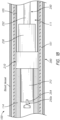
- FIG. 1A is a schematic illustration of a medical device delivery system 100 ("system 100") configured in accordance with one or more embodiments of the present technology.
- FIG. 1B is a partial schematic view of the medical device delivery system of FIG. 1A within a blood vessel.
- This system 100 may be used to deliver and/or deploy a medical device, such as but not limited to a stent, into a hollow anatomical structure, such as a blood vessel.
- the stent can comprise a braided stent or other form of stent such as a woven stent, knit stent, laser-cut stent, roll-up stent, etc.
- the stent can optionally be configured to act as a "flow diverter” device for treatment of aneurysms, such as those found in blood vessels including arteries in the brain or within the cranium, or in other locations in the body such as peripheral arteries.
- the stent can optionally be similar to any of the versions or sizes of the PIPELINE TM Embolization Device marketed by Medtronic Neurovascular of Irvine, California USA.
- the stent can alternatively comprise any suitable tubular medical device and/or other features, as described herein.
- the stent can be any one of the stents described in U.S. Application No. 15/892,268, filed February 8, 2018 , titled VASCULAR EXPANDABLE DEVICES, the entirety of which is hereby incorporated by reference herein and made a part of this specification.
- the system 100 can comprise a core member or core assembly 102 configured to extend generally longitudinally through the lumen 111 of an elongate catheter 101.
- the core member 102 can have a proximal region 104 and a distal region 106, which can optionally include a tip coil 108.
- the core member 102 can also comprise an intermediate portion 110 located between the proximal region 104 and the distal region 106.
- the intermediate portion 110 is the portion of the core member 102 onto or over which the stent 105 extends when the core member 102 is in the pre-deployment configuration as shown in FIG. 1A .
- the delivery system 100 can include and/or be used with any number of catheters 101.
- the catheter can optionally comprise any of the various lengths of the MARKSMAN TM catheter available from Medtronic Neurovascular of Irvine, California USA.
- the catheter can optionally comprise a microcatheter having an inner diameter of about 0.030 inches or less, and/or an outer diameter of 3 French or less near the distal region.
- the catheter can comprise a microcatheter which is configured to access the internal carotid artery, or another location within the neurovasculature distal of the internal carotid artery.
- the core member 102 can generally comprise any member(s) with sufficient flexibility and column strength to move the stent 105 or other medical device through a surrounding catheter 101.
- the core member 102 can therefore comprise a wire, tube (e.g., hypotube), braid, coil, or other suitable member(s), or a combination of wire(s), tube(s), braid(s), coil(s), etc.
- the embodiment of the core member 102 depicted in FIG. 1A is of multi-member construction, comprising a wire 112 with a tube 114 surrounding the wire 112 along at least a portion of its length. For example, a distal portion of the wire 112 can be positioned within the tube 114 so that the tube 114 surrounds the distal portion of the wire 112.
- An outer layer of lubricious material such as PTFE (polytetrafluoroethylene or TEFLON TM ) or other lubricious polymers, can cover some or all of the tube 114 and/or wire 112.
- the wire 112 may taper or vary in diameter along some or all of its length.
- the wire 112 may include one or more fluorosafe markers (not shown), and such marker(s) can be located on a portion of the wire 112 that is not covered by the outer layer of lubricious material (e.g., proximal of the outer layer). This portion of the wire 112 marked by the marker(s), and/or proximal of any outer layer, can comprise a bare metal outer surface.
- the core member 102 can comprise a stent coupling assembly 120 and/or a distal interface assembly 122 that can interconnect the stent 105 with the core member 102.
- a joining element 200 couples the stent coupling assembly 120 and/or distal interface assembly 122 with the core member 102.
- the joining element 200 can couple with the tube 114.
- the joining element 200 can be welded to a distal end portion of the tube 114.
- the joining element 200 can be interlocked with an elongated shaft 250 that extends through the intermediate portion 110 and distal region 106 of the core member 102.
- the stent coupling assembly 120 can be coupled with the elongated shaft 250 within the intermediate portion 110 so that the stent coupling assembly 120 engages the stent 105.
- the distal interface assembly 122 can be coupled with the elongated shaft 250 distal to the stent 105 so that the distal interface assembly 122 engages with a distal portion of the stent 105.
- the stent coupling assembly 120 can comprise one or more engagement members 123a, 123b (collectively “engagement members 123”) that may underlie and mechanically engage or interlock with the stent 105. In this manner, the stent coupling assembly 120 cooperates with an overlying inner surface of a surrounding catheter 101 to engage the stent 105 such that the stent coupling assembly 120 can move the stent 105 along and within the catheter 101, e.g., as the user pushes the core member 102 distally and/or pulls the core member 102 proximally relative to the catheter 101, resulting in a corresponding distal and/or proximal movement of the stent 105 within the elongate shaft lumen 111.
- the stent coupling assembly 120 can include one or more restraints 121 that are fixed to the core member 102 (e.g., to the elongated shaft 250 thereof in the depicted embodiment) so as to be immovable relative to the core member 102, either in a longitudinal/sliding manner or a radial/rotational manner.
- the stent coupling assembly 120 can also include a plurality of engagement members 123 separated by one or more spacers 125.
- the stent coupling assembly 120 can include a first engagement member 123a and a second engagement member 123b separated by a spacer 125.
- the engagement members 123 and/or the spacers 125 can be coupled to (e.g., mounted on) the core member 102 so that the stent coupling assembly 120 can rotate about the longitudinal axis of the core member 102 (e.g., of the intermediate portion 110), and/or move or slide longitudinally along the core member 102.
- the engagement members 123 and the spacer 125 can be coupled to the elongated shaft 250 so that the engagement members 123 and the spacer 125 can rotate about the elongated shaft 250.
- the stent 105 can be moved distally or proximally within an overlying catheter 101 via the stent coupling assembly 120.
- the stent 105 can be resheathed via the stent coupling assembly 120 after partial deployment of the stent 105 from a distal opening of the catheter 101.
- the distal interface assembly 122 can comprise a distal cover 126.
- the distal cover 126 can take the form of, for example, a distal engagement member, a distal device cover, or distal stent cover.
- the distal cover 126 can be configured to reduce friction between the stent 105 (e.g., a distal portion thereof) and the inner surface of a surrounding catheter 101.
- the distal cover 126 can be configured as a lubricious, flexible structure having a free first end or section 126a that can extend over at least a portion of the stent 105 and/or intermediate portion 110 of the core member 202, and a fixed second end or section 126b that can be coupled (directly or indirectly) to the core member 102.
- the distal cover 126 is rotatably coupled to the core member 102.
- the distal cover 126 can have a first (e.g., delivery) position, configuration, or orientation in which the distal cover 126 can extend proximally from the second section 126b or its (direct or indirect) attachment to the core member 102, and at least partially surround or cover a distal portion of the stent 105.
- the distal cover 226 can be movable from the first orientation to a second (e.g., resheathing) position, configuration, or orientation (not shown) in which the distal cover can be everted such that the first end 126a of the distal cover is positioned distally relative to the second end 126b of the distal cover 126 to enable the resheathing of the core member 102, either with the stent 105 carried thereby, or without the stent 105.
- a second e.g., resheathing position, configuration, or orientation (not shown) in which the distal cover can be everted such that the first end 126a of the distal cover is positioned distally relative to the second end 126b of the distal cover 126 to enable the resheathing of the core member 102, either with the stent 105 carried thereby, or without the stent 105.
- the distal interface assembly can include a proximal and distal restraint 127, 128.
- One or both of the proximal and distal restraints 127, 128 can have an outside diameter or other radially outermost dimension that is smaller than the (e.g., pre-deployment) outside diameter or other radially outermost dimension of the distal cover 126, so that one or both of the restraints 127, 128 will tend not to bear against or contact the inner surface of the catheter 101 during operation of the core member 102.
- the outer diameters of the restraints 127 and 128 can be made larger than the largest radial dimension of the pre-deployment distal cover 126, and/or make the outer diameter of the proximal restraint 127 larger than the outer diameter of the distal restraint 128. This configuration allows easy and smooth retrieval of the distal cover 126 and the restraints 127, 128 back into the elongate shaft post stent deployment.
- the distal cover 126, the proximal restraint 127, and the distal restraint 128 can be coupled to (e.g., mounted on) the core member 102 so distal interface assembly can rotate about the longitudinal axis of the core member 102.
- the stent 105 can be rotatable with respect to the core member 102 about the longitudinal axis thereof, by virtue of the rotatable connections of the stent coupling assembly 120 and distal cover 126.
- the stent 105, stent coupling assembly 120 and distal cover 126 can rotate together in this manner about the core member 102.
- the core member 102 can be advanced more easily through tortuous vessels as the tendency of the vessels to twist the stent 105 and/or core member 102 is negated by the rotation of the stent 105, stent coupling assembly 120, and distal cover 126 about the core member 102.
- the required push force or delivery force is reduced, as the user's input push force is not diverted into torsion of the stent 105 and/or core member 102.
- a twisted stent 105 and/or core member 102 to untwist suddenly or "whip" upon exiting tortuosity or deployment of the stent 105, and the tendency of a twisted stent to resist expansion upon deployment, are also reduced or eliminated.
- the user can "steer" the core member 102 via the tip coil 108, particularly if the coil 108 is bent at an angle in its unstressed configuration.
- Such a coil tip can be rotated about a longitudinal axis of the system 100 relative to the stent 105, coupling assembly 120 and/or distal cover 126 by rotating the distal region 106 of the core member 102.
- the user can point the coil tip 108 in the desired direction of travel of the core member 102, and upon advancement of the core member the tip will guide the core member in the chosen direction.
- the joining element 200 can include a bumper portion or bumper 210, a proximal portion 212 proximal to the bumper 210, and a nose portion or nose 230 distal of the bumper 210.
- the elongated shaft 250 can extend through a lumen of the joining element 200 and extend distally to the nose portion 230. As discussed in more detail below, the elongated shaft 250 can mechanically interlock with the proximal portion 212 of the joining element 200, thereby securing the elongated shaft 250 in position relative to the joining element 200.
- the stent engagement members 123, spacer 125, and distal restraint 121 can be mounted over the elongated shaft 250 at a position distal to the joining element 200.
- the stent 105 can be disposed over the stent engagement members 123 with a proximal end of the stent 105 abutting the distal face of the bumper 210.
- the nose portion 230 can extend partially into a lumen of the stent 105.
- the bumper 210 can have an outer diameter that is slightly smaller than the inner diameter of the catheter 101, leaving a radial gap between an outer edge of the bumper 210 and the inner wall of the catheter 101.
- the nose 230 can have a diameter that is slightly smaller than an inner diameter of a compressed stent 105, allowing for the nose 230 to be positioned within a lumen formed by the stent 105.
- the joining element 200 can be coupled with the tube 114.
- the joining element 200 can couple to a distal end portion of the tube 114 so that the bumper 210 is axially disposed between the tube 114 and the stent 105.
- the distal end portion of the tube 114 can be welded, soldered, and/or otherwise joined to a proximal face 220 of the bumper 210 while the stent 105 is disposed distal to a distal face 222 of the bumper 210.
- the proximal portion 212 of the bumper 210 can be disposed within a lumen formed by the tube 114.
- the joining element 200 is configured to abut the proximal end or proximal edge of the stent 105.
- the bumper 210 can be positioned adjacent the stent 105 so that the bumper 210 abuts the proximal end of the stent 105.
- the joining element 200 can couple with the elongated shaft 250.
- the elongated shaft 250 can interlock with the proximal portion 212 of the joining element 200 and extend through the joining element 200.
- the elongated shaft 250 can be coupled with the nose 230 of the joining element 200.
- the elongated shaft 250 can be welded, soldered, and/or otherwise joined with the nose 230.
- a portion of the elongated shaft 250 that is distal to the bumper 210 can be configured to receive a medical device such as a stent thereover.
- the stent coupling assembly 120 can couple to the elongated shaft 250 at a position that is distal to the bumper 210, with the stent coupling assembly 120 configured to engage the stent 105 over this portion of the elongated shaft 250.
- the elongated shaft 250 can include a widened region 254 that interlocks with the proximal portion 212 of the joining element 200.
- the joining element 200 can retain the elongated shaft 250 and prevent the elongated shaft 250 from moving distally relative to the core member 102.
- the nose 230 can be coupled with the elongated shaft 250 in a manner that prevents the elongated shaft 250 from moving proximally relative to the core member 102.
- the nose 230 can be welded, soldered, and/or otherwise joined with the elongated shaft 250 so that the elongated shaft 250 cannot be moved proximally relative to the core member 102.
- the mechanical interlock at the proximal portion 212 of the joining element 200 and the solder joint at the nose 230 of the joining element 200 can prevent any axial movement of the elongated shaft 250 relative to the joining element 200 and/or the tube 114.
- the bumper 210 and the nose 230 can prevent any rotational movement of the elongated shaft 250 relative to the joining element 200 and/or the tube 114.
- coupling the elongated shaft 250 with the joining element 200 can render the elongated shaft 250 immovable relative to the joining element 200 and/or the tube 114, as the joining element 200 can retain the elongated shaft 250 in place axially and rotationally.
- the joining element 200 can be used to move (e.g., push) the stent 105 distally through the catheter 101.
- the distal face 222 of the bumper 210 can press against the stent 105 and move the stent 105 distally within the catheter 101.
- the joining element 200 can be configured to transmit some, most, or all of a distally directed axial (e.g., push) force to the stent 105, wholly or partially in place of the engagement members 123.
- the engagement members 123 can be configured to transmit little or no push force to the stent 105 while the stent 105 is delivered distally along the length of the catheter 101.
- this can reduce or eliminate a tendency of the engagement members 123 to distort the pores of the stent 105 with which the engagement members 123 are engaged when the engagement members 123 are employed to transmit force to and move the stent 105 within the catheter 101.
- Use of the joining element 200 to move the stent 105 in this manner can also reduce or eliminate axial movement of the stent 105 relative to the core member 102 that sometimes accompanies the pore distortion.
- the vast majority of the travel of the stent 105 within the catheter 101 is in the distal or "push” direction during delivery to the treatment location, in contrast to the relatively short travel involved in resheathing the stent 105, in the proximal or "pull” direction, prior to an eventual final deployment of the stent. Therefore, configuring the joining element 200 to transmit most or all of the push force to the stent 105 can significantly reduce or substantially eliminate such distortion and/or relative axial movement of the stent.
- FIG. 2A illustrates a schematic view of the bumper 210 in accordance with one or more embodiments of the present technology.
- FIG. 2B illustrates an end view of the bumper 210 from FIG. 2A .
- the bumper 210 can include a generally cylindrical body 214 disposed at the distal end of the proximal portion 212.
- the proximal portion 212 can be separate distinct from the bumper 210, in some embodiments the proximal portion 212 and the bumper 210 can be integrally formed and/or combined into the same component.
- the bumper 210 can define the proximal portion 212 and can include a slot 218 (described below) configured to mechanically interlock with the elongated shaft 250.
- the proximal portion 212 forms a cylindrical body that extends proximally from the proximal face 220 of the bumper 210.
- the width of the proximal portion 212 is smaller than an inner diameter of the tube 114, allowing for the proximal portion 212 to be received within the tube 114.
- the body 214 of the bumper 210 can have a generally a cylindrical shape that is wider (e.g., having a greater radially outermost dimension) than the proximal portion 212 and can have a width that is slightly smaller than the inner diameter of the catheter 101, leaving a radial gap between an outer edge of the body 214 and the inner wall of the catheter 101.
- the bumper 210 can define both the proximal face 220 and a distal face 222.
- An aperture 216 can be formed through the bumper 210 and the proximal portion 212.
- the aperture 216 can form an irregular shaped lumen throughout the bumper 210 and the proximal portion 212.
- one portion of the aperture 216 can form a rectangular or slot profile while a second portion of the aperture 216 can form a circular or ellipsoid profile.
- These separate portions of the aperture can define one or more cross-sectional dimensions of different lengths.
- the slot portion can define a first cross-sectional dimension that has a length 224a and the circular portion can define a second cross-sectional dimension that has a length 224b.
- the length 224a can be larger than the length 224b.
- the aperture 216 can define two radial axes or directions. For example, as illustrated in FIG. 2B , the aperture 216 defines a first radial axis A1 along the rectangular profile and a second radial axis A2 along the circular profile.
- a slot 218 can be formed at the proximal end of the proximal portion 212.
- the slot 218 can form a channel within the proximal portion 212 that insects with the aperture 216.
- the slot 218 can have a length that is formed at an angle with respect to the axis A1.
- the slot 218 can be perpendicular to the axis A1.
- the slot 218 can have a length that is parallel to the axis A2.
- the bumper 210 and the proximal portion 212 can couple with the elongated shaft 250.
- the aperture 216 and can be sized so that the elongated shaft 250 can be received within the aperture 216.
- the widened region 254 of the elongated shaft 250 can be positioned within slot 218. Positioning the widened region 254 within the slot 218 interlocks the elongated shaft 250 with the joining element 200 and prevents the elongated shaft 250 from moving distally and/or rotationally relative to the joining element 200.
- FIG. 3A illustrates a schematic view of the elongated shaft 250 in accordance with one or more embodiments of the present technology.
- FIG. 3B illustrates an end view of the elongated shaft 250 of FIG. 3A .
- the elongated shaft 250 can include a body 252 and a widened region 254.
- the body 252 can extend along an axis L and define a proximal portion 250a and a distal portion 250b.
- the widened region 254 can be formed in the body 252.
- the widened region 254 can be a flattened or "coined" region of the body 252 that forms a cylindrical profile which is normal to a cylindrical profile formed by the body 252.
- body 252 forms a cylindrical profile having a height along the axis L while the widened region 254 forms a cylindrical profile having a height along a radial direction R2, with the radial direction R2 being normal to the axis L.
- This profile of the widened region 254 results in the widened region 254 having cross-sectional dimension that is greater than a cross-sectional dimension of the body 252 along one direction but less than a cross-sectional dimension the body 252 along a separate direction.
- the greatest cross-section dimension of the widened region 254 is greater than greatest cross-section dimension of the body 252 along a radial direction R1 but smaller than greatest cross-section dimension of the body 252 along the radial direction R2.
- the widened region 254 can be radially wider than the body 252 along one direction but having substantially the same radial dimension as the body 252 along another direction.
- the widened region 254 can include one or more projections (e.g., ridges, bumps, projections, etc.) that project radially outward from the surface of the body 252 at the widened region 254.
- the elongated shaft 250 can be sized so that the elongated shaft 250 can be received within the aperture 216.
- the body 252 of the elongated shaft 250 can have a diameter that is smaller than the length 224b of the aperture 216 while the widened region 254 can have a diameter that is smaller than the length 224a of the aperture 216.
- both the body 252 and the widened region 254 of the elongated shaft 250 can be received within the aperture 216 of the bumper 210 or proximal portion 212.
- the elongated shaft 250 can be received within the aperture 216 when the elongated shaft 250 is in a specific orientation.
- the widened region 254 can have a diameter that is greater than the length 224b, preventing the widened region 254 from moving through the bumper 210 or proximal portion 212 when the radial direction R1 aligns with the axis A2, but allowing the widened region 254 to move through the bumper 210 or proximal portion 212 when the radial direction R1 aligns with the axis A1.
- the widened region 254 can be positioned within the slot 218.
- the slot 218 can be sized to form a friction fit with widened region 254.
- the widened region 254 of the elongated shaft 250 can be formed by crimping or crushing a portion of the elongated shaft 250.
- a press can press into a portion of the elongated shaft 250, forming the widened region 254.
- the widened region 254 can be formed at any suitable location along the length of the elongated shaft 250, including at a proximalmost end of the shaft 250 or at a region spaced apart from the proximalmost end.
- the widened region 254 can take the form of an engagement feature.
- the engagement feature can define a first radially outermost dimension along the radial direction R2 and a second radially outermost dimension along the second radial direction R1.
- the first radially outermost dimension is smaller than the length 224a of the first cross-sectional dimension and the length 224b of the second-cross sectional dimension.
- the second radially outermost dimension is smaller than the length 224a of the first cross-sectional dimension but larger than the length 224b of the second cross-sectional dimension. This configuration allows for the widened region 254 to be moved through the aperture 216 when the widened region 254 is aligned with second cross-sectional dimension (e.g., when the radial direction R1 aligns with the axis A1).
- the widened region 254 of the elongated shaft 250 can take the form of an attachment portion and the portion of the elongated shaft 250 extending through the bumper 210 can take the form of a retention region.
- the attachment portion of the elongated shaft 250 can extend laterally away from an axis L of the elongated shaft 250 to a greater extent than the retention region of the elongated shaft 250.
- the attachment portion is configured to fit through the aperture 216 in a first orientation and to collide with the bumper 210 or proximal portion 212 in a second orientation.
- the attachment portion when the attachment portion is aligned with the larger portion of the aperture 216, the attachment portion can fit within the aperture 216, but when the attachment portion is not aligned with the larger portion of the aperture 216, the attachment portion will collide with the distal face 222 of the bumper 210 or the proximal face of the proximal portion 212.
- FIG. 4A illustrates an isometric view of the nose 230 in accordance with one or more embodiments of the present technology
- FIG 4B illustrates a view of a proximal face 236 of the nose 230
- the nose 230 can have a body 232 with an aperture 234 extending through the body 232.
- the body 232 can form a cylindrical profile with a proximal face 236 at a first end and a distal face 238 at a second end opposite the first.
- the diameter or width of the body 232 can be less than the diameter or width of the stent 105, allowing for the nose 230 to be positioned within the lumen of the stent 105 without contacting the stent 105.
- the nose 230 can be positioned distal of the bumper 210.
- the proximal face 236 of the nose 230 can contact the distal face 222 of the bumper 210.
- the nose 230 can be coupled to the bumper 210.
- the nose 230 can be welded, soldered, or otherwise joined to the bumper 210.
- the nose 230 can be coupled with the elongated shaft 250. At least a portion of the elongated shaft 250 can be disposed within the aperture 234 of the nose 230. While disposed within the aperture 234, the elongated shaft can be welded, soldered, or otherwise joined with the nose 230. In some embodiments, the aperture 216 can align with the aperture 234.
- the axial movement of the elongated shaft 250 can be limited or prevented.
- the elongated shaft 250 can be prevented from moving proximally relative to the core member 102, as the nose 230 would collide with the bumper 210, stopping the elongated shaft 250 from moving proximally.
- the nose 230 can prevent the elongated shaft 250 from rotating relative to the core member 102.
- the coupling the nose 230 with the bumper 210 and the elongated shaft 250 can stop any rotational movement of the elongated shaft 250 relative to the core member 102.
- coupling the nose 230 with the bumper 210 and the elongated shaft 250 can prevent any axial movement of the elongated shaft 250 relative to the core member 102.
- a fixed connection between the nose 230, bumper 210, and elongated shaft 250 can render the elongated shaft 250 immovable relative to the core member 102.
- FIGS. 5A-5E illustrate several schematic views of interlocking the elongated shaft 250 with the joining element 200, in accordance with one or more embodiments of the present technology.
- FIG. 5A illustrates the elongated shaft 250 being inserted into the aperture 216 of the bumper 210 and
- FIG. 5A1 shows a cross-sectional view of FIG. 5A along the 5A1 line within FIG. 5A .
- the elongated shaft 250 is inserted into the aperture 216 of the bumper 210 at the distal face 222 of the bumper 210.
- the elongated shaft 250 can be inserted into the proximal face of the proximal portion 212.
- the widened region 254 While being inserted into the bumper 210 the widened region 254 is oriented so that the radial direction R1 of the elongated shaft 250 aligns with the axis A1 of the aperture 216. This orientation allows for the widened region 254 to inserted into the aperture 216 without the bumper 210 impeding its movement, as illustrated in FIG. 5A1 .
- FIG. 5B illustrates the elongated shaft 250 being received in the aperture 216 of the bumper 210 and proximal portion 212 with the widened region 254 being positioned proximal of the proximal portion 212.
- the elongated shaft 250 can be proximally pushed through the aperture 216 until the widened region 254 is positioned proximally of the proximal portion 212. In this position, the widened region 254 can be spaced apart from the bumper 210, allowing for the elongated shaft 250 to be rotated freely and relative to the bumper 210.
- FIG. 5C illustrates the elongated shaft 250 being reoriented after the widened region 254 is positioned proximal of the proximal portion 212.
- the elongated shaft 250 can be aligned with the slot 218.
- the slot 218 can be formed at an angle with respect the axis A1. Accordingly, to align the widened region 254 with the slot 218, the widened region is rotated so that the radial direction R1 aligns with the length of slot 218.
- Aligning the widened region 254 with the slot 218 prevents the elongated shaft 250 from being axially moved through the joining element 200, as the widened region 254 will collide with proximal portion 212 and impede any movement through the aperture 216.
- FIG. 5D illustrates the elongated shaft 250 interlocked with the proximal portion 212 and FIG. 5D1 shows a cross-sectional view of FIG. 5D along the 5D1 line within FIG. 5D .
- the elongated shaft 250 With the widened region 254 being received within the slot 218, the elongated shaft 250 is prevented from moving further distally relative to the proximal portion 212, as the widened region 254 of the elongated shaft 250 is unable to move through the aperture 216 while positioned within the slot 218. Additionally, or alternatively, when the widened region 254 is received within the slot 218, the elongated shaft 250 is prevented from rotating relative to the joining element 200, as the fit between the widened region 254 and slot 218 prevents any substantial rotational movement of the elongated shaft 250 independent from the bumper 210. In some embodiments, the elongated shaft 250 can later be adjusted axially and/or rotationally after the elongated shaft 250 is moved proximally out of the slot 218.
- FIG. 5E illustrates the nose 230 being coupled with the elongated shaft 250 after the elongated shaft 250 is interlocked with the bumper 210.
- the nose 230 can be slid over the elongated shaft 250 until the proximal portion of the nose 230 contacts the distal face 222 of the bumper 210. Once the nose 230 contacts the bumper 210, the nose 230 can be coupled to the elongated shaft 250 by welding, soldering, or otherwise joining the nose 230 and the elongated shaft 250 together.
- the elongated shaft 250 is prevented from moving proximally relative to the joining element 200, as the contact between the nose 230 and the bumper 210 would impede the elongated shaft 250 and prevent the elongated shaft 250 from moving proximally independent of the joining element 200.
- the nose 230 can be coupled to the bumper 210 by welding, soldering, and/or otherwise joining the nose 230 with the bumper 210. By coupling the nose 230 to the bumper 210 and the elongated shaft 250, the elongated shaft 250 can be prevented from rotating independently of the joining element 200.
- the bumper 210 is coupled to core member 102.
- the bumper 210 is coupled to the core member 102 by welding, soldering, and/or otherwise joining the bumper 210 to the tube 114.
- the distal end portion of the tube 114 can be welded to the proximal face 220 of the bumper 210 and/or to the proximal portion 212, coupling the bumper 210 with the tube 114.
- the elongated shaft 250 is inserted into the aperture 216 of the bumper 210 through the distal face 222 of the bumper 210.
- inserting the elongated shaft 250 into the aperture 216 can include aligning the radial direction R1 of the elongated shaft 250 with the A1 axis of the aperture 216. With the elongated shaft 250 positioned within the aperture 216, the elongated shaft 250 is then distally moved through the aperture 216 until the widened region 254 is through aperture 216, proximal to the proximal end of the proximal portion 212 and is free to rotate. Next, the elongated shaft 250 can be rotated so the widened region 254 aligns with the slot 218.
- the elongated shaft 250 is moved distally until the widened region 254 is received within the slot 218, interlocking the elongated shaft with the proximal portion 212.
- the nose 230 is slid over the elongated shaft 250 and positioned adjacent the bumper 210 so that the proximal face of the nose 230 contacts the distal face 222 of the bumper 210. With the nose 230 contacting the bumper 210, the nose 230 is coupled to the elongated shaft 250 and the bumper 210.
- the nose 230 can be soldered to the elongated shaft 250 and the bumper 210.
- the bumper 210 is welded to the tube 114 after the widened region 254 is positioned within the slot 218.
- the elongated shaft 250 is initially moved through the proximal portion 212 of the joining element instead of the distal face 222 of the bumper 210.
- the stent 105 can be moved distally or proximally within the catheter 101 via the core member 102 and the stent coupling assembly 120.
- the core member 102 is moved distally while the catheter 101 is held stationary, the core member 102 is held stationary while the catheter 101 is withdrawn proximally, or the core member 102 is moved distally while the catheter 101 is simultaneously withdrawn proximally.
- the joining element 200 bears against the proximal end or edge of the stent 105 and causes the stent 105 to be advanced distally, and ultimately out of the of the catheter 101.
- the mechanical engagement or interlock between the engagement members 123 and the stent 105 in response to the application of a distally directed force to the core member 102, causes the stent 105 to move distally through and out of the catheter 101.
- the relative movement between the core member 102 and the catheter 101 is reversed compared to moving the stent 105 out of the catheter 101 such that the proximal region of the restraint 121 bears against the distal region of the spacer 125 and thereby causes the spacer 125, the release members 124, and the engagement members 123 to be retracted into the lumen 111 of the catheter 101.
- the mechanical engagement between the engagement members 123 and the stent 105 while the engagement members 123 are positioned within the lumen 111 holds the stent 105 with respect to the core member 102 such that proximal movement of the stent 105 relative to the catheter 101 enables re-sheathing of the stent 105 back into the catheter 101.
- This is useful when the stent 105 has been partially deployed and a portion of the stent 105 remains disposed between at least one of the engagement members 123 (e.g.
- the stent 105 can be withdrawn back into the catheter 101 by moving the core member 102 proximally relative to the catheter 101 (and/or moving the catheter 101 distally relative to the core member 102). Resheathing in this manner remains possible until the engagement members 123 and/or catheter 101 have been moved to a point where the first engagement member 123a is beyond the distal opening of the catheter 101 and the stent 105 is released from between the first engagement member 123a and the catheter 101.
Landscapes
- Health & Medical Sciences (AREA)
- Engineering & Computer Science (AREA)
- Biomedical Technology (AREA)
- Cardiology (AREA)
- Oral & Maxillofacial Surgery (AREA)
- Transplantation (AREA)
- Heart & Thoracic Surgery (AREA)
- Vascular Medicine (AREA)
- Life Sciences & Earth Sciences (AREA)
- Animal Behavior & Ethology (AREA)
- General Health & Medical Sciences (AREA)
- Public Health (AREA)
- Veterinary Medicine (AREA)
- Media Introduction/Drainage Providing Device (AREA)
Abstract
A medical device delivery system includes a joining element with a bumper having a distal end portion configured to engage a proximal portion of a medical device and a proximal end portion adjacent a distal end portion of an elongated tubular member. The proximal end portion defines a slot having a length along a first direction. The joining element further includes an aperture extending through the bumper and having a first, greater, cross-sectional dimension along a second direction and a second, smaller, cross-sectional dimension along a third direction. The system can include an elongated shaft having a distal region and a flattened region proximal of the distal region, the flattened region having a greatest cross-sectional dimension that is smaller than the first cross-sectional dimension but larger than the second cross-sectional dimension The flattened region can be received within the slot.
Description
- The present technology relates to medical device delivery devices, systems, and methods.
- Walls of the vasculature, particularly arterial walls, may develop areas of pathological dilatation called aneurysms that often have thin, weak walls that are prone to rupturing. Aneurysms are generally caused by weakening of the vessel wall due to disease, injury, or a congenital abnormality. Aneurysms occur in different parts of the body, and the most common are abdominal aortic aneurysms and cerebral (e.g., brain) aneurysms in the neurovasculature. When the weakened wall of an aneurysm ruptures, it can result in death, especially if it is a cerebral aneurysm that ruptures.
- Aneurysms are generally treated by excluding or at least partially isolating the weakened part of the vessel from the arterial circulation. For example, conventional aneurysm treatments include: (i) surgical clipping, where a metal clip is secured around the base of the aneurysm; (ii) packing the aneurysm with small, flexible wire coils (micro-coils); (iii) using embolic materials to "fill" an aneurysm; (iv) using detachable balloons or coils to occlude the parent vessel that supplies the aneurysm; and (v) intravascular stenting.
- Intravascular stents are well known in the medical arts for the treatment of vascular stenoses or aneurysms. Stents are prostheses that expand radially or otherwise within a vessel or lumen to support the vessel from collapsing. Methods for delivering these intravascular stents are also well known.
- Conventional methods of introducing a compressed stent into a vessel and positioning it within an area of stenosis or an aneurysm include percutaneously advancing a distal portion of a guiding catheter through the vascular system of a patient until the distal portion is proximate the stenosis or aneurysm. A second, inner catheter is advanced through the distal region of the guiding catheter. A stent delivery system is then advanced out of the distal region of the guiding catheter into the vessel until the distal portion of the delivery system carrying the compressed stent is positioned at the point of the lesion within the vessel. The compressed stent is then released and expanded so that it supports the vessel at the point of the lesion.
- Conventional stent delivery systems can include a core member that assists with deploying a stent at a treatment site. The core member can be a multi-component assembly that includes a proximal portion in the form of a wire that can be gripped by a clinician, a middle portion in the form of a hypotube with flexibility enhancing cuts configured to extend through the patient's vasculature, and a distal portion in the form of a wire distally extending from a distal end of the hypotube. The stent can be positioned over the distal wire, where the stent can engage with the core member via one or more stent engagement members that are coupled to the distal wire. To ensure the stent is reliably and accurately deployed at the treatment site, the distal wire must be properly connected within the core member. The distal wire is typically connected within the core member by being soldered or welded to the hypotube. In these conventional stent delivery systems, the connection between the wire and the hypotube can fail. In severe cases, the distal wire can become disconnected from the hypotube and be left untethered from the rest of the delivery system while inside a blood vessel. These and other connection failures have been linked to the presence of flux within an inner diameter of the hypotube.
- The present technology relates to medical delivery devices, systems, and methods configured to address the above-noted limitations of existing stent delivery systems as well as other issues. Some embodiments of the present technology, for example, are directed to a medical device delivery system comprising a joining element that can provide a stronger and more reliable connection between the wire and the hypotube within the core member. The joining element can be welded to an end of the hypotube and can interlock with the wire. This arrangement moves the solder location of the distal wire away from the interior of the hypotube and provides an interference fit for the distal wire instead of a soldered joint. As a result of this arrangement, the hypotube and distal wire within a core member are less susceptible to connection failures.
- Additional features and advantages of the present technology are described below, and in part will be apparent from the description, or may be learned by practice of the present technology. The advantages of the present technology will be realized and attained by the structure particularly pointed out in the written description and claims hereof as well as the appended drawings. The subject technology is illustrated, for example, according to various aspects described below. These are provided as examples and do not limit the subject technology.
- In one embodiment, a medical device delivery system is described. The medical device delivery system can include an elongated tubular member having a distal end portion, a proximal end portion, and a lumen extending therethrough and a joining element coupled to a distal end portion of the elongated tubular member. The joining element can include a bumper having a distal end portion configured to engage a proximal portion of a medical device and a proximal portion adjacent the distal end portion of the elongated tubular member, wherein the proximal portion defines a slot having a length along a first direction. The joining element can also include an aperture extending through the bumper, the aperture having a first cross-sectional dimension along a second direction and a second cross-sectional dimension along a third direction different from the second direction, the first cross-sectional dimension being greater than the second cross-sectional dimension, wherein the first direction is about orthogonal to the second direction. The medical device delivery system can also include an elongated shaft having a distal region and a flattened region proximal of the distal region, the flattened region having a greatest cross-sectional dimension that is smaller than the first cross-sectional dimension of the aperture but larger than the second cross-sectional dimension of the aperture, wherein the flattened region is at least partially received within the slot.
- In one embodiment, a core assembly for a medical device delivery system is described. The core assembly can include an elongated tubular member having a distal end portion, a proximal end portion, and a lumen extending therethrough, and a joining element coupled to the distal end portion of the tubular member. The joining element can include: a bumper having a proximal face abutting the distal end portion of the elongated tubular member; a proximal portion extending proximal of the proximal face and into the lumen of the elongated tubular member; and an aperture extending through the bumper and the proximal portion, the aperture having a first cross-sectional dimension along a first radial axis and a second cross-sectional dimension along a second radial axis, the first cross-sectional dimension being greater than the second cross-sectional dimension. The core assembly can further include an elongated shaft coupled to the joining element. The elongated shaft can include: an intermediate portion extending distal to the bumper portion and configured to receive a medical device thereover; a proximal portion extending through the joining element aperture; and an engagement feature disposed along the proximal portion, the engagement feature having a first radially outermost dimension along a first radial direction and a second radially outermost dimension along a second radial direction, the first radially outermost dimension being smaller than the first cross-sectional dimension and the second-cross sectional dimension of the aperture, the second radially outermost dimension being smaller than the first cross-sectional dimension of the aperture but larger than the second cross-sectional dimension of the aperture.
- In one embodiment, a medical device delivery system is described. The medical device delivery system can include a hypotube having a proximal portion, a distal portion, and a lumen extending therethrough and a joining element positioned at the distal portion of the hypotube. The joining element can include: a bumper portion having a proximal-facing surface abutting a distal end of the hypotube; a proximal portion extending proximally from the distal portion such that the proximal portion is positioned within the lumen of the hypotube; and an aperture extending through the bumper and proximal portions, wherein the aperture has a first cross-sectional dimension along a first radial direction and a second cross-sectional dimension along a second radial direction, the second cross-sectional dimension being smaller than the first cross-sectional dimension. The medical device delivery system can also include an elongated member having a proximally located attachment portion including a retention region extending through the aperture and a widened region extending laterally away from a longitudinal axis of the elongate member to a greater extent than the retention region, wherein the widened region is configured to fit through the aperture in a first orientation and to collide with the bumper and the proximal portions in a second orientation.
- In one embodiment, a medical device delivery system is described. The medical device delivery system can include an elongated tubular member having a distal end portion, a proximal end portion, and a lumen extending therethrough, and a joining element coupled to a distal end portion of the elongated tubular member. The joining element can include: a bumper having a distal end portion configured to engage a proximal portion of a medical device and a proximal portion adjacent the distal end portion of the elongated tubular member; a nose having a body extending between a proximal end portion and a distal end portion, the proximal end portion of the nose being adjacent the distal end portion of the bumper; and an aperture extending through the bumper, the aperture having a first cross-sectional dimension along a first direction and a second cross-sectional dimension along a second direction different from the first direction, the first cross-sectional dimension being greater than the second cross-sectional dimension. The medical device delivery system can also include an elongated shaft having a distal region and a flattened region proximal of the distal region, the flattened region having a greatest cross-sectional dimension that is smaller than the first cross-sectional dimension but larger than the second cross-sectional dimension.
- In one embodiment, a method of assembling a medical device delivery system is described. The method can include coupling a bumper to a distal end portion of an elongated tubular member. The bumper can include: a body having a proximal face abutting the distal end portion of the elongated tubular member and a distal face configured to abut a proximal portion of a medical device; a proximal portion extending proximal of the proximal face and into a lumen of the elongated tubular member, the proximal portion having a slot with a length along a first radial axis; and a aperture extending through the body and the proximal portion, the aperture having a first cross-sectional dimension along a second radial axis and a second cross-sectional dimension along a third radial axis, the first cross-sectional dimension being greater than the second cross-sectional dimension. The method can also include orienting an elongated shaft with the aperture. The elongated shaft can have an engagement feature disposed along a proximal portion of the elongated shaft, the engagement feature having a first radially outermost dimension along a first radial direction and a second radially outermost dimension along a second radial direction. Orienting the elongated shaft with the aperture can include aligning the second radial direction with the second radial axis. The method can also include moving the engagement feature of the elongated shaft distally through the first aperture; aligning the second radial direction with the first radial axis; and moving the engagement feature of the elongated shaft proximally until the engagement feature is received within the slot of the proximal portion of the bumper.
-
Clause 1. A medical device delivery system comprising: - an elongated tubular member having a distal end portion, a proximal end portion, and a lumen extending therethrough;
- a joining element coupled to a distal end portion of the elongated tubular member, the joining element comprising:
- a bumper having a distal end portion configured to engage a proximal portion of a medical device;
- a proximal portion adjacent the distal end portion of the elongated tubular member, wherein the proximal portion defines a slot having a length along a first direction; and
- an aperture extending through the bumper and the proximal portion, the aperture having a first cross-sectional dimension along a second direction and a second cross-sectional dimension along a third direction different from the second direction, the first cross-sectional dimension being greater than the second cross-sectional dimension, wherein the first direction is about orthogonal to the second direction; and
- an elongated shaft having a distal region and a flattened region proximal of the distal region, the flattened region having a greatest cross-sectional dimension that is smaller than the first cross-sectional dimension of the aperture but larger than the second cross-sectional dimension of the aperture, wherein the flattened region is at least partially received within the slot.
- Clause 2. The medical device delivery system of
Clause 1 or 2, wherein, when the flattened region is received within the slot, the flattened region prevents or limits distal movement of the elongated shaft with respect to the joining element. - Clause 3. The medical device delivery system of any one of
Clauses 1 to 3, the joining element further comprising a nose positioned over the elongated shaft and distal of the bumper. - Clause 4. The medical device delivery system of Clause 3, wherein the nose is coupled to the elongated shaft.
- Clause 5. The medical device delivery system of any one of
Clauses 1 to 4, wherein the elongated shaft is at least one of a wire, hypotube, or coil. - Clause 6. A core assembly for a medical device delivery system comprising:
- an elongated tubular member having a distal end portion, a proximal end portion, and a lumen extending therethrough;
- a joining element coupled to the distal end portion of the tubular member, the joining element comprising:
- a bumper having a proximal face abutting the distal end portion of the elongated tubular member;
- a proximal portion extending proximal of the proximal face and into the lumen of the elongated tubular member; and
- an aperture extending through the bumper and the proximal portion, the aperture having a first cross-sectional dimension along a first radial axis and a second cross-sectional dimension along a second radial axis, the first cross-sectional dimension being greater than the second cross-sectional dimension; and
- an elongated shaft coupled to the joining element, the elongated shaft comprising:
- an intermediate portion extending distal to the bumper portion and configured to receive a medical device thereover;
- a proximal portion extending through the joining element aperture; and
- an engagement feature disposed along the proximal portion, the engagement feature having a first radially outermost dimension along a first radial direction and a second radially outermost dimension along a second radial direction, the first radially outermost dimension being smaller than the first cross-sectional dimension and the second-cross sectional dimension of the aperture, the second radially outermost dimension being smaller than the first cross-sectional dimension of the aperture but larger than the second cross-sectional dimension of the aperture.
- Clause 7. The core assembly of Clause 6, wherein the proximal portion of the joining element comprises a slot configured to receive the engagement feature.
- Clause 8. The core assembly of Clause 6 or 7, wherein the elongated shaft is substantially cylindrical, and wherein the engagement feature comprises a region of the elongated shaft that has been flattened.
- Clause 9. The core assembly of any one of Clauses 6 to 8, wherein the first radial axis is substantially perpendicular to the second radial axis.
- Clause 10. The core assembly of any one of Clauses 6 to 9, wherein a distal face of bumper is configured to abut a proximal end of the medical device.
- Clause 11. The core assembly of any one of Clauses 6 to 10, wherein the elongated tubular member is a hypotube having one or more flexibility-enhancing cuts along its length.
- Clause 12. The core assembly of any one of Clauses 6 to 11, wherein the elongated shaft is a wire.
- Clause 13. The core assembly of any one of Clauses 6 to 12, wherein the medical device is a stent.
- Clause 14. The core assembly of any one of Clauses 6 to 13, wherein the medical device is a tubular braided implant.
- Clause 15. A medical device delivery system comprising:
- a hypotube having a proximal portion, a distal portion, and a lumen extending therethrough;
- a joining element positioned at the distal portion of the hypotube, the joining element comprising:
- a bumper portion having a proximal-facing surface abutting a distal end of the hypotube;
- a proximal portion extending proximally from the distal portion such that the proximal portion is positioned within the lumen of the hypotube; and
- an aperture extending through the bumper and proximal portions, wherein the aperture has a first cross-sectional dimension along a first radial direction and a second cross-sectional dimension along a second radial direction, the second cross-sectional dimension being smaller than the first cross-sectional dimension; and
- an elongated member having a proximally located attachment portion including a retention region extending through the aperture and a widened region extending laterally away from a longitudinal axis of the elongate member to a greater extent than the retention region, wherein the widened region is configured to fit through the aperture in a first orientation and to collide with the bumper and the proximal portions in a second orientation.
- Clause 16. The medical device delivery system of Clause 15, wherein a distal face of bumper portion is configured to abut a proximal end of a medical device.
- Clause 17. The medical device delivery system of Clauses 15 or 16, wherein the widened region engages the proximal portion of the joining element and limits distal movement of the elongated member relative to the joining element.
- Clause 18. The medical device delivery system of any one of Clauses 15 to 17, wherein the proximal portion of the joining element comprises a slot having a length along a third radial direction.
- Clause 19. The medical device delivery system of Clause 18, wherein the widened region is configured to be received within the slot.
- Clause 20. The medical device delivery system of Clauses 18 or 19, wherein the first radial direction is substantially perpendicular to the third radial direction.
- Clause 21. The medical device delivery system of any one of Clauses 15 to 20, wherein the elongated member is at least one of a wire, hypotube, or coil.
- Clause 22. A medical device delivery system comprising:
- an elongated tubular member having a distal end portion, a proximal end portion, and a lumen extending therethrough;
- a joining element coupled to a distal end portion of the elongated tubular member, the joining element comprising:
- a bumper having a distal end portion configured to engage a proximal portion of a medical device;
- a proximal portion disposed proximal of the bumper and adjacent the distal end portion of the elongated tubular member;
- a nose having a body extending between a proximal end portion and a distal end portion, the proximal end portion of the nose being adjacent the distal end portion of the bumper; and
- an aperture extending through the bumper, the aperture having a first cross-sectional dimension along a first direction and a second cross-sectional dimension along a second direction different from the first direction, the first cross-sectional dimension being greater than the second cross-sectional dimension; and
- an elongated shaft having a distal region and a flattened region proximal of the distal region, the flattened region having a greatest cross-sectional dimension that is smaller than the first cross-sectional dimension but larger than the second cross-sectional dimension.
- Clause 23. The medical device delivery system of Clause 22, wherein the proximal portion comprises a slot having a length along a third direction.
- Clause 24. The medical device delivery system of Clause 23, wherein the flattened region is configured to be received within the slot.
- Clause 25. The medical device delivery system of Clause 24, wherein, when the flattened region is received within the slot, the flattened region prevents or limits distal movement of the elongated shaft with respect to the joining element.
- Clause 26. The medical device delivery system of any one of Clauses 22 to 25, wherein the nose is coupled to the elongated shaft.
- Clause 27. The medical device delivery system of Clause 26 wherein coupling the nose to the elongated shaft comprises soldering the nose to the elongated shaft.
- Clause 28. The medical device delivery system of any one of Clauses 22 to 27, wherein the aperture is a first aperture, the joining element further comprising a second aperture extending through the nose and aligning with the first aperture.
- Clause 29. The medical device delivery system of any one of Clauses 22 to 28, wherein the elongated shaft is at least one of a wire, hypotube, or coil.
- Clause 30. A method of assembling a medical device delivery system comprising:
coupling a bumper to a distal end portion of an elongated tubular member, the bumper comprising: - a body having a proximal face abutting the distal end portion of the elongated tubular member and a distal face configured to abut a proximal portion of a medical device;
- a proximal portion extending proximal of the proximal face and into a lumen of the elongated tubular member, the proximal portion having a slot with a length along a first radial axis; and
- an aperture extending through the body and the proximal portion, the aperture having a first cross-sectional dimension along a second radial axis and a second cross-sectional dimension along a third radial axis, the first cross-sectional dimension being greater than the second cross-sectional dimension;
- orienting an elongated shaft with the aperture, the elongated shaft having an engagement feature disposed along a proximal portion of the elongated shaft, the engagement feature having a first radially outermost dimension along a first radial direction and a second radially outermost dimension along a second radial direction, wherein orienting the elongated shaft with the aperture comprises aligning the second radial direction with the second radial axis;
- moving the engagement feature of the elongated shaft distally through the first aperture;
- aligning the second radial direction with the first radial axis; and
- moving the engagement feature of the elongated shaft proximally until the engagement feature is received within the slot of the proximal portion of the bumper.
- Clause 31. The method of Clause 30, further comprising coupling a nose with the elongated shaft, the nose being coupled with the elongated shaft at a location that is distal to the distal face of the body of the bumper.
- Clause 32. The method of Clauses 30 or 31, wherein the first radially outermost dimension of the engagement feature is smaller than the first cross-sectional dimension and the second-cross sectional dimension of the aperture, and wherein the second radially outermost dimension of the engagement feature is smaller than the first cross-sectional dimension of the aperture but larger than the second cross-sectional dimension of the aperture.
- Clause 33. The method of any one of Clauses 30 to 32, wherein the first radial axis is substantially perpendicular to the second radial axis.
- Clause 34. The method of any one of Clauses 30 to 33, wherein the first radial axis is substantially parallel to the third radial axis.
- Many aspects of the present disclosure can be better understood with reference to the following drawings. The components in the drawings are not necessarily to scale. Instead, emphasis is placed on illustrating clearly the principles of the present disclosure.
-
FIG. 1A is a schematic illustration of a medical device delivery system in accordance with one or more embodiments of the present technology. -
FIG. 1B is a partial schematic view of the medical device delivery system ofFIG. 1A within a blood vessel. -
FIG. 2A is a schematic illustration of a bumper in accordance with one or more embodiments of the present technology. -
FIG. 2B is an end view of the bumper ofFIG. 2A . -
FIG. 3A is a schematic illustration of an elongated shaft in accordance with one or more embodiments of the present technology. -
FIG. 3B is an end view of the elongated shaft ofFIG. 3A . -
FIG. 4A is a schematic illustration of a nose in accordance with one or more embodiments of the present technology. -
FIG. 4B is an end view of the nose ofFIG. 4A . -
FIG. 5A is a schematic illustration of an elongated shaft being inserted into a bumper in accordance with one or more embodiments of the present technology. -
FIG. 5A1 is a cross-sectional view along the line 5A1 fromFIG. 5A . -
FIG. 5B is a schematic illustration of an elongated shaft inserted into a bumper in accordance with one or more embodiments of the present technology. -
FIG. 5C is a schematic illustration of an elongated shaft being reoriented in accordance with one or more embodiments of the present technology. -
FIG. 5D is a schematic illustration of a widened region being received within a slot in accordance with one or more embodiments of the present technology. -
FIG. 5D1 is a cross-sectional view along the line 5D1 fromFIG. 5D . -
FIG. 5E is a schematic illustration of a nose being positioned over the elongated shaft in accordance with one or more embodiments of the present technology. - The present technology relates to medical delivery devices, systems, and methods configured to address the above-noted limitations of existing stent delivery systems as well as other issues. Details of one or more embodiments of the technology are described below with reference to
FIGS. 1-5E . As used herein, the terms "distal" and "proximal" define a position or direction with respect to a clinician or a clinician's control device (e.g., a handle of a delivery catheter). For example, the terms, "distal" and "distally" refer to a position distant from or in a direction away from a clinician or a clinician's control device along the length of device. In a related example, the terms "proximal" and "proximally" refer to a position near or in a direction toward a clinician or a clinician's control device along the length of device. -
FIG. 1A is a schematic illustration of a medical device delivery system 100 ("system 100") configured in accordance with one or more embodiments of the present technology.FIG. 1B is a partial schematic view of the medical device delivery system ofFIG. 1A within a blood vessel. Thissystem 100 may be used to deliver and/or deploy a medical device, such as but not limited to a stent, into a hollow anatomical structure, such as a blood vessel. The stent can comprise a braided stent or other form of stent such as a woven stent, knit stent, laser-cut stent, roll-up stent, etc. The stent can optionally be configured to act as a "flow diverter" device for treatment of aneurysms, such as those found in blood vessels including arteries in the brain or within the cranium, or in other locations in the body such as peripheral arteries. The stent can optionally be similar to any of the versions or sizes of the PIPELINE™ Embolization Device marketed by Medtronic Neurovascular of Irvine, California USA. The stent can alternatively comprise any suitable tubular medical device and/or other features, as described herein. In some embodiments, the stent can be any one of the stents described inU.S. Application No. 15/892,268, filed February 8, 2018 - With reference to
FIGS. 1A and1B , thesystem 100 can comprise a core member orcore assembly 102 configured to extend generally longitudinally through thelumen 111 of anelongate catheter 101. Thecore member 102 can have aproximal region 104 and adistal region 106, which can optionally include atip coil 108. Thecore member 102 can also comprise anintermediate portion 110 located between theproximal region 104 and thedistal region 106. Theintermediate portion 110 is the portion of thecore member 102 onto or over which thestent 105 extends when thecore member 102 is in the pre-deployment configuration as shown inFIG. 1A . - The
delivery system 100 can include and/or be used with any number ofcatheters 101. For example, the catheter can optionally comprise any of the various lengths of the MARKSMAN™ catheter available from Medtronic Neurovascular of Irvine, California USA. The catheter can optionally comprise a microcatheter having an inner diameter of about 0.030 inches or less, and/or an outer diameter of 3 French or less near the distal region. Instead of or in addition to these specifications, the catheter can comprise a microcatheter which is configured to access the internal carotid artery, or another location within the neurovasculature distal of the internal carotid artery. - The
core member 102 can generally comprise any member(s) with sufficient flexibility and column strength to move thestent 105 or other medical device through a surroundingcatheter 101. Thecore member 102 can therefore comprise a wire, tube (e.g., hypotube), braid, coil, or other suitable member(s), or a combination of wire(s), tube(s), braid(s), coil(s), etc. The embodiment of thecore member 102 depicted inFIG. 1A is of multi-member construction, comprising awire 112 with atube 114 surrounding thewire 112 along at least a portion of its length. For example, a distal portion of thewire 112 can be positioned within thetube 114 so that thetube 114 surrounds the distal portion of thewire 112. An outer layer of lubricious material such as PTFE (polytetrafluoroethylene or TEFLON™) or other lubricious polymers, can cover some or all of thetube 114 and/orwire 112. Thewire 112 may taper or vary in diameter along some or all of its length. Thewire 112 may include one or more fluorosafe markers (not shown), and such marker(s) can be located on a portion of thewire 112 that is not covered by the outer layer of lubricious material (e.g., proximal of the outer layer). This portion of thewire 112 marked by the marker(s), and/or proximal of any outer layer, can comprise a bare metal outer surface. - The
core member 102 can comprise astent coupling assembly 120 and/or adistal interface assembly 122 that can interconnect thestent 105 with thecore member 102. In some embodiments, a joiningelement 200 couples thestent coupling assembly 120 and/ordistal interface assembly 122 with thecore member 102. As will be described in more detail, the joiningelement 200 can couple with thetube 114. For example, the joiningelement 200 can be welded to a distal end portion of thetube 114. The joiningelement 200 can be interlocked with anelongated shaft 250 that extends through theintermediate portion 110 anddistal region 106 of thecore member 102. Thestent coupling assembly 120 can be coupled with theelongated shaft 250 within theintermediate portion 110 so that thestent coupling assembly 120 engages thestent 105. Thedistal interface assembly 122 can be coupled with theelongated shaft 250 distal to thestent 105 so that thedistal interface assembly 122 engages with a distal portion of thestent 105. - The
stent coupling assembly 120 can comprise one ormore engagement members stent 105. In this manner, thestent coupling assembly 120 cooperates with an overlying inner surface of a surroundingcatheter 101 to engage thestent 105 such that thestent coupling assembly 120 can move thestent 105 along and within thecatheter 101, e.g., as the user pushes thecore member 102 distally and/or pulls thecore member 102 proximally relative to thecatheter 101, resulting in a corresponding distal and/or proximal movement of thestent 105 within theelongate shaft lumen 111. - The
stent coupling assembly 120 can include one ormore restraints 121 that are fixed to the core member 102 (e.g., to theelongated shaft 250 thereof in the depicted embodiment) so as to be immovable relative to thecore member 102, either in a longitudinal/sliding manner or a radial/rotational manner. Thestent coupling assembly 120 can also include a plurality of engagement members 123 separated by one ormore spacers 125. For example, thestent coupling assembly 120 can include afirst engagement member 123a and asecond engagement member 123b separated by aspacer 125. - The engagement members 123 and/or the
spacers 125 can be coupled to (e.g., mounted on) thecore member 102 so that thestent coupling assembly 120 can rotate about the longitudinal axis of the core member 102 (e.g., of the intermediate portion 110), and/or move or slide longitudinally along thecore member 102. For example, the engagement members 123 and thespacer 125 can be coupled to theelongated shaft 250 so that the engagement members 123 and thespacer 125 can rotate about theelongated shaft 250. In some embodiments, thestent 105 can be moved distally or proximally within anoverlying catheter 101 via thestent coupling assembly 120. In some embodiments, thestent 105 can be resheathed via thestent coupling assembly 120 after partial deployment of thestent 105 from a distal opening of thecatheter 101. - With continued reference to
FIG. 1A , thedistal interface assembly 122 can comprise adistal cover 126. In some examples, thedistal cover 126 can take the form of, for example, a distal engagement member, a distal device cover, or distal stent cover. Thedistal cover 126 can be configured to reduce friction between the stent 105 (e.g., a distal portion thereof) and the inner surface of a surroundingcatheter 101. For example, thedistal cover 126 can be configured as a lubricious, flexible structure having a free first end orsection 126a that can extend over at least a portion of thestent 105 and/orintermediate portion 110 of the core member 202, and a fixed second end orsection 126b that can be coupled (directly or indirectly) to thecore member 102. In some embodiments, thedistal cover 126 is rotatably coupled to thecore member 102. - The
distal cover 126 can have a first (e.g., delivery) position, configuration, or orientation in which thedistal cover 126 can extend proximally from thesecond section 126b or its (direct or indirect) attachment to thecore member 102, and at least partially surround or cover a distal portion of thestent 105. The distal cover 226 can be movable from the first orientation to a second (e.g., resheathing) position, configuration, or orientation (not shown) in which the distal cover can be everted such that thefirst end 126a of the distal cover is positioned distally relative to thesecond end 126b of thedistal cover 126 to enable the resheathing of thecore member 102, either with thestent 105 carried thereby, or without thestent 105. - In some embodiments, the distal interface assembly can include a proximal and
distal restraint distal restraints distal cover 126, so that one or both of therestraints catheter 101 during operation of thecore member 102. Alternatively, it can be preferable to make the outer diameters of therestraints distal cover 126, and/or make the outer diameter of theproximal restraint 127 larger than the outer diameter of thedistal restraint 128. This configuration allows easy and smooth retrieval of thedistal cover 126 and therestraints - The
distal cover 126, theproximal restraint 127, and thedistal restraint 128 can be coupled to (e.g., mounted on) thecore member 102 so distal interface assembly can rotate about the longitudinal axis of thecore member 102. In embodiments of thecore member 102 that employ both a rotatablestent coupling assembly 120 and a rotatabledistal cover 126, thestent 105 can be rotatable with respect to thecore member 102 about the longitudinal axis thereof, by virtue of the rotatable connections of thestent coupling assembly 120 anddistal cover 126. In such embodiments, thestent 105,stent coupling assembly 120 anddistal cover 126 can rotate together in this manner about thecore member 102. When thestent 105 can rotate about thecore member 102, thecore member 102 can be advanced more easily through tortuous vessels as the tendency of the vessels to twist thestent 105 and/orcore member 102 is negated by the rotation of thestent 105,stent coupling assembly 120, anddistal cover 126 about thecore member 102. In addition, the required push force or delivery force is reduced, as the user's input push force is not diverted into torsion of thestent 105 and/orcore member 102. The tendency of atwisted stent 105 and/orcore member 102 to untwist suddenly or "whip" upon exiting tortuosity or deployment of thestent 105, and the tendency of a twisted stent to resist expansion upon deployment, are also reduced or eliminated. Further, in some such embodiments of thecore member 102, the user can "steer" thecore member 102 via thetip coil 108, particularly if thecoil 108 is bent at an angle in its unstressed configuration. Such a coil tip can be rotated about a longitudinal axis of thesystem 100 relative to thestent 105,coupling assembly 120 and/ordistal cover 126 by rotating thedistal region 106 of thecore member 102. Thus, the user can point thecoil tip 108 in the desired direction of travel of thecore member 102, and upon advancement of the core member the tip will guide the core member in the chosen direction. - With reference to
FIGS. 1A and1B , the joiningelement 200 can include a bumper portion orbumper 210, aproximal portion 212 proximal to thebumper 210, and a nose portion ornose 230 distal of thebumper 210. Theelongated shaft 250 can extend through a lumen of the joiningelement 200 and extend distally to thenose portion 230. As discussed in more detail below, theelongated shaft 250 can mechanically interlock with theproximal portion 212 of the joiningelement 200, thereby securing theelongated shaft 250 in position relative to the joiningelement 200. As noted previously, the stent engagement members 123,spacer 125, anddistal restraint 121 can be mounted over theelongated shaft 250 at a position distal to the joiningelement 200. In some embodiments, thestent 105 can be disposed over the stent engagement members 123 with a proximal end of thestent 105 abutting the distal face of thebumper 210. In this configuration, thenose portion 230 can extend partially into a lumen of thestent 105. - The
bumper 210 can have an outer diameter that is slightly smaller than the inner diameter of thecatheter 101, leaving a radial gap between an outer edge of thebumper 210 and the inner wall of thecatheter 101. Thenose 230 can have a diameter that is slightly smaller than an inner diameter of acompressed stent 105, allowing for thenose 230 to be positioned within a lumen formed by thestent 105. As previously noted, the joiningelement 200 can be coupled with thetube 114. The joiningelement 200 can couple to a distal end portion of thetube 114 so that thebumper 210 is axially disposed between thetube 114 and thestent 105. - For example, the distal end portion of the
tube 114 can be welded, soldered, and/or otherwise joined to aproximal face 220 of thebumper 210 while thestent 105 is disposed distal to adistal face 222 of thebumper 210. In some embodiments, when the joiningelement 200 is coupled to thetube 114, theproximal portion 212 of thebumper 210 can be disposed within a lumen formed by thetube 114. In various embodiments, the joiningelement 200 is configured to abut the proximal end or proximal edge of thestent 105. For example, thebumper 210 can be positioned adjacent thestent 105 so that thebumper 210 abuts the proximal end of thestent 105. - The joining
element 200 can couple with theelongated shaft 250. For example, theelongated shaft 250 can interlock with theproximal portion 212 of the joiningelement 200 and extend through the joiningelement 200. In some embodiments, theelongated shaft 250 can be coupled with thenose 230 of the joiningelement 200. For example, theelongated shaft 250 can be welded, soldered, and/or otherwise joined with thenose 230. A portion of theelongated shaft 250 that is distal to thebumper 210 can be configured to receive a medical device such as a stent thereover. For example, thestent coupling assembly 120 can couple to theelongated shaft 250 at a position that is distal to thebumper 210, with thestent coupling assembly 120 configured to engage thestent 105 over this portion of theelongated shaft 250. - As will be described in more detail, the
elongated shaft 250 can include awidened region 254 that interlocks with theproximal portion 212 of the joiningelement 200. By interlocking theelongated shaft 250 with thebumper 210, the joiningelement 200 can retain theelongated shaft 250 and prevent theelongated shaft 250 from moving distally relative to thecore member 102. In some embodiments, thenose 230 can be coupled with theelongated shaft 250 in a manner that prevents theelongated shaft 250 from moving proximally relative to thecore member 102. For example, thenose 230 can be welded, soldered, and/or otherwise joined with theelongated shaft 250 so that theelongated shaft 250 cannot be moved proximally relative to thecore member 102. Together, the mechanical interlock at theproximal portion 212 of the joiningelement 200 and the solder joint at thenose 230 of the joiningelement 200 can prevent any axial movement of theelongated shaft 250 relative to the joiningelement 200 and/or thetube 114. Additionally, or alternatively, thebumper 210 and thenose 230 can prevent any rotational movement of theelongated shaft 250 relative to the joiningelement 200 and/or thetube 114. Accordingly, coupling theelongated shaft 250 with the joiningelement 200 can render theelongated shaft 250 immovable relative to the joiningelement 200 and/or thetube 114, as the joiningelement 200 can retain theelongated shaft 250 in place axially and rotationally. - In some embodiments, the joining
element 200 can be used to move (e.g., push) thestent 105 distally through thecatheter 101. For example, in response to a distal push force applied to thecore member 102, thedistal face 222 of thebumper 210 can press against thestent 105 and move thestent 105 distally within thecatheter 101. When the joiningelement 200 is configured to push thestent 105 distally, the joiningelement 200 can be configured to transmit some, most, or all of a distally directed axial (e.g., push) force to thestent 105, wholly or partially in place of the engagement members 123. In such a configuration, the engagement members 123 can be configured to transmit little or no push force to thestent 105 while thestent 105 is delivered distally along the length of thecatheter 101. Advantageously, this can reduce or eliminate a tendency of the engagement members 123 to distort the pores of thestent 105 with which the engagement members 123 are engaged when the engagement members 123 are employed to transmit force to and move thestent 105 within thecatheter 101. Use of the joiningelement 200 to move thestent 105 in this manner can also reduce or eliminate axial movement of thestent 105 relative to thecore member 102 that sometimes accompanies the pore distortion. In most cases, the vast majority of the travel of thestent 105 within thecatheter 101 is in the distal or "push" direction during delivery to the treatment location, in contrast to the relatively short travel involved in resheathing thestent 105, in the proximal or "pull" direction, prior to an eventual final deployment of the stent. Therefore, configuring the joiningelement 200 to transmit most or all of the push force to thestent 105 can significantly reduce or substantially eliminate such distortion and/or relative axial movement of the stent. -
FIG. 2A illustrates a schematic view of thebumper 210 in accordance with one or more embodiments of the present technology.FIG. 2B illustrates an end view of thebumper 210 fromFIG. 2A . Referring toFIGS. 2A and 2B together, thebumper 210 can include a generallycylindrical body 214 disposed at the distal end of theproximal portion 212. Although some examples describe theproximal portion 212 as being separate distinct from thebumper 210, in some embodiments theproximal portion 212 and thebumper 210 can be integrally formed and/or combined into the same component. For example, thebumper 210 can define theproximal portion 212 and can include a slot 218 (described below) configured to mechanically interlock with theelongated shaft 250. Theproximal portion 212 forms a cylindrical body that extends proximally from theproximal face 220 of thebumper 210. In some embodiments, the width of theproximal portion 212 is smaller than an inner diameter of thetube 114, allowing for theproximal portion 212 to be received within thetube 114. Thebody 214 of thebumper 210 can have a generally a cylindrical shape that is wider (e.g., having a greater radially outermost dimension) than theproximal portion 212 and can have a width that is slightly smaller than the inner diameter of thecatheter 101, leaving a radial gap between an outer edge of thebody 214 and the inner wall of thecatheter 101. Additionally, thebumper 210 can define both theproximal face 220 and adistal face 222. Anaperture 216 can be formed through thebumper 210 and theproximal portion 212. Theaperture 216 can form an irregular shaped lumen throughout thebumper 210 and theproximal portion 212. For example, as illustrated inFIG. 2B , one portion of theaperture 216 can form a rectangular or slot profile while a second portion of theaperture 216 can form a circular or ellipsoid profile. These separate portions of the aperture can define one or more cross-sectional dimensions of different lengths. For example, the slot portion can define a first cross-sectional dimension that has alength 224a and the circular portion can define a second cross-sectional dimension that has alength 224b. In various embodiments, thelength 224a can be larger than thelength 224b. Additionally, or alternatively, theaperture 216 can define two radial axes or directions. For example, as illustrated inFIG. 2B , theaperture 216 defines a first radial axis A1 along the rectangular profile and a second radial axis A2 along the circular profile. In some embodiments, aslot 218 can be formed at the proximal end of theproximal portion 212. Theslot 218 can form a channel within theproximal portion 212 that insects with theaperture 216. In various embodiments, theslot 218 can have a length that is formed at an angle with respect to the axis A1. For example, theslot 218 can be perpendicular to the axis A1. In some embodiments, theslot 218 can have a length that is parallel to the axis A2. - As previously noted, the
bumper 210 and theproximal portion 212 can couple with theelongated shaft 250. Theaperture 216 and can be sized so that theelongated shaft 250 can be received within theaperture 216. As will be described in more detail, the widenedregion 254 of theelongated shaft 250 can be positioned withinslot 218. Positioning the widenedregion 254 within theslot 218 interlocks theelongated shaft 250 with the joiningelement 200 and prevents theelongated shaft 250 from moving distally and/or rotationally relative to the joiningelement 200. -
FIG. 3A illustrates a schematic view of theelongated shaft 250 in accordance with one or more embodiments of the present technology.FIG. 3B illustrates an end view of theelongated shaft 250 ofFIG. 3A . Referring toFIGS. 3A and 3B together, theelongated shaft 250 can include abody 252 and awidened region 254. Thebody 252 can extend along an axis L and define aproximal portion 250a and adistal portion 250b. At or proximate theproximal portion 250a, the widenedregion 254 can be formed in thebody 252. - The widened
region 254 can be a flattened or "coined" region of thebody 252 that forms a cylindrical profile which is normal to a cylindrical profile formed by thebody 252. For example, as illustrated inFIGS. 3A and 3B ,body 252 forms a cylindrical profile having a height along the axis L while the widenedregion 254 forms a cylindrical profile having a height along a radial direction R2, with the radial direction R2 being normal to the axis L. This profile of the widenedregion 254 results in the widenedregion 254 having cross-sectional dimension that is greater than a cross-sectional dimension of thebody 252 along one direction but less than a cross-sectional dimension thebody 252 along a separate direction. For example, as illustrated inFIG. 3B , the greatest cross-section dimension of the widenedregion 254 is greater than greatest cross-section dimension of thebody 252 along a radial direction R1 but smaller than greatest cross-section dimension of thebody 252 along the radial direction R2. In some embodiments, the widenedregion 254 can be radially wider than thebody 252 along one direction but having substantially the same radial dimension as thebody 252 along another direction. In some embodiments, the widenedregion 254 can include one or more projections (e.g., ridges, bumps, projections, etc.) that project radially outward from the surface of thebody 252 at the widenedregion 254. - The
elongated shaft 250 can be sized so that theelongated shaft 250 can be received within theaperture 216. For example, thebody 252 of theelongated shaft 250 can have a diameter that is smaller than thelength 224b of theaperture 216 while the widenedregion 254 can have a diameter that is smaller than thelength 224a of theaperture 216. By being sized in this manner, both thebody 252 and the widenedregion 254 of theelongated shaft 250 can be received within theaperture 216 of thebumper 210 orproximal portion 212. In some embodiments, theelongated shaft 250 can be received within theaperture 216 when theelongated shaft 250 is in a specific orientation. For example, the widenedregion 254 can have a diameter that is greater than thelength 224b, preventing the widenedregion 254 from moving through thebumper 210 orproximal portion 212 when the radial direction R1 aligns with the axis A2, but allowing the widenedregion 254 to move through thebumper 210 orproximal portion 212 when the radial direction R1 aligns with the axis A1. Additionally or alternatively, the widenedregion 254 can be positioned within theslot 218. Theslot 218 can be sized to form a friction fit with widenedregion 254. When the widenedregion 254 is positioned within theslot 218, theelongated shaft 250 is prevented from moving distally and/or rotating until the widenedregion 254 is removed from theslot 218. - The widened
region 254 of theelongated shaft 250 can be formed by crimping or crushing a portion of theelongated shaft 250. For example, a press can press into a portion of theelongated shaft 250, forming thewidened region 254. The widenedregion 254 can be formed at any suitable location along the length of theelongated shaft 250, including at a proximalmost end of theshaft 250 or at a region spaced apart from the proximalmost end. - In some embodiments, the widened
region 254 can take the form of an engagement feature. The engagement feature can define a first radially outermost dimension along the radial direction R2 and a second radially outermost dimension along the second radial direction R1. In some embodiments, the first radially outermost dimension is smaller than thelength 224a of the first cross-sectional dimension and thelength 224b of the second-cross sectional dimension. In various embodiments, the second radially outermost dimension is smaller than thelength 224a of the first cross-sectional dimension but larger than thelength 224b of the second cross-sectional dimension. This configuration allows for the widenedregion 254 to be moved through theaperture 216 when the widenedregion 254 is aligned with second cross-sectional dimension (e.g., when the radial direction R1 aligns with the axis A1). - In some embodiments, the widened
region 254 of theelongated shaft 250 can take the form of an attachment portion and the portion of theelongated shaft 250 extending through thebumper 210 can take the form of a retention region. The attachment portion of theelongated shaft 250 can extend laterally away from an axis L of theelongated shaft 250 to a greater extent than the retention region of theelongated shaft 250. In some embodiments, the attachment portion is configured to fit through theaperture 216 in a first orientation and to collide with thebumper 210 orproximal portion 212 in a second orientation. For example, when the attachment portion is aligned with the larger portion of theaperture 216, the attachment portion can fit within theaperture 216, but when the attachment portion is not aligned with the larger portion of theaperture 216, the attachment portion will collide with thedistal face 222 of thebumper 210 or the proximal face of theproximal portion 212. -
FIG. 4A illustrates an isometric view of thenose 230 in accordance with one or more embodiments of the present technology, andFIG 4B illustrates a view of aproximal face 236 of thenose 230. Referring toFIGS. 4A and 4B together, thenose 230 can have abody 232 with anaperture 234 extending through thebody 232. Thebody 232 can form a cylindrical profile with aproximal face 236 at a first end and adistal face 238 at a second end opposite the first. The diameter or width of thebody 232 can be less than the diameter or width of thestent 105, allowing for thenose 230 to be positioned within the lumen of thestent 105 without contacting thestent 105. - As previously noted, the
nose 230 can be positioned distal of thebumper 210. In some embodiments, theproximal face 236 of thenose 230 can contact thedistal face 222 of thebumper 210. In various embodiments, thenose 230 can be coupled to thebumper 210. For example, thenose 230 can be welded, soldered, or otherwise joined to thebumper 210. - Additionally, or alternatively, the
nose 230 can be coupled with theelongated shaft 250. At least a portion of theelongated shaft 250 can be disposed within theaperture 234 of thenose 230. While disposed within theaperture 234, the elongated shaft can be welded, soldered, or otherwise joined with thenose 230. In some embodiments, theaperture 216 can align with theaperture 234. - By coupling the
nose 230 with theelongated shaft 250, the axial movement of theelongated shaft 250 can be limited or prevented. For example, theelongated shaft 250 can be prevented from moving proximally relative to thecore member 102, as thenose 230 would collide with thebumper 210, stopping theelongated shaft 250 from moving proximally. Additionally, or alternatively, thenose 230 can prevent theelongated shaft 250 from rotating relative to thecore member 102. For example, the coupling thenose 230 with thebumper 210 and theelongated shaft 250 can stop any rotational movement of theelongated shaft 250 relative to thecore member 102. In some embodiments, coupling thenose 230 with thebumper 210 and theelongated shaft 250 can prevent any axial movement of theelongated shaft 250 relative to thecore member 102. For example, a fixed connection between thenose 230,bumper 210, andelongated shaft 250 can render theelongated shaft 250 immovable relative to thecore member 102. -
FIGS. 5A-5E illustrate several schematic views of interlocking theelongated shaft 250 with the joiningelement 200, in accordance with one or more embodiments of the present technology.FIG. 5A illustrates theelongated shaft 250 being inserted into theaperture 216 of thebumper 210 andFIG. 5A1 shows a cross-sectional view ofFIG. 5A along the 5A1 line withinFIG. 5A . As illustrated inFIG. 5A , theelongated shaft 250 is inserted into theaperture 216 of thebumper 210 at thedistal face 222 of thebumper 210. In some embodiments, theelongated shaft 250 can be inserted into the proximal face of theproximal portion 212. While being inserted into thebumper 210 the widenedregion 254 is oriented so that the radial direction R1 of theelongated shaft 250 aligns with the axis A1 of theaperture 216. This orientation allows for the widenedregion 254 to inserted into theaperture 216 without thebumper 210 impeding its movement, as illustrated inFIG. 5A1 . -
FIG. 5B illustrates theelongated shaft 250 being received in theaperture 216 of thebumper 210 andproximal portion 212 with the widenedregion 254 being positioned proximal of theproximal portion 212. Theelongated shaft 250 can be proximally pushed through theaperture 216 until the widenedregion 254 is positioned proximally of theproximal portion 212. In this position, the widenedregion 254 can be spaced apart from thebumper 210, allowing for theelongated shaft 250 to be rotated freely and relative to thebumper 210. -
FIG. 5C illustrates theelongated shaft 250 being reoriented after the widenedregion 254 is positioned proximal of theproximal portion 212. After the widenedregion 254 is pushed through theaperture 216, and theelongated shaft 250 is free to rotate, theelongated shaft 250 can be aligned with theslot 218. As previously noted, theslot 218 can be formed at an angle with respect the axis A1. Accordingly, to align the widenedregion 254 with theslot 218, the widened region is rotated so that the radial direction R1 aligns with the length ofslot 218. Aligning thewidened region 254 with theslot 218 prevents theelongated shaft 250 from being axially moved through the joiningelement 200, as thewidened region 254 will collide withproximal portion 212 and impede any movement through theaperture 216. -
FIG. 5D illustrates theelongated shaft 250 interlocked with theproximal portion 212 andFIG. 5D1 shows a cross-sectional view ofFIG. 5D along the 5D1 line withinFIG. 5D . After theelongated shaft 250 is reoriented so that the widenedregion 254 is aligned with theslot 218, theelongated shaft 250 can be moved distally so the widenedregion 254 is received within theslot 218, as illustrated inFIGS. 5D and5D1 . With the widenedregion 254 being received within theslot 218, theelongated shaft 250 is prevented from moving further distally relative to theproximal portion 212, as thewidened region 254 of theelongated shaft 250 is unable to move through theaperture 216 while positioned within theslot 218. Additionally, or alternatively, when the widenedregion 254 is received within theslot 218, theelongated shaft 250 is prevented from rotating relative to the joiningelement 200, as the fit between thewidened region 254 andslot 218 prevents any substantial rotational movement of theelongated shaft 250 independent from thebumper 210. In some embodiments, theelongated shaft 250 can later be adjusted axially and/or rotationally after theelongated shaft 250 is moved proximally out of theslot 218. -
FIG. 5E illustrates thenose 230 being coupled with theelongated shaft 250 after theelongated shaft 250 is interlocked with thebumper 210. Thenose 230 can be slid over theelongated shaft 250 until the proximal portion of thenose 230 contacts thedistal face 222 of thebumper 210. Once thenose 230 contacts thebumper 210, thenose 230 can be coupled to theelongated shaft 250 by welding, soldering, or otherwise joining thenose 230 and theelongated shaft 250 together. By coupling thenose 230 with theelongated shaft 250, theelongated shaft 250 is prevented from moving proximally relative to the joiningelement 200, as the contact between thenose 230 and thebumper 210 would impede theelongated shaft 250 and prevent theelongated shaft 250 from moving proximally independent of the joiningelement 200. In some embodiments, thenose 230 can be coupled to thebumper 210 by welding, soldering, and/or otherwise joining thenose 230 with thebumper 210. By coupling thenose 230 to thebumper 210 and theelongated shaft 250, theelongated shaft 250 can be prevented from rotating independently of the joiningelement 200. - A method of coupling the
elongated shaft 250 with the joiningelement 200 within acore member 102 will now be described. First, thebumper 210 is coupled tocore member 102. Thebumper 210 is coupled to thecore member 102 by welding, soldering, and/or otherwise joining thebumper 210 to thetube 114. For example, the distal end portion of thetube 114 can be welded to theproximal face 220 of thebumper 210 and/or to theproximal portion 212, coupling thebumper 210 with thetube 114. After thebumper 210 is welded to thetube 114, theelongated shaft 250 is inserted into theaperture 216 of thebumper 210 through thedistal face 222 of thebumper 210. In some embodiments, inserting theelongated shaft 250 into theaperture 216 can include aligning the radial direction R1 of theelongated shaft 250 with the A1 axis of theaperture 216. With theelongated shaft 250 positioned within theaperture 216, theelongated shaft 250 is then distally moved through theaperture 216 until the widenedregion 254 is throughaperture 216, proximal to the proximal end of theproximal portion 212 and is free to rotate. Next, theelongated shaft 250 can be rotated so the widenedregion 254 aligns with theslot 218. Once the widenedregion 254 aligns with theslot 218, theelongated shaft 250 is moved distally until the widenedregion 254 is received within theslot 218, interlocking the elongated shaft with theproximal portion 212. Next, thenose 230 is slid over theelongated shaft 250 and positioned adjacent thebumper 210 so that the proximal face of thenose 230 contacts thedistal face 222 of thebumper 210. With thenose 230 contacting thebumper 210, thenose 230 is coupled to theelongated shaft 250 and thebumper 210. For example, thenose 230 can be soldered to theelongated shaft 250 and thebumper 210. Coupling thenose 230 with theelongated shaft 250 andbumper 210 along with positioning the widenedregion 254 within theslot 218 interlocks theelongated shaft 250 with the joiningelement 200. In some embodiments, thebumper 210 is welded to thetube 114 after the widenedregion 254 is positioned within theslot 218. In various embodiments, theelongated shaft 250 is initially moved through theproximal portion 212 of the joining element instead of thedistal face 222 of thebumper 210. - Operating the
system 100 to move thestent 105 will now be described. Thestent 105 can be moved distally or proximally within thecatheter 101 via thecore member 102 and thestent coupling assembly 120. To move thestent 105 out of thecatheter 101, thecore member 102 is moved distally while thecatheter 101 is held stationary, thecore member 102 is held stationary while thecatheter 101 is withdrawn proximally, or thecore member 102 is moved distally while thecatheter 101 is simultaneously withdrawn proximally. When thecore member 102 is moved distally, the joiningelement 200 bears against the proximal end or edge of thestent 105 and causes thestent 105 to be advanced distally, and ultimately out of the of thecatheter 101. In embodiments in which the engagement members 123 are employed to transmit pushing force to thestent 105, the mechanical engagement or interlock between the engagement members 123 and thestent 105, in response to the application of a distally directed force to thecore member 102, causes thestent 105 to move distally through and out of thecatheter 101. Conversely, to resheath or otherwise move thestent 105 into thecatheter 101, the relative movement between thecore member 102 and thecatheter 101 is reversed compared to moving thestent 105 out of thecatheter 101 such that the proximal region of therestraint 121 bears against the distal region of thespacer 125 and thereby causes thespacer 125, the release members 124, and the engagement members 123 to be retracted into thelumen 111 of thecatheter 101. The mechanical engagement between the engagement members 123 and thestent 105 while the engagement members 123 are positioned within thelumen 111 holds thestent 105 with respect to thecore member 102 such that proximal movement of thestent 105 relative to thecatheter 101 enables re-sheathing of thestent 105 back into thecatheter 101. This is useful when thestent 105 has been partially deployed and a portion of thestent 105 remains disposed between at least one of the engagement members 123 (e.g. thefirst engagement member 123a) and the inner surface of thecatheter 101 because thestent 105 can be withdrawn back into thecatheter 101 by moving thecore member 102 proximally relative to the catheter 101 (and/or moving thecatheter 101 distally relative to the core member 102). Resheathing in this manner remains possible until the engagement members 123 and/orcatheter 101 have been moved to a point where thefirst engagement member 123a is beyond the distal opening of thecatheter 101 and thestent 105 is released from between thefirst engagement member 123a and thecatheter 101. - Although many of the embodiments are described with respect to devices, systems, and methods for delivery of stents, tubular implants such as filters, shunts or stent-grafts and other medical devices, other applications and other embodiments in addition to those described herein are within the scope of the present technology, and can be employed in any of the embodiments of systems disclosed herein, in place of a stent as is typically disclosed. Moreover, other embodiments in addition to those described herein are within the scope of the technology. Additionally, several other embodiments of the technology can have different configurations, components, or procedures than those described herein. A person of ordinary skill in the art, therefore, will accordingly understand that the technology can have other embodiments with additional elements, or the technology can have other embodiments without several of the features shown and described above with reference to
FIGS. 1-5E . - The descriptions of embodiments of the technology are not intended to be exhaustive or to limit the technology to the precise form disclosed above. Where the context permits, singular or plural terms may also include the plural or singular term, respectively. Although specific embodiments of, and examples for, the technology are described above for illustrative purposes, various equivalent modifications are possible within the scope of the technology, as those skilled in the relevant art will recognize. For example, while steps are presented in a given order, alternative embodiments may perform steps in a different order. The various embodiments described herein may also be combined to provide further embodiments.
- As used herein, the terms "generally," "substantially," "about," and similar terms are used as terms of approximation and not as terms of degree, and are intended to account for the inherent variations in measured or calculated values that would be recognized by those of ordinary skill in the art.
- Moreover, unless the word "or" is expressly limited to mean only a single item exclusive from the other items in reference to a list of two or more items, then the use of "or" in such a list is to be interpreted as including (a) any single item in the list, (b) all of the items in the list, or (c) any combination of the items in the list. Additionally, the term "comprising" is used throughout to mean including at least the recited feature(s) such that any greater number of the same feature and/or additional types of other features are not precluded. It will also be appreciated that specific embodiments have been described herein for purposes of illustration, but that various modifications may be made without deviating from the technology. Further, while advantages associated with certain embodiments of the technology have been described in the context of those embodiments, other embodiments may also exhibit such advantages, and not all embodiments need necessarily exhibit such advantages to fall within the scope of the technology. Accordingly, the disclosure and associated technology can encompass other embodiments not expressly shown or described herein.
Claims (19)
- A medical device delivery system comprising:an elongated tubular member having a distal end portion, a proximal end portion, and a lumen extending therethrough;a joining element coupled to a distal end portion of the elongated tubular member, the joining element comprising:a bumper having a distal end portion configured to engage a proximal portion of a medical device;a proximal portion adjacent the distal end portion of the elongated tubular member, wherein the proximal portion defines a slot having a length along a first direction; andan aperture extending through the bumper and the proximal portion, the aperture having a first cross-sectional dimension along a second direction and a second cross-sectional dimension along a third direction different from the second direction, the first cross-sectional dimension being greater than the second cross-sectional dimension, wherein the first direction is about orthogonal to the second direction; andan elongated shaft having a distal region and a flattened region proximal of the distal region, the flattened region having a greatest cross-sectional dimension that is smaller than the first cross-sectional dimension of the aperture but larger than the second cross-sectional dimension of the aperture, wherein the flattened region is at least partially received within the slot.
- The medical device delivery system of Claim 1 or 2, wherein, when the flattened region is received within the slot, the flattened region prevents or limits distal movement of the elongated shaft with respect to the joining element.
- The medical device delivery system of any one of Claims 1 to 3, the joining element further comprising a nose positioned over the elongated shaft and distal of the bumper.
- The medical device delivery system of Claim 3, wherein the nose is coupled to the elongated shaft.
- The medical device delivery system of any one of Claims 1 to 4, wherein the elongated shaft is at least one of a wire, hypotube, or coil.
- A core assembly for a medical device delivery system comprising:an elongated tubular member having a distal end portion, a proximal end portion, and a lumen extending therethrough;a joining element coupled to the distal end portion of the tubular member, the joining element comprising:a bumper having a proximal face abutting the distal end portion of the elongated tubular member;a proximal portion extending proximal of the proximal face and into the lumen of the elongated tubular member; andan aperture extending through the bumper and the proximal portion, the aperture having a first cross-sectional dimension along a first radial axis and a second cross-sectional dimension along a second radial axis, the first cross-sectional dimension being greater than the second cross-sectional dimension; andan elongated shaft coupled to the joining element, the elongated shaft comprising:an intermediate portion extending distal to the bumper portion and configured to receive a medical device thereover;a proximal portion extending through the joining element aperture; andan engagement feature disposed along the proximal portion, the engagement feature having a first radially outermost dimension along a first radial direction and a second radially outermost dimension along a second radial direction, the first radially outermost dimension being smaller than the first cross-sectional dimension and the second-cross sectional dimension of the aperture, the second radially outermost dimension being smaller than the first cross-sectional dimension of the aperture but larger than the second cross-sectional dimension of the aperture.
- The core assembly of Claim 6, wherein the proximal portion of the joining element comprises a slot configured to receive the engagement feature.
- The core assembly of Claim 6 or 7, wherein the elongated shaft is substantially cylindrical, and wherein the engagement feature comprises a region of the elongated shaft that has been flattened.
- The core assembly of any one of Claims 6 to 8, wherein the first radial axis is substantially perpendicular to the second radial axis.
- The core assembly of any one of Claims 6 to 9, wherein a distal face of bumper is configured to abut a proximal end of the medical device.
- The core assembly of any one of Claims 6 to 10, wherein the elongated tubular member is a hypotube having one or more flexibility-enhancing cuts along its length.
- The core assembly of any one of Claims 6 to 11, wherein the elongated shaft is a wire.
- The core assembly of any one of Claims 6 to 12, wherein the medical device is a stent.
- The core assembly of any one of Claims 6 to 13, wherein the medical device is a tubular braided implant.
- A method of assembling a medical device delivery system comprising:
coupling a bumper to a distal end portion of an elongated tubular member, the bumper comprising:a body having a proximal face abutting the distal end portion of the elongated tubular member and a distal face configured to abut a proximal portion of a medical device;a proximal portion extending proximal of the proximal face and into a lumen of the elongated tubular member, the proximal portion having a slot with a length along a first radial axis; andan aperture extending through the body and the proximal portion, the aperture having a first cross-sectional dimension along a second radial axis and a second cross-sectional dimension along a third radial axis, the first cross-sectional dimension being greater than the second cross-sectional dimension;orienting an elongated shaft with the aperture, the elongated shaft having an engagement feature disposed along a proximal portion of the elongated shaft, the engagement feature having a first radially outermost dimension along a first radial direction and a second radially outermost dimension along a second radial direction, wherein orienting the elongated shaft with the aperture comprises aligning the second radial direction with the second radial axis;moving the engagement feature of the elongated shaft distally through the first aperture;aligning the second radial direction with the first radial axis; andmoving the engagement feature of the elongated shaft proximally until the engagement feature is received within the slot of the proximal portion of the bumper. - The method of Claim 15, further comprising coupling a nose with the elongated shaft, the nose being coupled with the elongated shaft at a location that is distal to the distal face of the body of the bumper.
- The method of Claims 15 or 16, wherein the first radially outermost dimension of the engagement feature is smaller than the first cross-sectional dimension and the second-cross sectional dimension of the aperture, and wherein the second radially outermost dimension of the engagement feature is smaller than the first cross-sectional dimension of the aperture but larger than the second cross-sectional dimension of the aperture.
- The method of any one of Claims 15 to 17, wherein the first radial axis is substantially perpendicular to the second radial axis.
- The method of any one of Claims 15 to 18, wherein the first radial axis is substantially parallel to the third radial axis.
Applications Claiming Priority (1)
| Application Number | Priority Date | Filing Date | Title |
|---|---|---|---|
| US17/444,502 US11944558B2 (en) | 2021-08-05 | 2021-08-05 | Medical device delivery devices, systems, and methods |
Publications (1)
| Publication Number | Publication Date |
|---|---|
| EP4129245A1 true EP4129245A1 (en) | 2023-02-08 |
Family
ID=82458461
Family Applications (1)
| Application Number | Title | Priority Date | Filing Date |
|---|---|---|---|
| EP22184425.1A Pending EP4129245A1 (en) | 2021-08-05 | 2022-07-12 | Medical device delivery devices, systems, and methods |
Country Status (3)
| Country | Link |
|---|---|
| US (1) | US11944558B2 (en) |
| EP (1) | EP4129245A1 (en) |
| CN (1) | CN115887082A (en) |
Citations (2)
| Publication number | Priority date | Publication date | Assignee | Title |
|---|---|---|---|---|
| US20150066130A1 (en) * | 2013-08-27 | 2015-03-05 | Covidien Lp | Delivery of medical devices |
| US20190374358A1 (en) * | 2018-06-06 | 2019-12-12 | Covidien Lp | Core assembly for medical device delivery systems |
Family Cites Families (460)
| Publication number | Priority date | Publication date | Assignee | Title |
|---|---|---|---|---|
| US3416531A (en) | 1964-01-02 | 1968-12-17 | Edwards Miles Lowell | Catheter |
| US4364391A (en) | 1980-11-14 | 1982-12-21 | Toye Frederic J | Tracheostomy apparatus and method |
| US4425919A (en) | 1981-07-27 | 1984-01-17 | Raychem Corporation | Torque transmitting catheter apparatus |
| US4516972A (en) | 1982-01-28 | 1985-05-14 | Advanced Cardiovascular Systems, Inc. | Guiding catheter and method of manufacture |
| SE453258B (en) | 1986-04-21 | 1988-01-25 | Medinvent Sa | ELASTIC, SELF-EXPANDING PROTEST AND PROCEDURE FOR ITS MANUFACTURING |
| US4723936A (en) | 1986-07-22 | 1988-02-09 | Versaflex Delivery Systems Inc. | Steerable catheter |
| JPS63238872A (en) | 1987-03-25 | 1988-10-04 | テルモ株式会社 | Instrument for securing inner diameter of cavity of tubular organ and catheter equipped therewith |
| US4917670A (en) | 1988-03-22 | 1990-04-17 | Hurley Ronald J | Continuous spinal anesthesia administering apparatus and method |
| US5098393A (en) | 1988-05-31 | 1992-03-24 | Kurt Amplatz | Medical introducer and valve assembly |
| US4877031A (en) | 1988-07-22 | 1989-10-31 | Advanced Cardiovascular Systems, Inc. | Steerable perfusion dilatation catheter |
| SE8803444D0 (en) | 1988-09-28 | 1988-09-28 | Medinvent Sa | A DEVICE FOR TRANSLUMINAL IMPLANTATION OR EXTRACTION |
| US5037404A (en) | 1988-11-14 | 1991-08-06 | Cordis Corporation | Catheter having sections of variable torsion characteristics |
| US5499975A (en) | 1989-01-31 | 1996-03-19 | Cook Incorporated | Smooth transitioned dilator-sheath assembly and method |
| US5011478A (en) | 1989-01-31 | 1991-04-30 | Cook Incorporation | Recessed dilator-sheath assembly and method |
| US5292311A (en) | 1989-01-31 | 1994-03-08 | Cook Incorporated | Recessed dilator-sheath assembly and method |
| DE9010130U1 (en) | 1989-07-13 | 1990-09-13 | American Medical Systems, Inc., Minnetonka, Minn., Us | |
| US5318529A (en) | 1989-09-06 | 1994-06-07 | Boston Scientific Corporation | Angioplasty balloon catheter and adaptor |
| US5108411A (en) | 1990-03-28 | 1992-04-28 | Cardiovascular Imaging Systems, Inc. | Flexible catheter drive cable |
| US5279596A (en) | 1990-07-27 | 1994-01-18 | Cordis Corporation | Intravascular catheter with kink resistant tip |
| US5178158A (en) | 1990-10-29 | 1993-01-12 | Boston Scientific Corporation | Convertible guidewire-catheter with soft tip |
| US5569220A (en) | 1991-01-24 | 1996-10-29 | Cordis Webster, Inc. | Cardiovascular catheter having high torsional stiffness |
| US5201316A (en) | 1991-03-18 | 1993-04-13 | Cardiovascular Imaging Systems, Inc. | Guide wire receptacle for catheters having rigid housings |
| US5743875A (en) | 1991-05-15 | 1998-04-28 | Advanced Cardiovascular Systems, Inc. | Catheter shaft with an oblong transverse cross-section |
| US5147370A (en) | 1991-06-12 | 1992-09-15 | Mcnamara Thomas O | Nitinol stent for hollow body conduits |
| US6866650B2 (en) | 1991-07-16 | 2005-03-15 | Heartport, Inc. | System for cardiac procedures |
| JPH09507391A (en) | 1991-07-24 | 1997-07-29 | アドヴァンスト・カーディオヴァスキュラー・システムズ・インコーポレイテッド | Low profile perfusion dilatation catheter |
| US5741429A (en) | 1991-09-05 | 1998-04-21 | Cardia Catheter Company | Flexible tubular device for use in medical applications |
| CA2117088A1 (en) | 1991-09-05 | 1993-03-18 | David R. Holmes | Flexible tubular device for use in medical applications |
| US5389087A (en) | 1991-09-19 | 1995-02-14 | Baxter International Inc. | Fully exchangeable over-the-wire catheter with rip seam and gated side port |
| AU669338B2 (en) | 1991-10-25 | 1996-06-06 | Cook Incorporated | Expandable transluminal graft prosthesis for repair of aneurysm and method for implanting |
| ES2086633T3 (en) | 1992-02-03 | 1996-07-01 | Schneider Europ Ag | CATHETER WITH A VASCULAR SUPPORT. |
| US5318032A (en) | 1992-02-05 | 1994-06-07 | Devices For Vascular Intervention | Guiding catheter having soft tip |
| US5318525A (en) | 1992-04-10 | 1994-06-07 | Medtronic Cardiorhythm | Steerable electrode catheter |
| AU678350B2 (en) | 1992-05-08 | 1997-05-29 | Schneider (Usa) Inc. | Esophageal stent and delivery tool |
| US5584821A (en) | 1992-06-02 | 1996-12-17 | E-Z-Em, Inc. | Soft tip catheter |
| US5531721A (en) | 1992-07-02 | 1996-07-02 | Scimed Life Systems, Inc. | Multiple member intravascular guide catheter |
| US5437288A (en) | 1992-09-04 | 1995-08-01 | Mayo Foundation For Medical Education And Research | Flexible catheter guidewire |
| US5382259A (en) | 1992-10-26 | 1995-01-17 | Target Therapeutics, Inc. | Vasoocclusion coil with attached tubular woven or braided fibrous covering |
| EP0596145B1 (en) | 1992-10-31 | 1996-05-08 | Schneider (Europe) Ag | Disposition for implanting a self-expanding endoprothesis |
| US5358493A (en) | 1993-02-18 | 1994-10-25 | Scimed Life Systems, Inc. | Vascular access catheter and methods for manufacture thereof |
| WO1994021196A2 (en) | 1993-03-18 | 1994-09-29 | C.R. Bard, Inc. | Endovascular stents |
| US5474563A (en) | 1993-03-25 | 1995-12-12 | Myler; Richard | Cardiovascular stent and retrieval apparatus |
| US6090115A (en) | 1995-06-07 | 2000-07-18 | Intratherapeutics, Inc. | Temporary stent system |
| US5716410A (en) | 1993-04-30 | 1998-02-10 | Scimed Life Systems, Inc. | Temporary stent and method of use |
| US5480423A (en) | 1993-05-20 | 1996-01-02 | Boston Scientific Corporation | Prosthesis delivery |
| NL9301642A (en) | 1993-09-22 | 1995-04-18 | Cordis Europ | Microcatheter. |
| US5545209A (en) | 1993-09-30 | 1996-08-13 | Texas Petrodet, Inc. | Controlled deployment of a medical device |
| US5989280A (en) | 1993-10-22 | 1999-11-23 | Scimed Lifesystems, Inc | Stent delivery apparatus and method |
| US5571135A (en) | 1993-10-22 | 1996-11-05 | Scimed Life Systems Inc. | Stent delivery apparatus and method |
| US5445646A (en) | 1993-10-22 | 1995-08-29 | Scimed Lifesystems, Inc. | Single layer hydraulic sheath stent delivery apparatus and method |
| US5601539A (en) | 1993-11-03 | 1997-02-11 | Cordis Corporation | Microbore catheter having kink-resistant metallic tubing |
| ES2135520T3 (en) | 1993-11-04 | 1999-11-01 | Bard Inc C R | NON-MIGRANT VASCULAR PROSTHESIS. |
| DE69432359T2 (en) | 1993-11-12 | 2003-12-24 | Micro Interventional Systems P | CATHETER WITH SMALL DIAMETER AND HIGH TORQUE |
| JPH07178176A (en) | 1993-12-24 | 1995-07-18 | Terumo Corp | Catheter |
| US5569218A (en) | 1994-02-14 | 1996-10-29 | Scimed Life Systems, Inc. | Elastic guide catheter transition element |
| US6858024B1 (en) | 1994-02-14 | 2005-02-22 | Scimed Life Systems, Inc. | Guide catheter having selected flexural modulus segments |
| AU685575B2 (en) | 1994-03-10 | 1998-01-22 | Schneider (Usa) Inc. | Catheter having shaft of varying stiffness |
| US5902290A (en) | 1994-03-14 | 1999-05-11 | Advanced Cardiovascular Systems, Inc. | Catheter providing intraluminal access |
| US5458605A (en) | 1994-04-04 | 1995-10-17 | Advanced Cardiovascular Systems, Inc. | Coiled reinforced retractable sleeve for stent delivery catheter |
| US5533985A (en) | 1994-04-20 | 1996-07-09 | Wang; James C. | Tubing |
| US5853420A (en) | 1994-04-21 | 1998-12-29 | B. Braun Celsa | Assembly comprising a blood filter for temporary or definitive use and device for implanting it, corresponding filter and method of implanting such a filter |
| US5478349A (en) | 1994-04-28 | 1995-12-26 | Boston Scientific Corporation | Placement of endoprostheses and stents |
| US5403292A (en) | 1994-05-18 | 1995-04-04 | Schneider (Usa) Inc. | Thin wall catheter having enhanced torqueability characteristics |
| US5824041A (en) | 1994-06-08 | 1998-10-20 | Medtronic, Inc. | Apparatus and methods for placement and repositioning of intraluminal prostheses |
| US5454795A (en) | 1994-06-27 | 1995-10-03 | Target Therapeutics, Inc. | Kink-free spiral-wound catheter |
| US5496294A (en) | 1994-07-08 | 1996-03-05 | Target Therapeutics, Inc. | Catheter with kink-resistant distal tip |
| EP1695673A3 (en) | 1994-07-08 | 2009-07-08 | ev3 Inc. | Intravascular filtering device |
| US5636641A (en) | 1994-07-25 | 1997-06-10 | Advanced Cardiovascular Systems, Inc. | High strength member for intracorporeal use |
| CA2201128C (en) | 1994-10-27 | 2000-10-24 | Jeffrey A. Helgerson | Stent delivery device |
| US5658264A (en) | 1994-11-10 | 1997-08-19 | Target Therapeutics, Inc. | High performance spiral-wound catheter |
| DE69527644T2 (en) | 1994-11-23 | 2003-04-03 | Micro Interventional Systems I | BALLOON CATHETER WITH HIGH TORQUE |
| AU4242996A (en) | 1994-11-23 | 1996-06-17 | Navarre Biomedical, Ltd. | Flexible catheter |
| US5599326A (en) | 1994-12-20 | 1997-02-04 | Target Therapeutics, Inc. | Catheter with multi-layer section |
| US5762995A (en) | 1995-01-13 | 1998-06-09 | Fuji Photo Optical Co., Ltd. | Flexible sheathing tube construction, and method for fabrication thereof |
| CA2212808C (en) | 1995-02-28 | 2007-12-04 | Boston Scientific Corporation | Polymeric implements for torque transmission |
| US5662622A (en) | 1995-04-04 | 1997-09-02 | Cordis Corporation | Intravascular catheter |
| US5702373A (en) | 1995-08-31 | 1997-12-30 | Target Therapeutics, Inc. | Composite super-elastic alloy braid reinforced catheter |
| US5891112A (en) | 1995-04-28 | 1999-04-06 | Target Therapeutics, Inc. | High performance superelastic alloy braid reinforced catheter |
| US5534007A (en) | 1995-05-18 | 1996-07-09 | Scimed Life Systems, Inc. | Stent deployment catheter with collapsible sheath |
| US5776141A (en) | 1995-08-28 | 1998-07-07 | Localmed, Inc. | Method and apparatus for intraluminal prosthesis delivery |
| US5702418A (en) | 1995-09-12 | 1997-12-30 | Boston Scientific Corporation | Stent delivery system |
| US6287315B1 (en) | 1995-10-30 | 2001-09-11 | World Medical Manufacturing Corporation | Apparatus for delivering an endoluminal prosthesis |
| DE69508592T2 (en) | 1995-11-14 | 1999-09-16 | Schneider Europ Gmbh | Stent implantation device |
| US5797876A (en) | 1995-11-27 | 1998-08-25 | Therox, Inc. | High pressure perfusion device |
| US5833632A (en) | 1995-12-07 | 1998-11-10 | Sarcos, Inc. | Hollow guide wire apparatus catheters |
| AUPN766296A0 (en) | 1996-01-22 | 1996-02-15 | Endogad Research Pty Limited | Trocar and introducing kit |
| US5836925A (en) | 1996-04-03 | 1998-11-17 | Soltesz; Peter P. | Catheter with variable flexibility properties and method of manufacture |
| US6053904A (en) | 1996-04-05 | 2000-04-25 | Robert M. Scribner | Thin wall catheter introducer system |
| US5836926A (en) | 1996-05-13 | 1998-11-17 | Schneider (Usa) Inc | Intravascular catheter |
| US5782811A (en) | 1996-05-30 | 1998-07-21 | Target Therapeutics, Inc. | Kink-resistant braided catheter with distal side holes |
| US6077295A (en) | 1996-07-15 | 2000-06-20 | Advanced Cardiovascular Systems, Inc. | Self-expanding stent delivery system |
| US5968069A (en) | 1996-08-23 | 1999-10-19 | Scimed Life Systems, Inc. | Stent delivery system having stent securement apparatus |
| US5980530A (en) | 1996-08-23 | 1999-11-09 | Scimed Life Systems Inc | Stent delivery system |
| AU4357697A (en) | 1996-08-23 | 1998-03-06 | Matt D. Pursley | Apparatus and method for nonextrusion manufacturing of catheters |
| US6395008B1 (en) | 1996-08-23 | 2002-05-28 | Scimed Life Systems, Inc. | Stent delivery device using stent cups and mounting collars |
| US6254628B1 (en) | 1996-12-09 | 2001-07-03 | Micro Therapeutics, Inc. | Intracranial stent |
| US5971975A (en) | 1996-10-09 | 1999-10-26 | Target Therapeutics, Inc. | Guide catheter with enhanced guidewire tracking |
| US6395017B1 (en) | 1996-11-15 | 2002-05-28 | C. R. Bard, Inc. | Endoprosthesis delivery catheter with sequential stage control |
| US5791036A (en) | 1996-12-23 | 1998-08-11 | Schneider (Usa) Inc | Catheter transition system |
| US6352561B1 (en) | 1996-12-23 | 2002-03-05 | W. L. Gore & Associates | Implant deployment apparatus |
| US5906605A (en) | 1997-01-10 | 1999-05-25 | Cardiac Pathways Corporation | Torquable guiding catheter for basket deployment and method |
| US5968053A (en) | 1997-01-31 | 1999-10-19 | Cardiac Assist Technologies, Inc. | Method and apparatus for implanting a graft in a vessel of a patient |
| CA2281519A1 (en) | 1997-02-19 | 1998-08-27 | Condado Medical Devices Corporation | Multi-purpose catheters, catheter systems, and radiation treatment |
| US6152944A (en) | 1997-03-05 | 2000-11-28 | Scimed Life Systems, Inc. | Catheter with removable balloon protector and stent delivery system with removable stent protector |
| US6093177A (en) | 1997-03-07 | 2000-07-25 | Cardiogenesis Corporation | Catheter with flexible intermediate section |
| US6017323A (en) | 1997-04-08 | 2000-01-25 | Target Therapeutics, Inc. | Balloon catheter with distal infusion section |
| US6165166A (en) | 1997-04-25 | 2000-12-26 | Schneider (Usa) Inc. | Trilayer, extruded medical tubing and medical devices incorporating such tubing |
| US6159219A (en) | 1997-05-16 | 2000-12-12 | Scimed Life Systems, Inc | Stent retrieval device |
| US5938653A (en) | 1997-06-09 | 1999-08-17 | Scimed Life Systems, Inc. | Catheter having controlled flexibility and method of manufacture |
| US5951539A (en) | 1997-06-10 | 1999-09-14 | Target Therpeutics, Inc. | Optimized high performance multiple coil spiral-wound vascular catheter |
| US6152912A (en) | 1997-06-10 | 2000-11-28 | Target Therapeutics, Inc. | Optimized high performance spiral-wound vascular catheter |
| US6258080B1 (en) | 1997-07-01 | 2001-07-10 | Target Therapeutics, Inc. | Kink-free spiral-wound catheter |
| US5897529A (en) | 1997-09-05 | 1999-04-27 | Cordis Webster, Inc. | Steerable deflectable catheter having improved flexibility |
| US5961510A (en) | 1997-09-26 | 1999-10-05 | Medtronic, Inc. | Flexible catheter |
| US5891114A (en) | 1997-09-30 | 1999-04-06 | Target Therapeutics, Inc. | Soft-tip high performance braided catheter |
| US6217566B1 (en) | 1997-10-02 | 2001-04-17 | Target Therapeutics, Inc. | Peripheral vascular delivery catheter |
| US6077258A (en) | 1997-10-03 | 2000-06-20 | Scimed Life Systems, Inc. | Braided angiography catheter having full length radiopacity and controlled flexibility |
| US6562021B1 (en) | 1997-12-22 | 2003-05-13 | Micrus Corporation | Variable stiffness electrically conductive composite, resistive heating catheter shaft |
| US6186986B1 (en) | 1998-01-21 | 2001-02-13 | St. Jude Medical Cardiovascular Group, Inc. | Micro-catheters and methods of their manufacture |
| US6622367B1 (en) | 1998-02-03 | 2003-09-23 | Salient Interventional Systems, Inc. | Intravascular device and method of manufacture and use |
| US7879022B2 (en) | 1998-02-06 | 2011-02-01 | Medrad, Inc. | Rapid exchange fluid jet thrombectomy device and method |
| US6280467B1 (en) | 1998-02-26 | 2001-08-28 | World Medical Manufacturing Corporation | Delivery system for deployment and endovascular assembly of a multi-stage stented graft |
| US6425898B1 (en) | 1998-03-13 | 2002-07-30 | Cordis Corporation | Delivery apparatus for a self-expanding stent |
| US6171296B1 (en) | 1998-04-28 | 2001-01-09 | Microtherapeutics, Inc. | Flow directed catheter |
| US6494907B1 (en) | 1998-04-28 | 2002-12-17 | Intratherapeutics, Inc. | Braided stent |
| US6106510A (en) | 1998-05-28 | 2000-08-22 | Medtronic, Inc. | Extruded guide catheter shaft with bump extrusion soft distal segment |
| WO1999062428A1 (en) | 1998-06-04 | 1999-12-09 | Scimed Life Systems, Inc. | Stent loading tool |
| US6368316B1 (en) | 1998-06-11 | 2002-04-09 | Target Therapeutics, Inc. | Catheter with composite stiffener |
| US6045547A (en) | 1998-06-15 | 2000-04-04 | Scimed Life Systems, Inc. | Semi-continuous co-extruded catheter shaft |
| US6171297B1 (en) | 1998-06-30 | 2001-01-09 | Schneider (Usa) Inc | Radiopaque catheter tip |
| AU5316299A (en) | 1998-07-16 | 2000-02-07 | Mark Cohen | Reinforced variable stiffness tubing |
| US6105651A (en) | 1998-08-28 | 2000-08-22 | Integrated Design Corp. | Rotary hot foil stamping apparatus |
| US6464684B1 (en) | 1998-09-09 | 2002-10-15 | Scimed Life Systems, Inc. | Catheter having regions of differing braid densities and methods of manufacture therefor |
| US20020007145A1 (en) | 1998-10-23 | 2002-01-17 | Timothy Stivland | Catheter having improved bonding region |
| US6197015B1 (en) | 1998-12-09 | 2001-03-06 | Medi-Dyne Inc. | Angiography catheter with sections having different mechanical properties |
| US6083152A (en) | 1999-01-11 | 2000-07-04 | Welch Allyn, Inc. | Endoscopic insertion tube |
| US6171295B1 (en) | 1999-01-20 | 2001-01-09 | Scimed Life Systems, Inc. | Intravascular catheter with composite reinforcement |
| EP1156758B1 (en) | 1999-02-26 | 2008-10-15 | LeMaitre Vascular, Inc. | Coiled stent |
| US6725536B1 (en) | 1999-03-10 | 2004-04-27 | Micron Technology, Inc. | Methods for the fabrication of electrical connectors |
| JP2000308614A (en) | 1999-04-27 | 2000-11-07 | Asahi Optical Co Ltd | Flexible tube of endoscope |
| EP1180003B1 (en) | 1999-05-20 | 2008-01-16 | Boston Scientific Limited | Stent delivery system with nested stabilizer |
| US6355027B1 (en) | 1999-06-09 | 2002-03-12 | Possis Medical, Inc. | Flexible microcatheter |
| US6398791B1 (en) | 1999-06-11 | 2002-06-04 | Scimed Life Systems Inc | Variable composite sheath with interrupted sections |
| US6325807B1 (en) | 1999-06-11 | 2001-12-04 | Scimed Life Systems, Inc. | Variable strength sheath |
| JP3272716B2 (en) | 1999-06-16 | 2002-04-08 | 株式会社メディテック | catheter |
| US6389087B1 (en) | 1999-06-23 | 2002-05-14 | At&T Wireless Services, Inc. | Apparatus and method for synchronization in a multiple-carrier communication system by observing energy within a guard band |
| US6440161B1 (en) | 1999-07-07 | 2002-08-27 | Endologix, Inc. | Dual wire placement catheter |
| US6508804B2 (en) | 1999-07-28 | 2003-01-21 | Scimed Life Systems, Inc. | Catheter having continuous lattice and coil reinforcement |
| US6689120B1 (en) | 1999-08-06 | 2004-02-10 | Boston Scientific Scimed, Inc. | Reduced profile delivery system |
| US6358238B1 (en) | 1999-09-02 | 2002-03-19 | Scimed Life Systems, Inc. | Expandable micro-catheter |
| DE29915724U1 (en) | 1999-09-07 | 1999-12-23 | Angiomed Ag | Stent delivery system |
| US6964674B1 (en) | 1999-09-20 | 2005-11-15 | Nuvasive, Inc. | Annulotomy closure device |
| WO2001026707A2 (en) | 1999-10-12 | 2001-04-19 | Allan R. Will | Methods and devices for protecting a passageway in a body |
| US6383171B1 (en) | 1999-10-12 | 2002-05-07 | Allan Will | Methods and devices for protecting a passageway in a body when advancing devices through the passageway |
| DE10010840A1 (en) | 1999-10-30 | 2001-09-20 | Dendron Gmbh | Device for implanting occlusion coils uses coils electrolytically corrodable at several points at intervals so variable sized lengths can be separated by electrolysis |
| US8048104B2 (en) | 2000-10-30 | 2011-11-01 | Dendron Gmbh | Device for the implantation of occlusion spirals |
| US7758624B2 (en) | 2000-11-13 | 2010-07-20 | C. R. Bard, Inc. | Implant delivery device |
| US6726659B1 (en) | 1999-12-09 | 2004-04-27 | John E. Stocking | Catheter assembly having a fenestrated dilator |
| US6443971B1 (en) | 1999-12-21 | 2002-09-03 | Advanced Cardiovascular Systems, Inc. | System for, and method of, blocking the passage of emboli through a vessel |
| US6358460B1 (en) | 1999-12-23 | 2002-03-19 | Tfx Medical Incorporation | Method for tip forming peelable PTFE tubing |
| US6537311B1 (en) | 1999-12-30 | 2003-03-25 | Advanced Cardiovascular Systems, Inc. | Stent designs for use in peripheral vessels |
| AU781910B2 (en) | 2000-01-28 | 2005-06-23 | Cook Medical Technologies Llc | Endovascular medical device with plurality of wires |
| WO2001056505A1 (en) | 2000-02-04 | 2001-08-09 | Wilson-Cook Medical, Inc. | Stent introducer apparatus |
| US6344044B1 (en) | 2000-02-11 | 2002-02-05 | Edwards Lifesciences Corp. | Apparatus and methods for delivery of intraluminal prosthesis |
| US6648874B2 (en) | 2000-02-28 | 2003-11-18 | Scimed Life Systems, Inc. | Guide catheter with lubricious inner liner |
| US7947059B2 (en) | 2000-03-02 | 2011-05-24 | Boston Scientific Scimed, Inc. | Multilayer medical device |
| US6554820B1 (en) | 2000-03-08 | 2003-04-29 | Scimed Life Systems, Inc. | Composite flexible tube for medical applications |
| US6264683B1 (en) | 2000-03-17 | 2001-07-24 | Advanced Cardiovascular Systems, Inc. | Stent delivery catheter with bumpers for improved retention of balloon expandable stents |
| US6468301B1 (en) | 2000-03-27 | 2002-10-22 | Aga Medical Corporation | Repositionable and recapturable vascular stent/graft |
| US6817995B1 (en) | 2000-04-20 | 2004-11-16 | Isotron ,Inc. | Reinforced catheter connector and system |
| US6387118B1 (en) | 2000-04-20 | 2002-05-14 | Scimed Life Systems, Inc. | Non-crimped stent delivery system |
| US6602271B2 (en) | 2000-05-24 | 2003-08-05 | Medtronic Ave, Inc. | Collapsible blood filter with optimal braid geometry |
| AU7961901A (en) | 2000-05-26 | 2001-12-03 | Wallsten Medical S.A. | Balloon catheter |
| US6475184B1 (en) | 2000-06-14 | 2002-11-05 | Scimed Life Systems, Inc. | Catheter shaft |
| IL137326A0 (en) | 2000-07-17 | 2001-07-24 | Mind Guard Ltd | Implantable braided stroke preventing device and method of manufacturing |
| US20030050684A1 (en) | 2001-09-10 | 2003-03-13 | Abrams Robert M. | Internal restraint for delivery of self-expanding stents |
| JP3434793B2 (en) | 2000-09-29 | 2003-08-11 | Necエレクトロニクス株式会社 | Semiconductor device and manufacturing method thereof |
| DE60115821T2 (en) | 2000-10-13 | 2006-08-31 | Medtronic AVE, Inc., Santa Rosa | Hydraulic stent delivery system |
| ES2271105T3 (en) | 2000-11-03 | 2007-04-16 | Cook Incorporated | MEDICAL USE CLAMPING DEVICE. |
| US6663614B1 (en) | 2000-11-06 | 2003-12-16 | Advanced Cardiovascular Systems, Inc. | Catheter shaft having variable thickness layers and method of making |
| US6641564B1 (en) | 2000-11-06 | 2003-11-04 | Medamicus, Inc. | Safety introducer apparatus and method therefor |
| US20040092879A1 (en) | 2000-11-06 | 2004-05-13 | Medamicus, Inc. | Safety introducer apparatus and method therefor |
| US6843802B1 (en) | 2000-11-16 | 2005-01-18 | Cordis Corporation | Delivery apparatus for a self expanding retractable stent |
| US6582460B1 (en) | 2000-11-20 | 2003-06-24 | Advanced Cardiovascular Systems, Inc. | System and method for accurately deploying a stent |
| US20020072789A1 (en) | 2000-12-12 | 2002-06-13 | Hackett Steven S. | Soc lubricant filler port |
| US6508806B1 (en) | 2000-12-13 | 2003-01-21 | Advanced Cardiovascular Systems, Inc. | Catheter with multi-layer wire reinforced wall construction |
| US6468298B1 (en) | 2000-12-28 | 2002-10-22 | Advanced Cardiovascular Systems, Inc. | Gripping delivery system for self-expanding stents and method of using the same |
| US6764504B2 (en) | 2001-01-04 | 2004-07-20 | Scimed Life Systems, Inc. | Combined shaped balloon and stent protector |
| US6699274B2 (en) | 2001-01-22 | 2004-03-02 | Scimed Life Systems, Inc. | Stent delivery system and method of manufacturing same |
| US6428552B1 (en) | 2001-01-22 | 2002-08-06 | Lumend, Inc. | Method and apparatus for crossing intravascular occlusions |
| US6743210B2 (en) | 2001-02-15 | 2004-06-01 | Scimed Life Systems, Inc. | Stent delivery catheter positioning device |
| US6589274B2 (en) | 2001-03-23 | 2003-07-08 | Medtronic Ave, Inc. | Stent delivery catheter and method of making same |
| US6706055B2 (en) | 2001-04-03 | 2004-03-16 | Medtronic Ave Inc. | Guidewire apparatus for temporary distal embolic protection |
| US6911036B2 (en) | 2001-04-03 | 2005-06-28 | Medtronic Vascular, Inc. | Guidewire apparatus for temporary distal embolic protection |
| DE10117286A1 (en) | 2001-04-06 | 2002-10-17 | Disetronic Licensing Ag | Soft cannula |
| US20020156459A1 (en) | 2001-04-20 | 2002-10-24 | Scimed Life Systems, Inc | Microcatheter with improved distal tip and transitions |
| US20020156460A1 (en) | 2001-04-20 | 2002-10-24 | Scimed Life Systems, Inc | Microcatheter with improved distal tip and transitions |
| US7011675B2 (en) | 2001-04-30 | 2006-03-14 | Boston Scientific Scimed, Inc. | Endoscopic stent delivery system and method |
| US7604612B2 (en) | 2001-05-01 | 2009-10-20 | St. Jude Medical, Cardiology Division, Inc. | Emboli protection devices and related methods of use |
| US6716207B2 (en) | 2001-05-22 | 2004-04-06 | Scimed Life Systems, Inc. | Torqueable and deflectable medical device shaft |
| US20020188342A1 (en) | 2001-06-01 | 2002-12-12 | Rykhus Robert L. | Short-term bioresorbable stents |
| US6638245B2 (en) | 2001-06-26 | 2003-10-28 | Concentric Medical, Inc. | Balloon catheter |
| US6702782B2 (en) | 2001-06-26 | 2004-03-09 | Concentric Medical, Inc. | Large lumen balloon catheter |
| US6878153B2 (en) | 2001-07-02 | 2005-04-12 | Rubicon Medical, Inc. | Methods, systems, and devices for providing embolic protection and removing embolic material |
| DE60216593T2 (en) | 2001-07-05 | 2007-09-27 | Precision Vascular Systems, Inc., West Valley City | MEDICAL DEVICE WITH A TORQUE TRANSMITTED SOFT END PIECE AND METHOD FOR ITS FORMING |
| US20030100945A1 (en) | 2001-11-23 | 2003-05-29 | Mindguard Ltd. | Implantable intraluminal device and method of using same in treating aneurysms |
| US6635047B2 (en) | 2001-08-06 | 2003-10-21 | Scimed Life Systems, Inc. | Integrated polymer and braid for intravascular catheters |
| WO2003017852A1 (en) | 2001-08-27 | 2003-03-06 | Dendron Gmbh | Device for the implantation of occlusion means |
| US6863678B2 (en) | 2001-09-19 | 2005-03-08 | Advanced Cardiovascular Systems, Inc. | Catheter with a multilayered shaft section having a polyimide layer |
| GB0123633D0 (en) | 2001-10-02 | 2001-11-21 | Angiomed Ag | Stent delivery system |
| US6652508B2 (en) | 2001-11-09 | 2003-11-25 | Scimed Life Systems, Inc. | Intravascular microcatheter having hypotube proximal shaft with transition |
| US7147656B2 (en) | 2001-12-03 | 2006-12-12 | Xtent, Inc. | Apparatus and methods for delivery of braided prostheses |
| US20040111147A1 (en) | 2002-12-03 | 2004-06-10 | Rabkin Dmitry J. | Temporary, repositionable or retrievable intraluminal devices |
| US6837890B1 (en) | 2001-12-26 | 2005-01-04 | Advanced Cardiovascular Systems, Inc. | Expanded UHMWPE for guiding catheter liners and other lubricious coatings |
| US6945970B2 (en) | 2001-12-27 | 2005-09-20 | Scimed Life Systems, Inc. | Catheter incorporating a curable polymer layer to control flexibility and method of manufacture |
| US7569046B2 (en) | 2001-12-27 | 2009-08-04 | Scimed Life Systems, Inc. | Guide-in-guide catheter system |
| US7887573B2 (en) | 2002-02-22 | 2011-02-15 | Boston Scientific Scimed, Inc. | Method and apparatus for deployment of an endoluminal device |
| US6989024B2 (en) | 2002-02-28 | 2006-01-24 | Counter Clockwise, Inc. | Guidewire loaded stent for delivery through a catheter |
| WO2003075793A1 (en) | 2002-03-06 | 2003-09-18 | Boston Scientific Limited | Medical retrieval device |
| US6866679B2 (en) | 2002-03-12 | 2005-03-15 | Ev3 Inc. | Everting stent and stent delivery system |
| EP3042688A1 (en) | 2002-03-22 | 2016-07-13 | Cordis Corporation | Rapid-exchange balloon catheter shaft |
| US20030191451A1 (en) | 2002-04-05 | 2003-10-09 | Kevin Gilmartin | Reinforced catheter system |
| US20040147903A1 (en) | 2002-04-05 | 2004-07-29 | Lucas Latini | Microcatheter having tip relief region |
| US6830575B2 (en) | 2002-05-08 | 2004-12-14 | Scimed Life Systems, Inc. | Method and device for providing full protection to a stent |
| US7887575B2 (en) | 2002-05-22 | 2011-02-15 | Boston Scientific Scimed, Inc. | Stent with segmented graft |
| US6833003B2 (en) | 2002-06-24 | 2004-12-21 | Cordis Neurovascular | Expandable stent and delivery system |
| EP1545680B1 (en) | 2002-07-25 | 2010-09-08 | Boston Scientific Limited | Medical device for navigation through anatomy |
| US6946819B2 (en) | 2002-08-01 | 2005-09-20 | Stmicroelectronics S.R.L. | Device for the correction of the power factor in power supply units with forced switching operating in transition mode |
| AU2003277361A1 (en) | 2002-10-10 | 2004-05-04 | Micro Therapeutics, Inc. | Wire braid-reinforced microcatheter |
| AU2003284976A1 (en) | 2002-10-25 | 2004-05-13 | Nmt Medical, Inc. | Expandable sheath tubing |
| US7169172B2 (en) | 2002-11-01 | 2007-01-30 | Counter Clockwise, Inc. | Method and apparatus for caged stent delivery |
| US20040092868A1 (en) | 2002-11-12 | 2004-05-13 | Medtronic Ave, Inc. | Catheter with full-length core wire shaft for core wire interchangeability |
| US7228878B2 (en) | 2002-12-04 | 2007-06-12 | Boston Scientific Scimed, Inc. | Catheter tubing with improved stress-strain characteristics |
| US7316708B2 (en) | 2002-12-05 | 2008-01-08 | Cardiac Dimensions, Inc. | Medical device delivery system |
| US6849084B2 (en) | 2002-12-31 | 2005-02-01 | Intek Technology L.L.C. | Stent delivery system |
| US7625337B2 (en) | 2003-01-17 | 2009-12-01 | Gore Enterprise Holdings, Inc. | Catheter assembly |
| US8377035B2 (en) | 2003-01-17 | 2013-02-19 | Boston Scientific Scimed, Inc. | Unbalanced reinforcement members for medical device |
| US8066674B2 (en) | 2003-01-27 | 2011-11-29 | Heuser Richard R | Catheter introducer system |
| US7166088B2 (en) | 2003-01-27 | 2007-01-23 | Heuser Richard R | Catheter introducer system |
| DE602004020449D1 (en) | 2003-02-26 | 2009-05-20 | Boston Scient Ltd | BALLOON CATHETER |
| US7172575B2 (en) | 2003-03-05 | 2007-02-06 | Advanced Cardiovascular Systems, Inc. | Catheter balloon having a lubricious coating |
| US7438712B2 (en) | 2003-03-05 | 2008-10-21 | Scimed Life Systems, Inc. | Multi-braid exterior tube |
| US20040193179A1 (en) | 2003-03-26 | 2004-09-30 | Cardiomind, Inc. | Balloon catheter lumen based stent delivery systems |
| US7001369B2 (en) | 2003-03-27 | 2006-02-21 | Scimed Life Systems, Inc. | Medical device |
| US7637934B2 (en) | 2003-03-31 | 2009-12-29 | Merit Medical Systems, Inc. | Medical appliance optical delivery and deployment apparatus and method |
| FR2853521B1 (en) | 2003-04-10 | 2005-12-02 | Claude Mialhe | DEVICE FOR EXPANDING A VESSEL AND INTRODUCING VASCULAR IMPLANT |
| US7473271B2 (en) | 2003-04-11 | 2009-01-06 | Boston Scientific Scimed, Inc. | Stent delivery system with securement and deployment accuracy |
| US20040267348A1 (en) | 2003-04-11 | 2004-12-30 | Gunderson Richard C. | Medical device delivery systems |
| US7717953B2 (en) | 2004-10-13 | 2010-05-18 | Tryton Medical, Inc. | Delivery system for placement of prosthesis at luminal OS |
| US8083791B2 (en) | 2003-04-14 | 2011-12-27 | Tryton Medical, Inc. | Method of treating a lumenal bifurcation |
| US7731747B2 (en) | 2003-04-14 | 2010-06-08 | Tryton Medical, Inc. | Vascular bifurcation prosthesis with multiple thin fronds |
| US8109987B2 (en) | 2003-04-14 | 2012-02-07 | Tryton Medical, Inc. | Method of treating a lumenal bifurcation |
| DE602004010104T2 (en) | 2003-04-28 | 2008-09-11 | Cook Inc., Bloomington | FLEXIBLE INTAKE SLIDE WITH DIFFERENT DUROMETER |
| US20040260384A1 (en) | 2003-06-17 | 2004-12-23 | Medtronic Ave | Superelastic coiled stent |
| US20040260271A1 (en) | 2003-06-18 | 2004-12-23 | Huyser Richard F. | Extended fenestration catheter with internal coil and method of making the same |
| US7597830B2 (en) | 2003-07-09 | 2009-10-06 | Boston Scientific Scimed, Inc. | Method of forming catheter distal tip |
| WO2005011790A1 (en) | 2003-07-31 | 2005-02-10 | Wilson-Cook Medical Inc. | System for introducing multiple medical devices |
| WO2005013855A2 (en) | 2003-08-01 | 2005-02-17 | Cook Urological, Incorporated | Implant delivery device |
| US7166099B2 (en) | 2003-08-21 | 2007-01-23 | Boston Scientific Scimed, Inc. | Multilayer medical devices |
| JP4713478B2 (en) | 2003-09-02 | 2011-06-29 | アボット・ラボラトリーズ | Medical device delivery system |
| US7371248B2 (en) | 2003-10-14 | 2008-05-13 | Medtronic Vascular, Inc. | Steerable distal protection guidewire and methods of use |
| US8157855B2 (en) | 2003-12-05 | 2012-04-17 | Boston Scientific Scimed, Inc. | Detachable segment stent |
| US20060212042A1 (en) | 2005-03-17 | 2006-09-21 | Lamport Ronald B | Removal and repositioning device |
| US7445684B2 (en) | 2003-12-11 | 2008-11-04 | Pursley Matt D | Catheter having fibrous reinforcement and method of making the same |
| US7651514B2 (en) | 2003-12-11 | 2010-01-26 | Boston Scientific Scimed, Inc. | Nose rider improvement for filter exchange and methods of use |
| JP4906347B2 (en) | 2003-12-15 | 2012-03-28 | テルモ株式会社 | Catheter assembly |
| US7887574B2 (en) | 2003-12-23 | 2011-02-15 | Scimed Life Systems, Inc. | Stent delivery catheter |
| DE102004003265A1 (en) | 2004-01-21 | 2005-08-11 | Dendron Gmbh | Device for the implantation of electrically isolated occlusion coils |
| US7468070B2 (en) | 2004-01-23 | 2008-12-23 | Boston Scientific Scimed, Inc. | Stent delivery catheter |
| US8715340B2 (en) | 2004-03-31 | 2014-05-06 | Merlin Md Pte Ltd. | Endovascular device with membrane |
| US8235968B2 (en) | 2004-04-13 | 2012-08-07 | Gyrus Acmi, Inc. | Atraumatic ureteral access sheath |
| US7285130B2 (en) | 2004-04-27 | 2007-10-23 | Boston Scientific Scimed, Inc. | Stent delivery system |
| US7527643B2 (en) * | 2004-05-28 | 2009-05-05 | Cook Incorporated | Exchangeable delivery system for expandable prosthetic devices |
| US20050273149A1 (en) | 2004-06-08 | 2005-12-08 | Tran Thomas T | Bifurcated stent delivery system |
| US7331948B2 (en) | 2004-06-18 | 2008-02-19 | Medtronic, Inc. | Catheter and catheter fabrication method |
| US20050288766A1 (en) | 2004-06-28 | 2005-12-29 | Xtent, Inc. | Devices and methods for controlling expandable prostheses during deployment |
| US8317859B2 (en) | 2004-06-28 | 2012-11-27 | J.W. Medical Systems Ltd. | Devices and methods for controlling expandable prostheses during deployment |
| US20060030835A1 (en) | 2004-06-29 | 2006-02-09 | Sherman Darren R | Catheter shaft tubes and methods of making |
| US7166100B2 (en) | 2004-06-29 | 2007-01-23 | Cordis Neurovascular, Inc. | Balloon catheter shaft design |
| US7955370B2 (en) | 2004-08-06 | 2011-06-07 | Boston Scientific Scimed, Inc. | Stent delivery system |
| US20060058865A1 (en) | 2004-08-26 | 2006-03-16 | Case Brian C | Delivery system with controlled frictional properties |
| EP1807144A1 (en) | 2004-09-14 | 2007-07-18 | William, a Cook Australia Pty. Ltd. | Large diameter sheath |
| US20060074477A1 (en) | 2004-09-29 | 2006-04-06 | Medtronic Vascular, Inc. | Self-expanding stent delivery system |
| US7621904B2 (en) | 2004-10-21 | 2009-11-24 | Boston Scientific Scimed, Inc. | Catheter with a pre-shaped distal tip |
| EP1827304B1 (en) | 2004-10-25 | 2011-04-20 | Merit Medical Systems, Inc. | Stent removal and repositioning device |
| US8337543B2 (en) | 2004-11-05 | 2012-12-25 | Boston Scientific Scimed, Inc. | Prosthesis anchoring and deploying device |
| EP1656963B1 (en) | 2004-11-10 | 2007-11-21 | Creganna Technologies Limited | Stent delivery catheter assembly |
| US7828790B2 (en) | 2004-12-03 | 2010-11-09 | Boston Scientific Scimed, Inc. | Selectively flexible catheter and method of use |
| WO2006062114A1 (en) | 2004-12-09 | 2006-06-15 | Kaneka Corporation | Medical catheter tube and process for producing the same |
| AU2005316431A1 (en) | 2004-12-15 | 2006-06-22 | Cook Ireland Limited | Radiopaque manipulation devices |
| US7402151B2 (en) | 2004-12-17 | 2008-07-22 | Biocardia, Inc. | Steerable guide catheters and methods for their use |
| US20060178698A1 (en) | 2005-02-08 | 2006-08-10 | Mcintyre Jon T | Method and device for canulation and occlusion of uterine arteries |
| JP4924418B2 (en) | 2005-02-10 | 2012-04-25 | 株式会社カネカ | Medical catheter tube and manufacturing method thereof |
| US7918880B2 (en) | 2005-02-16 | 2011-04-05 | Boston Scientific Scimed, Inc. | Self-expanding stent and delivery system |
| US7632296B2 (en) | 2005-03-03 | 2009-12-15 | Boston Scientific Scimed, Inc. | Rolling membrane with hydraulic recapture means for self expanding stent |
| US7740652B2 (en) | 2005-03-30 | 2010-06-22 | Boston Scientific Scimed, Inc. | Catheter |
| US7828832B2 (en) | 2005-04-18 | 2010-11-09 | Medtronic Vascular, Inc. | Intravascular deployment device with improved deployment capability |
| EP1885287A2 (en) | 2005-05-13 | 2008-02-13 | Alveolus Inc. | Intravascular implant delivery device with anchoring features and associated method |
| FR2885794B1 (en) | 2005-05-19 | 2007-08-17 | Perouse Soc Par Actions Simpli | NECESSARY FOR LANDING A CAVITY TREATMENT BODY AND METHOD FOR PREPARING A TREATMENT BODY THEREFOR |
| US8273101B2 (en) | 2005-05-25 | 2012-09-25 | Tyco Healthcare Group Lp | System and method for delivering and deploying an occluding device within a vessel |
| EP2965724B1 (en) | 2005-05-25 | 2018-07-04 | Covidien LP | System for delivering and deploying a stent within a vessel |
| US8672990B2 (en) | 2005-05-27 | 2014-03-18 | Boston Scientific Scimed, Inc. | Fiber mesh controlled expansion balloon catheter |
| US8157851B2 (en) | 2005-06-08 | 2012-04-17 | Xtent, Inc. | Apparatus and methods for deployment of multiple custom-length prostheses |
| US7427288B2 (en) | 2005-06-09 | 2008-09-23 | Medtronic Vascular, Inc. | Mechanically expandable distal protection apparatus and method of use |
| US8038704B2 (en) | 2005-07-27 | 2011-10-18 | Paul S. Sherburne | Stent and other objects removal from a body |
| US7473272B2 (en) | 2005-08-17 | 2009-01-06 | Medtronic Vascular, Inc. | Recapturable stent with minimum crossing profile |
| US20080188928A1 (en) | 2005-09-16 | 2008-08-07 | Amr Salahieh | Medical device delivery sheath |
| JP4868387B2 (en) | 2005-09-21 | 2012-02-01 | 朝日インテック株式会社 | Chemical injection device |
| US7556710B2 (en) | 2005-10-04 | 2009-07-07 | Ilh, Llc | Catheters with lubricious linings and methods for making and using them |
| US20070117645A1 (en) | 2005-11-21 | 2007-05-24 | Nakashima Golf, Inc. | Golf club and kit having interchangeable heads and shafts |
| US8579805B2 (en) | 2006-02-06 | 2013-11-12 | Merit Medical Systems, Inc. | Microcatheter tip |
| US20070203563A1 (en) | 2006-02-13 | 2007-08-30 | Stephen Hebert | System for delivering a stent |
| CA2642107C (en) | 2006-02-15 | 2011-06-07 | Wilson-Cook Medical Inc. | Catheter aperture with attachable structure |
| US8092508B2 (en) | 2006-03-30 | 2012-01-10 | Stryker Corporation | Implantable medical endoprosthesis delivery system |
| US8758333B2 (en) | 2006-04-04 | 2014-06-24 | The Spectranetics Corporation | Laser-assisted guidewire having a variable stiffness shaft |
| EP2004101A2 (en) | 2006-04-07 | 2008-12-24 | Penumbra, Inc. | Aneurysm occlusion system and method |
| US9615832B2 (en) | 2006-04-07 | 2017-04-11 | Penumbra, Inc. | Aneurysm occlusion system and method |
| US20070239254A1 (en) | 2006-04-07 | 2007-10-11 | Chris Chia | System for percutaneous delivery and removal of a prosthetic valve |
| US8308712B2 (en) | 2006-04-19 | 2012-11-13 | Medronic Vascular, Inc. | Composite laminated catheter with flexible segment and method of making same |
| US8303569B2 (en) | 2006-04-19 | 2012-11-06 | Medtronic Vascular, Inc. | Composite laminated catheter with flexible segment and method of making same |
| US8246574B2 (en) | 2006-04-21 | 2012-08-21 | Abbott Laboratories | Support catheter |
| US7766896B2 (en) | 2006-04-25 | 2010-08-03 | Boston Scientific Scimed, Inc. | Variable stiffness catheter assembly |
| US7901396B2 (en) | 2006-04-27 | 2011-03-08 | Medtronic, Inc. | Transvenous medical device delivery system |
| US7655031B2 (en) | 2006-04-28 | 2010-02-02 | Codman & Shurtleff, Inc. | Stent delivery system with improved retraction member |
| US20080091169A1 (en) | 2006-05-16 | 2008-04-17 | Wayne Heideman | Steerable catheter using flat pull wires and having torque transfer layer made of braided flat wires |
| US20080234660A2 (en) | 2006-05-16 | 2008-09-25 | Sarah Cumming | Steerable Catheter Using Flat Pull Wires and Method of Making Same |
| US7651520B2 (en) | 2006-05-30 | 2010-01-26 | Ostial Solutions, Llc | Means and method for the accurate placement of a stent at the ostium of an artery |
| US20080009934A1 (en) | 2006-07-07 | 2008-01-10 | Boston Scientific Scimed, Inc. | Endoprosthesis delivery system with stent holder |
| US20080082107A1 (en) | 2006-07-21 | 2008-04-03 | John Miller | Devices and methods for removing obstructions from a cerebral vessel |
| US8439961B2 (en) | 2006-07-31 | 2013-05-14 | Boston Scientific Scimed, Inc. | Stent retaining mechanisms |
| US7708704B2 (en) | 2006-07-31 | 2010-05-04 | Codman & Shurtleff, Pc | Interventional medical device component having an interrupted spiral section and method of making the same |
| US8080053B2 (en) | 2006-08-01 | 2011-12-20 | Merit Medical Systems, Inc. | Stent, stent removal and repositioning device, and associated methods |
| WO2008021570A2 (en) | 2006-08-18 | 2008-02-21 | Abbott Laboratories | Bifurcation stent delivery catheter and method |
| US8021352B2 (en) | 2006-08-23 | 2011-09-20 | Codman & Shurtleff, Inc. | Unfused catheter body feature and methods of manufacture |
| WO2008032412A1 (en) | 2006-09-13 | 2008-03-20 | Kawasumi Laboratories, Inc. | Microcatheter |
| WO2008042311A1 (en) | 2006-09-28 | 2008-04-10 | Nmt Medical. Inc. | Perforated expandable implant recovery sheath |
| US20080108974A1 (en) | 2006-10-20 | 2008-05-08 | Vital Signs, Inc. | Reinforced catheter with radiopaque distal tip and process of manufacture |
| US10856904B2 (en) | 2006-11-30 | 2020-12-08 | Medtronic, Inc. | Flexible introducer |
| US20080140180A1 (en) | 2006-12-07 | 2008-06-12 | Medtronic Vascular, Inc. | Vascular Position Locating Apparatus and Method |
| US20080221666A1 (en) | 2006-12-15 | 2008-09-11 | Cardiomind, Inc. | Stent systems |
| US20080177249A1 (en) | 2007-01-22 | 2008-07-24 | Heuser Richard R | Catheter introducer system |
| WO2008101206A2 (en) | 2007-02-15 | 2008-08-21 | St. Jude Medical, Atrial Fibrillation Division, Inc. | Catheter and method of manufacture |
| US20080255654A1 (en) | 2007-03-22 | 2008-10-16 | Bay Street Medical | System for delivering a stent |
| US8486132B2 (en) | 2007-03-22 | 2013-07-16 | J.W. Medical Systems Ltd. | Devices and methods for controlling expandable prostheses during deployment |
| US8042720B2 (en) | 2007-03-29 | 2011-10-25 | Es Vascular Ltd. | Device for affixing of tubular medical accessory to a body passage |
| US7815608B2 (en) | 2007-04-02 | 2010-10-19 | William Cook Australia Pty. Ltd. | High flex introducer assembly |
| US20080255541A1 (en) | 2007-04-11 | 2008-10-16 | Brent Hoffman | Percutaneous access system |
| US8133266B2 (en) | 2007-04-12 | 2012-03-13 | Medtronic Vascular, Inc. | Expandable tip delivery system and method |
| US20080255653A1 (en) | 2007-04-13 | 2008-10-16 | Medtronic Vascular, Inc. | Multiple Stent Delivery System and Method |
| US7833218B2 (en) | 2007-04-17 | 2010-11-16 | Medtronic Vascular, Inc. | Catheter with reinforcing layer having variable strand construction |
| US20080262471A1 (en) | 2007-04-17 | 2008-10-23 | Medtronic Vascular, Inc. | Catheter with braided and coiled reinforcing layer |
| US8187284B2 (en) | 2007-04-23 | 2012-05-29 | Boston Scientific Scimed, Inc. | Intraluminary stent relocating apparatus |
| US7776080B2 (en) | 2007-04-25 | 2010-08-17 | Abbott Cardiovascualr Systems Inc. | Stent delivery catheter system and method of implanting a self-expanding stent with embolic protection |
| US20080275426A1 (en) | 2007-05-03 | 2008-11-06 | Boston Scientific Scimed, Inc. | Flexible and Durable Tip |
| US7981148B2 (en) | 2007-05-16 | 2011-07-19 | Boston Scientific Scimed, Inc. | Stent delivery catheter |
| US20080300667A1 (en) | 2007-05-31 | 2008-12-04 | Bay Street Medical | System for delivering a stent |
| US20080312639A1 (en) | 2007-06-13 | 2008-12-18 | Jan Weber | Hardened polymeric lumen surfaces |
| US8066757B2 (en) | 2007-10-17 | 2011-11-29 | Mindframe, Inc. | Blood flow restoration and thrombus management methods |
| US8926680B2 (en) | 2007-11-12 | 2015-01-06 | Covidien Lp | Aneurysm neck bridging processes with revascularization systems methods and products thereby |
| US8088140B2 (en) | 2008-05-19 | 2012-01-03 | Mindframe, Inc. | Blood flow restorative and embolus removal methods |
| US8585713B2 (en) | 2007-10-17 | 2013-11-19 | Covidien Lp | Expandable tip assembly for thrombus management |
| US8647381B2 (en) | 2007-10-25 | 2014-02-11 | Symetis Sa | Stents, valved-stents, and methods and systems for delivery thereof |
| US20090149835A1 (en) | 2007-10-29 | 2009-06-11 | Velasco Regina | Medical device including a metallic substrate component attached to a polymeric component and associated methods |
| US20090132019A1 (en) | 2007-11-15 | 2009-05-21 | Medtronic Vascular, Inc. | Bifurcate Stent Delivery Catheter |
| US8298276B2 (en) | 2007-12-03 | 2012-10-30 | Olympus Medical Systems Corp. | Stent delivery system, stent placement method, and stent attachment method |
| US20090157048A1 (en) | 2007-12-18 | 2009-06-18 | Boston Scientific Scimed, Inc. | Spiral cut hypotube |
| EP2234663A1 (en) | 2007-12-19 | 2010-10-06 | Boston Scientific Scimed, Inc. | Structure for use as part of a medical device |
| US8647323B2 (en) | 2007-12-30 | 2014-02-11 | St. Jude Medical, Atrial Fibrillation Division, Inc. | Catheter shaft with multiple reinforcing layers and method of its manufacture |
| US8915951B2 (en) | 2008-02-11 | 2014-12-23 | Boston Scientific Scimed, Inc. | Self-expandable stent with a constrictive coating and method of use |
| WO2009126935A2 (en) | 2008-04-11 | 2009-10-15 | Mindframe, Inc. | Monorail neuro-microcatheter for delivery of medical devices to treat stroke, processes and products thereby |
| US20090264985A1 (en) | 2008-04-17 | 2009-10-22 | Medtronic Vascular, Inc. | Branch Vessel Suture Stent System and Method |
| US8696695B2 (en) | 2009-04-28 | 2014-04-15 | Avinger, Inc. | Guidewire positioning catheter |
| CA2723810C (en) | 2008-05-07 | 2015-06-30 | Guided Delivery Systems, Inc. | Deflectable guide |
| GB0815339D0 (en) | 2008-08-21 | 2008-10-01 | Angiomed Ag | Method of loading a stent into a sheath |
| US9675482B2 (en) | 2008-05-13 | 2017-06-13 | Covidien Lp | Braid implant delivery systems |
| US8668668B2 (en) | 2008-05-14 | 2014-03-11 | Onset Medical Corporation | Expandable iliac sheath and method of use |
| JP5536764B2 (en) | 2008-06-04 | 2014-07-02 | ゴア エンタープライズ ホールディングス,インコーポレイティド | Medical device capable of controlled deployment and manufacturing method thereof |
| WO2010008571A1 (en) | 2008-07-18 | 2010-01-21 | William Cook Europe Aps | Introducer for endovascular implants |
| JP5450998B2 (en) | 2008-07-23 | 2014-03-26 | キヤノン株式会社 | Image forming apparatus |
| US8034095B2 (en) | 2008-08-29 | 2011-10-11 | Cook Medical Technologies Llc | Intraluminal system for retrieving an implantable medical device |
| US8359721B2 (en) | 2008-09-04 | 2013-01-29 | Cook Medical Technologies Llc | Sliding split-sleeve implant compressor |
| WO2010027485A1 (en) | 2008-09-05 | 2010-03-11 | Med Institute, Inc. | Apparatus and methods for improve stent deployment |
| US8721714B2 (en) | 2008-09-17 | 2014-05-13 | Medtronic Corevalve Llc | Delivery system for deployment of medical devices |
| US9149376B2 (en) | 2008-10-06 | 2015-10-06 | Cordis Corporation | Reconstrainable stent delivery system |
| US8790387B2 (en) | 2008-10-10 | 2014-07-29 | Edwards Lifesciences Corporation | Expandable sheath for introducing an endovascular delivery device into a body |
| JP4743800B2 (en) | 2008-10-11 | 2011-08-10 | 朝日インテック株式会社 | catheter |
| EP2346415B1 (en) | 2008-10-13 | 2012-11-21 | Stryker Corporation | Vaso-occlusive coil delivery system |
| GB0901496D0 (en) | 2009-01-29 | 2009-03-11 | Angiomed Ag | Delivery device for delivering a stent device |
| US20100204770A1 (en) | 2009-02-10 | 2010-08-12 | Medtronic Vascular, Inc. | Stent Delivery System Permitting in Vivo Stent Repositioning |
| EP2410926A4 (en) | 2009-03-25 | 2012-12-05 | Svelte Medical Systems Inc | Balloon delivery apparatus and method for using and manufacturing the same |
| US9950137B2 (en) | 2009-04-03 | 2018-04-24 | Scientia Vascular, Llc | Micro-fabricated guidewire devices formed with hybrid materials |
| US20100256603A1 (en) | 2009-04-03 | 2010-10-07 | Scientia Vascular, Llc | Micro-fabricated Catheter Devices Formed Having Elastomeric Fill Compositions |
| US20100262157A1 (en) | 2009-04-14 | 2010-10-14 | Medtronic Vascular, Inc. | Methods and Systems for Loading a Stent |
| US8821510B2 (en) | 2009-04-15 | 2014-09-02 | Cook Medical Technologies Llc | Flexible sheath with polymer coil |
| EP2419050B2 (en) | 2009-04-15 | 2023-10-18 | Edwards Lifesciences CardiAQ LLC | Vascular implant and delivery system |
| US8920481B2 (en) | 2009-04-20 | 2014-12-30 | Medtronic Vascular, Inc. | Endovascular delivery system having textile component for implant restraint and delivery |
| US20110054586A1 (en) | 2009-04-28 | 2011-03-03 | Endologix, Inc. | Apparatus and method of placement of a graft or graft system |
| DE102009020012A1 (en) | 2009-05-05 | 2010-11-11 | Acandis Gmbh & Co. Kg | Device for releasing a self-expanding medical functional element |
| US8382818B2 (en) | 2009-07-02 | 2013-02-26 | Tryton Medical, Inc. | Ostium support for treating vascular bifurcations |
| US20110009943A1 (en) | 2009-07-09 | 2011-01-13 | Paul Ram H | Delivery system with medical device release by evertable sleeve |
| EP2489335A2 (en) | 2009-07-30 | 2012-08-22 | Stryker NV Operations Ltd | Stent delivery system |
| WO2011014550A1 (en) | 2009-07-30 | 2011-02-03 | Boston Scientific Scimed, Inc. | Reconstrainment band with reduced removal interference |
| WO2011017189A1 (en) | 2009-08-04 | 2011-02-10 | Wilson-Cook Medical Inc. | Roll sleeve mechanism for proximal release stent delivery device |
| EP2480167B1 (en) | 2009-09-21 | 2017-08-16 | Medtronic Inc. | Stented transcatheter prosthetic heart valve delivery system |
| US20110112623A1 (en) | 2009-11-10 | 2011-05-12 | Schatz Richard A | System and Method for Placing a Coronary Stent at the Ostium of a Blood Vessel |
| US8016872B2 (en) | 2009-12-22 | 2011-09-13 | Cook Medical Technologies Llc | Deployment and dilation with an expandable roll sock delivery system |
| DE102009060228B4 (en) | 2009-12-23 | 2014-12-04 | Acandis Gmbh & Co. Kg | Medical devices |
| JP5470406B2 (en) | 2009-12-28 | 2014-04-16 | テルモ株式会社 | Balloon catheter |
| US8986363B2 (en) | 2009-12-30 | 2015-03-24 | Cook Medical Technologies Llc | Proximal release delivery system |
| DK2528553T3 (en) | 2010-01-29 | 2018-01-22 | Cook Medical Technologies Llc | MECHANICAL EXPANDABLE INTRODUCTION AND DILATION SYSTEMS |
| US20120316638A1 (en) | 2010-02-08 | 2012-12-13 | Surpass Medical Ltd. | Method and device for treating cerebrovascular pathologies and delivery system therefor |
| US20110208292A1 (en) | 2010-02-19 | 2011-08-25 | Abbott Laboratories | Hinged sheath assembly and method of use |
| JP5399301B2 (en) | 2010-03-12 | 2014-01-29 | テルモ株式会社 | catheter |
| JPWO2011122444A1 (en) | 2010-03-30 | 2013-07-08 | テルモ株式会社 | Stent delivery system |
| US8764811B2 (en) | 2010-04-20 | 2014-07-01 | Medtronic Vascular, Inc. | Controlled tip release stent graft delivery system and method |
| US10856978B2 (en) | 2010-05-20 | 2020-12-08 | Jenavalve Technology, Inc. | Catheter system |
| US8808348B2 (en) | 2010-06-23 | 2014-08-19 | Boston Scientific Scimed, Inc. | Delivery system having stent retention structure |
| MX365019B (en) | 2010-06-24 | 2019-05-20 | Cordis Corp | Apparatus for and method of pulling a tensile member from a medical device. |
| AU2011282909B2 (en) | 2010-07-30 | 2013-09-12 | Cook Medical Technologies Llc | Controlled release and recapture prosthetic deployment device |
| US8696732B2 (en) | 2010-08-04 | 2014-04-15 | Boston Scientific Scimed, Inc. | Stent delivery system |
| US9039759B2 (en) | 2010-08-24 | 2015-05-26 | St. Jude Medical, Cardiology Division, Inc. | Repositioning of prosthetic heart valve and deployment |
| AU2011302639B2 (en) | 2010-09-17 | 2014-07-31 | St. Jude Medical, Cardiology Division, Inc. | Retainers for transcatheter heart valve delivery systems |
| WO2012040240A1 (en) | 2010-09-20 | 2012-03-29 | Altura Medical, Inc. | Stent graft delivery systems and associated methods |
| US9675487B2 (en) | 2010-11-17 | 2017-06-13 | Cook Medical Technologies Llc | Prosthesis deployment system for vascular repair |
| EP2680915B1 (en) | 2011-03-01 | 2021-12-22 | Endologix LLC | Catheter system |
| US20120226343A1 (en) | 2011-03-04 | 2012-09-06 | Stryker Nv Operations Limited | Stent delivery system |
| CN102970945A (en) | 2011-05-13 | 2013-03-13 | 斯波瑞申有限公司 | Deployment catheter |
| US9220620B2 (en) | 2011-11-22 | 2015-12-29 | Cook Medical Technologies Llc | Endoluminal prosthesis introducer |
| EP2612622A1 (en) | 2012-01-04 | 2013-07-10 | Biotronik AG | Medical implant |
| US10028854B2 (en) | 2012-02-02 | 2018-07-24 | Covidien Lp | Stent retaining systems |
| US20130226278A1 (en) | 2012-02-23 | 2013-08-29 | Tyco Healthcare Group Lp | Methods and apparatus for luminal stenting |
| US9072624B2 (en) | 2012-02-23 | 2015-07-07 | Covidien Lp | Luminal stenting |
| US9220616B2 (en) | 2012-04-13 | 2015-12-29 | Medtronic Vascular, Inc. | Stent-graft delivery system having a rotatable single shaft tip capture mechanism |
| US9301839B2 (en) | 2012-04-17 | 2016-04-05 | Medtronic CV Luxembourg S.a.r.l. | Transcatheter prosthetic heart valve delivery device with release features |
| US20130274618A1 (en) | 2012-04-17 | 2013-10-17 | Boston Scientific Scimed, Inc. | Guidewire system for use in transcatheter aortic valve implantation procedures |
| US9078659B2 (en) | 2012-04-23 | 2015-07-14 | Covidien Lp | Delivery system with hooks for resheathability |
| US9724222B2 (en) | 2012-07-20 | 2017-08-08 | Covidien Lp | Resheathable stent delivery system |
| US20140135907A1 (en) | 2012-11-09 | 2014-05-15 | Medtronic CV Luxembourg S.a.r.l. | Medical Device Delivery System and Methods of Delivering Medical Devices |
| JP6122507B2 (en) | 2012-12-19 | 2017-04-26 | メリット・メディカル・システムズ・インコーポレーテッド | Biopsy device and method of use |
| US9439661B2 (en) | 2013-01-09 | 2016-09-13 | Covidien Lp | Connection of a manipulation member, including a bend without substantial surface cracks, to an endovascular intervention device |
| US9295571B2 (en) | 2013-01-17 | 2016-03-29 | Covidien Lp | Methods and apparatus for luminal stenting |
| US10561509B2 (en) | 2013-03-13 | 2020-02-18 | DePuy Synthes Products, Inc. | Braided stent with expansion ring and method of delivery |
| WO2014145124A2 (en) * | 2013-03-15 | 2014-09-18 | Ahluwalia Prabhat | Content inflation and delivery system |
| US10130500B2 (en) | 2013-07-25 | 2018-11-20 | Covidien Lp | Methods and apparatus for luminal stenting |
| US9782186B2 (en) | 2013-08-27 | 2017-10-10 | Covidien Lp | Vascular intervention system |
| US10076399B2 (en) | 2013-09-13 | 2018-09-18 | Covidien Lp | Endovascular device engagement |
| CN105722474B (en) | 2013-11-13 | 2018-09-21 | 柯惠有限合伙公司 | The attachment of assist devices and thrombus in a manner of primary battery |
| JP2016077765A (en) | 2014-10-22 | 2016-05-16 | 朝日インテック株式会社 | Guide wire |
| US10893938B2 (en) | 2016-03-03 | 2021-01-19 | Medtronic Vascular, Inc. | Stented prosthesis delivery system having a bumper |
| US10376396B2 (en) | 2017-01-19 | 2019-08-13 | Covidien Lp | Coupling units for medical device delivery systems |
| US11628078B2 (en) | 2017-03-15 | 2023-04-18 | Merit Medical Systems, Inc. | Transluminal delivery devices and related kits and methods |
| US10857016B2 (en) | 2017-04-26 | 2020-12-08 | Boston Scientific Scimed, Inc. | Proximal and distal release delivery system |
| US11413176B2 (en) | 2018-04-12 | 2022-08-16 | Covidien Lp | Medical device delivery |
| US11123209B2 (en) | 2018-04-12 | 2021-09-21 | Covidien Lp | Medical device delivery |
| US11071637B2 (en) | 2018-04-12 | 2021-07-27 | Covidien Lp | Medical device delivery |
| US10786377B2 (en) | 2018-04-12 | 2020-09-29 | Covidien Lp | Medical device delivery |
| EP3860530B1 (en) | 2018-10-04 | 2022-02-09 | Stryker Corporation | Medical implant delivery system |
| US11413174B2 (en) | 2019-06-26 | 2022-08-16 | Covidien Lp | Core assembly for medical device delivery systems |
| US20220257396A1 (en) | 2021-02-17 | 2022-08-18 | Covidien Lp | Medical device delivery devices, systems, and methods |
| US20230029736A1 (en) | 2021-07-30 | 2023-02-02 | Covidien Lp | Medical device delivery |
-
2021
- 2021-08-05 US US17/444,502 patent/US11944558B2/en active Active
-
2022
- 2022-07-12 EP EP22184425.1A patent/EP4129245A1/en active Pending
- 2022-08-04 CN CN202210930660.4A patent/CN115887082A/en active Pending
Patent Citations (2)
| Publication number | Priority date | Publication date | Assignee | Title |
|---|---|---|---|---|
| US20150066130A1 (en) * | 2013-08-27 | 2015-03-05 | Covidien Lp | Delivery of medical devices |
| US20190374358A1 (en) * | 2018-06-06 | 2019-12-12 | Covidien Lp | Core assembly for medical device delivery systems |
Also Published As
| Publication number | Publication date |
|---|---|
| US20230038177A1 (en) | 2023-02-09 |
| US11944558B2 (en) | 2024-04-02 |
| CN115887082A (en) | 2023-04-04 |
Similar Documents
| Publication | Publication Date | Title |
|---|---|---|
| US11833069B2 (en) | Coupling units for medical device delivery systems | |
| EP3318224B1 (en) | Stent delivery system, corresponding flow diversion device, and assembly method of flow diversion device | |
| EP1985244B1 (en) | Interventional medical device system having a slotted section and radiopaque marker and method of making the same | |
| EP1885286B1 (en) | Implant delivery system with interlocked rx port orientation | |
| EP2965724B1 (en) | System for delivering and deploying a stent within a vessel | |
| EP1929979B1 (en) | Spring stop for stent delivery system and delivery system provided with same | |
| AU2018220002B2 (en) | Distal capture device for a self-expanding stent | |
| US11413174B2 (en) | Core assembly for medical device delivery systems | |
| JP7461306B2 (en) | Core Assembly for Medical Device Delivery System - Patent application | |
| CN116847810A (en) | Medical device delivery devices, systems, and methods | |
| CN211633755U (en) | Self-expanding stent conveying system | |
| EP4129245A1 (en) | Medical device delivery devices, systems, and methods | |
| US20230029736A1 (en) | Medical device delivery | |
| JP7293328B2 (en) | Composite vascular flow diverter | |
| US20230285030A1 (en) | Medical device delivery |
Legal Events
| Date | Code | Title | Description |
|---|---|---|---|
| PUAI | Public reference made under article 153(3) epc to a published international application that has entered the european phase |
Free format text: ORIGINAL CODE: 0009012 |
|
| STAA | Information on the status of an ep patent application or granted ep patent |
Free format text: STATUS: REQUEST FOR EXAMINATION WAS MADE |
|
| 17P | Request for examination filed |
Effective date: 20220712 |
|
| AK | Designated contracting states |
Kind code of ref document: A1 Designated state(s): AL AT BE BG CH CY CZ DE DK EE ES FI FR GB GR HR HU IE IS IT LI LT LU LV MC MK MT NL NO PL PT RO RS SE SI SK SM TR |