EP4129197A1 - Computer program, information processing method, information processing device, and method for generating model - Google Patents
Computer program, information processing method, information processing device, and method for generating model Download PDFInfo
- Publication number
- EP4129197A1 EP4129197A1 EP21781271.8A EP21781271A EP4129197A1 EP 4129197 A1 EP4129197 A1 EP 4129197A1 EP 21781271 A EP21781271 A EP 21781271A EP 4129197 A1 EP4129197 A1 EP 4129197A1
- Authority
- EP
- European Patent Office
- Prior art keywords
- cross
- section
- main trunk
- side branch
- bifurcated portion
- Prior art date
- Legal status (The legal status is an assumption and is not a legal conclusion. Google has not performed a legal analysis and makes no representation as to the accuracy of the status listed.)
- Granted
Links
Images






Classifications
-
- A—HUMAN NECESSITIES
- A61—MEDICAL OR VETERINARY SCIENCE; HYGIENE
- A61B—DIAGNOSIS; SURGERY; IDENTIFICATION
- A61B8/00—Diagnosis using ultrasonic, sonic or infrasonic waves
- A61B8/12—Diagnosis using ultrasonic, sonic or infrasonic waves in body cavities or body tracts, e.g. by using catheters
-
- A—HUMAN NECESSITIES
- A61—MEDICAL OR VETERINARY SCIENCE; HYGIENE
- A61B—DIAGNOSIS; SURGERY; IDENTIFICATION
- A61B8/00—Diagnosis using ultrasonic, sonic or infrasonic waves
- A61B8/08—Clinical applications
- A61B8/0891—Clinical applications for diagnosis of blood vessels
-
- A—HUMAN NECESSITIES
- A61—MEDICAL OR VETERINARY SCIENCE; HYGIENE
- A61B—DIAGNOSIS; SURGERY; IDENTIFICATION
- A61B8/00—Diagnosis using ultrasonic, sonic or infrasonic waves
- A61B8/52—Devices using data or image processing specially adapted for diagnosis using ultrasonic, sonic or infrasonic waves
- A61B8/5215—Devices using data or image processing specially adapted for diagnosis using ultrasonic, sonic or infrasonic waves involving processing of medical diagnostic data
- A61B8/5223—Devices using data or image processing specially adapted for diagnosis using ultrasonic, sonic or infrasonic waves involving processing of medical diagnostic data for extracting a diagnostic or physiological parameter from medical diagnostic data
-
- A—HUMAN NECESSITIES
- A61—MEDICAL OR VETERINARY SCIENCE; HYGIENE
- A61B—DIAGNOSIS; SURGERY; IDENTIFICATION
- A61B8/00—Diagnosis using ultrasonic, sonic or infrasonic waves
- A61B8/56—Details of data transmission or power supply
- A61B8/565—Details of data transmission or power supply involving data transmission via a network
-
- G—PHYSICS
- G06—COMPUTING OR CALCULATING; COUNTING
- G06T—IMAGE DATA PROCESSING OR GENERATION, IN GENERAL
- G06T7/00—Image analysis
- G06T7/0002—Inspection of images, e.g. flaw detection
- G06T7/0012—Biomedical image inspection
-
- G—PHYSICS
- G06—COMPUTING OR CALCULATING; COUNTING
- G06T—IMAGE DATA PROCESSING OR GENERATION, IN GENERAL
- G06T7/00—Image analysis
- G06T7/10—Segmentation; Edge detection
- G06T7/12—Edge-based segmentation
-
- G—PHYSICS
- G06—COMPUTING OR CALCULATING; COUNTING
- G06T—IMAGE DATA PROCESSING OR GENERATION, IN GENERAL
- G06T7/00—Image analysis
- G06T7/60—Analysis of geometric attributes
- G06T7/62—Analysis of geometric attributes of area, perimeter, diameter or volume
-
- G—PHYSICS
- G06—COMPUTING OR CALCULATING; COUNTING
- G06T—IMAGE DATA PROCESSING OR GENERATION, IN GENERAL
- G06T2207/00—Indexing scheme for image analysis or image enhancement
- G06T2207/10—Image acquisition modality
- G06T2207/10072—Tomographic images
- G06T2207/10101—Optical tomography; Optical coherence tomography [OCT]
-
- G—PHYSICS
- G06—COMPUTING OR CALCULATING; COUNTING
- G06T—IMAGE DATA PROCESSING OR GENERATION, IN GENERAL
- G06T2207/00—Indexing scheme for image analysis or image enhancement
- G06T2207/10—Image acquisition modality
- G06T2207/10132—Ultrasound image
-
- G—PHYSICS
- G06—COMPUTING OR CALCULATING; COUNTING
- G06T—IMAGE DATA PROCESSING OR GENERATION, IN GENERAL
- G06T2207/00—Indexing scheme for image analysis or image enhancement
- G06T2207/20—Special algorithmic details
- G06T2207/20081—Training; Learning
-
- G—PHYSICS
- G06—COMPUTING OR CALCULATING; COUNTING
- G06T—IMAGE DATA PROCESSING OR GENERATION, IN GENERAL
- G06T2207/00—Indexing scheme for image analysis or image enhancement
- G06T2207/20—Special algorithmic details
- G06T2207/20084—Artificial neural networks [ANN]
-
- G—PHYSICS
- G06—COMPUTING OR CALCULATING; COUNTING
- G06T—IMAGE DATA PROCESSING OR GENERATION, IN GENERAL
- G06T2207/00—Indexing scheme for image analysis or image enhancement
- G06T2207/30—Subject of image; Context of image processing
- G06T2207/30004—Biomedical image processing
- G06T2207/30101—Blood vessel; Artery; Vein; Vascular
Definitions
- the present disclosure relates to a computer program, an information processing method, an information processing device, and a method for generating a model.
- a medical image including an ultrasound tomographic image of a blood vessel is generated by an intra vascular ultrasound (IVUS) method using a catheter, and an ultrasound examination inside the blood vessel is performed.
- IVUS intra vascular ultrasound
- an intravascular diagnosis catheter moves an ultrasound sensor from a distal position to a proximal position of the blood vessel, and scans the blood vessel and surrounding tissues thereof.
- An object of the present disclosure is to provide a computer program, an information processing method, an information processing device, and a method for generating a model capable of analyzing a medical image obtained by scanning a lumen organ, and recognizing a main trunk and a side branch of a blood vessel.
- a computer program causes a computer to perform processing of: acquiring a plurality of medical images generated based on signals detected by a catheter inserted into a lumen organ while the catheter is moving a sensor along a longitudinal direction of the lumen organ, the lumen organ including a main trunk, a side branch branched from the main trunk, and a bifurcated portion of the main trunk and the side branch; and recognizing a main trunk cross-section, a side branch cross-section, and a bifurcated portion cross-section by inputting the acquired medical images into a learning model configured to recognize the main trunk cross-section, the side branch cross-section, and the bifurcated portion cross-section.
- An information processing method includes a computer performing processing of: acquiring a plurality of medical images generated based on signals detected by a catheter inserted into a lumen organ while the catheter is moving a sensor along a longitudinal direction of the lumen organ, the lumen organ including a main trunk, a side branch branched from the main trunk, and a bifurcated portion of the main trunk and the side branch; and recognizing a main trunk cross-section, a side branch cross-section, and a bifurcated portion cross-section by inputting the acquired medical images into a learning model configured to recognize the main trunk cross-section, the side branch cross-section, and the bifurcated portion cross-section.
- An information processing device includes: an acquisition unit configured to acquire a plurality of medical images generated based on signals detected by a catheter inserted into a lumen organ while the catheter is moving a sensor along a longitudinal direction of the lumen organ, the lumen organ including a main trunk, a side branch branched from the main trunk, and a bifurcated portion of the main trunk and the side branch; and a learning model configured to recognize, when the acquired medical images are input, a main trunk cross-section, a side branch cross-section, and a bifurcated portion cross-section, and output information indicating the main trunk cross-section, the side branch cross-section, and the bifurcated portion cross-section.
- a method for generating a model according to the present disclosure includes performing the following processing in a computer: generating training data in which data indicating a lumen cross-section is attached to a plurality of medical images each including a main trunk cross-section, a plurality of medical images each including the main trunk cross-section and a side branch cross-section, and a plurality of medical images each including a bifurcated portion cross-section that are generated based on signals detected by a catheter inserted into a lumen organ while the catheter is moving a sensor along a longitudinal direction of a lumen organ, the lumen organ including a main trunk, a side branch branched from the main trunk, and a bifurcated portion of the main trunk and the side branch; and generating, based on the generated training data, a learning model configured to recognize the main trunk cross-section, the side branch cross-section, and the bifurcated portion cross-section when the medical images are input.
- a medical image obtained by scanning a lumen organ can be analyzed and a main trunk and a side branch of a blood vessel can be recognized.
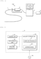
- FIG. 1 is an explanatory diagram showing a configuration example of a diagnostic imaging apparatus 100.
- the diagnostic imaging apparatus 100 is an apparatus for generating a medical image including an ultrasound tomographic image of a blood vessel (lumen organ) by an intra vascular ultra sound (IVUS) method, and performing an ultrasound examination and diagnosis inside the blood vessel.
- the diagnostic imaging apparatus 100 according to the first embodiment is an apparatus that analyzes a bifurcating structure of the blood vessel to discriminate between a main trunk A and a side branch B branched from the main trunk A, and superimposes and displays guide images G1 and G2 (see FIG. 9 ) showing the bifurcating structure on the medical image.
- the diagnostic imaging apparatus 100 includes a catheter 1, a motor drive unit (MDU) 2, an image processing device (information processing device) 3, a display device 4, and an input device 5.
- the diagnostic imaging apparatus 100 generates the medical image including the ultrasound tomographic image of the blood vessel by the IVUS method using the catheter 1, and performs the ultrasound examination inside the blood vessel.
- the catheter 1 is a diagnostic imaging catheter for obtaining the ultrasound tomographic image of the blood vessel by the IVUS method.
- the catheter 1 includes, at a distal end portion thereof, an ultrasound probe for obtaining the ultrasound tomographic image of the blood vessel.
- the ultrasound probe includes an ultrasound transducer that emits an ultrasound in the blood vessel, and an ultrasound sensor that receives a reflected wave (ultrasound echo) reflected by a biological tissue of the blood vessel or a medical equipment.
- the ultrasound probe is configured to move forward and backward in a longitudinal direction of the blood vessel while rotating in a circumferential direction of the blood vessel.
- the MDU 2 is a drive apparatus to which the catheter 1 is detachably attached, and controls, by driving a built-in motor according to an operation of a health care worker, an operation of the catheter 1 inserted into the blood vessel.
- the MDU 2 rotates the ultrasound probe of the catheter 1 in the circumferential direction while moving the ultrasound probe from a distal end (distal position) side to a proximal end (proximal position) side (see FIG. 3 ).
- the ultrasound probe continuously scans the inside of the blood vessel at a predetermined time interval, and outputs reflected wave data of a detected ultrasound to the image processing device 3.
- the image processing device 3 generates, in a chronological order, a plurality of medical images including the tomographic image of the blood vessel based on the reflected wave data output from the ultrasound probe of the catheter 1 (see FIG. 3 ). Since the ultrasound probe scans the inside of the blood vessel while moving from the distal end (distal position) side to the proximal end (proximal position) side in the blood vessel, the plurality of medical images in the chronological order are tomographic images of the blood vessel observed at a plurality of locations from the distal position to the proximal position.
- the display device 4 is a liquid crystal display panel, an organic EL display panel, or the like, and displays the medical image generated by the image processing device 3.
- the input device 5 is an input interface such as a keyboard or a mouse that receives an input of various setting values when an inspection is performed, an operation on the image processing device 3, and the like.
- the input device 5 may be a touch panel, a soft key, a hard key, or the like provided in the display device 4.
- FIG. 2 is a block diagram showing a configuration example of the image processing device 3.
- the image processing device 3 is a computer, and includes a control unit 31, a main storage unit 32, an input and output I/F 33, and an auxiliary storage unit 34.
- the control unit 31 is implemented by using an arithmetic processing device such as one or more central processing units (CPUs), micro-processing units (MPUs), graphics processing units (GPUs), general-purpose computing on graphics processing units (GPGPUs), tensor processing units (TPUs), or the like.
- CPUs central processing units
- MPUs micro-processing units
- GPUs graphics processing units
- GPGPUs general-purpose computing on graphics processing units
- TPUs tensor processing units
- the main storage unit 32 is a temporary storage area such as a static random access memory (SRAM), a dynamic random access memory (DRAM), or a flash memory, and temporarily stores data necessary for the control unit 31 to perform arithmetic processing.
- SRAM static random access memory
- DRAM dynamic random access memory
- flash memory temporary storage area
- the input and output I/F 33 is an interface through which the catheter 1, the display device 4, and the input device 5 are connected.
- the control unit 31 acquires the reflected wave data output from the ultrasound probe via the input and output I/F 33.
- the control unit 31 outputs a medical image signal to the display device 4 via the input and output I/F 33. Further, the control unit 31 receives, via the input and output I/F 33, information input to the input device 5.
- the auxiliary storage unit 34 is a storage device such as a hard disk, an electrically erasable programmable ROM (EEPROM), or a flash memory.
- the auxiliary storage unit 34 stores a computer program P performed by the control unit 31 and various types of data required for processing of the control unit 31.
- the auxiliary storage unit 34 stores a learning model 341.
- the learning model 341 is a model that recognizes a predetermined object included in the medical image.
- the learning model 341 can classify an object in units of pixels by using an image recognition technique using semantic segmentation, and can recognize a lumen boundary of a blood vessel included in the medical image.
- the auxiliary storage unit 34 may be an external storage device connected to the image processing device 3.
- the computer program P may be written in the auxiliary storage unit 34 at a stage of manufacturing the image processing device 3, or the image processing device 3 may acquire the computer program P, which is distributed by a remote server apparatus, through communication and store the computer program P in the auxiliary storage unit 34.
- the computer program P may be in a state of being recorded readably in a recording medium 3a such as a magnetic disk, an optical disk, or a semiconductor memory.
- the control unit 31 reads and performs the computer program P stored in the auxiliary storage unit 34 to acquire the medical image generated by the diagnostic imaging apparatus 100 and perform processing of detecting the lumen boundary of the blood vessel included in the medical image. Specifically, the control unit 31 detects an image region of the lumen boundary in the medical image using the learning model 341. In particular, the control unit 31 according to the first embodiment has a function of discriminating between the main trunk A and the side branch B at a bifurcated portion of the blood vessel. Then, the image processing device 3 outputs a recognition result of the lumen boundary to the diagnostic imaging apparatus 100, and displays the guide images G1 and G2 (see FIG. 9 ) indicating positions and regions of the main trunk A and the side branch B in order to enable the health care worker to easily recognize the lumen boundaries of the main trunk A and the side branch B which are results.
- FIG. 3 is an explanatory diagram showing an image recognition method using the learning model 341.
- the learning model 341 is trained such that the region of the lumen boundary of the blood vessel in the medical image can be recognized in units of pixels.
- the learning model 341 is, for example, a convolutional neural network (CNN) that is trained by deep learning.
- CNN convolutional neural network
- the learning model 341 recognizes an object in units of pixels by an image recognition technique using so-called semantic segmentation.
- the learning model 341 includes an input layer 341a which receives the medical image, an intermediate layer 341b that extracts and restores feature data of the image, and an output layer 341c that outputs a label image showing the object included in the medical image in units of pixels.
- the learning model 341 is, for example, U-Net.
- the input layer 341a of the learning model 341 includes a plurality of neurons that receive an input of a pixel value of a pixel included in the medical image, and transmits the received pixel value to the intermediate layer 341b.
- the intermediate layer 341b includes a convolutional layer (CONV layer) and a deconvolutional layer (DECONV layer).
- CONV layer convolutional layer
- DECONV layer deconvolutional layer
- the convolutional layer is a layer that performs dimensional compression on image data.
- the feature data of the object is extracted by the dimensional compression.
- the deconvolutional layer performs deconvolution processing to reconstruct to an original dimension.
- the output layer 341c includes one or more neurons that output the label image.
- the label image is, for example, an image in which pixels corresponding to the lumen boundary of the blood vessel are of class "1" and pixels corresponding to the other images are of class "0".
- the learning model 341 can be generated by preparing training data including a medical image including the main trunk A, a label image showing pixels and a center position of a lumen boundary of the main trunk A in the medical image, a medical image including the main trunk A and the side branch B which are completely separated from each other, a label image showing pixels and center positions of the lumen boundaries of the main trunk A and the side branch B in the medical image, a medical image including the bifurcated portion of the main trunk A and the side branch B, and a label image showing pixels of a lumen boundary of the bifurcated portion in the medical image, and performing machine learning on an untrained neural network using the training data.
- a main trunk cross-section and a side branch cross-section are combined to each other.
- a label image showing a region of the lumen boundary of the main trunk A in units of pixels is obtained by inputting the medical image including the main trunk A into the learning model 341.
- a label image showing regions of the main trunk A and the side branch B in units of pixels is obtained in the learning model 341 by inputting the medical image including both the main trunk A and the side branch B into the learning model 341.
- a label image showing a region of the bifurcated portion in units of pixels is obtained in the learning model 341 by inputting the medical image including the bifurcated portion of the main trunk A and the side branch B into the learning model 341.
- the main trunk A and the side branch B are output without being discriminated.
- FIG. 4 is an explanatory diagram showing a branched blood vessel
- FIG. 5 is an explanatory diagram showing tomographic images of the blood vessel obtained by scanning the branched blood vessel.
- the tomographic images on planes denoted by reference numerals a to f in FIG. 4 are as shown in FIG. 5 .
- the main trunk A and the side branch B branched from the main trunk A are completely separated from each other (a cross-section indicated by the reference numeral f)
- the main trunk A and the side branch B in the medical image can be easily understood.
- structures of the main trunk A and the side branch B cannot be easily understood.
- the image processing device 3 performs processing of recognizing the structures of the main trunk A and the side branch B in the bifurcated portion and displaying the guide images G1 and G2 for supporting the health care worker to recognize the bifurcating structure.
- FIG. 6 is a flowchart showing a procedure of the information processing method
- FIG. 7 is a side view of the blood vessel showing a method for specifying the bifurcating structure of the blood vessel
- FIG. 8 is a cross-sectional view of the blood vessel showing the method for specifying the bifurcating structure of the blood vessel.
- the control unit 31 acquires the plurality of medical images in the chronological order from the diagnostic imaging apparatus 100 (step S11).
- the plurality of medical images in the chronological order acquired here are, for example, images of the tomographic images observed from the distal position to the proximal position of the blood vessel.
- the control unit 31 selects a plurality of medical images in a distal portion (step S12).
- the control unit 31 may select at least two medical images each including the main trunk A and the side branch B that are completely separated from each other. For example, as shown in FIG. 7 , the control unit 31 may select a medical image on a cutting plane f and a medical image on a cutting plane g.
- control unit 31 detects the lumen boundaries and the center positions of the main trunk A and the side branch B included in the medical image by inputting the medical images selected in step S12 into the learning model 341 (step S13).
- the control unit 31 specifies the bifurcating structure of the blood vessel based on a detection result of step S13 as shown in FIG. 8 (step S14).
- a time difference in capturing the two images selected in step S12 corresponds to a length of the main trunk A in the longitudinal direction.
- a product of a moving speed of the ultrasound probe during blood vessel scanning and the time difference corresponds to a length between locations at which the two medical images are captured.
- a straight line (broken line) passing through centers of the main trunks A included in the two medical images indicates a center line of the main trunk A.
- a straight line (broken line) passing through centers of the side branches B included in the two medical images indicates a center line of the side branch B.
- the above equation (3) describes one diameter, and a long diameter and a short diameter of the main trunk A can be calculated in the same way.
- the center position and the diameter of the blood vessel in another medical image may be calculated by polynomial interpolation based on the center positions of the blood vessel in three or more medical images.
- the diameter of the lumen boundary of the main trunk A may be estimated.
- the center position and the diameter of the side branch B in the medical image can also be calculated by the same method.
- the control unit 31 specifies a region in which straight lines indicating the lumen boundary of the main trunk A and straight lines indicating the lumen boundary of the side branch B intersect with each other as the bifurcated portion.
- the control unit 31 that finishes the processing of step S14 selects the medical image in the bifurcated portion (step S15), and detects the lumen boundaries of the main trunk A and the side branch B included in the medical image (step S16).
- the region of the lumen boundary of the main trunk A and the region of the lumen boundary of the side branch B in the bifurcated portion are recognized as regions that are partially combined.
- control unit 31 specifies, based on information indicating the structure of the bifurcated portion specified in step S14, a main trunk A portion and a side branch B portion in the regions of the lumen boundaries detected in step S16 (step S17).
- the center position and the diameter of the main trunk A in the medical image of the bifurcated portion can be obtained based on the information on the structure of the bifurcated portion specified in step S14. That is, the control unit 31 can obtain an elliptical line indicating the main trunk A in the medical image.
- the control unit 31 can recognize, as the lumen boundary of the main trunk A, a region in the vicinity of the elliptical line of the main trunk A obtained based on the information on the structure of the bifurcated portion in the lumen boundary detected in step S16. Similarly, the control unit 31 can recognize, as the lumen boundary of the main trunk A, a region in the vicinity of an elliptical line of the side branch B obtained based on the information on the structure of the bifurcated portion in the lumen boundary detected in step S16.
- control unit 31 selects the medical image in the proximal portion which is proximal of the bifurcated portion (step S18). If the number of branches is one, only the main trunk A is included in the medical image selected in step S18. The control unit 31 detects the lumen boundary and the center position of the main trunk A included in the medical image in the proximal portion (step S19).
- control unit 31 superimposes the guide images G1 and G2 indicating the main trunk A portion and the side branch B portion in the medical image onto the medical image, and displays the superimposed image (step S20).
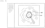
- FIG. 9 is an explanatory diagram showing a display example of the guide images G1 and G2.
- the control unit 31 superimposes the guide image G1 corresponding to the region of the lumen boundary of the main trunk A onto the medical image and displays the superimposed image.
- the guide image G1 is an image having substantially the same shape as the region of the lumen boundary of the main trunk A.
- control unit 31 superimposes the guide image G2 corresponding to the region of the lumen boundary of the side branch B onto the medical image and displays the superimposed image.
- the guide image G2 is an image having substantially the same shape as the region of the lumen boundary of the side branch B.
- the control unit 31 may display the guide images G1 and G2 in different modes for the guide image G1 and the guide image G2.
- the guide images G1 and G2 having different line types and colors may be displayed.
- An original image on which the guide images G1 and G2 are not superimposed may be displayed adjacently with an image obtained by superimposing the guide images G1 and G2 onto the medical image. Further, the image on which the guide images G1 and G2 are superimposed and the original image on which the guide images G1 and G2 are not superimposed may be selectively switched and displayed.
- control unit 31 may display the guide images G1 and G2 such that the lumen boundary of the main trunk A or the side branch B that does not appear in the medical image is complemented.
- the control unit 31 may display the guide images G1 and G2 such that the lumen boundary of the main trunk A or the side branch B that does not appear in the medical image is complemented.
- a part of the lumen boundary that is to be annular is missing, but the lumen boundary of the main trunk A and the lumen boundary of the side branch B may be displayed by estimating the missing part.
- the medical image obtained by scanning the blood vessel can be analyzed and the main trunk A and the side branch B of the blood vessel can be recognized.
- the guide images G1 and G2 showing the lumen boundaries of the main trunk A and the side branch B of the blood vessel are displayed, and the health care worker can be supported to recognize the lumen boundaries of the main trunk A and the side branch B.
- the image processing device 3, the computer program P, and the information processing method described in the first embodiment are examples, and are not limited to the configuration of the first embodiment.
- the blood vessel is exemplified as an observation target or a diagnosis target
- the invention can also be applied to a case in which a lumen organ such as a bowel other than the blood vessel is observed.
- the ultrasound image has been described as an example of the medical image, and the medical image is not limited to the ultrasound image.
- the medical image may be, for example, an optical coherence tomography (OCT) image.
- OCT optical coherence tomography
- An image processing device is different from that of the first embodiment in that a lumen boundary and a plaque of the blood vessel are recognized, diameters, cross-sectional areas, volumes, and the like of the main trunk A and the side branch B can be calculated and displayed, and a model image in which a bifurcating structure is reproduced can be generated and displayed, and thus the differences will be mainly described below. Since other configurations, and operations and effects are the same as those of the first embodiment, corresponding portions are denoted by the same reference numerals and detailed descriptions are omitted.
- the learning model 341 according to the second embodiment is, for example, a model that recognizes the lumen boundary and the plaque of the blood vessel included in the medical image.
- FIG. 10 is a flowchart showing a procedure of an information processing method according to the second embodiment.
- the control unit 31 according to the second embodiment performs the same processing as that of steps S11 to S20 of the first embodiment, and detects the lumen boundary and the plaque of the blood vessel in steps S33, S36, and S39.
- control unit 31 superimposes a guide image showing the plaque onto the medical image, and displays the superimposed image (step S40).
- a health care worker can select whether the guide image showing the plaque is necessary by using the input device 5.
- the control unit 31 does not display the guide image when receiving information indicating that the guide image is unnecessary, and displays the guide image when receiving information indicating that the guide image is necessary.
- control unit 31 calculates the cross-sectional diameter, the cross-sectional area, or the volume per unit length of a lumen of the main trunk A, and displays, on the display device 4, the calculated cross-sectional diameter, the calculated cross-sectional area, and the calculated volume of the lumen of the main trunk A in a superimposed manner (step S41).
- control unit 31 calculates the cross-sectional diameter, the cross-sectional area, or the volume per unit length of a lumen of the side branch B based on the bifurcating structure specified in step S34, and displays, on the display device 4, the calculated cross-sectional diameter, the calculated cross-sectional area, and the calculated volume of the lumen of the side branch B (step S42).
- a tomographic image of the side branch B scanned by the catheter 1 inserted through the main trunk A is a tomographic image (hereinafter, referred to as an oblique tomographic image) obtained by obliquely cutting the side branch B.
- control unit 31 converts a cross-sectional diameter, a cross-sectional area, or a volume of a lumen of the side branch B in the oblique tomographic image into a cross-sectional diameter, a cross-sectional area, or a volume of a lumen in a tomographic image (hereinafter, referred to as an axial tomographic image) obtained by cutting the side branch B substantially perpendicularly, that is, a tomographic image obtained by cutting the side branch B along a plane substantially perpendicular to a center line of the side branch B.
- an axial tomographic image a tomographic image obtained by cutting the side branch B substantially perpendicularly
- an angle ⁇ formed by a center line of the main trunk A and a center line of the side branch B may be calculated, the oblique tomographic image may be converted into the axial image using the angle ⁇ , and the cross-sectional diameter, the cross-sectional area, or the volume per unit length of the lumen of the side branch B may be calculated.
- control unit 31 reproduces the model image representing the bifurcating structure of the blood vessel based on the bifurcating structure calculated in step S34 and a recognition result of the lumen boundary and the plaque detected based on the medical image, and displays the reproduced model image on the display device 4 (step S43) .
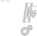
- FIGS. 11A to 11C are explanatory diagrams showing model images of the main trunk A and the side branch B.
- the control unit 31 may generate a cross section of the blood vessel as the model image.
- the model image shows a blood vessel wall portion, the lumen boundary, and the plaque portion of the blood vessel.
- control unit 31 may generate cross-sectional images of the main trunk A and the side branch B as the model images.
- the model images also show the blood vessel wall portion, the lumen boundary, and the plaque portion of the blood vessel.
- control unit 31 may generate a model image converted into the axial image.
- the image processing device 3 According to the computer program P, the image processing device 3, and the information processing method configured in this way, the guide image showing the plaque formed on the blood vessel wall can be displayed and the health care worker can be guided to recognize the plaque portion.
- the cross-sectional diameters, the areas, and the volumes of the lumens of the main trunk A and the side branch B can be calculated and displayed.
- the model image representing the bifurcating structure can be generated and displayed, and the health care worker can be guided to recognize the bifurcated portion of the blood vessel.
- the model image of the cross section displaying the lumen boundaries and plaques of the main trunk A and the side branch B, the plaque formed in the blood vessel can be recognized more easily.
- the plaque formed as a result can be recognized more easily.
- FIG. 12 is an explanatory diagram showing a configuration example of a diagnostic imaging system.
- the diagnostic imaging system according to a third embodiment is different from that of the first embodiment in that an information processing device 6, which is a server, performs processing of analyzing a medical image, and the above difference will be mainly described later. Since other configurations and effects are the same as those of the first embodiment or the second embodiment, the corresponding portions are denoted by the same reference numerals and detailed descriptions are omitted.
- the diagnostic imaging system includes the information processing device 6 and a diagnostic imaging apparatus 200.
- the information processing device 6 and the diagnostic imaging apparatus 200 are communicably connected to each other via a network N such as a local area network (LAN) or the Internet.
- the information processing device 6 and the diagnostic imaging apparatus 200 are communicably connected to each other via a network N such as a local area network (LAN) or the Internet.
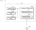
- FIG. 13 is a block diagram showing a configuration example of the information processing device 6.
- the information processing device 6 is a computer, and includes a control unit 61, a main storage unit 62, a communication unit 63, and an auxiliary storage unit 64.
- the communication unit 63 is a communication circuit for performing transmission and reception of data to and from the image processing device 3 via the network N.
- Hardware configurations of the control unit 61, the main storage unit 62, the communication unit 63, and the auxiliary storage unit 64 are the same as those of the image processing device 3 described in the first embodiment.
- the computer program P, a learning model 641, and a recording medium 6a stored in the auxiliary storage unit 64 are also the same as various programs, models, and the like of the first or second embodiment.
- the information processing device 6 may be a multi-computer including a plurality of computers, or may be a virtual machine virtually constructed by software.
- the information processing device 6 may be a local server installed in the same facility (hospital or the like) as the diagnostic imaging apparatus 200, or may be a cloud server communicably connected to the diagnostic imaging apparatus 200 via the Internet or the like.
- FIG. 14 is a flowchart showing a method for generating the learning model 641.
- the control unit 61 collects a plurality of medical images each including a main trunk cross-section (step S51). For example, the control unit 61 collects the medical images from the diagnostic imaging apparatus 200.
- control unit 61 collects a plurality of medical images each including the main trunk cross-section and a side branch cross-section (step S52). Similarly, the control unit 61 collects a plurality of medical images each including a bifurcated portion cross-section (step S53).
- control unit 61 collects a plurality of medical images each including the main trunk cross-section in which a plaque is formed (step S54). Then, the control unit 61 collects a plurality of medical images each including the main trunk cross-section and the side branch cross-section in which the plaques are formed (step S55). Similarly, the control unit 61 collects a plurality of medical images each including a bifurcated portion cross-section in which the plaques are formed (step S56).
- a label image of the medical image including the main trunk cross-section is an image showing pixels of the lumen boundary and pixels of the plaque in the main trunk A.
- a label image of the medical image including the main trunk cross-section and the side branch cross-section is an image showing pixels of the lumen boundaries and pixels of the plaques in the main trunk A and the side branch B.
- a label image of the medical image including the bifurcated portion cross-section is an image showing pixels of the lumen boundaries and pixels of the plaques in the main trunk A and the side branch B at the bifurcated portion.
- a label image of the medical image including the main trunk cross-section in which the plaque is formed is an image showing pixels of the lumen boundary and pixels of the plaque in the main trunk A, and pixels of the plaque.
- a label image of the medical image including the main trunk cross-section and the side branch cross-section in which the plaques are formed is an image showing pixels of the lumen boundaries and pixels of the plaques in the main trunk A and the side branch B, and pixels of the plaque.
- a label image of the medical image including the bifurcated portion cross-section in which the plaque is formed is an image showing pixels of the lumen boundaries and pixels of the plaques in the main trunk A and the side branch B at the bifurcated portion, and pixels of the plaque.
- control unit 61 generates the learning model 641 by performing machine learning on an untrained neural network using the generated training data (step S58).
- the label image showing a region of the lumen boundary of the main trunk A and a region of the plaque portion in units of pixels is obtained by inputting the medical image including the main trunk A into the learning model 641.
- the label image showing regions of the main trunk A and the side branch B and regions of the plaque portions in units of pixels is obtained in the learning model 641 by inputting the medical image including both the main trunk A and the side branch B into the learning model 641.
- the label image showing a region of the lumen boundaries and a region of the plaque portions at the bifurcated portion in units of pixels is obtained by inputting the medical image including bifurcated portion of the main trunk A and the side branch B into the learning model 641.
- the information processing device 6 configured in this way acquires the medical images from the image processing device 3 via the network N, performs processing similar to that of the image processing device 3 according to the first embodiment based on the acquired medical images, and transmits a recognition result of an object to the image apparatus.
- the image processing device 3 acquires the recognition result of the object transmitted from the information processing device 6, superimposes the guide images G1 and G2 indicating the regions of the main trunk A and the side branch B of the blood vessel onto the medical image, and displays the superimposed image on the display device 4, as shown in FIG. 9 .
- a medical image obtained by scanning the blood vessel can be analyzed and the main trunk A and the side branch B of the blood vessel can be recognized.
Landscapes
- Engineering & Computer Science (AREA)
- Health & Medical Sciences (AREA)
- Life Sciences & Earth Sciences (AREA)
- Physics & Mathematics (AREA)
- Computer Vision & Pattern Recognition (AREA)
- General Health & Medical Sciences (AREA)
- Medical Informatics (AREA)
- Nuclear Medicine, Radiotherapy & Molecular Imaging (AREA)
- Radiology & Medical Imaging (AREA)
- General Physics & Mathematics (AREA)
- Theoretical Computer Science (AREA)
- Biophysics (AREA)
- Animal Behavior & Ethology (AREA)
- Veterinary Medicine (AREA)
- Public Health (AREA)
- Pathology (AREA)
- Biomedical Technology (AREA)
- Heart & Thoracic Surgery (AREA)
- Molecular Biology (AREA)
- Surgery (AREA)
- Quality & Reliability (AREA)
- Geometry (AREA)
- Vascular Medicine (AREA)
- Computer Networks & Wireless Communication (AREA)
- Physiology (AREA)
- Image Analysis (AREA)
- Ultra Sonic Daignosis Equipment (AREA)
- Image Processing (AREA)
Abstract
Description
- The present disclosure relates to a computer program, an information processing method, an information processing device, and a method for generating a model.
- A medical image including an ultrasound tomographic image of a blood vessel is generated by an intra vascular ultrasound (IVUS) method using a catheter, and an ultrasound examination inside the blood vessel is performed. In the intra vascular ultrasound method, an intravascular diagnosis catheter moves an ultrasound sensor from a distal position to a proximal position of the blood vessel, and scans the blood vessel and surrounding tissues thereof.
- Meanwhile, for a purpose of assisting a doctor to perform diagnosis, a technique of adding information to the medical image by image processing or machine learning is developed.
- PTL 1:
JP-A-2019-165970 - However, there is a problem in that it is difficult to recognize an image of a lumen boundary of a bifurcated portion of the blood vessel in one tomographic image and discriminate between a main trunk and a side branch of the blood vessel, and useful information cannot be added to the medical image.
- An object of the present disclosure is to provide a computer program, an information processing method, an information processing device, and a method for generating a model capable of analyzing a medical image obtained by scanning a lumen organ, and recognizing a main trunk and a side branch of a blood vessel.
- A computer program according to the present disclosure causes a computer to perform processing of: acquiring a plurality of medical images generated based on signals detected by a catheter inserted into a lumen organ while the catheter is moving a sensor along a longitudinal direction of the lumen organ, the lumen organ including a main trunk, a side branch branched from the main trunk, and a bifurcated portion of the main trunk and the side branch; and recognizing a main trunk cross-section, a side branch cross-section, and a bifurcated portion cross-section by inputting the acquired medical images into a learning model configured to recognize the main trunk cross-section, the side branch cross-section, and the bifurcated portion cross-section.
- An information processing method according to the present disclosure includes a computer performing processing of: acquiring a plurality of medical images generated based on signals detected by a catheter inserted into a lumen organ while the catheter is moving a sensor along a longitudinal direction of the lumen organ, the lumen organ including a main trunk, a side branch branched from the main trunk, and a bifurcated portion of the main trunk and the side branch; and recognizing a main trunk cross-section, a side branch cross-section, and a bifurcated portion cross-section by inputting the acquired medical images into a learning model configured to recognize the main trunk cross-section, the side branch cross-section, and the bifurcated portion cross-section.
- An information processing device according to the present disclosure includes: an acquisition unit configured to acquire a plurality of medical images generated based on signals detected by a catheter inserted into a lumen organ while the catheter is moving a sensor along a longitudinal direction of the lumen organ, the lumen organ including a main trunk, a side branch branched from the main trunk, and a bifurcated portion of the main trunk and the side branch; and a learning model configured to recognize, when the acquired medical images are input, a main trunk cross-section, a side branch cross-section, and a bifurcated portion cross-section, and output information indicating the main trunk cross-section, the side branch cross-section, and the bifurcated portion cross-section.
- A method for generating a model according to the present disclosure includes performing the following processing in a computer: generating training data in which data indicating a lumen cross-section is attached to a plurality of medical images each including a main trunk cross-section, a plurality of medical images each including the main trunk cross-section and a side branch cross-section, and a plurality of medical images each including a bifurcated portion cross-section that are generated based on signals detected by a catheter inserted into a lumen organ while the catheter is moving a sensor along a longitudinal direction of a lumen organ, the lumen organ including a main trunk, a side branch branched from the main trunk, and a bifurcated portion of the main trunk and the side branch; and generating, based on the generated training data, a learning model configured to recognize the main trunk cross-section, the side branch cross-section, and the bifurcated portion cross-section when the medical images are input.
- According to the present disclosure, a medical image obtained by scanning a lumen organ can be analyzed and a main trunk and a side branch of a blood vessel can be recognized.
-
-
FIG. 1 is an explanatory diagram showing a configuration example of a diagnostic imaging apparatus. -
FIG. 2 is a block diagram showing a configuration example of an image processing device. -
FIG. 3 is an explanatory diagram showing an image recognition method using a learning model. -
FIG. 4 is an explanatory diagram showing a branched blood vessel. -
FIG. 5 is an explanatory diagram showing tomographic images of the blood vessel obtained by scanning the branched blood vessel. -
FIG. 6 is a flowchart showing a procedure of an information processing method according to a first embodiment. -
FIG. 7 is a side view of a blood vessel showing a method for specifying a bifurcating structure of the blood vessel. -
FIG. 8 is a cross-sectional view of the blood vessel showing the method for specifying the bifurcating structure of the blood vessel. -
FIG. 9 is an explanatory diagram showing a display example of guide images. -
FIG. 10 is a flowchart showing a procedure of an information processing method according to a second embodiment. -
FIG. 11A is an explanatory diagram showing model images of a main trunk and a side branch. -
FIG. 11B is an explanatory diagram showing model images of the main trunk and the side branch. -
FIG. 11C is an explanatory diagram showing model images of the main trunk and the side branch. -
FIG. 12 is an explanatory diagram showing a configuration example of a diagnostic imaging system. -
FIG. 13 is a block diagram showing a configuration example of an information processing device. -
FIG. 14 is a flowchart showing a method for generating a learning model. - Specific examples of a computer program, an information processing method, an information processing device, and a method for generating a model according to embodiments of the invention will be described below with reference to the drawings.
-
FIG. 1 is an explanatory diagram showing a configuration example of adiagnostic imaging apparatus 100. Thediagnostic imaging apparatus 100 is an apparatus for generating a medical image including an ultrasound tomographic image of a blood vessel (lumen organ) by an intra vascular ultra sound (IVUS) method, and performing an ultrasound examination and diagnosis inside the blood vessel. In particular, thediagnostic imaging apparatus 100 according to the first embodiment is an apparatus that analyzes a bifurcating structure of the blood vessel to discriminate between a main trunk A and a side branch B branched from the main trunk A, and superimposes and displays guide images G1 and G2 (seeFIG. 9 ) showing the bifurcating structure on the medical image. - The
diagnostic imaging apparatus 100 includes acatheter 1, a motor drive unit (MDU) 2, an image processing device (information processing device) 3, adisplay device 4, and aninput device 5. Thediagnostic imaging apparatus 100 generates the medical image including the ultrasound tomographic image of the blood vessel by the IVUS method using thecatheter 1, and performs the ultrasound examination inside the blood vessel. - The
catheter 1 is a diagnostic imaging catheter for obtaining the ultrasound tomographic image of the blood vessel by the IVUS method. Thecatheter 1 includes, at a distal end portion thereof, an ultrasound probe for obtaining the ultrasound tomographic image of the blood vessel. The ultrasound probe includes an ultrasound transducer that emits an ultrasound in the blood vessel, and an ultrasound sensor that receives a reflected wave (ultrasound echo) reflected by a biological tissue of the blood vessel or a medical equipment. The ultrasound probe is configured to move forward and backward in a longitudinal direction of the blood vessel while rotating in a circumferential direction of the blood vessel. - The MDU 2 is a drive apparatus to which the
catheter 1 is detachably attached, and controls, by driving a built-in motor according to an operation of a health care worker, an operation of thecatheter 1 inserted into the blood vessel. TheMDU 2 rotates the ultrasound probe of thecatheter 1 in the circumferential direction while moving the ultrasound probe from a distal end (distal position) side to a proximal end (proximal position) side (seeFIG. 3 ). The ultrasound probe continuously scans the inside of the blood vessel at a predetermined time interval, and outputs reflected wave data of a detected ultrasound to theimage processing device 3. - The
image processing device 3 generates, in a chronological order, a plurality of medical images including the tomographic image of the blood vessel based on the reflected wave data output from the ultrasound probe of the catheter 1 (seeFIG. 3 ). Since the ultrasound probe scans the inside of the blood vessel while moving from the distal end (distal position) side to the proximal end (proximal position) side in the blood vessel, the plurality of medical images in the chronological order are tomographic images of the blood vessel observed at a plurality of locations from the distal position to the proximal position. - The
display device 4 is a liquid crystal display panel, an organic EL display panel, or the like, and displays the medical image generated by theimage processing device 3. - The
input device 5 is an input interface such as a keyboard or a mouse that receives an input of various setting values when an inspection is performed, an operation on theimage processing device 3, and the like. Theinput device 5 may be a touch panel, a soft key, a hard key, or the like provided in thedisplay device 4. -
FIG. 2 is a block diagram showing a configuration example of theimage processing device 3. Theimage processing device 3 is a computer, and includes acontrol unit 31, amain storage unit 32, an input and output I/F 33, and anauxiliary storage unit 34. - The
control unit 31 is implemented by using an arithmetic processing device such as one or more central processing units (CPUs), micro-processing units (MPUs), graphics processing units (GPUs), general-purpose computing on graphics processing units (GPGPUs), tensor processing units (TPUs), or the like. - The
main storage unit 32 is a temporary storage area such as a static random access memory (SRAM), a dynamic random access memory (DRAM), or a flash memory, and temporarily stores data necessary for thecontrol unit 31 to perform arithmetic processing. - The input and output I/
F 33 is an interface through which thecatheter 1, thedisplay device 4, and theinput device 5 are connected. Thecontrol unit 31 acquires the reflected wave data output from the ultrasound probe via the input and output I/F 33. Thecontrol unit 31 outputs a medical image signal to thedisplay device 4 via the input and output I/F 33. Further, thecontrol unit 31 receives, via the input and output I/F 33, information input to theinput device 5. - The
auxiliary storage unit 34 is a storage device such as a hard disk, an electrically erasable programmable ROM (EEPROM), or a flash memory. Theauxiliary storage unit 34 stores a computer program P performed by thecontrol unit 31 and various types of data required for processing of thecontrol unit 31. In addition, theauxiliary storage unit 34 stores alearning model 341. - The
learning model 341 is a model that recognizes a predetermined object included in the medical image. For example, thelearning model 341 can classify an object in units of pixels by using an image recognition technique using semantic segmentation, and can recognize a lumen boundary of a blood vessel included in the medical image. - The
auxiliary storage unit 34 may be an external storage device connected to theimage processing device 3. The computer program P may be written in theauxiliary storage unit 34 at a stage of manufacturing theimage processing device 3, or theimage processing device 3 may acquire the computer program P, which is distributed by a remote server apparatus, through communication and store the computer program P in theauxiliary storage unit 34. The computer program P may be in a state of being recorded readably in arecording medium 3a such as a magnetic disk, an optical disk, or a semiconductor memory. - The
control unit 31 reads and performs the computer program P stored in theauxiliary storage unit 34 to acquire the medical image generated by thediagnostic imaging apparatus 100 and perform processing of detecting the lumen boundary of the blood vessel included in the medical image. Specifically, thecontrol unit 31 detects an image region of the lumen boundary in the medical image using thelearning model 341. In particular, thecontrol unit 31 according to the first embodiment has a function of discriminating between the main trunk A and the side branch B at a bifurcated portion of the blood vessel. Then, theimage processing device 3 outputs a recognition result of the lumen boundary to thediagnostic imaging apparatus 100, and displays the guide images G1 and G2 (seeFIG. 9 ) indicating positions and regions of the main trunk A and the side branch B in order to enable the health care worker to easily recognize the lumen boundaries of the main trunk A and the side branch B which are results. -
FIG. 3 is an explanatory diagram showing an image recognition method using thelearning model 341. Thelearning model 341 is trained such that the region of the lumen boundary of the blood vessel in the medical image can be recognized in units of pixels. - The
learning model 341 is, for example, a convolutional neural network (CNN) that is trained by deep learning. Thelearning model 341 recognizes an object in units of pixels by an image recognition technique using so-called semantic segmentation. - The
learning model 341 includes aninput layer 341a which receives the medical image, anintermediate layer 341b that extracts and restores feature data of the image, and anoutput layer 341c that outputs a label image showing the object included in the medical image in units of pixels. Thelearning model 341 is, for example, U-Net. - The
input layer 341a of thelearning model 341 includes a plurality of neurons that receive an input of a pixel value of a pixel included in the medical image, and transmits the received pixel value to theintermediate layer 341b. Theintermediate layer 341b includes a convolutional layer (CONV layer) and a deconvolutional layer (DECONV layer). The convolutional layer is a layer that performs dimensional compression on image data. The feature data of the object is extracted by the dimensional compression. The deconvolutional layer performs deconvolution processing to reconstruct to an original dimension. By the reconstruction processing in the deconvolutional layer, a binarized label image indicating whether the pixels in the image are an object is generated. Theoutput layer 341c includes one or more neurons that output the label image. The label image is, for example, an image in which pixels corresponding to the lumen boundary of the blood vessel are of class "1" and pixels corresponding to the other images are of class "0". - The
learning model 341 can be generated by preparing training data including a medical image including the main trunk A, a label image showing pixels and a center position of a lumen boundary of the main trunk A in the medical image, a medical image including the main trunk A and the side branch B which are completely separated from each other, a label image showing pixels and center positions of the lumen boundaries of the main trunk A and the side branch B in the medical image, a medical image including the bifurcated portion of the main trunk A and the side branch B, and a label image showing pixels of a lumen boundary of the bifurcated portion in the medical image, and performing machine learning on an untrained neural network using the training data. In the medical image including the bifurcated portion, a main trunk cross-section and a side branch cross-section are combined to each other. - As shown in
FIG. 3 , according to thelearning model 341 trained in this way, a label image showing a region of the lumen boundary of the main trunk A in units of pixels is obtained by inputting the medical image including the main trunk A into thelearning model 341. A label image showing regions of the main trunk A and the side branch B in units of pixels is obtained in thelearning model 341 by inputting the medical image including both the main trunk A and the side branch B into thelearning model 341. Further, a label image showing a region of the bifurcated portion in units of pixels is obtained in thelearning model 341 by inputting the medical image including the bifurcated portion of the main trunk A and the side branch B into thelearning model 341. In the label images obtained here, the main trunk A and the side branch B are output without being discriminated. -
FIG. 4 is an explanatory diagram showing a branched blood vessel, andFIG. 5 is an explanatory diagram showing tomographic images of the blood vessel obtained by scanning the branched blood vessel. The tomographic images on planes denoted by reference numerals a to f inFIG. 4 are as shown inFIG. 5 . When the main trunk A and the side branch B branched from the main trunk A are completely separated from each other (a cross-section indicated by the reference numeral f), the main trunk A and the side branch B in the medical image can be easily understood. However, in the bifurcated portion of the blood vessel (cross-sections indicated by the reference numerals c, d, and e), structures of the main trunk A and the side branch B cannot be easily understood. - The
image processing device 3 according to the first embodiment performs processing of recognizing the structures of the main trunk A and the side branch B in the bifurcated portion and displaying the guide images G1 and G2 for supporting the health care worker to recognize the bifurcating structure. -
FIG. 6 is a flowchart showing a procedure of the information processing method,FIG. 7 is a side view of the blood vessel showing a method for specifying the bifurcating structure of the blood vessel, andFIG. 8 is a cross-sectional view of the blood vessel showing the method for specifying the bifurcating structure of the blood vessel. - The
control unit 31 acquires the plurality of medical images in the chronological order from the diagnostic imaging apparatus 100 (step S11). The plurality of medical images in the chronological order acquired here are, for example, images of the tomographic images observed from the distal position to the proximal position of the blood vessel. - The
control unit 31 selects a plurality of medical images in a distal portion (step S12). Thecontrol unit 31 may select at least two medical images each including the main trunk A and the side branch B that are completely separated from each other. For example, as shown inFIG. 7 , thecontrol unit 31 may select a medical image on a cutting plane f and a medical image on a cutting plane g. - Then, the
control unit 31 detects the lumen boundaries and the center positions of the main trunk A and the side branch B included in the medical image by inputting the medical images selected in step S12 into the learning model 341 (step S13). - Next, the
control unit 31 specifies the bifurcating structure of the blood vessel based on a detection result of step S13 as shown inFIG. 8 (step S14). A time difference in capturing the two images selected in step S12 corresponds to a length of the main trunk A in the longitudinal direction. Specifically, a product of a moving speed of the ultrasound probe during blood vessel scanning and the time difference corresponds to a length between locations at which the two medical images are captured. InFIG. 8 , a straight line (broken line) passing through centers of the main trunks A included in the two medical images indicates a center line of the main trunk A. A straight line (broken line) passing through centers of the side branches B included in the two medical images indicates a center line of the side branch B. - When center coordinates of the main trunk A imaged at a scanning time point t1 are (x1, y1) and center coordinates of the main trunk A imaged at a scanning time point t2 = t + Δt are (x2, y2), center coordinates (xN, yN) of the main trunk A at the bifurcated portion imaged at a scanning time point tN = t + NΔt are expressed by the following equations (1) and (2) .


- When a diameter of the main trunk A imaged at the scanning time point t1 is r1 and a diameter of the main trunk A imaged at the scanning time point t2 = t + Δt is r2, a center coordinate rN of the main trunk A at the bifurcated portion imaged at the scanning time point tN = t + NΔt is expressed by the following equation (3).

- The above equation (3) describes one diameter, and a long diameter and a short diameter of the main trunk A can be calculated in the same way.
- Although an example in which the above equations (1) to (3) are used to estimate the center position and the diameter of the blood vessel in the bifurcated portion by linear interpolation based on the center positions and the diameters of the present case obtained from the two medical images has been described, the center position and the diameter of the blood vessel in another medical image may be calculated by polynomial interpolation based on the center positions of the blood vessel in three or more medical images.
- Similarly, the diameter of the lumen boundary of the main trunk A may be estimated. In addition, the center position and the diameter of the side branch B in the medical image can also be calculated by the same method.
- The
control unit 31 specifies a region in which straight lines indicating the lumen boundary of the main trunk A and straight lines indicating the lumen boundary of the side branch B intersect with each other as the bifurcated portion. - The
control unit 31 that finishes the processing of step S14 selects the medical image in the bifurcated portion (step S15), and detects the lumen boundaries of the main trunk A and the side branch B included in the medical image (step S16). The region of the lumen boundary of the main trunk A and the region of the lumen boundary of the side branch B in the bifurcated portion are recognized as regions that are partially combined. - Then, the
control unit 31 specifies, based on information indicating the structure of the bifurcated portion specified in step S14, a main trunk A portion and a side branch B portion in the regions of the lumen boundaries detected in step S16 (step S17). The center position and the diameter of the main trunk A in the medical image of the bifurcated portion can be obtained based on the information on the structure of the bifurcated portion specified in step S14. That is, thecontrol unit 31 can obtain an elliptical line indicating the main trunk A in the medical image. Thecontrol unit 31 can recognize, as the lumen boundary of the main trunk A, a region in the vicinity of the elliptical line of the main trunk A obtained based on the information on the structure of the bifurcated portion in the lumen boundary detected in step S16. Similarly, thecontrol unit 31 can recognize, as the lumen boundary of the main trunk A, a region in the vicinity of an elliptical line of the side branch B obtained based on the information on the structure of the bifurcated portion in the lumen boundary detected in step S16. - Next, the
control unit 31 selects the medical image in the proximal portion which is proximal of the bifurcated portion (step S18). If the number of branches is one, only the main trunk A is included in the medical image selected in step S18. Thecontrol unit 31 detects the lumen boundary and the center position of the main trunk A included in the medical image in the proximal portion (step S19). - Then, the
control unit 31 superimposes the guide images G1 and G2 indicating the main trunk A portion and the side branch B portion in the medical image onto the medical image, and displays the superimposed image (step S20). -
FIG. 9 is an explanatory diagram showing a display example of the guide images G1 and G2. In the medical image of the bifurcated portion, as shown inFIG. 9 , cross-sections of the main trunk A and the side branch B are partially combined, and it is difficult to clearly discriminate between the lumen boundary of the main trunk A portion and the lumen boundary of the side branch B portion. Therefore, thecontrol unit 31 superimposes the guide image G1 corresponding to the region of the lumen boundary of the main trunk A onto the medical image and displays the superimposed image. The guide image G1 is an image having substantially the same shape as the region of the lumen boundary of the main trunk A. - Further, the
control unit 31 superimposes the guide image G2 corresponding to the region of the lumen boundary of the side branch B onto the medical image and displays the superimposed image. The guide image G2 is an image having substantially the same shape as the region of the lumen boundary of the side branch B. - The
control unit 31 may display the guide images G1 and G2 in different modes for the guide image G1 and the guide image G2. For example, the guide images G1 and G2 having different line types and colors may be displayed. An original image on which the guide images G1 and G2 are not superimposed may be displayed adjacently with an image obtained by superimposing the guide images G1 and G2 onto the medical image. Further, the image on which the guide images G1 and G2 are superimposed and the original image on which the guide images G1 and G2 are not superimposed may be selectively switched and displayed. - In addition, the
control unit 31 may display the guide images G1 and G2 such that the lumen boundary of the main trunk A or the side branch B that does not appear in the medical image is complemented. For example, in the example shown inFIG. 9 , a part of the lumen boundary that is to be annular is missing, but the lumen boundary of the main trunk A and the lumen boundary of the side branch B may be displayed by estimating the missing part. - According to the computer program P, the
image processing device 3, and the information processing method configured in this way, the medical image obtained by scanning the blood vessel can be analyzed and the main trunk A and the side branch B of the blood vessel can be recognized. - In addition, the guide images G1 and G2 showing the lumen boundaries of the main trunk A and the side branch B of the blood vessel are displayed, and the health care worker can be supported to recognize the lumen boundaries of the main trunk A and the side branch B.
- The
image processing device 3, the computer program P, and the information processing method described in the first embodiment are examples, and are not limited to the configuration of the first embodiment. - For example, in the first embodiment, although the blood vessel is exemplified as an observation target or a diagnosis target, the invention can also be applied to a case in which a lumen organ such as a bowel other than the blood vessel is observed.
- The ultrasound image has been described as an example of the medical image, and the medical image is not limited to the ultrasound image. The medical image may be, for example, an optical coherence tomography (OCT) image.
- An image processing device according to a second embodiment is different from that of the first embodiment in that a lumen boundary and a plaque of the blood vessel are recognized, diameters, cross-sectional areas, volumes, and the like of the main trunk A and the side branch B can be calculated and displayed, and a model image in which a bifurcating structure is reproduced can be generated and displayed, and thus the differences will be mainly described below. Since other configurations, and operations and effects are the same as those of the first embodiment, corresponding portions are denoted by the same reference numerals and detailed descriptions are omitted.
- The
learning model 341 according to the second embodiment is, for example, a model that recognizes the lumen boundary and the plaque of the blood vessel included in the medical image. -
FIG. 10 is a flowchart showing a procedure of an information processing method according to the second embodiment. Thecontrol unit 31 according to the second embodiment performs the same processing as that of steps S11 to S20 of the first embodiment, and detects the lumen boundary and the plaque of the blood vessel in steps S33, S36, and S39. - Next, the
control unit 31 superimposes a guide image showing the plaque onto the medical image, and displays the superimposed image (step S40). A health care worker can select whether the guide image showing the plaque is necessary by using theinput device 5. Thecontrol unit 31 does not display the guide image when receiving information indicating that the guide image is unnecessary, and displays the guide image when receiving information indicating that the guide image is necessary. - Next, the
control unit 31 calculates the cross-sectional diameter, the cross-sectional area, or the volume per unit length of a lumen of the main trunk A, and displays, on thedisplay device 4, the calculated cross-sectional diameter, the calculated cross-sectional area, and the calculated volume of the lumen of the main trunk A in a superimposed manner (step S41). - Similarly, the
control unit 31 calculates the cross-sectional diameter, the cross-sectional area, or the volume per unit length of a lumen of the side branch B based on the bifurcating structure specified in step S34, and displays, on thedisplay device 4, the calculated cross-sectional diameter, the calculated cross-sectional area, and the calculated volume of the lumen of the side branch B (step S42). However, as shown inFIG. 8 , a tomographic image of the side branch B scanned by thecatheter 1 inserted through the main trunk A is a tomographic image (hereinafter, referred to as an oblique tomographic image) obtained by obliquely cutting the side branch B. Therefore, thecontrol unit 31 converts a cross-sectional diameter, a cross-sectional area, or a volume of a lumen of the side branch B in the oblique tomographic image into a cross-sectional diameter, a cross-sectional area, or a volume of a lumen in a tomographic image (hereinafter, referred to as an axial tomographic image) obtained by cutting the side branch B substantially perpendicularly, that is, a tomographic image obtained by cutting the side branch B along a plane substantially perpendicular to a center line of the side branch B. For example, an angle θ formed by a center line of the main trunk A and a center line of the side branch B may be calculated, the oblique tomographic image may be converted into the axial image using the angle θ, and the cross-sectional diameter, the cross-sectional area, or the volume per unit length of the lumen of the side branch B may be calculated. - Next, the
control unit 31 reproduces the model image representing the bifurcating structure of the blood vessel based on the bifurcating structure calculated in step S34 and a recognition result of the lumen boundary and the plaque detected based on the medical image, and displays the reproduced model image on the display device 4 (step S43) . -
FIGS. 11A to 11C are explanatory diagrams showing model images of the main trunk A and the side branch B. For example, as shown in upper parts ofFIGS. 11A to 11C , thecontrol unit 31 may generate a cross section of the blood vessel as the model image. The model image shows a blood vessel wall portion, the lumen boundary, and the plaque portion of the blood vessel. - Further, as shown in lower parts of
FIGS. 11A to 11C , thecontrol unit 31 may generate cross-sectional images of the main trunk A and the side branch B as the model images. The model images also show the blood vessel wall portion, the lumen boundary, and the plaque portion of the blood vessel. Further, when generating a cross-sectional image of the side branch B, thecontrol unit 31 may generate a model image converted into the axial image. - According to the computer program P, the
image processing device 3, and the information processing method configured in this way, the guide image showing the plaque formed on the blood vessel wall can be displayed and the health care worker can be guided to recognize the plaque portion. - The cross-sectional diameters, the areas, and the volumes of the lumens of the main trunk A and the side branch B can be calculated and displayed.
- The model image representing the bifurcating structure can be generated and displayed, and the health care worker can be guided to recognize the bifurcated portion of the blood vessel. In particular, by displaying the model image of the cross section displaying the lumen boundaries and plaques of the main trunk A and the side branch B, the plaque formed in the blood vessel can be recognized more easily.
- Further, by displaying the axial cross-sections of the main trunk A and the side branch B, the plaque formed as a result can be recognized more easily.
-
FIG. 12 is an explanatory diagram showing a configuration example of a diagnostic imaging system. The diagnostic imaging system according to a third embodiment is different from that of the first embodiment in that aninformation processing device 6, which is a server, performs processing of analyzing a medical image, and the above difference will be mainly described later. Since other configurations and effects are the same as those of the first embodiment or the second embodiment, the corresponding portions are denoted by the same reference numerals and detailed descriptions are omitted. - The diagnostic imaging system according to the third embodiment includes the
information processing device 6 and a diagnostic imaging apparatus 200. Theinformation processing device 6 and the diagnostic imaging apparatus 200 are communicably connected to each other via a network N such as a local area network (LAN) or the Internet. Theinformation processing device 6 and the diagnostic imaging apparatus 200 are communicably connected to each other via a network N such as a local area network (LAN) or the Internet. -
FIG. 13 is a block diagram showing a configuration example of theinformation processing device 6. Theinformation processing device 6 is a computer, and includes acontrol unit 61, amain storage unit 62, acommunication unit 63, and anauxiliary storage unit 64. Thecommunication unit 63 is a communication circuit for performing transmission and reception of data to and from theimage processing device 3 via the network N. Hardware configurations of thecontrol unit 61, themain storage unit 62, thecommunication unit 63, and theauxiliary storage unit 64 are the same as those of theimage processing device 3 described in the first embodiment. The computer program P, alearning model 641, and arecording medium 6a stored in theauxiliary storage unit 64 are also the same as various programs, models, and the like of the first or second embodiment. Theinformation processing device 6 may be a multi-computer including a plurality of computers, or may be a virtual machine virtually constructed by software. Theinformation processing device 6 may be a local server installed in the same facility (hospital or the like) as the diagnostic imaging apparatus 200, or may be a cloud server communicably connected to the diagnostic imaging apparatus 200 via the Internet or the like. -
FIG. 14 is a flowchart showing a method for generating thelearning model 641. Thecontrol unit 61 collects a plurality of medical images each including a main trunk cross-section (step S51). For example, thecontrol unit 61 collects the medical images from the diagnostic imaging apparatus 200. - Next, the
control unit 61 collects a plurality of medical images each including the main trunk cross-section and a side branch cross-section (step S52). Similarly, thecontrol unit 61 collects a plurality of medical images each including a bifurcated portion cross-section (step S53). - Then, the
control unit 61 collects a plurality of medical images each including the main trunk cross-section in which a plaque is formed (step S54). Then, thecontrol unit 61 collects a plurality of medical images each including the main trunk cross-section and the side branch cross-section in which the plaques are formed (step S55). Similarly, thecontrol unit 61 collects a plurality of medical images each including a bifurcated portion cross-section in which the plaques are formed (step S56). - Next, the
control unit 61 generates training data in which label images are correlated with the medical images collected in steps S51 to S56 (step S57). A label image of the medical image including the main trunk cross-section is an image showing pixels of the lumen boundary and pixels of the plaque in the main trunk A. A label image of the medical image including the main trunk cross-section and the side branch cross-section is an image showing pixels of the lumen boundaries and pixels of the plaques in the main trunk A and the side branch B. A label image of the medical image including the bifurcated portion cross-section is an image showing pixels of the lumen boundaries and pixels of the plaques in the main trunk A and the side branch B at the bifurcated portion. A label image of the medical image including the main trunk cross-section in which the plaque is formed is an image showing pixels of the lumen boundary and pixels of the plaque in the main trunk A, and pixels of the plaque. A label image of the medical image including the main trunk cross-section and the side branch cross-section in which the plaques are formed is an image showing pixels of the lumen boundaries and pixels of the plaques in the main trunk A and the side branch B, and pixels of the plaque. A label image of the medical image including the bifurcated portion cross-section in which the plaque is formed is an image showing pixels of the lumen boundaries and pixels of the plaques in the main trunk A and the side branch B at the bifurcated portion, and pixels of the plaque. - Then, the
control unit 61 generates thelearning model 641 by performing machine learning on an untrained neural network using the generated training data (step S58). - According to the
learning model 641 trained in this way, the label image showing a region of the lumen boundary of the main trunk A and a region of the plaque portion in units of pixels is obtained by inputting the medical image including the main trunk A into thelearning model 641. The label image showing regions of the main trunk A and the side branch B and regions of the plaque portions in units of pixels is obtained in thelearning model 641 by inputting the medical image including both the main trunk A and the side branch B into thelearning model 641. The label image showing a region of the lumen boundaries and a region of the plaque portions at the bifurcated portion in units of pixels is obtained by inputting the medical image including bifurcated portion of the main trunk A and the side branch B into thelearning model 641. - The
information processing device 6 configured in this way acquires the medical images from theimage processing device 3 via the network N, performs processing similar to that of theimage processing device 3 according to the first embodiment based on the acquired medical images, and transmits a recognition result of an object to the image apparatus. Theimage processing device 3 acquires the recognition result of the object transmitted from theinformation processing device 6, superimposes the guide images G1 and G2 indicating the regions of the main trunk A and the side branch B of the blood vessel onto the medical image, and displays the superimposed image on thedisplay device 4, as shown inFIG. 9 . - In the
information processing device 6, the computer program P, and the information processing method according to the third embodiment, similarly to the first embodiment, a medical image obtained by scanning the blood vessel can be analyzed and the main trunk A and the side branch B of the blood vessel can be recognized. - It is considered that the embodiments disclosed here are examples in all respects and are not restrictive. The scope of the invention is shown according to the claims rather than the above meaning, and is intended to include all changes within the meaning and the scope equivalent to the claims.
-
- 1 catheter
- 2 MDU
- 3 image processing device
- 3a recording medium
- 4 display device
- 5 input and output apparatus
- 6 information processing device
- 6a recording medium
- 31 control unit
- 32 main storage unit
- 33 input and output I/F
- 34 auxiliary storage unit
- 61 control unit
- 62 main storage unit
- 63 communication unit
- 64 auxiliary storage unit
- 341 learning model
- P computer program
- A main trunk
- B side branch
Claims (11)
- A computer program causing a computer to perform processing of:acquiring a plurality of medical images generated based on signals detected by a catheter inserted into a lumen organ while the catheter is moving a sensor along a longitudinal direction of the lumen organ, the lumen organ including a main trunk, a side branch branched from the main trunk, and a bifurcated portion of the main trunk and the side branch; andrecognizing a main trunk cross-section, a side branch cross-section, and a bifurcated portion cross-section by inputting the acquired medical images into a learning model configured to recognize the main trunk cross-section, the side branch cross-section, and the bifurcated portion cross-section.
- The computer program according to claim 1 causing a computer to perform processing of:recognizing at least the main trunk cross-section or the side branch cross-section by inputting an acquired first medical image into the learning model;recognizing the bifurcated portion cross-section by inputting an acquired second medical image into the learning model; anddiscriminating between a main trunk portion and a side branch portion constituting the bifurcated portion cross-section based on a recognition result based on the first medical image.
- The computer program according to claim 2 causing a computer to perform processing of:specifying a bifurcating structure of the main trunk and the side branch based on a recognition result based on a plurality of first medical images; andspecifying the main trunk portion and the side branch portion included in the bifurcated portion cross-section based on the specified bifurcating structure.
- The computer program according to claim 3,wherein the learning model is configured to recognize a plaque formed in the bifurcated portion, andthe computer program causes a computer to perform processing of:recognizing the bifurcated portion cross-section and the plaque by inputting the acquired second medical image into the learning model; andspecifying a plaque portion included in the bifurcated portion cross-section based on the bifurcating structure.
- The computer program according to any one of claims 2 to 4 causing a computer to perform processing of:
specifying the bifurcating structure of the main trunk and the side branch based on the recognition result based on the plurality of first medical images, and calculating a cross-sectional diameter, a cross-sectional area, or a volume per unit length of the side branch. - The computer program according to any one of claims 2 to 5 causing a computer to perform processing of:
specifying the bifurcating structure of the main trunk and the side branch based on the recognition result based on the plurality of first medical images, and generating model images of the main trunk and the side branch. - The computer program according to any one of claims 1 to 6 causing a computer to perform processing of:
superimposing an image showing the main trunk portion or the side branch portion on a medical image including the bifurcated portion cross-section. - The computer program according to any one of claims 1 to 7,wherein the lumen organ is a blood vessel, andthe computer program causes a computer to perform processing of:
acquiring a medical image of the blood vessel generated based on signals detected by the catheter. - An information processing method comprising a computer performing processing of:acquiring a plurality of medical images generated based on signals detected by a catheter inserted into a lumen organ while the catheter is moving a sensor along a longitudinal direction of the lumen organ, the lumen organ including a main trunk, a side branch branched from the main trunk, and a bifurcated portion of the main trunk and the side branch; andrecognizing a main trunk cross-section, a side branch cross-section, and a bifurcated portion cross-section by inputting the acquired medical images into a learning model configured to recognize the main trunk cross-section, the side branch cross-section, and the bifurcated portion cross-section.
- An information processing device comprising:an acquisition unit configured to acquire a plurality of medical images generated based on signals detected by a catheter inserted into a lumen organ while the catheter is moving a sensor along a longitudinal direction of the lumen organ, the lumen organ including a main trunk, a side branch branched from the main trunk, and a bifurcated portion of the main trunk and the side branch; anda learning model configured to recognize, when the acquired medical images are input, a main trunk cross-section, a side branch cross-section, and a bifurcated portion cross-section, and output information indicating the main trunk cross-section, the side branch cross-section, and the bifurcated portion cross-section.
- A method for generating a model, the method comprising performing the following processing in a computer:generating training data in which data indicating a lumen cross-section is attached to a plurality of medical images each including a main trunk cross-section, a plurality of medical images each including the main trunk cross-section and a side branch cross-section, and a plurality of medical images each including a bifurcated portion cross-section that are generated based on signals detected by a catheter inserted into a lumen organ while the catheter is moving a sensor along a longitudinal direction of the lumen organ, the lumen organ including a main trunk, a side branch branched from the main trunk, and a bifurcated portion of the main trunk and the side branch; andgenerating, based on the generated training data, a learning model configured to recognize the main trunk cross-section, the side branch cross-section, and the bifurcated portion cross-section when the medical images are input.
Priority Applications (1)
| Application Number | Priority Date | Filing Date | Title |
|---|---|---|---|
| EP25159652.4A EP4538970A3 (en) | 2020-03-30 | 2021-03-09 | Computer program and information processing device |
Applications Claiming Priority (2)
| Application Number | Priority Date | Filing Date | Title |
|---|---|---|---|
| JP2020061513 | 2020-03-30 | ||
| PCT/JP2021/009343 WO2021199968A1 (en) | 2020-03-30 | 2021-03-09 | Computer program, information processing method, information processing device, and method for generating model |
Related Child Applications (2)
| Application Number | Title | Priority Date | Filing Date |
|---|---|---|---|
| EP25159652.4A Division EP4538970A3 (en) | 2020-03-30 | 2021-03-09 | Computer program and information processing device |
| EP25159652.4A Division-Into EP4538970A3 (en) | 2020-03-30 | 2021-03-09 | Computer program and information processing device |
Publications (3)
| Publication Number | Publication Date |
|---|---|
| EP4129197A1 true EP4129197A1 (en) | 2023-02-08 |
| EP4129197A4 EP4129197A4 (en) | 2023-08-30 |
| EP4129197B1 EP4129197B1 (en) | 2025-04-16 |
Family
ID=77928629
Family Applications (2)
| Application Number | Title | Priority Date | Filing Date |
|---|---|---|---|
| EP25159652.4A Pending EP4538970A3 (en) | 2020-03-30 | 2021-03-09 | Computer program and information processing device |
| EP21781271.8A Active EP4129197B1 (en) | 2020-03-30 | 2021-03-09 | Computer program and information processing device |
Family Applications Before (1)
| Application Number | Title | Priority Date | Filing Date |
|---|---|---|---|
| EP25159652.4A Pending EP4538970A3 (en) | 2020-03-30 | 2021-03-09 | Computer program and information processing device |
Country Status (5)
| Country | Link |
|---|---|
| US (2) | US12333718B2 (en) |
| EP (2) | EP4538970A3 (en) |
| JP (1) | JP7574279B2 (en) |
| CN (1) | CN115334976B (en) |
| WO (1) | WO2021199968A1 (en) |
Families Citing this family (5)
| Publication number | Priority date | Publication date | Assignee | Title |
|---|---|---|---|---|
| US12369997B2 (en) * | 2021-01-04 | 2025-07-29 | The Regents Of The University Of Colorado, A Body Corporate | Autonomous navigation and intervention in the gastrointestinal tract |
| WO2023100979A1 (en) * | 2021-12-03 | 2023-06-08 | テルモ株式会社 | Information processing device, information processing method, and program |
| KR20230106315A (en) | 2022-01-06 | 2023-07-13 | 한국과학기술연구원 | Diagnostic system using attachable patch type ultrasound transducers |
| WO2023133355A1 (en) * | 2022-01-10 | 2023-07-13 | Gentuity, Llc | Imaging system for calculating fluid dynamics |
| JPWO2024071252A1 (en) * | 2022-09-29 | 2024-04-04 |
Family Cites Families (23)
| Publication number | Priority date | Publication date | Assignee | Title |
|---|---|---|---|---|
| JP2012075702A (en) | 2010-10-01 | 2012-04-19 | Fujifilm Corp | Apparatus, method, and program for reconstructing intra-tubular-structure image |
| US9986938B2 (en) * | 2014-02-25 | 2018-06-05 | Medis Associated B.V. | Method and device for determining a geometrical parameter of a blood vessel |
| JP6243763B2 (en) * | 2014-03-14 | 2017-12-06 | テルモ株式会社 | Image processing apparatus, method of operating image processing apparatus, and program |
| JPWO2015136853A1 (en) * | 2014-03-14 | 2017-04-06 | テルモ株式会社 | Image processing apparatus, image processing method, and program |
| WO2016159881A1 (en) * | 2015-03-31 | 2016-10-06 | Agency For Science, Technology And Research | Method and apparatus for assessing blood vessel stenosis |
| US11113812B2 (en) * | 2015-08-14 | 2021-09-07 | Elucid Bioimaging Inc. | Quantitative imaging for detecting vulnerable plaque |
| EP3142069B1 (en) * | 2015-09-10 | 2020-05-13 | Agfa HealthCare | Method, apparatus and system for analyzing medical images of blood vessels |
| KR20170091438A (en) * | 2016-02-01 | 2017-08-09 | 삼성메디슨 주식회사 | Apparatus and method for displaying ultrasound image |
| US10115039B2 (en) * | 2016-03-10 | 2018-10-30 | Siemens Healthcare Gmbh | Method and system for machine learning based classification of vascular branches |
| CN106408017A (en) * | 2016-09-13 | 2017-02-15 | 天津大学 | Ultrasonic carotid artery intima media thickness measurement device and method based on deep learning |
| US11278259B2 (en) * | 2018-02-23 | 2022-03-22 | Verathon Inc. | Thrombus detection during scanning |
| JP7288628B2 (en) | 2018-03-23 | 2023-06-08 | アイテック株式会社 | dental imaging system |
| CN109091167A (en) * | 2018-06-29 | 2018-12-28 | 东南大学 | The prediction technique that Coronary Atherosclerotic Plaque increases |
| CN109009001B (en) | 2018-07-02 | 2019-07-09 | 博动医学影像科技(上海)有限公司 | Vascular pressure difference modification method, device and equipment |
| CN111340195B (en) * | 2020-03-09 | 2023-08-22 | 创新奇智(上海)科技有限公司 | Training method and device for network model, image processing method and storage medium |
| JP7561833B2 (en) * | 2020-03-30 | 2024-10-04 | テルモ株式会社 | COMPUTER PROGRAM, INFORMATION PROCESSING METHOD, AND INFORMATION PROCESSING APPARATUS |
| CN111696089B (en) * | 2020-06-05 | 2023-06-16 | 上海联影医疗科技股份有限公司 | Arteriovenous determination method, device, equipment and storage medium |
| CN113837985B (en) * | 2020-06-24 | 2023-11-07 | 上海博动医疗科技股份有限公司 | Training method and device for angiographic image processing, automatic processing method and device |
| WO2022071265A1 (en) * | 2020-09-29 | 2022-04-07 | テルモ株式会社 | Program, information processing device, and information processing method |
| JPWO2022071264A1 (en) * | 2020-09-29 | 2022-04-07 | ||
| WO2022202303A1 (en) * | 2021-03-25 | 2022-09-29 | テルモ株式会社 | Computer program, information processing method, and information processing device |
| WO2022209657A1 (en) * | 2021-03-30 | 2022-10-06 | テルモ株式会社 | Computer program, information processing method, and information processing device |
| CN115375749B (en) * | 2022-08-24 | 2026-01-09 | 成都全景恒升科技有限公司 | A method and system for calculating the cross-sectional area and included angle of three-dimensional blood vessel branches |
-
2021
- 2021-03-09 EP EP25159652.4A patent/EP4538970A3/en active Pending
- 2021-03-09 WO PCT/JP2021/009343 patent/WO2021199968A1/en not_active Ceased
- 2021-03-09 EP EP21781271.8A patent/EP4129197B1/en active Active
- 2021-03-09 JP JP2022511734A patent/JP7574279B2/en active Active
- 2021-03-09 CN CN202180024534.6A patent/CN115334976B/en active Active
-
2022
- 2022-09-29 US US17/955,810 patent/US12333718B2/en active Active
-
2025
- 2025-04-30 US US19/194,204 patent/US20250259303A1/en active Pending
Also Published As
| Publication number | Publication date |
|---|---|
| EP4538970A3 (en) | 2025-08-27 |
| WO2021199968A1 (en) | 2021-10-07 |
| JPWO2021199968A1 (en) | 2021-10-07 |
| EP4129197A4 (en) | 2023-08-30 |
| CN115334976A (en) | 2022-11-11 |
| EP4129197B1 (en) | 2025-04-16 |
| US20230020596A1 (en) | 2023-01-19 |
| JP7574279B2 (en) | 2024-10-28 |
| CN115334976B (en) | 2025-05-30 |
| US20250259303A1 (en) | 2025-08-14 |
| US12333718B2 (en) | 2025-06-17 |
| EP4538970A2 (en) | 2025-04-16 |
Similar Documents
| Publication | Publication Date | Title |
|---|---|---|
| EP4129197B1 (en) | Computer program and information processing device | |
| JP5944917B2 (en) | Computer readable medium for detecting and displaying body lumen bifurcation and system including the same | |
| US12315149B2 (en) | Systems and methods for utilizing synthetic medical images generated using a neural network | |
| US8805043B1 (en) | System and method for creating and using intelligent databases for assisting in intima-media thickness (IMT) | |
| JP2006510413A (en) | Ultrasonic Doppler system to determine arterial wall motion | |
| JP7489882B2 (en) | Computer program, image processing method and image processing device | |
| US12530793B2 (en) | Computer program, information processing method, and information processing device | |
| WO2022071265A1 (en) | Program, information processing device, and information processing method | |
| WO2022071264A1 (en) | Program, model generation method, information processing device, and information processing method | |
| CN114521912A (en) | Method and system for enhancing visualization of pleural lines | |
| US20240242351A1 (en) | Medical image processing apparatus, method, and medium | |
| JP2019181183A (en) | Medical diagnostic apparatus, medical image processing apparatus, and image processing program | |
| US12518382B2 (en) | Medical system, method for processing medical image, and medical image processing apparatus | |
| US20240005459A1 (en) | Program, image processing method, and image processing device | |
| JP7686525B2 (en) | COMPUTER PROGRAM, INFORMATION PROCESSING METHOD, AND INFORMATION PROCESSING APPARATUS | |
| WO2023054467A1 (en) | Model generation method, learning model, computer program, information processing method, and information processing device | |
| JP2025100867A (en) | COMPUTER PROGRAM, INFORMATION PROCESSING METHOD, AND INFORMATION PROCESSING APPARATUS | |
| US20240346653A1 (en) | Information processing method, information processing apparatus, and program | |
| US12283048B2 (en) | Diagnosis support device, diagnosis support system, and diagnosis support method | |
| US20250221624A1 (en) | Image diagnostic system, image diagnostic method, and storage medium | |
| JP7686523B2 (en) | COMPUTER PROGRAM, INFORMATION PROCESSING METHOD, AND INFORMATION PROCESSING APPARATUS | |
| JP7813276B2 (en) | Computer program, information processing method, and information processing device | |
| EP4527314B1 (en) | Ultrasound diagnostic apparatus and control method of ultrasound diagnostic apparatus | |
| US20250248664A1 (en) | Image diagnostic system and method | |
| JP7680325B2 (en) | COMPUTER PROGRAM, INFORMATION PROCESSING APPARATUS, AND INFORMATION PROCESSING METHOD |
Legal Events
| Date | Code | Title | Description |
|---|---|---|---|
| STAA | Information on the status of an ep patent application or granted ep patent |
Free format text: STATUS: THE INTERNATIONAL PUBLICATION HAS BEEN MADE |
|
| PUAI | Public reference made under article 153(3) epc to a published international application that has entered the european phase |
Free format text: ORIGINAL CODE: 0009012 |
|
| STAA | Information on the status of an ep patent application or granted ep patent |
Free format text: STATUS: REQUEST FOR EXAMINATION WAS MADE |
|
| 17P | Request for examination filed |
Effective date: 20221025 |
|
| AK | Designated contracting states |
Kind code of ref document: A1 Designated state(s): AL AT BE BG CH CY CZ DE DK EE ES FI FR GB GR HR HU IE IS IT LI LT LU LV MC MK MT NL NO PL PT RO RS SE SI SK SM TR |
|
| DAV | Request for validation of the european patent (deleted) | ||
| DAX | Request for extension of the european patent (deleted) | ||
| A4 | Supplementary search report drawn up and despatched |
Effective date: 20230727 |
|
| RIC1 | Information provided on ipc code assigned before grant |
Ipc: G06T 7/12 20170101ALI20230721BHEP Ipc: G06T 7/62 20170101ALI20230721BHEP Ipc: G06T 7/00 20170101ALI20230721BHEP Ipc: A61B 8/00 20060101ALI20230721BHEP Ipc: A61B 8/08 20060101ALI20230721BHEP Ipc: A61B 8/12 20060101AFI20230721BHEP |
|
| GRAP | Despatch of communication of intention to grant a patent |
Free format text: ORIGINAL CODE: EPIDOSNIGR1 |
|
| STAA | Information on the status of an ep patent application or granted ep patent |
Free format text: STATUS: GRANT OF PATENT IS INTENDED |
|
| INTG | Intention to grant announced |
Effective date: 20241121 |
|
| GRAS | Grant fee paid |
Free format text: ORIGINAL CODE: EPIDOSNIGR3 |
|
| GRAA | (expected) grant |
Free format text: ORIGINAL CODE: 0009210 |
|
| STAA | Information on the status of an ep patent application or granted ep patent |
Free format text: STATUS: THE PATENT HAS BEEN GRANTED |
|
| AK | Designated contracting states |
Kind code of ref document: B1 Designated state(s): AL AT BE BG CH CY CZ DE DK EE ES FI FR GB GR HR HU IE IS IT LI LT LU LV MC MK MT NL NO PL PT RO RS SE SI SK SM TR |
|
| REG | Reference to a national code |
Ref country code: GB Ref legal event code: FG4D |
|
| REG | Reference to a national code |
Ref country code: CH Ref legal event code: EP Ref country code: DE Ref legal event code: R096 Ref document number: 602021029301 Country of ref document: DE |
|
| REG | Reference to a national code |
Ref country code: IE Ref legal event code: FG4D |
|
| REG | Reference to a national code |
Ref country code: NL Ref legal event code: MP Effective date: 20250416 |
|
| PG25 | Lapsed in a contracting state [announced via postgrant information from national office to epo] |
Ref country code: NL Free format text: LAPSE BECAUSE OF FAILURE TO SUBMIT A TRANSLATION OF THE DESCRIPTION OR TO PAY THE FEE WITHIN THE PRESCRIBED TIME-LIMIT Effective date: 20250416 |
|
| REG | Reference to a national code |
Ref country code: AT Ref legal event code: MK05 Ref document number: 1784981 Country of ref document: AT Kind code of ref document: T Effective date: 20250416 |
|
| PG25 | Lapsed in a contracting state [announced via postgrant information from national office to epo] |
Ref country code: PT Free format text: LAPSE BECAUSE OF FAILURE TO SUBMIT A TRANSLATION OF THE DESCRIPTION OR TO PAY THE FEE WITHIN THE PRESCRIBED TIME-LIMIT Effective date: 20250818 Ref country code: FI Free format text: LAPSE BECAUSE OF FAILURE TO SUBMIT A TRANSLATION OF THE DESCRIPTION OR TO PAY THE FEE WITHIN THE PRESCRIBED TIME-LIMIT Effective date: 20250416 Ref country code: ES Free format text: LAPSE BECAUSE OF FAILURE TO SUBMIT A TRANSLATION OF THE DESCRIPTION OR TO PAY THE FEE WITHIN THE PRESCRIBED TIME-LIMIT Effective date: 20250416 |
|
| REG | Reference to a national code |
Ref country code: LT Ref legal event code: MG9D |
|
| PG25 | Lapsed in a contracting state [announced via postgrant information from national office to epo] |
Ref country code: NO Free format text: LAPSE BECAUSE OF FAILURE TO SUBMIT A TRANSLATION OF THE DESCRIPTION OR TO PAY THE FEE WITHIN THE PRESCRIBED TIME-LIMIT Effective date: 20250716 Ref country code: GR Free format text: LAPSE BECAUSE OF FAILURE TO SUBMIT A TRANSLATION OF THE DESCRIPTION OR TO PAY THE FEE WITHIN THE PRESCRIBED TIME-LIMIT Effective date: 20250717 |
|
| PG25 | Lapsed in a contracting state [announced via postgrant information from national office to epo] |
Ref country code: PL Free format text: LAPSE BECAUSE OF FAILURE TO SUBMIT A TRANSLATION OF THE DESCRIPTION OR TO PAY THE FEE WITHIN THE PRESCRIBED TIME-LIMIT Effective date: 20250416 |
|
| PG25 | Lapsed in a contracting state [announced via postgrant information from national office to epo] |
Ref country code: BG Free format text: LAPSE BECAUSE OF FAILURE TO SUBMIT A TRANSLATION OF THE DESCRIPTION OR TO PAY THE FEE WITHIN THE PRESCRIBED TIME-LIMIT Effective date: 20250416 |
|
| PG25 | Lapsed in a contracting state [announced via postgrant information from national office to epo] |
Ref country code: HR Free format text: LAPSE BECAUSE OF FAILURE TO SUBMIT A TRANSLATION OF THE DESCRIPTION OR TO PAY THE FEE WITHIN THE PRESCRIBED TIME-LIMIT Effective date: 20250416 |
|
| PG25 | Lapsed in a contracting state [announced via postgrant information from national office to epo] |
Ref country code: AT Free format text: LAPSE BECAUSE OF FAILURE TO SUBMIT A TRANSLATION OF THE DESCRIPTION OR TO PAY THE FEE WITHIN THE PRESCRIBED TIME-LIMIT Effective date: 20250416 |
|
| PG25 | Lapsed in a contracting state [announced via postgrant information from national office to epo] |
Ref country code: RS Free format text: LAPSE BECAUSE OF FAILURE TO SUBMIT A TRANSLATION OF THE DESCRIPTION OR TO PAY THE FEE WITHIN THE PRESCRIBED TIME-LIMIT Effective date: 20250716 |
|
| PG25 | Lapsed in a contracting state [announced via postgrant information from national office to epo] |
Ref country code: IS Free format text: LAPSE BECAUSE OF FAILURE TO SUBMIT A TRANSLATION OF THE DESCRIPTION OR TO PAY THE FEE WITHIN THE PRESCRIBED TIME-LIMIT Effective date: 20250816 |
|
| PG25 | Lapsed in a contracting state [announced via postgrant information from national office to epo] |
Ref country code: LV Free format text: LAPSE BECAUSE OF FAILURE TO SUBMIT A TRANSLATION OF THE DESCRIPTION OR TO PAY THE FEE WITHIN THE PRESCRIBED TIME-LIMIT Effective date: 20250416 |
|
| PG25 | Lapsed in a contracting state [announced via postgrant information from national office to epo] |
Ref country code: SM Free format text: LAPSE BECAUSE OF FAILURE TO SUBMIT A TRANSLATION OF THE DESCRIPTION OR TO PAY THE FEE WITHIN THE PRESCRIBED TIME-LIMIT Effective date: 20250416 Ref country code: DK Free format text: LAPSE BECAUSE OF FAILURE TO SUBMIT A TRANSLATION OF THE DESCRIPTION OR TO PAY THE FEE WITHIN THE PRESCRIBED TIME-LIMIT Effective date: 20250416 |
|
| REG | Reference to a national code |
Ref country code: DE Ref legal event code: R097 Ref document number: 602021029301 Country of ref document: DE |
|
| PG25 | Lapsed in a contracting state [announced via postgrant information from national office to epo] |
Ref country code: CZ Free format text: LAPSE BECAUSE OF FAILURE TO SUBMIT A TRANSLATION OF THE DESCRIPTION OR TO PAY THE FEE WITHIN THE PRESCRIBED TIME-LIMIT Effective date: 20250416 |
|
| PG25 | Lapsed in a contracting state [announced via postgrant information from national office to epo] |
Ref country code: EE Free format text: LAPSE BECAUSE OF FAILURE TO SUBMIT A TRANSLATION OF THE DESCRIPTION OR TO PAY THE FEE WITHIN THE PRESCRIBED TIME-LIMIT Effective date: 20250416 |
|
| PG25 | Lapsed in a contracting state [announced via postgrant information from national office to epo] |
Ref country code: SK Free format text: LAPSE BECAUSE OF FAILURE TO SUBMIT A TRANSLATION OF THE DESCRIPTION OR TO PAY THE FEE WITHIN THE PRESCRIBED TIME-LIMIT Effective date: 20250416 |
|
| PG25 | Lapsed in a contracting state [announced via postgrant information from national office to epo] |
Ref country code: IT Free format text: LAPSE BECAUSE OF FAILURE TO SUBMIT A TRANSLATION OF THE DESCRIPTION OR TO PAY THE FEE WITHIN THE PRESCRIBED TIME-LIMIT Effective date: 20250416 |
|
| PLBE | No opposition filed within time limit |
Free format text: ORIGINAL CODE: 0009261 |
|
| STAA | Information on the status of an ep patent application or granted ep patent |
Free format text: STATUS: NO OPPOSITION FILED WITHIN TIME LIMIT |
|
| REG | Reference to a national code |
Ref country code: CH Ref legal event code: L10 Free format text: ST27 STATUS EVENT CODE: U-0-0-L10-L00 (AS PROVIDED BY THE NATIONAL OFFICE) Effective date: 20260225 |
|
| 26N | No opposition filed |
Effective date: 20260119 |
|
| PGFP | Annual fee paid to national office [announced via postgrant information from national office to epo] |
Ref country code: FR Payment date: 20260209 Year of fee payment: 6 |