JP7489882B2 - Computer program, image processing method and image processing device - Google Patents
Computer program, image processing method and image processing device Download PDFInfo
- Publication number
- JP7489882B2 JP7489882B2 JP2020162616A JP2020162616A JP7489882B2 JP 7489882 B2 JP7489882 B2 JP 7489882B2 JP 2020162616 A JP2020162616 A JP 2020162616A JP 2020162616 A JP2020162616 A JP 2020162616A JP 7489882 B2 JP7489882 B2 JP 7489882B2
- Authority
- JP
- Japan
- Prior art keywords
- image
- images
- catheter
- lumen
- blood vessel
- Prior art date
- Legal status (The legal status is an assumption and is not a legal conclusion. Google has not performed a legal analysis and makes no representation as to the accuracy of the status listed.)
- Active
Links
- 238000004590 computer program Methods 0.000 title claims description 19
- 238000012545 processing Methods 0.000 title description 56
- 238000003672 processing method Methods 0.000 title description 5
- 210000004204 blood vessel Anatomy 0.000 claims description 87
- 238000000034 method Methods 0.000 claims description 48
- 238000003384 imaging method Methods 0.000 claims description 40
- 239000003550 marker Substances 0.000 claims description 32
- 230000008569 process Effects 0.000 claims description 27
- 238000013507 mapping Methods 0.000 claims description 6
- 238000002608 intravascular ultrasound Methods 0.000 description 97
- 239000011159 matrix material Substances 0.000 description 37
- 230000009466 transformation Effects 0.000 description 32
- 238000002583 angiography Methods 0.000 description 21
- 238000010586 diagram Methods 0.000 description 20
- 210000000056 organ Anatomy 0.000 description 17
- 230000003902 lesion Effects 0.000 description 14
- 230000002792 vascular Effects 0.000 description 13
- 238000002604 ultrasonography Methods 0.000 description 12
- 238000006243 chemical reaction Methods 0.000 description 10
- 239000000523 sample Substances 0.000 description 10
- 230000006870 function Effects 0.000 description 8
- 238000013146 percutaneous coronary intervention Methods 0.000 description 7
- 230000015572 biosynthetic process Effects 0.000 description 6
- 238000003786 synthesis reaction Methods 0.000 description 6
- 230000005540 biological transmission Effects 0.000 description 4
- 230000008859 change Effects 0.000 description 4
- 239000002872 contrast media Substances 0.000 description 4
- 238000012549 training Methods 0.000 description 4
- 238000011282 treatment Methods 0.000 description 4
- 230000001684 chronic effect Effects 0.000 description 3
- 239000002131 composite material Substances 0.000 description 3
- 210000002569 neuron Anatomy 0.000 description 3
- 230000017531 blood circulation Effects 0.000 description 2
- 238000013527 convolutional neural network Methods 0.000 description 2
- 210000004351 coronary vessel Anatomy 0.000 description 2
- 238000007689 inspection Methods 0.000 description 2
- 238000012986 modification Methods 0.000 description 2
- 230000004048 modification Effects 0.000 description 2
- 230000011218 segmentation Effects 0.000 description 2
- 238000012360 testing method Methods 0.000 description 2
- 238000013519 translation Methods 0.000 description 2
- 238000007476 Maximum Likelihood Methods 0.000 description 1
- 206010053648 Vascular occlusion Diseases 0.000 description 1
- 238000013459 approach Methods 0.000 description 1
- 238000013528 artificial neural network Methods 0.000 description 1
- 210000000013 bile duct Anatomy 0.000 description 1
- 210000000621 bronchi Anatomy 0.000 description 1
- 230000000747 cardiac effect Effects 0.000 description 1
- 239000003086 colorant Substances 0.000 description 1
- 238000004891 communication Methods 0.000 description 1
- 230000006835 compression Effects 0.000 description 1
- 238000007906 compression Methods 0.000 description 1
- 238000010968 computed tomography angiography Methods 0.000 description 1
- 230000008878 coupling Effects 0.000 description 1
- 238000010168 coupling process Methods 0.000 description 1
- 238000005859 coupling reaction Methods 0.000 description 1
- 238000013135 deep learning Methods 0.000 description 1
- 238000003745 diagnosis Methods 0.000 description 1
- 238000002592 echocardiography Methods 0.000 description 1
- 210000000936 intestine Anatomy 0.000 description 1
- 239000004973 liquid crystal related substance Substances 0.000 description 1
- 238000010801 machine learning Methods 0.000 description 1
- 238000002595 magnetic resonance imaging Methods 0.000 description 1
- 238000004519 manufacturing process Methods 0.000 description 1
- 238000003062 neural network model Methods 0.000 description 1
- 230000003287 optical effect Effects 0.000 description 1
- 210000000277 pancreatic duct Anatomy 0.000 description 1
- 230000004044 response Effects 0.000 description 1
- 239000004065 semiconductor Substances 0.000 description 1
- 230000003068 static effect Effects 0.000 description 1
- 238000002945 steepest descent method Methods 0.000 description 1
- 208000021331 vascular occlusion disease Diseases 0.000 description 1
Images


Landscapes
- Apparatus For Radiation Diagnosis (AREA)
- Ultra Sonic Daignosis Equipment (AREA)
Description
本開示は、コンピュータプログラム、画像処理方法及び画像処理装置に関する。 The present disclosure relates to a computer program, an image processing method, and an image processing device.
冠動脈が慢性的に完全に閉塞して血液が流れなくなってしまった慢性完全閉塞病変(CTO: Chronic Total Occlusion)の治療法の一つに経皮的冠状動脈インターベンション(PCI: Percutaneous Coronary Intervention)と称される方法がある。PCIは、閉塞した病変部をバルーンカテーテルで拡張し、ステントを留置して、血管を再建する低侵襲治療である。 One of the treatments for chronic total occlusion (CTO), a condition in which the coronary artery becomes chronically and completely blocked, preventing blood flow, is a method called percutaneous coronary intervention (PCI). PCI is a minimally invasive treatment that expands the blocked area with a balloon catheter and places a stent to reconstruct the blood vessel.
PCIにおいて、術者は、カテーテルを用いた血管内超音波(IVUS: Intra Vascular Ultra Sound)検査により、血管の閉塞部を確認することができる。また、血管に造影剤を注入しながら、X線を用いて血管を撮影する血管造影検査により、閉塞部に至る血管の走行を確認することができる。 In PCI, the surgeon can identify the blocked area of the blood vessels using an intravascular ultrasound (IVUS) test with a catheter. In addition, the course of the blood vessels leading to the blocked area can be confirmed by an angiography test, in which X-rays are used to photograph the blood vessels while a contrast agent is injected into the blood vessels.
ところで、PCIにおいては、順行性の第1のガイドワイヤが、血管壁等の偽腔に迷入することがある。この場合、迷入した第1のガイドワイヤにIVUSカテーテルを挿入し、IVUSにより得られた画像(以下、IVUS画像と呼ぶ。)によって真腔を確認し、第2のガイドワイヤを閉塞部に通過させることが行われている。 In PCI, the antegrade first guidewire may become lost in a false lumen in the vascular wall or the like. In this case, an IVUS catheter is inserted into the lost first guidewire, and the true lumen is confirmed using an image obtained by IVUS (hereinafter referred to as an IVUS image), and a second guidewire is passed through the occluded area.
しかし、IVUS画像は血管の横断面像であり、術者が頭の中で血管の3次元イメージを構築し、IVUSカテーテルと、真腔との位置関係を把握することは容易ではない。
一方、血管造影検査により得られる画像(以下、アンギオ画像と呼ぶ。)は、生体外の所定方向から撮影される透視画像であるため、血管とIVUSカテーテルの位置関係を比較的把握し易い。しかし、造影剤が通過しない閉塞部側の血管の像を得ることができず、真腔の位置は分からない。
また、IVUS画像を参照し、アンギオ画像における真腔の位置を把握することも考えられる。一般的にアンギオ画像が撮像された方向と、IVUS画像の上下左右方向との関係は分からないが、IVUSカテーテルの先端部に設けられているX線を透過しないマーカの位置を手がかりに、IVUS画像と、アンギオ画像との位置関係を確認することも考えられる。しかし、術者が両画像を用いて血管の3次元イメージを頭の中で再構築することはやはり容易ではない。また、IVUS画像とアンギオ画像との位置関係を確認するための機器操作も簡易ではない。
However, IVUS images are cross-sectional images of blood vessels, and it is not easy for the surgeon to mentally construct a three-dimensional image of the blood vessels and grasp the positional relationship between the IVUS catheter and the true lumen.
On the other hand, images obtained by angiography (hereinafter referred to as an angiogram) are fluoroscopic images taken from a specific direction outside the living body, so it is relatively easy to grasp the positional relationship between the blood vessels and the IVUS catheter. However, it is not possible to obtain an image of the blood vessels on the occluded side, where the contrast medium does not pass, and the position of the true lumen cannot be determined.
It is also possible to refer to the IVUS image and grasp the position of the true lumen in the angio image. Generally, the relationship between the direction in which the angio image is captured and the up, down, left, and right directions of the IVUS image is unknown, but it is also possible to confirm the positional relationship between the IVUS image and the angio image by using the position of a marker that does not transmit X-rays provided at the tip of the IVUS catheter. However, it is still not easy for the surgeon to reconstruct a three-dimensional image of the blood vessel in his mind using both images. In addition, it is not easy to operate the equipment to confirm the positional relationship between the IVUS image and the angio image.
一つの側面では、血管の3次元画像をアンギオ画像に重畳表示し、術者が血管の状態を直感的に把握し易くすることができるコンピュータプログラム、画像処理方法及び画像処理装置を提供することを目的とする。 In one aspect, the objective is to provide a computer program, an image processing method, and an image processing device that can superimpose a three-dimensional image of blood vessels on an angio image, making it easier for the surgeon to intuitively grasp the state of the blood vessels.
一つの側面に係るコンピュータプログラムは、カテーテルを用いて管腔器官の横断面を複数箇所で撮像した複数の第1画像を取得し、取得した複数の第1画像に基づいて、前記管腔器官の3次元画像を生成し、生体外の異なる複数の方向から前記管腔器官及び前記カテーテルを撮像した複数の第2画像を取得し、取得した複数の第2画像に基づいて、第1画像及び第2画像の位置関係を特定し、特定された位置関係に基づいて、前記3次元画像を前記第2画像に写像して重畳表示する処理をコンピュータに実行させる。 A computer program according to one aspect causes a computer to execute a process of acquiring a plurality of first images obtained by imaging a cross section of a tubular organ at a plurality of locations using a catheter, generating a three-dimensional image of the tubular organ based on the acquired plurality of first images, acquiring a plurality of second images obtained by imaging the tubular organ and the catheter from a plurality of different directions outside the living body, determining the positional relationship between the first and second images based on the acquired plurality of second images, and mapping the three-dimensional image onto the second image and displaying them superimposed on each other based on the determined positional relationship.
一つの側面に係る画像処理方法は、カテーテルを用いて管腔器官の横断面を複数箇所で撮像した複数の第1画像を取得し、取得した複数の第1画像に基づいて、前記管腔器官の3次元画像を生成し、生体外の異なる複数の方向から前記管腔器官及び前記カテーテルを撮像した複数の第2画像を取得し、取得した複数の第2画像に基づいて、第1画像及び第2画像の位置関係を特定し、特定された位置関係に基づいて、前記3次元画像を前記第2画像に写像して重畳表示する処理をコンピュータが実行する In one aspect of the image processing method, a computer executes a process of acquiring a plurality of first images obtained by imaging a cross section of a tubular organ at a plurality of locations using a catheter, generating a three-dimensional image of the tubular organ based on the acquired plurality of first images, acquiring a plurality of second images obtained by imaging the tubular organ and the catheter from a plurality of different directions outside the living body, determining the positional relationship between the first image and the second image based on the acquired plurality of second images, and mapping the three-dimensional image onto the second image and displaying them in a superimposed manner based on the determined positional relationship.
一つの側面に係る画像処理装置は、カテーテルを用いて管腔器官の横断面を複数箇所で撮像した複数の第1画像を取得する第1取得部と、取得した複数の第1画像に基づいて、前記管腔器官の3次元画像を生成する生成部と、生体外の異なる複数の方向から前記管腔器官及び前記カテーテルを撮像した複数の第2画像を取得する第2取得部と取得した複数の第2画像に基づいて、第1画像及び第2画像の位置関係を特定する特定部と、特定された位置関係に基づいて、前記3次元画像を前記第2画像に写像して重畳表示する重畳表示部とを備える。 An image processing device according to one aspect includes a first acquisition unit that acquires a plurality of first images obtained by capturing images of a cross section of a tubular organ at a plurality of locations using a catheter, a generation unit that generates a three-dimensional image of the tubular organ based on the acquired plurality of first images, a second acquisition unit that acquires a plurality of second images obtained by capturing images of the tubular organ and the catheter from a plurality of different directions outside the living body, an identification unit that identifies the positional relationship between the first image and the second image based on the acquired plurality of second images, and an overlay display unit that maps the three-dimensional image onto the second image and displays it in a superimposed manner based on the identified positional relationship.
本開示によれば、血管の3次元画像をアンギオ画像に重畳表示し、術者が血管の状態を直感的に把握し易くすることができる。 According to the present disclosure, a three-dimensional image of blood vessels can be superimposed on an angio image, making it easier for the surgeon to intuitively grasp the condition of the blood vessels.
本開示の実施形態に係るコンピュータプログラム、画像処理方法及び画像処理装置の具体例を、以下に図面を参照しつつ説明する。なお、本発明はこれらの例示に限定されるものではなく、特許請求の範囲によって示され、特許請求の範囲と均等の意味及び範囲内でのすべての変更が含まれることが意図される。また、以下に記載する実施形態及び変形例の少なくとも一部を任意に組み合わせてもよい。
本実施形態では血管内治療である心臓カテーテル治療を一例に説明するが、カテーテル治療の対象とする管腔器官は血管に限定されず、例えば胆管、膵管、気管支、腸等の他の管腔器官であってもよい。
Specific examples of a computer program, an image processing method, and an image processing device according to an embodiment of the present disclosure will be described below with reference to the drawings. Note that the present invention is not limited to these examples, but is intended to include all modifications within the scope of the claims and meaning equivalent thereto. In addition, at least some of the embodiments and modifications described below may be combined in any combination.
In this embodiment, cardiac catheterization, which is an intravascular treatment, will be described as an example. However, the tubular organs that are the subject of catheterization are not limited to blood vessels, and may be other tubular organs such as the bile duct, pancreatic duct, bronchi, and intestines.
<画像診断装置100の全体構成>
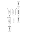
図1は、画像診断装置100の構成例を示す説明図である。本実施形態に係る画像診断装置100は、血管内超音波検査装置101と、血管造影装置102と、画像処理装置3と、表示装置4と、入力装置5とを備える。本実施形態に係る画像処理装置3は、血管(管腔器官)の3次元画像をアンギオ画像に重畳表示し、術者が血管の状態を直感的に把握し易くすることを可能にするものである。
<Overall configuration of image
1 is an explanatory diagram showing an example of the configuration of an image
血管内超音波検査装置101は、血管内超音波(IVUS: Intra Vascular Ultra Sound)法によって血管(管腔器官)の横断面である超音波断層像を含むIVUS画像(第1画像)を生成し、血管内の超音波検査及び診断を行うための装置である。血管内超音波検査装置101は、カテーテル1及びMDU(Motor Drive Unit)2を備える。
The intravascular
図2はカテーテル1の構成例を示す側断面図である。本実施形態に係るカテーテル1は、IVUS法によって血管の超音波断層像を得るための画像診断用カテーテルである。カテーテル1は、血管の超音波断層像を得るための超音波プローブ10を先端部に有する。超音波プローブ10は管部を有し、管部内にシャフト11が挿通している。シャフト11は管部に沿って進退可能であり、また、周方向に回転することができる。シャフト11の先端部には、血管内において超音波を発すると共に、血管の生体組織又は医用機器で反射された反射波(超音波エコー)を受信する超音波送受信部10aが設けられている。超音波プローブ10は、血管の周方向に回転しながら、血管の長手方向に進退可能に構成されている。
カテーテル1は、第1ガイドワイヤGW1が挿通するガイドワイヤルーメンを先端部に有する。ガイドワイヤルーメンにおける管部の中心線と、超音波プローブ10の管部の中心線とは所定長離隔している。
FIG. 2 is a side cross-sectional view showing an example of the configuration of the
The
また、カテーテル1は、血管内超音波検査装置101によって得られるIVUS画像と、血管造影装置102によって得られるアンギオ画像との位置関係を決定するため、X線を透過しない第1~第3マーカ11a,11b,11cを有する。第1~第3マーカ11a,11b,11cは、直線状に並ばないよう、非直線状に設けられている。例えば、第1マーカ11a及び第2マーカ11bは、超音波送受信部10aを挟んでシャフト11の先端部に設けられている。第3マーカ11cはガイドワイヤルーメンに設けられている。このように構成されたカテーテル1をX線で撮像すると、例えば図2下図のように第1~第3マーカ11a,11b,11cの画像を含むX線透視画像であるアンギオ画像が得られる。
なお、第1~第3マーカ11a,11b,11cを設ける位置は一例である。第1マーカ11a及び第2マーカ11bをシャフト11では無く、シャフト11が挿通する管部を有するカテーテル1本体に設けてもよい。つまり、シャフト11の位置に関係無く、第1~第3マーカ11a,11b,11cの位置が一定となるように設けてもよい。
The
The positions where the first to
MDU2は、カテーテル1が着脱可能に取り付けられる駆動装置であり、医療従事者の操作に応じて内蔵モータを駆動することにより、血管内に挿入されたカテーテル1の動作を制御する。MDU2は、カテーテル1の超音波送受信部10aを先端(遠位)側から基端(近位)側へ移動させながら周方向に回転させる(図8参照)。超音波プローブ10は、所定の時間間隔で連続的に血管内を走査し、検出された超音波の反射波データに基づくIVUS画像を画像処理装置3へ出力する。
The MDU 2 is a drive unit to which the
画像処理装置3は、カテーテル1の超音波プローブ10から出力された反射波データに基づいて、血管の横断層を撮像した超音波断層像を含む時系列順の複数のIVUS画像を生成する(図8参照)。超音波プローブ10は、血管内を先端(遠位)側から基端(近位)側へ移動しながら血管内を走査するため、時系列順の複数のIVUS画像は、遠位から近位にわたる複数箇所で観測された血管の断層画像ということになる。
Based on the reflected wave data output from the
血管造影装置102は、患者の血管に造影剤を注入しながら、患者の生体外からX線を用いて血管を撮像し、当該血管の透視画像であるアンギオ画像を得るための撮像装置である。血管造影装置102は、X線源及びX線センサを備え、X線源から照射されたX線をX線センサが受信することにより、患者のX線透視画像をイメージングする。血管造影装置102は、撮像して得られたアンギオ画像を画像処理装置3へ出力する。
The
血管造影装置102を用いて、カテーテル1が挿入された血管を撮像した場合、血管、カテーテル1、第1ガイドワイヤGW1の像を含むアンギオ画像が得られる。後述の第2ガイドワイヤGW2が血管に挿入されている場合、血管、カテーテル1、第1ガイドワイヤGW1、第2ガイドワイヤGW2の像を含むアンギオ画像が得られる。また、上記の通り、カテーテル1にはX線を透過しない第1~第3マーカ11a,11b,11cが設けられており、第1マーカ画像、第2マーカ画像及び第3マーカ画像を含むアンギオ画像が得られる。
When the
なお、本実施形態では主に2次元のアンギオ画像を撮像する血管造影装置102を例にして説明するが、生体外の複数の方向から患者の管腔器官及びカテーテル1を撮像する装置であれば、特に限定されるものではない。例えば、3次元CTアンギオグラフィ、磁気共鳴(MRI;Magnetic Resonance Imaging)画像などであってもよい。
In this embodiment, the
表示装置4は、液晶表示パネル、有機EL表示パネル等であり、画像処理装置3によって生成されたIVUS画像、アンギオ画像等の医用画像を表示する。
The
入力装置5は、検査を行う際の各種設定値の入力、画像処理装置3の操作等を受け付けるキーボード、マウス等の入力インターフェースである。入力装置5は、表示装置4に設けられたタッチパネル、ソフトキー、ハードキー等であっても良い。
The
<画像処理装置3のハードウェア構成>
図3は、画像処理装置3の構成例を示すブロック図である。画像処理装置3はコンピュータであり、制御部31、主記憶部32、入出力I/F33、及び補助記憶部34を備える。
<Hardware configuration of
3 is a block diagram showing an example of the configuration of the
制御部31は、一又は複数のCPU(Central Processing Unit)、MPU(Micro-Processing Unit)、GPU(Graphics Processing Unit)、GPGPU(General-purpose computing on graphics processing units)、TPU(Tensor Processing Unit)
等の演算処理装置を用いて構成されている。
The
The present invention is configured using a processor such as the above.
主記憶部32は、SRAM(Static Random Access Memory)、DRAM(Dynamic Random Access Memory)、フラッシュメモリ等の一時記憶領域であり、制御部31が演算処理を実行するために必要なデータを一時的に記憶する。
The
入出力I/F33は、血管内超音波検査装置101及び血管造影装置102、表示装置4及び入力装置5が接続されるインターフェースである。制御部31は、入出力I/F33を介して、IVUS画像又はアンギオ画像を取得する。また、制御部31は、入出力I/F33を介して、IVUS画像又はアンギオ画像の医用画像信号を表示装置4へ出力することによって、表示装置4に医用画像を表示する。更に、制御部31は、入出力I/F33を介して、入力装置5に入力された情報を受け付ける。
The input/output I/
補助記憶部34は、ハードディスク、EEPROM(Electrically Erasable Programmable ROM)、フラッシュメモリ等の記憶装置である。補助記憶部34は、制御部31が実行するコンピュータプログラムP、制御部31の処理に必要な各種データを記憶する。また、補助記憶部34は、学習モデル35を記憶する。学習モデル35の詳細は後述する。
The
なお、補助記憶部34は画像処理装置3に接続された外部記憶装置であってもよい。コンピュータプログラムPは、画像処理装置3の製造段階において補助記憶部34に書き込まれてもよいし、遠隔のサーバ装置が配信するものを画像処理装置3が通信にて取得して補助記憶部34に記憶させてもよい。コンピュータプログラムPは、磁気ディスク、光ディスク、半導体メモリ等の記録媒体30に読み出し可能に記録された態様であってもよい。
The
制御部31は、補助記憶部34に記憶されたコンピュータプログラムPを読み出して実行することにより、画像診断装置100で生成されたIVUS画像を取得し、CTO病変部位Cを有する血管の3次元画像を生成し、生成した3次元画像をアンギオ画像に写像して重畳表示する処理を実行する。
The
画像処理装置3は、複数のコンピュータを含んで構成されるマルチコンピュータであってよい。また、画像処理装置3は、サーバクライアントシステムや、クラウドサーバ、ソフトウェアによって仮想的に構築された仮想マシンであってもよい。以下の説明では、画像処理装置3が1台のコンピュータであるものとして説明する。
The
<CTO病変部位と、アンギオ画像及びIVUS画像の関係>
画像処理装置3の機能を説明する前に、慢性完全閉塞病変と、アンギオ画像及びIVUS画像との関係を説明する。
<Relationship between CTO lesion site and angio and IVUS images>
Before describing the functions of the
図4は血管の側断面を示す模式図である。図4に示す血管には、冠動脈が慢性的に完全に閉塞して血液が流れなくなってしまったCTO(Chronic Total Occlusion)病変部位Cが見られる。図4中、破線より右側の血管閉塞部位がCTO病変部位Cである。
CTO病変部位CのPCI治療においては、閉塞した血管における真腔Aの位置を把握してガイドワイヤを当該真腔Aに挿通する必要がある。ところで、PCIにおいては、順行性の第1ガイドワイヤGW1が、偽腔Bに迷入することがある。図4は、第1ガイドワイヤGW1が血管壁Vの偽腔Bに迷入した状態を示している。この場合、迷入した第1ガイドワイヤGW1に血管内超音波検査装置101のカテーテル1を挿入し、IVUS画像を得ることによって、血管壁V、真腔A及び偽腔Bの位置を確認することが行われる。術者は、真腔Aの位置を把握し、図4に示すように第2ガイドワイヤGW2をCTO病変部位C及び真腔Aに挿通させる。
ところが、IVUS画像及びアンギオ画像から真腔A及び偽腔Bの位置を把握することは容易ではない。
Fig. 4 is a schematic diagram showing a side cross section of a blood vessel. In the blood vessel shown in Fig. 4, a CTO (Chronic Total Occlusion) lesion site C is seen, in which the coronary artery is chronically and completely blocked, preventing blood flow. In Fig. 4, the vascular occlusion site to the right of the dashed line is the CTO lesion site C.
In PCI treatment of a CTO lesion site C, it is necessary to grasp the position of the true lumen A in an occluded blood vessel and insert a guidewire into the true lumen A. Meanwhile, in PCI, the antegrade first guidewire GW1 may stray into the false lumen B. FIG. 4 shows a state in which the first guidewire GW1 has strayed into the false lumen B of a blood vessel wall V. In this case, the
However, it is not easy to determine the positions of the true lumen A and false lumen B from IVUS images and angio images.
図5はIVUS画像とアンギオ画像の相違を示す説明図である。図5Aは血管の3次元イメージである。図5Bはアンギオ画像、図5CはIVUS画像の模式図である。
図5A及び図5Bに示すように、アンギオ画像は血管を横方向(径方向外側)から撮像して得られる透視画像であり、血管の走行を把握するには適している。しかし、造影剤はCTO病変部位Cを通過しないため、図5B中破線で示した部分の血管壁V、真腔A及び偽腔Bの像を得ることができない。カテーテル1及び第1ガイドワイヤGW1の像が見えるのみである。
一方、図5A及び図5Cに示すように、IVUS画像は血管の横断面像(血管の中心線に垂直な面で切った断面像)であり、CTO病変部位C、真腔A、偽腔B、カテーテル1、第1ガイドワイヤGW1の位置を確認することができる。また、図示しない第2ガイドワイヤGW2が存在する部位を撮像すれば、第2ガイドワイヤGW2の位置も確認することができる。しかし、IVUS画像は血管の横断面像であり、術者が頭の中で血管の3次元イメージを構築し、カテーテル1と、真腔Aとの位置関係を把握することは容易ではない。
5A and 5B are explanatory diagrams showing the difference between an IVUS image and an angio image. Fig. 5A is a three-dimensional image of a blood vessel. Fig. 5B is a schematic diagram of an angio image, and Fig. 5C is a schematic diagram of an IVUS image.
As shown in Figures 5A and 5B, an angio image is a fluoroscopic image obtained by imaging a blood vessel from the lateral direction (diametrically outward), and is suitable for understanding the course of the blood vessel. However, since the contrast agent does not pass through the CTO lesion site C, it is not possible to obtain images of the blood vessel wall V, true lumen A, and false lumen B in the portion indicated by the dashed line in Figure 5B. Only images of the
On the other hand, as shown in Figures 5A and 5C, an IVUS image is a cross-sectional image of a blood vessel (a cross-sectional image cut along a plane perpendicular to the center line of the blood vessel), and the positions of the CTO lesion site C, true lumen A, false lumen B,
また、IVUS画像は、カテーテル1の超音波プローブ10を周方向に回転させながら、超音波を発し、反射波を検出することにより得られる画像であり、上下左右方向は不定である。このため、図5C中白抜き矢印で示すように、アンギオ画像は、IVUS画像における血管をどの方向から撮像して得たものかが直ちに分かるものではない。異なる複数の方向から撮像したアンギオ画像を取得し、カテーテル1、第1ガイドワイヤGW1、第1~第3マーカ11a,11b,11cの画像から、術者はIVUS画像とアンギオ画像の位置関係を推定し、CTO病変部位Cにおける真腔Aの3次元イメージを頭の中で再構築する必要があり、容易なことではない。
In addition, an IVUS image is an image obtained by emitting ultrasound and detecting reflected waves while rotating the
そこで、本実施形態に係る画像処理装置3は、IVUS画像に基づいて、CTO病変部位Cの血管の3次元画像を生成し、アンギオ画像に当該3次元画像を写像して重畳して表示する処理を実行する。
Therefore, the
<画像処理装置3の機能ブロック図>
図6は画像処理装置3の機能ブロック図、図7はアンギオ画像に3次元画像が写像及び重畳された合成画像である。画像処理装置3の制御部31は、補助記憶部34が記憶するコンピュータプログラムPを読み出して実行することにより、認識部3a、三次元画像生成部3b、座標変換部3c、画像合成部3dとして機能する。
<Functional block diagram of
Fig. 6 is a functional block diagram of the
認識部3aは、学習モデル35を用いてIVUS画像に含まれる所定のオブジェクトを認識する処理を実行する。例えば、認識部3aは、IVUS画像に含まれる血管壁Vの画像、真腔Aの画像、偽腔Bの画像、カテーテル1の画像、第1ガイドワイヤGW1及び第2ガイドワイヤGW2の画像を認識する。認識部3aによって認識処理された画像は、オブジェクトの種類に応じた画素値を有する画像、つまりオブジェクトの種類に応じた画素値によってラベル付けされた画像(以下、ラベル付きIVUS画像と呼ぶ。)である。認識部3aは、複数のIVUS画像それぞれに対して認識処理を実行し、認識処理によって得られた複数のラベル付きIVUS画像を三次元画像生成部3bへ出力する。
The recognition unit 3a executes a process of recognizing a predetermined object included in the IVUS image using the
三次元画像生成部3bは、複数のラベル付きIVUS画像に基づいて、CTO病変部位Cの血管を表す3次元画像を生成し、生成した3次元画像を座標変換部3cへ出力する。3次元画像は、例えばボクセル法により生成することができる。3次元画像は、所定の座標系におけるボクセルの座標値と、オブジェクトの種類を示すボクセル値とで表されるボリュームデータで表される。なお、3次元画像のデータ形式は特に限定されるものではなく、ポリゴンデータ、点群データであってもよい。
The three-dimensional
座標変換部3cは、3次元画像をアンギオ画像における2次元座標系に座標変換し、座標変換された2次元画像を画像合成部3dへ出力する。座標変換の詳細は後述する。
The coordinate
画像合成部3dは、図7に示すように座標変換された血管の2次元画像をアンギオ画像に重畳させる合成処理を実行する。画像処理部は、血管の2次元画像を半透明にしてアンギオ画像に重畳させるとよい。つまり、座標変換部3c及び画像合成部3dの処理により、血管の3次元画像がアンギオ画像に写像され、重畳表示される。
The
<学習モデル35>
学習モデル35は、IVUS画像に含まれる所定のオブジェクトを認識するモデルである。学習モデル35は、例えば、セマンティックセグメンテーション(Semantic Segmentation)を用いた画像認識技術を利用することにより、オブジェクトを画素単位でクラス分けすることができ、IVUS画像に含まれるCTO病変部位C、具体的には血管壁V、真腔A、偽腔B、カテーテル1、第1ガイドワイヤGW1、第2ガイドワイヤGW2を認識することができる。
<
The
図8は、学習モデル35を用いた画像認識方法を示す説明図である。学習モデル35は、IVUS画像における血管壁V、真腔A、偽腔B、カテーテル1、第1ガイドワイヤGW1、第2ガイドワイヤGW2の画像を画素単位で認識できるように学習されている。
Figure 8 is an explanatory diagram showing an image recognition method using the
学習モデル35は、例えば深層学習による学習済みの畳み込みニューラルネットワーク(CNN:Convolutional neural network)である。学習モデル35は、いわゆるセマンティックセグメンテーションを用いた画像認識技術により、オブジェクトを画素単位で認識する。
学習モデル35は、IVUS画像が入力される入力層35aと、画像の特徴量を抽出し、復元する中間層35bと、IVUS画像に含まれるオブジェクトを画素単位で示すラベル付きIVUS画像を出力する出力層35cとを有する。学習モデル35は、例えばU-Netである。
The
The
学習モデル35の入力層35aは、IVUS画像に含まれる各画素の画素値の入力を受け付ける複数のニューロンを有し、入力された画素値を中間層35bに受け渡す。中間層35bは、畳み込み層(CONV層)と、逆畳み込み層(DECONV層)とを有する。畳み込み層は、画像データを次元圧縮する層である。次元圧縮により、オブジェクトの特徴量が抽出される。逆畳み込み層は逆畳み込み処理を行い、元の次元に復元する。逆畳み込み層における復元処理により、画像内の各画素が所定のオブジェクトであるか否かを、オブジェクトの種類に応じた画素値で表したラベル付きIVUS画像が生成される。出力層35cは、ラベル付きIVUS画像を出力する複数のニューロンを有する。ラベル付きIVUS画像は、例えば、血管壁Vに対応する画素がクラス「1」、真腔Aに対応する画素クラス「2」、偽腔Bに対応する画素クラス「3」、カテーテル1に対応する画素クラス「4」、第1及び第2ガイドワイヤGW1,GW2に対応する画素クラス「5」、その他の画像に対応する画素がクラス「0」の画像である。
The
学習モデル35は、血管壁V、カテーテル1、ガイドワイヤ、真腔A及び偽腔Bを含むIVUS画像と、当該IVUS画像における各オブジェクト画像を示すラベル付きIVUS画像とを有する訓練データを用意し、当該訓練データを用いて未学習のニューラルネットワークを機械学習させることにより生成することができる。具体的には、制御部31は、訓練データに含まれる複数のIVUS画像を学習前のニューラルネットワークモデルの入力層35aに入力し、中間層35bでの演算処理を経て、出力層35cから出力される画像を取得する。そして、制御部31は、出力層35cから出力された画像と、訓練データに含まれるラベル付きIVUS画像とを比較し、出力層35cから出力される画像がラベル付きIVUS画像に近づくように、中間層35bでの演算処理に用いるパラメータを最適化する。当該パラメータは、例えばニューロン間の重み(結合係数)などである。パラメータの最適化の方法は特に限定されないが、例えば制御部31は最急降下法、誤差逆伝播法等を用いて各種パラメータの最適化を行う。
The
このように学習された学習モデル35によれば、IVUS画像を学習モデル35に入力することによって、血管壁V、カテーテル1、ガイドワイヤ、真腔A及び偽腔Bを画素単位で示すラベル付きIVUS画像が得られる。
According to the
<3次元画像の座標変換及び重畳表示>
図9は座標変換方法を示す説明図である。以下、理解を容易にするため、固定された所定の3次元直交座標系である世界座標系を導入し、世界座標系を介して血管の三次元画像をアンギオ画像に写像するものとして説明する。図9中、黒丸は、第1~第3マーカ11a,11b,11cの画像を示している。なお、説明を簡単にするため、第1~第3マーカ11a,11b,11cの画像は、カテーテル1による血管走査前、つまりシャフト11移動前の各マーカの画像であるものとする。
<Coordinate conversion and superimposed display of 3D images>
Fig. 9 is an explanatory diagram showing the coordinate conversion method. In the following, for ease of understanding, a world coordinate system, which is a fixed, predetermined three-dimensional orthogonal coordinate system, is introduced, and a three-dimensional image of a blood vessel is mapped onto an angio image via the world coordinate system. In Fig. 9, black circles indicate images of the first to
図9中、右上に示すアンギオ画像は2次元のアンギオ座標系で表されるものとする。アンギオ座標系のXa軸及びYa軸は、例えば表示装置4に表示される画像の水平線(横軸)及び垂直線(縦軸)である。図9中、(xa,ya)は、アンギオ座標系におけるアンギオ画像を構成するピクセルの座標値である。
In FIG. 9, the angio image shown in the upper right is represented in a two-dimensional angio coordinate system. The Xa and Ya axes of the angio coordinate system are, for example, the horizontal line (horizontal axis) and vertical line (vertical axis) of the image displayed on the
アンギオ画像における第1~第3マーカ11a,11b,11c画像の位置は、撮像方向によって変化する。そこで、世界座標系における第1~第3マーカ11a,11b,11cの絶対的な位置を考える。世界座標系は任意の3次元直交座標系である。世界座標系の設定方法は任意であるが、例えば、血管造影装置102による撮像方向が原点であり、撮像方向がXw軸回りで変化するように設定すればよい。
The positions of the first to
血管走査前のカテーテル1に設けられた第1~第3マーカ11a,11b,11cの位置は固定的である。少なくとも、第1及び第2マーカ11a,11bの位置関係は一定であり、第1及び第2マーカ11a,11bを通る直線と、第3マーカ11cとの位置関係は一定である。
従って、複数の異なる撮像方向θから撮像して得られるアンギオ画像における第1~第3マーカ画像の座標位置より、世界座標系における第1~第3マーカ11a,11b,11cの座標位置(xw,yw,zw)を求めることができる。また、世界座標系の座標(xw,yw,zw)を、アンギオ座標系の座標(xa,ya,za)に変換する座標変換行列fwaを求めることができる。座標変換行列fwaは、回転行列、平行移動行列、正射影行列、拡大縮小行列等の積で表すことができる。座標変換行列fwaは、血管造影装置102による撮像方向θの関数で表すことができる。
Before vascular scanning, the positions of the first to
Therefore, the coordinate positions (xw, yw, zw) of the first to
一方、IVUS画像に基づいて生成される3次元画像はIVUS座標系にマッピングされる。IVUS座標系は、例えば3次元直交座標系である。IVUS座標系の取り方は任意である。例えば、第1マーカ及び第2マーカがZi軸を通り、第3マーカがXi軸を通るような3次元座標系が考えられる。具体的には、3次元画像におけるカテーテル1の中心線、言い換えると超音波を出力点の複数のボクセルのX座標値及びY座標値をゼロとし、3次元画像における第1ガイドワイヤGW1を構成するボクセルのうち、Z軸座標値がゼロのボクセルのY座標値がゼロとなるように、3次元座標をIVUS座標系にマッピングするとよい。図9中、(xi,yi,zi)は、IVUS座標系における3次元画像を構成するボクセルとの座標値である。
なお、超音波プローブ10が移動すると、第1マーカ及び第2マーカの位置が変化するが、第1マーカ及び第2マーカは常にZi軸上にあるため、問題無く一つのIVUS座標系に3次元画像をマッピングすることができる。
このように第1~第3マーカ11a,11b,11cの位置をIVUS座標系に合わせることにより、いわばカテーテル1を所定の向きに合わせるかのようにして3次元座標をIVUS座標系にマッピングすることができる。
On the other hand, the three-dimensional image generated based on the IVUS image is mapped to the IVUS coordinate system. The IVUS coordinate system is, for example, a three-dimensional orthogonal coordinate system. The IVUS coordinate system can be arbitrarily taken. For example, a three-dimensional coordinate system in which the first marker and the second marker pass through the Zi axis and the third marker passes through the Xi axis can be considered. Specifically, the three-dimensional coordinates may be mapped to the IVUS coordinate system so that the X-coordinate value and the Y-coordinate value of the center line of the
When the
By aligning the positions of the first to
上記の通りIVUS座標系における第1~第3マーカ11a,11b,11cの位置は既知であり、世界座標系における第1~第3マーカ11a,11b,11cの座標位置も求められているため、IVUS座標系の座標(xi,yi,zi)を世界座標系の座標(xw,yw,zw)に変換する座標変換行列fiwを求めることができる。この座標変換行列fiwは回転行列、平行移動行列及び拡大縮小行列の積で表すことができる。
As described above, the positions of the first to
結局、IVUS座標系における3次元画像を、アンギオ座標系へ写像する座標変換行列fiaは、座標変換行列fiwと座標変換行列fwaの積で表すことができる。 In the end, the coordinate transformation matrix fia that maps a three-dimensional image in the IVUS coordinate system to the angio coordinate system can be expressed as the product of the coordinate transformation matrix fiw and the coordinate transformation matrix fwa.
<座標変換行列の導出処理>
図10は座標変換行列fiaの作成方法を示す説明図、図11は座標変換行列の作成処理手順を示すフローチャートである。制御部31は、血管造影装置102により複数の異なる撮像方向θから撮像して得られたアンギオ画像及び撮像方向θを取得する(ステップS11)。次いで、制御部31は所定数方向からアンギオ画像を撮像したか否かを判定する(ステップS12)。所定数は2以上であるが、撮像方向が多い程、座標変換行列の精度、つまり、血管の3次元画像をアンギオ画像に写像する精度が高くなる。
<Process of deriving coordinate transformation matrix>
Fig. 10 is an explanatory diagram showing a method for creating the coordinate transformation matrix fia, and Fig. 11 is a flowchart showing a process for creating the coordinate transformation matrix. The
所定数方向から撮像したアンギオ画像が得られていない場合(ステップS12:NO)、制御部31は、血管造影装置102へ撮像方向の変更を指示する信号を出力して撮像方向θを変更させ(ステップS13)、処理をステップS11へ戻す。なお、血管造影装置102が自動的に撮像方向θを連続的に変化させている場合、ステップS13の処理は不要である。
なお、ステップS11~ステップS13の処理を実行する制御部31は、生体外の異なる複数の方向から血管(管腔器官)及びカテーテル1を撮像した複数のアンギオ画像(第2画像)を取得する第2取得部として機能する。
If angiographic images captured from the predetermined number of directions have not been obtained (step S12: NO), the
In addition, the
所定数方向から撮像した複数のアンギオ画像が得られた場合(ステップS12:YES)、制御部31は、複数の異なる撮像方向θから撮像して得た複数のアンギオ画像における第1~第3マーカ11a,11b,11cの座標値及び撮像方向θを用いて、座標変換行列fiaを算出し(ステップS14)、処理を終える。
なお、ステップS14の処理を実行する制御部31は、取得した複数のアンギオ画像(第2画像)に基づいて、IVUS画像(第1画像)及びアンギオ画像(第2画像)の位置関係を特定する特定部として機能する。
When multiple angio images captured from a predetermined number of directions have been obtained (step S12: YES), the
In addition, the
分解して考えると、世界座標系における第1~第3マーカ11a,11b,11cの座標値が求まれば、IVUS座標系から世界座標系への座標変換行列fiwが求まる。また、世界座標系における第1~第3マーカ11a,11b,11cの座標値が求まれば、制御部31は、世界座標系からアンギオ座標系への座標変換行列fwa(θの関数)により得られる第1~第3マーカ画像の座標値と、撮像方向θから撮像して得られたアンギオ画像における第1~第3マーカ画像の座標値とが整合するように、例えば最尤推定法により、座標変換行列fwaを求めることができる。そして、座標変換行列fiwと座標変換行列fwaとの積を求めれば、IVUS座標系における3次元画像を、アンギオ座標系に写像する座標変換行列fiaを求めることができる。
Breaking it down, once the coordinate values of the first to
なお、アンギオ座標系に写像される血管の画像は、血管の位置、大きさ、3次元空間における向き及び傾きが全て反映された2次元画像であるため、この2次元画像をアンギオ画像に重畳させることにより、術者はアンギオ画像における血管の3次元構造を容易に理解することができる。 In addition, the image of the blood vessels mapped onto the angio coordinate system is a two-dimensional image that reflects the position, size, orientation and inclination of the blood vessels in three-dimensional space. By superimposing this two-dimensional image on the angio image, the surgeon can easily understand the three-dimensional structure of the blood vessels in the angio image.
<3次元画像生成及び重畳表示処理>
図12は画像処理手順を示すフローチャートである。画像処理装置3は、学習済みの学習モデル35と、図11の処理で座標変換行列を作成済みであるものとして説明する。
<3D image generation and superimposed display processing>
12 is a flowchart showing the image processing procedure. The
制御部31は、血管内超音波検査装置101から出力される複数のIVUS画像を取得する(ステップS31)。なお、ステップS31の処理を実行する制御部31は、カテーテルを用いて血管(管腔器官)の横断面を複数箇所で撮像した複数のIVUS画像(第1画像)を取得する第1取得部として機能する。
The
次いで、制御部31は、取得したIVUS画像を学習モデル35に入力することによって、IVUS画像に含まれるオブジェクトを認識する(ステップS32)。そして、制御部31は、ステップS32のオブジェクトの認識処理によって得られたラベル付きIVUS画像に基づいて血管が3次元画像を生成する(ステップS33)。3次元画像は、例えば、血管壁V、真腔A、偽腔B、カテーテル1、第1ガイドワイヤGW1及び第2ガイドワイヤGW2を3次元的に表した画像である。
なお、ステップS31及びステップS33の処理を実行する制御部31は、取得した複数のIVUS画像(第1画像)に基づいて、血管(管腔器官)の3次元画像を生成する生成部として機能する。
Next, the
The
そして、制御部31は、血管造影装置102からアンギオ画像と、撮像方向θとを取得する(ステップS34)。制御部31は、撮像方向θにより座標変換行列を求め、当該座標変換行列を用いて、IVUS座標系における3次元画像を、アンギオ座標系の2次元画像に変換し(ステップS35)、アンギオ座標系に写像された血管の2次元画像を、アンギオ画像に重畳させ(ステップS36)、血管の3次元画像をアンギオ画像に写像して得られた合成画像を表示処理に表示する(ステップS37)。
なお、ステップS35及びステップS36の処理を実行する制御部31は、特定された位置関係に基づいて、3次元画像をアンギオ画像(第2画像)に写像して重畳表示する重畳表示部として機能する。
The
The
次いで、制御部31は、処理を終了するか否かを判定する(ステップS38)。終了すると判定した場合(ステップS38:YES)、制御部31は血管の3次元画像の重畳処理を終了する。終了しないと判定した場合(ステップS38:NO)、制御部31は処理をステップS34へ戻す。
Next, the
以上の通り、本実施形態に係る画像処理装置3等によれば、血管の3次元画像をアンギオ画像に写像して重畳表示することができる。術者が血管の状態を直感的に把握し易くすることができる。
As described above, the
また、カテーテル1に設けられた第1~第3マーカ11a,11b,11cの座標値に基づいて、座標変換行列を求めることにより、血管の3次元画像を精度良くアンギオ画像に写像し、重畳表示させることができる。
In addition, by calculating a coordinate transformation matrix based on the coordinate values of the first to
更に、IVUS画像に含まれる血管壁V、真腔A、偽腔B、カテーテル1、第1ガイドワイヤGW1及び第2ガイドワイヤGW2を認識して3次元画像を生成し、アンギオ画像に写像して重畳表示させることができる。従って、術者は、アンギオ画像における血管壁V、真腔A、偽腔B、カテーテル1の位置を容易に認識することができる。
また、画像処理装置3は、3次元画像に含まれる各オブジェクトを透明画像としてアンギオ画像に写像して重畳表示させる構成であるため、アンギオ画像の画像と、IVUS画像に基づく血管の真腔A及び偽腔B等のオブジェクトの関係をより正確に把握することができる。
Furthermore, the vascular wall V, true lumen A, false lumen B,
Furthermore, since the
更にまた、ステップS34~ステップS37の処理を繰り返し実行することにより、時系列的にアンギオ画像及び撮像方向θを取得し、都度、撮像方向θに応じた座標変換画像を求め、三次元画像を、時系列順に取得される当該アンギオ画像に重畳表示させることができる。撮像方向θの変換によってアンギオ画像における血管の位置が変化しても、血管の位置変換に追従するように、3次元画像を該当位置に写像して重畳させることができる。 Furthermore, by repeatedly executing the processes of steps S34 to S37, it is possible to acquire angio images and imaging directions θ in chronological order, obtain coordinate transformed images according to the imaging direction θ each time, and superimpose a three-dimensional image on the angio images acquired in chronological order. Even if the position of the blood vessel in the angio image changes due to transformation of the imaging direction θ, the three-dimensional image can be mapped and superimposed at the corresponding position so as to follow the transformation of the blood vessel position.
なお、画像処理装置3は、IVUS画像に含まれる血管壁V、真腔A、偽腔B、カテーテル1、第1ガイドワイヤGW1及び第2ガイドワイヤGW2等のオブジェクトを全てアンギオ画像に重畳させる必要は無く、表示するオブジェクトをユーザから受け付けるように構成してもよい。画像処理装置3は、受け付けた表示対象のオブジェクトを含む3次元画像を生成する。具体的には、制御部31は、ラベル付きIVUS画像から、表示対象外のオブジェクトのクラスが付された画素値をゼロに設定することによって、表示対象のオブジェクトのみを含むラベル付きIVUS画像を得ることができる。制御部31は、表示対象のオブジェクトのみを含むラベル付きIVUS画像に基づいて、表示対象を表した3次元画像を得ることができる。例えば、制御部31は、血管壁Vと、真腔Aのみを表した3次元画像を生成し、アンギオ画像に写像し、重畳させることができる。
The
また、アンギオ画像に重畳させる画像のオブジェクトの内容を示す文字、記号等をアンギオ画像に重畳表示させるように構成してもよい。更に、オブジェクトの種類毎に、異なる色の透明画像をアンギオ画像に重畳させるように構成してもよい。 Also, the system may be configured to superimpose characters, symbols, etc., indicating the contents of the object of the image to be superimposed on the angio image on the angio image. Furthermore, the system may be configured to superimpose transparent images of different colors on the angio image for each type of object.
(変形例1)
また、本実施形態では、カテーテル1に設けられた第1~第3マーカ11a,11b,11cによって、座標変換行列を求める例を説明したが、これに限定されるものではない。例えば、制御部31は、カテーテル1に設けられた第1マーカ11a及び第2マーカ11bのマーカ画像と、第1ガイドワイヤGW1又は第2ガイドワイヤGW2の先端部の画像とに基づいて、座標変換行列を求めてもよい。各座標の関係を特定するための基準が異なるのみであり、実施形態で説明した方法で座標変換行列を算出することができる。
その他、血管造影装置102によって撮像することができ、かつ3次元空間における位置及び姿勢を特定することができる3点以上の部位であれば、マーカの設定方法は特に限定されるものではない。
(Variation 1)
In addition, in the present embodiment, an example has been described in which a coordinate transformation matrix is calculated using the first to
In addition, the method of setting the markers is not particularly limited as long as the markers are three or more points that can be imaged by the
(変形例2)
更に、実施形態では、血管造影装置102からアンギオ画像と共に撮像方向θの情報を取得する例を説明したが、撮像方向θは必須の情報ではない。制御部31は、撮像方向θを用いずに座標変換行列を求めるようにしてもよい。制御部31は、異なる複数の撮像方向θから得られる複数のアンギオ画像に含まれる第1~第3マーカ画像の位置が分かれば、撮像方向θの相対的な変化を求めることができる。制御部31は、一のアンギオ画像が撮像された撮像方向を基準方向とし、他のアンギオ画像が得られる撮像方向を当該基準方向からの相対角度で表すことができる。この相対角度は、2枚のアンギオ画像から求めることができ、座標変換行列をこの相対角度によって表現すれば、血管造影装置102から撮像方向θの情報を得ることなく、血管の3次元画像をアンギオ画像に写像し、重畳させることができる。
(Variation 2)
Furthermore, in the embodiment, an example has been described in which information on the imaging direction θ is obtained from the
1 カテーテル
3 画像処理装置
3a 認識部
3b 三次元画像生成部
3c 座標変換部
3d 画像合成部
4 表示装置
5 入力装置
10 超音波プローブ
11 シャフト
10a 超音波送受信部
31 制御部
35 学習モデル
P コンピュータプログラム
A 真腔
B 偽腔
C CTO病変部位
V 血管壁
GW1 第1ガイドワイヤ
GW2 第2ガイドワイヤ
100 画像診断装置
101 血管内超音波検査装置
102 血管造影装置
REFERENCE SIGNS
Claims (9)
取得した複数の第1画像に含まれる真腔又は偽腔の画像を認識し、
認識した真腔又は偽腔の前記画像に基づいて、少なくとも前記血管における真腔又は偽腔を表現した3次元画像を生成し、
生体外の異なる複数の方向から前記血管及び前記カテーテルを撮像した複数の第2画像を取得し、
取得した複数の第2画像に基づいて、第1画像及び第2画像の位置関係を特定し、
特定された位置関係に基づいて、前記3次元画像を前記第2画像に写像して重畳表示する
処理をコンピュータに実行させるコンピュータプログラム。 A plurality of first images are obtained by capturing images of a cross section of a blood vessel at a plurality of locations using a catheter;
Recognizing an image of the true lumen or false lumen included in the acquired plurality of first images;
generating a three-dimensional image representing at least the true lumen or false lumen in the blood vessel based on the image of the recognized true lumen or false lumen;
acquiring a plurality of second images of the blood vessel and the catheter taken from a plurality of different directions outside the living body;
Identifying a positional relationship between the first image and the second image based on the acquired plurality of second images;
A computer program that causes a computer to execute a process of mapping the three-dimensional image onto the second image and displaying the image in a superimposed manner based on the specified positional relationship.
取得した複数の第2画像における前記マーカ画像に基づいて、第1画像及び第2画像の位置関係を特定する
処理を前記コンピュータに実行させる請求項1に記載のコンピュータプログラム。 the second image includes a marker image obtained by capturing an image of a marker provided on the catheter,
The computer program product according to claim 1 , further comprising: determining a positional relationship between the first image and the second image based on the marker images in the acquired second images.
取得した複数の第2画像それぞれに含まれる複数のマーカ画像に基づいて、第1画像及び第2画像の位置関係を特定する
処理を前記コンピュータに実行させる請求項1又は請求項2に記載のコンピュータプログラム。 the second image includes a plurality of marker images obtained by imaging three or more markers that are provided on the catheter and positioned on a non-linear line,
The computer program product according to claim 1 or 2, which causes the computer to execute a process of identifying a positional relationship between the first image and the second image based on a plurality of marker images included in each of the plurality of acquired second images.
取得した複数の第2画像それぞれに含まれる前記複数のマーカ画像及び前記ガイドワイヤの画像に基づいて、第1画像及び第2画像の位置関係を特定する
処理を前記コンピュータに実行させる請求項1又は請求項2に記載のコンピュータプロ
グラム。 The second image includes a plurality of marker images obtained by capturing images of a plurality of markers provided on the catheter, and an image of a guidewire,
The computer program according to claim 1 or 2, which causes the computer to execute a process of identifying a positional relationship between the first image and the second image based on the plurality of marker images and the image of the guide wire included in each of the plurality of acquired second images.
第1画像と、取得した第2画像との位置関係を順次特定し、
特定された位置関係に基づいて、前記3次元画像を時系列的に取得した各第2画像に順次、写像して重畳表示する
処理を前記コンピュータに実行させる請求項1~請求項4のいずれか1項に記載のコンピュータプログラム。 acquiring second images in a time series;
sequentially identifying a positional relationship between the first image and the acquired second image;
The computer program according to any one of claims 1 to 4, which causes the computer to execute a process of sequentially mapping and superimposing the three-dimensional image on each of the second images acquired in a time series based on the specified positional relationship.
処理を前記コンピュータに実行させる請求項1~請求項5のいずれか1項に記載のコンピュータプログラム。 The computer program according to any one of claims 1 to 5, which causes the computer to execute a process of recognizing an image of a true lumen or a false lumen contained in a first image by inputting the acquired first image into a learning model that recognizes an image of a true lumen or a false lumen contained in the image.
認識した前記ガイドワイヤの画像に基づいて、前記ガイドワイヤを表現した3次元画像を生成する
処理を前記コンピュータに実行させる請求項1~請求項6のいずれか1項に記載のコンピュータプログラム。 Recognizing an image of the guidewire included in the acquired plurality of first images;
The computer program according to any one of claims 1 to 6, which causes the computer to execute a process of generating a three-dimensional image representing the guidewire based on the recognized image of the guidewire.
取得した複数の第1画像に含まれる真腔又は偽腔の画像を認識し、
認識した真腔又は偽腔の前記画像に基づいて、少なくとも前記血管における真腔又は偽腔を表現した3次元画像を生成し、
生体外の異なる複数の方向から前記血管及び前記カテーテルを撮像した複数の第2画像を取得し、
取得した複数の第2画像に基づいて、第1画像及び第2画像の位置関係を特定し、
特定された位置関係に基づいて、前記3次元画像を前記第2画像に写像して重畳表示する
処理をコンピュータが実行する画像処理方法。 A plurality of first images are obtained by capturing images of a cross section of a blood vessel at a plurality of locations using a catheter;
Recognizing an image of the true lumen or false lumen included in the acquired plurality of first images;
generating a three-dimensional image representing at least the true lumen or false lumen in the blood vessel based on the image of the recognized true lumen or false lumen;
acquiring a plurality of second images of the blood vessel and the catheter taken from a plurality of different directions outside the living body;
Identifying a positional relationship between the first image and the second image based on the acquired plurality of second images;
based on the specified positional relationship, the three-dimensional image is mapped onto the second image and displayed in a superimposed manner.
取得した複数の第1画像に含まれる真腔又は偽腔の画像を認識する認識部と、
認識した真腔又は偽腔の前記画像に基づいて、少なくとも前記血管における真腔又は偽腔を表現した3次元画像を生成する生成部と、
生体外の異なる複数の方向から前記血管及び前記カテーテルを撮像した複数の第2画像を取得する第2取得部と
取得した複数の第2画像に基づいて、第1画像及び第2画像の位置関係を特定する特定部と、
特定された位置関係に基づいて、前記3次元画像を前記第2画像に写像して重畳表示する重畳表示部と
を備える画像処理装置。 a first acquisition unit that acquires a plurality of first images by capturing images of a cross section of a blood vessel at a plurality of locations using a catheter;
a recognition unit that recognizes an image of a true lumen or a false lumen included in the acquired plurality of first images;
a generating unit that generates a three-dimensional image representing at least the true lumen or false lumen in the blood vessel based on the image of the recognized true lumen or false lumen;
a second acquisition unit that acquires a plurality of second images obtained by capturing images of the blood vessel and the catheter from a plurality of different directions outside the living body; and a determination unit that determines a positional relationship between the first image and the second image based on the acquired plurality of second images.
and a superimposition display unit that maps the three-dimensional image onto the second image and displays the three-dimensional image superimposed on the second image based on the specified positional relationship.
Priority Applications (1)
| Application Number | Priority Date | Filing Date | Title |
|---|---|---|---|
| JP2020162616A JP7489882B2 (en) | 2020-09-28 | 2020-09-28 | Computer program, image processing method and image processing device |
Applications Claiming Priority (1)
| Application Number | Priority Date | Filing Date | Title |
|---|---|---|---|
| JP2020162616A JP7489882B2 (en) | 2020-09-28 | 2020-09-28 | Computer program, image processing method and image processing device |
Publications (2)
| Publication Number | Publication Date |
|---|---|
| JP2022055170A JP2022055170A (en) | 2022-04-07 |
| JP7489882B2 true JP7489882B2 (en) | 2024-05-24 |
Family
ID=80997923
Family Applications (1)
| Application Number | Title | Priority Date | Filing Date |
|---|---|---|---|
| JP2020162616A Active JP7489882B2 (en) | 2020-09-28 | 2020-09-28 | Computer program, image processing method and image processing device |
Country Status (1)
| Country | Link |
|---|---|
| JP (1) | JP7489882B2 (en) |
Families Citing this family (2)
| Publication number | Priority date | Publication date | Assignee | Title |
|---|---|---|---|---|
| JP2023176250A (en) * | 2022-05-31 | 2023-12-13 | 朝日インテック株式会社 | Surgical operation support device, surgical operation support method and computer program |
| WO2024042823A1 (en) * | 2022-08-23 | 2024-02-29 | 株式会社島津製作所 | X-ray imaging device |
Citations (5)
| Publication number | Priority date | Publication date | Assignee | Title |
|---|---|---|---|---|
| JP2013183875A (en) | 2012-03-07 | 2013-09-19 | Toshiba Corp | Ultrasonic diagnostic apparatus and ultrasonic diagnosis assisting method |
| WO2014136137A1 (en) | 2013-03-04 | 2014-09-12 | テルモ株式会社 | Diagnostic imaging apparatus, information processing device and control methods, programs and computer-readable storage media therefor |
| US20140275996A1 (en) | 2013-03-12 | 2014-09-18 | Volcano Corporation | Systems and methods for constructing an image of a body structure |
| CN104068897A (en) | 2014-06-17 | 2014-10-01 | 汝磊生 | Intravascular ultrasound double-cavity micro-catheter |
| JP2017153621A (en) | 2016-02-29 | 2017-09-07 | テルモ株式会社 | Medical device |
-
2020
- 2020-09-28 JP JP2020162616A patent/JP7489882B2/en active Active
Patent Citations (5)
| Publication number | Priority date | Publication date | Assignee | Title |
|---|---|---|---|---|
| JP2013183875A (en) | 2012-03-07 | 2013-09-19 | Toshiba Corp | Ultrasonic diagnostic apparatus and ultrasonic diagnosis assisting method |
| WO2014136137A1 (en) | 2013-03-04 | 2014-09-12 | テルモ株式会社 | Diagnostic imaging apparatus, information processing device and control methods, programs and computer-readable storage media therefor |
| US20140275996A1 (en) | 2013-03-12 | 2014-09-18 | Volcano Corporation | Systems and methods for constructing an image of a body structure |
| CN104068897A (en) | 2014-06-17 | 2014-10-01 | 汝磊生 | Intravascular ultrasound double-cavity micro-catheter |
| JP2017153621A (en) | 2016-02-29 | 2017-09-07 | テルモ株式会社 | Medical device |
Also Published As
| Publication number | Publication date |
|---|---|
| JP2022055170A (en) | 2022-04-07 |
Similar Documents
| Publication | Publication Date | Title |
|---|---|---|
| US10687777B2 (en) | Vascular data processing and image registration systems, methods, and apparatuses | |
| EP3003161B1 (en) | Method for 3d acquisition of ultrasound images | |
| US8295577B2 (en) | Method and apparatus for guiding a device in a totally occluded or partly occluded tubular organ | |
| CN108633312B (en) | Contrast cloud detection method in X-ray image | |
| US8126241B2 (en) | Method and apparatus for positioning a device in a tubular organ | |
| US8126239B2 (en) | Registering 2D and 3D data using 3D ultrasound data | |
| EP2967480B1 (en) | Vascular data processing and image registration methods | |
| JP5685605B2 (en) | System for navigating an interventional device and its operating method, computer program element and computer readable medium | |
| JP2022517581A (en) | Methods and systems for providing a dynamic roadmap of coronary arteries | |
| JP2018519019A (en) | Intravascular imaging system interface and shadow detection method | |
| JP2007536973A (en) | Information-enhanced image-guided intervention | |
| JP7489882B2 (en) | Computer program, image processing method and image processing device | |
| CN114126491B (en) | Assessment of coronary artery calcification in angiographic images | |
| US20230020596A1 (en) | Computer program, information processing method, information processing device, and method for generating model | |
| US20240013385A1 (en) | Medical system, method for processing medical image, and medical image processing apparatus | |
| WO2008050315A2 (en) | Method and apparatus for guiding a device in a totally occluded or partly occluded tubular organ | |
| WO2022209652A1 (en) | Computer program, information processing method, and information processing device | |
| WO2022202323A1 (en) | Program, information processing method, and information processing device | |
| US20230017334A1 (en) | Computer program, information processing method, and information processing device | |
| WO2023100838A1 (en) | Computer program, information processing device, information processing method, and training model generation method | |
| US20230260120A1 (en) | Information processing device, information processing method, and program | |
| US20220028079A1 (en) | Diagnosis support device, diagnosis support system, and diagnosis support method | |
| WO2022071325A1 (en) | Information processing device, information processing method, program, and trained model generation method | |
| US20230042524A1 (en) | Program, information processing method, method for generating learning model, method for relearning learning model, and information processing system | |
| CN116894865A (en) | Provision of result data sets |
Legal Events
| Date | Code | Title | Description |
|---|---|---|---|
| A621 | Written request for application examination |
Free format text: JAPANESE INTERMEDIATE CODE: A621 Effective date: 20230410 |
|
| A977 | Report on retrieval |
Free format text: JAPANESE INTERMEDIATE CODE: A971007 Effective date: 20231110 |
|
| A131 | Notification of reasons for refusal |
Free format text: JAPANESE INTERMEDIATE CODE: A131 Effective date: 20231128 |
|
| A521 | Request for written amendment filed |
Free format text: JAPANESE INTERMEDIATE CODE: A523 Effective date: 20240123 |
|
| TRDD | Decision of grant or rejection written | ||
| A01 | Written decision to grant a patent or to grant a registration (utility model) |
Free format text: JAPANESE INTERMEDIATE CODE: A01 Effective date: 20240507 |
|
| A61 | First payment of annual fees (during grant procedure) |
Free format text: JAPANESE INTERMEDIATE CODE: A61 Effective date: 20240514 |
|
| R150 | Certificate of patent or registration of utility model |
Ref document number: 7489882 Country of ref document: JP Free format text: JAPANESE INTERMEDIATE CODE: R150 |