EP4129120A1 - Hanging device - Google Patents
Hanging device Download PDFInfo
- Publication number
- EP4129120A1 EP4129120A1 EP22166632.4A EP22166632A EP4129120A1 EP 4129120 A1 EP4129120 A1 EP 4129120A1 EP 22166632 A EP22166632 A EP 22166632A EP 4129120 A1 EP4129120 A1 EP 4129120A1
- Authority
- EP
- European Patent Office
- Prior art keywords
- main body
- assembly
- transportation
- accommodation main
- hanging device
- Prior art date
- Legal status (The legal status is an assumption and is not a legal conclusion. Google has not performed a legal analysis and makes no representation as to the accuracy of the status listed.)
- Granted
Links
Images




Classifications
-
- B—PERFORMING OPERATIONS; TRANSPORTING
- B66—HOISTING; LIFTING; HAULING
- B66C—CRANES; LOAD-ENGAGING ELEMENTS OR DEVICES FOR CRANES, CAPSTANS, WINCHES, OR TACKLES
- B66C17/00—Overhead travelling cranes comprising one or more substantially horizontal girders the ends of which are directly supported by wheels or rollers running on tracks carried by spaced supports
- B66C17/04—Overhead travelling cranes comprising one or more substantially horizontal girders the ends of which are directly supported by wheels or rollers running on tracks carried by spaced supports with lifting beams, e.g. slewable beams, carrying load-engaging elements, e.g. magnets, hooks
-
- B—PERFORMING OPERATIONS; TRANSPORTING
- B66—HOISTING; LIFTING; HAULING
- B66C—CRANES; LOAD-ENGAGING ELEMENTS OR DEVICES FOR CRANES, CAPSTANS, WINCHES, OR TACKLES
- B66C1/00—Load-engaging elements or devices attached to lifting or lowering gear of cranes or adapted for connection therewith for transmitting lifting forces to articles or groups of articles
- B66C1/10—Load-engaging elements or devices attached to lifting or lowering gear of cranes or adapted for connection therewith for transmitting lifting forces to articles or groups of articles by mechanical means
- B66C1/22—Rigid members, e.g. L-shaped members, with parts engaging the under surface of the loads; Crane hooks
- B66C1/28—Duplicate, e.g. pivoted, members engaging the loads from two sides
-
- B—PERFORMING OPERATIONS; TRANSPORTING
- B66—HOISTING; LIFTING; HAULING
- B66C—CRANES; LOAD-ENGAGING ELEMENTS OR DEVICES FOR CRANES, CAPSTANS, WINCHES, OR TACKLES
- B66C1/00—Load-engaging elements or devices attached to lifting or lowering gear of cranes or adapted for connection therewith for transmitting lifting forces to articles or groups of articles
- B66C1/10—Load-engaging elements or devices attached to lifting or lowering gear of cranes or adapted for connection therewith for transmitting lifting forces to articles or groups of articles by mechanical means
- B66C1/22—Rigid members, e.g. L-shaped members, with parts engaging the under surface of the loads; Crane hooks
- B66C1/34—Crane hooks
Definitions
- the present invention relates to a hanging device.
- the hanging device tends to shake when the hook of the hanging device is moving back and forth relative to the object that is to be hung or when the hook of the hanging device moves to the lowest position. Therefore, hook shaking and colliding with the object that is to be hung would be inevitable even if the operators accurately catch the positional relation between the hanging device and the object that is to be hung.
- a hanging device including an accommodation main body, a sliding assembly, and a hook.
- the accommodation main body has two parallel sidewalls which define a first vertical path between the two sidewalls.
- the sliding assembly is movably connected between the two sidewalls and configured to move relative to the accommodation main body along the first vertical path, in which the sliding assembly further includes a sliding rail which defines a second vertical path.
- the hook is movably connected to the sliding rail and configured to move relative to the sliding assembly along the second vertical path.
- the hanging device includes a transportation assembly connected to the accommodation main body and configured to drive the accommodation main body to move along a horizontal plane direction.
- the hanging device includes a transportation assembly including a transportation rail and a transportation rod, in which the transportation rod is movably connected to the transportation rail and configured to move relative to the transportation rail along a first horizontal axis.
- the accommodation main body is movably connected to the transportation rod and configured to move relative to the transportation rod along a second horizontal axis, and the first horizontal axis is substantially perpendicular to the second horizontal axis.
- the hanging device includes a rotating assembly connected between the accommodation main body and the transportation assembly, in which the accommodation main body is configured to rotate relative to the transportation assembly around a vertical axis.
- the hanging device further includes a fixing rod disposed on the accommodation main body, and the fixing rod is configured to move outside of the positioning groove of the rotating assembly such that the rotating assembly is in a rotatable state.
- the fixing rod is further configured to move into a positioning groove of the rotating assembly such that the rotating assembly is in a locking state.
- the hanging device includes an elastic portion and a stopping portion
- the fixing rod is configured to move outside of the positioning groove such that the stopping portion and the accommodation main body collectively press the elastic portion.
- the fixing rod is configured to move into the positioning groove such that the stopping portion and the accommodation main body collectively release the elastic portion.
- the positioning groove includes a plurality of positioning grooves which are arranged to surround a rotation axis of the rotating assembly.
- the hanging device further includes a pulley assembly which is disposed on the accommodation main body and configured to drive the hook to move relative to the accommodation main body.
- the hanging device further includes a pulley assembly which is disposed on the accommodation main body, and the pulley assembly includes a first pulley and a second pulley, a drive belt, and a rotary handle.
- the first pulley and the second pulley are coaxially connected, and the drive belt is fastened to the first pulley and the rotary handle.
- the rotary handle is configured to drive the first pulley, so as to drive the hook to vertically move relative to the accommodation main body.
- a hanging device including an accommodation main body, a sliding assembly, a hook, and a transportation assembly.
- the accommodation main body has two parallel sidewalls which define a first vertical path between the two sidewalls.
- the sliding assembly is movably connected between the two sidewalls and configured to move relative to the accommodation main body along the first vertical path, and the sliding assembly further includes a sliding rail which defines a second vertical path.
- the hook is movably connected to the sliding rail and configured to move relative to the sliding assembly along the second vertical path.
- the transportation assembly is connected to the accommodation main body and configured to drive the accommodation main body to move along a horizontal plane direction.
- Hooks of general hanging devices do not have enough degrees of freedom regarding movement and rotation, so it is hard to hang an object located at an edge or a corner due to the dead angle of the hooks when the operators operates the hanging devices. Also, the hooks of general hanging devices are easy to shake and cause danger when they are extended for too long.
- Embodiments of the present invention provide a hanging device having more degrees of freedom regarding movement and rotation and also improving the stability for hanging and lifting an object. Especially, the hanging device has a wider hanging operation area to be benefit for reducing the dead angle, so as to help the operators to stably hang and lift an object located at an edge or a corner.
- the hanging device of the present invention includes a vertical path in two sections to stably lift or lower the hook for grabbing an object.
- the hanging device of the present invention further includes a transportation assembly for moving the hook along two horizontal axes which are perpendicular to each other. Furthermore, the hanging device of the present invention further includes a rotating assembly which is configured to rotate the hook around a vertical axis. Therefore, the hook can not only freely move in three-dimensional directions but also rotate freely, and the hanging device of the present invention can use the hook to grab objects under a great degree of freedom, so as to decrease the blind spot about the hanging operation.
- Fig. 12 illustrates a rear view of a hanging device in accordance with some embodiments of the present invention, and a partial housing of a rotary handle is not shown.
- a hanging device 100 includes an accommodation main body 110, a sliding assembly 120, and a hook 130.
- the accommodation main body 110 includes two sidewalls 111 which are parallel arranged, in which a first vertical path is defined between the two sidewalls 111.
- the sliding assembly 120 is movably connected to the two sidewalls 111 such that the sliding assembly 120 moves relative to the accommodation main body 110 along the first vertical path.
- the sliding assembly 120 further includes a sliding rail 121 which defines a second vertical path.
- the hook 130 is movable connected to the sliding rail 121 such that the hook 130 can move relative to the sliding assembly 120 along the second vertical path.
- the hook 130 is able to move relative to the accommodation main body 110 along a vertical axis Z.
- a vertical moving length, relative to the accommodation main body 110, of the hook 130 includes a length of the first vertical path and a length of the second vertical path, so the hook 130 has a quite long vertical moving length relative to the accommodation main body 110. Accordingly, the hook 130 moves relative to the accommodation main body 110 through the vertical moving length that is divided into two sections being the first vertical path and the second vertical path, thereby improving the structural strength of the hanging device 100 , so as to prevent the hook 130 from shaking when the hook 130 is vertically moving.
- the accommodation main body 110, the sliding assembly 120, and the hook 130 can be made of metal such as alloy, polymer, or a composite material.
- the accommodation main body 110, the sliding assembly 120, and the hook 130 can be made of aluminum alloy or steel, thereby improving the mechanical strength of the accommodation main body 110, the sliding assembly 120, and the hook 130.
- the present invention is not limited in this respect.
- the accommodation main body 110 includes two block portions 112 which are respectively disposed at bottoms of the two sidewalls 111 such that the sliding assembly 120 moves downwardly relative to the accommodation main body 110 along the vertical axis Z and can be stopped by the block portions 112.
- the block portions 112 can prevent the sliding assembly 120 from falling outside of the first vertical path of the accommodation main body 110.
- each of the two sidewalls 111 includes a linear guiding rail 111a extending along the vertical axis Z and being disposed on an interior surface of the corresponding sidewall 111, and the sliding assembly 120 is slidably connected to the linear guiding rail 111a such that the sliding assembly 120 can vertically move relative to the accommodation main body 110 along the linear guiding rails 111a.
- the hanging device 100 includes a damper A disposed between the sliding assembly 120 and one of the linear guiding rails 111a, in which the damper A can prevent the sliding assembly 120 from moving too fast along the vertical axis Z and prevent the sliding assembly 120 from hitting the block portions 112 of the accommodation main body 110.
- the accommodation main body 110 includes a supporting board 114 connected between the two sidewalls 111, in which the two sidewalls 111 and the supporting board 114 collectively accommodate the sliding assembly 120 and the hook 130 such that the two sidewalls 111 and the supporting board 114 protect the sliding assembly 120 and the hook 130 together.
- the sliding assembly 120 is substantially T-shaped, and the sliding assembly 120 has two wings respectively movably connected to the linear guiding rails 111a of the two sidewalls 111. Since the two sidewalls 111 collectively support the sliding assembly 120, the sliding assembly 120 can stably move relative to the accommodation main body 110. The sliding assembly 120 barely shakes when the sliding assembly 120 is moving along the vertical axis Z.
- the sliding assembly 120 includes two sliding rails 121 vertically extend, in which the two sliding rail 121 are parallel to each other and disposed at a front side of the sliding assembly 120.
- the hook 130 is movably connected to the two sliding rails 121 such that the hook 130 stably moves relative to the sliding assembly 120 along the vertical axis Z.
- the sliding assembly 120 includes two block portions 122 respectively disposed at bottoms of the two sliding rails 121.
- the hook 130 moves downwardly relative to the sliding assembly 120 along the vertical axis Z, and then the hook 130 stops by the block portions 122 such that the block portions 122 can prevent the hook 130 from falling out of the second vertical path.
- the hanging device 100 further includes a transportation assembly 140 configured to drive the accommodation main body 110 to move along a horizontal direction which can be any horizontal direction within a plane defined by a first horizontal axis X and a second horizontal axis Y.
- the transportation assembly 140 includes a transportation rail 141 and a transportation rod 143, in which the transportation rod 143 is movably connected to the transportation rail 141 and configured to move relative to the transportation rail 141 along the first horizontal axis X.
- the accommodation main body 110 is movably connected to the transportation rod 143 and configured to move relative to the transportation rod 143 along the second horizontal axis Y, in which the first horizontal axis X is substantially perpendicular to the second horizontal axis Y, the present invention is not limited in this respect.
- the transportation rail 141 includes two transportation guiding rods 141a spaced apart and parallel to each other, and the two transportation guiding rods 141a extend along the first horizontal axis X.
- the transportation rod 143 has two ends respectively movably connected to the two transportation guiding rods 141a, and the transportation rod 143 extends along the second horizontal axis Y.
- the transportation assembly 140 can drive the accommodation main body 110 and the hook 130 to move along the first horizontal axis X and/ or the second horizontal axis Y such that the hanging device 100 can drive the hook 130 to freely move in three-dimensional (including X, Y and Z axes) space for grabbing objects.
- the hanging device 100 further includes a rotating assembly 150 and a fixing rod 160, in which the fixing rod 160 is disposed at the accommodation main body 110, and the fixing rod 160 can be moved out or inserted into a positioning groove 151 of the rotating assembly 150 such that the rotating assembly 150 is in a rotatable state or a locking state.
- the rotating assembly 150 includes an upper portion 153 and a lower portion155, and the upper portion 153 is rotatably connected to the lower portion 155, the positioning groove 151 is disposed at the upper portion 153 such that the positioning groove 151 and the upper portion 153 can rotate relative to the lower portion 155.
- the positioning groove 151 includes a plurality of positioning grooves 151, such as two positioning grooves 151, four positioning grooves 151, six positioning grooves 151, and twelve positioning grooves 151, which surround a rotation axis of the rotating assembly 150.
- the positioning grooves 151 are disposed at an edge of a bottom plate 153a of the upper portion 153 and evenly spaced apart from the rotation axis, and the bottom plate 153a which is substantially ring-shaped surrounds periphery sidewalls of the upper portion 153, the bottom plate 153a extends along the horizontal plane direction.
- the transportation rod 143 is fixed to the upper portion 153, and the accommodation main body 110 is fixed to the lower portion 155 such that the accommodation main body 110 and the hook 130 can rotate relative to the transportation assembly 140 through the rotating assembly 150. Therefore, the hook 130 of the hanging device 100 can rotate around the vertical axis Z, so as to freely grab an object to be hung.
- the accommodation main body 110 includes an upper board 113 extending along the horizontal plane direction, and the upper board 113 is connected between the two sidewalls 111.
- the fixing rod 160 includes an elastic portion 161 and a stopping portion 163, and the fixing rod 160 extends through the upper board 113, the elastic portion 161 of the fixing rod 160 is disposed on the upper board 113.
- the stopping portion 163 is disposed between the bottom plate 153a of the upper portion 153 and the upper board 113.
- the elastic portion 161 can be a spring sleeved on the body of the fixing rod 160.
- users can pull out the fixing rod 160 from the positioning groove 151 or insert the fixing rod 160 into the positioning groove 151 along the vertical axis Z such that the elastic portion 161 can elastically deform or elastically recover.
- the users can apply a downward pulling force along the vertical axis Z to the fixing rod 160, and the fixing rod 160 is moved outside of the positioning groove 151 to make the rotating assembly 150 in the rotatable state such that the upper board 113 of the accommodation main body 110 and the stopping portion 163 can collectively press the elastic portion 161.
- Fig. 8 and 9 the users can apply a downward pulling force along the vertical axis Z to the fixing rod 160, and the fixing rod 160 is moved outside of the positioning groove 151 to make the rotating assembly 150 in the rotatable state such that the upper board 113 of the accommodation main body 110 and the stopping portion 163 can collectively press the elastic portion 161.
- the hanging device 100 further includes a pulley assembly 170
- the accommodation main body 110 further includes a cap 115 disposed on the upper board 113.
- the pulley assembly 170 is configured to drive the hook 130 to vertically move relative to the accommodation main body 110.
- the pulley assembly 170 includes a rotary handle 171, a first pulley 172, a second pulley 173, a drive belt 174, and a wire rope 175, and the first pulley 172 and the second pulley 173 are coaxially connected, the drive belt 174 is fastened to the first pulley 172 and the rotary handle 171.
- the wire rope 175 is fastened between the second pulley 173 and the hook 130, and the rotary handle 171 is configured to drive the second pulley 173 to rotate and drive the hook 130 to move relative to the accommodation main body 110 along the vertical axis Z.
- the rotary handle 171 and the drive belt 174 are disposed at a rear side of the supporting board 114, and the hook 130 is disposed at a front side of the supporting board 114.
- the first pulley 172 and the second pulley 173 are fixed pulleys located above the upper board 113, and the first pulley 172 and the second pulley 173 are above the rotary handle 171.
- the cap 115 accommodates the first pulley 172 and the second pulley 173, and the second pulley 173 is disposed directly above the hook 130 and at the front side of the supporting board 114.
- the first pulley 172 is disposed directly above the rotary handle 171 and at the rear side of the supporting board 114.
- the rotary handle 171 further includes a third pulley 171a, and the drive belt 174 is fastened to the first pulley 172 and the third pulley 171a.
- the users can easily rotate the rotary handle 171 to drive the hook 130 to move relative to the accommodation main body 110 through the drive belt 174 along the vertical axis Z.
- the rotary handle 171 is below the first pulley 172 and the second pulley 173, and thus the users can operate the rotary handle 171 at a lower position, so as to drive the hook 130 to hang the object to be hung.
- a hanging device capable of improving the degrees of freedom regarding movement and rotation of a hook
- the hanging device is benefit for improving stability when the hanging device is lifting the object to be hung.
- the hanging device includes a vertical path in two sections through which the hook is stably lifted or lowered when grabbing the object to be hung.
- the hanging device further includes a transportation assembly configured to move the hook along two horizontal axes perpendicular to each other.
- the hanging device further includes a rotating assembly which is configured to rotate the hook around the vertical axis relative to the transportation assembly. Therefore, the hook can not only freely move in three-dimensional directions but also rotate freely, and the hanging device of the present invention can use the hook to grab objects under a great degree of freedom, so as to decrease the blind spot about the hanging operation.
Landscapes
- Engineering & Computer Science (AREA)
- Mechanical Engineering (AREA)
- Load-Engaging Elements For Cranes (AREA)
Abstract
Description
- The present invention relates to a hanging device.
- Generally, operators keep a considerable distance from a hanging device or an object that is to be hung, so the operators may not be able to catch the accurate positional relation between the hanging device and the object that is to be hung. As such, manual mistakes made by the operators would cause the hanging device to collide with the object that is to be hung.
- It's well-known that if the hanging device has a long hanging path, the hanging device tends to shake when the hook of the hanging device is moving back and forth relative to the object that is to be hung or when the hook of the hanging device moves to the lowest position. Therefore, hook shaking and colliding with the object that is to be hung would be inevitable even if the operators accurately catch the positional relation between the hanging device and the object that is to be hung.
- Thus, how to provide a hanging device free from collision has become a critical issue.
- It is therefore an objective of the present invention to provide a hanging device including an accommodation main body, a sliding assembly, and a hook. The accommodation main body has two parallel sidewalls which define a first vertical path between the two sidewalls. The sliding assembly is movably connected between the two sidewalls and configured to move relative to the accommodation main body along the first vertical path, in which the sliding assembly further includes a sliding rail which defines a second vertical path. The hook is movably connected to the sliding rail and configured to move relative to the sliding assembly along the second vertical path.
- In some embodiments of the present invention, the hanging device includes a transportation assembly connected to the accommodation main body and configured to drive the accommodation main body to move along a horizontal plane direction.
- In some embodiments of the present invention, the hanging device includes a transportation assembly including a transportation rail and a transportation rod, in which the transportation rod is movably connected to the transportation rail and configured to move relative to the transportation rail along a first horizontal axis. The accommodation main body is movably connected to the transportation rod and configured to move relative to the transportation rod along a second horizontal axis, and the first horizontal axis is substantially perpendicular to the second horizontal axis.
- In some embodiments of the present invention, the hanging device includes a rotating assembly connected between the accommodation main body and the transportation assembly, in which the accommodation main body is configured to rotate relative to the transportation assembly around a vertical axis.
- In some embodiments of the present invention, the hanging device further includes a fixing rod disposed on the accommodation main body, and the fixing rod is configured to move outside of the positioning groove of the rotating assembly such that the rotating assembly is in a rotatable state. The fixing rod is further configured to move into a positioning groove of the rotating assembly such that the rotating assembly is in a locking state.
- In some embodiments of the present invention, the hanging device includes an elastic portion and a stopping portion, the fixing rod is configured to move outside of the positioning groove such that the stopping portion and the accommodation main body collectively press the elastic portion. The fixing rod is configured to move into the positioning groove such that the stopping portion and the accommodation main body collectively release the elastic portion.
- In some embodiments of the present invention, the positioning groove includes a plurality of positioning grooves which are arranged to surround a rotation axis of the rotating assembly.
- In some embodiments of the present invention, the hanging device further includes a pulley assembly which is disposed on the accommodation main body and configured to drive the hook to move relative to the accommodation main body.
- In some embodiments of the present invention, the hanging device further includes a pulley assembly which is disposed on the accommodation main body, and the pulley assembly includes a first pulley and a second pulley, a drive belt, and a rotary handle. The first pulley and the second pulley are coaxially connected, and the drive belt is fastened to the first pulley and the rotary handle. The rotary handle is configured to drive the first pulley, so as to drive the hook to vertically move relative to the accommodation main body.
- Another aspect of the present invention is related to a hanging device including an accommodation main body, a sliding assembly, a hook, and a transportation assembly. The accommodation main body has two parallel sidewalls which define a first vertical path between the two sidewalls. The sliding assembly is movably connected between the two sidewalls and configured to move relative to the accommodation main body along the first vertical path, and the sliding assembly further includes a sliding rail which defines a second vertical path. The hook is movably connected to the sliding rail and configured to move relative to the sliding assembly along the second vertical path. The transportation assembly is connected to the accommodation main body and configured to drive the accommodation main body to move along a horizontal plane direction.
- Hooks of general hanging devices do not have enough degrees of freedom regarding movement and rotation, so it is hard to hang an object located at an edge or a corner due to the dead angle of the hooks when the operators operates the hanging devices. Also, the hooks of general hanging devices are easy to shake and cause danger when they are extended for too long. Embodiments of the present invention provide a hanging device having more degrees of freedom regarding movement and rotation and also improving the stability for hanging and lifting an object. Especially, the hanging device has a wider hanging operation area to be benefit for reducing the dead angle, so as to help the operators to stably hang and lift an object located at an edge or a corner. The hanging device of the present invention includes a vertical path in two sections to stably lift or lower the hook for grabbing an object. In addition, the hanging device of the present invention further includes a transportation assembly for moving the hook along two horizontal axes which are perpendicular to each other. Furthermore, the hanging device of the present invention further includes a rotating assembly which is configured to rotate the hook around a vertical axis. Therefore, the hook can not only freely move in three-dimensional directions but also rotate freely, and the hanging device of the present invention can use the hook to grab objects under a great degree of freedom, so as to decrease the blind spot about the hanging operation.
- The disclosure can be more fully understood by reading the following detailed description of the embodiment, with reference made to the accompanying drawings as follows:
-
Figs. 1-3 illustrate isometric views of a hanging device in accordance with some embodiments of the present invention. -
Fig. 4 illustrates a schematic view of a hanging device in accordance with some embodiments of the present invention, in which a hook is at a highest position relative to an accommodation main body. -
Fig. 5 illustrates a schematic view of a hanging device in accordance with some embodiments of the present invention, in which a hook is at a lowest position relative to an accommodation main body. -
Fig. 6 illustrates a sectional view according to the sectional line 6-6 inFig. 1 . -
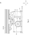
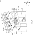
Figs. 7-8 illustrate partially enlarged views of a hanging device in accordance with some embodiments of the present invention. -
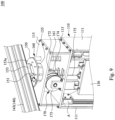
Fig. 9 illustrates a partially enlarged view of a hanging device, in which an accommodation main body of the hanging device rotates to an angle different from that of the hanging devices inFigs. 7-8 . -
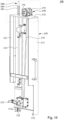
Fig. 10 illustrates a rear view of a hanging device in accordance with some embodiments of the present invention. -
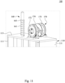
Fig. 11 illustrates a partially enlarged view according to the square S1 in theFig. 10 . -
Fig. 12 illustrates a rear view of a hanging device in accordance with some embodiments of the present invention, and a partial housing of a rotary handle is not shown. - Reference will now be made in detail to the present embodiments of the invention, examples of which are illustrated in the accompanying drawings. Wherever possible, the same reference numbers are used in the drawings and the description to refer to the same or like parts.
- Please refer to
Figs. 1-5 . In some embodiments of the present invention, ahanging device 100 includes an accommodationmain body 110, asliding assembly 120, and ahook 130. The accommodationmain body 110 includes twosidewalls 111 which are parallel arranged, in which a first vertical path is defined between the twosidewalls 111. The slidingassembly 120 is movably connected to the twosidewalls 111 such that the slidingassembly 120 moves relative to the accommodationmain body 110 along the first vertical path. In addition, thesliding assembly 120 further includes a slidingrail 121 which defines a second vertical path. Thehook 130 is movable connected to the slidingrail 121 such that thehook 130 can move relative to thesliding assembly 120 along the second vertical path. Therefore, thehook 130 is able to move relative to the accommodationmain body 110 along a vertical axis Z. A vertical moving length, relative to the accommodationmain body 110, of thehook 130 includes a length of the first vertical path and a length of the second vertical path, so thehook 130 has a quite long vertical moving length relative to the accommodationmain body 110. Accordingly, thehook 130 moves relative to the accommodationmain body 110 through the vertical moving length that is divided into two sections being the first vertical path and the second vertical path, thereby improving the structural strength of the hangingdevice 100 , so as to prevent thehook 130 from shaking when thehook 130 is vertically moving. - Specifically, the accommodation
main body 110, thesliding assembly 120, and thehook 130 can be made of metal such as alloy, polymer, or a composite material. The accommodationmain body 110, thesliding assembly 120, and thehook 130 can be made of aluminum alloy or steel, thereby improving the mechanical strength of the accommodationmain body 110, thesliding assembly 120, and thehook 130. The present invention is not limited in this respect. - In some embodiments of the present invention, the accommodation
main body 110 includes twoblock portions 112 which are respectively disposed at bottoms of the twosidewalls 111 such that the slidingassembly 120 moves downwardly relative to the accommodationmain body 110 along the vertical axis Z and can be stopped by theblock portions 112. Theblock portions 112 can prevent the slidingassembly 120 from falling outside of the first vertical path of the accommodationmain body 110. In addition, each of the twosidewalls 111 includes alinear guiding rail 111a extending along the vertical axis Z and being disposed on an interior surface of thecorresponding sidewall 111, and the slidingassembly 120 is slidably connected to thelinear guiding rail 111a such that the slidingassembly 120 can vertically move relative to the accommodationmain body 110 along thelinear guiding rails 111a. - In addition, the hanging
device 100 includes a damper A disposed between the slidingassembly 120 and one of thelinear guiding rails 111a, in which the damper A can prevent the slidingassembly 120 from moving too fast along the vertical axis Z and prevent the slidingassembly 120 from hitting theblock portions 112 of the accommodationmain body 110. Moreover, the accommodationmain body 110 includes a supportingboard 114 connected between the twosidewalls 111, in which the twosidewalls 111 and the supportingboard 114 collectively accommodate the slidingassembly 120 and thehook 130 such that the twosidewalls 111 and the supportingboard 114 protect the slidingassembly 120 and thehook 130 together. - In some embodiments of the present invention, the sliding
assembly 120 is substantially T-shaped, and the slidingassembly 120 has two wings respectively movably connected to the linear guiding rails 111a of the twosidewalls 111. Since the twosidewalls 111 collectively support the slidingassembly 120, the slidingassembly 120 can stably move relative to the accommodationmain body 110. The slidingassembly 120 barely shakes when the slidingassembly 120 is moving along the vertical axis Z. In addition, the slidingassembly 120 includes two slidingrails 121 vertically extend, in which the two slidingrail 121 are parallel to each other and disposed at a front side of the slidingassembly 120. Thehook 130 is movably connected to the two slidingrails 121 such that thehook 130 stably moves relative to the slidingassembly 120 along the vertical axis Z. Moreover, the slidingassembly 120 includes twoblock portions 122 respectively disposed at bottoms of the two slidingrails 121. Thehook 130 moves downwardly relative to the slidingassembly 120 along the vertical axis Z, and then thehook 130 stops by theblock portions 122 such that theblock portions 122 can prevent thehook 130 from falling out of the second vertical path. - In some embodiments of the present invention, the hanging
device 100 further includes atransportation assembly 140 configured to drive the accommodationmain body 110 to move along a horizontal direction which can be any horizontal direction within a plane defined by a first horizontal axis X and a second horizontal axis Y. Thetransportation assembly 140 includes atransportation rail 141 and atransportation rod 143, in which thetransportation rod 143 is movably connected to thetransportation rail 141 and configured to move relative to thetransportation rail 141 along the first horizontal axis X. In addition, the accommodationmain body 110 is movably connected to thetransportation rod 143 and configured to move relative to thetransportation rod 143 along the second horizontal axis Y, in which the first horizontal axis X is substantially perpendicular to the second horizontal axis Y, the present invention is not limited in this respect. - More specifically, the
transportation rail 141 includes twotransportation guiding rods 141a spaced apart and parallel to each other, and the twotransportation guiding rods 141a extend along the first horizontal axis X. Moreover, thetransportation rod 143 has two ends respectively movably connected to the twotransportation guiding rods 141a, and thetransportation rod 143 extends along the second horizontal axis Y. As such, thetransportation assembly 140 can drive the accommodationmain body 110 and thehook 130 to move along the first horizontal axis X and/ or the second horizontal axis Y such that the hangingdevice 100 can drive thehook 130 to freely move in three-dimensional (including X, Y and Z axes) space for grabbing objects. - Please refer to
Figs. 6-9 . In some embodiments of the present invention, the hangingdevice 100 further includes arotating assembly 150 and a fixingrod 160, in which the fixingrod 160 is disposed at the accommodationmain body 110, and the fixingrod 160 can be moved out or inserted into apositioning groove 151 of therotating assembly 150 such that therotating assembly 150 is in a rotatable state or a locking state. Specifically, the rotatingassembly 150 includes anupper portion 153 and a lower portion155, and theupper portion 153 is rotatably connected to thelower portion 155, thepositioning groove 151 is disposed at theupper portion 153 such that thepositioning groove 151 and theupper portion 153 can rotate relative to thelower portion 155. In addition, thepositioning groove 151 includes a plurality ofpositioning grooves 151, such as twopositioning grooves 151, fourpositioning grooves 151, sixpositioning grooves 151, and twelvepositioning grooves 151, which surround a rotation axis of therotating assembly 150. Thepositioning grooves 151 are disposed at an edge of abottom plate 153a of theupper portion 153 and evenly spaced apart from the rotation axis, and thebottom plate 153a which is substantially ring-shaped surrounds periphery sidewalls of theupper portion 153, thebottom plate 153a extends along the horizontal plane direction. More specifically, thetransportation rod 143 is fixed to theupper portion 153, and the accommodationmain body 110 is fixed to thelower portion 155 such that the accommodationmain body 110 and thehook 130 can rotate relative to thetransportation assembly 140 through therotating assembly 150. Therefore, thehook 130 of the hangingdevice 100 can rotate around the vertical axis Z, so as to freely grab an object to be hung. - In some embodiments of the present invention, the accommodation
main body 110 includes anupper board 113 extending along the horizontal plane direction, and theupper board 113 is connected between the twosidewalls 111. The fixingrod 160 includes anelastic portion 161 and a stoppingportion 163, and the fixingrod 160 extends through theupper board 113, theelastic portion 161 of the fixingrod 160 is disposed on theupper board 113. The stoppingportion 163 is disposed between thebottom plate 153a of theupper portion 153 and theupper board 113. Specifically, theelastic portion 161 can be a spring sleeved on the body of the fixingrod 160. In practice, users can pull out the fixingrod 160 from thepositioning groove 151 or insert the fixingrod 160 into thepositioning groove 151 along the vertical axis Z such that theelastic portion 161 can elastically deform or elastically recover. Referring toFigs. 8 and9 , the users can apply a downward pulling force along the vertical axis Z to the fixingrod 160, and the fixingrod 160 is moved outside of thepositioning groove 151 to make therotating assembly 150 in the rotatable state such that theupper board 113 of the accommodationmain body 110 and the stoppingportion 163 can collectively press theelastic portion 161. Referring toFig. 6 , when the users release the aforementioned downward pulling force to align the fixingrod 160 with thepositioning groove 151, theelastic portion 161 is elastically recovered to generate an elastic force pushing the fixingrod 160 to be inserted into thepositioning groove 151 such that therotating assembly 150 in in the locking state. - Please refer to
Figs. 4-6 and10-12 . In some embodiments of the present invention, the hangingdevice 100 further includes apulley assembly 170, and the accommodationmain body 110 further includes acap 115 disposed on theupper board 113. Thepulley assembly 170 is configured to drive thehook 130 to vertically move relative to the accommodationmain body 110. Thepulley assembly 170 includes arotary handle 171, afirst pulley 172, asecond pulley 173, adrive belt 174, and awire rope 175, and thefirst pulley 172 and thesecond pulley 173 are coaxially connected, thedrive belt 174 is fastened to thefirst pulley 172 and therotary handle 171. Thewire rope 175 is fastened between thesecond pulley 173 and thehook 130, and therotary handle 171 is configured to drive thesecond pulley 173 to rotate and drive thehook 130 to move relative to the accommodationmain body 110 along the vertical axis Z. - In detail, the
rotary handle 171 and thedrive belt 174 are disposed at a rear side of the supportingboard 114, and thehook 130 is disposed at a front side of the supportingboard 114. In addition, thefirst pulley 172 and thesecond pulley 173 are fixed pulleys located above theupper board 113, and thefirst pulley 172 and thesecond pulley 173 are above therotary handle 171. Thecap 115 accommodates thefirst pulley 172 and thesecond pulley 173, and thesecond pulley 173 is disposed directly above thehook 130 and at the front side of the supportingboard 114. Thefirst pulley 172 is disposed directly above therotary handle 171 and at the rear side of the supportingboard 114. In addition, therotary handle 171 further includes athird pulley 171a, and thedrive belt 174 is fastened to thefirst pulley 172 and thethird pulley 171a. As such, the users can easily rotate therotary handle 171 to drive thehook 130 to move relative to the accommodationmain body 110 through thedrive belt 174 along the vertical axis Z. In addition, therotary handle 171 is below thefirst pulley 172 and thesecond pulley 173, and thus the users can operate therotary handle 171 at a lower position, so as to drive thehook 130 to hang the object to be hung. - To sum up, in embodiments of the present invention, a hanging device capable of improving the degrees of freedom regarding movement and rotation of a hook is provided, and the hanging device is benefit for improving stability when the hanging device is lifting the object to be hung. The hanging device includes a vertical path in two sections through which the hook is stably lifted or lowered when grabbing the object to be hung. Moreover, the hanging device further includes a transportation assembly configured to move the hook along two horizontal axes perpendicular to each other. The hanging device further includes a rotating assembly which is configured to rotate the hook around the vertical axis relative to the transportation assembly. Therefore, the hook can not only freely move in three-dimensional directions but also rotate freely, and the hanging device of the present invention can use the hook to grab objects under a great degree of freedom, so as to decrease the blind spot about the hanging operation.
Claims (15)
- A hanging device (100), characterized by comprising:an accommodation main body (110) having two parallel sidewalls (111), wherein a first vertical path is defined between the two sidewalls (111);a sliding assembly (120) movably connected between the two sidewalls (111), and the sliding assembly (120) is configured to move relative to the accommodation main body (110) along the first vertical path, wherein the sliding assembly (120) further includes a sliding rail (121), the sliding rail (121) defines a second vertical path; anda hook (130) movably connected to the sliding rail (121), and the hook (130) is configured to move relative to the sliding assembly (120) along the second vertical path.
- The hanging device (100) of claim 1, further comprising a transportation assembly (140), wherein transportation assembly (140) is connected to the accommodation main body (110) and configured to drive the accommodation main body (110) to move along a horizontal direction.
- The hanging device (100) of claim 1, further characterized by comprising a transportation assembly (140), wherein the transportation assembly (140) includes a transportation rail (141) and a transportation rod (143), wherein the transportation rod (143) is movably connected to the transportation rail (141) and configured to move relative to the transportation rail (141) along a first horizontal axis (X), the accommodation main body (110) is movably connected to the transportation rod (143) and configured to move relative to the transportation rod (143) along a second horizontal axis (Y), wherein the first horizontal axis (X) is substantially perpendicular to the second horizontal axis (Y).
- The hanging device (100) of claim 2, further characterized by comprising a rotating assembly (150), wherein the rotating assembly (150) is connected between the accommodation main body (110) and the transportation assembly (140) such that the accommodation main body (110) rotates relative to the transportation assembly (140) around a vertical axis (Z).
- The hanging device (100) of claim 4, further characterized by comprising a fixing rod (160), wherein the fixing rod (160) is disposed on the accommodation main body (110), the fixing rod (160) is configured to move outside of at least one positioning groove (151) of the rotating assembly (150) such that the rotating assembly (150) is in a rotatable state, and the fixing rod (160) is configured to move into the at least one positioning groove (151) of the rotating assembly (150) such that the rotating assembly (150) is in a locking state.
- The hanging device (100) of claim 5, wherein the fixing rod (160) comprises an elastic portion (161) and a stopping portion (163), the fixing rod (160) is configured to move out from or move into the at least one positioning groove (151) such that the stopping portion (163) and the accommodation main body (110) collectively press the elastic portion (161) or collectively release the elastic portion (161).
- The hanging device (100) of claim 5, wherein the at least one positioning groove (151) includes a plurality of the positioning grooves (151), the positioning grooves (151) are arranged to surround a rotation axis of the rotating assembly (150).
- The hanging device (100) of claim 1, further characterized by comprising a pulley assembly (170) which is disposed on the accommodation main body (110) and configured to drive the hook (130) to move relative to the accommodation main body (110).
- The hanging device (100) of claim 1, further characterized by comprising a pulley assembly (170) which is disposed on the accommodation main body (110), wherein the pulley assembly (170) comprises a first pulley (172), a second pulley (173), a drive belt (174), and a rotary handle (171), wherein the first pulley (172) and the second pulley (173) are coaxially connected, the drive belt (174) is fastened to the first pulley (172) and the rotary handle (171), and wherein the rotary handle (171) is configured to drive the first pulley (172), so as to drive the hook (130) to vertically move relative to the accommodation main body (110).
- A hanging device (100), comprising:an accommodation main body (110) having two parallel sidewalls (111) which define a first vertical path between the two sidewalls (111);a sliding assembly (120) movably connected between the two sidewalls (111) and configured to move relative to the accommodation main body (110) along the first vertical path, wherein the sliding assembly (120) further includes a sliding rail (121) which defines a second vertical path;a hook (130) movably connected to the sliding rail (121) and configured to move relative to the sliding assembly (120) along the second vertical path; anda transportation assembly (140) connected to the accommodation main body (110) and configured to drive the accommodation main body (110) to move along a horizontal plane direction.
- The hanging device (100) of claim 10, further comprising a transportation assembly (140) which includes a transportation rail (141) and a transportation rod (143), wherein the transportation rod (143) is movably connected to the transportation rail (141) and configured to move relative to the transportation rail (141) along a first horizontal axis, the accommodation main body (110) is movably connected to the transportation rod (143) and configured to move relative to the transportation rod (143) along a second horizontal axis.
- The hanging device (100) of claim 10, further comprising a rotating assembly (150), wherein the accommodation main body (110) is connected between the accommodation main body (110) and the transportation assembly (140), such that the accommodation main body (110) rotates relative to the transportation assembly (140) around a vertical axis.
- The hanging device (100) of claim 12, further comprising a fixing rod (160) disposed on the accommodation main body (110), wherein the fixing rod (160) is configured to move outside of a positioning groove (151) of the rotating assembly (150) such that the rotating assembly (150) is in a rotatable state, and the fixing rod (160) is configured to move into the positioning groove (151) of the rotating assembly (150) such that the rotating assembly (150) is in a locking state.
- The hanging device (100) of claim 13, wherein the fixing rod (160) comprises an elastic portion (161) and a stopping portion (163), the fixing rod (160) is configured to move outside of the positioning groove (151) such that the stopping portion (163) and the accommodation main body (110) collectively press the elastic portion (161), and wherein the fixing rod (160) is configured to move into the positioning groove (151) such that the stopping portion (163) and the accommodation main body (110) collectively release the elastic portion (161).
- The hanging device (100) of claim 10, further comprising a pulley assembly (170) which is disposed on the accommodation main body (110) and configured to drive the hook (130) to move relative to the accommodation main body (110).
Applications Claiming Priority (2)
| Application Number | Priority Date | Filing Date | Title |
|---|---|---|---|
| US202163203870P | 2021-08-03 | 2021-08-03 | |
| CN202210001625.4A CN115872295B (en) | 2021-08-03 | 2022-01-04 | Hanging device |
Publications (3)
| Publication Number | Publication Date |
|---|---|
| EP4129120A1 true EP4129120A1 (en) | 2023-02-08 |
| EP4129120B1 EP4129120B1 (en) | 2024-07-31 |
| EP4129120C0 EP4129120C0 (en) | 2024-07-31 |
Family
ID=81326263
Family Applications (1)
| Application Number | Title | Priority Date | Filing Date |
|---|---|---|---|
| EP22166632.4A Active EP4129120B1 (en) | 2021-08-03 | 2022-04-05 | Hanging device |
Country Status (2)
| Country | Link |
|---|---|
| US (1) | US20230038997A1 (en) |
| EP (1) | EP4129120B1 (en) |
Cited By (1)
| Publication number | Priority date | Publication date | Assignee | Title |
|---|---|---|---|---|
| CN116140561A (en) * | 2023-03-27 | 2023-05-23 | 江苏众智合金钢有限公司 | Precision casting equipment for investment silica sol |
Families Citing this family (1)
| Publication number | Priority date | Publication date | Assignee | Title |
|---|---|---|---|---|
| CN116212269A (en) * | 2023-03-01 | 2023-06-06 | 金川集团股份有限公司 | Seat belt suspension device for loading and unloading vehicle |
Citations (3)
| Publication number | Priority date | Publication date | Assignee | Title |
|---|---|---|---|---|
| AT399306B (en) * | 1993-08-02 | 1995-04-25 | Ehrenleitner Franz | C-hook |
| WO2020201400A1 (en) * | 2019-04-05 | 2020-10-08 | Liebherr-Werk Biberach Gmbh | Building and/or material handling machine and method for guiding and moving a working head |
| CN212151304U (en) * | 2020-03-26 | 2020-12-15 | 山东水泊焊割设备制造有限公司 | Suspension grabbing and positioning tool |
Family Cites Families (5)
| Publication number | Priority date | Publication date | Assignee | Title |
|---|---|---|---|---|
| US6524054B2 (en) * | 2001-05-15 | 2003-02-25 | Finus Maney | Vehicular mounted lift |
| JP2009001406A (en) * | 2007-06-25 | 2009-01-08 | Ihi Corp | Stacker crane |
| JP5459558B2 (en) * | 2010-12-24 | 2014-04-02 | 株式会社ダイフク | Stacker crane |
| WO2014038300A1 (en) * | 2012-09-04 | 2014-03-13 | 村田機械株式会社 | Stacker crane |
| US9802801B2 (en) * | 2012-09-05 | 2017-10-31 | Murata Machinery, Ltd. | Stacker crane |
-
2022
- 2022-04-01 US US17/657,630 patent/US20230038997A1/en active Pending
- 2022-04-05 EP EP22166632.4A patent/EP4129120B1/en active Active
Patent Citations (3)
| Publication number | Priority date | Publication date | Assignee | Title |
|---|---|---|---|---|
| AT399306B (en) * | 1993-08-02 | 1995-04-25 | Ehrenleitner Franz | C-hook |
| WO2020201400A1 (en) * | 2019-04-05 | 2020-10-08 | Liebherr-Werk Biberach Gmbh | Building and/or material handling machine and method for guiding and moving a working head |
| CN212151304U (en) * | 2020-03-26 | 2020-12-15 | 山东水泊焊割设备制造有限公司 | Suspension grabbing and positioning tool |
Cited By (2)
| Publication number | Priority date | Publication date | Assignee | Title |
|---|---|---|---|---|
| CN116140561A (en) * | 2023-03-27 | 2023-05-23 | 江苏众智合金钢有限公司 | Precision casting equipment for investment silica sol |
| CN116140561B (en) * | 2023-03-27 | 2024-01-12 | 江苏众智合金钢有限公司 | Precision casting equipment for investment silica sol |
Also Published As
| Publication number | Publication date |
|---|---|
| EP4129120B1 (en) | 2024-07-31 |
| US20230038997A1 (en) | 2023-02-09 |
| EP4129120C0 (en) | 2024-07-31 |
Similar Documents
| Publication | Publication Date | Title |
|---|---|---|
| EP4129120B1 (en) | Hanging device | |
| CN105347167B (en) | A permanent magnetic adsorption metal hoisting machine | |
| JPWO2014038300A1 (en) | Stacker crane | |
| JP2017149565A (en) | Winding-up device | |
| US20150367507A1 (en) | Remotely Operated Manipulator | |
| KR101715302B1 (en) | Latching devices for hoist crane | |
| CN203765384U (en) | Rotary table structure of machine tool | |
| KR101404636B1 (en) | The material transported gantry rotation gripper device of two sides support type to vertical up-down gripper unit | |
| CN119528003A (en) | A heavy lifting equipment for lifting and moving | |
| TWI800202B (en) | Hanging device | |
| CN111115515B (en) | Unmanned forklift | |
| KR102260492B1 (en) | Clamping apparatus for fork lift | |
| CN109264381A (en) | A kind of liftable chucking device of hold assembly | |
| KR102398081B1 (en) | Table lifter | |
| JP2014034431A (en) | Pit ladder apparatus | |
| KR101433096B1 (en) | The vertical up-down compensation horizontal-transfer device structure dedicating to material transported Gantry unit to be Using of up-down rotation-arm | |
| JP6796523B2 (en) | Loading material installation equipment | |
| CN115231292B (en) | Snatch turning device | |
| CN215825328U (en) | Novel sucking disc formula manipulator | |
| JP6336225B2 (en) | Elevator equipment | |
| CN212110529U (en) | Drop test machine | |
| CN217076192U (en) | Gripping tool and automatic loading and unloading all-in-one machine | |
| KR20200007552A (en) | Permanent magnet fixed type conveying device | |
| JPH085935Y2 (en) | Slack removal structure for hanging steel rope members of heavy load lifting device and heavy load carrier using the structure | |
| CN218859734U (en) | Heavy-duty manipulator clamping and supporting mechanism |
Legal Events
| Date | Code | Title | Description |
|---|---|---|---|
| PUAI | Public reference made under article 153(3) epc to a published international application that has entered the european phase |
Free format text: ORIGINAL CODE: 0009012 |
|
| STAA | Information on the status of an ep patent application or granted ep patent |
Free format text: STATUS: THE APPLICATION HAS BEEN PUBLISHED |
|
| STAA | Information on the status of an ep patent application or granted ep patent |
Free format text: STATUS: REQUEST FOR EXAMINATION WAS MADE |
|
| AK | Designated contracting states |
Kind code of ref document: A1 Designated state(s): AL AT BE BG CH CY CZ DE DK EE ES FI FR GB GR HR HU IE IS IT LI LT LU LV MC MK MT NL NO PL PT RO RS SE SI SK SM TR |
|
| 17P | Request for examination filed |
Effective date: 20230130 |
|
| RBV | Designated contracting states (corrected) |
Designated state(s): AL AT BE BG CH CY CZ DE DK EE ES FI FR GB GR HR HU IE IS IT LI LT LU LV MC MK MT NL NO PL PT RO RS SE SI SK SM TR |
|
| GRAP | Despatch of communication of intention to grant a patent |
Free format text: ORIGINAL CODE: EPIDOSNIGR1 |
|
| STAA | Information on the status of an ep patent application or granted ep patent |
Free format text: STATUS: GRANT OF PATENT IS INTENDED |
|
| INTG | Intention to grant announced |
Effective date: 20240326 |
|
| GRAS | Grant fee paid |
Free format text: ORIGINAL CODE: EPIDOSNIGR3 |
|
| GRAA | (expected) grant |
Free format text: ORIGINAL CODE: 0009210 |
|
| STAA | Information on the status of an ep patent application or granted ep patent |
Free format text: STATUS: THE PATENT HAS BEEN GRANTED |
|
| AK | Designated contracting states |
Kind code of ref document: B1 Designated state(s): AL AT BE BG CH CY CZ DE DK EE ES FI FR GB GR HR HU IE IS IT LI LT LU LV MC MK MT NL NO PL PT RO RS SE SI SK SM TR |
|
| REG | Reference to a national code |
Ref country code: CH Ref legal event code: EP Ref country code: GB Ref legal event code: FG4D |
|
| REG | Reference to a national code |
Ref country code: DE Ref legal event code: R096 Ref document number: 602022004886 Country of ref document: DE |
|
| REG | Reference to a national code |
Ref country code: IE Ref legal event code: FG4D |
|
| U01 | Request for unitary effect filed |
Effective date: 20240826 |
|
| U07 | Unitary effect registered |
Designated state(s): AT BE BG DE DK EE FI FR IT LT LU LV MT NL PT RO SE SI Effective date: 20240904 |
|
| PG25 | Lapsed in a contracting state [announced via postgrant information from national office to epo] |
Ref country code: NO Free format text: LAPSE BECAUSE OF FAILURE TO SUBMIT A TRANSLATION OF THE DESCRIPTION OR TO PAY THE FEE WITHIN THE PRESCRIBED TIME-LIMIT Effective date: 20241031 |
|
| PG25 | Lapsed in a contracting state [announced via postgrant information from national office to epo] |
Ref country code: GR Free format text: LAPSE BECAUSE OF FAILURE TO SUBMIT A TRANSLATION OF THE DESCRIPTION OR TO PAY THE FEE WITHIN THE PRESCRIBED TIME-LIMIT Effective date: 20241101 Ref country code: PL Free format text: LAPSE BECAUSE OF FAILURE TO SUBMIT A TRANSLATION OF THE DESCRIPTION OR TO PAY THE FEE WITHIN THE PRESCRIBED TIME-LIMIT Effective date: 20240731 |
|
| PG25 | Lapsed in a contracting state [announced via postgrant information from national office to epo] |
Ref country code: IS Free format text: LAPSE BECAUSE OF FAILURE TO SUBMIT A TRANSLATION OF THE DESCRIPTION OR TO PAY THE FEE WITHIN THE PRESCRIBED TIME-LIMIT Effective date: 20241130 |
|
| PG25 | Lapsed in a contracting state [announced via postgrant information from national office to epo] |
Ref country code: HR Free format text: LAPSE BECAUSE OF FAILURE TO SUBMIT A TRANSLATION OF THE DESCRIPTION OR TO PAY THE FEE WITHIN THE PRESCRIBED TIME-LIMIT Effective date: 20240731 |
|
| PG25 | Lapsed in a contracting state [announced via postgrant information from national office to epo] |
Ref country code: ES Free format text: LAPSE BECAUSE OF FAILURE TO SUBMIT A TRANSLATION OF THE DESCRIPTION OR TO PAY THE FEE WITHIN THE PRESCRIBED TIME-LIMIT Effective date: 20240731 Ref country code: RS Free format text: LAPSE BECAUSE OF FAILURE TO SUBMIT A TRANSLATION OF THE DESCRIPTION OR TO PAY THE FEE WITHIN THE PRESCRIBED TIME-LIMIT Effective date: 20241031 |
|
| PG25 | Lapsed in a contracting state [announced via postgrant information from national office to epo] |
Ref country code: RS Free format text: LAPSE BECAUSE OF FAILURE TO SUBMIT A TRANSLATION OF THE DESCRIPTION OR TO PAY THE FEE WITHIN THE PRESCRIBED TIME-LIMIT Effective date: 20241031 Ref country code: PL Free format text: LAPSE BECAUSE OF FAILURE TO SUBMIT A TRANSLATION OF THE DESCRIPTION OR TO PAY THE FEE WITHIN THE PRESCRIBED TIME-LIMIT Effective date: 20240731 Ref country code: NO Free format text: LAPSE BECAUSE OF FAILURE TO SUBMIT A TRANSLATION OF THE DESCRIPTION OR TO PAY THE FEE WITHIN THE PRESCRIBED TIME-LIMIT Effective date: 20241031 Ref country code: IS Free format text: LAPSE BECAUSE OF FAILURE TO SUBMIT A TRANSLATION OF THE DESCRIPTION OR TO PAY THE FEE WITHIN THE PRESCRIBED TIME-LIMIT Effective date: 20241130 Ref country code: HR Free format text: LAPSE BECAUSE OF FAILURE TO SUBMIT A TRANSLATION OF THE DESCRIPTION OR TO PAY THE FEE WITHIN THE PRESCRIBED TIME-LIMIT Effective date: 20240731 Ref country code: GR Free format text: LAPSE BECAUSE OF FAILURE TO SUBMIT A TRANSLATION OF THE DESCRIPTION OR TO PAY THE FEE WITHIN THE PRESCRIBED TIME-LIMIT Effective date: 20241101 Ref country code: ES Free format text: LAPSE BECAUSE OF FAILURE TO SUBMIT A TRANSLATION OF THE DESCRIPTION OR TO PAY THE FEE WITHIN THE PRESCRIBED TIME-LIMIT Effective date: 20240731 |
|
| PG25 | Lapsed in a contracting state [announced via postgrant information from national office to epo] |
Ref country code: SM Free format text: LAPSE BECAUSE OF FAILURE TO SUBMIT A TRANSLATION OF THE DESCRIPTION OR TO PAY THE FEE WITHIN THE PRESCRIBED TIME-LIMIT Effective date: 20240731 |
|
| U20 | Renewal fee for the european patent with unitary effect paid |
Year of fee payment: 4 Effective date: 20250310 |
|
| PG25 | Lapsed in a contracting state [announced via postgrant information from national office to epo] |
Ref country code: CZ Free format text: LAPSE BECAUSE OF FAILURE TO SUBMIT A TRANSLATION OF THE DESCRIPTION OR TO PAY THE FEE WITHIN THE PRESCRIBED TIME-LIMIT Effective date: 20240731 |
|
| PG25 | Lapsed in a contracting state [announced via postgrant information from national office to epo] |
Ref country code: SK Free format text: LAPSE BECAUSE OF FAILURE TO SUBMIT A TRANSLATION OF THE DESCRIPTION OR TO PAY THE FEE WITHIN THE PRESCRIBED TIME-LIMIT Effective date: 20240731 |
|
| PLBE | No opposition filed within time limit |
Free format text: ORIGINAL CODE: 0009261 |
|
| STAA | Information on the status of an ep patent application or granted ep patent |
Free format text: STATUS: NO OPPOSITION FILED WITHIN TIME LIMIT |
|
| 26N | No opposition filed |
Effective date: 20250501 |
|
| REG | Reference to a national code |
Ref country code: CH Ref legal event code: H13 Free format text: ST27 STATUS EVENT CODE: U-0-0-H10-H13 (AS PROVIDED BY THE NATIONAL OFFICE) Effective date: 20251125 |
|
| PG25 | Lapsed in a contracting state [announced via postgrant information from national office to epo] |
Ref country code: MC Free format text: LAPSE BECAUSE OF FAILURE TO SUBMIT A TRANSLATION OF THE DESCRIPTION OR TO PAY THE FEE WITHIN THE PRESCRIBED TIME-LIMIT Effective date: 20240731 |
|
| PG25 | Lapsed in a contracting state [announced via postgrant information from national office to epo] |
Ref country code: CH Free format text: LAPSE BECAUSE OF NON-PAYMENT OF DUE FEES Effective date: 20250430 |
|
| PGFP | Annual fee paid to national office [announced via postgrant information from national office to epo] |
Ref country code: GB Payment date: 20260313 Year of fee payment: 5 |
|
| PG25 | Lapsed in a contracting state [announced via postgrant information from national office to epo] |
Ref country code: IE Free format text: LAPSE BECAUSE OF NON-PAYMENT OF DUE FEES Effective date: 20250405 |
|
| U20 | Renewal fee for the european patent with unitary effect paid |
Year of fee payment: 5 Effective date: 20260310 |