EP4128915B1 - Meldung der integrität einer netzwerkunterstützungspositionierung - Google Patents
Meldung der integrität einer netzwerkunterstützungspositionierung Download PDFInfo
- Publication number
- EP4128915B1 EP4128915B1 EP21718207.0A EP21718207A EP4128915B1 EP 4128915 B1 EP4128915 B1 EP 4128915B1 EP 21718207 A EP21718207 A EP 21718207A EP 4128915 B1 EP4128915 B1 EP 4128915B1
- Authority
- EP
- European Patent Office
- Prior art keywords
- parameter
- wireless device
- positioning
- network node
- information
- Prior art date
- Legal status (The legal status is an assumption and is not a legal conclusion. Google has not performed a legal analysis and makes no representation as to the accuracy of the status listed.)
- Active
Links
Images


Classifications
-
- H—ELECTRICITY
- H04—ELECTRIC COMMUNICATION TECHNIQUE
- H04W—WIRELESS COMMUNICATION NETWORKS
- H04W64/00—Locating users or terminals or network equipment for network management purposes, e.g. mobility management
-
- G—PHYSICS
- G01—MEASURING; TESTING
- G01S—RADIO DIRECTION-FINDING; RADIO NAVIGATION; DETERMINING DISTANCE OR VELOCITY BY USE OF RADIO WAVES; LOCATING OR PRESENCE-DETECTING BY USE OF THE REFLECTION OR RERADIATION OF RADIO WAVES; ANALOGOUS ARRANGEMENTS USING OTHER WAVES
- G01S5/00—Position-fixing by co-ordinating two or more direction or position line determinations; Position-fixing by co-ordinating two or more distance determinations
- G01S5/0009—Transmission of position information to remote stations
-
- G—PHYSICS
- G01—MEASURING; TESTING
- G01S—RADIO DIRECTION-FINDING; RADIO NAVIGATION; DETERMINING DISTANCE OR VELOCITY BY USE OF RADIO WAVES; LOCATING OR PRESENCE-DETECTING BY USE OF THE REFLECTION OR RERADIATION OF RADIO WAVES; ANALOGOUS ARRANGEMENTS USING OTHER WAVES
- G01S5/00—Position-fixing by co-ordinating two or more direction or position line determinations; Position-fixing by co-ordinating two or more distance determinations
- G01S5/02—Position-fixing by co-ordinating two or more direction or position line determinations; Position-fixing by co-ordinating two or more distance determinations using radio waves
- G01S5/0205—Details
- G01S5/0236—Assistance data, e.g. base station almanac
-
- G—PHYSICS
- G01—MEASURING; TESTING
- G01S—RADIO DIRECTION-FINDING; RADIO NAVIGATION; DETERMINING DISTANCE OR VELOCITY BY USE OF RADIO WAVES; LOCATING OR PRESENCE-DETECTING BY USE OF THE REFLECTION OR RERADIATION OF RADIO WAVES; ANALOGOUS ARRANGEMENTS USING OTHER WAVES
- G01S5/00—Position-fixing by co-ordinating two or more direction or position line determinations; Position-fixing by co-ordinating two or more distance determinations
- G01S5/02—Position-fixing by co-ordinating two or more direction or position line determinations; Position-fixing by co-ordinating two or more distance determinations using radio waves
- G01S5/0205—Details
- G01S5/0244—Accuracy or reliability of position solution or of measurements contributing thereto
-
- H—ELECTRICITY
- H04—ELECTRIC COMMUNICATION TECHNIQUE
- H04W—WIRELESS COMMUNICATION NETWORKS
- H04W12/00—Security arrangements; Authentication; Protecting privacy or anonymity
- H04W12/10—Integrity
- H04W12/108—Source integrity
-
- H—ELECTRICITY
- H04—ELECTRIC COMMUNICATION TECHNIQUE
- H04W—WIRELESS COMMUNICATION NETWORKS
- H04W4/00—Services specially adapted for wireless communication networks; Facilities therefor
- H04W4/02—Services making use of location information
- H04W4/029—Location-based management or tracking services
-
- H—ELECTRICITY
- H04—ELECTRIC COMMUNICATION TECHNIQUE
- H04W—WIRELESS COMMUNICATION NETWORKS
- H04W88/00—Devices specially adapted for wireless communication networks, e.g. terminals, base stations or access point devices
- H04W88/02—Terminal devices
-
- H—ELECTRICITY
- H04—ELECTRIC COMMUNICATION TECHNIQUE
- H04W—WIRELESS COMMUNICATION NETWORKS
- H04W88/00—Devices specially adapted for wireless communication networks, e.g. terminals, base stations or access point devices
- H04W88/08—Access point devices
-
- H—ELECTRICITY
- H04—ELECTRIC COMMUNICATION TECHNIQUE
- H04W—WIRELESS COMMUNICATION NETWORKS
- H04W88/00—Devices specially adapted for wireless communication networks, e.g. terminals, base stations or access point devices
- H04W88/18—Service support devices; Network management devices
Definitions
- the present disclosure generally relates to wireless communications and wireless communication networks.
- Standardization bodies such as Third Generation Partnership Project (3GPP) are studying potential solutions for efficient operation of wireless communication in new radio (NR) networks.
- the next generation mobile wireless communication system 5G/NR will support a diverse set of use cases and a diverse set of deployment scenarios. The later includes deployment at both low frequencies (e.g. 100s of MHz), similar to LTE today, and very high frequencies (e.g. mm waves in the tens of GHz).
- NR is being developed to also support machine type communication (MTC), ultra-low latency critical communications (URLCC), side-link device-to-device (D2D) and other use cases.
- MTC machine type communication
- URLCC ultra-low latency critical communications
- D2D side-link device-to-device
- LMF 130A represents the location management function entity in NR.
- LMF 130A represents the location management function entity in NR.
- the interactions between the gNodeB 120 and the device (UE) 110 are supported via the Radio Resource Control (RRC) protocol.
- RRC Radio Resource Control
- Other network nodes such as Access and Mobility Management Function (AMF) 130B and evolved Serving Mobile Location Center (e-SMLC) 130C, may be involved in positioning support.
- AMF Access and Mobility Management Function
- e-SMLC evolved Serving Mobile Location Center
- the gNB 120B and ng-eNB 120A may not always both be present.
- the NR positioning for Release 16 is positioned to provide added value in terms of enhanced location capabilities.
- the operation in low and high frequency bands (i.e. below and above 6GHz) and utilization of massive antenna arrays provide additional degrees of freedom to substantially improve the positioning accuracy.
- the possibility to use wide signal bandwidth in low and especially in high bands brings new performance bounds for user location for well-known positioning techniques based on OTDOA, U-TDOA, DL-TDOA, Cell-ID or E-Cell-ID etc., utilizing timing measurements to locate a UE.
- 3GPP TS 22.261 The 5G service requirements specified in 3GPP TS 22.261 include the need to determine the reliability, and the uncertainty or confidence level, of the position-related data.
- Integrity is referred to as the measure of trust that can be placed in the correctness of information supplied by a navigation system. Integrity includes the ability of a system to provide timely warnings to user receivers in case of failure. Any use case related to positioning in Ultra Reliable Low Latency Communication (URLLC) typically requires high integrity performance.
- Example use cases include V2X, autonomous driving, UAV (drones), eHealth, rail and maritime, emergency and mission critical. In use cases in which large errors can lead to serious consequences such as wrong legal decisions or wrong charge computation, etc., the integrity reporting may become crucial.
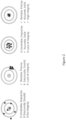
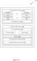
- Figure 2 illustrates an example definition of accuracy, precision, validity, reliability and integrity. It can be assumed that "accuracy” is the same term as “validity” in positioning. Also, terms such as reliability, precision, certainty and confidence level can be used interchangeably. However, integrity requires the evaluation of both accuracy and reliability.
- Alert Limit is the largest error allowable for safe operation.
- Time to Alert is the maximum allowable elapsed time from the onset of a positioning failure until the equipment announces the alert.
- Integrity Risk is the maximum probability of providing a signal that is out of tolerance without warning the user in a given period of time.
- Protection Level is the statistical error bound computed to guarantee that the probability of the absolute position error exceeding the said number is smaller than or equal to the target integrity risk.
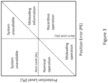
- Figure 3 illustrates an example Stanford plot in which the possible integrity operations and events can be explained in its different regions.
- Nominal Operation is when the Position Error (PE) is less than the Protection Level (PL) which is less than the Alert Limit (AL) (e.g. PE ⁇ PL ⁇ AL).
- PE Position Error
- PL Protection Level
- AL Alert Limit
- Integrity Failure is an integrity event that lasts for longer than the TTA and with no alarm raised within the TTA.
- MI Misleading Information
- HMI Hazardously Misleading Information
- Document US 2017/272900 A1 discloses a mobile device that generates position data for a device, receives a first access point position reliability state associated with the first access point, determines a reliability of the position data based on the first access point position reliability state and an estimated location of the first access point, determines a threshold reliability requirement of an application associated with the mobile device, compares the reliability of the position data to the threshold reliability requirement of the application, and provides the position data of the device based on the comparison.
- a network entity determines access point characteristics associated with an access point, generates a position reliability state for the access point, sends the position reliability state to a mobile device, receives position data associated with the mobile device, and determines a trustworthiness of the position data.
- NR Positioning in Rel-17 should evaluate and specify enhancements and solutions to meet the following exemplary performance targets: (a) For general commercial use cases (e.g., TS 22.261): sub-meter level position accuracy ( ⁇ 1 m), and (b) For IIoT Use Cases (e.g., 22.804): position accuracy ⁇ 0.2 m.
- the target latency requirement is ⁇ 100 ms; for some IIoT use cases, latency in the order of 10 ms is desired.
- Document EP 4 109 958 A1 constitutes prior art under Article 54(3) EPC and may be construed to disclose a method, an apparatus and a device for location service processing, and a medium.
- the method includes: after receiving a location service request, the location management function sending a QoS index requirement containing integrity to a terminal through a positioning protocol; the terminal performing auxiliary measurement function and integrity auxiliary monitoring according to the index requirement, and returning a measurement value to the location management function; and the location management function performing location estimation and integrity estimation according to the returned measurement value.
- a method performed by a network node comprises determining an integrity risk, IR, parameter associated with a wireless device, the IR parameter indicating a maximum probability of providing a positioning service that is out of a tolerance range; transmitting, to the wireless device, positioning assistance information and the IR parameter; and receiving, from the wireless device, an estimated position and a protection level, PL, parameter, the PL parameter indicating a statistical error bound computed to guarantee that probability of a position error exceeding the PL is less than or equal to the IR, wherein the method further comprises determining an integrity of the positioning estimation in accordance with the received PL parameter; or the IR parameter is associated with one or more positioning reference signal, PRS; or the IR parameter is determined in accordance with at least one of: a clock drift of the network node; a synchronization error of the network node; a wireless device type; a bandwidth and carrier frequency; an indoor or outdoor classification of the wireless device; a serving cell or serving beam;
- a method performed by a network node comprises determining an integrity risk, IR, parameter associated with a wireless device, the IR parameter indicating a maximum probability of providing a positioning service that is out of a tolerance range; transmitting, to the wireless device, positioning assistance information and the IR parameter; and receiving, from the wireless device, an estimated position and a protection level, PL, parameter, the PL parameter indicating a statistical error bound computed to guarantee that probability of a position error exceeding the PL is less than or equal to the IR, wherein the positioning assistance information is one of Observed Time Difference of Arrival, OTDOA, information or Downlink Time Difference of Arrival, DL-TDOA, information.
- a method performed by a network node comprises determining an integrity risk, IR, parameter associated with a wireless device, the IR parameter indicating a maximum probability of providing a positioning service that is out of a tolerance range; transmitting, to the wireless device, positioning assistance information and the IR parameter; and receiving, from the wireless device, an estimated position and a protection level, PL, parameter, the PL parameter indicating a statistical error bound computed to guarantee that probability of a position error exceeding the PL is less than or equal to the IR, further comprising: determining an alert limit, AL, parameter associated with the wireless device, the AL parameter indicating a largest error allowable for safe operation; and transmitting the AL parameter to the wireless device.
- a computer-readable medium comprising code portions which, when executed on a processor, configure the processor to perform the method according to any one of the first to third aspects.
- a network node comprising a radio interface and processing circuitry configured to perform the method according to any one of the first to third aspects.
- a method performed by a wireless device comprises receiving, from a network node, positioning assistance information and an integrity risk, IR, parameter, the IR parameter indicating a maximum probability of providing a positioning service that is out of a tolerance range; performing positioning measurements to determine an estimated position of the wireless device; determining a Protection Level, PL, parameter based at least in part on the IR parameter, the PL parameter indicating a statistical error bound computed to guarantee that probability of a position error exceeding the PL is less than or equal to the IR; and transmitting, to the network node, the estimated position and the PL parameter, wherein the method further comprises monitoring (204) the IR parameter while performing the positioning measurements; or the IR parameter is associated with one or more positioning reference signal, PRS; or the method further comprises monitoring (204) the IR parameter associated with each PRS to determine which PRS to include in positioning measurements; or the method further comprises receiving an alert limit, AL, parameter, the AL parameter indicating a largest error allowable
- a method performed by a wireless device comprises receiving, from a network node, positioning assistance information and an integrity risk, IR, parameter, the IR parameter indicating a maximum probability of providing a positioning service that is out of a tolerance range; performing positioning measurements to determine an estimated position of the wireless device; determining a Protection Level, PL, parameter based at least in part on the IR parameter, the PL parameter indicating a statistical error bound computed to guarantee that probability of a position error exceeding the PL is less than or equal to the IR; and transmitting, to the network node, the estimated position and the PL parameter, wherein the positioning assistance information is one of Observed Time Difference of Arrival, OTDOA, information or Downlink Time Difference of Arrival, DL-TDOA, information, wherein, optionally, the IR parameter is associated with a complete set of OTDOA or DL-TDOA information.
- IR integrity risk
- a computer-readable medium comprising code portions which, when executed on a processor, configure the processor to perform the method according to the sixth or seventh aspect.
- a wireless device comprising a radio interface and processing circuitry configured to perform the method according to the sixth or seventh aspect.
- the non-limiting term "user equipment” is used and it can refer to any type of wireless device which can communicate with a network node and/or with another UE in a cellular or mobile or wireless communication system.
- UE user equipment
- Examples of UE are target device, device to device (D2D) UE, machine type UE or UE capable of machine to machine (M2M) communication, personal digital assistant, tablet, mobile terminal, smart phone, laptop embedded equipped (LEE), laptop mounted equipment (LME), USB dongles, ProSe UE, V2V UE, V2X UE, MTC UE, eMTC UE, FeMTC UE, UE Cat 0, UE Cat M1, narrow band IoT (NB-IoT) UE, UE Cat NB1, etc.
- Example embodiments of a UE are described in more detail below with respect to Figure 9 .
- network node can correspond to any type of radio access node (or radio network node) or any network node, which can communicate with a UE and/or with another network node in a cellular or mobile or wireless communication system.
- Examples of network nodes are NodeB, MeNB, SeNB, a network node belonging to MCG or SCG, base station (BS), multi-standard radio (MSR) radio access node such as MSR BS, eNodeB, network controller, radio network controller (RNC), base station controller (BSC), relay, donor node controlling relay, base transceiver station (BTS), access point (AP), transmission points, transmission nodes, RRU, RRH, nodes in distributed antenna system (DAS), core network node (e.g. MSC, MME, etc.), O&M, OSS, Self-organizing Network (SON), positioning node (e.g. E-SMLC), MDT, test equipment, etc.
- MSR multi-standard radio
- the term "radio access technology” refers to any RAT e.g. UTRA, E-UTRA, narrow band internet of things (NB-IoT), WiFi, Bluetooth, next generation RAT (NR), 4G, 5G, etc. Any of the first and the second nodes may be capable of supporting a single or multiple RATs.
- radio node used herein can be used to denote a wireless device or a network node.
- a UE can be configured to operate in carrier aggregation (CA) implying aggregation of two or more carriers in at least one of downlink (DL) and uplink (UL) directions.
- CA carrier aggregation
- a UE can have multiple serving cells, wherein the term 'serving' herein means that the UE is configured with the corresponding serving cell and may receive from and/or transmit data to the network node on the serving cell e.g. on PCell or any of the SCells.
- the data is transmitted or received via physical channels e.g. PDSCH in DL, PUSCH in UL, etc.
- a component carrier also interchangeably called as carrier or aggregated carrier, PCC or SCC is configured at the UE by the network node using higher layer signaling e.g. by sending RRC configuration message to the UE.
- the configured CC is used by the network node for serving the UE on the serving cell (e.g. on PCell, PSCell, SCell, etc.) of the configured CC.
- the configured CC is also used by the UE for performing one or more radio measurements (e.g. RSRP, RSRQ, etc.) on the cells operating on the CC, e.g. PCell, SCell or PSCell and neighboring cells.
- a UE can also operate in dual connectivity (DC) or multi-connectivity (MC).
- the multicarrier or multicarrier operation can be any of CA, DC, MC, etc.
- the term "multicarrier" can also be interchangeably called a band combination.
- Radio measurement used herein may refer to any measurement performed on radio signals. Radio measurements can be absolute or relative. Radio measurements can be e.g. intra-frequency, inter-frequency, CA, etc. Radio measurements can be unidirectional (e.g., DL or UL or in either direction on a sidelink) or bidirectional (e.g., RTT, Rx-Tx, etc.).
- radio measurements include timing measurements (e.g., propagation delay, TOA, timing advance, RTT, RSTD, Rx-Tx, etc.), angle measurements (e.g., angle of arrival), power-based or channel quality measurements (e.g., path loss, received signal power, RSRP, received signal quality, RSRQ, SINR, SNR, interference power, total interference plus noise, RSSI, noise power, CSI, CQI, PMI, etc.), cell detection or cell identification, RLM, SI reading, etc.
- the measurement may be performed on one or more links in each direction, e.g., RSTD or relative RSRP or based on signals from different transmission points of the same (shared) cell.
- signaling used herein may comprise any of high-layer signaling (e.g., via RRC or a like), lower-layer signaling (e.g., via a physical control channel or a broadcast channel), or a combination thereof.
- the signaling may be implicit or explicit.
- the signaling may further be unicast, multicast or broadcast.
- the signaling may also be directly to another node or via a third node.
- time resource used herein may correspond to any type of physical resource or radio resource expressed in terms of length of time. Examples of time resources include symbol, time slot, sub-frame, radio frame, TTI, interleaving time, etc.
- frequency resource may refer to sub-band within a channel bandwidth, subcarrier, carrier frequency, frequency band.
- time and frequency resources may refer to any combination of time and frequency resources.
- UE operation include: UE radio measurement (see the term "radio measurement” above), bidirectional measurement with UE transmitting, cell detection or identification, beam detection or identification, system information reading, channel receiving and decoding, any UE operation or activity involving at least receiving of one or more radio signals and/or channels, cell change or (re)selection, beam change or (re)selection, a mobility-related operation, a measurement-related operation, a radio resource management (RRM)-related operation, a positioning procedure, a timing related procedure, a timing adjustment related procedure, UE location tracking procedure, time tracking related procedure, synchronization related procedure, MDT-like procedure, measurement collection related procedure, a CA-related procedure, serving cell activation/deactivation, CC configuration/de-configuration, etc.
- RRM radio resource management
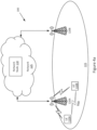
- FIG. 4a illustrates an example of a wireless network 100 that can be used for wireless communications.
- Wireless network 100 includes wireless devices, such as UEs 110A-110B, and network nodes, such as radio access nodes 120A-120B (e.g. eNBs, gNBs, etc.), connected to one or more core network nodes 130 via an interconnecting network 125.
- the network 100 can use any suitable deployment scenarios.
- UEs 110 within coverage area 115 can each be capable of communicating directly with radio access nodes 120 over a wireless interface.
- UEs 110 can also be capable of communicating with each other via D2D communication.
- UE 110A can communicate with radio access node 120A over a wireless interface. That is, UE 110A can transmit wireless signals to and/or receive wireless signals from radio access node 120A.
- the wireless signals can contain voice traffic, data traffic, control signals, and/or any other suitable information.
- an area of wireless signal coverage 115 associated with a radio access node 120 can be referred to as a cell.
- the interconnecting network 125 can refer to any interconnecting system capable of transmitting audio, video, signals, data, messages, etc., or any combination of the preceding.
- the interconnecting network 125 can include all or a portion of a public switched telephone network (PSTN), a public or private data network, a local area network (LAN), a metropolitan area network (MAN), a wide area network (WAN), a local, regional, or global communication or computer network such as the Internet, a wireline or wireless network, an enterprise intranet, or any other suitable communication link, including combinations thereof.
- PSTN public switched telephone network
- LAN local area network
- MAN metropolitan area network
- WAN wide area network
- Internet a local, regional, or global communication or computer network
- wireline or wireless network an enterprise intranet, or any other suitable communication link, including combinations thereof.
- the network node 130 can be a core network node 130, managing the establishment of communication sessions and other various other functionalities for UEs 110.
- core network node 130 can include mobile switching center (MSC), MME, serving gateway (SGW), packet data network gateway (PGW), operation and maintenance (O&M), operations support system (OSS), SON, positioning node (e.g., Enhanced Serving Mobile Location Center, E-SMLC), location server node, MDT node, etc.
- UEs 110 can exchange certain signals with the core network node using the non-access stratum layer. In non-access stratum signaling, signals between UEs 110 and the core network node 130 can be transparently passed through the radio access network.
- radio access nodes 120 can interface with one or more network nodes 130 over an internode interface.
- radio access node 120 can be a "distributed" radio access node in the sense that the radio access node 120 components, and their associated functions, can be separated into two main units (or sub-radio network nodes) which can be referred to as the central unit (CU) and the distributed unit (DU).
- CU central unit
- DU distributed unit
- Different distributed radio network node architectures are possible.
- a DU can be connected to a CU via dedicated wired or wireless link (e.g., an optical fiber cable) while in other architectures, a DU can be connected a CU via a transport network.
- how the various functions of the radio access node 120 are separated between the CU(s) and DU(s) may vary depending on the chosen architecture.
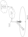
- Figure 4b illustrates an example of signaling in wireless network 100.
- the radio interface generally enables the UE 110 and the radio access node 120 to exchange signals and messages in both a downlink direction (from the radio access node 120 to the UE 110) and in an uplink direction (from the UE 110 to the radio access node 120).
- the radio interface between the wireless device 110 and the radio access node 120 typically enables the UE 110 to access various applications or services provided by one or more servers 140 (also referred to as application server or host computer) located in an external network(s) 135.
- the connectivity between the UE 110 and the server 140 enabled at least in part by the radio interface between the UE 110 and the radio access node 120, can be described as an "over-the-top” (OTT) or "application layer” connection.
- OTT over-the-top
- the UE 110 and the server 140 are configured to exchange data and/or signaling via the OTT connection, using the radio access network 100, the core network 125, and possibly one or more intermediate networks (e.g. a transport network, not shown).
- the OTT connection may be transparent in the sense that the participating communication devices or nodes (e.g., the radio access node 120, one or more core network nodes 130, etc.) through which the OTT connection passes may be unaware of the actual OTT connection they enable and support.
- the radio access node 120 may not or need not be informed about the previous handling (e.g., routing) of an incoming downlink communication with data originating from the server 140 to be forwarded or transmitted to the UE 110.
- the radio access node 120 may not or need not be aware of the subsequent handling of an outgoing uplink communication originating from the UE 110 towards the server 140.
- the network based on target device type, capabilities, use case and/or other potential factors can assist a target device in terms of Alert Limit and the Integrity Risk of the positioning reference signals (PRS). Accordingly, the device may compute its Protection Level and estimate its position, and therefore can assess if its position estimation is in nominal operation or not.
- PRS Position Reference Signal
- PRS-based positioning methods such as OTDOA
- OTDOA orthogonal triangulation
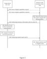
- FIG. 5 is an example signaling diagram illustrating the basic signaling steps from the perspective of the network node (e.g. location server 130) and the target device (e.g. UE 100) according to certain embodiments.
- Network node 130 and UE 110 can exchange capabilities information related to device integrity (steps 200, 201).
- the network node 130 can select an Alert Limit and/or Integrity Risk for the UE 100 (step 202).
- the Alert Limit and/or Integrity Risk can be associated with one or more PRS(s).
- the network node 130 can then provide the Alert Limit and/or Integrity Risk parameters with OTDOA assistance information to UE 110 (step 203).
- UE 110 monitors the Integrity Risk for its PRS(s) and obtains positioning measurements (step 204).
- the Protection Level can be computed in accordance with the received Integrity Risk parameter (step 205).
- UE 110 can then report the positioning measurements and the computed Protection Level (step 206). Accordingly, the network node 130 obtains positioning and/or integrity status (step
- step 206 can involve UE 110 providing OTDOA results along with uncertainty and quality of measurements. This can be further considered by the network node 130 to identify/determine the integrity of the estimated calculated positioning co-ordinates.
- UE 110 may include additional reports from, for example, a motion-sensor, barometric pressure sensor, etc., which can be further used by the network node 130 to determine the integrity of the estimation. If the UE 110 has been moving a lot during the measurements), it may lead to an unreliable reading.
- the network can assist a device in terms of alert limit and integrity risk for a PRS.
- the device can assess its positioning estimation and associated integrity level.
- the device can monitor the integrity risk of each PRS and determine which to select or avoid for obtaining positioning measurement(s).
- the network can receive the computed PL from the device(s) for future integrity risk estimations.
- the Alert Limit can be set for each application or use case. Therefore, it can be known by either the location server or the UE or by both, and it can be also shared from one to another by request.
- the network node can request for device integrity capabilities to understand whether the device is capable of processing the assistance information in this respect. Moreover, the type of UE can help the network to assess the AL for that particular device.
- the AL is the largest error allowable for safe operation.
- the AL can be configured in accordance with one or more of the following items:
- the AL can be reported to the device as an assistance data either automatically, when the device responds that it has integrity capability, or by a direct request from the device.
- a device may have the capability to set the AL by itself as well. In this case the device can report to the network on what AL it has assumed.
- the AL reporting can include the following example formats:
- the positioning Integrity Risk (IR) parameter is set by the location server and can be provided to the UE as an assistance information.
- the IR is the maximum probability of providing a positioning service (e.g. signal, measurement, etc.) that is out of tolerance without warning the user in a given period of time.
- the network node can set this parameter either for the complete set of assistance data or for each positioning reference signal (PRS) of the suggested reference and neighbor cells separately.
- PRS positioning reference signal
- the network node can configure the IR in accordance with one or more of the following parameters:
- the IR can be given either as an overall percentage value or a percentage value for each separate PRS of cells/beams as the OTDOA assistance information.
- the network node can send the AL and IR in one signal. In other embodiments, the network node can only send the IR to the device considering that the AL is assumed by the device.
- the device with the OTDOA assistance information starts performing measurements and it can be so that the selection of the cells for OTDOA measurement would be identified based on monitoring the IRs. Further, the Protection Level (PL) can be computed at the device based on the IR received from the network node. PL is the statistical error bound computed to guarantee that the probability of the absolute position error exceeding the PL number is smaller than or equal to the target integrity risk. The device reports this to the network node in the location information reporting together with the computed position estimation or the RSTD measurements in the case of UE-assisted OTDOA positioning.
- PL Protection Level
- the PL reporting can include the following example formats:
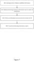
- Figure 7 is a flow chart illustrating a method which can be performed in a wireless device 110, such as a UE as described herein.
- the method can include:
- the wireless device can compute a Protection Level (PL) parameter based at least in part on the IR parameter received from the network.
- the PL parameter can indicate a statistical error bound computed to guarantee that the probability of the absolute position error exceeding said PL number is less than or equal to the IR.
- Step 330 The wireless device transmits a positioning information report to the network node.
- the positioning information can include its estimated position (e.g. the OTDOA results) and integrity-related information such as the computed PL parameter.
- the wireless device can communicate (e.g. transmit/receive messages) directly with a network node such as location server 130.
- messages and signals between the entities may be communicated via other nodes, such as radio access node (e.g. gNB, eNB) 120.
- radio access node e.g. gNB, eNB
- Figure 8 is a flow chart illustrating a method which can be performed in a network node 130, such as a location server as described herein.
- the method can include:
- the network node can determine the integrity (e.g. an "integrity status") of the estimated positioning co-ordinates in accordance with the received positioning information (e.g. the PL parameter).
- the network node 130 can communicate (e.g. transmit/receive messages) directly with a target wireless device 110.
- messages and signals between the entities may be communicated via other nodes, such as radio access node (e.g. gNB, eNB) 120.
- radio access node e.g. gNB, eNB
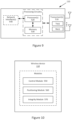
- FIG. 9 is a block diagram of an example wireless device, UE 110, in accordance with certain embodiments.
- UE 110 includes a transceiver 510, processor 520, and memory 530.
- the transceiver 510 facilitates transmitting wireless signals to and receiving wireless signals from radio access node 120 (e.g., via transmitter(s) (Tx), receiver(s) (Rx) and antenna(s)).
- the processor 520 executes instructions to provide some or all of the functionalities described above as being provided by UE, and the memory 530 stores the instructions executed by the processor 520.
- the processor 520 and the memory 530 form processing circuitry.
- the processor 520 can include any suitable combination of hardware to execute instructions and manipulate data to perform some or all of the described functions of a wireless device, such as the functions of UE 110 described above.
- the processor 520 may include, for example, one or more computers, one or more central processing units (CPUs), one or more microprocessors, one or more application specific integrated circuits (ASICs), one or more field programmable gate arrays (FPGAs) and/or other logic.
- the memory 530 is generally operable to store instructions, such as a computer program, software, an application including one or more of logic, rules, algorithms, code, tables, etc. and/or other instructions capable of being executed by a processor 520.
- Examples of memory 530 include computer memory (for example, Random Access Memory (RAM) or Read Only Memory (ROM)), mass storage media (for example, a hard disk), removable storage media (for example, a Compact Disk (CD) or a Digital Video Disk (DVD)), and/or or any other volatile or non-volatile, non-transitory computer-readable and/or computer-executable memory devices that store information, data, and/or instructions that may be used by the processor 520 of UE 110.
- RAM Random Access Memory
- ROM Read Only Memory
- mass storage media for example, a hard disk
- removable storage media for example, a Compact Disk (CD) or a Digital Video Disk (DVD)
- UE 110 may include additional components beyond those shown in Figure 9 that may be responsible for providing certain aspects of the wireless device's functionalities, including any of the functionalities described above and/or any additional functionalities (including any functionality necessary to support the solution described above).
- UE 110 may include input devices and circuits, output devices, and one or more synchronization units or circuits, which may be part of the processor 520.
- Input devices include mechanisms for entry of data into UE 110.
- input devices may include input mechanisms, such as a microphone, input elements, a display, etc.
- Output devices may include mechanisms for outputting data in audio, video and/or hard copy format.
- output devices may include a speaker, a display, etc.
- the wireless device UE 110 may comprise a series of modules configured to implement the functionalities of the wireless device described above.
- the wireless device 110 may comprise a control module 550 for receiving and interpreting control/configuration/capability information, a positioning module 560 for performing positioning measurements and calculating an estimated position, and an integrity module 570 for monitoring and determining the integrity associated with the positioning measurements.
- modules may be implemented as combination of hardware and software, for instance, the processor, memory and transceiver(s) of UE 110 shown in Figure 9 . Some embodiments may also include additional modules to support additional and/or optional functionalities.
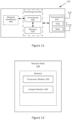
- FIG 11 is a block diagram of an exemplary network node 130.
- the exemplary node can be a location server or an access node, in accordance with certain embodiments.
- Network node 130 may include one or more of a transceiver 610, processor 620, memory 630, and network interface 640.
- the transceiver 610 facilitates transmitting wireless signals to and receiving wireless signals from wireless devices, such as UE 110 (e.g., via transmitter(s) (Tx), receiver(s) (Rx), and antenna(s)).
- the processor 620 executes instructions to provide some or all of the functionalities described above as being provided by network node 130, the memory 630 stores the instructions executed by the processor 620.
- the processor 620 and the memory 630 form processing circuitry.
- the network interface 640 can communicate signals to backend network components, such as a gateway, switch, router, Internet, Public Switched Telephone Network (PSTN), core network nodes or radio network controllers, etc.
- PSTN Public Switched Telephone Network
- the processor 620 can include any suitable combination of hardware to execute instructions and manipulate data to perform some or all of the described functions of network node 130, such as those described above.
- the processor 620 may include, for example, one or more computers, one or more central processing units (CPUs), one or more microprocessors, one or more application specific integrated circuits (ASICs), one or more field programmable gate arrays (FPGAs) and/or other logic.
- CPUs central processing units
- ASICs application specific integrated circuits
- FPGAs field programmable gate arrays
- the memory 630 is generally operable to store instructions, such as a computer program, software, an application including one or more of logic, rules, algorithms, code, tables, etc. and/or other instructions capable of being executed by a processor 620.
- Examples of memory 630 include computer memory (for example, Random Access Memory (RAM) or Read Only Memory (ROM)), mass storage media (for example, a hard disk), removable storage media (for example, a Compact Disk (CD) or a Digital Video Disk (DVD)), and/or or any other volatile or non-volatile, non-transitory computer-readable and/or computer-executable memory devices that store information.
- the network interface 640 is communicatively coupled to the processor 620 and may refer to any suitable device operable to receive input for node 130, send output from node 130, perform suitable processing of the input or output or both, communicate to other devices, or any combination of the preceding.
- the network interface 640 may include appropriate hardware (e.g., port, modem, network interface card, etc.) and software, including protocol conversion and data processing capabilities, to communicate through a network.
- network node 130 can include additional components beyond those shown in Figure 11 that may be responsible for providing certain aspects of the node's functionalities, including any of the functionalities described above and/or any additional functionalities (including any functionality necessary to support the solutions described above).
- the various different types of network nodes may include components having the same physical hardware but configured (e.g., via programming) to support different radio access technologies, or may represent partly or entirely different physical components.
- Processors, interfaces, and memory similar to those described with respect to Figure 11 may be included in other network nodes (such as UE 110, radio access node 120, etc.).
- Other network nodes may optionally include or not include a wireless interface (such as the transceiver described in Figure 11 ).
- the network node 130 may comprise a series of modules configured to implement the functionalities of the network node described above.
- the network node 130 can comprise a transceiver module 650 for transmitting and receiving positioning-related messages, such as capability requests/responses, positioning information and reports, and an integrity module 660 for determining integrity-related parameter(s) associated with a device and for determining the integrity associated with an estimated position of the device.
- positioning-related messages such as capability requests/responses, positioning information and reports
- an integrity module 660 for determining integrity-related parameter(s) associated with a device and for determining the integrity associated with an estimated position of the device.
- modules may be implemented as combination of hardware and software, for instance, the processor, memory and transceiver(s) of network node 130 shown in Figure 11 . Some embodiments may also include additional modules to support additional and/or optional functionalities.
- some network nodes e.g. UEs 110, radio access nodes 120, core network nodes 130, etc.
- some network nodes e.g. UEs 110, radio access nodes 120, core network nodes 130, etc.
- some or all the functions of a given network node are implemented as one or more virtual network functions (VNFs) running in virtual machines (VMs) hosted on a typically generic processing node 700 (or server).
- VNFs virtual network functions
- VMs virtual machines
- Processing node 700 generally comprises a hardware infrastructure 702 supporting a virtualization environment 704.
- the hardware infrastructure 702 generally comprises processing circuitry 706, a memory 708, and communication interface(s) 710.
- Processing circuitry 706 typically provides overall control of the hardware infrastructure 702 of the virtualized processing node 700. Hence, processing circuitry 706 is generally responsible for the various functions of the hardware infrastructure 702 either directly or indirectly via one or more other components of the processing node 700 (e.g. sending or receiving messages via the communication interface 710). The processing circuitry 706 is also responsible for enabling, supporting and managing the virtualization environment 704 in which the various VNFs are run. The processing circuitry 706 may include any suitable combination of hardware to enable the hardware infrastructure 702 of the virtualized processing node 700 to perform its functions.
- the processing circuitry 706 may comprise at least one processor 712 and at least one memory 714.
- processor 712 include, but are not limited to, a central processing unit (CPU), a graphical processing unit (GPU), and other forms of processing unit.
- memory 714 include, but are not limited to, Random Access Memory (RAM) and Read Only Memory (ROM).
- RAM Random Access Memory
- ROM Read Only Memory
- memory 714 is generally configured to store instructions or codes executable by processor 712, and possibly operational data.
- Processor 712 is then configured to execute the stored instructions and possibly create, transform, or otherwise manipulate data to enable the hardware infrastructure 702 of the virtualized processing node 700 to perform its functions.
- the processing circuity 706 may comprise, or further comprise, one or more application-specific integrated circuits (ASICs), one or more complex programmable logic device (CPLDs), one or more field-programmable gate arrays (FPGAs), or other forms of application-specific and/or programmable circuitry.
- ASICs application-specific integrated circuits
- CPLDs complex programmable logic device
- FPGAs field-programmable gate arrays
- the hardware infrastructure 702 of the virtualized processing node 700 may perform its functions without the need for instructions or codes as the necessary instructions may already be hardwired or preprogrammed into processing circuitry 706. Understandably, processing circuitry 706 may comprise a combination of processor(s) 712, memory(ies) 714, and other application-specific and/or programmable circuitry.
- the communication interface(s) 710 enable the virtualized processing node 700 to send messages to and receive messages from other network nodes (e.g., radio network nodes, other core network nodes, servers, etc.).
- the communication interface 710 generally comprises the necessary hardware and software to process messages received from the processing circuitry 706 to be sent by the virtualized processing node 700 into a format appropriate for the underlying transport network and, conversely, to process messages received from other network nodes over the underlying transport network into a format appropriate for the processing circuitry 706.
- communication interface 710 may comprise appropriate hardware, such as transport network interface(s) 716 (e.g., port, modem, network interface card, etc.), and software, including protocol conversion and data processing capabilities, to communicate with other network nodes.
- the virtualization environment 704 is enabled by instructions or codes stored on memory 708 and/or memory 714.
- the virtualization environment 704 generally comprises a virtualization layer 718 (also referred to as a hypervisor), at least one virtual machine 720, and at least one VNF 722.
- the functions of the processing node 700 may be implemented by one or more VNFs 722.
- Some embodiments may be represented as a software product stored in a machine-readable medium (also referred to as a computer-readable medium, a processor-readable medium, or a computer usable medium having a computer readable program code embodied therein).
- the machine-readable medium may be any suitable tangible medium including a magnetic, optical, or electrical storage medium including a diskette, compact disk read only memory (CD-ROM), digital versatile disc read only memory (DVD-ROM) memory device (volatile or non-volatile), or similar storage mechanism.
- the machine-readable medium may contain various sets of instructions, code sequences, configuration information, or other data, which, when executed, cause processing circuitry (e.g. a processor) to perform steps in a method according to one or more embodiments.
- processing circuitry e.g. a processor
- Software running from the machine-readable medium may interface with circuitry to perform the described tasks.
- the present description may comprise one or more of the following abbreviation:
Landscapes
- Engineering & Computer Science (AREA)
- Computer Networks & Wireless Communication (AREA)
- Signal Processing (AREA)
- Computer Security & Cryptography (AREA)
- Physics & Mathematics (AREA)
- General Physics & Mathematics (AREA)
- Radar, Positioning & Navigation (AREA)
- Remote Sensing (AREA)
- Mobile Radio Communication Systems (AREA)
Claims (12)
- Verfahren, das von einem Netzwerkknoten (130) durchgeführt wird, wobei das Verfahren umfasst:Bestimmen (202, 410) eines Integritätsrisikoparameters, IR-Parameters, der mit einer drahtlosen Vorrichtung (110) assoziiert ist, wobei der IR-Parameter eine maximale Wahrscheinlichkeit angibt, dass ein Positionsbestimmungsdienst außerhalb eines Toleranzbereichs bereitgestellt wird;Übertragen (203, 420) von Positionsbestimmungshilfsinformationen und des IR-Parameters an die drahtlose Vorrichtung; undEmpfangen (206, 430) einer geschätzten Position und eines Schutzstufenparameters, PL-Parameters, von der drahtlosen Vorrichtung, wobei der PL-Parameter eine statistische Fehlergrenze angibt, die berechnet wird, um zu gewährleisten, dass die Wahrscheinlichkeit, dass ein Positionsfehler die PL überschreitet, kleiner oder gleich dem IR ist,wobei:- der IR-Parameter mit einem oder mehreren Positionsbestimmungsreferenzsignalen, PRS, assoziiert ist; oder- der IR-Parameter gemäß mindestens einem von Folgenden bestimmt wird: einem Synchronisationsfehler des Netzwerkknotens; einem bedienenden Strahl.
- Verfahren, das von einem Netzwerkknoten (130) durchgeführt wird, wobei das Verfahren umfasst:Bestimmen (202, 410) eines Integritätsrisikoparameters, IR-Parameters, der mit einer drahtlosen Vorrichtung (110) assoziiert ist, wobei der IR-Parameter eine maximale Wahrscheinlichkeit angibt, dass ein Positionsbestimmungsdienst außerhalb eines Toleranzbereichs bereitgestellt wird;Übertragen (203, 420) von Positionsbestimmungshilfsinformationen und des IR-Parameters an die drahtlose Vorrichtung; undEmpfangen (206, 430) einer geschätzten Position und eines Schutzstufenparameters, PL-Parameters, von der drahtlosen Vorrichtung, wobei der PL-Parameter eine statistische Fehlergrenze angibt, die berechnet wird, um zu gewährleisten, dass die Wahrscheinlichkeit, dass ein Positionsfehler die PL überschreitet, kleiner oder gleich dem IR ist,wobei es sich bei den Positionsbestimmungshilfsinformationen um eines von Informationen bezüglich einer beobachteten Ankunftszeitdifferenz, OTDOA, oder Informationen bezüglich einer Downlink-Ankunftszeitdifferenz, DL-TDOA, handelt.
- Verfahren nach Anspruch 2, wobei der IR-Parameter mit einem vollständigen Satz von OTDOA- oder DL-TDOA-Werten assoziiert ist.
- Verfahren, das von einem Netzwerkknoten (130) durchgeführt wird, wobei das Verfahren umfasst:Bestimmen (202, 410) eines Integritätsrisikoparameters, IR-Parameters, der mit einer drahtlosen Vorrichtung (110) assoziiert ist, wobei der IR-Parameter eine maximale Wahrscheinlichkeit angibt, dass ein Positionsbestimmungsdienst außerhalb eines Toleranzbereichs bereitgestellt wird;Übertragen (203, 420) von Positionsbestimmungshilfsinformationen und des IR-Parameters an die drahtlose Vorrichtung; undEmpfangen (206, 430) einer geschätzten Position und eines Schutzstufenparameters, PL-Parameters, von der drahtlosen Vorrichtung, wobei der PL-Parameter eine statistische Fehlergrenze angibt, die berechnet wird, um zu gewährleisten, dass die Wahrscheinlichkeit, dass ein Positionsfehler die PL überschreitet, kleiner oder gleich dem IR ist,ferner umfassend:Bestimmen eines Alarmgrenzwertparameters, AL-Parameters, der mit der drahtlosen Vorrichtung assoziiert ist, wobei der AL-Parameter einen größten für einen sicheren Betrieb zulässigen Fehler angibt; undSenden des AL-Parameters an die drahtlose Vorrichtung.
- Verfahren nach Anspruch 4, wobei der AL-Parameter gemäß mindestens einem von Folgenden bestimmt wird: einem Typ der drahtlosen Vorrichtung; einer Bandbreite und Trägerfrequenz; einer Innen- oder Außenklassifizierung der drahtlosen Vorrichtung; Karteninformationen; und Geschwindigkeits-, Beschleunigungs- oder Sensorinformationen von der drahtlosen Vorrichtung.
- Netzwerkknoten (130), umfassend eine Funkschnittstelle und Verarbeitungsschaltungsanordnung, die zum Durchführen des Verfahrens nach einem der Ansprüche 1 bis 5 konfiguriert ist.
- Computerlesbares Medium (630), umfassend Codeabschnitte, die bei Ausführung auf einem Prozessor (620) des Netzwerkknotens (130) nach Anspruch 6 den Prozessor zum Durchführen des Verfahrens nach einem der Ansprüche 1 bis 5 konfigurieren.
- Verfahren, das von einer drahtlosen Vorrichtung (110) durchgeführt wird, wobei das Verfahren umfasst:Empfangen (203, 310) von Positionsbestimmungshilfsinformationen und eines Integritätsrisikoparameters, IR-Parameters, von einem Netzwerkknoten (130), wobei der IR-Parameter eine maximale Wahrscheinlichkeit angibt, dass ein Positionsbestimmungsdienst außerhalb eines Toleranzbereichs bereitgestellt wird;Durchführen (204, 320) von Positionsbestimmungsmessungen, um eine geschätzte Position der drahtlosen Vorrichtung zu bestimmen;Bestimmen (205) eines Schutzstufenparameters, PL-Parameters, wenigstens zum Teil basierend auf dem IR-Parameter, wobei der PL-Parameter eine statistische Fehlergrenze angibt, die berechnet wird, um zu gewährleisten, dass die Wahrscheinlichkeit, dass ein Positionsfehler die PL überschreitet, kleiner oder gleich dem IR ist, undÜbertragen (206, 330) der geschätzten Position und des PL-Parameters an den Netzwerkknoten,wobei:
das Verfahren ferner ein Überwachen (204) des IR-Parameters während des Durchführens der Positionsbestimmungsmessungen umfasst; oder- der IR-Parameter mit einem oder mehreren Positionsbestimmungsreferenzsignalen, PRS, assoziiert ist; oder- das Verfahren ferner ein Überwachen (204) des mit jedem PRS assoziierten IR-Parameters umfasst, um zu bestimmen, welches PRS in die Positionsbestimmungsmessungen einbezogen werden soll; oder- das Verfahren ferner ein Empfangen eines Alarmgrenzwertparameters, AL-Parameters, wobei der AL-Parameter den größten für einen sicheren Betrieb zulässigen Fehler angibt; und Überwachen des AL-Parameters während des Durchführens der Positionsbestimmungsmessungen umfasst. - Verfahren, das von einer drahtlosen Vorrichtung (110) durchgeführt wird, wobei das Verfahren umfasst:Empfangen (203, 310) von Positionsbestimmungshilfsinformationen und eines Integritätsrisikoparameters, IR-Parameters, von einem Netzwerkknoten (130), wobei der IR-Parameter eine maximale Wahrscheinlichkeit angibt, dass ein Positionsbestimmungsdienst außerhalb eines Toleranzbereichs bereitgestellt wird;Durchführen (204, 320) von Positionsbestimmungsmessungen, um eine geschätzte Position der drahtlosen Vorrichtung zu bestimmen;Bestimmen (205) eines Schutzstufenparameters, PL-Parameters, wenigstens zum Teil basierend auf dem IR-Parameter, wobei der PL-Parameter eine statistische Fehlergrenze angibt, die berechnet wird, um zu gewährleisten, dass die Wahrscheinlichkeit, dass ein Positionsfehler die PL überschreitet, kleiner oder gleich dem IR ist, undÜbertragen (206, 330) der geschätzten Position und des PL-Parameters an den Netzwerkknoten,wobei es sich bei den Positionsbestimmungshilfsinformationen um eines von Informationen bezüglich einer beobachteten Ankunftszeitdifferenz, OTDOA, oder Informationen bezüglich einer Downlink-Ankunftszeitdifferenz, DL-TDOA, handelt.
- Verfahren nach Anspruch 9, wobei der IR-Parameter mit einem vollständigen Satz von OTDOA- oder DL-TDOA-Werten assoziiert ist.
- Drahtlose Vorrichtung (110), umfassend eine Funkschnittstelle und Verarbeitungsschaltungsanordnung, die zum Durchführen des Verfahrens nach einem der Ansprüche 8 bis 10 konfiguriert ist.
- Computerlesbares Medium (530), umfassend Codeabschnitte, die bei Ausführung auf einem Prozessor (540) der drahtlosen Vorrichtung (110) nach Anspruch 11 den Prozessor zum Durchführen des Verfahrens nach einem der Ansprüche 8 bis 10 konfigurieren.
Applications Claiming Priority (2)
| Application Number | Priority Date | Filing Date | Title |
|---|---|---|---|
| US202063005068P | 2020-04-03 | 2020-04-03 | |
| PCT/IB2021/052752 WO2021198983A1 (en) | 2020-04-03 | 2021-04-01 | Network assistance positioning integrity reporting |
Publications (2)
| Publication Number | Publication Date |
|---|---|
| EP4128915A1 EP4128915A1 (de) | 2023-02-08 |
| EP4128915B1 true EP4128915B1 (de) | 2024-11-20 |
Family
ID=75478100
Family Applications (1)
| Application Number | Title | Priority Date | Filing Date |
|---|---|---|---|
| EP21718207.0A Active EP4128915B1 (de) | 2020-04-03 | 2021-04-01 | Meldung der integrität einer netzwerkunterstützungspositionierung |
Country Status (3)
| Country | Link |
|---|---|
| US (1) | US12273849B2 (de) |
| EP (1) | EP4128915B1 (de) |
| WO (1) | WO2021198983A1 (de) |
Families Citing this family (17)
| Publication number | Priority date | Publication date | Assignee | Title |
|---|---|---|---|---|
| US20230221401A1 (en) * | 2020-05-07 | 2023-07-13 | Telefonaktiebolaget Lm Ericsson (Publ) | Integrity for rat dependent positioning |
| EP4190054A1 (de) * | 2020-07-29 | 2023-06-07 | Sony Group Corporation | Verfahren zur erzeugung von positionsdaten |
| KR20230048377A (ko) | 2020-08-06 | 2023-04-11 | 텔레호낙티에볼라게트 엘엠 에릭슨(피유비엘) | 산업용 사물 인터넷에 대한 무결성을 정의하기 위한 방법들 및 시스템들 |
| KR20220136755A (ko) * | 2021-04-01 | 2022-10-11 | 삼성전자주식회사 | 무선 통신 시스템에서 포지셔닝 무결성을 지원하기 위한 방법 및 장치 |
| JP7771222B2 (ja) * | 2021-05-13 | 2025-11-17 | クゥアルコム・インコーポレイテッド | サイドリンク測位のための最小および最大測位範囲指示とゾーン識別子とをシグナリングすること |
| JPWO2023095803A1 (de) * | 2021-11-24 | 2023-06-01 | ||
| EP4461038A1 (de) * | 2022-01-07 | 2024-11-13 | Qualcomm Incorporated | Integritätsinformationen für funkzugangstechnologieabhängige positionierungshilfsdaten |
| WO2023151563A1 (zh) * | 2022-02-09 | 2023-08-17 | 华为技术有限公司 | 辅助定位方法及通信装置 |
| CA3206183A1 (en) * | 2022-07-12 | 2024-01-12 | Gts France Sas | Mac method for monitoring, with common bias compensation, the integrity of a point positioning process using virtual beacons |
| EP4413797A4 (de) * | 2022-07-18 | 2024-12-11 | ZTE Corporation | Systeme und verfahren zur verbesserung der positionierung von benutzergeräten |
| WO2024031378A1 (zh) * | 2022-08-09 | 2024-02-15 | 北京小米移动软件有限公司 | 错误源信息的发送和接收方法、装置、设备及存储介质 |
| WO2024031366A1 (zh) * | 2022-08-09 | 2024-02-15 | 北京小米移动软件有限公司 | 定位完整性的确定方法、装置、设备及介质 |
| CN117859305A (zh) * | 2022-08-09 | 2024-04-09 | 北京小米移动软件有限公司 | 错误源信息的发送方法、接收方法、装置、设备及介质 |
| EP4458073A4 (de) * | 2022-09-29 | 2025-11-19 | Zte Corp | Integrität von positionierungstechniken, die von funkzugang abhängen |
| CN118402214A (zh) | 2022-11-03 | 2024-07-26 | 中兴通讯股份有限公司 | 用于对用于定位估计的用户设备测量进行分类的方法、装置和系统 |
| US20240155548A1 (en) * | 2022-11-03 | 2024-05-09 | Nokia Technologies Oy | Reporting integrity measurement error distribution groups |
| AU2023405444B2 (en) * | 2023-04-07 | 2025-06-19 | Zte Corporation | Systems and methods for improving positioning with error source modeling |
Citations (1)
| Publication number | Priority date | Publication date | Assignee | Title |
|---|---|---|---|---|
| EP4109958A1 (de) * | 2020-02-21 | 2022-12-28 | Datang Mobile Communications Equipment Co., Ltd. | Verfahren, vorrichtung und vorrichtung zur verarbeitung von standortdiensten und medium |
Family Cites Families (2)
| Publication number | Priority date | Publication date | Assignee | Title |
|---|---|---|---|---|
| CN101598779B (zh) * | 2009-07-03 | 2011-07-27 | 北京航空航天大学 | 局域增强系统保护级完好性风险值的分配方法及装置 |
| US9843890B2 (en) * | 2016-03-18 | 2017-12-12 | Qualcomm Incorporated | Reliability in mobile device positioning in a crowdsourcing system |
-
2021
- 2021-04-01 EP EP21718207.0A patent/EP4128915B1/de active Active
- 2021-04-01 WO PCT/IB2021/052752 patent/WO2021198983A1/en not_active Ceased
- 2021-04-01 US US17/916,269 patent/US12273849B2/en active Active
Patent Citations (1)
| Publication number | Priority date | Publication date | Assignee | Title |
|---|---|---|---|---|
| EP4109958A1 (de) * | 2020-02-21 | 2022-12-28 | Datang Mobile Communications Equipment Co., Ltd. | Verfahren, vorrichtung und vorrichtung zur verarbeitung von standortdiensten und medium |
Also Published As
| Publication number | Publication date |
|---|---|
| WO2021198983A1 (en) | 2021-10-07 |
| US12273849B2 (en) | 2025-04-08 |
| US20230180171A1 (en) | 2023-06-08 |
| EP4128915A1 (de) | 2023-02-08 |
Similar Documents
| Publication | Publication Date | Title |
|---|---|---|
| EP4128915B1 (de) | Meldung der integrität einer netzwerkunterstützungspositionierung | |
| US11985091B2 (en) | Signalling support for NR positioning with aperiodic SRS configurations | |
| US20230180302A1 (en) | Random Access Procedure | |
| US20230221401A1 (en) | Integrity for rat dependent positioning | |
| US20220120840A1 (en) | Gnss assisted rrm measurements | |
| EP4193718A1 (de) | Konfiguration von positionierungssignalen und messungen zur reduzierung der latenz | |
| US12075466B2 (en) | Indication of downlink clear channel assessment failures | |
| EP4169277B1 (de) | Sicherer transfer von positionierungsintegrität kpi | |
| US11601241B2 (en) | Narrowband positioning reference signal configuration | |
| US20240243876A1 (en) | Collision handling for positioning reference signals | |
| US20220141885A1 (en) | Random Access Procedure | |
| WO2022028536A1 (en) | Methods and apparatus for data volume counting | |
| US20240205877A1 (en) | Methods, access node and network node for addressing ambiguities in angle of arrival estimation | |
| US20230199568A1 (en) | Quality of service management in a telecommunications network | |
| US12317096B2 (en) | Dynamic relocation of nodes in a cellular network | |
| US20210025960A1 (en) | Narrowband positioning reference signal generation for correlation properties | |
| US12408138B2 (en) | Methods and systems to define integrity for industrial internet of things |
Legal Events
| Date | Code | Title | Description |
|---|---|---|---|
| STAA | Information on the status of an ep patent application or granted ep patent |
Free format text: STATUS: UNKNOWN |
|
| STAA | Information on the status of an ep patent application or granted ep patent |
Free format text: STATUS: THE INTERNATIONAL PUBLICATION HAS BEEN MADE |
|
| PUAI | Public reference made under article 153(3) epc to a published international application that has entered the european phase |
Free format text: ORIGINAL CODE: 0009012 |
|
| STAA | Information on the status of an ep patent application or granted ep patent |
Free format text: STATUS: REQUEST FOR EXAMINATION WAS MADE |
|
| 17P | Request for examination filed |
Effective date: 20221028 |
|
| AK | Designated contracting states |
Kind code of ref document: A1 Designated state(s): AL AT BE BG CH CY CZ DE DK EE ES FI FR GB GR HR HU IE IS IT LI LT LU LV MC MK MT NL NO PL PT RO RS SE SI SK SM TR |
|
| DAV | Request for validation of the european patent (deleted) | ||
| DAX | Request for extension of the european patent (deleted) | ||
| STAA | Information on the status of an ep patent application or granted ep patent |
Free format text: STATUS: EXAMINATION IS IN PROGRESS |
|
| 17Q | First examination report despatched |
Effective date: 20230713 |
|
| REG | Reference to a national code |
Ref country code: DE Ref legal event code: R079 Free format text: PREVIOUS MAIN CLASS: H04W0064000000 Ipc: G01S0005000000 Ref country code: DE Ref legal event code: R079 Ref document number: 602021022084 Country of ref document: DE Free format text: PREVIOUS MAIN CLASS: H04W0064000000 Ipc: G01S0005000000 |
|
| GRAP | Despatch of communication of intention to grant a patent |
Free format text: ORIGINAL CODE: EPIDOSNIGR1 |
|
| STAA | Information on the status of an ep patent application or granted ep patent |
Free format text: STATUS: GRANT OF PATENT IS INTENDED |
|
| RIC1 | Information provided on ipc code assigned before grant |
Ipc: G01S 5/02 20100101ALI20240129BHEP Ipc: H04W 64/00 20090101ALI20240129BHEP Ipc: H04W 88/02 20090101ALI20240129BHEP Ipc: H04W 88/08 20090101ALI20240129BHEP Ipc: H04W 88/18 20090101ALI20240129BHEP Ipc: G01S 5/00 20060101AFI20240129BHEP |
|
| INTG | Intention to grant announced |
Effective date: 20240306 |
|
| GRAJ | Information related to disapproval of communication of intention to grant by the applicant or resumption of examination proceedings by the epo deleted |
Free format text: ORIGINAL CODE: EPIDOSDIGR1 |
|
| STAA | Information on the status of an ep patent application or granted ep patent |
Free format text: STATUS: EXAMINATION IS IN PROGRESS |
|
| GRAP | Despatch of communication of intention to grant a patent |
Free format text: ORIGINAL CODE: EPIDOSNIGR1 |
|
| STAA | Information on the status of an ep patent application or granted ep patent |
Free format text: STATUS: GRANT OF PATENT IS INTENDED |
|
| INTC | Intention to grant announced (deleted) | ||
| INTG | Intention to grant announced |
Effective date: 20240528 |
|
| GRAS | Grant fee paid |
Free format text: ORIGINAL CODE: EPIDOSNIGR3 |
|
| GRAA | (expected) grant |
Free format text: ORIGINAL CODE: 0009210 |
|
| STAA | Information on the status of an ep patent application or granted ep patent |
Free format text: STATUS: THE PATENT HAS BEEN GRANTED |
|
| AK | Designated contracting states |
Kind code of ref document: B1 Designated state(s): AL AT BE BG CH CY CZ DE DK EE ES FI FR GB GR HR HU IE IS IT LI LT LU LV MC MK MT NL NO PL PT RO RS SE SI SK SM TR |
|
| REG | Reference to a national code |
Ref country code: GB Ref legal event code: FG4D |
|
| REG | Reference to a national code |
Ref country code: CH Ref legal event code: EP |
|
| REG | Reference to a national code |
Ref country code: DE Ref legal event code: R096 Ref document number: 602021022084 Country of ref document: DE |
|
| REG | Reference to a national code |
Ref country code: IE Ref legal event code: FG4D |
|
| REG | Reference to a national code |
Ref country code: LT Ref legal event code: MG9D |
|
| REG | Reference to a national code |
Ref country code: NL Ref legal event code: MP Effective date: 20241120 |
|
| PG25 | Lapsed in a contracting state [announced via postgrant information from national office to epo] |
Ref country code: PT Free format text: LAPSE BECAUSE OF FAILURE TO SUBMIT A TRANSLATION OF THE DESCRIPTION OR TO PAY THE FEE WITHIN THE PRESCRIBED TIME-LIMIT Effective date: 20250320 Ref country code: IS Free format text: LAPSE BECAUSE OF FAILURE TO SUBMIT A TRANSLATION OF THE DESCRIPTION OR TO PAY THE FEE WITHIN THE PRESCRIBED TIME-LIMIT Effective date: 20250320 Ref country code: HR Free format text: LAPSE BECAUSE OF FAILURE TO SUBMIT A TRANSLATION OF THE DESCRIPTION OR TO PAY THE FEE WITHIN THE PRESCRIBED TIME-LIMIT Effective date: 20241120 |
|
| PG25 | Lapsed in a contracting state [announced via postgrant information from national office to epo] |
Ref country code: FI Free format text: LAPSE BECAUSE OF FAILURE TO SUBMIT A TRANSLATION OF THE DESCRIPTION OR TO PAY THE FEE WITHIN THE PRESCRIBED TIME-LIMIT Effective date: 20241120 Ref country code: NL Free format text: LAPSE BECAUSE OF FAILURE TO SUBMIT A TRANSLATION OF THE DESCRIPTION OR TO PAY THE FEE WITHIN THE PRESCRIBED TIME-LIMIT Effective date: 20241120 |
|
| REG | Reference to a national code |
Ref country code: AT Ref legal event code: MK05 Ref document number: 1744053 Country of ref document: AT Kind code of ref document: T Effective date: 20241120 |
|
| PG25 | Lapsed in a contracting state [announced via postgrant information from national office to epo] |
Ref country code: BG Free format text: LAPSE BECAUSE OF FAILURE TO SUBMIT A TRANSLATION OF THE DESCRIPTION OR TO PAY THE FEE WITHIN THE PRESCRIBED TIME-LIMIT Effective date: 20241120 |
|
| PG25 | Lapsed in a contracting state [announced via postgrant information from national office to epo] |
Ref country code: ES Free format text: LAPSE BECAUSE OF FAILURE TO SUBMIT A TRANSLATION OF THE DESCRIPTION OR TO PAY THE FEE WITHIN THE PRESCRIBED TIME-LIMIT Effective date: 20241120 |
|
| PG25 | Lapsed in a contracting state [announced via postgrant information from national office to epo] |
Ref country code: NO Free format text: LAPSE BECAUSE OF FAILURE TO SUBMIT A TRANSLATION OF THE DESCRIPTION OR TO PAY THE FEE WITHIN THE PRESCRIBED TIME-LIMIT Effective date: 20250220 |
|
| PG25 | Lapsed in a contracting state [announced via postgrant information from national office to epo] |
Ref country code: AT Free format text: LAPSE BECAUSE OF FAILURE TO SUBMIT A TRANSLATION OF THE DESCRIPTION OR TO PAY THE FEE WITHIN THE PRESCRIBED TIME-LIMIT Effective date: 20241120 Ref country code: GR Free format text: LAPSE BECAUSE OF FAILURE TO SUBMIT A TRANSLATION OF THE DESCRIPTION OR TO PAY THE FEE WITHIN THE PRESCRIBED TIME-LIMIT Effective date: 20250221 Ref country code: LV Free format text: LAPSE BECAUSE OF FAILURE TO SUBMIT A TRANSLATION OF THE DESCRIPTION OR TO PAY THE FEE WITHIN THE PRESCRIBED TIME-LIMIT Effective date: 20241120 |
|
| PG25 | Lapsed in a contracting state [announced via postgrant information from national office to epo] |
Ref country code: PL Free format text: LAPSE BECAUSE OF FAILURE TO SUBMIT A TRANSLATION OF THE DESCRIPTION OR TO PAY THE FEE WITHIN THE PRESCRIBED TIME-LIMIT Effective date: 20241120 |
|
| PG25 | Lapsed in a contracting state [announced via postgrant information from national office to epo] |
Ref country code: RS Free format text: LAPSE BECAUSE OF FAILURE TO SUBMIT A TRANSLATION OF THE DESCRIPTION OR TO PAY THE FEE WITHIN THE PRESCRIBED TIME-LIMIT Effective date: 20250220 |
|
| PG25 | Lapsed in a contracting state [announced via postgrant information from national office to epo] |
Ref country code: SM Free format text: LAPSE BECAUSE OF FAILURE TO SUBMIT A TRANSLATION OF THE DESCRIPTION OR TO PAY THE FEE WITHIN THE PRESCRIBED TIME-LIMIT Effective date: 20241120 |
|
| PGFP | Annual fee paid to national office [announced via postgrant information from national office to epo] |
Ref country code: DE Payment date: 20250429 Year of fee payment: 5 |
|
| PG25 | Lapsed in a contracting state [announced via postgrant information from national office to epo] |
Ref country code: DK Free format text: LAPSE BECAUSE OF FAILURE TO SUBMIT A TRANSLATION OF THE DESCRIPTION OR TO PAY THE FEE WITHIN THE PRESCRIBED TIME-LIMIT Effective date: 20241120 |
|
| PGFP | Annual fee paid to national office [announced via postgrant information from national office to epo] |
Ref country code: GB Payment date: 20250428 Year of fee payment: 5 |
|
| PG25 | Lapsed in a contracting state [announced via postgrant information from national office to epo] |
Ref country code: EE Free format text: LAPSE BECAUSE OF FAILURE TO SUBMIT A TRANSLATION OF THE DESCRIPTION OR TO PAY THE FEE WITHIN THE PRESCRIBED TIME-LIMIT Effective date: 20241120 |
|
| PG25 | Lapsed in a contracting state [announced via postgrant information from national office to epo] |
Ref country code: RO Free format text: LAPSE BECAUSE OF FAILURE TO SUBMIT A TRANSLATION OF THE DESCRIPTION OR TO PAY THE FEE WITHIN THE PRESCRIBED TIME-LIMIT Effective date: 20241120 |
|
| PG25 | Lapsed in a contracting state [announced via postgrant information from national office to epo] |
Ref country code: SK Free format text: LAPSE BECAUSE OF FAILURE TO SUBMIT A TRANSLATION OF THE DESCRIPTION OR TO PAY THE FEE WITHIN THE PRESCRIBED TIME-LIMIT Effective date: 20241120 |
|
| PG25 | Lapsed in a contracting state [announced via postgrant information from national office to epo] |
Ref country code: CZ Free format text: LAPSE BECAUSE OF FAILURE TO SUBMIT A TRANSLATION OF THE DESCRIPTION OR TO PAY THE FEE WITHIN THE PRESCRIBED TIME-LIMIT Effective date: 20241120 |
|
| PG25 | Lapsed in a contracting state [announced via postgrant information from national office to epo] |
Ref country code: IT Free format text: LAPSE BECAUSE OF FAILURE TO SUBMIT A TRANSLATION OF THE DESCRIPTION OR TO PAY THE FEE WITHIN THE PRESCRIBED TIME-LIMIT Effective date: 20241120 |
|
| REG | Reference to a national code |
Ref country code: DE Ref legal event code: R097 Ref document number: 602021022084 Country of ref document: DE |
|
| PG25 | Lapsed in a contracting state [announced via postgrant information from national office to epo] |
Ref country code: SE Free format text: LAPSE BECAUSE OF FAILURE TO SUBMIT A TRANSLATION OF THE DESCRIPTION OR TO PAY THE FEE WITHIN THE PRESCRIBED TIME-LIMIT Effective date: 20241120 |
|
| PLBE | No opposition filed within time limit |
Free format text: ORIGINAL CODE: 0009261 |
|
| STAA | Information on the status of an ep patent application or granted ep patent |
Free format text: STATUS: NO OPPOSITION FILED WITHIN TIME LIMIT |
|
| 26N | No opposition filed |
Effective date: 20250821 |
|
| REG | Reference to a national code |
Ref country code: CH Ref legal event code: H13 Free format text: ST27 STATUS EVENT CODE: U-0-0-H10-H13 (AS PROVIDED BY THE NATIONAL OFFICE) Effective date: 20251125 |
|
| PG25 | Lapsed in a contracting state [announced via postgrant information from national office to epo] |
Ref country code: LU Free format text: LAPSE BECAUSE OF NON-PAYMENT OF DUE FEES Effective date: 20250401 |
|
| PG25 | Lapsed in a contracting state [announced via postgrant information from national office to epo] |
Ref country code: MC Free format text: LAPSE BECAUSE OF FAILURE TO SUBMIT A TRANSLATION OF THE DESCRIPTION OR TO PAY THE FEE WITHIN THE PRESCRIBED TIME-LIMIT Effective date: 20241120 |
|
| REG | Reference to a national code |
Ref country code: BE Ref legal event code: MM Effective date: 20250430 |
|
| PG25 | Lapsed in a contracting state [announced via postgrant information from national office to epo] |
Ref country code: FR Free format text: LAPSE BECAUSE OF NON-PAYMENT OF DUE FEES Effective date: 20250430 |
|
| PG25 | Lapsed in a contracting state [announced via postgrant information from national office to epo] |
Ref country code: BE Free format text: LAPSE BECAUSE OF NON-PAYMENT OF DUE FEES Effective date: 20250430 |
|
| PG25 | Lapsed in a contracting state [announced via postgrant information from national office to epo] |
Ref country code: CH Free format text: LAPSE BECAUSE OF NON-PAYMENT OF DUE FEES Effective date: 20250430 |