EP4128727B1 - Bistabiles scharnier mit determinanter bewegung - Google Patents
Bistabiles scharnier mit determinanter bewegung Download PDFInfo
- Publication number
- EP4128727B1 EP4128727B1 EP20719884.7A EP20719884A EP4128727B1 EP 4128727 B1 EP4128727 B1 EP 4128727B1 EP 20719884 A EP20719884 A EP 20719884A EP 4128727 B1 EP4128727 B1 EP 4128727B1
- Authority
- EP
- European Patent Office
- Prior art keywords
- pivot point
- hinge
- link
- relative
- around
- Prior art date
- Legal status (The legal status is an assumption and is not a legal conclusion. Google has not performed a legal analysis and makes no representation as to the accuracy of the status listed.)
- Active
Links
Images
Classifications
-
- G—PHYSICS
- G06—COMPUTING OR CALCULATING; COUNTING
- G06F—ELECTRIC DIGITAL DATA PROCESSING
- G06F1/00—Details not covered by groups G06F3/00 - G06F13/00 and G06F21/00
- G06F1/16—Constructional details or arrangements
- G06F1/1613—Constructional details or arrangements for portable computers
- G06F1/1615—Constructional details or arrangements for portable computers with several enclosures having relative motions, each enclosure supporting at least one I/O or computing function
- G06F1/1616—Constructional details or arrangements for portable computers with several enclosures having relative motions, each enclosure supporting at least one I/O or computing function with folding flat displays, e.g. laptop computers or notebooks having a clamshell configuration, with body parts pivoting to an open position around an axis parallel to the plane they define in closed position
- G06F1/1618—Constructional details or arrangements for portable computers with several enclosures having relative motions, each enclosure supporting at least one I/O or computing function with folding flat displays, e.g. laptop computers or notebooks having a clamshell configuration, with body parts pivoting to an open position around an axis parallel to the plane they define in closed position the display being foldable up to the back of the other housing with a single degree of freedom, e.g. by 360° rotation over the axis defined by the rear edge of the base enclosure
-
- G—PHYSICS
- G06—COMPUTING OR CALCULATING; COUNTING
- G06F—ELECTRIC DIGITAL DATA PROCESSING
- G06F1/00—Details not covered by groups G06F3/00 - G06F13/00 and G06F21/00
- G06F1/16—Constructional details or arrangements
- G06F1/1613—Constructional details or arrangements for portable computers
- G06F1/1615—Constructional details or arrangements for portable computers with several enclosures having relative motions, each enclosure supporting at least one I/O or computing function
- G06F1/1616—Constructional details or arrangements for portable computers with several enclosures having relative motions, each enclosure supporting at least one I/O or computing function with folding flat displays, e.g. laptop computers or notebooks having a clamshell configuration, with body parts pivoting to an open position around an axis parallel to the plane they define in closed position
- G06F1/162—Constructional details or arrangements for portable computers with several enclosures having relative motions, each enclosure supporting at least one I/O or computing function with folding flat displays, e.g. laptop computers or notebooks having a clamshell configuration, with body parts pivoting to an open position around an axis parallel to the plane they define in closed position changing, e.g. reversing, the face orientation of the screen with a two degrees of freedom mechanism, e.g. for folding into tablet PC like position or orienting towards the direction opposite to the user to show to a second user
-
- G—PHYSICS
- G06—COMPUTING OR CALCULATING; COUNTING
- G06F—ELECTRIC DIGITAL DATA PROCESSING
- G06F1/00—Details not covered by groups G06F3/00 - G06F13/00 and G06F21/00
- G06F1/16—Constructional details or arrangements
- G06F1/1613—Constructional details or arrangements for portable computers
- G06F1/1633—Constructional details or arrangements of portable computers not specific to the type of enclosures covered by groups G06F1/1615 - G06F1/1626
- G06F1/1675—Miscellaneous details related to the relative movement between the different enclosures or enclosure parts
- G06F1/1681—Details related solely to hinges
-
- H—ELECTRICITY
- H04—ELECTRIC COMMUNICATION TECHNIQUE
- H04M—TELEPHONIC COMMUNICATION
- H04M1/00—Substation equipment, e.g. for use by subscribers
- H04M1/02—Constructional features of telephone sets
- H04M1/0202—Portable telephone sets, e.g. cordless phones, mobile phones or bar type handsets
- H04M1/0206—Portable telephones comprising a plurality of mechanically joined movable body parts, e.g. hinged housings
- H04M1/0208—Portable telephones comprising a plurality of mechanically joined movable body parts, e.g. hinged housings characterized by the relative motions of the body parts
- H04M1/0214—Foldable telephones, i.e. with body parts pivoting to an open position around an axis parallel to the plane they define in closed position
- H04M1/0222—Foldable in two directions, i.e. using a two degree of freedom hinge
-
- E—FIXED CONSTRUCTIONS
- E05—LOCKS; KEYS; WINDOW OR DOOR FITTINGS; SAFES
- E05Y—INDEXING SCHEME ASSOCIATED WITH SUBCLASSES E05D AND E05F, RELATING TO CONSTRUCTION ELEMENTS, ELECTRIC CONTROL, POWER SUPPLY, POWER SIGNAL OR TRANSMISSION, USER INTERFACES, MOUNTING OR COUPLING, DETAILS, ACCESSORIES, AUXILIARY OPERATIONS NOT OTHERWISE PROVIDED FOR, APPLICATION THEREOF
- E05Y2999/00—Subject-matter not otherwise provided for in this subclass
-
- G—PHYSICS
- G06—COMPUTING OR CALCULATING; COUNTING
- G06F—ELECTRIC DIGITAL DATA PROCESSING
- G06F1/00—Details not covered by groups G06F3/00 - G06F13/00 and G06F21/00
- G06F1/16—Constructional details or arrangements
- G06F1/1613—Constructional details or arrangements for portable computers
- G06F1/1615—Constructional details or arrangements for portable computers with several enclosures having relative motions, each enclosure supporting at least one I/O or computing function
- G06F1/1616—Constructional details or arrangements for portable computers with several enclosures having relative motions, each enclosure supporting at least one I/O or computing function with folding flat displays, e.g. laptop computers or notebooks having a clamshell configuration, with body parts pivoting to an open position around an axis parallel to the plane they define in closed position
-
- G—PHYSICS
- G06—COMPUTING OR CALCULATING; COUNTING
- G06F—ELECTRIC DIGITAL DATA PROCESSING
- G06F1/00—Details not covered by groups G06F3/00 - G06F13/00 and G06F21/00
- G06F1/16—Constructional details or arrangements
- G06F1/1613—Constructional details or arrangements for portable computers
- G06F1/1633—Constructional details or arrangements of portable computers not specific to the type of enclosures covered by groups G06F1/1615 - G06F1/1626
- G06F1/1675—Miscellaneous details related to the relative movement between the different enclosures or enclosure parts
- G06F1/1679—Miscellaneous details related to the relative movement between the different enclosures or enclosure parts for locking or maintaining the movable parts of the enclosure in a fixed position, e.g. latching mechanism at the edge of the display in a laptop or for the screen protective cover of a PDA
Definitions
- Hybrid computers may act as a tablet computer or a laptop computer.
- Some hybrid computers are clamshell devices that are used in different orientations. For example, some hybrid computers may be oriented with a touch-sensitive surface laid flat against the table or other surfaces on which the user is operating the hybrid computer. Some hybrid computers have a keyboard in a first portion of the computer and a touch-sensitive display in a second portion of the computer, where the first portion and the second portion are connected by a hinge.
- Conventional hinges have a single pivot point, limiting the geometries at which the first portion and second portion may be positioned. Some conventional hinges will not allow the first portion and second portion to be oriented at greater than 180°. Other multiple pivot hinges allow for motion of the first portion and second portion of the hybrid computer past 180° but provide no control over which pivot point within the hinge is active during the movement of the hinge.
- a multiple pivot hinge with indeterminant motion does not control an active hinge, resulting in possible damage to the hybrid computer, rotation of a pivot point with a pinched or kink wire, and flexion of a keyboard or touch-sensitive surface when part of the first portion or second portion of the hybrid computer is not flat on the table or other surfaces.
- US 2018/0044958 A1 discloses an hinge which includes an internal slider and/or an external slider 114.
- US 2019/029135 A1 describes a hinge which may include a first case connection connected to a first case and a second case connection connected to a second case.
- This disclosure generally relates to electronic device hinges. More particularly, this disclosure generally relates to apparatuses, systems, and methods for selectively changing the axis of rotation of a hinge to allow an electronic device to achieve a variety of postures for use and for transport or storage.
- a hinge for an electronic device may have a plurality of pivot points.
- the hinge may pivot at only one of the pivot points at a time. At any given time, at least one of the pivot points may be locked, such that application of force to a side of the hinge may result in only one of the pivot points rotating at a time.
- the controlled movement of specific pivot points in the hinge is known as determinant motion.
- only one pivot point may be free to rotate.
- the pivot points may both be able to rotate, but the pivot points have different resistance.
- the different resistances around each rotational axis produce a preferential rotation around the axis or pivot point with a lower resistance at that position in the range of motion of the hinge.
- the lower resistance pivot point functions as the active pivot point.
- the resistance may be different in different rotational directions or at different positions within the rotational range of motion.
- a laptop having a hinge with fully determinant motion may move from a closed position (e.g., a 0° relationship between the screen and the keyboard of the laptop) to an open position (e.g., a 90° relationship between the screen and the keyboard of the laptop) with rotation only about a first pivot point. Movement of the hinge beyond the 90° position may lock the first pivot point and unlock the second pivot point, such that force applied to the hinge rotates about the second pivot point up to a flat position (e.g., a 180° relationship between the screen and the keyboard of the laptop).
- a closed position e.g., a 0° relationship between the screen and the keyboard of the laptop
- an open position e.g., a 90° relationship between the screen and the keyboard of the laptop
- Movement of the hinge beyond the 90° position may lock the first pivot point and unlock the second pivot point, such that force applied to the hinge rotates about the second pivot point up to a flat position (e.g., a 180° relationship between the screen and the keyboard of
- Determinant motion up to 90° may ensure that the active pivot point is positioned to extend the footprint of the device.
- stability of a laptop or other clamshell device may be at least partially based on how large the dimensions of the device's footprint are.
- the portion of the hinge between the first pivot point and the second pivot point can be positioned in line with the first body of the device (e.g., the keyboard of a laptop)
- the base upon which the device rests becomes larger and the center of mass of the device is lower than if the active pivot point is the second pivot point nearer the second body of the device (e.g., the display of a laptop).
- Determinant motion up to 180° may ensure that the device may move from a clamshell configuration at a 0° position to a fully flat configuration predictably and reliably.
- a hybrid laptop may have a touch-sensitive display or surface incorporated into one or both bodies of the device. Applying force or pressure to the touch-sensitive surface without being flat against a table or other supporting surfaces may flex or damage the laptop or the hinge.
- a bistable hinge may behave differently when the first portion of the device (e.g., the display) is connected to the hinge compared to when the first portion is disconnected or otherwise moved away from the hinge.
- the hinge may provide determinant motion around both pivot points back to the original clamshell configuration to close the laptop when the display is connected to the hinge.
- the display may be removed, rotated, or translated relative to the hinge while open to change the device into a tablet configuration.
- closing the hinge may result in rotation about only one of the pivot points and allow the device to enter a tablet or nested configuration with a smaller height of the hinge.
- FIG. 1 is a perspective view of a hinge 100 that connects a first body 102 of an electronic device to a second body 104 of the electronic device.
- the hinge 100 includes a first pivot point 106 and a second pivot point 108.
- the first pivot point 106 and the second pivot point 108 of the hinge 100 are connected by a link 110.
- the link 110 can move the second pivot point 108.
- the first pivot point 106 connected to the first body 102 e.g., the display of the electronic device
- the first pivot point 106 or the second pivot point 108 will be the active pivot point.
- a hinge 100 may connect a first body 102 of an electronic device to a second body 104 of the electronic device.
- the first body 102 may house a display, such as a touchscreen display while the second body 104 may house one or more computing components, such as a CPU, a GPU, one or more storage devices, one or more input devices, a power supply, or other computing components that may be configured to communicate with (e.g., receive information from, send information to, or send power to) the display in the first body 102.
- the hinge 100 may allow the first body 102 and second body 104 to communicate data or electrical signals through the hinge 100. Determinant motion of the hinge 100 can reduce the likelihood of damage to the data or electrical conduits that provide the data or electrical communication across the hinge 100.
- the motion of the hinge 100 may change depending on the presence and/or position of the first body 102 or of another body relative to the hinge 100.
- the display may be supported by and separable from the first body 102.
- removing or moving the display of the electronic device changes the mode of the hinge 100, such that the hinge 100 closes and/or opens differently when the display is not connected to the first body 102.
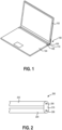
- a hinge 200 may have a closed position with the first body 202 and second body 204 oriented at a substantially 0° relationship to one another. While the present disclosure describes the operation of a hinge between 0° and 180°, it should be understood that in other embodiments, a hinge according to the present disclosure may be configured to operate within any range from 0° to 360°, such as 0° to 135°, 30° to 120°, 45° to 315°, or any other range of angles between the first body and second body.
- the hinge 200 may pivot around a first pivot point 206 and a second pivot point 208 with a link 210 between the first pivot point 206 and second pivot point 208.
- the link 210 may be any length to provide sufficient clearance between the first body 202 and second body 204 during operation of the hinge 200.
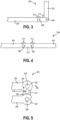
- FIG. 3 illustrates the embodiment of a hinge 200 of FIG. 2 rotated about the second pivot point 208 such that the first body 202 and the second body 204 are oriented at a 90° relationship to one another.
- the first pivot point 206 may be locked at (or remain at) a first pivot point angle 212 during movement of the second pivot point 208 until the second pivot point reaches a predetermined second pivot point angle 214, such as 180°.
- the initial rotation about the second pivot point 208 extends the footprint of the electronic device by effectively adding the length of the link 210 to the second body 204. This may allow the electronic device to be more stable compared to a hinge with indeterminant motion or a hinge that rotates about the first pivot point 206 before the second pivot point 208.
- the second pivot point 208 may lock and the first pivot point 206 may unlock.
- the hinge 200 may then rotate about the first pivot point 206 until the first pivot point angle 212 reaches a predetermined position, such as 180°, as shown in FIG. 4 .
- the first body 202, link 210 and the second body 204 may lie in a single plane.
- the first pivot point 206 or the second pivot point 208 is a friction hinge.
- a greater amount of force may be applied to the hinge 200 to move the hinge 200 about the first pivot point 206 than an amount of force needed to move the hinge 200 about the second pivot point 208.
- a greater amount of force may be applied to the hinge 200 to move the hinge 200 about the second pivot point 208 than an amount of force needed to move the hinge 200 about the first pivot point 206.
- the hinge includes a one-way bearing that provides different resistance in different rotational directions.
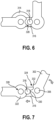
- FIG. 5 through FIG. 8 illustrate an embodiment of a hinge 300 that provides determinant motion up to 180° as illustrated in FIG. 2 through 4 .
- FIG. 5 illustrates the hinge 300 in the closed configuration with a first body 302 and a second body 304 at a 0° orientation from one another.
- the first body 302 is movable about a first pivot point 306 and the second body 304 is movable about a second pivot point 308.
- the first pivot point 306 is locked by a follower 318 protruding from an internal slider 316.
- the first body 302 cannot rotate about the first pivot point 306 because the first cam 320 has a cam surface 324 thereon, and the follower 318 is positioned in the cam surface 324.
- the follower 318 (and associated internal slider 316) may be moveable relative to the first pivot point, but the second cam 322 is positioned to limit and/or prevent movement of the follower 318.
- the hinge 300 may move about the second pivot point 308 as the follower 318 may move along the outer surface 326 of the second cam 322 until the second pivot point angle 314 reaches 180°, as shown in FIG. 6 .
- the follower 316 may align with the cam surface 328 of the second cam 322.
- the cam surface 328 of the second cam 322 may provide clearance for the follower 318 and associated internal slider 316 to move relative to the pivot points 306, 308.
- FIG. 7 illustrates the movement of the first body 302 about the first pivot point 306 urging the follower 318 and associated internal slider 312 toward the second cam 322.
- the cam surface 324 of the first cam 320 has a release edge 332 and a drive edge 330.
- the release edge 332 is configured to limit and/or prevent rotation of the first cam 320 relative to the follower 318 when the follower 318 is positioned in the cam surface 324 of the first cam 320.
- the drive edge 330 is rounded to facilitate the movement of the follower 318 away from the first cam 320 when the first cam 320 rotates about the first pivot point 306.
- the drive edge 330 of the first cam 320 may urge the follower 318 toward the second cam 322 upon rotation of the first cam 320.
- the release edge 332 may rotate away from the follower 318.
- the drive edge 330 may be rounded such that the drive edge 330 remains in contact with the follower 318 through an amount of rotation of the first cam 320 about the first pivot point 306.
- the first cam 320 may rotate about the first pivot point 306 up to 45° before the drive edge 330 passes the follower 318.
- the first cam 320 may rotate about the first pivot point 306 up to 40° before the drive edge 330 passes the follower 318.
- the first cam 320 may rotate about the first pivot point 306 up to 30° before the drive edge 330 passes the follower 318.
- the first cam 320 may rotate about the first pivot point 306 up to 20° before the drive edge 330 passes the follower 318.
- the follower 318 may be received by the cam surface 328 of the second cam 322 and the follower 318 may no longer limit the rotation of the first cam 320 about the first pivot point 306, unlocking the first pivot point 306 and allowing the first body 302 and first cam 320 to rotate freely with the follower 318 adjacent an outer surface 334 of the first cam 320.
- the first body 302 and first cam 320 may rotate until the first pivot point angle 312 is 180° and the first body 302 and second body 304 lie in a single plane (or another predetermined angle).
- a hinge according to the present disclosure may have more than two cams and/or more than one follower to provide a plurality of locks.
- a plurality of locks may provide determinant motion over a larger range of orientations and/or in both rotational directions of the hinge.
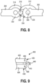
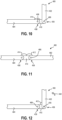
- FIG. 9 through FIG. 11 illustrate another embodiment of a hinge for providing determinant motion from a closed clamshell position to an open position.
- FIG. 9 is a side view of an embodiment of a hinge 400 connecting a first body 402 to a second body 404.
- the hinge 400 includes a first pivot point 406 proximate the first body 402 and a second pivot point 408 proximate the second body 404.
- the first pivot point 406 and the second pivot point 408 are connected by a link 410 therebetween.
- the hinge 400 includes bearings at the first pivot point 406 and the second pivot point 408 that regulate the rotation of the first body 402 and link 410, and the second body 404 and the link 410, respectively.
- the first bearing 436 provides a first rotational resistance around the first pivot point 406 in a first rotational direction 440 of the hinge 400.
- the second bearing 438 provides a second rotational resistance around the second pivot point 408 in the first rotational direction 440 of the hinge 400.
- the first rotational resistance is different from the second rotational resistance.
- the second rotational resistance of the second bearing 438 around the second pivot point 408 is less than the first rotational resistance of the first bearing 436 around the first pivot point 406
- a force applied to the hinge 400 to move the first body 402 relative to the second body 404 will preferentially rotate the hinge 400 around the second pivot point 408.
- the greater first rotational resistance of the first bearing 436 will hold the first pivot point 406 at a constant angle while the link 410 and second body 404 move relative to one another around the second pivot point 408.
- FIG. 10 is a side view of the hinge 400 of FIG. 9 with the link 410 rotated around the second pivot point 408 relative to the second body 404.
- the link 410 and second body 404 can reach a second pivot point angle 414, at which point, rotation around the second pivot point 408 ends.
- the link 410 and second body 404 contact one another in a hardstop that limits further rotation.
- the second bearing 438 includes a hardstop or limit that limits and/or prevents further rotation of the second pivot point 408 to prevent contact between the link 410 and second body 404.
- the first body 402 will continue to rotate relative to the link 410 around the first pivot point 406 until the first body 402 and link 410 reach a pivot point angle 412 of the open position. In some embodiments, further movement of the first pivot point 406 is limited by contact between the first body 402 and the link 410. In other embodiments further movement of the first pivot point 406 is limited by the first bearing 436 to limit and/or prevent contact between the first body 402 and the link 410.
- the second pivot point 414 remains at the second pivot point angle 414, allowing the hinge 400 to attain the open position.
- the open position of the hinge 400 illustrated in FIG. 11 is 180° between the first body 402 and second body 404. In other embodiments, the open position of the hinge 400 is greater than 180° between the first body 402 and the second body 404. In yet other embodiments, the open position of the hinge 400 is less than 180° between the first body 402 and the second body 404. For example, the open position may be about 135° between the first body 402 and the second body 404.
- the open position is about 135° between the first body 402 and the second body 404 with a first pivot point angle 412 of about 45° and a second pivot point angle 414 of about 90°.
- the open position is adjustable by adjusting at least one of the first bearing 436 and second bearing 438.
- the first rotational resistance is different when the first body 402 rotates in a first direction (e.g. toward the open position) than in a second direction (e.g., returning toward a closed position).
- FIG. 9 through FIG. 11 illustrate the preferential rotation of the second pivot point 408 relative to the first pivot point 406 when a first rotational resistance is greater than a second rotational resistance.
- the first rotational resistance is less than the second rotational resistance.
- the hinge 400 behavior will reverse when moving toward the closed position. For example, by decreasing the first rotational resistance to be less than the second rotational resistance when closing the hinge 400, the hinge 400 will preferentially rotate (e.g., rotate first) around the first pivot point 406 and subsequently around the second pivot point.
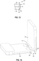
- FIG. 12 shows the hinge 400 moving from the open position toward the closed position in a second rotational direction 442.
- the first bearing 436 is a one-way bearing that provides a different resistance in the second rotational direction 442 from the first rotational direction (e.g., the first rotational direction 440 described in relation to FIG. 9 ).
- the first rotational resistance of the first pivot point 406 in the second rotational direction 442 is less than the second rotational resistance of the second pivot point 408 in the second rotational direction 442.
- the hinge 400 therefore, rotates around the first pivot point 406 before rotating around the second pivot point 408 when moving in the second rotational direction 442.
- the first body 402 rotates around the first pivot point 406 until reaching a closed first pivot point angle 412.
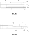
- the first rotational resistance then increases (either by contact between the first body 402 and the link 410 or by a restriction in the first bearing 436), and the rotation of the hinge 400 (e.g., rotation of the link 410 relative to the second body 404) continues around the second pivot point 408 to the clamshell closed position illustrated in FIG. 13 .
- the first pivot point 406 includes a one-way first bearing 436 that provides a first rotational resistance that changes with rotational direction
- the second pivot point 408 includes a second bearing 438 that provides a constant rotational resistance irrespective of rotational direction.
- the first pivot point 406 includes a one-way first bearing 436 that provides a first rotational resistance that changes with rotational direction
- the second pivot point 408 includes a one-way second bearing 438 that provides a second rotational resistance that changes with rotational direction.
- the first rotational resistance is greater than the second rotational resistance in the first rotational direction and the first rotational resistance is less than the second rotational resistance in the second rotational direction.
- the active pivot point is the second pivot point 408, and when the hinge 400 is positioned with the first body 402 and the second body 404 at an angle between 90° and 180°, the active pivot point is the first pivot point 406.
- a hinge behaves differently depending on a state of the first body.
- the hinge may have a different range of motion when the first body is connected to the hinge.
- the first pivot point has a first range of motion when a third body is connected to the first body and a different second range of motion with a third body is disconnected from or moved relative to the first body.
- FIG. 14 illustrates an embodiment of another electronic device with a hinge 500 connected to a first body 502 and a second body 504.
- the first body 502 supports a third body 544.
- the first body 502 functions as a stand for the third body 544.
- the first body 502 provides electrical and/or data communication between the second body 504 and the third body 544.
- the first body 502 supports the third body 544 while the third body 544 and second body 504 communicate through a wireless data communication.
- the third body 544 may include a processor in communication with a first wireless communication device
- the second body 504 may include a hardware storage device in communication with a second wireless communication device.
- the processor of the third body 544 may access the information stored on the hardware storage device of the second body 504 through the first and second wireless communication devices.
- the first body 502 supports the third body 544 in the depicted "laptop configuration" with the link 510 in line with the second body 504.
- the first pivot point 506 rotates to the 90° orientation illustrated (between the first body 502 and the link 510), stops, and rotation about the second pivot point 508 raises the link 510 to a 90° configuration with the second body 504.
- the link 510 then provides displacement of the first body 502 and second body 504 in the z-direction to enter the clamshell configuration illustrated in FIG. 15 .
- the third body 544 contacts the second body in the laptop configuration.
- the contact between the third body 544 and the second body 504 provides a physical hardstop on the rotational range of motion of the first pivot point 506 and forces any further rotation to be around the second pivot point 508.
- the presence of the third body 544 in the laptop configuration with the first body 502 actuates a locking mechanism in the hinge 500 to limit the rotational range of motion of the first pivot point 506 and forces any further rotation to be around the second pivot point 508.
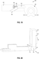
- FIG. 16 is a side view of the electronic device of FIG. 14 and 15 in a second closed configuration.
- the hinge 500 has a second stable closed configuration in a "nested configuration" of the hinge 500 where the link 510 remains in line with (e.g., at a 180° orientation from) the second body 504.
- the link 510 being in line with the second body 504 does not provide the displacement described in relation to FIG. 15 in the clamshell configuration.
- the nested configuration allows the first body 502 to nest against the second body 504, with a surface of the first body 502 sitting flush against a surface of the second body 504.
- the first pivot point 506 rotates to a 0° orientation (e.g., rotates and closes beyond the 90° orientation described in relation to FIG. 15 ) between the first body 502 and second body 504.
- the third body 544 is repositioned on a back surface 546 of the first body 502, providing a tablet configuration for the electronic device.
- the hinge 500 When the third body 544 is in the laptop configuration (illustrated and described in relation to FIG. 14 ), the hinge 500 has a first stable closure mode where each of the pivot points 506, 508 are active during the closure to the clamshell configuration. When the third body 544 is not in the laptop configuration (e.g., removed from the first body 502 and/or repositioned to a different location on the first body 502 as illustrated and described in relation to FIG. 16 ) the hinge 500 has a second stable closure mode where the first pivot point 506 only is active, and the first pivot point 506 has a larger range of motion.
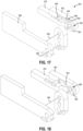
- FIG. 17 through FIG. 21 provide various exemplary embodiments of mechanisms to limit the rotation of the first pivot point and transition the hinge between a first stable closure mode and a second stable closure mode.
- FIG. 17 is a perspective view of an embodiment of a hinge 600 including a locking mechanism 648.
- a first pivot point 606 includes a locking mechanism 648.
- a second pivot point 608 includes a locking mechanism 648.
- both the first pivot point 606 and the second pivot point 608 include locking mechanisms 648.
- the embodiment illustrated in FIG. 17 includes a locking mechanism 648 on the first pivot point 606 that selectively limits the rotational range of motion of the first pivot point 606 (e.g., the rotation of the first body 602 relative to the link 610).
- the hinge 600 includes an arcuate track 650 positioned in the first body 602 that engages with the link 610 to determine the rotational range of motion of the first body 602 relative to the link 610 in the hinge 600.
- the track 650 terminates in endwalls 652 at either end of the track 650 around the first pivot point 606.
- the track 650 is positioned at least 135° around the first pivot point 606.
- the track 650 is positioned at least 180° around the first pivot point 606.
- the track 650 is positioned at least 225° around the first pivot point 606.
- the track 650 is positioned at least 270° around the first pivot point 606.
- the first body 602 is rotatable around the first pivot point 606 relative to the link 610 until a portion of the link 610 contacts the endwall 652 of the track 650 preventing further rotation of the first body 602.
- the locking mechanism 648 includes a pin 654 that is moveable relative to the first body 602 to selectively enter the track 650.
- the pin 654 limits the rotational range of motion of the first body 602 relative to the link 610 by effectively shortening with the track 650.
- a pin end 656 can interfere with the motion of a portion of the link 610 relative to the first body 602.
- the pin 654 limits the rotational range of motion of the first body 602 relative to the link 610 to 45°. In other embodiments, when the pin 654 is inserted into the track 650, the pin 654 limits the rotational range of motion of the first body 602 relative to the link 610 to 60°. In yet other embodiments, when the pin 654 is inserted into the track 650, the pin 654 limits the rotational range of motion of the first body 602 relative to the link 610 to 90°. In at least one example, the first pivot point 606 has a rotational range of motion when the pin is retracted (e.g., not in the track 650) of 135° and a rotational range of motion of 45° when the pin is inserted.
- the pin 654 is movable relative to the first body 602 based upon the location and/or position of the third body 644 relative to the first body 602. For example, when the third body 644 is positioned in the laptop configuration, as shown in FIG. 17 (and as described in relation to FIG. 14 and 15 ), the third body 644 physically contacts a mechanical linkage 658 of the first body 602 that applies a force to the pin 654 to move the pin 654 into the track 650. Therefore, when the third body 644 is positioned in the laptop configuration, the rotational range of motion of the hinge 600 around the first pivot point 606 is limited and causes the closure of the first body to rotate the link 610 around the second pivot point 608.
- the third body 644 when the third body 644 is not in the laptop configuration relative to the first body 602 (e.g., removed to be used as a tablet or rotated away from the second body to be nested in the tablet configuration described in relation to FIG. 16 ), the force on the linkage 658 is removed and the pin 654 is free to move toward a retracted position away from the track 650.
- the rotational range of motion of the first pivot point 606 is limited by the endwalls 652 of the track 650 and not by contact with the pin 654.
- FIG. 19 is a side view of the first body 602 of FIG. 18 with the pin 654 in the retracted position.
- the pin 654 is biased toward the retracted position.
- FIG. 19 illustrates a magnet 660 positioned on the opposite side of the pin 654 from the track 650.
- the pin 654 may include a magnetic or ferromagnetic material such that the magnet 660 applies an attractive force 662 to the pin 654 to bias the pin 654 toward the magnet 660.
- the mechanical linkage 658 or other mechanism removes a countering force from the pin 654, the attractive force 662 may move the pin 654.
- a magnet is positioned in the third body to apply a force to the pin 654 to move the pin when the third body is in the laptop configuration.
- the pin 654 is biased toward the retracted position by other biasing mechanisms.
- the biasing mechanism may be an elastically deformable member coupled to the pin 654 (or an elastically deformable portion of the pin 654) and the first body 602 that pulls the pin 654 toward the retracted position.
- the biasing mechanism is a spring such as a coil spring or a leaf spring.
- the biasing mechanism is an elastic polymer.
- the biasing mechanism is a combination of such elements, such as a coil spring and a magnet.
- the hinge 600 may lack a biasing element that passively biases the pin 654 toward the retracted position and, rather (or additionally) includes an actuatable movement device that is actuated by the position of the third body.
- the pin 654 may be movable between the retracted position and the inserted position (i.e., inserted into the track 650) by electromagnetic actuation.
- the magnet 660 may be an electromagnet that selectively applies an attractive force 662 or an opposing repulsive force to move the pin 654.
- the electromagnet applies a repulsive force to move the pin 654 into the track 650, limiting the rotational range of motion of the first body 602.
- the electromagnet applies an attractive force 662, allowing the larger rotational range of motion between the endwalls 652 of the track 650.
- the actuatable movement device that moves the pin 654 is an electric motor.
- the electric motor may be a linear actuator motor.
- the electric motor may be a screw motor.
- an actuatable movement device is actuated by other devices.
- an actuatable movement device is in data communication with a pressure switch.
- the pressure switch may detect the presence or position of the third body relative to the first body 602 to selectively actuate the actuatable movement device when the third body is in the laptop configuration, the tablet configuration, or other position.
- the actuatable movement device is actuated by a computerized control.
- the actuatable movement device can be in data communication with a processor in the first body, second body, or third body, that allows the actuatable movement device to be selectively actuated through software and/or firmware of an electronic device.
- a hinge 700 includes a mechanical hardstop 764 on the third body 744 and/or the link 710 to limit the rotational range of motion around the first pivot point 706 when the third body 744 is in a laptop configuration.
- the hardstop on the third body 744 and/or the link 710 does not contact and limit the rotational range of motion, allowing a larger rotational range of motion around the first pivot point 706.
- first body 702 and third body 744 are rotatably coupled to one another with a polymeric flap 766.
- the polymeric flap 766 allows the third body 744 to hinge relative to the first body 702 and flip to a back surface 746 of the first body 702.
- the first body 702 and third body 744 are rotatably coupled by a hinge, such as a piano hinge.
- FIG. 20 illustrates an embodiment of a hinge 700 with a hardstop 764 positioned on the link 710.
- the hardstop 764 contacts the third body 744 when the third body 744 is in the laptop configuration (illustrated in FIG. 20 ) and when the first body 702 is positioned at a 90° angle relative to the link 710.
- the third body 744 is rotated around the polymeric flap 766 toward the back surface 746 of the first body 702
- the first body 702 can rotate beyond a 90° orientation relative to the link 710 and approach a 0° orientation relative to the link 710.
- FIG. 21 illustrates an embodiment of a hinge 800 with a hardstop 864 positioned on the third body 844.
- the hardstop 864 contacts the link 810 when the third body 844 is in the laptop configuration (illustrated in FIG. 21 ) and when the first body 802 is positioned at a 90° angle relative to the link 810.
- the third body 844 is rotated around the polymeric flap 866, the first body 802 can rotate beyond a 90° orientation relative to the link 810 and approach a 0° orientation relative to the link 810 (such as illustrated in FIG. 16 ) and lie in plane with the second body 806.
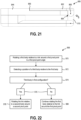
- FIG. 22 is a flowchart illustrating a method 968 of moving a hinge between an open configuration and a plurality of closed configurations.
- the hinge has a plurality of pivot points, which can each be active at different times and/or positions within the rotation of the hinge.
- the hinge has a first body and a second body that are rotatable about a first pivot point and a second pivot point, respectively.
- the first body and the second body are connected by a link positioned therebetween, where the first body is rotatable relative to the link around the first pivot point and the second body is rotatable relative to the link around the second pivot point.
- the method 968 includes rotating the first body relative to the link around the first pivot point to a first pivot point angle between the first body and the link at 970.
- the first pivot point angle may be 90°.
- the first pivot point is active while rotating the first body relative to the second body, and the second pivot point is inactive.
- the inactive second pivot point is locked by a follower or other locking mechanism that mechanically interferes with the rotation of the link and second body relative to one another (such as described in relation to FIG. 5 through FIG. 8 ).
- the first pivot point has a first rotational resistance and the second pivot point has a second rotational resistance, where the second rotational resistance is greater than the first rotational resistance.
- a force applied to move the first body relative to the second body will, due to the difference is rotational resistances, preferentially rotate the hinge around the first pivot point relative to the second pivot point (such as described in relation to FIG. 9 through FIG. 13 ).
- the method 968 further includes detecting a position of a third body relative to the first body at 972.
- detecting the position of the third body includes contacting a portion of a locking mechanism of the first body with the third body (such as described in relation to FIG. 17 and FIG. 18 ).
- detecting the position of the third body includes contacting a pressure switch of the first body with the third body.
- detecting the position of the third body includes reading an electronic file with a microprocessor in data communication with the locking mechanism.
- detecting the position of the third body includes contacting a portion of the link with the third body.
- the link has a hardstop that selectively engages the third body (such as described in relation to FIG. 20 ).
- the third body has a hardstop that selectively engages the link (such as described in relation to FIG. 21 ).
- the method 968 further includes checking whether the third body is in a first configuration at 974 after detecting the position of the third body relative the first body at 972.
- the first configuration is a laptop configuration of an electronic device.
- the third body can include a display and the second body can include a keyboard or other human interface device.
- the display When the display is positioned on the first body such that the display is oriented toward the keyboard (such as illustrated in FIG. 1 ), the first body may be in a laptop configuration.
- the third body may be disconnected from the first body (such as described in relation to FIG. 18 ) or repositioned on the first body at a different orientation or location (such as described in relation to FIG. 16 ).
- the first configuration is another configuration of the first body and the third body.
- the hinge may continue rotating the first body toward the second body in one of a plurality of rotational modes.
- the decision outcome confirms the third body is in the first configuration (e.g., "yes” in the decision outcome at 976)
- the first pivot point becomes inactive and the hinge begins rotating the link relative to the second body around the second pivot point at 978 (such as described in relation to FIG. 12 and FIG. 13 ).
- the decision outcome does not confirm the third body is in the first configuration (e.g., "no" in the decision outcome at 976)
- the first pivot point remains active and the hinge continues rotating the first body relative to the link around the first pivot point at 980 (such as described in relation to FIG. 12 and FIG. 13 ).
- the first pivot point remains active with a larger rotational range of motion than the "yes" decision outcome.
- a hinge has a plurality of stable positions that are achieved through different active pivot points during the rotation of the hinge.
- the hinge allows an electronic device or other device to arrange a first body and a second body of the device differently depending on how the hinge opens and closes.
- the hinge can allow multiple operational modes of the device by positioning the first body and second body relative to one another depending on the configuration of a third body relative to the first body.
- Numbers, percentages, ratios, or other values stated herein are intended to include that value, and also other values that are “about” or “approximately” the stated value, as would be appreciated by one of ordinary skill in the art encompassed by embodiments of the present disclosure.
- a stated value should therefore be interpreted broadly enough to encompass values that are at least close enough to the stated value to perform a desired function or achieve a desired result.
- the stated values include at least the variation to be expected in a suitable manufacturing or production process, and may include values that are within 5%, within 1%, within 0.1%, or within 0.01% of a stated value.
- any directions or reference frames in the preceding description are merely relative directions or movements.
- any references to “front” and “back” or “top” and “bottom” or “left” and “right” are merely descriptive of the relative position or movement of the related elements.
Landscapes
- Engineering & Computer Science (AREA)
- Computer Hardware Design (AREA)
- Theoretical Computer Science (AREA)
- Physics & Mathematics (AREA)
- Human Computer Interaction (AREA)
- General Engineering & Computer Science (AREA)
- General Physics & Mathematics (AREA)
- Mathematical Physics (AREA)
- Signal Processing (AREA)
- Pivots And Pivotal Connections (AREA)
- Casings For Electric Apparatus (AREA)
- Telephone Set Structure (AREA)
Claims (15)
- Scharniersystem (100, 200, 300, 400, 500, 600, 700, 800) für eine bistabile Bewegung, wobei das Scharniersystem umfasst: einen ersten Körper (102, 202, 302, 402, 502, 602, 702); einen zweiten Körper (104, 204, 304, 404, 504, 806); ein Verbindungselement (110, 210, 410, 510, 610, 710), wobei das Verbindungselement relativ zu dem ersten Körper um einen ersten Drehpunkt (106, 206, 306, 406, 506, 606, 706) drehbar ist und relativ zu dem zweiten Körper um einen zweiten Drehpunkt (108, 208, 308, 408, 508, 608) drehbar ist, wobei der erste Drehpunkt einen ersten Drehwiderstand aufweist und der zweite Drehpunkt einen zweiten Drehwiderstand aufweist, der sich von dem ersten Drehwiderstand unterscheidet;dadurch gekennzeichnet, dass es einen dritten Körper (544, 744) umfasst, der selektiv relativ zu dem ersten Körper (502) in einer ersten Konfiguration positionierbar ist, wobei der dritte Körper einen ersten Drehbewegungsbereich um den ersten Drehpunkt (506, 606) einschränkt, wenn er in der ersten Konfiguration positioniert ist;wobei in der ersten Konfiguration der erste Körper (502) als Ständer fungiert, der den dritten Körper (544) stützt.
- Scharniersystem nach Anspruch 1, ferner umfassend: eine Verriegelung, wobei die Verriegelung Folgendes beinhaltet: ein Verbindungselement, das zwischen dem ersten Körper und dem zweiten Körper angeordnet ist; einen ersten Nocken (320), der mit dem ersten Körper (302) verbunden ist und eine erste Nockenfläche (324) aufweist, wobei der erste Nocken um den ersten Drehpunkt (306) drehbar ist; einen zweiten Nocken (322), der mit dem zweiten Körper (304) verbunden ist und eine zweite Nockenfläche (328) aufweist, wobei der zweite Nocken (322) um den zweiten Drehpunkt (308) drehbar ist; und einen relativ zu dem ersten Nocken und dem zweiten Nocken beweglichen Nachläufer (318), wobei der Nachläufer so konfiguriert ist, dass er von der ersten Nockenfläche und der zweiten Nockenfläche aufgenommen wird.
- Scharniersystem (400) nach Anspruch 1, ferner umfassend ein Einrichtungslager (436) am ersten Drehpunkt (406), das einen ersten Drehwiderstand um den ersten Drehpunkt (406) in einer ersten Drehrichtung (440) und einen dritten Drehwiderstand um den ersten Drehpunkt (406) in einer zweiten Drehrichtung (442) bereitstellt, wobei sich der erste Drehwiderstand von dem dritten Drehwiderstand unterscheidet.
- Scharniersystem nach Anspruch 3, wobei der erste Drehwiderstand kleiner als der zweite Drehwiderstand ist und der zweite Drehwiderstand kleiner als der dritte Drehwiderstand ist.
- Scharniersystem nach Anspruch 1, wobei der erste Körper einen Verriegelungsmechanismus (648) mit einem Stift (654) beinhaltet, der zwischen einer eingeführten Position und einer zurückgezogenen Position beweglich ist, wobei die eingeführte Position den ersten Drehbewegungsbereich des Verbindungselements und des ersten Körpers um den ersten Drehpunkt begrenzt.
- Scharniersystem nach Anspruch 5, wobei sich der Stift in der eingeführten Position befindet, wenn sich der dritte Körper in der ersten Konfiguration befindet.
- Scharniersystem nach Anspruch 5, wobei der Verriegelungsmechanismus ein mechanisches Gestänge (658) beinhaltet, das den Stift (654) bewegt, wenn der dritte Körper das mechanische Gestänge berührt.
- Scharniersystem nach Anspruch 5, wobei der Verriegelungsmechanismus einen Vorspannmechanismus beinhaltet, der den Stift in Richtung der zurückgezogenen Position vorspannt.
- Scharniersystem nach Anspruch 5, wobei der Verriegelungsmechanismus eine betätigbare Bewegungsvorrichtung beinhaltet, um selektiv eine Bewegung des Stifts zwischen der zurückgezogenen Position und der eingeführten Position zu betätigen.
- Scharniersystem nach Anspruch 1, ferner umfassend einen Festanschlag (764, 864) zwischen dem Verbindungselement (710, 810) und dem dritten Körper (744, 844), der den ersten Drehbewegungsbereich mechanisch begrenzt, wenn sich der dritte Körper (744) in der ersten Konfiguration befindet.
- Verfahren (968) zum Bereitstellen einer bistabilen Bewegung in einem Scharnier (500, 600), wobei das Verfahren Folgendes umfasst: Drehen (970) eines ersten Körpers (502) relativ zu einem Verbindungselement (510) um einen ersten Drehpunkt (506) bis zu einem ersten Drehpunktwinkel (212, 312) zwischen dem ersten Körper (502) und dem Verbindungselement (510); Erkennen (972) einer Position eines dritten Körpers (544) relativ zu dem ersten Körper (502); wenn der dritte Körper in einer ersten Konfiguration (974) relativ zum ersten Körper am ersten Drehpunktwinkel ist: Drehen (978) des Verbindungselements (510) relativ zu einem zweiten Körper (504) um einen zweiten Drehpunkt (508), wobei in der ersten Konfiguration der erste Körper (502) als ein Ständer fungiert, der den dritten Körper (544) stützt; und wenn der dritte Körper (544) sich nicht in der ersten Konfiguration am ersten Drehpunktwinkel befindet: Fortsetzen (980) des Drehens des ersten Körpers (502) relativ zu dem Verbindungselement (510) um den ersten Drehpunkt (506).
- Verfahren nach Anspruch 11, wobei der erste Drehpunktwinkel 90° beträgt.
- Verfahren nach Anspruch 11, wobei der erste Drehpunkt einen größeren Drehwiderstand aufweist als der zweite Drehpunkt.
- Verfahren nach Anspruch 11, wobei das Erkennen der Position des dritten Körpers relativ zu dem ersten Körper das Kontaktieren eines Abschnitts des Verbindungselements mit einem Abschnitt des dritten Körpers am ersten Drehpunktwinkel beinhaltet.
- Verfahren nach Anspruch 11, wobei das Erkennen der Position des dritten Körpers das Kontaktieren eines Abschnitts eines Verriegelungsmechanismus des ersten Körpers mit dem dritten Körper beinhaltet.
Applications Claiming Priority (1)
| Application Number | Priority Date | Filing Date | Title |
|---|---|---|---|
| PCT/US2020/024700 WO2021194485A1 (en) | 2020-03-25 | 2020-03-25 | Bistable hinge with determinant motion |
Publications (2)
| Publication Number | Publication Date |
|---|---|
| EP4128727A1 EP4128727A1 (de) | 2023-02-08 |
| EP4128727B1 true EP4128727B1 (de) | 2024-11-20 |
Family
ID=70293134
Family Applications (1)
| Application Number | Title | Priority Date | Filing Date |
|---|---|---|---|
| EP20719884.7A Active EP4128727B1 (de) | 2020-03-25 | 2020-03-25 | Bistabiles scharnier mit determinanter bewegung |
Country Status (3)
| Country | Link |
|---|---|
| EP (1) | EP4128727B1 (de) |
| CN (1) | CN115336240B (de) |
| WO (1) | WO2021194485A1 (de) |
Family Cites Families (10)
| Publication number | Priority date | Publication date | Assignee | Title |
|---|---|---|---|---|
| US5564163A (en) * | 1994-11-08 | 1996-10-15 | Cema Technologies, Inc. | Lockable hinge assembly |
| KR20100016961A (ko) * | 2008-08-05 | 2010-02-16 | (주)엘티엠에이피 | 이동통신단말기의 힌지조립체 |
| CN201301889Y (zh) * | 2008-12-04 | 2009-09-02 | 联福生科技股份有限公司 | 铰链装置的角度限位结构 |
| JP5704613B2 (ja) * | 2012-05-30 | 2015-04-22 | 株式会社ナチュラレーザ・ワン | 2軸ヒンジ |
| US9625954B2 (en) * | 2014-11-26 | 2017-04-18 | Microsoft Technology Licensing, Llc | Multi-pivot hinge |
| CN204553526U (zh) * | 2015-01-19 | 2015-08-12 | 杭州安费诺飞凤通信部品有限公司 | 一种开合扭力有差异的铰链机构和移动电子产品终端 |
| KR102388747B1 (ko) * | 2016-01-05 | 2022-04-21 | 삼성전자주식회사 | 힌지 모듈, 이를 포함하는 케이스 및 전자 장치 |
| US10126785B2 (en) * | 2016-08-11 | 2018-11-13 | Microsoft Technology Licensing, Llc | Cam lock hinge for determinant movement |
| US10437293B2 (en) * | 2016-09-23 | 2019-10-08 | Microsoft Technology Licensing, Llc | Multi-axis hinge |
| US10253804B2 (en) * | 2017-01-24 | 2019-04-09 | Microsoft Technology Licensing, Llc | Hinged device |
-
2020
- 2020-03-25 EP EP20719884.7A patent/EP4128727B1/de active Active
- 2020-03-25 WO PCT/US2020/024700 patent/WO2021194485A1/en not_active Ceased
- 2020-03-25 CN CN202080099087.6A patent/CN115336240B/zh active Active
Also Published As
| Publication number | Publication date |
|---|---|
| CN115336240A (zh) | 2022-11-11 |
| US20230123520A1 (en) | 2023-04-20 |
| WO2021194485A1 (en) | 2021-09-30 |
| EP4128727A1 (de) | 2023-02-08 |
| CN115336240B (zh) | 2025-04-11 |
Similar Documents
| Publication | Publication Date | Title |
|---|---|---|
| US10126785B2 (en) | Cam lock hinge for determinant movement | |
| US8064970B2 (en) | Hinge assemblies for mobile terminals | |
| US11079809B2 (en) | Electronic apparatus | |
| US9740245B2 (en) | Locking mechanism | |
| CN109871067B (zh) | 转轴模块与电子装置 | |
| US6831229B1 (en) | Hinge cover mechanism for folding casings with lift function | |
| CN103593016B (zh) | 可携式电脑 | |
| US9009919B1 (en) | Steady opening and closing double-axis hinge | |
| KR20050056147A (ko) | 개량된 힌지를 갖는 전자 장치 | |
| CN109564449B (zh) | 铰链装置、系统以及方法 | |
| WO2008136949A1 (en) | Electronic device adjustable display member | |
| CN103823518A (zh) | 信息设备和信息设备的连杆机构 | |
| JP2012142746A (ja) | 機器開閉機構および情報機器 | |
| EP2013682A1 (de) | Doppelachsen-scharnier zur verwendung in elektronischen einrichtungen | |
| EP4128727B1 (de) | Bistabiles scharnier mit determinanter bewegung | |
| US12554288B2 (en) | Bistable hinge with determinant motion | |
| CN1043208C (zh) | 具有双枢点铰链摩擦连接器的电子组件盒体 | |
| CN114815976A (zh) | 一种转轴组件、电子设备及其旋转方法 | |
| US11054862B2 (en) | Undocking assist mechanisms and methods of use | |
| CN116950986A (zh) | 铰链机构和电子设备 | |
| CN102340939B (zh) | 掀盖式电子装置结构 | |
| US20230034612A1 (en) | Hinge with translatable axis | |
| CN112214068A (zh) | 连动机构及电子装置 | |
| TWM665908U (zh) | 可改變收合間距的雙軸鉸鏈 | |
| WO2006129911A1 (en) | Hinge apparatus |
Legal Events
| Date | Code | Title | Description |
|---|---|---|---|
| STAA | Information on the status of an ep patent application or granted ep patent |
Free format text: STATUS: UNKNOWN |
|
| STAA | Information on the status of an ep patent application or granted ep patent |
Free format text: STATUS: THE INTERNATIONAL PUBLICATION HAS BEEN MADE |
|
| PUAI | Public reference made under article 153(3) epc to a published international application that has entered the european phase |
Free format text: ORIGINAL CODE: 0009012 |
|
| STAA | Information on the status of an ep patent application or granted ep patent |
Free format text: STATUS: REQUEST FOR EXAMINATION WAS MADE |
|
| 17P | Request for examination filed |
Effective date: 20220923 |
|
| AK | Designated contracting states |
Kind code of ref document: A1 Designated state(s): AL AT BE BG CH CY CZ DE DK EE ES FI FR GB GR HR HU IE IS IT LI LT LU LV MC MK MT NL NO PL PT RO RS SE SI SK SM TR |
|
| DAV | Request for validation of the european patent (deleted) | ||
| DAX | Request for extension of the european patent (deleted) | ||
| GRAP | Despatch of communication of intention to grant a patent |
Free format text: ORIGINAL CODE: EPIDOSNIGR1 |
|
| STAA | Information on the status of an ep patent application or granted ep patent |
Free format text: STATUS: GRANT OF PATENT IS INTENDED |
|
| INTG | Intention to grant announced |
Effective date: 20240618 |
|
| GRAS | Grant fee paid |
Free format text: ORIGINAL CODE: EPIDOSNIGR3 |
|
| GRAA | (expected) grant |
Free format text: ORIGINAL CODE: 0009210 |
|
| STAA | Information on the status of an ep patent application or granted ep patent |
Free format text: STATUS: THE PATENT HAS BEEN GRANTED |
|
| P01 | Opt-out of the competence of the unified patent court (upc) registered |
Free format text: CASE NUMBER: APP_54336/2024 Effective date: 20241002 |
|
| AK | Designated contracting states |
Kind code of ref document: B1 Designated state(s): AL AT BE BG CH CY CZ DE DK EE ES FI FR GB GR HR HU IE IS IT LI LT LU LV MC MK MT NL NO PL PT RO RS SE SI SK SM TR |
|
| REG | Reference to a national code |
Ref country code: GB Ref legal event code: FG4D |
|
| REG | Reference to a national code |
Ref country code: CH Ref legal event code: EP |
|
| REG | Reference to a national code |
Ref country code: DE Ref legal event code: R096 Ref document number: 602020041627 Country of ref document: DE |
|
| REG | Reference to a national code |
Ref country code: IE Ref legal event code: FG4D |
|
| REG | Reference to a national code |
Ref country code: LT Ref legal event code: MG9D |
|
| REG | Reference to a national code |
Ref country code: NL Ref legal event code: MP Effective date: 20241120 |
|
| PG25 | Lapsed in a contracting state [announced via postgrant information from national office to epo] |
Ref country code: HR Free format text: LAPSE BECAUSE OF FAILURE TO SUBMIT A TRANSLATION OF THE DESCRIPTION OR TO PAY THE FEE WITHIN THE PRESCRIBED TIME-LIMIT Effective date: 20241120 Ref country code: PT Free format text: LAPSE BECAUSE OF FAILURE TO SUBMIT A TRANSLATION OF THE DESCRIPTION OR TO PAY THE FEE WITHIN THE PRESCRIBED TIME-LIMIT Effective date: 20250320 Ref country code: IS Free format text: LAPSE BECAUSE OF FAILURE TO SUBMIT A TRANSLATION OF THE DESCRIPTION OR TO PAY THE FEE WITHIN THE PRESCRIBED TIME-LIMIT Effective date: 20250320 |
|
| PGFP | Annual fee paid to national office [announced via postgrant information from national office to epo] |
Ref country code: DE Payment date: 20250218 Year of fee payment: 6 |
|
| PG25 | Lapsed in a contracting state [announced via postgrant information from national office to epo] |
Ref country code: FI Free format text: LAPSE BECAUSE OF FAILURE TO SUBMIT A TRANSLATION OF THE DESCRIPTION OR TO PAY THE FEE WITHIN THE PRESCRIBED TIME-LIMIT Effective date: 20241120 Ref country code: NL Free format text: LAPSE BECAUSE OF FAILURE TO SUBMIT A TRANSLATION OF THE DESCRIPTION OR TO PAY THE FEE WITHIN THE PRESCRIBED TIME-LIMIT Effective date: 20241120 |
|
| REG | Reference to a national code |
Ref country code: AT Ref legal event code: MK05 Ref document number: 1744597 Country of ref document: AT Kind code of ref document: T Effective date: 20241120 |
|
| PG25 | Lapsed in a contracting state [announced via postgrant information from national office to epo] |
Ref country code: BG Free format text: LAPSE BECAUSE OF FAILURE TO SUBMIT A TRANSLATION OF THE DESCRIPTION OR TO PAY THE FEE WITHIN THE PRESCRIBED TIME-LIMIT Effective date: 20241120 |
|
| PG25 | Lapsed in a contracting state [announced via postgrant information from national office to epo] |
Ref country code: ES Free format text: LAPSE BECAUSE OF FAILURE TO SUBMIT A TRANSLATION OF THE DESCRIPTION OR TO PAY THE FEE WITHIN THE PRESCRIBED TIME-LIMIT Effective date: 20241120 |
|
| PG25 | Lapsed in a contracting state [announced via postgrant information from national office to epo] |
Ref country code: NO Free format text: LAPSE BECAUSE OF FAILURE TO SUBMIT A TRANSLATION OF THE DESCRIPTION OR TO PAY THE FEE WITHIN THE PRESCRIBED TIME-LIMIT Effective date: 20250220 |
|
| PG25 | Lapsed in a contracting state [announced via postgrant information from national office to epo] |
Ref country code: LV Free format text: LAPSE BECAUSE OF FAILURE TO SUBMIT A TRANSLATION OF THE DESCRIPTION OR TO PAY THE FEE WITHIN THE PRESCRIBED TIME-LIMIT Effective date: 20241120 Ref country code: AT Free format text: LAPSE BECAUSE OF FAILURE TO SUBMIT A TRANSLATION OF THE DESCRIPTION OR TO PAY THE FEE WITHIN THE PRESCRIBED TIME-LIMIT Effective date: 20241120 Ref country code: GR Free format text: LAPSE BECAUSE OF FAILURE TO SUBMIT A TRANSLATION OF THE DESCRIPTION OR TO PAY THE FEE WITHIN THE PRESCRIBED TIME-LIMIT Effective date: 20250221 |
|
| PG25 | Lapsed in a contracting state [announced via postgrant information from national office to epo] |
Ref country code: PL Free format text: LAPSE BECAUSE OF FAILURE TO SUBMIT A TRANSLATION OF THE DESCRIPTION OR TO PAY THE FEE WITHIN THE PRESCRIBED TIME-LIMIT Effective date: 20241120 |
|
| PGFP | Annual fee paid to national office [announced via postgrant information from national office to epo] |
Ref country code: GB Payment date: 20250221 Year of fee payment: 6 |
|
| PG25 | Lapsed in a contracting state [announced via postgrant information from national office to epo] |
Ref country code: RS Free format text: LAPSE BECAUSE OF FAILURE TO SUBMIT A TRANSLATION OF THE DESCRIPTION OR TO PAY THE FEE WITHIN THE PRESCRIBED TIME-LIMIT Effective date: 20250220 |
|
| PG25 | Lapsed in a contracting state [announced via postgrant information from national office to epo] |
Ref country code: SM Free format text: LAPSE BECAUSE OF FAILURE TO SUBMIT A TRANSLATION OF THE DESCRIPTION OR TO PAY THE FEE WITHIN THE PRESCRIBED TIME-LIMIT Effective date: 20241120 |
|
| PG25 | Lapsed in a contracting state [announced via postgrant information from national office to epo] |
Ref country code: DK Free format text: LAPSE BECAUSE OF FAILURE TO SUBMIT A TRANSLATION OF THE DESCRIPTION OR TO PAY THE FEE WITHIN THE PRESCRIBED TIME-LIMIT Effective date: 20241120 |
|
| PG25 | Lapsed in a contracting state [announced via postgrant information from national office to epo] |
Ref country code: EE Free format text: LAPSE BECAUSE OF FAILURE TO SUBMIT A TRANSLATION OF THE DESCRIPTION OR TO PAY THE FEE WITHIN THE PRESCRIBED TIME-LIMIT Effective date: 20241120 |
|
| PG25 | Lapsed in a contracting state [announced via postgrant information from national office to epo] |
Ref country code: RO Free format text: LAPSE BECAUSE OF FAILURE TO SUBMIT A TRANSLATION OF THE DESCRIPTION OR TO PAY THE FEE WITHIN THE PRESCRIBED TIME-LIMIT Effective date: 20241120 |
|
| PG25 | Lapsed in a contracting state [announced via postgrant information from national office to epo] |
Ref country code: SK Free format text: LAPSE BECAUSE OF FAILURE TO SUBMIT A TRANSLATION OF THE DESCRIPTION OR TO PAY THE FEE WITHIN THE PRESCRIBED TIME-LIMIT Effective date: 20241120 |
|
| PG25 | Lapsed in a contracting state [announced via postgrant information from national office to epo] |
Ref country code: CZ Free format text: LAPSE BECAUSE OF FAILURE TO SUBMIT A TRANSLATION OF THE DESCRIPTION OR TO PAY THE FEE WITHIN THE PRESCRIBED TIME-LIMIT Effective date: 20241120 |
|
| PG25 | Lapsed in a contracting state [announced via postgrant information from national office to epo] |
Ref country code: IT Free format text: LAPSE BECAUSE OF FAILURE TO SUBMIT A TRANSLATION OF THE DESCRIPTION OR TO PAY THE FEE WITHIN THE PRESCRIBED TIME-LIMIT Effective date: 20241120 |
|
| REG | Reference to a national code |
Ref country code: DE Ref legal event code: R097 Ref document number: 602020041627 Country of ref document: DE |
|
| PG25 | Lapsed in a contracting state [announced via postgrant information from national office to epo] |
Ref country code: SE Free format text: LAPSE BECAUSE OF FAILURE TO SUBMIT A TRANSLATION OF THE DESCRIPTION OR TO PAY THE FEE WITHIN THE PRESCRIBED TIME-LIMIT Effective date: 20241120 |
|
| PLBE | No opposition filed within time limit |
Free format text: ORIGINAL CODE: 0009261 |
|
| STAA | Information on the status of an ep patent application or granted ep patent |
Free format text: STATUS: NO OPPOSITION FILED WITHIN TIME LIMIT |
|
| PG25 | Lapsed in a contracting state [announced via postgrant information from national office to epo] |
Ref country code: MC Free format text: LAPSE BECAUSE OF FAILURE TO SUBMIT A TRANSLATION OF THE DESCRIPTION OR TO PAY THE FEE WITHIN THE PRESCRIBED TIME-LIMIT Effective date: 20241120 |
|
| 26N | No opposition filed |
Effective date: 20250821 |
|
| REG | Reference to a national code |
Ref country code: CH Ref legal event code: H13 Free format text: ST27 STATUS EVENT CODE: U-0-0-H10-H13 (AS PROVIDED BY THE NATIONAL OFFICE) Effective date: 20251023 |
|
| PG25 | Lapsed in a contracting state [announced via postgrant information from national office to epo] |
Ref country code: LU Free format text: LAPSE BECAUSE OF NON-PAYMENT OF DUE FEES Effective date: 20250325 |
|
| REG | Reference to a national code |
Ref country code: BE Ref legal event code: MM Effective date: 20250331 |
|
| PG25 | Lapsed in a contracting state [announced via postgrant information from national office to epo] |
Ref country code: FR Free format text: LAPSE BECAUSE OF NON-PAYMENT OF DUE FEES Effective date: 20250331 |
|
| PG25 | Lapsed in a contracting state [announced via postgrant information from national office to epo] |
Ref country code: BE Free format text: LAPSE BECAUSE OF NON-PAYMENT OF DUE FEES Effective date: 20250331 |
|
| PG25 | Lapsed in a contracting state [announced via postgrant information from national office to epo] |
Ref country code: CH Free format text: LAPSE BECAUSE OF NON-PAYMENT OF DUE FEES Effective date: 20250331 |
|
| PG25 | Lapsed in a contracting state [announced via postgrant information from national office to epo] |
Ref country code: IE Free format text: LAPSE BECAUSE OF NON-PAYMENT OF DUE FEES Effective date: 20250325 |