EP4128670B1 - Protokollumsetzer und automatisierungssystem - Google Patents
Protokollumsetzer und automatisierungssystem Download PDFInfo
- Publication number
- EP4128670B1 EP4128670B1 EP21727456.2A EP21727456A EP4128670B1 EP 4128670 B1 EP4128670 B1 EP 4128670B1 EP 21727456 A EP21727456 A EP 21727456A EP 4128670 B1 EP4128670 B1 EP 4128670B1
- Authority
- EP
- European Patent Office
- Prior art keywords
- safety
- ethercat
- network
- data
- messages
- Prior art date
- Legal status (The legal status is an assumption and is not a legal conclusion. Google has not performed a legal analysis and makes no representation as to the accuracy of the status listed.)
- Active
Links
Images




Classifications
-
- H—ELECTRICITY
- H04—ELECTRIC COMMUNICATION TECHNIQUE
- H04L—TRANSMISSION OF DIGITAL INFORMATION, e.g. TELEGRAPHIC COMMUNICATION
- H04L69/00—Network arrangements, protocols or services independent of the application payload and not provided for in the other groups of this subclass
- H04L69/08—Protocols for interworking; Protocol conversion
-
- H—ELECTRICITY
- H04—ELECTRIC COMMUNICATION TECHNIQUE
- H04L—TRANSMISSION OF DIGITAL INFORMATION, e.g. TELEGRAPHIC COMMUNICATION
- H04L12/00—Data switching networks
- H04L12/28—Data switching networks characterised by path configuration, e.g. LAN [Local Area Networks] or WAN [Wide Area Networks]
- H04L12/40—Bus networks
- H04L12/40169—Flexible bus arrangements
- H04L12/40176—Flexible bus arrangements involving redundancy
- H04L12/40189—Flexible bus arrangements involving redundancy by using a plurality of bus systems
-
- H—ELECTRICITY
- H04—ELECTRIC COMMUNICATION TECHNIQUE
- H04L—TRANSMISSION OF DIGITAL INFORMATION, e.g. TELEGRAPHIC COMMUNICATION
- H04L12/00—Data switching networks
- H04L12/28—Data switching networks characterised by path configuration, e.g. LAN [Local Area Networks] or WAN [Wide Area Networks]
- H04L12/40—Bus networks
- H04L12/40169—Flexible bus arrangements
- H04L12/40176—Flexible bus arrangements involving redundancy
- H04L12/40182—Flexible bus arrangements involving redundancy by using a plurality of communication lines
-
- H—ELECTRICITY
- H04—ELECTRIC COMMUNICATION TECHNIQUE
- H04L—TRANSMISSION OF DIGITAL INFORMATION, e.g. TELEGRAPHIC COMMUNICATION
- H04L12/00—Data switching networks
- H04L12/28—Data switching networks characterised by path configuration, e.g. LAN [Local Area Networks] or WAN [Wide Area Networks]
- H04L12/40—Bus networks
- H04L2012/4026—Bus for use in automation systems
Definitions
- the invention relates to a protocol converter and an automation system with such a protocol converter.
- a bus system hereinafter referred to as a fieldbus system, connects the field devices such as sensors and actuators with an automation device.
- the fieldbus protocol a standardized protocol, hereinafter referred to as the fieldbus protocol, is used for message transmission between the participants, which determines who (identifier) what (measured value, command) when (initiative ) on the fieldbus.
- Fieldbus systems are now an integral part of every production system. Depending on the manufacturer, different fieldbus technologies are favored, which differ in terms of the connection structure, bus access and the standardized fieldbus protocol. In many manufacturing plants, there is therefore a requirement to combine the various fieldbus technologies used into a common fieldbus solution. Such an integration is realized with the help of protocol converters, also referred to as gateways.
- Gateways can connect different, even heterogeneous, networks and enable routing across network boundaries.
- the gateway represents a common node that belongs to the networks to be connected and handles cross-network data traffic. Gateways perform protocol translation and convert incoming data when transitioning from one network to another network. Protocol data that is not supported by the target network can be omitted from the gateway and additional protocol data required for further transport can be added by the gateway.
- a safety-certified fieldbus protocol hereinafter referred to as a safety fieldbus protocol, is therefore used to transmit safety-relevant messages between safety-relevant communication participants in a fieldbus system.
- a safety fieldbus protocol generally referred to as a safety communication protocol when there is no reference to a fieldbus, enables secure message transmission on the fieldbus, even if there are any number of unsafe fieldbus devices in the transmission path between the two safety-relevant communication participants and the transmission path forms a so-called black channel.
- the standards EN ISO 13849-1 and IEC/EN 62061 specify the safety performance of automation systems required to reduce risk.
- the safety-certified field and automation devices which form the safety-relevant participants in the network and in which a safety fieldbus protocol is used, usually have at least two-channel hardware.
- single-channel hardware can also be used if the software has at least a two-channel structure.
- safety gateways with two-channel hardware or software are also implemented in addition to the conventional gateways.
- Two-channel hardware has increased hardware costs.
- Two-channel software requires a powerful microprocessor and sufficient memory.
- the DE 10 2014 110017 A1 discloses a protocol converter with the features of the preamble of claim 1. Further prior art is out DE199 28 517 A1 and EP 1701270 A1 known.
- the object of the invention is to provide a protocol converter for cross-network data traffic of security-relevant messages and a corresponding automation system, which can be implemented cost-effectively.
- a protocol converter for converting security-relevant messages between the first and the second network is provided between the first and the second network.
- the protocol converter has a single-channel interface device that enables message exchange with the first network and/or with the second network.
- a single-channel filter module device connected to the interface device determines messages with the first security communication protocol and messages with the second security communication protocol from messages received by the interface device.
- An at least two-channel security module connected to the filter module device then converts the messages determined by the filter module device with the first security communication protocol into messages with the second security communication protocol or the messages determined by the filter module device with the second Security communication protocol into messages with the first security communication protocol.
- the protocol converter for cross-network data traffic of safety-relevant messages in the automation system can essentially be implemented in a single channel. Only the safety-relevant routines are designed with at least two channels. This has the advantage that the hardware or software costs for a second channel can be largely saved.
- the single-channel interface device has a single-channel first interface that enables message exchange with the first network, which has the at least one first participant with the first security communication layer that processes the first security communication protocol, and a single-channel second interface that enables message exchange with the second Network enables, which has the at least second participant with the second security communication layer, which processes the second security communication protocol.
- the filter module device has a single-channel first filter module in order to determine messages with the first security communication protocol from messages received from the first interface, and a single-channel second filter module in order to detect messages with the to determine the second security communication protocol.
- the at least two-channel security module is connected to the first and the second filter module in order to convert messages determined by the first filter module with the first security communication protocol into messages with the second security communication protocol or to convert messages determined by the second filter module with the second security communication protocol Implement messages using the first security communication protocol.
- This design enables an integrated protocol conversion in which both a protocol conversion of non-security-relevant messages and of security-relevant messages can be implemented in a single protocol converter.
- the two-channel security module can have at least two parallel software function channels.
- a cost-effective microcontroller which requires comparatively little memory since only a few safety-relevant software functions have to be implemented in two channels, can then be used in the protocol converter.
- a single-channel operating function module connected to the filter module device and the security module can be provided in the protocol converter in order to cyclically call the filter module device and the security module. This design ensures stable functionality of the protocol converter.
- Fig. 1 shows an automation system with a security gateway between an EtherCAT network and a PROFINET network, the EtherCAT network having a participant with a security communication layer that processes an FSoE communication protocol, and the PROFINET network having a participant with a security communication layer, which processes a PROFIsafe communication protocol.
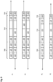
- Fig. 2 shows the schematic structure of the security gateway in the automation system Fig. 1 .
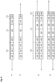
- Fig. 3 shows a sequence of transmission of a security-relevant message in the automation system Fig. 1 from the FSoE safety participant in the EtherCAT network to the PROFIsafe safety participant in the PROFINET network.
- Fig. 4 shows a sequence of transmission of a security-relevant message in the automation system Fig. 1 from the PROFIsafe safety participant in the PROFINET network to the FSoE safety participant in the EtherCAT network.
- Fig. 5 shows the schematic structure of a security gateway with an EtherCAT interface and an I/O-Link interface.
- Fig. 6 shows the schematic structure of a security gateway with an EtherCAT interface and a general hardware interface.
- networks are used to connect distributed field devices on a sensor/actuator level with a control level.
- the automation networks also called fieldbus systems, usually have a serial bus to which the network participants are connected.
- Manufacturers use various fieldbus concepts that differ in terms of the connection structure, bus access and the standardized fieldbus protocol, also referred to as the network protocol if there is no reference to a fieldbus.
- the network protocol determines how data exchange between participants in the network should be carried out.
- the network protocol determines the rules and formats for the communication behavior of the participants.
- the network protocol usually has a layered architecture, with the individual protocol layers being defined in the OSI reference model.
- the message structure determined by the network protocol contains all the information important for data exchange, such as sender and recipient, message type, message size and checksum to trace an error-free transmission. This information is prefixed to the payload in the message as a header or attached as a trailer.
- the possible network protocols can differ at various points.
- the network protocol can specify that communication can only take place in one direction or that communication in both directions is possible at the same time. Furthermore, the network protocol can determine that the communication is synchronized with a clock signal or should take place asynchronously.
- the network protocol can also determine the number of participants who are allowed to participate in the communication.
- the network protocol can also determine that a transmission should take place to only one recipient, a transmission to several recipients or even a message transmission to all participants.
- the network protocols can differ in terms of the position of the participants. If all participants have equal rights, there is symmetrical communication, otherwise there is asymmetrical communication. Network protocols also distinguish between synchronous communication, in which a response is waited after a request, and asynchronous communication, in which no response is required.
- the network protocol can carry out packet-oriented communication or can also be designed to be connection-oriented.
- the Ethernet protocol has established itself as a communication standard for short-range networks, especially automation networks.
- the Ethernet protocol defines the two lowest protocol layers, the physical layer and the data link layer.
- standard communication protocols such as the TCP/IP protocol can then be used for data transmission in the higher protocol layers.
- the Ethernet protocol divides the data to be transmitted into data packets, so-called frames, the structure of which is defined in the IEEE 802.3 standard.
- the actual Ethernet frame is preceded by a preamble and a start bit, the so-called Start Frame Delimiter SFD. This is then followed by the actual Ethernet data packet.
- the Ethernet data packet is composed of a header section, the header, a user data block and an end section, the trailer.
- the header starts with a 6-byte field for the destination address, which is followed by another 6-byte field with the source address.
- a further 4-byte field, the so-called VLAN tag, can then follow with additional control data in the header, which in particular contains prioritization information.
- the header ends with a 2-byte field, the so-called type field, which provides information about the protocol with which the data in the user data block is to be processed.
- the user data block following the header can have a length of 1500 bytes, although larger data blocks can also be permitted in various Ethernet protocol extensions.
- the user data block is terminated by a variable-length field, the so-called PAD field, which guarantees the specified minimum length of the Ethernet frame.
- the trailer which has a 4-byte field with a checksum, is connected to the user data block.
- a CRC calculation is performed over the bit string and the checksum is appended to the data block.
- the recipient performs the same calculation after receiving it. If the received checksum does not match the self-calculated checksum, the recipient assumes that the transmission was incorrect. The Ethernet frame is then discarded.
- Ethernet standard in industrial automation makes it possible to provide real-time solutions.
- Real-time capable fieldbus systems based on the Ethernet standard include PROFINET, EtherCAT, Powerlink or SERCOS III.
- the fieldbus protocol used is displayed in the type field in the header of the Ethernet frame.
- Ethernet In addition to the Ethernet standard, other fieldbus protocols such as CANopen, Interbus or Profibus can also be used in automation systems.
- Fieldbus systems are often operated as master-slave systems.
- the master participant in the fieldbus system is the controller that has bus access authorization and can output data to the fieldbus.
- the slave participants in the fieldbus system are the field devices, such as I/O devices, valves, drives, sensors, measuring transducers, etc. They do not have bus access authorization and are only allowed to acknowledge received data and transmit data when requested by the master participant.
- control via a fieldbus system is usually carried out in such a way that the master participant cyclically carries out control processes in order to generate output data for these and/or other slave participants based on input data from slave participants.
- the master participant After completing a control process cycle, the master participant sends the output data in the form of messages on the fieldbus, with the slave participants taking the output data assigned to the respective slave participant from the messages and using this output data to execute a local participant process.
- the data determined by the local participant process is then in turn transmitted from the slave participant to the master participant and then used by the master participant as input data for the next control process cycle.
- I/O-Link consists of an I/O-Link master participant and one or more I/O-Link slave participants, the sensors and actuators.
- the I/O-Link master participant provides the interface to the higher-level controller and controls communication with the connected I/O-Link field devices.
- a central requirement for automation systems is secure and reliable data transmission.
- To control and monitor technical processes within industrial automation it must be ensured that errors in the automation system are reliably detected. Therefore, additional security measures, so-called safety measures, are often implemented in the automation system, which ensure that errors are detected with a high degree of probability in order to minimize the risk of undetected errors.
- the safety measures intended to reduce risk in automation systems are described in the standards EN ISO 13849-1 and IEC/EN 62061.
- the safety measures required for the individual participants depend on the safety functions assigned to the respective participant.
- An essential safety measure is the redundant design of the participant in the form of two-channel hardware. Alternatively, single-channel hardware can also be used if the software then has a two-channel structure.
- a safety-certified communication protocol is still required for the transmission of safety-relevant messages between safety-relevant participants on the fieldbus.
- Automation systems are often used in mixed operation with safety-relevant participants and non-safety-relevant participants, whereby there are any number of unsafe fieldbus devices between the safety-relevant participants on the fieldbus.
- the security-certified communication protocols are usually designed in such a way that security-relevant messages can also be transmitted via a communication channel with unsecured properties, a so-called black channel.
- the safety protocol is then integrated between the safety-relevant participants and the "non-safe" fieldbus, which corresponds to the safety level of the safety-related automation system and detects and controls transmission errors on the fieldbus.
- the automation systems are made up of different, even heterogeneous, networks in which different communication protocols are used in the individual network areas, depending on the manufacturer.
- protocol converters also referred to as gateways, are used between the individual networks to establish the connection between the networks.
- the gateway is then a participant in the networks to be connected and handles cross-network data traffic.
- the gateway processes the forwarded messages by carrying out protocol conversion between the networks.
- the gateway can add or subtract log data as required.
- gateways are used as part of the transmission of security-relevant messages, the gateways must meet the corresponding security requirements. In order to implement security gateways cost-effectively, the required two-channel hardware or software design is reduced to the core area.
- the gateway then has an interface device that enables message exchange with the first network and with a second network.
- a single-channel filter module device is then connected to the interface device, which determines messages with a first security communication protocol and messages with a second security communication protocol from the messages received by the interface device.
- An at least two-channel security module in the gateway connected to the filter module device converts the messages determined by the filter module device with the first security communication protocol into messages with the second security communication protocol or converts messages with the second security communication protocol into messages with the first security communication protocol .
- cross-network data traffic including security-relevant messages
- the two-channel safety module can be implemented using at least two parallel software function channels. Through the gateway, a cost-effective microcontroller that requires comparatively little memory can then carry out the safety-relevant protocol implementation in two channels.
- the single-channel interface device can be a single-channel first interface, which enables message exchange with the first network, which has the at least one first participant with the first security communication layer processes the first security communication protocol, and a single-channel second interface that enables message exchange with the second network, which has the at least second participant with the second security communication layer that processes the second security communication protocol.
- the filter module device can have a single-channel first filter module to determine messages with the first security communication protocol from messages received from the first interface, and a single-channel second filter module to detect messages with the. from messages received from the second interface to determine the second security communication protocol.
- the at least two-channel security module is then connected to the first and second filter modules to convert messages determined by the first filter module with the first security communication protocol into messages with the second security communication protocol or to messages determined by the second filter module with the second security communication protocol into messages using the first security communication protocol.
- a single-channel operational function module is further connected to the first and second filter modules and the security module to cyclically call the first filter module, the second filter module and the security module.
- This design enables an integrated protocol conversion in which both a protocol conversion of non-security-relevant messages and of security-relevant messages can be implemented in a single protocol converter.
- Fig. 1 shows schematically the basic structure of an automation system with a first network 10 and a second network 20, which are connected to one another via a gateway, also referred to below as a protocol converter 30, which carries out an integrated protocol conversion.
- Each network has at least one master participant, which forms the control level, and at least one slave participant, which represents the sensor/actuator level.
- the master participant and the slave participant are connected to each other via a serial bus, via which the exchange of messages between the master participant and the slave participant takes place.
- the serial bus of the first network 10 is coupled to the serial bus of the second network 20 via the gateway.
- the data transmission in the first network 10 and in the second network 20 are each organized by the master participant in the form of data packets, with the Ethernet fieldbus protocol EtherCAT being used in the first network 10, for example, and the Ethernet fieldbus protocol PROFINET, for example, being used in the second network 20.
- the first network 10 is therefore referred to below as EtherCAT network 1 and the second network 20 as PROFINET network 2.
- the master participant in the EtherCAT network 1 is then an EtherCAT master 11 and the master participant in the second PPROFINET network is a PPROFINET master 21.
- the gateway that carries out the data exchange between the EtherCAT network 1 and the PPROFINET network 2 is an EtherCAT/PPROFINET gateway 3, which carries out a protocol conversion from the EtherCAT fieldbus protocol to the PROFINET fieldbus protocol and vice versa.
- the two fieldbus protocols EtherCAT and PROFINET used in the first and second networks 10, 20 are only examples. Alternatively, it is also possible to use a different fieldbus protocol based on the Ethernet standard, but also a non-Ethernet-based fieldbus protocol.
- both the slave participant in the EtherCAT network and the slave participant in the PPROFINET network are safety-relevant.
- the slave participant in the EtherCAT network 1 which is also referred to as the first participant 13, works with the safety variant Safety over EtherCAT, abbreviated FSoE, of EtherCAT and is an FSoE safety participant 12.
- the EtherCAT master 11 of the EtherCAT network 1 controls the message transmission, but usually does not carry out independent process data processing, which is why the safety communication protocol FSoE does not have to be implemented in the EtherCAT master 11.
- the PROFINET master 21 of the PROFINET network 2 then sets also uses the safety communication protocol PROFlsafe.
- both the safety communication protocol FSoE and the safety communication protocol PROFIsafe are installed on the EtherCAT/PPROFINET gateway 3 for protocol implementation between the EtherCAT network 1 and the PROFINET network 2.
- the EtherCAT/PPROFINET gateway 3 therefore represents a security gateway.
- any number of safety-relevant slave participants can also be provided on the respective fieldbus.
- non-safety-relevant participants are also integrated into the individual networks.
- the control level in the networks can also be divided among several master participants, depending on which fieldbus protocol is used.
- the exchange of messages between the EtherCAT network 1 and the PROFINET network 2 in Fig. 1 takes place in the following way:
- the FSoE safety participant 12 generates an FSoE message that is picked up by the EtherCAT master 11 and transmitted to the EtherCAT/PPROFINET gateway 3.
- the EtherCAT/PPROFINET gateway 3 the FSoE message is converted into a PROFIsafe message.
- the EtherCAT/PROFINET gateway 3 passes the PROFIsafe message to the PROFINET master 21, which sends the PROFIsafe message to the PROFIsafe safety participant 22, which interprets the PROFIsafe message.
- the PROFIsafe safety participant 22 sends a PROFIsafe message to the PROFINET master 21, which passes the PROFIsafe message to the EtherCAT/PROFIsafe gateway 3.
- the EtherCAT/PPROFINET gateway 3 converts the PROFIsafe message into an FSoE message.
- the FSoE message is then picked up by the EtherCAT master 11 and transmitted to the FSoE safety participant 21, which interprets the FSoE message.
- both the PROFINET master 21 and the slave participants FSoE safety participants 12 and PROFIsafe safety participants 22 have a safety communication layer for processing safety data.
- the security communication layer is usually designed with two channels in the form of hardware and/or software in accordance with the security requirements.
- Fig. 2 shows in detail the structure of the EtherCAT/PROFINET gateway 3, which works as a security gateway.
- the EtherCAT/PROFINET gateway 3 has a microcontroller 31 as the central unit.
- an EtherCAT slave controller 32 is provided as a single-channel first interface 42, which enables data exchange with the messages on the EtherCAT fieldbus 1.
- the EtherCAT slave controller 32 is connected to an EtherCAT memory 33, which forms the interface between the EtherCAT slave controller 32 and the microcontroller 31 and in which the interface between the EtherCAT slave controller 32 and the EtherCAT fieldbus 1 exchanged messages are stored.
- a PROFINET slave controller 34 is provided as a single-channel second interface 44, which carries out data exchange with the messages on the PROFINET fieldbus 2.
- the PROFINET slave controller 34 is connected to a PROFINET memory 35, which forms the interface between the PROFINET slave controller 34 and the microcontroller 31.
- the messages exchanged between the PROFINET slave controller 34 and the PROFINET fieldbus are stored in the PROFINET memory 35.
- a software module EtherCAT slave functions 311 is provided on the microcontroller 31, which is connected to the EtherCAT memory 33 and works, among other things, as a single-channel first filter module 321 in order to receive FSoE messages stored in the EtherCAT memory 33. detect messages.
- the EtherCAT slave functions software module 311 is further connected to an FSoE memory 312 in which the FSoE messages are stored.
- the FSoE memory 312 in turn has an interface to a software module safety functions 4, which forms a two-channel safety module.
- a software module PROFINET slave functions 313 is also provided on the microcontroller 31, which is connected to the PROFINET memory 35 and works, among other things, as a single-channel second filter module 323 in order to use PROFIsafe messages stored in the PROFINET memory 35 -Detect messages.
- the PROFINET slave functions software module 313 is further connected to a PROFIsafe memory 314 in which the PROFIsafe messages are stored.
- the PROFIsafe memory 314 also has an interface to the two-channel safety functions 4 software module.
- the safety module safety functions 4 can then detect changes to the FSoE messages or the PROFlsafe messages.
- the Safety Functions 4 software module is further designed to convert FSoE messages into PROFIsafe messages and PROFIsafe messages into FSoE messages.
- a single-channel operating function module 315 connected to the EtherCAT slave functions software module 311, the PROFINET slave functions software module 313 and the safety functions software module 4 is also provided on the microcontroller 31 in order to implement the software Cyclically call the EtherCAT slave functions module 311, the PROFINET slave functions software module 313 and the safety functions software module 4.
- the EtherCAT/PROFINET gateway 3 works as follows when converting an FSoE message into a PROFlsafe message:
- the FSoE message contained in an EtherCAT data packet is received via the EtherCAT network 1 by the EtherCAT slave controller 32 and written into the EtherCAT memory 33. From the EtherCAT memory 33, the FSoE message is transmitted from the single-channel software module EtherCAT slave functions 311 to the FSoE memory 312.
- the black channel in the EtherCAT/PROFINET gateway 3 extends to the FSoE memory 312.
- the two-channel safety module safety functions 4 can detect changes to the FSoE message that is stored in the FSoE memory 312.
- the two-channel safety functions software module 4 converts the FSoE message into the PROFIsafe message and stores it in the PROFIsafe memory 314.
- the single-channel software module PROFINET slave functions 313 copies the PROFIsafe message from the PROFIsafe memory 313 into the PROFINET memory 35.
- PROFINET slave controller 34 When a corresponding PROFINET data packet is received from the PROFINET slave controller 34, to the PROFINET memory 35, the PROFlsafe message is inserted into the PROFINET data packet from the PROFINET slave controller 34.
- the EtherCAT/PROFINET gateway 3 works as follows when converting a PROFlsafe message into an FSoE message:
- the PROFIsafe message contained in a PROFINET data packet is received by the PROFINET slave controller 34 and written into the PROFINET memory 35. From the PROFINET memory 35, the PROFIsafe message is transmitted from the single-channel software module PROFINET slave functions 313 to the PROFIsafe memory 314.
- the black channel of the EtherCAT/PROFINET gateway 3 still includes the PROFIsafe memory 314.
- the two-channel safety module safety functions 4 can then detect changes to the PROFIsafe message that is stored in the PROFIsafe memory 314.
- the two-channel software module safety functions 4 converts the PROFIsafe message into the FSoE message and stores the FSoE message in the FSoE memory 312.
- the single-channel software module EtherCAT slave functions 311 copies the FSoE message from the FSoE memory 312 into the EtherCAT memory 33.
- the FSoE message is inserted into the EtherCAT data packet by the EtherCAT controller 32.
- a software module operating function module 315 ensures that the two-channel software module safety functions 4 as well as the single-channel software module EtherCAT slave functions 311 and the single-channel software module PROFINET slave functions 313 to execute the above-explained Processes are called cyclically.
- the EtherCAT/PROFINET gateway 3 shown is designed in such a way that protocol conversion of EtherCAT messages and PPROFINET messages as well as PROFIsafe messages and FSoE messages is implemented.
- the security gateway that is in Fig. 3 is designed as a combined EtherCAT slave participant and PROFINET slave participant, it can then only be an EtherCAT slave participant or a PROFINET slave participant. Then only the software module EtherCAT slave functions and the EtherCAT slave controller are connected the EtherCAT network or the software module PROFINET functions and the PROFINET slave controller are intended for connection to the PROFINET network.
- the Safety Functions software module is further designed to convert FSoE messages into PROFIsafe messages and PROFIsafe messages into FSoE messages.
- a downstream EtherCAT/PROFINET gateway also carries out the conversion from the PROFINET data packet to the EtherCAT data packet if the safety gateway is designed exclusively as a PROFINET slave participant.
- the security gateway can in principle be designed as a participant in a freely selectable communication system, since both the FSoE protocol and the PROFIsafe protocol can transmit on any communication path. Then the software module EtherCAT slave functions 311 or the software module PROFINET slave functions 313 must be replaced by a corresponding software module, the EtherCAT slave controller 32 or the PROFINET slave controller 34 must be replaced by a corresponding controller serial interface or a dual-port RAM memory and the EtherCAT network 1 or the PROFINET network 2 can be replaced by a corresponding network or a corresponding fieldbus, a point-to-point connection or a data bus.
- Fig. 3 and Fig. 4 is a data transfer between the FSoE safety participant 12 and the PROFIsafe safety participant 22 in Fig. 1 shown automation network, where in Fig. 3 a transmission of FSoE data from the FSoE safety participant 12 to the PROFIsafe safety participant 22 and in Fig. 4 a transmission of PROFIsafe data from the PROFIsafe safety participant 22 to the FSoE safety participant 12 takes place.
- Ethernet data packets which, as explained above, consist of a header 700, a user data block 710 and a trailer 720 with the data packet checksum CRC.
- the destination address DA is in a destination address field 120
- the source address SA is in a source address field 125
- the source address is in a type field 130 EtherType included.
- the type field 130 specifies the Ethernet fieldbus protocol with which the data in the user data block is to be processed. For example, the EtherCAT protocol has the value 0x88A4 and the PROFINET protocol has the value 0x8892.
- the header contains both the destination address DA, i.e. in the destination address field 120, and the source address SA, i.e. in Source address field 125 no value used for addressing entered.
- the Ethernet data packets that are exchanged between the master participant and the slave participants are addressed, which is why a value is entered in the destination address field 120 for the destination address DA and in the source address field 130 for the source address SA in the header 700 is.
- the user data block 710 of the Ethernet data packets then has its own protocol header field 140 with control data of the fieldbus protocol used, i.e. either EtherCAT or PROFINET. This is followed by the actual user data area.
- each slave participant on the fieldbus has its own data block area in the user data area, which is part of a datagram.
- This data block area is also referred to below as a datagram field. Examples are in Fig. 3 and 4 a first datagram field 150 and a second datagram field 160 are shown.
- PROFINET protocol on the other hand, data in the user data area is intended for the fieldbus participant specified in the target address. Thus, for example, in Fig. 3 and 4 Only one user data field 155 is shown in each case.
- the user data block is completed by a trailer area end field 170 of the fieldbus protocol used, i.e. either EtherCAT end or PROFINET end.
- the respective data packet checksum CRC is then contained in a trailer field 180 in the trailer 720.
- the EtherCAT master 11 sends a first EtherCAT data packet E1 with two empty datagrams in the user data area to the two EtherCAT slave participants FSoE safety participant 12 and EtherCAT/PROFINET gateway 3. For reasons of For clarity, if the datagram is empty, the corresponding first and/or second datagram field 150, 160 is not displayed.
- the FSoE safety participant 12 enters the first data “FSoE message with FSoE data” as write data into the assigned first datagram field 150 of the first EtherCAT data packet E1. Since there is no write data yet in the EtherCAT/PROFINET gateway 3, the assigned second datagram field 160 of the first EtherCAT data packet E1 remains empty.
- the EtherCAT master 11 then receives the first EtherCAT data packet E1 again and copies the first data “FSoE message with FSoE data”.
- the EtherCAT master 11 then sends a second EtherCAT data packet E2 with the first data “FSoE message with FSoE data” as read data in the second datagram field 160 for the EtherCAT slave EtherCAT/PROFINET gateway 3.
- the EtherCAT slave controller 32 of the EtherCAT/PROFINET gateway 3 reads out the first data “FSoE message with FSoE data” from the assigned second datagram field 160 in the second EtherCAT data packet E2.
- the second datagram field 160 of the second EtherCAT data packet E2 assigned to the EtherCAT/PROFINET gateway 3 is then not described further and remains empty since there is still no write data in the EtherCAT/PROFINET gateway 3.
- the FSoE safety participant 12 enters second data "FSoE message with FSoE data" as write data into the assigned first datagram field 150 of the second EtherCAT data packet E2 when the second EtherCAT data packet E2 passes through.
- the second data "FSoE message with FSoE data” corresponds to the first data "FSoE message with FSoE data" as long as the FSoE safety participant 12 has not yet received a response and the FSoE safety participant 12 is therefore in Reaction to the answer has not yet generated any new data.
- the EtherCAT master 11 then receives the second EtherCAT data packet E2 with the second data “FSoE message with FSoE data”.
- the processing of the first data "FSoE message with FSoE data" in the in Fig. 2 The EtherCAT/PROFINET Gateway 3 shown is done in the following way: In the EtherCAT/PROFINET Gateway 3, the single-channel software module EtherCAT slave functions 311 copies the first data "FSoE message with FSoE data" from the EtherCAT memory 33 of the EtherCAT slave controller 32 into the FSoE memory 312 of the microcontroller 31.
- the two-channel software module safety functions 4 reads the first data “FSoE message with FSoE data” from the FSoE memory 312 and then converts it Data into first data “PROFIsafe message with FSoE data” and then saves the first data “PROFIsafe message with FSoE data” in the PROFIsafe memory 314 of the microcontroller 31.
- the single-channel software module PROFINET slave functions 313 reads the first data “PROFIsafe message with FSoE data” from the PROFIsafe memory 313 of the microcontroller 31 and places the first data “PROFIsafe message with FSoE data” in the PROFINET -Save 35 from.
- the PROFINET slave controller 34 sends the first data stored in the PROFINET memory 35 "PROFIsafe message with FSoE data" in a user data field 155 of a first PROFINET data packet P1 to the PROFINET master 21.
- the first PROFINET data packet P1 is specified in the header 700 in the destination address field 120 as the destination address DA of the PROFINET master 21 and in the source address field 125 as the source address SA of the EtherCAT/PROFINET gateway 3.
- the PROFINET master 21 receives the first PROFINET data packet P1, copies the first data "PROFIsafe message with FSoE data" and sends a second PROFINET data packet P2 to the PROFINET slave participant PROFlsafe safety participant 22.
- the second PROFINET data packet P2 is specified in the header 700 in the destination address field 120 as the destination address DA of the PROFIsafe safety participants 22 and in the source address field 125 as the source address SA of the PROFINET master 21.
- the PROFIsafe safety participant 22 After receiving the second PROFINET data packet P2, the PROFIsafe safety participant 22 then reads out the first data “PROFIsafe message with FSoE data” from the user data field 155.
- PROFI safe data are then transmitted from the PROFIsafe safety participant 22 to the FSoE safety participant 12 in response to the received FSoE data.
- the PROFINET slave participant PROFIsafe safety participant 22 sends a third PROFINET data packet P3 with the first data “PROFIsafe message with PROFIsafe data” in the user data field 155 to the PROFINET master 21.
- the PROFINET master 21 is specified in the header 700 in the destination address field 120 as the destination address DA of the PROFINET master 21 and in the source address field 125 as the source address SA of the PROFIsafe safety participant 22.
- the PROFINET master 21 receives the third PROFINET data packet P3 and copies the data “PROFIsafe message with PROFIsafe data” into the user data field 155 of a fourth PROFINET data packet P4.
- the PROFINET master 21 then sends the fourth PROFINET data packet P4 to the EtherCAT/PROFINET gateway 3.
- the EtherCAT/PROFINET gateway 3 is in the header 700 in the destination address field 120 as the destination address DA and in the source address field 125 is specified as the source address SA of the PROFINET master 21.
- the processing of the first data "PROFIsafe message with PROFIsafe data" in the in Fig. 2 The EtherCAT/PROFINET Gateway 3 shown is done in the following way:
- the PROFINET slave controller 34 of the EtherCAT/PROFINET gateway 3 stores the first data “PROFIsafe message with PROFIsafe data” from the fourth PROFINET data packet P4 in the PROFINET memory 35.
- the single-channel software module PROFINET slave functions 313 of the EtherCAT/PROFINET gateway 3 then transmits the first data “PROFIsafe message with PROFIsafe data” into the PROFIsafe memory 314 of the microcontroller 31.
- the two-channel software module safety functions 4 reads the first data “PROFIsafe message with PROFIsafe data” from the PROFIsafe memory 314, converts the first data “PROFIsafe message with PROFIsafe data” into the first data “FSoE message with PROFIsafe data” and then saves the first data "FSoE message with PROFIsafe data” in the FSoE memory 312 of the microcontroller 31. From there, the single-channel software module EtherCAT slave functions 311 reads the first data "FSoE message with PROFIsafe data” and writes the first data "FSoE message with PROFIsafe data” as write data into the EtherCAT memory 33 of the EtherCAT slave controller 32.
- the EtherCAT master 11 sends a third EtherCAT data packet E3 to the EtherCAT slave participants FSoE safety participant 12 and EtherCAT/PROFINET gateway 3.
- the datagram assigned to the FSoE safety participant 12 is empty, since there is no data for the FSoE safety participant 12 in the EtherCAT master 11.
- the EtherCAT master 11 has entered the second data “FSoE message with FSoE data” from the second EtherCAT data packet E2 as read data in the second datagram field 160.
- the second data “FSoE message with FSoE data” corresponds to the first data “FSoE message with FSoE data” as long as the FSoE safety participant 12 is still there has not received a response and the FSoE Safety participant 12 has therefore not yet generated any new data in response to the response.
- the EtherCAT slave controller 32 of the EtherCAT/PROFINET gateway 3 reads the second data “FSoE message with FSoE data” from the assigned second datagram field 160 in the third EtherCAT data packet E3.
- the EtherCAT slave controller 32 of the EtherCAT/PROFINET gateway 3 then enters the first data “FSoE message with PROFIsafe data” into the assigned second datagram field 160 of the third EtherCAT data packet E3.
- the second data “FSoE message with FSoE data” is processed in the EtherCAT/PROFINET Gateway 3 in the same way as the first data “FSoE message with FSoE data” to create second data “PROFISafe message with FSoE data ", which are then intended for the PROFINET slave participant PROFIsafe safety participant 22.
- the FSoE safety participant 12 When the third EtherCAT data packet E3 passes through, the FSoE safety participant 12 also enters third data "FSoE message with FSoE data" into the assigned first datagram field 150 of the third EtherCAT data packet E3.
- the third data "FSoE message with FSoE data” corresponds to the first or second data "FSoE message with FSoE data" as long as the FSoE safety participant 12 has not yet received a response and the FSoE safety participant 12 therefore has not yet created any new data in response to the response.
- the EtherCAT master 11 then receives the third EtherCAT data packet E3 in return.
- the EtherCAT master 11 copies the first data “FSoE message with PROFIsafe data” as read data for the EtherCAT slave participant FSoE safety participant 12 into the assigned first datagram field 150 of a fourth EtherCAT data package E4. Furthermore, the EtherCAT master 11 transmits the third data “FSoE message with FSoE data” from the third EtherCAT data packet E3 as read data into the second datagram field 160 for the EtherCAT slave participant EtherCAT/PROFINET gateway 3 in the fourth EtherCAT data package E4.
- the EtherCAT master 11 sends the fourth EtherCAT data packet E4 to the EtherCAT slave participants FSoE safety participant 12 and EtherCAT/PROFINET gateway 3.
- the EtherCAT slave participant FSoE safety participant 12 reads out the first data "FSoE message with PROFIsafe data" from the assigned first datagram field 150 of the fourth EtherCAT data package E4.
- the FSoE safety participant 12 then enters fourth data “FSoE message with FSoE data” into the assigned first datagram field 150 of the fourth EtherCAT data packet E4.
- the fourth data "FSoE message with FSoE data” corresponds to the first or second or third data "FSoE message with FSoE data" as long as the FSoE safety participant 12 has not yet received a response and the FSoE safety Participant 12 has therefore not yet generated any new data in response to the answer.
- the EtherCAT slave controller 32 of the EtherCAT/PROFINET gateway 3 reads out the third data “FSoE message with FSoE data” from the assigned second datagram field 160 in the fourth EtherCAT data packet E4 when the fourth EtherCAT data packet E4 passes through.
- the third data “FSoE message with FSoE data” is processed in the EtherCAT/PROFINET Gateway 3 in the same way as for the first data “FSoE message with FSoE data” to create third data “PROFISafe message with FSoE data ", which are then intended for the PROFINET slave participant PROFIsafe safety participant 22.
- the EtherCAT slave controller 32 of the EtherCAT/PROFINET gateway 3 After reading out the third data “FSoE message with FSoE data” from the assigned second datagram field 160 in the fourth EtherCAT data packet E4, the EtherCAT slave controller 32 of the EtherCAT/PROFINET gateway 3 carries second data “FSoE message with PROFIsafe -Data" into the assigned second datagram field 160 of the fourth EtherCAT data packet E4.
- the EtherCAT/PROFINET Gateway 3 has generated the second data "FSoE message with PROFIsafe data" from second data "PROFIsafe message with PROFIsafe data", which is combined with two further PROFINET data packets (not shown) in the same way as the first Data "PROFIsafe message with PROFIsafe data” was transferred from the PROFIsafe safety participant 22 via the PROFINET master 21 to the EtherCAT/PROFINET gateway 3.
- the EtherCAT master 11 then receives the fourth EtherCAT data packet E4 with the fourth data “FSoE message with FSoE data” and the second data “FSoE message with PROFIsafe data”.
- the data transmission between the FSoE safety participant 12 and the PROFIsafe safety participant 22 is then based on Fig. 3 and Fig. 4 continued in the manner explained.
- Fig. 5 shows an implementation of an EtherCAT/IO-Link gateway 300 with an FSoE/IO-Link safety protocol implementation.
- the components of the EtherCAT/IO-Link gateway 300, the components of the in Fig. 2 EtherCAT/PROFINET gateways 3 shown correspond to the same reference numbers and are not described again below.
- the EtherCAT/IO-Link gateway 300 is connected directly to an IO-Link network 200 with a single-channel software module IO-Link master functions 513 arranged on the microcontroller 31 as an interface in order to transmit messages with an IO-Link Replace safety slave participants (not shown).
- the single-channel software module IO-Link master functions 513 works, among other things, as a single-channel second filter module 323 in order to determine IO-Link safety messages from the messages received from the IO-Link slave participant.
- the IO-Link master functions software module 513 is further connected to an IO-Link safety memory 514, in which the IO-Link safety messages are stored.
- the IO-Link safety memory 514 also has an interface to the two-channel safety functions 4 software module.
- the Safety Functions 4 software module can then detect changes to the IO-Link safety messages.
- the Safety Functions 4 software module is also designed to convert FSoE messages into IO-Link Safety messages and IO-Link Safety messages into FSoE messages.
- the EtherCAT/IO-Link gateway 300 works as follows when converting an FSoE message into an IO-Link safety message: An FSoE message in an EtherCAT data packet is converted by the EtherCAT slave controller 32 into the EtherCAT Memory 33 is written, which forms the interface between the EtherCAT slave controller 32 and the microcontroller 31. From the EtherCAT memory 33, the FSoE message is transferred from the single-channel EtherCAT slave functions software module 311 to the FSoE memory 312, which forms the interface to the two-channel safety functions software module 4.
- the Black Channel extends up to the two-channel Safety Functions 4 software module, with the two-channel Safety Functions 4 safety module making changes the FSoE message recognizes.
- the two-channel safety functions software module 4 converts the FSoE message into an IO-Link safety message and stores the IO-Link safety message in the IO-Link safety memory 514, which is the interface between the two-channel Software module safety functions 4 and the single-channel software module IO-Link master functions 513.
- the single-channel software module IO-Link master functions 513 reads the IO-Link safety message from the IO-Link safety memory 514 and then sends the IO-Link safety message to the IO-Link safety message. Safety slave participant.
- an IO-Link safety message sent by the IO-Link safety slave participant is received by the single-channel software module IO-Link master functions 513 and copied into the IO-Link safety memory 514, which forms the interface to the two-channel software module safety functions 4.
- the Black Channel extends up to this point, with the two-channel safety module recognizing safety functions 4 changes to the IO-Link safety message.
- the two-channel safety functions software module 4 converts the IO-Link safety message into an FSoE message and stores the FSoE message in the FSoE memory 312, which is the interface between the two-channel safety functions software module 4 and the single-channel software module EtherCAT Slave Functions 311.
- the single-channel software module EtherCAT slave functions 311 copies the FSoE message from the FSoE memory 312 into the EtherCAT memory 33, which forms the interface between the EtherCAT slave controller 32 and the single-channel software module EtherCAT slave functions 311 .
- the FSoE message is included in the EtherCAT data packet from the EtherCAT slave controller 32 inserted in the run.
- the software module operating function module 315 provided on the microprocessor 31 ensures that the two-channel software module safety functions 4, the single-channel software module IO-Link master functions 513 and the single-channel EtherCAT slave functions module 311 are called cyclically.
- the EtherCAT/IO-Link gateway 300 is shown as an EtherCAT slave participant.
- the safety gateway could also be a participant in another fieldbus system because the FSoE protocol is not restricted to transmission on the EtherCAT fieldbus.
- Fig. 6 the construction of a safety gateway that carries out an implementation between the FSoE protocol and a safety hardware protocol.
- Fig. 2 EtherCAT/PROFINET gateways 3 shown correspond to the same reference numbers and are not described again below.
- the security gateway referred to below as EtherCAT/hardware gateway 301, is connected to hardware 201 with a single-channel software module standard functions 613 arranged on microcontroller 31 in order to exchange messages with a hardware participant (not shown).
- the interface of the software module standard functions 613 to the hardware 201 can be, for example, an IO port, a serial interface, a data bus or a field bus.
- the single-channel software module standard functions 613 works, among other things, as a single-channel second filter module 323 in order to determine safety messages from the messages received from the hardware participant.
- the software module standard functions 613 can also contain any other non-safety-relevant functions.
- the standard functions software module 613 is further connected to a safety memory 614 in which the safety messages are stored.
- the safety memory 614 also has an interface to the two-channel safety functions 4 software module.
- a black channel in the EtherCAT/hardware gateway 301 extends up to the Safety Functions 4 software module.
- the Safety Functions 4 software module can then detect changes to the safety messages.
- the Safety Functions 4 software module is designed to convert FSoE messages into safety messages and safety messages into FSoE messages.
- the safety functions software module 4 also has a hardware interface (not shown). It can also be provided that the safety functions software module executes any 4 software functions. The software functions can also be configurable in a similar way to safety logic, for example. The Safety Functions 4 software module can then process data received or sent via the hardware interface, from the other software modules in the gateway or via the FSoE message. Such a design of the safety functions software module 4 is also available in Fig. 2 and Fig. 5 Gateways shown possible.
- the EtherCAT/hardware gateway 301 works as follows when converting an FSoE message into a safety message: An FSoE message in an EtherCAT data packet is written by the EtherCAT slave controller 32 into the EtherCAT memory 33, which is the Interface between the EtherCAT slave controller 32 and the microcontroller 31 forms. From the EtherCAT memory 33, the FSoE message is transferred from the single-channel EtherCAT slave functions software module 311 to the FSoE memory 312, which forms the interface to the two-channel safety functions software module 4.
- the Black Channel extends up to the two-channel Safety Functions 4 software module, whereby the two-channel Safety Functions 4 safety module detects changes to the FSoE message.
- the two-channel safety functions 4 software module converts the FSoE message into a safety message and stores the safety message in the safety memory 614, which is the interface between the two-channel safety functions 4 software module and the single-channel Software module standard functions 613 forms.
- the single-channel software module standard functions 613 reads the safety message from the safety memory 614 and then sends the safety message to the hardware participant.
- a safety message sent by the hardware participant is received by the single-channel software module standard functions 613 and copied into the safety memory 614, which forms the interface to the two-channel software module safety functions 4.
- the Black Channel extends up to this point, with the two-channel safety module recognizing safety functions 4 changes to the safety message.
- the two-channel safety functions software module 4 converts the safety message into an FSoE message and stores the FSoE message in the FSoE memory 312, which is the interface between the two-channel safety functions software module 4 and the single-channel Software module EtherCAT slave functions 311 forms.
- the single-channel software module EtherCAT slave functions 311 copies the FSoE message from the FSoE memory 312 into the EtherCAT memory 33, which forms the interface between the EtherCAT slave controller 32 and the single-channel software module EtherCAT slave functions 311 .
- the FSoE message is incorporated into the EtherCAT data packet from the EtherCAT slave controller 32 in transit inserted.
- the software module operating function module 315 provided on the microprocessor 31 ensures that the two-channel software module Safety Functions 4, the single-channel software module Standard Functions 613 and the single-channel EtherCAT Slave Functions module 311 are called cyclically.
- the EtherCAT/hardware gateway 301 is shown as an EtherCAT slave participant. However, the safety gateway could also be a participant in another fieldbus system, since the FSoE protocol is not restricted to transmission on the EtherCAT fieldbus.
Landscapes
- Engineering & Computer Science (AREA)
- Computer Networks & Wireless Communication (AREA)
- Signal Processing (AREA)
- Computer Security & Cryptography (AREA)
- Data Exchanges In Wide-Area Networks (AREA)
- Communication Control (AREA)
Description
- Die Erfindung betrifft einen Protokollumsetzer und ein Automatisierungssystem mit einem solchen Protokollumsetzer.
- Diese Patentanmeldung beansprucht die Priorität der
deutschen Patentanmeldung 10 2020 113 572.6 . - Moderne Konzepte der Industrieautomation, d. h. der Steuerung und Überwachung von technischen Prozessen mit Hilfe von Software, beruhen auf der Idee einer zentralen Steuerung bei gleichzeitig verteilter Sensor-/Aktorebene. Ein Bussystem, im Weiteren als Feldbussystem bezeichnet, verbindet dabei die Feldgeräte wie Messfühler (Sensoren) und Stellglieder (Aktoren) mit einem Automatisierungsgerät.
- Damit die Teilnehmer am Feldbus ihre Nachrichten über dieselbe Leitung senden können, wird für die Nachrichtenübertragung zwischen den Teilnehmern ein normiertes Protokoll, im Weiteren als Feldbus-Protokoll bezeichnet, verwendet, das festlegt, wer (Kennung) was (Messwert, Befehl) wann (Initiative) auf dem Feldbus ausgibt.
- Feldbussysteme sind heute fester Bestandteil jeder Fertigungsanlage. Dabei werden je nach Hersteller verschiedene Feldbustechnologien favorisiert, die sich in Bezug auf die Verbindungsstruktur, den Buszugang und das normierte Feldbus-Protokoll unterscheiden. In vielen Fertigungsanlagen stellt sich deshalb die Anforderung, die verschiedenen eingesetzten Feldbustechnologien zu einer gemeinsamen Feldbuslösung zu verbinden. Eine solche Integration wird mit Hilfe von Protokollumsetzern, im Weiteren auch als Gateways bezeichnet, realisiert.
- Gateways können unterschiedliche, auch heterogene Netzwerke miteinander verbinden und ermöglichen ein Routing über Netzwerkgrenzen hinweg. Das Gateway stellt dabei einen gemeinsamen Knoten dar, der zu den zu verbindenden Netzwerken gehört und den netzübergreifenden Datenverkehr abwickelt. Gateways nehmen beim Übergang von einem Netzwerk zum anderen Netzwerk eine Protokollumsetzung vor und konvertieren eingehende Daten. Vom Zielnetzwerk nicht unterstützte Protokolldaten können dabei im Gateway wegfallen, zusätzliche für den Weitertransport nötige Protokolldaten vom Gateway ergänzt werden.
- Eine wesentliche Anforderung an ein Automatisierungssystem ist die Fehlersicherheit.
- Beim Steuern und Überwachen von technischen Prozessen muss sichergestellt sein, dass dann, wenn das Automatisierungssystem fehlerhaft arbeitet, daraus keine Gefahr für Mensch und Umwelt resultiert.
- Für eine Übertragung von sicherheitsrelevanten Nachrichten zwischen sicherheitsrelevanten Kommunikationsteilnehmern in einem Feldbussystem wird deshalb ein sicherheitszertifiziertes Feldbus-Protokoll, im Weiteren als Sicherheits-Feldbus-Protokoll bezeichnet, eingesetzt. Ein solches Sicherheits-Feldbus-Protokoll, allgemein, dann, wenn kein Bezug auf einen Feldbus gegeben ist, auch als Sicherheitskommunikationsprotokoll bezeichnet, ermöglicht eine sichere Nachrichtenübertragung auf dem Feldbus, auch dann, wenn sich zwischen den beiden sicherheitsrelevanten Kommunikationsteilnehmern im Übertragungsweg beliebig viele unsichere Feldbusgeräte befinden und der Übertragungsweg also einen sogenannten Black Channel bildet.
- Die Normen EN ISO 13849-1 und IEC/EN 62061 spezifizieren die zur Risikoreduzierung erforderliche sicherheitstechnische Leistungsfähigkeit von Automatisierungssystemen. Um die gewünschte sicherheitstechnische Leistungsfähigkeit zu erreichen, haben die sicherheitszertifizierte Feld- und Automatisierungsgeräte, die die sicherheitsrelevanten Teilnehmer im Netzwerk bilden und bei denen ein Sicherheits-Feldbus-Protokoll eingesetzt wird, in der Regel eine wenigstens zweikanalige Hardware. Alternativ kann auch einkanalige Hardware verwendet werden, wenn die Software wenigstens zweikanalig aufgebaut ist.
- Um eine Kommunikation zwischen sicherheitsrelevanten Teilnehmern in Netzwerken, die unterschiedliche Sicherheits-Feldbus-Protokolle unterstützen, zu ermöglichen, werden zusätzlich zu den herkömmlichen Gateways dann auch Sicherheits-Gateways mit zweikanaliger Hardware oder Software realisiert.
- Eine zweikanalige Hardware hat allerdings erhöhte Hardware-Kosten. Eine zweikanalige Software erfordert dagegen einen leistungsfähigen Mikroprozessor sowie ausreichend Speicher.
- Die
DE 10 2014 110017 A1 offenbart einen Protokollumsetzer mit den Merkmalen des Oberbegriffs des Anspruchs 1. Weiterer Stand der Technik ist ausDE199 28 517 A1 undEP 1701270 A1 bekannt. - Aufgabe der Erfindung ist es, einen Protokollumsetzer für einen netzwerkübergreifenden Datenverkehr von sicherheitsrelevanten Nachrichten und ein entsprechendes Automatisierungssystem bereitzustellen, die kostengünstig realisiert werden können.
- Diese Aufgabe wird mit einem Protokollumsetzer nach Anspruch 1 und einem Automatisierungssystem nach Anspruch 8 gelöst. Bevorzugte Weiterbildungen sind in den abhängigen Ansprüchen angegeben.
- In einem Automatisierungssystem mit einem ersten Netzwerk und einem zweiten Netzwerk, bei dem das erste und zweite Netzwerk unterschiedliche Netzwerkprotokolle zum Nachrichtenaustausch verwenden, und bei dem das erste Netzwerk wenigstens einen ersten Teilnehmer mit einer ersten Sicherheitskommunikationsschicht aufweist, die ein erstes Sicherheitskommunikationsprotokoll verarbeitet, und bei dem das zweite Netzwerk wenigstens einen zweiten Teilnehmer mit einer zweiten Sicherheitskommunikationsschicht aufweist, die ein zweites Sicherheitskommunikationsprotokoll verarbeitet, ist zwischen dem ersten und dem zweiten Netzwerk ein Protokollumsetzer zum Umsetzen von sicherheitsrelevanten Nachrichten zwischen dem ersten und dem zweiten Netzwerk vorgesehen. Der Protokollumsetzer weist eine einkanalige Schnittstellen-Einrichtung, die einen Nachrichtenaustausch mit dem ersten Netzwerk und/ oder mit dem zweiten Netzwerk ermöglicht, auf. Eine mit der Schnittstellen-Einrichtung verbundene einkanalige Filter-Modul-Einrichtung ermittelt aus von der Schnittstellen-Einrichtung empfangenen Nachrichten Nachrichten mit dem ersten Sicherheitskommunikationsprotokoll und Nachrichten mit dem zweiten Sicherheitskommunikationsprotokoll. Ein mit der Filter-Modul-Einrichtung verbundenes wenigstens zweikanaliges Sicherheits-Modul setzt dann die von der Filter-Modul-Einrichtung ermittelten Nachrichten mit dem ersten Sicherheitskommunikationsprotokoll in Nachrichten mit dem zweiten Sicherheitskommunikationsprotokoll beziehungsweise die von der Filter-Modul-Einrichtung ermittelten Nachrichten mit dem zweiten Sicherheitskommunikationsprotokoll in Nachrichten mit dem ersten Sicherheitskommunikationsprotokoll um.
- Der Protokollumsetzer für einen netzübergreifenden Datenverkehr von sicherheitsrelevanten Nachrichten im Automatisierungssystem kann im Wesentlichen einkanalig realisiert werden. Nur die sicherheitsrelevanten Routinen sind wenigstens zweikanalig ausgelegt. Das hat den Vorteil, dass die Hardware- beziehungsweise Softwarekosten für einen zweiten Kanal weitgehend eingespart werden können.
- Die einkanalige Schnittstellen-Einrichtung weist eine einkanalige erste Schnittstelle, die einen Nachrichtenaustausch mit dem ersten Netzwerk ermöglicht, das den wenigstens einen ersten Teilnehmer mit der ersten Sicherheitskommunikationsschicht aufweist, die das erste Sicherheitskommunikationsprotokoll verarbeitet, und eine einkanalige zweite Schnittstelle, die einen Nachrichtenaustausch mit dem zweiten Netzwerk ermöglicht, das den wenigstens zweiten Teilnehmer mit der zweiten Sicherheitskommunikationsschicht aufweist, die das zweite Sicherheitskommunikationsprotokoll verarbeiten, auf. Ferner weist die Filter-Modul-Einrichtung ein einkanaliges erstes Filter-Modul, um aus von der ersten Schnittstelle empfangenen Nachrichten Nachrichten mit dem ersten Sicherheitskommunikationsprotokoll zu ermitteln, und ein einkanaliges zweites Filter-Modul, um aus von der zweiten Schnittstelle empfangenen Nachrichten Nachrichten mit dem zweiten Sicherheitskommunikationsprotokoll zu ermitteln, auf. Das wenigstens zweikanalige Sicherheits-Modul ist mit dem ersten und dem zweiten Filter-Modul verbunden, um vom ersten Filter-Modul ermittelte Nachrichten mit dem ersten Sicherheitskommunikationsprotokoll in Nachrichten mit dem zweiten Sicherheitskommunikationsprotokoll beziehungsweise um vom zweiten Filter-Modul ermittelte Nachrichten mit dem zweiten Sicherheitskommunikationsprotokoll in Nachrichten mit dem ersten Sicherheitskommunikationsprotokoll umzusetzen.
- Diese Auslegung ermöglicht eine integrierte Protokollumsetzung, bei der sowohl eine Protokollumwandlung von nicht-sicherheitsrelevanten Nachrichten als auch von sicherheitsrelevanten Nachrichten in einem einzelnen Protokollumsetzer realisierbar ist.
- Das zweikanalige Sicherheits-Modul kann wenigstens zwei parallele Software-Funktionskanäle aufweisen. Im Protokollumsetzer kann dann ein kostengünstiger Mikrocontroller, der vergleichsweise wenig Speicher benötigt, da nur wenige sicherheitsrelevante Software-Funktionen zweikanalig realisiert werden müssen, eingesetzt werden.
- Im Protokollumsetzer kann ein mit der Filter-Modul-Einrichtung und dem Sicherheits-Modul verbundenes einkanaliges Betriebsfunktions-Modul vorgesehen sein, um die Filter-Modul-Einrichtung und das Sicherheits-Modul zyklisch aufzurufen. Diese Auslegung sorgt für eine stabile Funktionsweise des Protokollumsetzers.
- Nachfolgend wird die Erfindung anhand von Figuren näher erläutert.
-
Fig. 1 zeigt ein Automatisierungssystem mit einem Sicherheits-Gateway zwischen einem EtherCAT-Netzwerk und einem PROFINET-Netzwerk, wobei das EtherCAT-Netzwerk einen Teilnehmer mit einer Sicherheitskommunikationsschicht aufweist, die ein FSoE-Kommunikationsprotokoll verarbeitet, und das PROFINET-Netzwerk einen Teilnehmer mit einer Sicherheitskommunikationsschicht aufweist, die ein PROFIsafe-Kommunikationsprotokoll verarbeitet. -
Fig. 2 zeigt den schematischen Aufbau des Sicherheits-Gateways im Automatisierungssystem ausFig. 1 . -
Fig. 3 zeigt einen Ablauf einer Übertragung einer sicherheitsrelevanten Nachricht im Automatisierungssystem ausFig. 1 vom FSoE-Safety-Teilnehmer im EtherCAT-Netzwerk zum PROFIsafe-Safety-Teilnehmer im PROFINET-Netzwerk. -
Fig. 4 zeigt einen Ablauf einer Übertragung einer sicherheitsrelevanten Nachricht im Automatisierungssystem ausFig. 1 vom PROFIsafe-Safety-Teilnehmer im PROFINET-Netzwerk zum FSoE- Safety-Teilnehmer im EtherCAT-Netzwerk. -
Fig. 5 zeigt den schematischen Aufbau eines Sicherheits-Gateways mit einer EtherCAT-Schnittstelle und einer I/O-Link-Schnittstelle. -
Fig. 6 zeigt den schematischen Aufbau eines Sicherheits-Gateways mit einer EtherCAT-Schnittstelle und einer allgemeinen Hardware-Schnittstelle. - Die Figuren sind lediglich schematischer Natur und nicht maßstabsgetreu. Ferner sind die Bezugszeichen in den Figuren unverändert gewählt, wenn es sich um gleich ausgebildete Elemente oder Komponenten handelt.
- In der Industrieautomation werden Netzwerke eingesetzt, um verteilt angeordnete Feldgeräte einer Sensor-/Aktorebene mit einer Steuerungsebene zu verbinden. Die Automatisierungsnetzwerke, auch Feldbussysteme genannt, weisen in der Regel einen seriellen Bus auf, an dem die Netzwerkteilnehmer angeschlossen sind. Dabei werden von den Herstellern verschiedene Feldbuskonzepte eingesetzt, die sich in Bezug auf die Verbindungsstruktur, den Buszugang und das normierte Feldbusprotokoll, im Weiteren allgemein, dann, wenn kein Bezug auf einen Feldbus gegeben ist, auch als Netzwerkprotokoll bezeichnet, unterscheiden.
- Das Netzwerkprotokoll legt fest, wie der Datenaustausch zwischen den Teilnehmern am Netzwerk durchgeführt werden soll. Dabei bestimmt das Netzwerkprotokoll die Regeln und Formate für das Kommunikationsverhalten der Teilnehmer. Das Netzwerkprotokoll hat in der Regel eine Schichtenarchitektur, wobei die einzelnen Protokollschichten im OSI-Referenzmodell definiert sind.
- Der vom Netzwerkprotokoll festgelegte Nachrichtenaufbau enthält alle für den Datenaustausch wichtigen Informationen, wie Absender und Empfänger, Nachrichtentyp, Nachrichtengröße und Prüfsumme zum Nachvollziehen einer fehlerfreien Übertragung. Diese Informationen werden den Nutzdaten in der Nachricht als Header vorangestellt oder als Trailer angehängt.
- Die möglichen Netzwerkprotokolle können sich an verschiedenen Punkten unterscheiden. So kann im Netzwerkprotokoll festgelegt sein, dass die Kommunikation nur in eine Richtung stattfinden darf oder auch dass gleichzeitig eine Kommunikation in beide Richtungen möglich ist. Weiterhin kann das Netzwerkprotokoll bestimmen, dass die Kommunikation mit einem Taktsignal synchronisiert wird oder asynchron erfolgen soll. Das Netzwerkprotokoll kann darüber hinaus die Anzahl der Teilnehmer, die an der Kommunikation teilnehmen dürfen, festlegen. Auch kann das Netzwerkprotokoll bestimmen, dass eine Übermittlung an nur einen Empfänger, eine Übertragung an mehrere Empfänger oder auch eine Nachrichtenübertragung an alle Teilnehmer erfolgen soll.
- Weiterhin können sich die Netzwerkprotokolle in Bezug auf die Stellung der Teilnehmer unterscheiden. Wenn alle Teilnehmer gleichberechtigt sind, erfolgt eine symmetrische Kommunikation, andernfalls eine asymmetrische Kommunikation. Bei Netzwerkprotokollen wird auch zwischen einer synchronen Kommunikation, bei der nach einer Anfrage auf eine Antwort gewartet wird, und einer asynchronen Kommunikation, bei der keine Antwort erfolgen muss, unterschieden. Das Netzwerkprotokoll kann eine paketorientierte Kommunikation ausführen oder auch verbindungsorientiert ausgelegt sein.
- Als Kommunikationsstandard für Netzwerke mit kurzer Reichweite, insbesondere auch Automatisierungsnetzwerken hat sich das Ethernet-Protokoll etabliert. Im Rahmen des OSI-Schichtenmodells legt das Ethernet-Protokoll die beiden untersten Protokollschichten, die Bitübertragungsschicht und die Sicherungsschicht fest. Für die Datenübertragung in den höheren Protokollschichten können beim Ethernet-Konzept dann Standard-Kommunikationsprotokolle wie das TCP/IP-Protokoll eingesetzt werden.
- Das Ethernet-Protokoll unterteilt die zu übertragenden Daten in Datenpakete, sogenannte Frames, deren Aufbau im Standard IEEE 802.3 festgelegt ist. Dem eigentlichen Ethernet-Frame sind eine Präambel und ein Startbit, das sogenannte Start Frame Delimiter SFD, vorgeschaltet. Daran schließt sich dann das eigentliche Ethernet-Datenpaket an. Das Ethernet-Datenpaket setzt sich aus einem Kopfabschnitt, dem Header, einem Nutzdatenblock und einem Endabschnitt, dem Trailer, zusammen.
- Der Header startet mit einem 6-Byte-Feld für die Zieladresse, an das sich ein weiteres 6-Byte-Feld mit der Quelladresse anschließt. Dann kann ein weiteres 4-Byte-Feld, das sogenannte VLAN-Tag mit zusätzlichen Steuerdaten im Header folgen, das insbesondere Priorisierungsinformationen enthält. Der Header schließt mit einem 2-Byte-Feld, dem sogenannte Type-Feld, ab, welche Auskunft gibt über das Protokoll, mit dem die Daten im Nutzdatenblock zu verarbeiten sind.
- Der sich an den Header anschließende Nutzdatenblock kann eine Länge von 1500 Bytes aufweisen, wobei in verschiedenen Ethernet-Protokoll-Erweiterungen auch größere Datenblöcke erlaubt sein können. Der Nutzdatenblock wird dabei von einem in der Länge variablen Feld, dem sogenannten PAD-Feld abgeschlossen, das die festlegte Mindestlänge des Ethernet-Frames garantiert.
- An den Nutzdatenblock schließt der Trailer an, der ein 4-Byte-Feld mit einer Prüfsumme aufweist. Wenn ein Ethernet-Frame erstellt wird, wird eine CRC-Berechnung über die Bitfolge durchgeführt und die Prüfsumme an den Datenblock angehängt. Der Empfänger führt nach dem Empfang die gleiche Berechnung aus. Stimmt die empfangene Prüfsumme nicht mit der selbst berechneten Prüfsumme überein, geht der Empfänger von einer fehlerhaften Übertragung aus. Der Ethernet-Frame wird dann verworfen.
- Der Einsatz des Ethernet-Standards in der Industrieautomation ermöglicht es, Echtzeitlösungen bereitzustellen. Echtzeitfähige Feldbussysteme, die auf dem Ethernet-Standard basieren, sind beispielsweise PROFINET, EtherCAT, Powerlink oder SERCOS III. Das jeweils eingesetzte Feldbusprotokoll wird dabei Type-Feld im Header des Ethernet-Frames angezeigt.
- Neben dem Ethernet-Standard können in Automatisierungssystemen jedoch auch andere Feldbus-Protokolle wie beispielsweise das CANopen, Interbus oder Profibus eingesetzt werden.
- Feldbussysteme werden oft als Master-Slave-Systeme betrieben. Der Master-Teilnehmer im Feldbussystem ist die Steuerung, die die Buszugriffsberechtigung besitzt und Daten auf den Feldbus ausgeben kann. Die Slave-Teilnehmer im Feldbussystem sind die Feldgeräte, wie beispielsweise E/A-Geräte, Ventile, Antriebe, Sensoren, Messumformer etc. Sie besitzen keine Buszugriffsberechtigung und dürfen empfangene Daten nur quittieren und auf Anforderungen durch den Master-Teilnehmer Daten übermitteln.
- Bei Master-Slave-Systemen erfolgt die Steuerung über ein Feldbussystem dann in der Regel so, dass der Master-Teilnehmer zyklisch Steuerungsprozesse durchführt, um auf der Grundlage von Eingangsdaten von Slave-Teilnehmern Ausgangsdaten für diese und/oder andere Slave-Teilnehmer zu erzeugen.
- Der Master-Teilnehmer verschickt nach Abschluss eines Steuerprozesszyklus die Ausgangsdaten in Form von Nachrichten auf dem Feldbus, wobei die Slave-Teilnehmer die dem jeweiligen Slave-Teilnehmer zugeordneten Ausgangsdaten aus den Nachrichten entnehmen und mit diesen Ausgangsdaten einen lokalen Teilnehmerprozess ausführen. Die von dem lokalen Teilnehmerprozess ermittelten Daten werden dann wiederum vom Slave-Teilnehmer an den Master-Teilnehmer übertragen und anschließend als Eingangsdaten für den nächsten Steuerprozesszyklus vom Master-Teilnehmer genutzt.
- Zur direkten Anbindung von Sensoren und Aktoren in einem Automatisierungssystem können zusätzlich zu dem Feldbussystem vereinfachte Kommunikationsprotokolle für den Datenaustausch genutzt werden. Ein solches Feldbussystem mit vereinfachtem Kommunikationsprotokoll ist das I/O-Link-System, das aus einem I/O-Link-Master-Teilnehmer und einem oder mehreren I/O-Link-Slave-Teilnehmern, den Sensoren und Aktoren besteht. Der I/O-Link-Master-Teilnehmer stellt die Schnittstelle zur überlagerten Steuerung zur Verfügung und steuert die Kommunikation mit den angeschlossenen I/O-Link-Feldgeräten.
- Eine zentrale Anforderung an Automatisierungssysteme ist die sichere und zuverlässige Datenübertragung. Zum Steuern und Überwachen von technischen Prozessen im Rahmen der Industrieautomation muss sichergestellt sein, dass Fehler im Automatisierungssystem zuverlässig erkannt werden. Im Automatisierungssystem sind deshalb oft zusätzlich Sicherungsmaßnahmen, sogenannte Safety-Maßnahmen implementiert, die gewährleisten, dass Fehler mit hoher Wahrscheinlichkeit aufgedeckt werden, um so die Gefahr unerkannter Fehler zu minimieren.
- In den Normen EN ISO 13849-1 und IEC/EN 62061 sind die zur Risikoreduzierung in Automatisierungssystemen vorgesehenen Safety-Maßnahmen beschrieben. Die für die einzelnen Teilnehmer erforderlichen Safety-Maßnahmen hängen dabei von den, dem jeweiligen Teilnehmer zugeordneten Sicherheitsfunktionen ab. Eine wesentliche Safety-Maßnahme ist dabei die redundante Auslegung des Teilnehmers in Form einer zweikanaligen Hardware. Alternativ kann auch eine einkanalige Hardware verwendet werden, wenn die Software dann zweikanalig aufgebaut ist.
- Für die Übertragung von sicherheitsrelevanten Nachrichten zwischen sicherheitsrelevanten Teilnehmern am Feldbus ist weiterhin ein sicherheitszertifiziertes Kommunikationsprotokoll erforderlich.
- Automatisierungssysteme werden oft im Mischbetrieb mit sicherheitsrelevanten Teilnehmern und nicht-sicherheitsrelevanten Teilnehmern verwendet, wobei sich dann zwischen den sicherheitsrelevanten Teilnehmern am Feldbus beliebig viele unsichere Feldbusgeräte befinden. Die sicherheitszertifizierten Kommunikationsprotokolle sind in der Regel so ausgelegt, dass sicherheitsrelevante Nachrichten auch über einen Kommunikationskanal mit ungesicherten Eigenschaften, einen sogenannten Black Channel übertragen werden können. Zwischen den sicherheitsrelevanten Teilnehmern und dem "nichtsicheren" Feldbus ist dann das Sicherheitsprotokoll integriert, das dem Sicherheitsniveau des sicherheitsgerichteten Automatisierungssystems entspricht und Übertragungsfehler auf dem Feldbus erkennt und beherrscht.
- Für die verschiedenen Feldbus-Protokolle wurden Safety-Varianten zum Übertragen von sicherheitsrelevanten Nachrichten entwickelt. So gibt es für das Ethernet-basierte Feldbusprotokoll EtherCAT die Safety-Variante Safety over EtherCAT, abgekürzt FSoE. Der Sicherheitsableger für PROFINET ist PROFIsafe. Auch für das vereinfachte Kommunikationsprotokoll I/O-Link gibt es mit I/O-Link-Safety eine Sicherheitserweiterung.
- Bei komplexen Fertigungsanlagen setzen sich die Automatisierungssysteme aus unterschiedlichen, auch heterogenen Netzwerken zusammen, bei denen in den einzelnen Netzwerkbereichen abhängig vom Hersteller unterschiedliche Kommunikationsprotokolle verwendet werden. Um eine Kommunikation zwischen den Teilnehmern über Netzwerkgrenzen hinaus zu ermöglichen, werden zwischen den einzelnen Netzwerken Protokollumsetzer, im Weiteren auch als Gateways bezeichnet, eingesetzt, die die Verbindung zwischen den Netzwerken herstellen.
- Das Gateway ist dann jeweils Teilnehmer in den zu verbindenden Netzwerken und wickelt den netzwerkübergreifendenden Datenverkehr ab. Dabei bearbeitet das Gateway die weitergeleiteten Nachrichten, indem es eine Protokollumsetzung zwischen den Netzwerken vornimmt. Das Gateway kann je nach Erfordernis Protokolldaten hinzufügen oder wegnehmen.
- Wenn Gateways im Rahmen einer Übertragung von sicherheitsrelevanten Nachrichten eingesetzt werden, müssen die Gateways die entsprechenden sicherheitstechnischen Anforderungen erfüllen. Um Sicherheits-Gateways kostengünstig zu realisieren, wird die erforderliche zweikanalige Hardware- beziehungsweise Softwareauslegung auf den KernBereich reduziert.
- Das Gateway weist dann eine Schnittstellen-Einrichtung auf, die einen Nachrichtenaustausch mit dem ersten Netzwerk und mit einem zweiten Netzwerk ermöglicht. Mit der Schnittstellen-Einrichtung ist dann eine einkanalige Filter-Modul-Einrichtung verbunden, das aus den von der Schnittstellen-Einrichtung empfangenen Nachrichten Nachrichten mit einem ersten Sicherheitskommunikationsprotokoll und Nachrichten mit einem zweiten Sicherheitskommunikationsprotokoll ermittelt.
- Ein mit der Filter-Modul-Einrichtung verbundenes wenigstens zweikanaliges Sicherheits-Modul im Gateway setzt die von der Filter-Modul-Einrichtung ermittelten Nachrichten mit dem ersten Sicherheitskommunikationsprotokoll in Nachrichten mit dem zweiten Sicherheitskommunikationsprotokoll beziehungsweise Nachrichten mit dem zweiten Sicherheitskommunikationsprotokoll in Nachrichten mit dem ersten Sicherheitskommunikationsprotokoll um.
- Mit dieser Auslegung kann im Gateway ein netzwerkübergreifender Datenverkehr auch von sicherheitsrelevanten Nachrichten im Wesentlichen einkanalig realisiert werden. Nur die sicherheitsrelevanten Routinen bei der Protokollumsetzung sind zweikanalig ausgeführt. Das zweikanalige Sicherheits-Modul kann durch wenigstens zwei parallele Software-Funktionskanäle realisiert werden. Durch das Gateway kann dann ein kostengünstiger Mikrocontroller, der vergleichsweise wenig Speicher benötigt, die sicherheitsrelevante Protokollumsetzung zweikanalig durchführen.
- Die einkanalige Schnittstellen-Einrichtung kann dabei eine einkanalige erste Schnittstelle, die einen Nachrichtenaustausch mit dem ersten Netzwerk ermöglicht, das den wenigstens einen ersten Teilnehmer mit der ersten Sicherheitskommunikationsschicht aufweist, die das erste Sicherheitskommunikationsprotokoll verarbeitet, und eine einkanalige zweite Schnittstelle, die einen Nachrichtenaustausch mit dem zweiten Netzwerk ermöglicht, das den wenigstens zweiten Teilnehmer mit der zweiten Sicherheitskommunikationsschicht aufweist, die das zweite Sicherheitskommunikationsprotokoll verarbeiten, aufweisen.
- Ferner kann die Filter-Modul-Einrichtung ein einkanaliges erstes Filter-Modul, um aus von der ersten Schnittstelle empfangenen Nachrichten Nachrichten mit dem ersten Sicherheitskommunikationsprotokoll zu ermitteln, und ein einkanaliges zweites Filter-Modul, um aus von der zweiten Schnittstelle empfangenen Nachrichten Nachrichten mit dem zweiten Sicherheitskommunikationsprotokoll zu ermitteln, aufweisen.
- Das wenigstens zweikanalige Sicherheits-Modul ist dann mit dem ersten und dem zweiten Filter-Modul verbunden, um vom ersten Filter-Modul ermittelte Nachrichten mit dem ersten Sicherheitskommunikationsprotokoll in Nachrichten mit dem zweiten Sicherheitskommunikationsprotokoll beziehungsweise um vom zweiten Filter-Modul ermittelte Nachrichten mit dem zweiten Sicherheitskommunikationsprotokoll in Nachrichten mit dem ersten Sicherheitskommunikationsprotokoll umzusetzen. Ein einkanaliges Betriebsfunktions-Modul ist weiter mit dem ersten und dem zweiten Filter-Modul und dem Sicherheits-Modul verbunden, um das erste Filter-Modul, das zweite Filter-Modul und das Sicherheits-Modul zyklisch aufzurufen.
- Diese Auslegung ermöglicht eine integrierte Protokollumsetzung, bei der sowohl eine Protokollumwandlung von nicht-sicherheitsrelevanten Nachrichten als auch von sicherheitsrelevanten Nachrichten in einem einzelnen Protokollumsetzer realisierbar ist.
-
Fig. 1 zeigt schematisch die Grundstruktur eines Automatisierungssystems mit einem ersten Netzwerk 10 und einem zweiten Netzwerk 20, die über ein Gateway, im Weiteren auch als Protokollumsetzer 30 bezeichnet, miteinander verbunden sind, das eine integrierte Protokollumsetzung ausführt. Jedes Netzwerk weist wenigstens einen Master-Teilnehmer, der die Steuerungsebene bildet, und wenigstens einen Slave-Teilnehmer, der die Sensor-/Aktorebene repräsentiert, auf. - In jedem Netzwerk sind der Master-Teilnehmer und der Slave-Teilnehmer über einen seriellen Bus miteinander verbunden, über den der Nachrichtenaustausch zwischen dem Master-Teilnehmer und dem Slave-Teilnehmer stattfindet. Der serielle Bus des ersten Netzwerkes 10 ist mit dem seriellen Bus des zweiten Netzwerkes 20 über das Gateway gekoppelt.
- Die Datenübertragung im ersten Netzwerk 10 beziehungsweise im zweiten Netzwerk 20 werden jeweils vom Master-Teilnehmer in Form von Datenpaketen organisiert, wobei im ersten Netzwerk 10 beispielweise das Ethernet-Feldbusprotokoll EtherCAT und im zweiten Netzwerk 20 beispielsweise das Ethernet-Feldbusprotokoll PROFINET eingesetzt wird. Das erste Netzwerk 10 wird deshalb im Weiteren als EtherCAT-Netzwerk 1 und das zweite Netzwerk 20 im Weiteren als PROFINET-Netzwerk 2 bezeichnet. Der Master-Teilnehmer im EtherCAT-Netzwerk 1 ist dann ein EtherCAT-Master 11 und der Master-Teilnehmer im zweiten PPROFINET-Netzwerk ein PPROFINET-Master 21.
- Das Gateway, das den Datenaustausch zwischen dem EtherCAT-Netzwerk 1 und dem PPROFINET-Netzwerk 2 ausführt, ist ein EtherCAT/PPROFINET-Gateway 3, das eine Protokollumsetzung vom Feldbusprotokoll EtherCAT zum Feldbusprotokoll PROFINET und umgekehrt ausführt.
- Die beiden im ersten und zweiten Netzwerk 10, 20 eingesetzten Feldbusprotokolle EtherCAT und PROFINET sind nur beispielhaft. Alternativ besteht auch die Möglichkeit, ein anderes Feldbusprotokoll auf der Grundlage des Ethernet-Standards, aber auch ein nicht-Ethernet-basiertes Feldbusprotokoll, einzusetzen.
- Bei dem in
Fig. 1 gezeigten Automatisierungssystem sind sowohl der Slave-Teilnehmer im EtherCAT-Netzwerk und als auch der Slave-Teilnehmer im PPROFINET-Netzwerk sicherheitsrelevant. Der Slave-Teilnehmer im EtherCAT-Netzwerk 1, welcher auch als der erste Teilnehmer 13 bezeichnet wird, arbeitet mit der Safety-Variante Safety over EtherCAT, abgekürzt FSoE, von EtherCAT und ist ein FSoE-Safety-Teilnehmer 12. Der EtherCAT-Master 11 des EtherCAT-Netzwerk 1 steuert die Nachrichtübertragung, führt aber in der Regel keine eigenständige Prozessdatenverarbeitung aus, weshalb im EtherCAT-Master 11 dann auch das Sicherheits-Kommunikationsprotokoll FSoE nicht implementiert sein muss. - Der Slave-Teilnehmer im PROFINET-Netzwerk 1, welcher auch als der zweite Teilnehmer 23 bezeichnet wird, arbeitet mit der Sicherheitsvariante von PROFINET namens PROFIsafe und ist ein PROFlsafe-Safety-Teilnehmer 22. Der PROFINET-Master 21 des PROFINET-Netzwerks 2 setzt dann auch das Sicherheits-Kommunikationsprotokoll PROFlsafe ein.
- Ferner ist auf dem EtherCAT/PPROFINET-Gateway 3 für eine Protokollumsetzung zwischen dem EtherCAT-Netzwerk 1 und dem PROFINET-Netzwerk 2 sowohl das Sicherheitskommunikationsprotokoll FSoE als auch das Sicherheitskommunikationsprotokoll PROFIsafe installiert. Das EtherCAT/PPROFINET-Gateway 3 stellt deshalb ein Sicherheits-Gateway dar.
- Statt einem einzelnen sicherheitsrelevanten Slave-Teilnehmer, wie in
Fig. 1 gezeigt, kann auch eine beliebige Anzahl von sicherheitsrelevanten Slave-Teilnehmern am jeweiligen Feldbus vorgesehen sein. Ferner sind in den einzelnen Netzwerken neben sicherheitsrelevanten Teilnehmern auch nicht-sicherheitsrelevante Teilnehmer eingebunden Die Steuerungsebene in den Netzwerken kann auch, je nachdem, welches Feldbusprotokoll eingesetzt wird, auf mehrere Master-Teilnehmer aufgeteilt sein. - Der Nachrichtenaustausch zwischen dem EtherCAT-Netzwerk 1 und dem PROFINET-Netzwerk 2 bei dem in
Fig. 1 gezeigten Automatisierungssystem erfolgt in folgender Weise:
Der FSoE-Safety-Teilnehmer 12 generiert eine FSoE-Nachricht, die vom EtherCAT-Master 11 abgeholt und an das EtherCAT/PPROFINET-Gateway 3 übertragen wird. Im EtherCAT/PPROFINET-Gateway 3 wird die FSoE-Nachricht in eine PROFIsafe-Nachricht umgewandelt. Das EtherCAT/PROFINET-Gateway 3 übergibt die PROFIsafe-Nachricht weiter an den PROFINET-Master 21, der die PROFlsafe-Nachricht an den PROFIsafe-Safety-Teilnehmer 22 sendet, von dem die PROFlsafe-Nachricht interpretiert wird. - In der umgekehrten Richtung sendet der PROFIsafe-Safety-Teilnehmer 22 eine PROFIsafe-Nachricht an den PROFINET-Master 21, der die PROFIsafe-Nachricht an das EtherCAT/PROFIsafe-Gateway 3 übergibt. Das EtherCAT/PPROFINET-Gateway 3 wandelt die PROFIsafe-Nachricht in eine FSoE-Nachricht um. Die FSoE-Nachricht wird dann vom EtherCAT-Master 11 abgeholt und an den FSoE-Safety-Teilnehmer 21 übertragen, von dem die FSoE-Nachricht interpretiert wird.
- Die sicherheitsrelevanten Teilnehmer in den beiden Netzwerken, bei der in
Fig. 1 gezeigten Darstellung sowohl der PROFINET-Master 21 als auch die Slave-Teilnehmer FSoE-Safety-Teilnehmer 12 und PROFIsafe-Safety-Teilnehmer 22 weisen eine Sicherheitskommunikationsschicht zum Verarbeiten von Sicherheitsdaten auf. Die Sicherheitskommunikationsschicht ist entsprechend den Sicherheitsanforderungen in der Regel zweikanalig in Form von Hardware und/oder Software ausgelegt. -
Fig. 2 zeigt im Detail den Aufbau des EtherCAT/PROFINET-Gateway 3, das als Sicherheits-Gateway arbeitet. Das EtherCAT/PROFINET-Gateway 3 weist dabei als zentrale Einheit einen Mikrocontroller 31 auf. - Zum Anschluss an das EtherCAT-Netzwerk 1 ist ein EtherCAT-Slave-Controller 32 als eine einkanalige erste Schnittstelle 42 vorgesehen, das einen Datenaustausch mit den Nachrichten auf dem EtherCAT-Feldbus 1 ermöglicht. Der EtherCAT-Slave-Controller 32 ist mit einem EtherCAT-Speicher 33 verbunden, der die Schnittstelle zwischen dem EtherCAT-Slave-Controller 32 und dem Mikrocontroller 31 bildet und in dem die zwischen dem EtherCAT-Slave-Controller 32 und dem EtherCAT-Feldbus 1 ausgetauschten Nachrichten abgelegt werden.
- Zum Anschluss an den PROFINET-Feldbus 2 ist ein PROFINET-Slave-Controller 34 als eine einkanalige zweite Schnittstelle 44 vorgesehen, das einen Datenaustausch mit den Nachrichten auf dem PROFINET-Feldbus 2 durchführt. Der PROFINET-Slave-Controller 34 ist mit einem PROFINET-Speicher 35 verbunden, der die Schnittstelle zwischen dem PROFINET-Slave-Controller 34 und dem Mikrocontroller 31 bildet. Die zwischen dem PROFINET-Slave-Controller 34 und dem PROFINET-Feldbus ausgetauschten Nachrichten werden im PROFINET-Speicher 35 abgelegt.
- Auf dem Mikrocontroller 31 ist ein Software-Modul EtherCAT-Slave-Funktionen 311 vorgesehen, das mit dem EtherCAT-Speicher 33 verbunden ist und unter anderem als ein einkanaliges erstes Filter-Modul 321 arbeitet, um aus dem EtherCAT-Speicher 33 abgelegten Nachrichten FSoE-Nachrichten zu ermitteln. Das Software-Modul EtherCAT-Slave-Funktionen 311 ist weiter mit einem FSoE-Speicher 312 verbunden, in dem die FSoE-Nachrichten abgelegt werden. Der FSoE-Speicher 312 hat wiederum eine Schnittstelle zu einem Software-Modul Safety-Funktionen 4, welches ein zweikanaliges Sicherheits-Modul bildet.
- Auf dem Mikrocontroller 31 ist ferner ein Software-Modul PROFINET-Slave-Funktionen 313 vorgesehen, das mit dem PROFINET-Speicher 35 verbunden ist und unter anderem als ein einkanaliges zweites Filter-Modul 323 arbeitet, um aus den PROFINET-Speicher 35 abgelegten Nachrichten PROFIsafe-Nachrichten zu ermitteln. Das Software-Modul PROFINET-Slave-Funktionen 313 ist weiter mit einem PROFIsafe-Speicher 314 verbunden, in dem die PROFlsafe-Nachrichten abgelegt werden. Der PROFIsafe-Speicher 314 hat außerdem eine Schnittstelle zum zweikanaligen Software-Modul Safety-Funktionen 4.
- Bis zum Software-Modul Safety-Funktionen 4 liegt im EtherCAT/PROFINET-Gateway 3 ein Black Channel vor. Das Safety-Modul Safety-Funktionen 4 kann dann Veränderungen an den FSoE-Nachrichten beziehungsweise den PROFlsafe-Nachrichten erkennen. Das Software-Modul Safety-Funktionen 4 ist weiter ausgelegt, FSoE-Nachrichten in PROFIsafe-Nachrichten und PROFIsafe-Nachrichten in FSoE-Nachrichten umzuwandeln.
- Auf dem Mikrocontroller 31 ist ferner ein mit dem Software-Modul EtherCAT-Slave-Funktionen 311, dem Software-Modul PROFINET-Slave-Funktionen 313 und dem Software-Modul Safety-Funktionen 4 verbundenes einkanaliges Betriebsfunktions-Modul 315 vorgesehen, um das Software-Modul EtherCAT-Slave-Funktionen 311, das Software-Modul PROFINET-Slave-Funktionen 313 und das Software-Modul Safety-Funktionen 4 zyklisch aufzurufen.
- Das EtherCAT/PROFINET-Gateway 3 arbeitet bei der Umwandlung einer FSoE-Nachricht in eine PROFlsafe-Nachricht wie folgt:
Die in einem EtherCAT-Datenpaket enthaltene FSoE-Nachricht wird über das EtherCAT-Netzwerk 1 von dem EtherCAT-Slave-Controller 32 empfangen und in den EtherCAT Speicher 33 geschrieben. Vom EtherCAT Speicher 33 wird die FSoE-Nachricht von dem einkanaligen Software-Modul EtherCAT-Slave-Funktionen 311 zu dem FSoE-Speicher 312 übertragen. - Der Black Channel im EtherCAT/PROFINET-Gateway 3 reicht bis zum FSoE-Speicher 312. Das zweikanalige Safety-Modul Safety-Funktionen 4 kann Veränderungen an der FSoE-Nachricht, die im FSoE-Speicher 312 abgelegt ist, erkennen. Das zweikanalige Software-Modul Safety-Funktionen 4 wandelt die FSoE-Nachricht in die PROFIsafe-Nachricht um und legt diese im PROFIsafe-Speicher 314 ab.
- Das einkanalige Software-Modul PROFINET-Slave-Funktionen 313 kopiert die PROFIsafe-Nachricht von dem PROFIsafe-Speicher 313 in den PROFINET-Speicher 35. Wenn ein entsprechendes PROFINET-Datenpaket vom PROFINET-Slave-Controller 34 empfangen wird, um den PROFINET-Speicher 35 zu lesen, wird die PROFlsafe-Nachricht in das PROFINET-Datenpaket vom PROFINET-Slave-Controller 34 eingefügt.
- Das EtherCAT/PROFINET-Gateway 3 arbeitet bei der Umwandlung einer PROFlsafe-Nachricht in eine FSoE-Nachricht wie folgt:
Die in einem PROFINET-Datenpaket enthaltene PROFIsafe-Nachricht wird vom PROFINET-Slave-Controller 34 empfangen und in den PROFINET-Speicher 35 geschrieben. Vom PROFINET-Speicher 35 wird die PROFlsafe-Nachricht von dem einkanaligen Software-Modul PROFINET-Slave-Funktionen 313 zu dem PROFIsafe-Speicher 314 übertragen. - Der Black Channel des EtherCAT/PROFINET-Gateways 3 umfasst noch den PROFIsafe-Speicher 314. Das zweikanalige Safety-Modul Safety-Funktionen 4 kann dann Veränderungen an der PROFIsafe-Nachricht, die im PROFIsafe-Speicher 314 abgelegt ist, erkennen. Das zweikanalige Software-Modul Safety-Funktionen 4 wandelt die PROFIsafe-Nachricht in die FSoE-Nachricht um und legt die FSoE-Nachricht im FSoE-Speicher 312 ab.
- Das einkanalige Software-Modul EtherCAT-Slave-Funktionen 311 kopiert die FSoE-Nachricht von dem FSoE-Speicher 312 in den EtherCAT-Speicher 33. Wenn ein entsprechendes EtherCAT-Datenpaket vom EtherCAT-Controller 32 empfangen wird, um den EtherCAT-Speicher 33 zu lesen, wird die FSoE-Nachricht vom EtherCAT-Controller 32 in das EtherCAT-Datenpaket eingefügt.
- Ein Software-Modul Betriebsfunktions-Modul 315 sorgt dafür, dass das zweikanalige Software-Modul Safety-Funktionen 4 sowie das einkanalige Software-Modul EtherCAT-Slave-Funktionen 311 und das einkanalige Software-Modul PROFINET-Slave-Funktionen 313 zur Ausführung der vorstehend erläuterten Vorgänge zyklisch aufgerufen werden.
- Das in
Fig. 2 gezeigte EtherCAT/PROFINET-Gateway 3 ist so ausgelegt, dass sowohl eine Protokollumwandlung von EtherCAT-Nachrichten und PPROFINET-Nachrichten als auch von PROFIsafe-Nachrichten und FSoE-Nachrichten realisiert wird. Neben der erfindungsgemäßen integrierten Protokollumsetzung, besteht auch die Möglichkeit, statt einer integrierten Protokollumsetzung eine getrennte Protokollumsetzung der sicherheitsrelevanten Nachrichten und der nicht-sicherheitsrelevante Nachrichten vorzusehen. Die beiden Funktionen können dann statt in einem Gateway zusammen, auch getrennt in eigenständigen Gateways ausgeführt werden. - Das Sicherheits-Gateway, das in
Fig. 3 als kombinierter EtherCAT-Slave-Teilnehmer und PROFINET-Slave-Teilnehmer ausgebildet ist, kann dann auch nur ein EtherCAT-Slave-Teilnehmer oder ein PROFINET-Slave-Teilnehmer sein. Dann ist auch nur das Software Modul EtherCAT Slave Funktionen und der EtherCAT Slave Controller zum Anschluss an das EtherCAT-Netzwerk beziehungsweise das Software Modul PROFINET-Funktionen und der PROFINET-Slave-Controller zum Anschluss an das PROFINET-Netzwerk vorgesehen. Das Software-Modul Safety-Funktionen ist weiter so ausgelegt, FSoE-Nachrichten in PROFIsafe-Nachrichten und PROFIsafe-Nachrichten in FSoE-Nachrichten umzuwandeln. - Die Umsetzung vom EtherCAT-Datenpaket in das PROFINET-Datenpaket, dann wenn das Sicherheits-Gateway nur als EtherCAT-Slave-Teilnehmer ausgebildet ist, erfolgt in einem nachgeordneten EtherCAT/PROFINET-Gateway. Ein solches nachgeordneten EtherCAT/PROFINET-Gateway führt auch die Umsetzung vom PROFINET-Datenpaket in das EtherCAT-Datenpaket durch, wenn das Sicherheits-Gateway ausschließlich als PROFINET-Slave-Teilnehmer ausgebildet ist.
- Das Sicherheits-Gateway kann grundsätzlich als ein Teilnehmer eines frei wählbaren Kommunikationssystems ausgestaltet sein, da sowohl das FSoE-Protokoll als auch das PROFIsafe-Protokoll auf einem beliebigen Kommunikationsweg übertragen kann. Dann muss das Software-Modul EtherCAT-Slave-Funktionen 311 beziehungsweise das Software-Modul PROFINET-Slave-Funktionen 313 durch ein entsprechendes Software Modul, der EtherCAT-Slave-Controller 32 beziehungsweise der PROFINET-Slave-Controller 34 durch einen entsprechenden Controller, eine serielle Schnittstelle oder einen Dual-Port-RAM-Speicher und das EtherCAT-Netzwerk 1 beziehungsweise das PROFINET-Netzwerk 2 durch ein entsprechendes Netzwerk bzw. einen entsprechenden Feldbus, eine Punkt-zu-Punkt-Verbindung oder einen Datenbus ersetzt werden.
- In
Fig. 3 undFig. 4 ist eine Datenübertragung zwischen dem FSoE-Safety-Teilnehmer 12 und dem PROFIsafe-Safety-Teilnehmer 22 im inFig. 1 dargestellten Automatisierungsnetzwerk gezeigt, wobei inFig. 3 eine Übertragung von FSoE-Daten vom FSoE-Safety-Teilnehmer 12 zum PROFIsafe-Safety-Teilnehmer 22 und inFig. 4 eine Übertragung von PROFIsafe-Daten vom PROFIsafe-Safety-Teilnehmer 22 zum FSoE-Safety-Teilnehmer 12 stattfindet. - Die Datenübertragung erfolgt mit Hilfe von Ethernet-Datenpaketen, die sich, wie vorstehend erläutert, aus einem Header 700, einem Nutzdatenblock 710 und einem Trailer 720 mit der Datenpaket-Prüfsumme CRC zusammensetzen.
- Im Header 700 der Ethernet-Datenpakete ist in einem Zieladressfeld 120 die Zieladresse DA, in einem Quelladressfeld 125 die Quelladresse SA und in einem Type-Feld 130 der EtherType enthalten. Im Type-Feld 130 ist dabei das Ethernet-Feldbus-Protokoll angegeben, mit dem die Daten im Nutzdatenblock zu verarbeiten sind. Beispielsweise hat das EtherCAT-Protokoll den Wert 0x88A4 und das PROFINET-Protokoll den Wert 0x8892.
- Da beim EtherCAT-Protokoll die Ethernet-Datenpakete vom Master-Teilnehmer gesendet und nach der Verarbeitung von den Slave-Teilnehmern im Durchlauf auch wieder empfangen werden, ist im Header sowohl für die Zieladresse DA, also im Zieladressfeld 120 und die Quelladresse SA, also im Quelladressfeld 125 kein für die Adressierung verwendeter Wert eingetragen. Beim PROFINET-Protokoll dagegen sind die Ethernet-Datenpakete, die zwischen dem Master-Teilnehmer und den Slave-Teilnehmern ausgetauscht werden, adressiert, weshalb im Header 700 jeweils ein Wert im Zieladressfeld 120 für die Zieladresse DA und im Quelladressfeld 130 für die Quelladresse SA eingetragen ist.
- Der Nutzdatenblock 710 der Ethernet-Datenpakete weist dann ein eigenes Protokoll-Header-Feld 140 mit Steuerdaten des jeweils verwendeten Feldbus-Protokolls, also entweder EtherCAT oder PROFINET auf. Daran schließt sich dann das eigentliche Nutzdaten-Bereich an.
- Da beim EtherCAT-Protokoll die Ethernet-Datenpakete von den Slave-Teilnehmern im Durchlauf verarbeitet werden, ist jedem Slave-Teilnehmer am Feldbus im Nutzdaten-Bereich ein eigener Datenblock-Bereich, der Teil eines Datagramms ist. Dieser Datenblock-Bereich wird im Folgenden auch als Datagrammfeld bezeichnet. Beispielhaft sind in
Fig. 3 und4 ein erstes Datagrammfeld 150 und ein zweites Datagrammfeld 160 dargestellt. Beim PROFINET-Protokoll dagegen sind Daten im Nutzdaten-Bereich für den jeweils in der Zieladresse genannten Feldbus-Teilnehmer bestimmt. Somit ist beispielhaft inFig. 3 und4 jeweils nur ein Nutzdatenfeld 155 dargestellt. - Der Nutzdatenblock wird von einem Trailer-Bereich End-Feld 170 des jeweils verwendeten Feldbus-Protokolls, also entweder EtherCAT-End oder PROFINET-End abgeschlossen.
- Im Trailer 720 ist in einem Trailer-Feld 180 dann die jeweilige Datenpaket-Prüfsumme CRC enthalten.
- Wie
Fig. 3 zeigt, sendet der EtherCAT-Master 11 ein erstes EtherCAT-Datenpaket E1 mit zwei leeren Datagrammen im Nutzdatenbereich an die beiden EtherCAT-Slave-Teilnehmer FSoE-Safety-Teilnehmer 12 und EtherCAT/PROFINET-Gateway 3. Aus Gründen der Übersichtlichkeit, wird bei einem leeren Datagramm das entsprechende erste und/oder zweite Datagrammfeld 150, 160 auch nicht dargestellt. Der FSoE-Safety-Teilnehmer 12 trägt beim Durchlauf des ersten EtherCAT-Datenpaketes E1 erste Daten "FSoE-Message mit FSoE-Data" als Schreib-Daten in das zugeordnete erste Datagrammfeld 150 des ersten EtherCAT-Datenpaketes E1 ein. Da im EtherCAT/PROFINET-Gateway 3 noch keine Schreib-Daten vorliegen, bleibt das zugeordnete zweite Datagrammfeld 160 des ersten EtherCAT-Datenpaketes E1 leer. - Der EtherCAT-Master 11 empfängt das erste EtherCAT-Datenpaket E1 dann wieder und kopiert die ersten Daten "FSoE-Message mit FSoE-Data". Anschließend sendet der EtherCAT-Master 11 ein zweites EtherCAT-Datenpaket E2 mit den ersten Daten "FSoE-Message mit FSoE-Data" als Lese-Daten im zweiten Datagrammfeld 160 für den EtherCAT-Slave EtherCAT/PROFINET-Gateway 3.
- Der EtherCAT-Slave-Controller 32 des EtherCAT/PROFINET-Gateways 3 liest beim Durchlauf des zweiten EtherCAT-Datenpaketes E2 die ersten Daten "FSoE-Message mit FSoE-Data" aus dem zugeordneten zweiten Datagrammfeld 160 im zweiten EtherCAT-Datenpaket E2 aus. Das dem EtherCAT/PROFINET-Gateway 3 zugeordnete zweite Datagrammfeld 160 des zweiten EtherCAT-Datenpaketes E2 wird dann nicht weiter beschrieben und bleibt leer, da im EtherCAT/PROFINET-Gateway 3 weiterhin keine Schreib-Daten vorliegen.
- Der FSoE-Safety-Teilnehmer 12 dagegen trägt beim Durchlauf des zweiten EtherCAT-Datenpaketes E2 zweite Daten "FSoE-Message mit FSoE-Data" als Schreib-Daten in das zugeordnete erste Datagrammfeld 150 des zweiten EtherCAT-Datenpaketes E2 ein. Die zweiten Daten "FSoE-Message mit FSoE-Data" entsprechen dabei den ersten Daten "FSoE-Message mit FSoE-Data", solange der FSoE-Safety-Teilnehmer 12 noch keine Antwort erhalten hat und der FSoE-Safety-Teilnehmer 12 deshalb in Reaktion auf die Antwort noch keinen neuen Daten erzeugt hat. Der EtherCAT-Master 11 empfängt das zweite EtherCAT-Datenpaket E2 dann mit den zweiten Daten "FSoE-Message mit FSoE-Data".
- Die Verarbeitung der ersten Daten "FSoE-Message mit FSoE-Data" im in
Fig. 2 gezeigten EtherCAT/PROFINET Gateway 3 erfolgt in folgender Weise:
Im EtherCAT/PROFINET Gateway 3 kopiert das einkanalige Software-Modul EtherCAT-Slave Funktionen 311 die ersten Daten "FSoE-Message mit FSoE-Data" aus dem EtherCAT-Speicher 33 des EtherCAT-Slave-Controllers 32 in den FSoE-Speicher 312 des Mikrocontrollers 31. Vom FSoE-Speicher 312 liest das zweikanalige Software-Modul Safety-Funktionen 4 die ersten Daten "FSoE-Message mit FSoE-Data" aus, wandelt dann die Daten in erste Daten "PROFIsafe-Message mit FSoE-Data" um und speichert anschließend die ersten Daten "PROFIsafe-Message mit FSoE-Data" im PROFIsafe-Speicher 314 des Mikrocontrollers 31. - Das einkanalige Software-Modul PROFINET-Slave-Funktionen 313 liest die ersten Daten "PROFIsafe-Message mit FSoE-Data" aus dem PROFIsafe-Speicher 313 des Mikrocontrollers 31 aus und legt die ersten Daten "PROFIsafe-Message mit FSoE-Data" im PROFINET-Speicher 35 ab.
- Wie
Fig. 3 dann weiter zeigt, sendet der PROFINET-Slave-Controller 34 die im PROFINET-Speicher 35 abgelegten ersten Daten "PROFIsafe-Message mit FSoE-Data" in einem dem Nutzdatenfeld 155 eines ersten PROFINET-Datenpakets P1 an den PROFINET-Master 21. Im ersten PROFINET-Datenpaket P1 ist dabei im Header 700 im Zieladressfeld 120 als die Zieladresse DA der PROFINET-Master 21 und im Quelladressfeld 125 als die Quelladresse SA das EtherCAT/PROFINET Gateway 3 angegeben. - Der PROFINET-Master 21 empfängt das erste PROFINET-Datenpaket P1, kopiert die ersten Daten "PROFIsafe-Message mit FSoE-Data" und sendet ein zweites PROFINET-Datenpaket P2 an den PROFINET-Slave-Teilnehmer PROFlsafe-Safety-Teilnehmer 22. Im zweiten PROFINET-Datenpaket P2 ist dabei im Header 700 im Zieladressfeld 120 als die Zieladresse DA der PROFIsafe-Safety-Teilnehmer 22 und im Quelladressfeld 125 als die Quelladresse SA der PROFINET-Master 21 angegeben. Der PROFIsafe-Safety-Teilnehmer 22 liest dann nach Empfang des zweiten PROFINET-Datenpaketes P2 die ersten Daten "PROFIsafe-Message mit FSoE-Data" aus dem Nutzdatenfeld 155 aus.
- In
Fig. 4 werden dann in Reaktion auf die empfangenen FSoE-Data PROFI safe-Daten vom PROFIsafe-Safety-Teilnehmer 22 zum FSoE-Safety-Teilnehmer 12 übertragen. Der PROFINET-Slave-Teilnehmer PROFIsafe-Safety-Teilnehmer 22 sendet dazu ein drittes PROFINET-Datenpaket P3 mit den ersten Daten "PROFIsafe-Message mit PROFIsafe-Data" im Nutzdatenfeld 155 an den PROFINET-Master21. Im dritten PROFINET-Datenpaket P3 ist dabei im Header 700 im Zieladressfeld 120 als die Zieladresse DA der PROFINET-Master 21 und im Quelladressfeld 125 als die Quelladresse SA der PROFIsafe-Safety-Teilnehmer 22 angegeben. - Der PROFINET-Master 21 empfängt das dritte PROFINET-Datenpaket P3 und kopiert die Daten "PROFIsafe-Message mit PROFIsafe-Data" in das Nutzdatenfeld 155 eines vierten PROFINET-Datenpakets P4. Der PROFINET-Master 21 sendet das vierte PROFINET-Datenpaket P4 dann an das EtherCAT/PROFINET-Gateway 3. Im vierten PROFINET-Datenpaket P4 ist dabei im Header 700 im Zieladressfeld 120 als die Zieladresse DA das EtherCAT/PROFINET-Gateway 3 und im Quelladressfeld 125 als die Quelladresse SA der PROFINET-Master 21 angegeben.
- Die Verarbeitung der ersten Daten "PROFIsafe-Message mit PROFIsafe-Data" im in
Fig. 2 gezeigten EtherCAT/PROFINET Gateway 3 erfolgt in folgender Weise:
Der PROFINET-Slave-Controller 34 des EtherCAT/PROFINET-Gateways 3 legt die ersten Daten "PROFIsafe-Message mit PROFIsafe-Data" aus dem vierten PROFINET-Datenpaket P4 im PROFINET-Speicher 35 ab. Das einkanalige Software-Modul PROFINET-Slave-Funktionen 313 des EtherCAT/PROFINET-Gateways 3 überträgt dann die ersten Daten "PROFIsafe-Message mit PROFIsafe-Data" in den PROFIsafe-Speicher 314 des Mikrocontrollers 31. - Das zweikanalige Software-Modul Safety-Funktionen 4 liest die ersten Daten "PROFIsafe-Message mit PROFIsafe-Data" aus dem PROFIsafe-Speicher 314 aus, wandelt die ersten Daten "PROFIsafe-Message mit PROFIsafe-Data" in erste Daten "FSoE-Message mit PROFIsafe-Data" um und speichert anschließend die ersten Daten "FSoE-Message mit PROFIsafe-Data" im FSoE-Speicher 312 des Mikrocontrollers 31. Von dort liest das einkanalige Software-Modul EtherCAT-Slave Funktionen 311 die ersten Daten "FSoE-Message mit PROFIsafe-Data" aus und schreibt die ersten Daten "FSoE-Message mit PROFIsafe-Data" als Schreib-Daten in den EtherCAT-Speicher 33 des EtherCAT-Slave-Controllers 32.
- Wie
Fig. 4 weiter zeigt, sendet der EtherCAT-Master 11 ein drittes EtherCAT-Datenpaket E3 an die EtherCAT-Slave-Teilnehmer FSoE-Safety-Teilnehmer 12 und EtherCAT/PROFINET-Gateway 3. Das dem FSoE-Safety-Teilnehmer 12 zugeordnete Datagramm ist dabei leer, da im EtherCAT-Master 11 keine Daten für den FSoE-Safety-Teilnehmer 12 vorliegen. In das Datagramm für das EtherCAT/PROFINET-Gateway 3 hat der EtherCAT-Master 11 dagegen im zweiten Datagrammfeld 160 die zweiten Daten "FSoE-Message mit FSoE-Data" aus dem zweiten EtherCAT-Datenpaket E2 als Lese-Daten eingetragen. Die zweiten Daten "FSoE-Message mit FSoE-Data" entsprechen dabei den ersten Daten "FSoE-Message mit FSoE-Data", solange der FSoE-Safety-Teilnehmer 12 noch keine Antwort erhalten hat und der FSoE-Safety-Teilnehmer 12 deshalb in Reaktion auf die Antwort noch keinen neuen Daten erzeugt hat. - Der EtherCAT-Slave-Controller 32 des EtherCAT/PROFINET-Gateways 3 liest beim Durchlauf des dritten EtherCAT-Datenpaketes E3 die zweiten Daten "FSoE-Message mit FSoE-Data" aus dem zugeordneten zweiten Datagrammfeld 160 im dritten EtherCAT-Datenpaket E3 aus. Anschließend trägt der EtherCAT-Slave-Controller 32 des EtherCAT/PROFINET-Gateways 3 dann die ersten Daten "FSoE-Message mit PROFIsafe-Data" in das zugeordnete zweite Datagrammfeld 160 des dritten EtherCAT-Datenpaketes E3 ein.
- Die Verarbeitung der zweiten Daten "FSoE-Message mit FSoE-Data" erfolgt im EtherCAT/PROFINET Gateway 3 auf dieselbe Weise wie bei den ersten Daten "FSoE-Message mit FSoE-Data", um zweite Daten "PROFISafe-Message mit FSoE-Data" zu erzeugen, die dann für den PROFINET-Slave-Teilnehmer PROFIsafe-Safety-Teilnehmer 22 bestimmt sind.
- Beim Durchlauf des dritten EtherCAT-Datenpaketes E3 trägt der FSoE-Safety-Teilnehmer 12 ferner dritte Daten "FSoE-Message mit FSoE-Data" in das zugeordnete erste Datagrammfeld 150 des dritten EtherCAT-Datenpaketes E3 ein. Die dritten Daten "FSoE-Message mit FSoE-Data" entsprechen dabei den ersten beziehungsweise zweiten Daten "FSoE-Message mit FSoE-Data", solange der FSoE-Safety-Teilnehmer 12 noch keine Antwort erhalten hat und der FSoE-Safety-Teilnehmer 12 deshalb in Reaktion auf die Antwort noch keinen neuen Daten erzeugt hat. Der EtherCAT-Master 11 empfängt dann das dritte EtherCAT-Datenpaket E3 im Rücklauf.
- Aus dem dritten EtherCAT-Datenpaket E3 kopiert der EtherCAT-Master 11 die ersten Daten "FSoE-Message mit PROFIsafe-Data" als Lese-Daten für den EtherCAT-Slave-Teilnehmer FSoE-Safety-Teilnehmer 12 in das zugeordnete erste Datagrammfeld 150 eines vierten EtherCAT-Datenpaketes E4. Ferner überträgt der EtherCAT-Master 11 die dritten Daten "FSoE-Message mit FSoE-Data" aus dem dritten EtherCAT-Datenpaket E3 als Lese-Daten in das zweite Datagrammfeld 160 für den EtherCAT-Slave-Teilnehmer EtherCAT/PROFINET-Gateway 3 im vierten EtherCAT-Datenpaket E4.
- Der EtherCAT-Master 11 sendet das vierte EtherCAT-Datenpaket E4 an die EtherCAT-Slave-Teilnehmer FSoE-Safety-Teilnehmer 12 und EtherCAT/PROFINET-Gateway 3.
- Beim Durchlauf des vierten EtherCAT-Datenpaketes E4 liest der EtherCAT-Slave-Teilnehmer FSoE-Safety-Teilnehmer 12 die ersten Daten "FSoE-Message mit PROFIsafe-Data" aus dem zugeordneten ersten Datagrammfeld 150 des vierten EtherCAT-Datenpaketes E4 aus. Anschließend trägt der FSoE-Safety-Teilnehmer 12 dann vierte Daten "FSoE-Message mit FSoE-Data" in das zugeordnete erste Datagrammfeld 150 des vierten EtherCAT-Datenpaketes E4 ein. Die vierten Daten "FSoE-Message mit FSoE-Data" entsprechen dabei den ersten beziehungsweise zweiten beziehungsweise dritten Daten "FSoE-Message mit FSoE-Data", solange der FSoE-Safety-Teilnehmer 12 noch keine Antwort erhalten hat und der FSoE-Safety-Teilnehmer 12 deshalb in Reaktion auf die Antwort noch keinen neuen Daten erzeugt hat.
- Weiterhin liest der EtherCAT-Slave-Controller 32 des EtherCAT/PROFINET-Gateways 3 beim Durchlauf des vierten EtherCAT-Datenpaketes E4 die dritten Daten "FSoE-Message mit FSoE-Data" aus dem zugeordneten zweiten Datagrammfeld 160 im vierten EtherCAT-Datenpaket E4 aus. Die Verarbeitung der dritten Daten "FSoE-Message mit FSoE-Data" erfolgt im EtherCAT/PROFINET Gateway 3 auf dieselbe Weise wie bei den ersten Daten "FSoE-Message mit FSoE-Data", um dritte Daten "PROFISafe-Message mit FSoE-Data" zu erzeugen, die dann für den PROFINET-Slave-Teilnehmer PROFIsafe-Safety-Teilnehmer 22 bestimmt sind.
- Nach dem Auslesen der dritten Daten "FSoE-Message mit FSoE-Data" aus dem zugeordneten zweiten Datagrammfeld 160 im vierten EtherCAT-Datenpaket E4 trägt der EtherCAT-Slave-Controller 32 des EtherCAT/PROFINET-Gateways 3 zweite Daten "FSoE-Message mit PROFIsafe-Data" in das zugeordnete zweite Datagrammfeld 160 des vierten EtherCAT-Datenpaketes E4 ein. Das EtherCAT/PROFINET Gateway 3 hat die zweiten Daten "FSoE-Message mit PROFIsafe-Data" aus zweiten Daten "PROFIsafe-Message mit PROFIsafe-Data" erzeugt, die mit zwei weiteren PROFINET-Datenpaketen (nicht gezeigt) auf dieselbe Weise wie die ersten Daten "PROFIsafe-Message mit PROFIsafe-Data" vom PROFIsafe-Safety-Teilnehmer 22 über den PROFINET-Master 21 zum EtherCAT/PROFINET-Gateway 3 übertragen wurden.
- Der EtherCAT-Master 11 empfängt das vierte EtherCAT-Datenpaket E4 dann mit den vierten Daten "FSoE-Message mit FSoE-Data" und den zweiten Daten "FSoE-Message mit PROFIsafe-Data". Die Datenübertragung zwischen dem FSoE-Safety-Teilnehmer 12 und dem PROFIsafe-Safety-Teilnehmer 22 wird dann in der anhand
Fig. 3 undFig. 4 erläuterten Weise fortgesetzt. -
Fig. 5 zeigt eine Realisierung eines EtherCAT/IO-Link-Gateways 300 mit einer FSoE/IO-Link-Safety-Protokollumsetzung. Dabei sind die Komponenten des EtherCAT/IO-Link-Gateways 300, die Komponenten des inFig. 2 gezeigten EtherCAT/PROFINET-Gateways 3 entsprechen, mit denselben Bezugszeichen versehen und werden im Folgenden nicht nochmals beschrieben. - Das EtherCAT/IO-Link-Gateway 300 ist mit einem auf dem Mikrocontroller 31 angeordneten einkanaligen Software-Modul IO-Link-Master-Funktionen 513 als Schnittstelle direkt an einen IO-Link-Netzwerk 200 angebunden, um Nachrichten mit einem IO-Link-Safety-Slave-Teilnehmer (nicht gezeigt) auszutauschen. Das einkanalige Software-Modul IO-Link-Master-Funktionen 513 arbeitet unter anderem als ein einkanaliges zweites Filter-Modul 323, um aus den vom IO-Link-Slave-Teilnehmer empfangenen Nachrichten IO-Link-Safety-Nachrichten zu ermitteln.
- Das Software-Modul IO-Link-Master-Funktionen 513 ist weiter mit einem IO-Link-Safety-Speicher 514 verbunden, in dem die IO-Link-Safety-Nachrichten abgelegt werden. Der IO-Link-Safety-Speicher 514 hat außerdem eine Schnittstelle zum zweikanaligen Software-Modul Safety-Funktionen 4.
- Bis zum Software-Modul Safety-Funktionen 4 liegt im EtherCAT/IO-Link-Gateway 300 ein Black Channel vor. Das Software-Modul Safety-Funktionen 4 kann dann Veränderungen an den IO-Link-Safety-Nachrichten erkennen. Das Software-Modul Safety-Funktionen 4 ist ferner ausgelegt, FSoE-Nachrichten in IO-Link-Safety-Nachrichten und IO-Link-Safety-Nachrichten in FSoE-Nachrichten umzuwandeln.
- Das EtherCAT/IO-Link-Gateway 300 arbeitet bei der Umwandlung einer FSoE-Nachricht in eine IO-Link-Safety-Nachricht wie folgt: Eine FSoE-Nachricht in einem EtherCAT-Datenpaket wird vom EtherCAT-Slave-Controller 32 in den EtherCAT-Speicher 33 geschrieben, der die Schnittstelle zwischen dem EtherCAT-Slave-Controller 32 und dem Mikrocontroller 31 bildet. Aus dem EtherCAT-Speicher 33 wird die FSoE-Nachricht von dem einkanaligen Software-Modul EtherCAT-Slave-Funktionen 311 in den FSoE-Speicher 312 übertragen, der die Schnittstelle zum zweikanaligen Software-Modul Safety-Funktionen 4 bildet.
- Bis zum zweikanaligen Software-Modul Safety-Funktionen 4 erstreckt sich der Black Channel, wobei das zweikanalige Safety-Modul Safety-Funktionen 4 Veränderungen an der FSoE-Nachricht erkennt. Das zweikanalige Software-Modul Safety-Funktionen 4 wandelt die FSoE-Nachricht in eine IO-Link-Safety Nachricht um und legt die IO-Link-Safety Nachricht in dem IO-Link-Safety-Speicher 514 ab, der die Schnittstelle zwischen dem zweikanaligen Software-Modul Safety-Funktionen 4 und dem einkanaligen Software-Modul IO-Link-Master Funktionen 513 bildet. Das einkanalige Software-Modul IO-Link-Master-Funktionen 513 liest die IO-Link-Safety-Nachricht aus dem IO-Link-Safety-Speicher 514 aus und sendet die IO-Link-Safety-Nachricht dann an den IO-Link-Safety-Slave-Teilnehmer.
- Umgekehrt wird eine vom IO-Link-Safety-Slave-Teilnehmer gesendete IO-Link-Safety-Nachricht von dem einkanaligen Software-Modul IO-Link-Master-Funktionen 513 empfangen und in den IO-Link-Safety-Speicher 514 kopiert, der die Schnittstelle zum zweikanaligen Software-Modul Safety-Funktionen 4 bildet. Bis hierhin erstreckt sich der Black Channel, wobei das zweikanaligen Safety-Modul Safety-Funktionen 4 Veränderungen an der IO-Link-Safety-Nachricht erkennt.
- Das zweikanalige Software-Modul Safety-Funktionen 4 wandelt die IO-Link-Safety-Nachricht in eine FSoE-Nachricht um und legt die FSoE-Nachricht in dem FSoE-Speicher 312 ab, der die Schnittstelle zwischen dem zweikanaligen Software-Modul Safety-Funktionen 4 und dem einkanaligen Software-Modul EtherCAT Slave Funktionen 311 bildet. Das einkanalige Software-Modul EtherCAT-Slave-Funktionen 311 kopiert die FSoE-Nachricht aus dem FSoE-Speicher 312 in den EtherCAT-Speicher 33, der die Schnittstelle zwischen EtherCAT-Slave-Controller 32 und dem einkanaligen Software-Modul EtherCAT Slave Funktionen 311 bildet.
- Wenn ein EtherCAT-Datenpaket vom EtherCAT-Slave-Controller 32 empfangen wird, um den EtherCAT-Speicher 33 des EtherCAT/IO-Link-Gateway 300 zu lesen, wird die FSoE-Nachricht in das EtherCAT-Datenpaket vom EtherCAT-Slave-Controller 32 im Durchlauf eingefügt.
- Das auf dem Mikroprozessor 31 vorgesehene Software-Modul Betriebsfunktions-Modul 315 sorgt dafür, dass das zweikanalige Software-Modul Safety Funktionen 4, das einkanalige Software-Modul IO-Link-Master Funktionen 513 sowie das einkanalige Modul EtherCAT Slave Funktionen 311 zyklisch aufgerufen werden.
- Das EtherCAT/IO-Link-Gateway 300 ist als EtherCAT-Slave-Teilnehmer dargestellt. Das Sicherheits-Gateway könnte aber auch ein Teilnehmer eines anderen Feldbussystems sein, da das FSoE-Protokoll nicht auf die Übertragung auf dem EtherCAT-Feldbus eingeschränkt ist.
-
Fig. 6 den Aufbau eines Sicherheits-Gateways, das eine Umsetzung zwischen dem FSoE-Protokoll und einem Safety-Hardware-Protokoll ausführt. Dabei sind Komponenten, die Komponenten des inFig. 2 gezeigten EtherCAT/PROFINET-Gateways 3 entsprechen, mit denselben Bezugszeichen versehen und werden im Folgenden nicht nochmals beschrieben. - Das im Weiteren als EtherCAT/Hardware-Gateway 301 bezeichneten Sicherheits-Gateway ist mit einem auf dem Mikrocontroller 31 angeordneten einkanaligen Software-Modul Standard-Funktionen 613 an eine Hardware 201 angeschlossen, um Nachrichten mit einem Hardware-Teilnehmer (nicht gezeigt) auszutauschen. Die Schnittstelle des Software-Moduls Standard Funktionen 613 zur Hardware 201 kann beispielsweise ein IO-Port, eine serielle Schnittstelle, ein Datenbus oder ein Feldbus sein.
- Das einkanalige Software-Modul Standard-Funktionen 613 arbeitet unter anderem als ein einkanaliges zweites Filter-Modul 323, um aus den von dem Hardware-Teilnehmer empfangenen Nachrichten Safety-Nachrichten zu ermitteln. Das Software-Modul Standard Funktionen 613 kann ferner beliebige weitere nicht-sicherheitsrelevante Funktionen enthalten.
- Das Software-Modul Standard Funktionen 613 ist weiter mit einem Safety-Speicher 614 verbunden, in dem die Safety-Nachrichten abgelegt werden. Der Safety-Speicher 614 hat außerdem eine Schnittstelle zum zweikanaligen Software-Modul Safety-Funktionen 4.
- Bis zum Software-Modul Safety-Funktionen 4 erstreckt sich im EtherCAT/Hardware-Gateway 301 ein Black Channel. Das Software-Modul Safety-Funktionen 4 kann dann Veränderungen an den Safety-Nachrichten erkennen. Das Software-Modul Safety-Funktionen 4 ist ausgelegt, FSoE-Nachrichten in Safety-Nachrichten und Safety-Nachrichten in FSoE-Nachrichten umzuwandeln.
- Es besteht die Möglichkeit, dass das Software-Modul Safety-Funktionen 4 zusätzlich eine Hardware-Schnittstelle (nicht gezeigt) besitzen. Auch kann vorgesehen sein, dass das Software-Modul Safety-Funktionen 4 beliebige Software-Funktionen ausführt. Die Software-Funktionen können dabei ähnlich bespielweise zu einer Safety-Logik auch konfigurierbar sein. Das Software-Modul Safety-Funktionen 4 kann dann Daten verarbeiten, die über die Hardware-Schnittstelle, von den anderen Software Modulen im Gateway oder über die FSoE-Nachricht empfangen beziehungsweise gesendet werden. Eine solche Ausgestaltung des Software-Modul Safety-Funktionen 4 ist auch bei den in
Fig. 2 undFig. 5 gezeigten Gateways möglich. - Das EtherCAT/Hardware-Gateway 301 arbeitet bei der Umwandlung einer FSoE-Nachricht in eine Safety-Nachricht wie folgt: Eine FSoE-Nachricht in einem EtherCAT-Datenpaket wird vom EtherCAT-Slave-Controller 32 in den EtherCAT-Speicher 33 geschrieben, der die Schnittstelle zwischen dem EtherCAT-Slave-Controller 32 und dem Mikrocontroller 31 bildet. Aus dem EtherCAT-Speicher 33 wird die FSoE-Nachricht von dem einkanaligen Software-Modul EtherCAT-Slave-Funktionen 311 in den FSoE-Speicher 312 übertragen, der die Schnittstelle zum zweikanaligen Software-Modul Safety-Funktionen 4 bildet.
- Bis zum zweikanaligen Software-Modul Safety-Funktionen 4 erstreckt sich der Black Channel, wobei das zweikanalige Safety-Modul Safety-Funktionen 4 Veränderungen an der FSoE-Nachricht erkennt. Das zweikanalige Software-Modul Safety-Funktionen 4 wandelt die FSoE-Nachricht in eine Safety-Nachricht um und legt die Safety-Nachricht in dem Safety-Speicher 614 ab, der die Schnittstelle zwischen dem zweikanaligen Software-Modul Safety-Funktionen 4 und dem einkanaligen Software-Modul Standard Funktionen 613 bildet. Das einkanalige Software-Modul Standard Funktionen 613 liest die Safety-Nachricht aus dem Safety-Speicher 614 aus und sendet die Safety-Nachricht dann an den Hardware-Teilnehmer.
- Umgekehrt wird eine vom Hardware-Teilnehmer gesendete Safety-Nachricht von dem einkanaligen Software-Modul Standard Funktionen 613 empfangen und in den Safety-Speicher 614 kopiert, der die Schnittstelle zum zweikanaligen Software-Modul Safety-Funktionen 4 bildet. Bis hierhin erstreckt sich der Black Channel, wobei das zweikanaligen Safety-Modul Safety-Funktionen 4 Veränderungen an der Safety-Nachricht erkennt.
- Das zweikanalige Software-Modul Safety-Funktionen 4 wandelt die Safety-Nachricht in eine FSoE-Nachricht um und legt die FSoE-Nachricht in dem FSoE-Speicher 312 ab, der die Schnittstelle zwischen dem zweikanaligen Software-Modul Safety-Funktionen 4 und dem einkanaligen Software-Modul EtherCAT Slave Funktionen 311 bildet. Das einkanalige Software-Modul EtherCAT-Slave-Funktionen 311 kopiert die FSoE-Nachricht aus dem FSoE-Speicher 312 in den EtherCAT-Speicher 33, der die Schnittstelle zwischen EtherCAT-Slave-Controller 32 und dem einkanaligen Software-Modul EtherCAT Slave Funktionen 311 bildet.
- Wenn ein EtherCAT-Datenpaket vom EtherCAT-Slave-Controller 32 empfangen wird, um den EtherCAT-Speicher 33 des EtherCAT/Hardware-Gateway 301 zu lesen, wird die FSoE-Nachricht in das EtherCAT-Datenpaket vom EtherCAT-Slave-Controller 32 im Durchlauf eingefügt.
- Das auf dem Mikroprozessor 31 vorgesehene Software-Modul Betriebsfunktions-Modul 315 sorgt dafür, dass das zweikanalige Software-Modul Safety Funktionen 4, das einkanalige Software-Modul Standard Funktionen 613 sowie das einkanalige Modul EtherCAT Slave Funktionen 311 zyklisch aufgerufen werden.
- Das EtherCAT/Hardware-Gateway 301 ist als EtherCAT-Slave-Teilnehmer dargestellt. Das Sicherheits-Gateway könnte aber auch ein Teilnehmer eines anderen Feldbussystems sein, da das FSoE-Protokoll nicht auf die Übertragung auf dem EtherCAT-Feldbus eingeschränkt ist.
Claims (8)
- Protokollumsetzer (30) zum Umsetzen von sicherheitsrelevanten Nachrichten zwischen einem ersten Netzwerk (10) und einem zweiten Netzwerk (20), wobei das erste und zweite Netzwerk (10, 20) unterschiedliche Netzwerkprotokolle zum Nachrichtenaustausch verwenden und jeweils sicherheitsrelevante Teilnehmern und nicht-sicherheitsrelevante Teilnehmer eingebunden sind, und wobei das erste Netzwerk (10) wenigstens einen ersten sicherheitsrelevanten Teilnehmer (13) mit einer ersten Sicherheitskommunikationsschicht aufweist, die ein erstes Sicherheitskommunikationsprotokoll verarbeitet, und wobei das zweite Netzwerk (20) wenigstens einen zweiten sicherheitsrelevanten Teilnehmer (23) mit einer zweiten Sicherheitskommunikationsschicht aufweist, die ein zweites Sicherheitskommunikationsprotokoll verarbeiten, wobei das erste Netzwerk (10) nicht-sicherheitsrelevanten Nachrichten und sicherheitsrelevante Nachrichten mit dem ersten Sicherheitskommunikationsprotokoll und das zweite Netzwerk (20) nicht-sicherheitsrelevanten Nachrichten und sicherheitsrelevante Nachrichten mit dem zweiten Sicherheitskommunikationsprotokoll überträgt, umfassendeine einkanalige Schnittstellen-Einrichtung, die einen Nachrichtenaustausch mit dem ersten Netzwerk (10) und/ oder mit dem zweiten Netzwerk (20) ermöglicht, ,eine mit der Schnittstellen-Einrichtung verbundene einkanalige Filter-Modul-Einrichtung, um aus von der Schnittstellen-Einrichtung empfangenen Nachrichten sicherheitsrelevante Nachrichten mit dem ersten Sicherheitskommunikationsprotokoll und sicherheitsrelevante Nachrichten mit dem zweiten Sicherheitskommunikationsprotokoll zu ermitteln, undein mit der Filter-Modul-Einrichtung verbundenes wenigstens zweikanaliges Sicherheits-Modul (4), um von der Filter-Modul-Einrichtung ermittelten sicherheitsrelevante Nachrichten mit dem ersten Sicherheitskommunikationsprotokoll in sicherheitsrelevante Nachrichten mit dem zweiten Sicherheitskommunikationsprotokoll beziehungsweise um von der Filter-Modul-Einrichtung ermittelte sicherheitsrelevante Nachrichten mit dem zweiten Sicherheitskommunikationsprotokoll in sicherheitsrelevante Nachrichten mit dem ersten Sicherheitskommunikationsprotokoll umzusetzen.
- Protokollumsetzer (30) nach Anspruch 1, wobei das Sicherheits-Modul (4) wenigstens zwei parallele Software-Funktionskanäle aufweist.
- Protokollumsetzer (30) nach Anspruch 1 oder 2,wobei die einkanalige Schnittstellen-Einrichtung eine einkanalige erste Schnittstelle (42), die einen Nachrichtenaustausch mit dem ersten Netzwerk (10) ermöglicht, das den wenigstens einen ersten sicherheitsrelevanten Teilnehmer (13) mit der ersten Sicherheitskommunikationsschicht aufweist, die das erste Sicherheitskommunikationsprotokoll verarbeitet, und eine einkanalige zweite Schnittstelle (44), die einen Nachrichtenaustausch mit dem zweiten Netzwerk (20) ermöglicht, das den wenigstens zweiten sicherheitsrelevanten Teilnehmer (23) mit der zweiten Sicherheitskommunikationsschicht aufweist, die das zweite Sicherheitskommunikationsprotokoll verarbeiten, aufweist,wobei die Filter-Modul-Einrichtung ein einkanaliges erstes Filter-Modul (321), um aus von der ersten Schnittstelle (42) empfangenen Nachrichten sicherheitsrelevante Nachrichten mit dem ersten Sicherheitskommunikationsprotokoll zu ermitteln, und ein einkanaliges zweites Filter-Modul (323), um aus von der zweiten Schnittstelle (44) empfangenen Nachrichten sicherheitsrelevante Nachrichten mit dem zweiten Sicherheitskommunikationsprotokoll zu ermitteln, aufweist,wobei das wenigstens zweikanalige Sicherheits-Modul (4) mit dem ersten und dem zweiten Filter-Modul (321, 323) verbunden ist, um vom ersten Filter-Modul (321) ermittelte sicherheitsrelevante Nachrichten mit dem ersten Sicherheitskommunikationsprotokoll in sicherheitsrelevante Nachrichten mit dem zweiten Sicherheitskommunikationsprotokoll beziehungsweise um vom zweiten Filter-Modul (323) ermittelte sicherheitsrelevante Nachrichten mit dem zweiten Sicherheitskommunikationsprotokoll in sicherheitsrelevante Nachrichten mit dem ersten Sicherheitskommunikationsprotokoll umzusetzen.
- Protokollumsetzer (30) nach Anspruch 3, wobei die erste und/oder zweite Schnittstelle (42, 44) einen Bus-Controller für einen Feldbus, eine serielle Schnittstelle für eine Punkt-zu-Punkt-Verbindung oder einen Dual-Port-RAM-Speicher für einen Datenbus aufweist.
- Protokollumsetzer (30) nach Anspruch 3 oder 4, wobei die erste und/oder zweite Filter-Modul-Einrichtung (321, 323) weitere nicht-sicherheitsrelevante Funktionen umfasst.
- Protokollumsetzer (30) nach einem der Ansprüche 1 bis 5, wobei das Sicherheits-Modul (4) weitere sicherheitsrelevante Funktionen umfasst.
- Protokollumsetzer (30) nach einem der Ansprüche 1 bis 6, umfassend ein mit der Filter-Modul-Einrichtung und dem Sicherheits-Modul (4) verbundenes einkanaliges Betriebsfunktions-Modul, um die Filter-Modul-Einrichtung und das Sicherheits-Modul (4) zyklisch aufzurufen.
- Automatisierungssystem mit einem ersten Netzwerk (10) und einem zweiten Netzwerk (20), die unterschiedliche Netzwerkprotokolle verwenden und jeweils sicherheitsrelevante Teilnehmern und nicht-sicherheitsrelevante Teilnehmer eingebunden sind,wobei das erste Netzwerk (10) wenigstens einen ersten sicherheitsrelevanten Teilnehmer (13) mit einer ersten Sicherheitskommunikationsschicht aufweist, die ein erstes Sicherheitskommunikationsprotokoll verarbeitet,wobei das zweite Netzwerk (20) wenigstens einen zweiten sicherheitsrelevanten Teilnehmer (23) mit einer zweiten Sicherheitskommunikationsschicht aufweist, die ein zweites Sicherheitskommunikationsprotokoll verarbeitet,wobei das erste Netzwerk (10) nicht-sicherheitsrelevanten Nachrichten und sicherheitsrelevante Nachrichten mit dem ersten Sicherheitskommunikationsprotokoll und das zweite Netzwerk (20) nicht-sicherheitsrelevanten Nachrichten und sicherheitsrelevante Nachrichten mit dem zweiten Sicherheitskommunikationsprotokoll überträgt,wobei zwischen dem ersten Netzwerk (10) und dem zweiten Netzwerk (20) ein Protokollumsetzer (30) gemäß einem der Ansprüche 1 bis 7 vorgesehen ist.
Applications Claiming Priority (2)
| Application Number | Priority Date | Filing Date | Title |
|---|---|---|---|
| DE102020113572.6A DE102020113572A1 (de) | 2020-05-19 | 2020-05-19 | Protokollumsetzer und Automatisierungssystem |
| PCT/EP2021/063320 WO2021234013A1 (de) | 2020-05-19 | 2021-05-19 | Protokollumsetzer und automatisierungssystem |
Publications (3)
| Publication Number | Publication Date |
|---|---|
| EP4128670A1 EP4128670A1 (de) | 2023-02-08 |
| EP4128670C0 EP4128670C0 (de) | 2024-02-14 |
| EP4128670B1 true EP4128670B1 (de) | 2024-02-14 |
Family
ID=76076341
Family Applications (1)
| Application Number | Title | Priority Date | Filing Date |
|---|---|---|---|
| EP21727456.2A Active EP4128670B1 (de) | 2020-05-19 | 2021-05-19 | Protokollumsetzer und automatisierungssystem |
Country Status (5)
| Country | Link |
|---|---|
| US (1) | US11778073B2 (de) |
| EP (1) | EP4128670B1 (de) |
| CN (1) | CN115552846B (de) |
| DE (1) | DE102020113572A1 (de) |
| WO (1) | WO2021234013A1 (de) |
Families Citing this family (6)
| Publication number | Priority date | Publication date | Assignee | Title |
|---|---|---|---|---|
| CN115130518B (zh) * | 2022-07-05 | 2025-10-28 | 深圳市轴心自控技术有限公司 | 一种基于编码形式多信号的识别方法、装置及加工系统 |
| CN115967592B (zh) * | 2022-12-05 | 2026-04-28 | 苏州创鑫激光科技有限公司 | EtherCAT总线与Profinet总线互联的网关设备 |
| WO2024245829A1 (de) | 2023-06-02 | 2024-12-05 | Turck Holding Gmbh | Brücken-feldbusmodul und verfahren zum betreiben eines brücken-feldbusmoduls |
| CN116582364B (zh) * | 2023-07-12 | 2023-10-03 | 苏州浪潮智能科技有限公司 | 数据访问方法、系统、装置、电子设备及可读存储介质 |
| EP4524661B1 (de) * | 2023-09-15 | 2026-02-04 | Siemens Aktiengesellschaft | Verfahren zum überwachen einer kommunikationsverbindung |
| CN118945242A (zh) * | 2024-10-14 | 2024-11-12 | 深圳市杰美康机电有限公司 | 一种网关数据协议转换方法、系统及介质 |
Citations (1)
| Publication number | Priority date | Publication date | Assignee | Title |
|---|---|---|---|---|
| EP1701270A1 (de) * | 2005-03-07 | 2006-09-13 | Phoenix Contact GmbH & Co. KG | Kopplung von sicheren Feldbussystemen |
Family Cites Families (5)
| Publication number | Priority date | Publication date | Assignee | Title |
|---|---|---|---|---|
| DE19928517C2 (de) * | 1999-06-22 | 2001-09-06 | Pilz Gmbh & Co | Steuerungssystem zum Steuern von sicherheitskritischen Prozessen |
| US7107358B2 (en) * | 2001-09-12 | 2006-09-12 | Rockwell Automation Technologies, Inc. | Bridge for an industrial control system using data manipulation techniques |
| CN102170430B (zh) * | 2011-03-24 | 2013-06-19 | 华中科技大学 | 一种多端口多网络协议转换器 |
| CN104253840B (zh) * | 2013-06-28 | 2017-12-12 | 中国银联股份有限公司 | 用于支持多种类型安全载体之间通信的装置及其通信方法 |
| DE102014110017A1 (de) | 2014-07-16 | 2016-01-21 | Phoenix Contact Gmbh & Co. Kg | Steuer- und Datenübertragungssystem, Gateway-Modul, E/A-Modul und Verfahren zur Prozesssteuerung |
-
2020
- 2020-05-19 DE DE102020113572.6A patent/DE102020113572A1/de not_active Withdrawn
-
2021
- 2021-05-19 EP EP21727456.2A patent/EP4128670B1/de active Active
- 2021-05-19 CN CN202180034245.4A patent/CN115552846B/zh active Active
- 2021-05-19 WO PCT/EP2021/063320 patent/WO2021234013A1/de not_active Ceased
-
2022
- 2022-10-18 US US17/968,474 patent/US11778073B2/en active Active
Patent Citations (2)
| Publication number | Priority date | Publication date | Assignee | Title |
|---|---|---|---|---|
| EP1701270A1 (de) * | 2005-03-07 | 2006-09-13 | Phoenix Contact GmbH & Co. KG | Kopplung von sicheren Feldbussystemen |
| DE102005010820A1 (de) * | 2005-03-07 | 2006-09-21 | Phoenix Contact Gmbh & Co. Kg | Kopplung von sicheren Feldbussystemen |
Also Published As
| Publication number | Publication date |
|---|---|
| US20230039256A1 (en) | 2023-02-09 |
| DE102020113572A1 (de) | 2021-11-25 |
| CN115552846A (zh) | 2022-12-30 |
| US11778073B2 (en) | 2023-10-03 |
| WO2021234013A1 (de) | 2021-11-25 |
| CN115552846B (zh) | 2023-12-22 |
| EP4128670C0 (de) | 2024-02-14 |
| EP4128670A1 (de) | 2023-02-08 |
Similar Documents
| Publication | Publication Date | Title |
|---|---|---|
| DE102020113572A1 (de) | Protokollumsetzer und Automatisierungssystem | |
| EP3665875B1 (de) | Verfahren zur übertragung von daten über einen seriellen kommunikationsbus, entsprechend ausgelegte busschnittstelle sowie entsprechend ausgelegtes computerprogramm | |
| EP3661131B1 (de) | Verfahren zur übertragung von daten über einen seriellen kommunikationsbus, entsprechend ausgelegte busschnittstelle sowie entsprechend ausgelegtes computerprogramm | |
| EP1894113B1 (de) | Verfahren zur datenkommunikation von busteilnehmern eines offenen automatisierungssystems | |
| EP1748338B1 (de) | Verfahren zur Optimierung der Bandbreitenausnutzung bei Bussystemen | |
| EP3918757B1 (de) | Teilnehmerstation für ein serielles bussystem und verfahren zur kommunikation in einem seriellen bussystem | |
| DE102007017835A1 (de) | Paketvermittlungsvorrichtung und lokales Kommunikationsnetz mit einer solchen Paketvermittlungsvorrichtung | |
| DE102014110017A1 (de) | Steuer- und Datenübertragungssystem, Gateway-Modul, E/A-Modul und Verfahren zur Prozesssteuerung | |
| EP1943570A1 (de) | Verfahren sowie system zur übertragung von zyklischen und azyklischen daten | |
| EP4214905B1 (de) | Automatisierungssystem mit einer master-slave-struktur, verteiler und verfahren zur telegrammübertragung | |
| EP4677814B1 (de) | Vermittler und automatisierungssystem | |
| EP4035315B1 (de) | Automatisierungsnetzwerk und verfahren zur datenübertragung in einem automatisierungsnetzwerk | |
| EP3963839B1 (de) | Netzwerkverteiler, automatisierungsnetzwerk und verfahren zur datenübertragung in einem automatisierungsnetzwerk | |
| DE102010027286A1 (de) | Verfahren und Vorrichtung zur Übertragung von Daten in einem Automatisierungssystem | |
| DE102022119309B3 (de) | Automatisierungssystem | |
| EP1371193B1 (de) | Electronical switch and method for a communication interface with cut through buffer memory | |
| EP1430647B1 (de) | Verfahren zum Betrieb eines Koppelknotens in einem Datennetz | |
| DE102005029656B3 (de) | Verfahren zur Kopplung von Busteilnehmern eines Automatisierungssystems und frei programmierbarer Kommunikations-Prozessor hierfür | |
| EP3435179A1 (de) | Verfahren zum gemäss einer sicherheitsnorm funktional sicheren austausch von informationen | |
| DE10237351A1 (de) | Verfahren zum Betrieb eines Koppelknotens in einem Datennetz | |
| Schnell et al. | 4.1 Sensor/Aktor-Busse | |
| DE10228822A1 (de) | Ersatztelegramme zur Fehlererkennung und Fehlervermeidung bei der Übertragung von echtzeitkritischen Daten |
Legal Events
| Date | Code | Title | Description |
|---|---|---|---|
| STAA | Information on the status of an ep patent application or granted ep patent |
Free format text: STATUS: UNKNOWN |
|
| STAA | Information on the status of an ep patent application or granted ep patent |
Free format text: STATUS: THE INTERNATIONAL PUBLICATION HAS BEEN MADE |
|
| PUAI | Public reference made under article 153(3) epc to a published international application that has entered the european phase |
Free format text: ORIGINAL CODE: 0009012 |
|
| STAA | Information on the status of an ep patent application or granted ep patent |
Free format text: STATUS: REQUEST FOR EXAMINATION WAS MADE |
|
| 17P | Request for examination filed |
Effective date: 20221026 |
|
| AK | Designated contracting states |
Kind code of ref document: A1 Designated state(s): AL AT BE BG CH CY CZ DE DK EE ES FI FR GB GR HR HU IE IS IT LI LT LU LV MC MK MT NL NO PL PT RO RS SE SI SK SM TR |
|
| STAA | Information on the status of an ep patent application or granted ep patent |
Free format text: STATUS: EXAMINATION IS IN PROGRESS |
|
| 17Q | First examination report despatched |
Effective date: 20230310 |
|
| DAV | Request for validation of the european patent (deleted) | ||
| DAX | Request for extension of the european patent (deleted) | ||
| GRAP | Despatch of communication of intention to grant a patent |
Free format text: ORIGINAL CODE: EPIDOSNIGR1 |
|
| STAA | Information on the status of an ep patent application or granted ep patent |
Free format text: STATUS: GRANT OF PATENT IS INTENDED |
|
| INTG | Intention to grant announced |
Effective date: 20231017 |
|
| GRAS | Grant fee paid |
Free format text: ORIGINAL CODE: EPIDOSNIGR3 |
|
| GRAA | (expected) grant |
Free format text: ORIGINAL CODE: 0009210 |
|
| STAA | Information on the status of an ep patent application or granted ep patent |
Free format text: STATUS: THE PATENT HAS BEEN GRANTED |
|
| AK | Designated contracting states |
Kind code of ref document: B1 Designated state(s): AL AT BE BG CH CY CZ DE DK EE ES FI FR GB GR HR HU IE IS IT LI LT LU LV MC MK MT NL NO PL PT RO RS SE SI SK SM TR |
|
| REG | Reference to a national code |
Ref country code: GB Ref legal event code: FG4D Free format text: NOT ENGLISH |
|
| REG | Reference to a national code |
Ref country code: CH Ref legal event code: EP |
|
| REG | Reference to a national code |
Ref country code: DE Ref legal event code: R096 Ref document number: 502021002706 Country of ref document: DE |
|
| REG | Reference to a national code |
Ref country code: IE Ref legal event code: FG4D Free format text: LANGUAGE OF EP DOCUMENT: GERMAN |
|
| U01 | Request for unitary effect filed |
Effective date: 20240214 |
|
| U07 | Unitary effect registered |
Designated state(s): AT BE BG DE DK EE FI FR IT LT LU LV MT NL PT SE SI Effective date: 20240222 |
|
| U20 | Renewal fee for the european patent with unitary effect paid |
Year of fee payment: 4 Effective date: 20240417 |
|
| PG25 | Lapsed in a contracting state [announced via postgrant information from national office to epo] |
Ref country code: IS Free format text: LAPSE BECAUSE OF FAILURE TO SUBMIT A TRANSLATION OF THE DESCRIPTION OR TO PAY THE FEE WITHIN THE PRESCRIBED TIME-LIMIT Effective date: 20240614 |
|
| PG25 | Lapsed in a contracting state [announced via postgrant information from national office to epo] |
Ref country code: GR Free format text: LAPSE BECAUSE OF FAILURE TO SUBMIT A TRANSLATION OF THE DESCRIPTION OR TO PAY THE FEE WITHIN THE PRESCRIBED TIME-LIMIT Effective date: 20240515 |
|
| PG25 | Lapsed in a contracting state [announced via postgrant information from national office to epo] |
Ref country code: HR Free format text: LAPSE BECAUSE OF FAILURE TO SUBMIT A TRANSLATION OF THE DESCRIPTION OR TO PAY THE FEE WITHIN THE PRESCRIBED TIME-LIMIT Effective date: 20240214 Ref country code: RS Free format text: LAPSE BECAUSE OF FAILURE TO SUBMIT A TRANSLATION OF THE DESCRIPTION OR TO PAY THE FEE WITHIN THE PRESCRIBED TIME-LIMIT Effective date: 20240514 |
|
| PG25 | Lapsed in a contracting state [announced via postgrant information from national office to epo] |
Ref country code: ES Free format text: LAPSE BECAUSE OF FAILURE TO SUBMIT A TRANSLATION OF THE DESCRIPTION OR TO PAY THE FEE WITHIN THE PRESCRIBED TIME-LIMIT Effective date: 20240214 |
|
| PG25 | Lapsed in a contracting state [announced via postgrant information from national office to epo] |
Ref country code: RS Free format text: LAPSE BECAUSE OF FAILURE TO SUBMIT A TRANSLATION OF THE DESCRIPTION OR TO PAY THE FEE WITHIN THE PRESCRIBED TIME-LIMIT Effective date: 20240514 Ref country code: NO Free format text: LAPSE BECAUSE OF FAILURE TO SUBMIT A TRANSLATION OF THE DESCRIPTION OR TO PAY THE FEE WITHIN THE PRESCRIBED TIME-LIMIT Effective date: 20240514 Ref country code: IS Free format text: LAPSE BECAUSE OF FAILURE TO SUBMIT A TRANSLATION OF THE DESCRIPTION OR TO PAY THE FEE WITHIN THE PRESCRIBED TIME-LIMIT Effective date: 20240614 Ref country code: HR Free format text: LAPSE BECAUSE OF FAILURE TO SUBMIT A TRANSLATION OF THE DESCRIPTION OR TO PAY THE FEE WITHIN THE PRESCRIBED TIME-LIMIT Effective date: 20240214 Ref country code: GR Free format text: LAPSE BECAUSE OF FAILURE TO SUBMIT A TRANSLATION OF THE DESCRIPTION OR TO PAY THE FEE WITHIN THE PRESCRIBED TIME-LIMIT Effective date: 20240515 Ref country code: ES Free format text: LAPSE BECAUSE OF FAILURE TO SUBMIT A TRANSLATION OF THE DESCRIPTION OR TO PAY THE FEE WITHIN THE PRESCRIBED TIME-LIMIT Effective date: 20240214 |
|
| PG25 | Lapsed in a contracting state [announced via postgrant information from national office to epo] |
Ref country code: PL Free format text: LAPSE BECAUSE OF FAILURE TO SUBMIT A TRANSLATION OF THE DESCRIPTION OR TO PAY THE FEE WITHIN THE PRESCRIBED TIME-LIMIT Effective date: 20240214 |
|
| PG25 | Lapsed in a contracting state [announced via postgrant information from national office to epo] |
Ref country code: PL Free format text: LAPSE BECAUSE OF FAILURE TO SUBMIT A TRANSLATION OF THE DESCRIPTION OR TO PAY THE FEE WITHIN THE PRESCRIBED TIME-LIMIT Effective date: 20240214 |
|
| PG25 | Lapsed in a contracting state [announced via postgrant information from national office to epo] |
Ref country code: SM Free format text: LAPSE BECAUSE OF FAILURE TO SUBMIT A TRANSLATION OF THE DESCRIPTION OR TO PAY THE FEE WITHIN THE PRESCRIBED TIME-LIMIT Effective date: 20240214 |
|
| PG25 | Lapsed in a contracting state [announced via postgrant information from national office to epo] |
Ref country code: CZ Free format text: LAPSE BECAUSE OF FAILURE TO SUBMIT A TRANSLATION OF THE DESCRIPTION OR TO PAY THE FEE WITHIN THE PRESCRIBED TIME-LIMIT Effective date: 20240214 |
|
| PG25 | Lapsed in a contracting state [announced via postgrant information from national office to epo] |
Ref country code: SK Free format text: LAPSE BECAUSE OF FAILURE TO SUBMIT A TRANSLATION OF THE DESCRIPTION OR TO PAY THE FEE WITHIN THE PRESCRIBED TIME-LIMIT Effective date: 20240214 |
|
| PG25 | Lapsed in a contracting state [announced via postgrant information from national office to epo] |
Ref country code: SM Free format text: LAPSE BECAUSE OF FAILURE TO SUBMIT A TRANSLATION OF THE DESCRIPTION OR TO PAY THE FEE WITHIN THE PRESCRIBED TIME-LIMIT Effective date: 20240214 Ref country code: SK Free format text: LAPSE BECAUSE OF FAILURE TO SUBMIT A TRANSLATION OF THE DESCRIPTION OR TO PAY THE FEE WITHIN THE PRESCRIBED TIME-LIMIT Effective date: 20240214 Ref country code: RO Free format text: LAPSE BECAUSE OF FAILURE TO SUBMIT A TRANSLATION OF THE DESCRIPTION OR TO PAY THE FEE WITHIN THE PRESCRIBED TIME-LIMIT Effective date: 20240214 Ref country code: CZ Free format text: LAPSE BECAUSE OF FAILURE TO SUBMIT A TRANSLATION OF THE DESCRIPTION OR TO PAY THE FEE WITHIN THE PRESCRIBED TIME-LIMIT Effective date: 20240214 |
|
| REG | Reference to a national code |
Ref country code: DE Ref legal event code: R097 Ref document number: 502021002706 Country of ref document: DE |
|
| PLBE | No opposition filed within time limit |
Free format text: ORIGINAL CODE: 0009261 |
|
| STAA | Information on the status of an ep patent application or granted ep patent |
Free format text: STATUS: NO OPPOSITION FILED WITHIN TIME LIMIT |
|
| PG25 | Lapsed in a contracting state [announced via postgrant information from national office to epo] |
Ref country code: MC Free format text: LAPSE BECAUSE OF FAILURE TO SUBMIT A TRANSLATION OF THE DESCRIPTION OR TO PAY THE FEE WITHIN THE PRESCRIBED TIME-LIMIT Effective date: 20240214 |
|
| 26N | No opposition filed |
Effective date: 20241115 |
|
| PG25 | Lapsed in a contracting state [announced via postgrant information from national office to epo] |
Ref country code: MC Free format text: LAPSE BECAUSE OF FAILURE TO SUBMIT A TRANSLATION OF THE DESCRIPTION OR TO PAY THE FEE WITHIN THE PRESCRIBED TIME-LIMIT Effective date: 20240214 |
|
| PG25 | Lapsed in a contracting state [announced via postgrant information from national office to epo] |
Ref country code: IE Free format text: LAPSE BECAUSE OF NON-PAYMENT OF DUE FEES Effective date: 20240519 |
|
| U20 | Renewal fee for the european patent with unitary effect paid |
Year of fee payment: 5 Effective date: 20250508 |
|
| PGFP | Annual fee paid to national office [announced via postgrant information from national office to epo] |
Ref country code: CH Payment date: 20250601 Year of fee payment: 5 |
|
| PG25 | Lapsed in a contracting state [announced via postgrant information from national office to epo] |
Ref country code: CY Free format text: LAPSE BECAUSE OF FAILURE TO SUBMIT A TRANSLATION OF THE DESCRIPTION OR TO PAY THE FEE WITHIN THE PRESCRIBED TIME-LIMIT; INVALID AB INITIO Effective date: 20210519 |
|
| PG25 | Lapsed in a contracting state [announced via postgrant information from national office to epo] |
Ref country code: HU Free format text: LAPSE BECAUSE OF FAILURE TO SUBMIT A TRANSLATION OF THE DESCRIPTION OR TO PAY THE FEE WITHIN THE PRESCRIBED TIME-LIMIT; INVALID AB INITIO Effective date: 20210519 |
|
| GBPC | Gb: european patent ceased through non-payment of renewal fee |
Effective date: 20250519 |
|
| PG25 | Lapsed in a contracting state [announced via postgrant information from national office to epo] |
Ref country code: GB Free format text: LAPSE BECAUSE OF NON-PAYMENT OF DUE FEES Effective date: 20250519 |