EP4128401B1 - Plaque bipolaire pour un dispositif électrochimique - Google Patents
Plaque bipolaire pour un dispositif électrochimique Download PDFInfo
- Publication number
- EP4128401B1 EP4128401B1 EP21716148.8A EP21716148A EP4128401B1 EP 4128401 B1 EP4128401 B1 EP 4128401B1 EP 21716148 A EP21716148 A EP 21716148A EP 4128401 B1 EP4128401 B1 EP 4128401B1
- Authority
- EP
- European Patent Office
- Prior art keywords
- bipolar plate
- channel
- fluid
- edge
- electrochemical device
- Prior art date
- Legal status (The legal status is an assumption and is not a legal conclusion. Google has not performed a legal analysis and makes no representation as to the accuracy of the status listed.)
- Active
Links
- 239000012530 fluid Substances 0.000 claims description 98
- 239000012429 reaction media Substances 0.000 claims description 21
- 239000002826 coolant Substances 0.000 claims description 11
- 238000005304 joining Methods 0.000 description 5
- 239000000446 fuel Substances 0.000 description 4
- 238000000034 method Methods 0.000 description 4
- 239000012528 membrane Substances 0.000 description 3
- 230000001154 acute effect Effects 0.000 description 2
- 238000001816 cooling Methods 0.000 description 2
- 238000009826 distribution Methods 0.000 description 2
- 238000003487 electrochemical reaction Methods 0.000 description 2
- 238000005868 electrolysis reaction Methods 0.000 description 2
- 239000005518 polymer electrolyte Substances 0.000 description 2
- 238000003466 welding Methods 0.000 description 2
- 239000000853 adhesive Substances 0.000 description 1
- 230000001070 adhesive effect Effects 0.000 description 1
- 239000011324 bead Substances 0.000 description 1
- 238000005520 cutting process Methods 0.000 description 1
- 230000007423 decrease Effects 0.000 description 1
- 238000009792 diffusion process Methods 0.000 description 1
- 230000000694 effects Effects 0.000 description 1
- 230000001771 impaired effect Effects 0.000 description 1
- 238000003698 laser cutting Methods 0.000 description 1
- 238000004519 manufacturing process Methods 0.000 description 1
- 239000000463 material Substances 0.000 description 1
- 239000007769 metal material Substances 0.000 description 1
- 239000003566 sealing material Substances 0.000 description 1
- 238000005476 soldering Methods 0.000 description 1
- 230000008719 thickening Effects 0.000 description 1
- 238000011144 upstream manufacturing Methods 0.000 description 1
Images


Classifications
-
- H—ELECTRICITY
- H01—ELECTRIC ELEMENTS
- H01M—PROCESSES OR MEANS, e.g. BATTERIES, FOR THE DIRECT CONVERSION OF CHEMICAL ENERGY INTO ELECTRICAL ENERGY
- H01M8/00—Fuel cells; Manufacture thereof
- H01M8/02—Details
- H01M8/0202—Collectors; Separators, e.g. bipolar separators; Interconnectors
- H01M8/0267—Collectors; Separators, e.g. bipolar separators; Interconnectors having heating or cooling means, e.g. heaters or coolant flow channels
-
- H—ELECTRICITY
- H01—ELECTRIC ELEMENTS
- H01M—PROCESSES OR MEANS, e.g. BATTERIES, FOR THE DIRECT CONVERSION OF CHEMICAL ENERGY INTO ELECTRICAL ENERGY
- H01M8/00—Fuel cells; Manufacture thereof
- H01M8/02—Details
- H01M8/0202—Collectors; Separators, e.g. bipolar separators; Interconnectors
- H01M8/0258—Collectors; Separators, e.g. bipolar separators; Interconnectors characterised by the configuration of channels, e.g. by the flow field of the reactant or coolant
-
- H—ELECTRICITY
- H01—ELECTRIC ELEMENTS
- H01M—PROCESSES OR MEANS, e.g. BATTERIES, FOR THE DIRECT CONVERSION OF CHEMICAL ENERGY INTO ELECTRICAL ENERGY
- H01M8/00—Fuel cells; Manufacture thereof
- H01M8/10—Fuel cells with solid electrolytes
- H01M2008/1095—Fuel cells with polymeric electrolytes
-
- Y—GENERAL TAGGING OF NEW TECHNOLOGICAL DEVELOPMENTS; GENERAL TAGGING OF CROSS-SECTIONAL TECHNOLOGIES SPANNING OVER SEVERAL SECTIONS OF THE IPC; TECHNICAL SUBJECTS COVERED BY FORMER USPC CROSS-REFERENCE ART COLLECTIONS [XRACs] AND DIGESTS
- Y02—TECHNOLOGIES OR APPLICATIONS FOR MITIGATION OR ADAPTATION AGAINST CLIMATE CHANGE
- Y02E—REDUCTION OF GREENHOUSE GAS [GHG] EMISSIONS, RELATED TO ENERGY GENERATION, TRANSMISSION OR DISTRIBUTION
- Y02E60/00—Enabling technologies; Technologies with a potential or indirect contribution to GHG emissions mitigation
- Y02E60/30—Hydrogen technology
- Y02E60/50—Fuel cells
Definitions
- the present invention relates to a bipolar plate for an electrochemical device, which comprises at least a first bipolar plate layer and a second bipolar plate layer, between which an edge channel extending along a longitudinal direction is formed, and a fluid channel running essentially parallel to the edge channel.
- the DE 10 2006 056468 A1 discloses a bipolar plate for an electrochemical device according to the preamble of claim 1.
- the US 2010/136452 A1 discloses a bipolar plate for an electrochemical device comprising fluid channels which run parallel to one another and are connected to one another by a fluid connection through which a fluid medium can flow from one fluid channel into an adjacent fluid channel.
- the present invention is based on the object of creating a bipolar plate of the type mentioned at the outset, in which at least one edge channel section of the edge channel can be flowed through with a fluid medium to be supplied to the electrochemical device, for example with a fluid reaction medium or with a cooling medium, although the edge channel is not a direct one Has fluid connection to a medium channel through which the fluid medium in question is supplied to the electrochemical device.
- the present invention is based on the concept of providing a fluid connection to an edge channel section separated from the media supply in order to specifically use the edge channel section to distribute a fluid medium in the interior of the bipolar plate and / or in the flow fields formed on the outside of the bipolar plate.
- the edge channel is provided with one or more constrictions and/or with one or more interruptions.
- the fluid channel is designed to be closed relative to an electrochemically active unit of the electrochemical device.
- a cooling medium can preferably flow through the edge channel during operation of the electrochemical device.
- the fluid connection preferably comprises a connecting channel which is delimited by the first bipolar plate layer and the second bipolar plate layer, the first bipolar plate layer and the second bipolar plate layer in the area of the connecting channel along a stacking direction of the electrochemical device, along which the bipolar plates and the electrochemically active units of the electrochemical device follow each other, are spaced apart from each other.
- Such a connecting channel preferably runs transversely, in particular essentially perpendicular, to the longitudinal direction of the edge channel.
- the edge channel has a narrowing and/or an interruption through which the portion of the fluid medium flowing through the edge channel exits from the edge channel into the fluid channel during operation of the electrochemical device through the fluid connection is enlarged.
- the extent of such a narrowing and/or interruption in the longitudinal direction of the edge channel is so short that the mechanical support of a gas diffusion layer of the electrochemically active unit of the electrochemical device on the bipolar plate is not impaired by the narrowing or interruption.
- the fluid channel is designed to be open to an electrochemically active unit of the electrochemical device.
- a fluid reaction medium can flow through the edge channel during operation of the electrochemical device.
- Such a fluid reaction medium contains at least one electrochemically active species which takes part in the electrochemical reactions which take place in the electrochemically active unit adjacent to the bipolar plate.
- the fluid reaction medium through which the edge channel can flow can in particular be an anode gas or a cathode gas of the electrochemical device.
- the fluid connection can, for example, comprise at least one passage opening which is arranged in a boundary wall of the edge channel.
- the passage opening is arranged at least partially on a crest and/or at least partially on a flank of an edge web of the first bipolar plate layer or the second bipolar plate layer.
- the edge channel is preferably delimited by an edge web of the first bipolar plate layer and by an edge web of the second bipolar plate layer.
- the bipolar plate according to the invention is particularly suitable for use in an electrochemical device which comprises at least one electrochemically active unit and at least one bipolar plate according to the invention.
- the electrochemically active unit is preferably arranged adjacent to the bipolar plate.
- the bipolar plate preferably has a flow field which includes flow field channels that are open to the electrochemically active unit. This makes it possible for a fluid reaction medium to reach the electrochemically active unit from the relevant flow field.
- a passage opening in an edge web, which delimits the edge channel of the bipolar plate is preferably created by a cutting process, in particular a laser cutting process, on the bipolar plate, in particular on the first bipolar plate layer or on the second bipolar plate layer.
- the electrochemical device can in particular be designed as a fuel cell device, preferably as a PEM (polymer electrolyte membrane) fuel cell device, as an electrolysis cell or as a redox flow battery.
- a fuel cell device preferably as a PEM (polymer electrolyte membrane) fuel cell device, as an electrolysis cell or as a redox flow battery.
- PEM polymer electrolyte membrane
- the electrochemically active unit of the electrochemical device preferably comprises a polymer electrolyte membrane (PEM).
- PEM polymer electrolyte membrane
- the first bipolar plate layer and/or the second bipolar plate layer of the bipolar plate are preferably formed from a metallic material.
- Bipolar plate shown in detail and designated as a whole by 100 serves as a component for an electrochemical unit of an electrochemical device (not shown as a whole), for example a fuel cell stack or an electrolyzer, the electrochemical device comprising a stack which has a plurality of electrochemical units following one another in a stacking direction 102 , for example fuel cell units or electrolysis units, and a clamping device (not shown) for applying a clamping force directed parallel to the stacking direction 102 to the electrochemical units.
- an electrochemical unit of an electrochemical device for example a fuel cell stack or an electrolyzer
- the electrochemical device comprising a stack which has a plurality of electrochemical units following one another in a stacking direction 102 , for example fuel cell units or electrolysis units
- a clamping device (not shown) for applying a clamping force directed parallel to the stacking direction 102 to the electrochemical units.
- the bipolar plate 100 comprises a first bipolar plate layer 104, on which a first flow field 106 for a first fluid reaction medium is formed, and a second bipolar plate layer 108, which is fixed in a fluid-tight manner, for example by a weld seam arrangement, to the first bipolar plate layer 104 and to which a second flow field 110 is designed for a second fluid reaction medium.
- the first bipolar plate layer 104 has webs 112 and channel base sections 114 lying between two webs 112.
- each of the webs 112 has a tip 116, with which the web 112 in question rests against an electrochemically active unit of the electrochemical device adjacent to the bipolar plate 100 in the assembled state of the electrochemical device.
- Such an electrochemically active unit can in particular be designed as a membrane electrode arrangement (MEA).
- MEA membrane electrode arrangement
- Each tip 116 with a contact surface 118 which is aligned essentially perpendicular to the stacking direction 102, lies essentially flat against a boundary surface of the electrochemically active unit facing the bipolar plate 100, which is also aligned essentially perpendicular to the stacking direction 102.
- each web 112 includes two flanks 120, which are inclined at an acute angle relative to the stacking direction 102.
- a channel base section 114 of the first bipolar plate layer 104 which connects the two adjacent webs 112 to one another, extends between the outer edges 122 of two adjacent webs 112 facing away from the respective tip 116.
- Each of the webs 112 extends along a web longitudinal direction 124, which is aligned essentially perpendicular to the stacking direction 102.
- two adjacent webs 112 and the channel base section 114 connecting the two webs 112 together with the (not shown) electrochemically active unit each delimit a fluid channel 125, which is a flow field channel 126 of the first flow field 106.
- Each flow field channel 126 of the flow field 106 can be flowed through by the first fluid reaction medium, to which the first flow field 106 is assigned, along a flow direction 128, which within a flow field channel 126 is essentially parallel to the web longitudinal directions 124 of the webs 112 of the webs 112 delimiting the relevant flow field channel 126 first flow field 106 is aligned.
- the flow field channels 126 of the first flow field 106 open at their upstream end (not shown) into a medium supply area of the first flow field 106 and at their downstream end into a medium discharge area of the first flow field 106.
- the first fluid reaction medium to which the first flow field 106 is assigned, enters the medium supply region of the first flow field 106 through a medium supply channel (preferably running essentially parallel to the stacking direction 102, not shown), from where it is distributed to the various flow field channels 126 of the first flow field 106 and flows through them along the flow direction 128.
- a medium supply channel preferably running essentially parallel to the stacking direction 102, not shown
- the first fluid reaction medium can in particular be an anode gas or a cathode gas for the electrochemical device.
- the first fluid reaction medium passes from the flow field channels 126 to the electrochemically active unit, where the respective electrochemically active species from the first fluid reaction medium is consumed in the course of the electrochemical reactions taking place in the electrochemically active unit, so that the concentration of the electrochemically active species in the The first fluid reaction medium flowing through the flow field channels 126 decreases along the flow direction 128.
- the first bipolar plate layer 104 and the second bipolar plate layer 108 are connected to one another in a fluid-tight manner along one or more joining lines 130.
- any cohesive joining process can be considered for producing the at least one joining line 130.
- the joining line 130 is a soldering line, a welding line or an adhesive line or is formed by a bead of a, preferably elastomeric, sealing material.
- a joining line 130 can be generated in particular by a laser welding process on the bipolar plate 100.
- Closed fluid channels 132 for a further fluid medium are formed between the first bipolar plate layer 104 and the second bipolar plate layer 108.
- This further fluid medium can be different from the first fluid reaction medium to which the first flow field 106 is assigned.
- the further fluid medium can in particular be a cooling medium for cooling the electrochemical device.
- the closed fluid channels 132 formed between the first bipolar plate layer 104 and the second bipolar plate layer 108 are cooling medium channels 133 in this case.
- the closed fluid channels 132 through which the further fluid medium can flow are designed to be closed relative to the electrochemically active unit, so that the further fluid medium, in particular the cooling medium, cannot pass from the closed fluid channels 132 into the electrochemically active unit.
- the second bipolar plate layer 108 also has webs 112' and channel base sections 114' located between two webs 112'.
- Each of the webs 112' has a tip 116', with which the web 112' rests on an electrochemically active unit (not shown) of a further electrochemical unit of the electrochemical device adjacent to the bipolar plate 100.
- Each tip 116 'with a contact surface 118' which is aligned essentially perpendicular to the stacking direction 102, lies essentially flat on a boundary surface of the electrochemically active unit of the adjacent electrochemical unit facing the bipolar plate 100, which is also aligned essentially perpendicular to the stacking direction 102 is on.
- each web 112 ' comprises two flanks 120', which are inclined at an acute angle relative to the stacking direction 102.
- a channel base section 114' of the second bipolar plate layer 108 extends between the outer edges 122' of two adjacent webs 112' facing away from the respective tip 116', which connects the two adjacent webs 112' to one another.
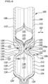
- the edge channel 136 comprises an edge channel section 137, which runs from a first end region 138, on which edge channel 136 is closed in a fluid-tight manner, along the web longitudinal direction 124 to a second end region 140.
- the edge channel 136 is closed in that the edge webs 134 and 134 'are lowered so far that they touch each other in order to form a medium passage 150 through which the first fluid reaction medium and/or the second fluid reaction medium passes transversely to the longitudinal direction 148 of the edge channel 136 can enter the respectively assigned first flow field 106 or second flow field 110.
- the edge webs 134 and 134' are also lowered, so that a narrowing 142 is formed in the flow-through cross section of the edge channel 136.
- the edge webs 134 and 134 ' can rest against each other in the area of the constriction 142, for example due to a thickening of the material, so that the flow-through cross section of the edge channel 136 in the area of the constriction 142 is reduced to zero.
- the constriction 142 forms an interruption 143 of the edge channel 136, and the edge channel 136 can only be flowed through by the further fluid medium, in particular the cooling medium, in the edge channel section 137, between the first end region 138 and the second end region 140.
- the bipolar plate 100 further comprises one or more fluid connections 144, for example a first fluid connection 144a and a second fluid connection 144b, through which the edge channel 136 is connected to the adjacent closed fluid channel 132, so that the further fluid medium, in particular the cooling medium, from the edge channel 136 can flow into the adjacent closed fluid channel 132 or from the adjacent closed fluid channel 132 into the edge channel 136.
- one or more fluid connections 144 for example a first fluid connection 144a and a second fluid connection 144b, through which the edge channel 136 is connected to the adjacent closed fluid channel 132, so that the further fluid medium, in particular the cooling medium, from the edge channel 136 can flow into the adjacent closed fluid channel 132 or from the adjacent closed fluid channel 132 into the edge channel 136.
- the fluid connections 144a, 144b are formed in that the channel base sections 114, 114 'of the first bipolar plate layer 104 or the second bipolar plate layer 108 in the area of the fluid connections 144a and 144b are raised in the stacking direction 102, so that in these areas the first Bipolar plate layer 104 and the second bipolar plate layer 108 are spaced apart from one another along the stacking direction 102 and form a connecting channel 146 between them, which is aligned transversely, preferably substantially perpendicularly, to the longitudinal direction 148 of the edge channel 136, which is aligned with the web longitudinal direction 124 of the edge webs 134 and 134 ' matches.
- the flow of this fluid medium can be divided in the desired manner between the fluid channel 132 and the edge channel 136, for example in order to transport the further fluid, in particular the cooling medium, in sections to areas of the first flow field 106 or the second flow field 110, which are connected to electrochemically active areas of adjacent electrochemically active units, and fed into an adjacent fluid channel at other points in a defined manner in order to achieve a higher cooling effect at the feed points.
- the ones in the Fig. 1 to 6 The first embodiment of a bipolar plate 100 shown makes it possible in particular to influence the flow of the further fluid medium, in particular the cooling medium, through the bipolar plate 100 in the desired manner.
- the second embodiment of the bipolar plate 100 shown differs from that in the Fig. 1 to 6 illustrated first embodiment in that the edge channel 136 is not in fluid communication with an adjacent closed fluid channel 132, but with the adjacent flow field channel 126, which is open to the electrochemically active unit.
- the edge channel 136 in this embodiment has one or more fluid connections 144, for example a first fluid connection 144a and a second fluid connection 144b, which are designed as passage openings 152, which are arranged, for example, on the edge web 134 of the first bipolar plate layer 104.
- such a passage opening 152 is arranged at least partially on the tip 116 and/or at least partially on one of the flanks 120 of the edge web 134 of the first bipolar plate layer 104.
- the first fluid reaction medium which flows through the first flow field 106, can flow at the fluid connections 144a and 144b from the flow field channel 126, which is adjacent to the edge channel 136, into the edge channel 136 and/or out of the edge channel 136 flow into the flow field channel 126, which is adjacent to the edge channel 136.
- the edge channel 136 can be used to influence the distribution of the first fluid reaction medium over the first flow field 106.
- the connecting channels 146 between the edge channel 136 and the adjacent closed fluid channel 132, through which the further fluid medium, in particular the cooling medium, flows, are omitted in this embodiment.
- the narrowing 142 or interruption 143 of the edge channel 136 described above in connection with the first embodiment can be omitted or can also be used in this second embodiment to influence the flow of the first fluid reaction medium through the edge channel 136.
- FIG. 7 to 10 Illustrated second embodiment of a bipolar plate 100 for an electrochemical device in terms of structure, function and method of manufacture with that in the Fig. 1 to 6 illustrated first embodiment, to the above description reference is made in this respect.
Landscapes
- Life Sciences & Earth Sciences (AREA)
- Engineering & Computer Science (AREA)
- Manufacturing & Machinery (AREA)
- Sustainable Development (AREA)
- Sustainable Energy (AREA)
- Chemical & Material Sciences (AREA)
- Chemical Kinetics & Catalysis (AREA)
- Electrochemistry (AREA)
- General Chemical & Material Sciences (AREA)
- Electrolytic Production Of Non-Metals, Compounds, Apparatuses Therefor (AREA)
- Fuel Cell (AREA)
Claims (10)
- Plaque bipolaire pour un dispositif électrochimique, comprenant au moins une première couche de plaque bipolaire (104) et une seconde couche de plaque bipolaire (108), entre lesquelles est formé un canal périphérique (136) s'étendant dans une direction longitudinale (148), et un canal de fluide (125) s'étendant sensiblement parallèlement au canal périphérique (136),
caractérisée en ce quela plaque bipolaire (100) comprend au moins une liaison fluidique (144) via laquelle un milieu fluide peut s'écouler du canal périphérique (136) dans le canal de fluide (125) adjacent et/ou du canal de fluide (125) adjacent dans le canal périphérique (136),le canal périphérique (136) présentant un rétrécissement (142) et/ou une interruption (143) qui a/ont pour effet d'augmenter la part du milieu fluide traversant le canal périphérique (136) qui sort du canal périphérique (136) dans le canal de fluide (125) via la liaison fluidique (144) pendant le fonctionnement du dispositif électrochimique. - Plaque bipolaire selon la revendication 1, caractérisée en ce que le canal de fluide (125) est réalisé fermé par rapport à une unité électrochimiquement active du dispositif électrochimique.
- Plaque bipolaire selon l'une des revendications 1 ou 2, caractérisée en ce que le canal périphérique (136) peut être traversé par un fluide de refroidissement pendant le fonctionnement du dispositif électrochimique.
- Plaque bipolaire selon l'une des revendications 1 à 3, caractérisée en ce que la liaison fluidique (144) comprend un canal de liaison (146) délimité par la première couche de plaque bipolaire (104) et la seconde couche de plaque bipolaire (108), la première couche de plaque bipolaire (104) et la seconde couche de plaque bipolaire (108) étant espacées l'une de l'autre au niveau du canal de liaison (146) dans une direction d'empilement (102) du dispositif électrochimique.
- Plaque bipolaire selon la revendication 4, caractérisée en ce que le canal de liaison (146) s'étend transversalement à la direction longitudinale (148) du canal périphérique (136).
- Plaque bipolaire selon la revendication 1, caractérisée en ce que le canal de fluide (125) est réalisé ouvert par rapport à une unité électrochimiquement active du dispositif électrochimique.
- Plaque bipolaire selon la revendication 6, caractérisée en ce que le canal périphérique (136) peut être traversé par un milieu réactionnel fluide pendant le fonctionnement du dispositif électrochimique.
- Plaque bipolaire selon l'une des revendications 1 à 7, caractérisée en ce que la liaison fluidique (144) comprend au moins un orifice de passage (152) disposé dans une paroi de délimitation du canal périphérique (136).
- Plaque bipolaire selon la revendication 8, caractérisée en ce que l'orifice de passage (152) est disposé au moins partiellement sur un sommet (116) et/ou au moins partiellement sur un flanc (120) d'une nervure de bord (134) de la première couche de plaque bipolaire (104) ou de la seconde couche de plaque bipolaire (108).
- Dispositif électrochimique comprenant au moins une plaque bipolaire (100) selon l'une des revendications 1 à 9 et au moins une unité électrochimiquement active qui est en contact avec la plaque bipolaire (100).
Applications Claiming Priority (2)
| Application Number | Priority Date | Filing Date | Title |
|---|---|---|---|
| DE102020108945.7A DE102020108945A1 (de) | 2020-03-31 | 2020-03-31 | Bipolarplatte für eine elektrochemische Vorrichtung |
| PCT/EP2021/058181 WO2021198192A1 (fr) | 2020-03-31 | 2021-03-29 | Plaque bipolaire pour un dispositif électrochimique |
Publications (2)
| Publication Number | Publication Date |
|---|---|
| EP4128401A1 EP4128401A1 (fr) | 2023-02-08 |
| EP4128401B1 true EP4128401B1 (fr) | 2024-02-14 |
Family
ID=75362621
Family Applications (1)
| Application Number | Title | Priority Date | Filing Date |
|---|---|---|---|
| EP21716148.8A Active EP4128401B1 (fr) | 2020-03-31 | 2021-03-29 | Plaque bipolaire pour un dispositif électrochimique |
Country Status (5)
| Country | Link |
|---|---|
| US (1) | US20230016017A1 (fr) |
| EP (1) | EP4128401B1 (fr) |
| CN (1) | CN117716545A (fr) |
| DE (1) | DE102020108945A1 (fr) |
| WO (1) | WO2021198192A1 (fr) |
Family Cites Families (4)
| Publication number | Priority date | Publication date | Assignee | Title |
|---|---|---|---|---|
| DE102006056468A1 (de) * | 2005-11-28 | 2007-07-05 | Behr Gmbh & Co. Kg | Bipolarplatte, insbesondere für einen Brennstoffzellenstapel eines Fahrzeugs |
| DK176814B1 (da) * | 2007-07-18 | 2009-10-19 | Serenergy As | Bipolar plade til brændselscelle omfattende en by-passed snoet flow kanal til oxiderende gas; köleplade til brændselscelle omfattende en by-passed snoet kanal til kölegas; brændselscelle omfattende nævnte plader og deres brug. |
| DE102014221351A1 (de) | 2014-10-21 | 2016-04-21 | Volkswagen Ag | Brennstoffzelle |
| US10211477B2 (en) | 2016-08-10 | 2019-02-19 | GM Global Technology Operations LLC | Fuel cell stack assembly |
-
2020
- 2020-03-31 DE DE102020108945.7A patent/DE102020108945A1/de active Pending
-
2021
- 2021-03-29 WO PCT/EP2021/058181 patent/WO2021198192A1/fr active Application Filing
- 2021-03-29 CN CN202180023684.5A patent/CN117716545A/zh active Pending
- 2021-03-29 EP EP21716148.8A patent/EP4128401B1/fr active Active
-
2022
- 2022-09-26 US US17/953,102 patent/US20230016017A1/en active Pending
Also Published As
| Publication number | Publication date |
|---|---|
| CN117716545A (zh) | 2024-03-15 |
| WO2021198192A1 (fr) | 2021-10-07 |
| DE102020108945A1 (de) | 2021-09-30 |
| EP4128401A1 (fr) | 2023-02-08 |
| US20230016017A1 (en) | 2023-01-19 |
Similar Documents
| Publication | Publication Date | Title |
|---|---|---|
| EP3631884B1 (fr) | Plaque de séparation pour un système électrochimique | |
| DE112005000945B4 (de) | Separator für eine Brennstoffzelle | |
| WO2018114819A1 (fr) | Plaque de séparation pour systeme électrochimique | |
| WO2017029158A1 (fr) | Plaque de séparation pour système électrochimique | |
| EP4128401B1 (fr) | Plaque bipolaire pour un dispositif électrochimique | |
| EP3123545B1 (fr) | Ensemble d'étanchéité pour dispositif électrochimique | |
| EP3652799B1 (fr) | Plaque bipolaire pour dispositif électrochimique | |
| EP3818197A1 (fr) | Dispositif électrochimique | |
| DE102022122717B3 (de) | Bipolarplatte und elektrochemische Zelle | |
| EP4082058B1 (fr) | Procédé de production d'une plaque de champ d'écoulement multicouche pour un dispositif électrochimique, et plaque de champ d'écoulement pour un dispositif électrochimique | |
| WO2021198184A1 (fr) | Plaque bipolaire pour dispositif électrochimique, et dispositif électrochimique | |
| DE102021134038A1 (de) | Verfahren zur Herstellung einer Bipolarplattenlage für eine Bipolarplatte einer elektrochemischen Einheit, Bipolarplattenlage für eine Bipolarplatte einer elektrochemischen Einheit und elektrochemische Einheit für eine elektrochemische Vorrichtung | |
| DE102022113249A1 (de) | Elektrochemische Vorrichtung | |
| WO2024028095A2 (fr) | Procédé d'assemblage par liaison de matière d'une première couche de plaque bipolaire et d'une seconde couche de plaque bipolaire, plaque bipolaire pour une unité électrochimique d'un dispositif électrochimique et dispositif électrochimique | |
| DE102022203540A1 (de) | Separatorplatte mit homogenisierter sickenkraft im portbereich | |
| DE102024100179A1 (de) | Modulare bipolarplatte für eine brennstoffzelle | |
| WO2024028094A2 (fr) | Plaque bipolaire destinée à une unité électrochimique d'un dispositif électrochimique et dispositif électrochimique | |
| DE102022119219A1 (de) | Bipolarplatte für eine elektrochemische Einheit einer elektrochemischen Vorrichtung und elektrochemische Vorrichtung | |
| WO2019162106A1 (fr) | Structure d'alimentation en milieu pour dispositif électrochimique | |
| DE102022119209A1 (de) | Bipolarplatte für eine elektrochemische Einheit einer elektrochemischen Vorrichtung und elektrochemische Vorrichtung | |
| DE202022104559U1 (de) | Separatorplatte für ein elektrochemisches System | |
| WO2019011869A1 (fr) | Système d'étanchéité conçu pour un dispositif électrochimique | |
| DE102023204882A1 (de) | Bipolarplatte für ein elektrochemisches System und Anordnung derartiger Bipolarplatten | |
| AT525448A4 (de) | Anschlusseinheit für Zellstapel |
Legal Events
| Date | Code | Title | Description |
|---|---|---|---|
| STAA | Information on the status of an ep patent application or granted ep patent |
Free format text: STATUS: UNKNOWN |
|
| STAA | Information on the status of an ep patent application or granted ep patent |
Free format text: STATUS: THE INTERNATIONAL PUBLICATION HAS BEEN MADE |
|
| PUAI | Public reference made under article 153(3) epc to a published international application that has entered the european phase |
Free format text: ORIGINAL CODE: 0009012 |
|
| STAA | Information on the status of an ep patent application or granted ep patent |
Free format text: STATUS: REQUEST FOR EXAMINATION WAS MADE |
|
| 17P | Request for examination filed |
Effective date: 20220927 |
|
| AK | Designated contracting states |
Kind code of ref document: A1 Designated state(s): AL AT BE BG CH CY CZ DE DK EE ES FI FR GB GR HR HU IE IS IT LI LT LU LV MC MK MT NL NO PL PT RO RS SE SI SK SM TR |
|
| P01 | Opt-out of the competence of the unified patent court (upc) registered |
Effective date: 20230519 |
|
| DAV | Request for validation of the european patent (deleted) | ||
| DAX | Request for extension of the european patent (deleted) | ||
| GRAP | Despatch of communication of intention to grant a patent |
Free format text: ORIGINAL CODE: EPIDOSNIGR1 |
|
| STAA | Information on the status of an ep patent application or granted ep patent |
Free format text: STATUS: GRANT OF PATENT IS INTENDED |
|
| RIC1 | Information provided on ipc code assigned before grant |
Ipc: H01M 8/10 20160101ALN20230825BHEP Ipc: H01M 8/1018 20160101ALI20230825BHEP Ipc: H01M 8/0267 20160101ALI20230825BHEP Ipc: H01M 8/0258 20160101AFI20230825BHEP |
|
| INTG | Intention to grant announced |
Effective date: 20230913 |
|
| GRAS | Grant fee paid |
Free format text: ORIGINAL CODE: EPIDOSNIGR3 |
|
| GRAA | (expected) grant |
Free format text: ORIGINAL CODE: 0009210 |
|
| STAA | Information on the status of an ep patent application or granted ep patent |
Free format text: STATUS: THE PATENT HAS BEEN GRANTED |
|
| AK | Designated contracting states |
Kind code of ref document: B1 Designated state(s): AL AT BE BG CH CY CZ DE DK EE ES FI FR GB GR HR HU IE IS IT LI LT LU LV MC MK MT NL NO PL PT RO RS SE SI SK SM TR |
|
| REG | Reference to a national code |
Ref country code: GB Ref legal event code: FG4D Free format text: NOT ENGLISH |
|
| REG | Reference to a national code |
Ref country code: CH Ref legal event code: EP |
|
| REG | Reference to a national code |
Ref country code: DE Ref legal event code: R096 Ref document number: 502021002692 Country of ref document: DE |
|
| REG | Reference to a national code |
Ref country code: IE Ref legal event code: FG4D Free format text: LANGUAGE OF EP DOCUMENT: GERMAN |