EP4128401B1 - Bipolar plate for an electrochemical device - Google Patents
Bipolar plate for an electrochemical device Download PDFInfo
- Publication number
- EP4128401B1 EP4128401B1 EP21716148.8A EP21716148A EP4128401B1 EP 4128401 B1 EP4128401 B1 EP 4128401B1 EP 21716148 A EP21716148 A EP 21716148A EP 4128401 B1 EP4128401 B1 EP 4128401B1
- Authority
- EP
- European Patent Office
- Prior art keywords
- bipolar plate
- channel
- fluid
- edge
- electrochemical device
- Prior art date
- Legal status (The legal status is an assumption and is not a legal conclusion. Google has not performed a legal analysis and makes no representation as to the accuracy of the status listed.)
- Active
Links
- 239000012530 fluid Substances 0.000 claims description 98
- 239000012429 reaction media Substances 0.000 claims description 21
- 239000002826 coolant Substances 0.000 claims description 11
- 238000005304 joining Methods 0.000 description 5
- 239000000446 fuel Substances 0.000 description 4
- 238000000034 method Methods 0.000 description 4
- 239000012528 membrane Substances 0.000 description 3
- 230000001154 acute effect Effects 0.000 description 2
- 238000001816 cooling Methods 0.000 description 2
- 238000009826 distribution Methods 0.000 description 2
- 238000003487 electrochemical reaction Methods 0.000 description 2
- 238000005868 electrolysis reaction Methods 0.000 description 2
- 239000005518 polymer electrolyte Substances 0.000 description 2
- 238000003466 welding Methods 0.000 description 2
- 239000000853 adhesive Substances 0.000 description 1
- 230000001070 adhesive effect Effects 0.000 description 1
- 239000011324 bead Substances 0.000 description 1
- 238000005520 cutting process Methods 0.000 description 1
- 230000007423 decrease Effects 0.000 description 1
- 238000009792 diffusion process Methods 0.000 description 1
- 230000000694 effects Effects 0.000 description 1
- 230000001771 impaired effect Effects 0.000 description 1
- 238000003698 laser cutting Methods 0.000 description 1
- 238000004519 manufacturing process Methods 0.000 description 1
- 239000000463 material Substances 0.000 description 1
- 239000007769 metal material Substances 0.000 description 1
- 239000003566 sealing material Substances 0.000 description 1
- 238000005476 soldering Methods 0.000 description 1
- 230000008719 thickening Effects 0.000 description 1
- 238000011144 upstream manufacturing Methods 0.000 description 1
Images


Classifications
-
- H—ELECTRICITY
- H01—ELECTRIC ELEMENTS
- H01M—PROCESSES OR MEANS, e.g. BATTERIES, FOR THE DIRECT CONVERSION OF CHEMICAL ENERGY INTO ELECTRICAL ENERGY
- H01M8/00—Fuel cells; Manufacture thereof
- H01M8/02—Details
- H01M8/0202—Collectors; Separators, e.g. bipolar separators; Interconnectors
- H01M8/0267—Collectors; Separators, e.g. bipolar separators; Interconnectors having heating or cooling means, e.g. heaters or coolant flow channels
-
- H—ELECTRICITY
- H01—ELECTRIC ELEMENTS
- H01M—PROCESSES OR MEANS, e.g. BATTERIES, FOR THE DIRECT CONVERSION OF CHEMICAL ENERGY INTO ELECTRICAL ENERGY
- H01M8/00—Fuel cells; Manufacture thereof
- H01M8/02—Details
- H01M8/0202—Collectors; Separators, e.g. bipolar separators; Interconnectors
- H01M8/0258—Collectors; Separators, e.g. bipolar separators; Interconnectors characterised by the configuration of channels, e.g. by the flow field of the reactant or coolant
-
- H—ELECTRICITY
- H01—ELECTRIC ELEMENTS
- H01M—PROCESSES OR MEANS, e.g. BATTERIES, FOR THE DIRECT CONVERSION OF CHEMICAL ENERGY INTO ELECTRICAL ENERGY
- H01M8/00—Fuel cells; Manufacture thereof
- H01M8/10—Fuel cells with solid electrolytes
- H01M2008/1095—Fuel cells with polymeric electrolytes
-
- Y—GENERAL TAGGING OF NEW TECHNOLOGICAL DEVELOPMENTS; GENERAL TAGGING OF CROSS-SECTIONAL TECHNOLOGIES SPANNING OVER SEVERAL SECTIONS OF THE IPC; TECHNICAL SUBJECTS COVERED BY FORMER USPC CROSS-REFERENCE ART COLLECTIONS [XRACs] AND DIGESTS
- Y02—TECHNOLOGIES OR APPLICATIONS FOR MITIGATION OR ADAPTATION AGAINST CLIMATE CHANGE
- Y02E—REDUCTION OF GREENHOUSE GAS [GHG] EMISSIONS, RELATED TO ENERGY GENERATION, TRANSMISSION OR DISTRIBUTION
- Y02E60/00—Enabling technologies; Technologies with a potential or indirect contribution to GHG emissions mitigation
- Y02E60/30—Hydrogen technology
- Y02E60/50—Fuel cells
Definitions
- the present invention relates to a bipolar plate for an electrochemical device, which comprises at least a first bipolar plate layer and a second bipolar plate layer, between which an edge channel extending along a longitudinal direction is formed, and a fluid channel running essentially parallel to the edge channel.
- the DE 10 2006 056468 A1 discloses a bipolar plate for an electrochemical device according to the preamble of claim 1.
- the US 2010/136452 A1 discloses a bipolar plate for an electrochemical device comprising fluid channels which run parallel to one another and are connected to one another by a fluid connection through which a fluid medium can flow from one fluid channel into an adjacent fluid channel.
- the present invention is based on the object of creating a bipolar plate of the type mentioned at the outset, in which at least one edge channel section of the edge channel can be flowed through with a fluid medium to be supplied to the electrochemical device, for example with a fluid reaction medium or with a cooling medium, although the edge channel is not a direct one Has fluid connection to a medium channel through which the fluid medium in question is supplied to the electrochemical device.
- the present invention is based on the concept of providing a fluid connection to an edge channel section separated from the media supply in order to specifically use the edge channel section to distribute a fluid medium in the interior of the bipolar plate and / or in the flow fields formed on the outside of the bipolar plate.
- the edge channel is provided with one or more constrictions and/or with one or more interruptions.
- the fluid channel is designed to be closed relative to an electrochemically active unit of the electrochemical device.
- a cooling medium can preferably flow through the edge channel during operation of the electrochemical device.
- the fluid connection preferably comprises a connecting channel which is delimited by the first bipolar plate layer and the second bipolar plate layer, the first bipolar plate layer and the second bipolar plate layer in the area of the connecting channel along a stacking direction of the electrochemical device, along which the bipolar plates and the electrochemically active units of the electrochemical device follow each other, are spaced apart from each other.
- Such a connecting channel preferably runs transversely, in particular essentially perpendicular, to the longitudinal direction of the edge channel.
- the edge channel has a narrowing and/or an interruption through which the portion of the fluid medium flowing through the edge channel exits from the edge channel into the fluid channel during operation of the electrochemical device through the fluid connection is enlarged.
- the extent of such a narrowing and/or interruption in the longitudinal direction of the edge channel is so short that the mechanical support of a gas diffusion layer of the electrochemically active unit of the electrochemical device on the bipolar plate is not impaired by the narrowing or interruption.
- the fluid channel is designed to be open to an electrochemically active unit of the electrochemical device.
- a fluid reaction medium can flow through the edge channel during operation of the electrochemical device.
- Such a fluid reaction medium contains at least one electrochemically active species which takes part in the electrochemical reactions which take place in the electrochemically active unit adjacent to the bipolar plate.
- the fluid reaction medium through which the edge channel can flow can in particular be an anode gas or a cathode gas of the electrochemical device.
- the fluid connection can, for example, comprise at least one passage opening which is arranged in a boundary wall of the edge channel.
- the passage opening is arranged at least partially on a crest and/or at least partially on a flank of an edge web of the first bipolar plate layer or the second bipolar plate layer.
- the edge channel is preferably delimited by an edge web of the first bipolar plate layer and by an edge web of the second bipolar plate layer.
- the bipolar plate according to the invention is particularly suitable for use in an electrochemical device which comprises at least one electrochemically active unit and at least one bipolar plate according to the invention.
- the electrochemically active unit is preferably arranged adjacent to the bipolar plate.
- the bipolar plate preferably has a flow field which includes flow field channels that are open to the electrochemically active unit. This makes it possible for a fluid reaction medium to reach the electrochemically active unit from the relevant flow field.
- a passage opening in an edge web, which delimits the edge channel of the bipolar plate is preferably created by a cutting process, in particular a laser cutting process, on the bipolar plate, in particular on the first bipolar plate layer or on the second bipolar plate layer.
- the electrochemical device can in particular be designed as a fuel cell device, preferably as a PEM (polymer electrolyte membrane) fuel cell device, as an electrolysis cell or as a redox flow battery.
- a fuel cell device preferably as a PEM (polymer electrolyte membrane) fuel cell device, as an electrolysis cell or as a redox flow battery.
- PEM polymer electrolyte membrane
- the electrochemically active unit of the electrochemical device preferably comprises a polymer electrolyte membrane (PEM).
- PEM polymer electrolyte membrane
- the first bipolar plate layer and/or the second bipolar plate layer of the bipolar plate are preferably formed from a metallic material.
- Bipolar plate shown in detail and designated as a whole by 100 serves as a component for an electrochemical unit of an electrochemical device (not shown as a whole), for example a fuel cell stack or an electrolyzer, the electrochemical device comprising a stack which has a plurality of electrochemical units following one another in a stacking direction 102 , for example fuel cell units or electrolysis units, and a clamping device (not shown) for applying a clamping force directed parallel to the stacking direction 102 to the electrochemical units.
- an electrochemical unit of an electrochemical device for example a fuel cell stack or an electrolyzer
- the electrochemical device comprising a stack which has a plurality of electrochemical units following one another in a stacking direction 102 , for example fuel cell units or electrolysis units
- a clamping device (not shown) for applying a clamping force directed parallel to the stacking direction 102 to the electrochemical units.
- the bipolar plate 100 comprises a first bipolar plate layer 104, on which a first flow field 106 for a first fluid reaction medium is formed, and a second bipolar plate layer 108, which is fixed in a fluid-tight manner, for example by a weld seam arrangement, to the first bipolar plate layer 104 and to which a second flow field 110 is designed for a second fluid reaction medium.
- the first bipolar plate layer 104 has webs 112 and channel base sections 114 lying between two webs 112.
- each of the webs 112 has a tip 116, with which the web 112 in question rests against an electrochemically active unit of the electrochemical device adjacent to the bipolar plate 100 in the assembled state of the electrochemical device.
- Such an electrochemically active unit can in particular be designed as a membrane electrode arrangement (MEA).
- MEA membrane electrode arrangement
- Each tip 116 with a contact surface 118 which is aligned essentially perpendicular to the stacking direction 102, lies essentially flat against a boundary surface of the electrochemically active unit facing the bipolar plate 100, which is also aligned essentially perpendicular to the stacking direction 102.
- each web 112 includes two flanks 120, which are inclined at an acute angle relative to the stacking direction 102.
- a channel base section 114 of the first bipolar plate layer 104 which connects the two adjacent webs 112 to one another, extends between the outer edges 122 of two adjacent webs 112 facing away from the respective tip 116.
- Each of the webs 112 extends along a web longitudinal direction 124, which is aligned essentially perpendicular to the stacking direction 102.
- two adjacent webs 112 and the channel base section 114 connecting the two webs 112 together with the (not shown) electrochemically active unit each delimit a fluid channel 125, which is a flow field channel 126 of the first flow field 106.
- Each flow field channel 126 of the flow field 106 can be flowed through by the first fluid reaction medium, to which the first flow field 106 is assigned, along a flow direction 128, which within a flow field channel 126 is essentially parallel to the web longitudinal directions 124 of the webs 112 of the webs 112 delimiting the relevant flow field channel 126 first flow field 106 is aligned.
- the flow field channels 126 of the first flow field 106 open at their upstream end (not shown) into a medium supply area of the first flow field 106 and at their downstream end into a medium discharge area of the first flow field 106.
- the first fluid reaction medium to which the first flow field 106 is assigned, enters the medium supply region of the first flow field 106 through a medium supply channel (preferably running essentially parallel to the stacking direction 102, not shown), from where it is distributed to the various flow field channels 126 of the first flow field 106 and flows through them along the flow direction 128.
- a medium supply channel preferably running essentially parallel to the stacking direction 102, not shown
- the first fluid reaction medium can in particular be an anode gas or a cathode gas for the electrochemical device.
- the first fluid reaction medium passes from the flow field channels 126 to the electrochemically active unit, where the respective electrochemically active species from the first fluid reaction medium is consumed in the course of the electrochemical reactions taking place in the electrochemically active unit, so that the concentration of the electrochemically active species in the The first fluid reaction medium flowing through the flow field channels 126 decreases along the flow direction 128.
- the first bipolar plate layer 104 and the second bipolar plate layer 108 are connected to one another in a fluid-tight manner along one or more joining lines 130.
- any cohesive joining process can be considered for producing the at least one joining line 130.
- the joining line 130 is a soldering line, a welding line or an adhesive line or is formed by a bead of a, preferably elastomeric, sealing material.
- a joining line 130 can be generated in particular by a laser welding process on the bipolar plate 100.
- Closed fluid channels 132 for a further fluid medium are formed between the first bipolar plate layer 104 and the second bipolar plate layer 108.
- This further fluid medium can be different from the first fluid reaction medium to which the first flow field 106 is assigned.
- the further fluid medium can in particular be a cooling medium for cooling the electrochemical device.
- the closed fluid channels 132 formed between the first bipolar plate layer 104 and the second bipolar plate layer 108 are cooling medium channels 133 in this case.
- the closed fluid channels 132 through which the further fluid medium can flow are designed to be closed relative to the electrochemically active unit, so that the further fluid medium, in particular the cooling medium, cannot pass from the closed fluid channels 132 into the electrochemically active unit.
- the second bipolar plate layer 108 also has webs 112' and channel base sections 114' located between two webs 112'.
- Each of the webs 112' has a tip 116', with which the web 112' rests on an electrochemically active unit (not shown) of a further electrochemical unit of the electrochemical device adjacent to the bipolar plate 100.
- Each tip 116 'with a contact surface 118' which is aligned essentially perpendicular to the stacking direction 102, lies essentially flat on a boundary surface of the electrochemically active unit of the adjacent electrochemical unit facing the bipolar plate 100, which is also aligned essentially perpendicular to the stacking direction 102 is on.
- each web 112 ' comprises two flanks 120', which are inclined at an acute angle relative to the stacking direction 102.
- a channel base section 114' of the second bipolar plate layer 108 extends between the outer edges 122' of two adjacent webs 112' facing away from the respective tip 116', which connects the two adjacent webs 112' to one another.
- the edge channel 136 comprises an edge channel section 137, which runs from a first end region 138, on which edge channel 136 is closed in a fluid-tight manner, along the web longitudinal direction 124 to a second end region 140.
- the edge channel 136 is closed in that the edge webs 134 and 134 'are lowered so far that they touch each other in order to form a medium passage 150 through which the first fluid reaction medium and/or the second fluid reaction medium passes transversely to the longitudinal direction 148 of the edge channel 136 can enter the respectively assigned first flow field 106 or second flow field 110.
- the edge webs 134 and 134' are also lowered, so that a narrowing 142 is formed in the flow-through cross section of the edge channel 136.
- the edge webs 134 and 134 ' can rest against each other in the area of the constriction 142, for example due to a thickening of the material, so that the flow-through cross section of the edge channel 136 in the area of the constriction 142 is reduced to zero.
- the constriction 142 forms an interruption 143 of the edge channel 136, and the edge channel 136 can only be flowed through by the further fluid medium, in particular the cooling medium, in the edge channel section 137, between the first end region 138 and the second end region 140.
- the bipolar plate 100 further comprises one or more fluid connections 144, for example a first fluid connection 144a and a second fluid connection 144b, through which the edge channel 136 is connected to the adjacent closed fluid channel 132, so that the further fluid medium, in particular the cooling medium, from the edge channel 136 can flow into the adjacent closed fluid channel 132 or from the adjacent closed fluid channel 132 into the edge channel 136.
- one or more fluid connections 144 for example a first fluid connection 144a and a second fluid connection 144b, through which the edge channel 136 is connected to the adjacent closed fluid channel 132, so that the further fluid medium, in particular the cooling medium, from the edge channel 136 can flow into the adjacent closed fluid channel 132 or from the adjacent closed fluid channel 132 into the edge channel 136.
- the fluid connections 144a, 144b are formed in that the channel base sections 114, 114 'of the first bipolar plate layer 104 or the second bipolar plate layer 108 in the area of the fluid connections 144a and 144b are raised in the stacking direction 102, so that in these areas the first Bipolar plate layer 104 and the second bipolar plate layer 108 are spaced apart from one another along the stacking direction 102 and form a connecting channel 146 between them, which is aligned transversely, preferably substantially perpendicularly, to the longitudinal direction 148 of the edge channel 136, which is aligned with the web longitudinal direction 124 of the edge webs 134 and 134 ' matches.
- the flow of this fluid medium can be divided in the desired manner between the fluid channel 132 and the edge channel 136, for example in order to transport the further fluid, in particular the cooling medium, in sections to areas of the first flow field 106 or the second flow field 110, which are connected to electrochemically active areas of adjacent electrochemically active units, and fed into an adjacent fluid channel at other points in a defined manner in order to achieve a higher cooling effect at the feed points.
- the ones in the Fig. 1 to 6 The first embodiment of a bipolar plate 100 shown makes it possible in particular to influence the flow of the further fluid medium, in particular the cooling medium, through the bipolar plate 100 in the desired manner.
- the second embodiment of the bipolar plate 100 shown differs from that in the Fig. 1 to 6 illustrated first embodiment in that the edge channel 136 is not in fluid communication with an adjacent closed fluid channel 132, but with the adjacent flow field channel 126, which is open to the electrochemically active unit.
- the edge channel 136 in this embodiment has one or more fluid connections 144, for example a first fluid connection 144a and a second fluid connection 144b, which are designed as passage openings 152, which are arranged, for example, on the edge web 134 of the first bipolar plate layer 104.
- such a passage opening 152 is arranged at least partially on the tip 116 and/or at least partially on one of the flanks 120 of the edge web 134 of the first bipolar plate layer 104.
- the first fluid reaction medium which flows through the first flow field 106, can flow at the fluid connections 144a and 144b from the flow field channel 126, which is adjacent to the edge channel 136, into the edge channel 136 and/or out of the edge channel 136 flow into the flow field channel 126, which is adjacent to the edge channel 136.
- the edge channel 136 can be used to influence the distribution of the first fluid reaction medium over the first flow field 106.
- the connecting channels 146 between the edge channel 136 and the adjacent closed fluid channel 132, through which the further fluid medium, in particular the cooling medium, flows, are omitted in this embodiment.
- the narrowing 142 or interruption 143 of the edge channel 136 described above in connection with the first embodiment can be omitted or can also be used in this second embodiment to influence the flow of the first fluid reaction medium through the edge channel 136.
- FIG. 7 to 10 Illustrated second embodiment of a bipolar plate 100 for an electrochemical device in terms of structure, function and method of manufacture with that in the Fig. 1 to 6 illustrated first embodiment, to the above description reference is made in this respect.
Description
Die vorliegende Erfindung betrifft eine Bipolarplatte für eine elektrochemische Vorrichtung, die mindestens eine erste Bipolarplattenlage und eine zweite Bipolarplattenlage, zwischen denen ein sich längs einer Längsrichtung erstreckender Randkanal ausgebildet ist, und einen im Wesentlichen parallel zu dem Randkanal verlaufenden Fluidkanal umfasst.The present invention relates to a bipolar plate for an electrochemical device, which comprises at least a first bipolar plate layer and a second bipolar plate layer, between which an edge channel extending along a longitudinal direction is formed, and a fluid channel running essentially parallel to the edge channel.
Wenn eine solche Bipolarplatte mit einer Strömungspforte versehen ist, durch welche ein fluides Reaktionsmedium in ein an der Bipolarplatte ausgebildetes Strömungsfeld einströmt, so wird der Randkanal nicht von einem fluiden Medium durchströmt, da eine Schweißnaht um den Bereich der Strömungspforte den Randkanal von der Medienzuströmung abtrennt.If such a bipolar plate is provided with a flow port through which a fluid reaction medium flows into a flow field formed on the bipolar plate, the edge channel is not flowed through by a fluid medium, since a weld seam around the area of the flow port separates the edge channel from the media inflow.
Die
Die
Der vorliegenden Erfindung liegt die Aufgabe zugrunde, eine Bipolarplatte der eingangs genannten Art zu schaffen, bei welcher zumindest ein Randkanalabschnitt des Randkanals mit einem der elektrochemischen Vorrichtung zuzuführenden fluiden Medium durchströmbar ist, beispielsweise mit einem fluiden Reaktionsmedium oder mit einem Kühlmedium, obwohl der Randkanal keine direkte Fluidverbindung zu einem Mediumkanal aufweist, durch welchen das betreffende fluide Medium der elektrochemischen Vorrichtung zugeführt wird.The present invention is based on the object of creating a bipolar plate of the type mentioned at the outset, in which at least one edge channel section of the edge channel can be flowed through with a fluid medium to be supplied to the electrochemical device, for example with a fluid reaction medium or with a cooling medium, although the edge channel is not a direct one Has fluid connection to a medium channel through which the fluid medium in question is supplied to the electrochemical device.
Diese Aufgabe wird durch eine Bipolarplatte nach Anspruch 1 gelöst.This task is achieved by a bipolar plate according to
Der vorliegenden Erfindung liegt das Konzept zugrunde, eine Fluidverbindung zu einem von der Medienzufuhr abgetrennten Randkanalabschnitt zur Verfügung zu stellen, um den Randkanalabschnitt gezielt zur Verteilung eines fluiden Mediums im Innenraum der Bipolarplatte und/oder in den an der Außenseite der Bipolarplatte ausgebildeten Strömungsfeldern nutzen zu können.The present invention is based on the concept of providing a fluid connection to an edge channel section separated from the media supply in order to specifically use the edge channel section to distribute a fluid medium in the interior of the bipolar plate and / or in the flow fields formed on the outside of the bipolar plate.
Um die Strömung des den Randkanal durchströmenden fluiden Mediums zu den elektrochemisch aktiven Bereichen einer der Bipolarplatte benachbarten elektrochemisch aktiven Einheit gezielt einstellen zu können, ist vorgesehen, dass der Randkanal mit einer oder mehreren Verengungen und/oder mit einer oder mit mehreren Unterbrechungen versehen ist.In order to be able to specifically adjust the flow of the fluid medium flowing through the edge channel to the electrochemically active areas of an electrochemically active unit adjacent to the bipolar plate, it is provided that the edge channel is provided with one or more constrictions and/or with one or more interruptions.
Bei einer besonderen Ausgestaltung der Erfindung ist vorgesehen, dass der Fluidkanal gegenüber einer elektrochemisch aktiven Einheit der elektrochemischen Vorrichtung geschlossen ausgebildet ist.In a particular embodiment of the invention it is provided that the fluid channel is designed to be closed relative to an electrochemically active unit of the electrochemical device.
In diesem Fall ist der Randkanal vorzugsweise im Betrieb der elektrochemischen Vorrichtung von einem Kühlmedium durchströmbar.In this case, a cooling medium can preferably flow through the edge channel during operation of the electrochemical device.
Die Fluidverbindung umfasst vorzugsweise einen Verbindungskanal, der durch die erste Bipolarplattenlage und die zweite Bipolarplattenlage begrenzt ist, wobei die erste Bipolarplattenlage und die zweite Bipolarplattenlage im Bereich des Verbindungskanals längs einer Stapelrichtung der elektrochemischen Vorrichtung, längs welcher die Bipolarplatten und die elektrochemisch aktiven Einheiten der elektrochemischen Vorrichtung aufeinander folgen, voneinander beabstandet sind.The fluid connection preferably comprises a connecting channel which is delimited by the first bipolar plate layer and the second bipolar plate layer, the first bipolar plate layer and the second bipolar plate layer in the area of the connecting channel along a stacking direction of the electrochemical device, along which the bipolar plates and the electrochemically active units of the electrochemical device follow each other, are spaced apart from each other.
Ein solcher Verbindungskanal verläuft vorzugsweise quer, insbesondere im Wesentlichen senkrecht, zu der Längsrichtung des Randkanals.Such a connecting channel preferably runs transversely, in particular essentially perpendicular, to the longitudinal direction of the edge channel.
Der Randkanal weist eine Verengung und/oder eine Unterbrechung auf, durch welche der im Betrieb der elektrochemischen Vorrichtung durch die Fluidverbindung aus dem Randkanal in den Fluidkanal austretende Anteil des den Randkanal durchströmenden fluiden Mediums vergrößert wird. Durch eine solche Verengung und/oder Unterbrechung des Randkanals kann die Verteilung der Strömung des fluiden Mediums auf den Randkanal einerseits und auf den benachbarten Fluidkanal andererseits in gewünschter Weise eingestellt werden.The edge channel has a narrowing and/or an interruption through which the portion of the fluid medium flowing through the edge channel exits from the edge channel into the fluid channel during operation of the electrochemical device through the fluid connection is enlarged. By narrowing and/or interrupting the edge channel in this way, the distribution of the flow of the fluid medium to the edge channel on the one hand and to the adjacent fluid channel on the other hand can be adjusted in the desired manner.
Vorzugsweise ist die Ausdehnung einer solchen Verengung und/oder Unterbrechung in der Längsrichtung des Randkanals so kurz, dass die mechanische Abstützung einer Gasdiffusionslage der elektrochemisch aktiven Einheit der elektrochemischen Vorrichtung an der Bipolarplatte durch die Verengung beziehungsweise Unterbrechung nicht beeinträchtigt wird.Preferably, the extent of such a narrowing and/or interruption in the longitudinal direction of the edge channel is so short that the mechanical support of a gas diffusion layer of the electrochemically active unit of the electrochemical device on the bipolar plate is not impaired by the narrowing or interruption.
Bei einer anderen besonderen Ausgestaltung der Erfindung ist vorgesehen, dass der Fluidkanal gegenüber einer elektrochemisch aktiven Einheit der elektrochemischen Vorrichtung offen ausgebildet ist.In another special embodiment of the invention it is provided that the fluid channel is designed to be open to an electrochemically active unit of the electrochemical device.
In diesem Fall ist vorzugsweise vorgesehen, dass der Randkanal im Betrieb der elektrochemischen Vorrichtung von einem fluiden Reaktionsmedium durchströmbar ist.In this case, it is preferably provided that a fluid reaction medium can flow through the edge channel during operation of the electrochemical device.
Ein solches fluides Reaktionsmedium enthält mindestens eine elektrochemisch aktive Spezies, die an den elektrochemischen Reaktionen teilnimmt, welche in der der Bipolarplatte benachbarten elektrochemisch aktiven Einheit stattfinden.Such a fluid reaction medium contains at least one electrochemically active species which takes part in the electrochemical reactions which take place in the electrochemically active unit adjacent to the bipolar plate.
Das fluide Reaktionsmedium, von welchem der Randkanal durchströmbar ist, kann insbesondere ein Anodengas oder ein Kathodengas der elektrochemischen Vorrichtung sein.The fluid reaction medium through which the edge channel can flow can in particular be an anode gas or a cathode gas of the electrochemical device.
Die Fluidverbindung kann beispielsweise mindestens eine Durchtrittsöffnung umfassen, die in einer Begrenzungswand des Randkanals angeordnet ist.The fluid connection can, for example, comprise at least one passage opening which is arranged in a boundary wall of the edge channel.
Dabei kann insbesondere vorgesehen sein, dass die Durchtrittsöffnung zumindest teilweise an einer Kuppe und/oder zumindest teilweise an einer Flanke eines Randsteges der ersten Bipolarplattenlage oder der zweiten Bipolarplattenlage angeordnet ist.In particular, it can be provided that the passage opening is arranged at least partially on a crest and/or at least partially on a flank of an edge web of the first bipolar plate layer or the second bipolar plate layer.
Der Randkanal wird vorzugsweise von einem Randsteg der ersten Bipolarplattenlage und von einem Randsteg der zweiten Bipolarplattenlage begrenzt.The edge channel is preferably delimited by an edge web of the first bipolar plate layer and by an edge web of the second bipolar plate layer.
Die erfindungsgemäße Bipolarplatte eignet sich insbesondere zur Verwendung in einer elektrochemischen Vorrichtung, welche mindestens eine elektrochemisch aktive Einheit und mindestens eine erfindungsgemäße Bipolarplatte umfasst. Dabei ist die elektrochemisch aktive Einheit vorzugsweise benachbart zu der Bipolarplatte angeordnet.The bipolar plate according to the invention is particularly suitable for use in an electrochemical device which comprises at least one electrochemically active unit and at least one bipolar plate according to the invention. The electrochemically active unit is preferably arranged adjacent to the bipolar plate.
Insbesondere weist die Bipolarplatte vorzugsweise ein Strömungsfeld auf, welches Strömungsfeldkanäle umfasst, die zu der elektrochemisch aktiven Einheit hin offen sind. Hierdurch ist es möglich, dass ein fluides Reaktionsmedium aus dem betreffenden Strömungsfeld zu der elektrochemisch aktiven Einheit gelangt.In particular, the bipolar plate preferably has a flow field which includes flow field channels that are open to the electrochemically active unit. This makes it possible for a fluid reaction medium to reach the electrochemically active unit from the relevant flow field.
Eine Durchtrittsöffnung in einem Randsteg, welcher den Randkanal der Bipolarplatte begrenzt, wird vorzugsweise durch einen Schneidvorgang, insbesondere einen Laser-Schneidvorgang, an der Bipolarplatte, insbesondere an der ersten Bipolarplattenlage oder an der zweiten Bipolarplattenlage, erzeugt.A passage opening in an edge web, which delimits the edge channel of the bipolar plate, is preferably created by a cutting process, in particular a laser cutting process, on the bipolar plate, in particular on the first bipolar plate layer or on the second bipolar plate layer.
Die elektrochemische Vorrichtung kann insbesondere als eine Brennstoffzellenvorrichtung, vorzugsweise als eine PEM(Polymer-Elektrolyt-Membran)-Brennstoffzellenvorrichtung, als eine Elektrolysezelle oder als eine Redox-Flow-Batterie ausgebildet sein.The electrochemical device can in particular be designed as a fuel cell device, preferably as a PEM (polymer electrolyte membrane) fuel cell device, as an electrolysis cell or as a redox flow battery.
Die elektrochemisch aktive Einheit der elektrochemischen Vorrichtung umfasst vorzugsweise eine Polymer-Elektrolyt-Membran (PEM).The electrochemically active unit of the electrochemical device preferably comprises a polymer electrolyte membrane (PEM).
Die erste Bipolarplattenlage und/oder die zweite Bipolarplattenlage der Bipolarplatte sind vorzugsweise aus einem metallischen Material gebildet.The first bipolar plate layer and/or the second bipolar plate layer of the bipolar plate are preferably formed from a metallic material.
Weitere Merkmale und Vorteile der Erfindung sind Gegenstand der nachfolgenden Beschreibung und der zeichnerischen Darstellung von Ausführungsbeispielen.Further features and advantages of the invention are the subject of the following description and the graphic representation of exemplary embodiments.
In den Zeichnungen zeigen:
- Fig. 1
- eine ausschnittsweise perspektivische Darstellung einer erfindungsgemäßen Bipolarplatte für eine elektrochemische Vorrichtung, welche eine erste Bipolarplattenlage und eine zweite Bipolarplattenlage umfasst, zwischen denen ein sich längs einer Längsrichtung erstreckender Randkanal ausgebildet ist, und einen im Wesentlichen parallel zu dem Randkanal verlaufenden Fluidkanal umfasst, wobei die Bipolarplatte eine Fluidverbindung umfasst, durch welche ein fluides Medium aus dem Randkanal in den benachbarten Fluidkanal und/oder aus dem benachbarten Fluidkanal in den Randkanal ausströmen kann, und wobei der Fluidkanal gegenüber einer elektrochemisch aktiven Einheit der elektrochemischen Vorrichtung geschlossen ausgebildet ist;
- Fig. 2
- eine ausschnittsweise Draufsicht auf die Bipolarplatte aus
Fig. 1 ; - Fig. 3
- einen Längsschnitt durch die Bipolarplatte aus den
Fig. 1 und2 , längs der Linie 3 - 3 inFig. 2 ; - Fig. 4
- einen Querschnitt durch die Bipolarplatte aus den
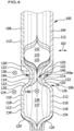
Fig. 1 bis 3 , längs der Linie 4 - 4 inFig. 2 ; - Fig. 5
- einen Längsschnitt durch die Bipolarplatte aus den
Fig. 1 bis 4 , längs der Linie 5 - 5 inFig. 2 ; - Fig. 6
- einen Querschnitt durch die Bipolarplatte aus den
Fig. 1 bis 5 , längs der Linie 6 - 6 inFig. 2 , - Fig. 7
- eine ausschnittsweise perspektivische Darstellung einer nicht erfindungsgemäßen zweiten Ausführungsform einer Bipolarplatte für eine elektrochemische Vorrichtung, welche eine erste Bipolarplattenlage und eine zweite Bipolarplattenlage umfasst, zwischen denen ein sich längs einer Längsrichtung erstreckender Randkanal ausgebildet ist, und einen im Wesentlichen parallel zu dem Randkanal verlaufenden Fluidkanal umfasst, wobei die Bipolarplatte eine Fluidverbindung umfasst, durch welche ein fluides Medium aus dem Randkanal in den benachbarten Fluidkanal und/oder aus dem benachbarten Fluidkanal in den Randkanal ausströmen kann, und wobei der Fluidkanal gegenüber einer elektrochemisch aktiven Einheit der elektrochemischen Vorrichtung offen ausgebildet ist und Durchtrittsöffnungen an einer Kuppe und/oder an einer Flanke eines Randsteges einer der Bipolarplattenlagen angeordnet sind;
- Fig. 8
- eine ausschnittsweise Draufsicht auf die Bipolarplatte aus
Fig. 7 ; - Fig. 9
- einen Querschnitt durch die Bipolarplatte aus den
Fig. 7 und8 , längs der Linie 9 - 9 inFig. 8 ; und - Fig. 10
- einen Querschnitt durch die Bipolarplatte aus den
Fig. 7 bis 9 , längs der Linie 10 - 10 inFig. 8 .
- Fig. 1
- a partial perspective view of a bipolar plate according to the invention for an electrochemical device, which comprises a first bipolar plate layer and a second bipolar plate layer, between which an edge channel extending along a longitudinal direction is formed, and comprises a fluid channel running essentially parallel to the edge channel, wherein the bipolar plate has a Fluid connection comprises, through which a fluid medium can flow out of the edge channel into the adjacent fluid channel and/or from the adjacent fluid channel into the edge channel, and wherein the fluid channel is designed to be closed relative to an electrochemically active unit of the electrochemical device;
- Fig. 2
- a partial top view of the bipolar plate
Fig. 1 ; - Fig. 3
- a longitudinal section through the bipolar plate
Fig. 1 and2 , along the line 3 - 3 inFig. 2 ; - Fig. 4
- a cross section through the bipolar plate
Fig. 1 to 3 , along the line 4 - 4 inFig. 2 ; - Fig. 5
- a longitudinal section through the bipolar plate
Fig. 1 to 4 , along the line 5 - 5 inFig. 2 ; - Fig. 6
- a cross section through the bipolar plate
Fig. 1 to 5 , along the line 6 - 6 inFig. 2 , - Fig. 7
- a partial perspective view of a second embodiment of a bipolar plate for an electrochemical device, which is not according to the invention, which comprises a first bipolar plate layer and a second bipolar plate layer, between which an edge channel extending along a longitudinal direction is formed, and comprises a fluid channel running essentially parallel to the edge channel, wherein the bipolar plate comprises a fluid connection through which a fluid medium can flow from the edge channel into the adjacent fluid channel and/or from the adjacent fluid channel into the edge channel, and wherein the fluid channel is designed to be open to an electrochemically active unit of the electrochemical device and has passage openings are arranged on a crest and/or on a flank of an edge web of one of the bipolar plate layers;
- Fig. 8
- a partial top view of the bipolar plate
Fig. 7 ; - Fig. 9
- a cross section through the bipolar plate
Fig. 7 and8th , along the line 9 - 9 inFig. 8 ; and - Fig. 10
- a cross section through the bipolar plate
Fig. 7 to 9 , along the line 10 - 10 inFig. 8 .
Gleiche oder funktional äquivalente Elemente sind in allen Figuren mit denselben Bezugszeichen bezeichnet.Identical or functionally equivalent elements are designated with the same reference numerals in all figures.
Eine in den
Die Bipolarplatte 100 umfasst bei dieser Ausführungsform eine erste Bipolarplattenlage 104, an welcher ein erstes Strömungsfeld 106 für ein erstes fluides Reaktionsmedium ausgebildet ist, und eine zweite Bipolarplattenlage 108, die fluiddicht, beispielsweise durch eine Schweißnahtanordnung, an der ersten Bipolarplattenlage 104 festgelegt ist und an welcher ein zweites Strömungsfeld 110 für ein zweites fluides Reaktionsmedium ausgebildet ist.In this embodiment, the
Die erste Bipolarplattenlage 104 weist Stege 112 und zwischen jeweils zwei Stegen 112 liegende Kanalgrundabschnitte 114 auf.The first
Wie am besten aus den Querschnitten der
Eine solche elektrochemisch aktive Einheit kann insbesondere als eine Membran-Elektroden-Anordnung (MEA) ausgebildet sein.Such an electrochemically active unit can in particular be designed as a membrane electrode arrangement (MEA).
Dabei liegt jede Kuppe 116 mit einer Anlagefläche 118, welche im Wesentlichen senkrecht zur Stapelrichtung 102 ausgerichtet ist, im Wesentlichen flächig an einer der Bipolarplatte 100 zugewandten Begrenzungsfläche der elektrochemisch aktiven Einheit, welche ebenfalls im Wesentlichen senkrecht zur Stapelrichtung 102 ausgerichtet ist, an.Each
Ferner umfasst jeder Steg 112 zwei Flanken 120, welche gegenüber der Stapelrichtung 102 um einen spitzen Winkel geneigt sind.Furthermore, each
Zwischen den der jeweiligen Kuppe 116 abgewandten äußeren Rändern 122 von zwei einander benachbarten Stegen 112 erstreckt sich jeweils ein Kanalgrundabschnitt 114 der ersten Bipolarplattenlage 104, welcher die beiden einander benachbarten Stege 112 miteinander verbindet.A
Jeder der Stege 112 erstreckt sich längs einer Steglängsrichtung 124, welche im Wesentlichen senkrecht zu der Stapelrichtung 102 ausgerichtet ist.Each of the
Wie am besten aus den
Jeder Strömungsfeldkanal 126 des Strömungsfeldes 106 ist von dem ersten fluiden Reaktionsmedium, welchem das erste Strömungsfeld 106 zugeordnet ist, längs einer Strömungsrichtung 128 durchströmbar, welche innerhalb eines Strömungsfeldkanals 126 im Wesentlichen parallel zu den Steg-Längsrichtungen 124 der den betreffenden Strömungsfeldkanal 126 begrenzenden Stege 112 des ersten Strömungsfelds 106 ausgerichtet ist.Each
Die Strömungsfeldkanäle 126 des ersten Strömungsfelds 106 münden an ihrem (nicht dargestellten) stromaufwärts liegenden Ende in einem Medium-Zuführbereich des ersten Strömungsfeldes 106 und an ihrem stromabwärts liegenden Ende in einem Medium-Abführbereich des ersten Strömungsfeldes 106.The
Im Betrieb der elektrochemischen Vorrichtung tritt das erste fluide Reaktionsmedium, welchem das erste Strömungsfeld 106 zugeordnet ist, durch einen (vorzugsweise im Wesentlichen parallel zur Stapelrichtung 102 verlaufenden, nicht dargestellten) Medium-Zuführkanal in den Medium-Zuführbereich des ersten Strömungsfeldes 106 ein, von wo es auf die verschiedenen Strömungsfeldkanäle 126 des ersten Strömungsfeldes 106 verteilt wird und dieselben längs der Strömungsrichtung 128 durchströmt.During operation of the electrochemical device, the first fluid reaction medium, to which the
Das erste fluide Reaktionsmedium kann insbesondere ein Anodengas oder ein Kathodengas für die elektrochemische Vorrichtung sein.The first fluid reaction medium can in particular be an anode gas or a cathode gas for the electrochemical device.
Das erste fluide Reaktionsmedium gelangt aus den Strömungsfeldkanälen 126 zu der elektrochemisch aktiven Einheit, wo die jeweils elektrochemisch aktive Spezies aus dem ersten fluiden Reaktionsmedium im Zuge der in der elektrochemisch aktiven Einheit ablaufenden elektrochemischen Reaktionen verbraucht wird, so dass die Konzentration der elektrochemisch aktiven Spezies in dem die Strömungsfeldkanäle 126 durchströmenden ersten fluiden Reaktionsmedium längs der Strömungsrichtung 128 abnimmt.The first fluid reaction medium passes from the
Die erste Bipolarplattenlage 104 und die zweite Bipolarplattenlage 108 sind längs einer oder mehrerer Fügelinien 130 fluiddicht miteinander verbunden.The first
Grundsätzlich kommt jedes stoffschlüssige Fügeverfahren für die Herstellung der mindestens einen Fügelinie 130 in Betracht.In principle, any cohesive joining process can be considered for producing the at least one joining
Insbesondere kann vorgesehen sein, dass die Fügelinie 130 eine Lötlinie, eine Schweißlinie oder eine Klebelinie ist oder durch einen Wulst eines, vorzugsweise elastomeren, Dichtungsmaterials gebildet ist.In particular, it can be provided that the joining
Eine Fügelinie 130 kann insbesondere durch einen Laserschweißvorgang an der Bipolarplatte 100 erzeugt sein.A joining
Zwischen der ersten Bipolarplattenlage 104 und der zweiten Bipolarplattenlage 108 sind geschlossene Fluidkanäle 132 für ein weiteres fluides Medium ausgebildet.Closed
Dieses weitere fluide Medium kann von dem ersten fluiden Reaktionsmedium, welchem das erste Strömungsfeld 106 zugeordnet ist, verschieden sein.This further fluid medium can be different from the first fluid reaction medium to which the
Das weitere fluide Medium kann insbesondere ein Kühlmedium zum Kühlen der elektrochemischen Vorrichtung sein. Die zwischen der ersten Bipolarplattenlage 104 und der zweiten Bipolarplattenlage 108 ausgebildeten geschlossenen Fluidkanäle 132 sind in diesem Fall Kühlmediumkanäle 133.The further fluid medium can in particular be a cooling medium for cooling the electrochemical device. The closed
Die von dem weiteren fluiden Medium durchströmbaren geschlossenen Fluidkanäle 132 sind gegenüber der elektrochemisch aktiven Einheit geschlossen ausgebildet, so dass das weitere fluide Medium, insbesondere das Kühlmedium, nicht aus den geschlossenen Fluidkanälen 132 in die elektrochemisch aktive Einheit gelangen kann.The closed
Auch die zweite Bipolarplattenlage 108 weist Stege 112' und zwischen jeweils zwei Stegen 112' liegende Kanalgrundabschnitte 114' auf.The second
Jeder der Stege 112' weist jeweils eine Kuppe 116' auf, mit welcher der Steg 112' an einer (nicht dargestellten) elektrochemisch aktiven Einheit einer der Bipolarplatte 100 benachbarten weiteren elektrochemischen Einheit der elektrochemischen Vorrichtung anliegt.Each of the webs 112' has a tip 116', with which the web 112' rests on an electrochemically active unit (not shown) of a further electrochemical unit of the electrochemical device adjacent to the
Dabei liegt jede Kuppe 116' mit einer Anlagefläche 118', welche im Wesentlichen senkrecht zur Stapelrichtung 102 ausgerichtet ist, im Wesentlichen flächig an einer der Bipolarplatte 100 zugewandten Begrenzungsfläche der elektrochemisch aktiven Einheit der benachbarten elektrochemischen Einheit, welche ebenfalls im Wesentlichen senkrecht zur Stapelrichtung 102 ausgerichtet ist, an.Each tip 116 'with a
Ferner umfasst jeder Steg 112' zwei Flanken 120', welche gegenüber der Stapelrichtung 102 um einen spitzen Winkel geneigt sind.Furthermore, each web 112 'comprises two
Zwischen den der jeweiligen Kuppe 116' abgewandten äußeren Rändern 122' von zwei einander benachbarten Stegen 112' erstreckt sich jeweils ein Kanalgrundabschnitt 114' der zweiten Bipolarplattenlage 108, welcher die beiden einander benachbarten Stege 112' miteinander verbindet.A channel base section 114' of the second
Jeder der Stege 112' erstreckt sich längs der Steglängsrichtung 124, welche im Wesentlichen senkrecht zu der Stapelrichtung 102 ausgerichtet ist.Each of the webs 112 'extends along the web
Ein am äußeren Rand der ersten Bipolarplattenlage 104 verlaufender Randsteg 134 und ein demselben gegenüberliegender, längs des Randes der zweiten Bipolarplattenlage 108 verlaufender Randsteg 134' begrenzen gemeinsam einen zwischen den Randstegen 134 und 134' ausgebildeten Randkanal 136 der Bipolarplatte 100.An
Wie am besten aus den
An dem ersten Endbereich 138 ist der Randkanal 136 dadurch verschlossen, dass die Randstege 134 und 134' so weit abgesenkt werden, dass sie einander berühren, um einen Mediumdurchtritt 150 zu bilden, durch welchen das erste fluide Reaktionsmedium und/oder das zweite fluide Reaktionsmedium quer zur Längsrichtung 148 des Randkanals 136 in das jeweils zugeordnete erste Strömungsfeld 106 beziehungsweise zweite Strömungsfeld 110 eintreten kann.At the
In dem zweiten Endbereich 140 sind im dargestellten Ausführungsbeispiel die Randstege 134 und 134' ebenfalls abgesenkt, so dass eine Verengung 142 im durchströmbaren Querschnitt des Randkanals 136 ausgebildet ist.In the
Wie aus dem Längsschnitt von
Die Bipolarplatte 100 umfasst ferner eine oder mehrere Fluidverbindungen 144, beispielsweise eine erste Fluidverbindung 144a und eine zweite Fluidverbindung 144b, durch welche der Randkanal 136 an den benachbarten geschlossenen Fluidkanal 132 angeschlossen ist, so dass das weitere fluide Medium, insbesondere das Kühlmedium, aus dem Randkanal 136 in den benachbarten geschlossenen Fluidkanal 132 oder aus dem benachbarten geschlossenen Fluidkanal 132 in den Randkanal 136 strömen kann.The
Wie am besten aus dem Längsschnitt von
Durch die Fluidverbindungen 144a und 144b zwischen dem Randkanal 136 und dem benachbarten geschlossenen Fluidkanal 132 kann die Strömung dieses fluiden Mediums in gewünschter Weise zwischen dem Fluidkanal 132 und dem Randkanal 136 aufgeteilt werden, um beispielsweise das weitere Fluid, insbesondere das Kühlmedium, abschnittsweise an Bereichen des ersten Strömungsfelds 106 oder des zweiten Strömungsfelds 110, welche mit elektrochemisch aktiven Bereichen von benachbarten elektrochemisch aktiven Einheiten in Verbindung stehen, vorbeizuführen und an anderen Stellen in definierter Weise in einen benachbarten Fluidkanal einzuspeisen, um an den Einspeisepunkten eine höhere Kühlwirkung zu erzielen.Through the
Die in den
Eine in den
Zu diesem Zweck weist der Randkanal 136 bei dieser Ausführungsform eine oder mehrere Fluidverbindungen 144, beispielsweise eine erste Fluidverbindung 144a und eine zweite Fluidverbindung 144b, auf, die als Durchtrittsöffnungen 152 ausgebildet sind, welche beispielsweise an dem Randsteg 134 der ersten Bipolarplattenlage 104 angeordnet sind.For this purpose, the
Insbesondere kann vorgesehen sein, dass eine solche Durchtrittsöffnung 152 zumindest teilweise an der Kuppe 116 und/oder zumindest teilweise an einer der Flanken 120 des Randsteges 134 der ersten Bipolarplattenlage 104 angeordnet ist.In particular, it can be provided that such a
Bei dieser Ausführungsform der Bipolarplatte 100 kann somit das erste fluide Reaktionsmedium, welches das erste Strömungsfeld 106 durchströmt, an den Fluidverbindungen 144a und 144b aus dem Strömungsfeldkanal 126, welcher dem Randkanal 136 benachbart ist, in den Randkanal 136 strömen und/oder aus dem Randkanal 136 in den Strömungsfeldkanal 126, welcher dem Randkanal 136 benachbart ist, strömen.In this embodiment of the
Hierdurch kann der Randkanal 136 zur Beeinflussung der Verteilung des ersten fluiden Reaktionsmediums über das erste Strömungsfeld 106 verwendet werden.As a result, the
Die Verbindungskanäle 146 zwischen dem Randkanal 136 und dem benachbarten geschlossenen Fluidkanal 132, welcher von dem weiteren fluiden Medium, insbesondere von dem Kühlmedium, durchströmt wird, entfallen bei dieser Ausführungsform.The connecting
Die vorstehend im Zusammenhang mit der ersten Ausführungsform beschriebene Verengung 142 oder Unterbrechung 143 des Randkanals 136 kann entfallen oder auch bei dieser zweiten Ausführungsform zur Beeinflussung der Strömung des ersten fluiden Reaktionsmediums durch den Randkanal 136 verwendet werden.The narrowing 142 or
Im Übrigen stimmt die in den
Claims (10)
- Bipolar plate for an electrochemical device, comprising at least one first bipolar plate layer (104) and one second bipolar plate layer (108), between which an edge channel (136) extending along a longitudinal direction (148) is formed, and comprising a fluid channel (125) running substantially in parallel to the edge channel (136),
characterized in thatthe bipolar plate (100) comprises at least one fluidic connection (144) through which a fluid medium can flow from the edge channel (136) into the adjacent fluid channel (125) and/or from the adjacent fluid channel (125) into the edge channel (136),wherein the edge channel (136) has a constriction (142) and/or an interruption (143) by which the portion of the fluid medium flowing through the edge channel (136) exiting through the fluidic connection (144) from the edge channel (136) into the fluid channel (125) in the operation of the electrochemical device is increased. - Bipolar plate in accordance with Claim 1, characterized in that the fluid channel (125) is of closed configuration relative to an electrochemically active unit of the electrochemical device.
- Bipolar plate in accordance with either of Claims 1 or 2, characterized in that the edge channel (136) can be flowed through by a cooling medium in the operation of the electrochemical device.
- Bipolar plate in accordance with any one of Claims 1 to 3, characterized in that the fluidic connection (144) comprises a connecting channel (146), which is delimited by the first bipolar plate layer (104) and the second bipolar plate layer (108), wherein the first bipolar plate layer (104) and the second bipolar plate layer (108) in the region of the connecting channel (146) are spaced at a distance from one another along a stack direction (102) of the electrochemical device.
- Bipolar plate in accordance with Claim 4, characterized in that the connecting channel (146) runs transversely to the longitudinal direction (148) of the edge channel (136).
- Bipolar plate in accordance with Claim 1, characterized in that the fluid channel (125) is of open configuration relative to an electrochemically active unit of the electrochemical device.
- Bipolar plate in accordance with Claim 6, characterized in that the edge channel (136) can be flowed through by a fluid reaction medium in the operation of the electrochemical device.
- Bipolar plate in accordance with any one of Claims 1 to 7, characterized in that the fluidic connection (144) comprises at least one through-opening (152), which is arranged in a delimiting wall of the edge channel (136).
- Bipolar plate in accordance with Claim 8, characterized in that the through-opening (152) is arranged at least partially on a crest (116) and/or at least partially on a flank (120) of an edge web (134) of the first bipolar plate layer (104) or the second bipolar plate layer (108).
- Electrochemical device, comprising at least one bipolar plate (100) in accordance with any one of Claims 1 to 9 and at least one electrochemically active unit, which is in contact with the bipolar plate (100).
Applications Claiming Priority (2)
| Application Number | Priority Date | Filing Date | Title |
|---|---|---|---|
| DE102020108945.7A DE102020108945A1 (en) | 2020-03-31 | 2020-03-31 | Bipolar plate for an electrochemical device |
| PCT/EP2021/058181 WO2021198192A1 (en) | 2020-03-31 | 2021-03-29 | Bipolar plate for an electrochemical device |
Publications (2)
| Publication Number | Publication Date |
|---|---|
| EP4128401A1 EP4128401A1 (en) | 2023-02-08 |
| EP4128401B1 true EP4128401B1 (en) | 2024-02-14 |
Family
ID=75362621
Family Applications (1)
| Application Number | Title | Priority Date | Filing Date |
|---|---|---|---|
| EP21716148.8A Active EP4128401B1 (en) | 2020-03-31 | 2021-03-29 | Bipolar plate for an electrochemical device |
Country Status (5)
| Country | Link |
|---|---|
| US (1) | US20230016017A1 (en) |
| EP (1) | EP4128401B1 (en) |
| CN (1) | CN117716545A (en) |
| DE (1) | DE102020108945A1 (en) |
| WO (1) | WO2021198192A1 (en) |
Family Cites Families (4)
| Publication number | Priority date | Publication date | Assignee | Title |
|---|---|---|---|---|
| DE102006056468A1 (en) * | 2005-11-28 | 2007-07-05 | Behr Gmbh & Co. Kg | Bipolar plate for fuel cell stack, has shaped parts provided with lining grooves that lie opposite to each other, where lining grooves exhibit floor spaces that are arranged together under formation of gap that serve as flow channel |
| DK176814B1 (en) * | 2007-07-18 | 2009-10-19 | Serenergy As | Fuel cell bipolar plate comprising a by-passed twisted flow channel for oxidizing gas; fuel cell heat sink comprising a by-passed twisted channel for cooling gas; fuel cell comprising said plates and their use. |
| DE102014221351A1 (en) | 2014-10-21 | 2016-04-21 | Volkswagen Ag | fuel cell |
| US10211477B2 (en) | 2016-08-10 | 2019-02-19 | GM Global Technology Operations LLC | Fuel cell stack assembly |
-
2020
- 2020-03-31 DE DE102020108945.7A patent/DE102020108945A1/en active Pending
-
2021
- 2021-03-29 CN CN202180023684.5A patent/CN117716545A/en active Pending
- 2021-03-29 EP EP21716148.8A patent/EP4128401B1/en active Active
- 2021-03-29 WO PCT/EP2021/058181 patent/WO2021198192A1/en unknown
-
2022
- 2022-09-26 US US17/953,102 patent/US20230016017A1/en active Pending
Also Published As
| Publication number | Publication date |
|---|---|
| EP4128401A1 (en) | 2023-02-08 |
| DE102020108945A1 (en) | 2021-09-30 |
| WO2021198192A1 (en) | 2021-10-07 |
| US20230016017A1 (en) | 2023-01-19 |
| CN117716545A (en) | 2024-03-15 |
Similar Documents
| Publication | Publication Date | Title |
|---|---|---|
| EP3631884B1 (en) | Separator plate for an electro-chemical system | |
| DE112005000945B4 (en) | Separator for a fuel cell | |
| WO2018114819A1 (en) | Separator plate for an electrochemical system | |
| WO2017029158A1 (en) | Separator plate for an electrochemical system | |
| DE112004002438T5 (en) | fuel cell stack | |
| EP4128401B1 (en) | Bipolar plate for an electrochemical device | |
| DE102014104016A1 (en) | Sealing arrangement for an electrochemical device | |
| EP3652799B1 (en) | Bipolar plate for an electrochemical device | |
| WO2020007735A1 (en) | Electrochemical device | |
| DE102022122717B3 (en) | Bipolar plate and electrochemical cell | |
| EP4082058B1 (en) | Method for producing a multilayer flow field plate for an electrochemical device, and flow field plate for an electrochemical device | |
| WO2021198184A1 (en) | Bipolar plate for an electrochemical device, and electrochemical device | |
| DE102021134038A1 (en) | Method of making a bipolar plate sheet for a bipolar plate of an electrochemical device, a bipolar plate sheet for a bipolar plate of an electrochemical device and an electrochemical device for an electrochemical device | |
| DE102022113249A1 (en) | Electrochemical device | |
| WO2024028095A2 (en) | Method for connecting a first bipolar plate layer and a second bipolar plate layer in a bonded manner, bipolar plate for an electrochemical unit of an electrochemical device, and electrochemical device | |
| DE102022203540A1 (en) | SEPARATOR PLATE WITH HOMOGENIZED BREAKING FORCE IN THE PORT AREA | |
| DE102024100179A1 (en) | MODULAR BIPOLAR PLATE FOR A FUEL CELL | |
| WO2024028094A2 (en) | Bipolar plate for an electrochemical unit of an electrochemical device, and electrochemical device | |
| DE102022119219A1 (en) | Bipolar plate for an electrochemical unit of an electrochemical device and electrochemical device | |
| EP3756231A1 (en) | Medium supply structure for electrochemical device | |
| DE102022119209A1 (en) | Bipolar plate for an electrochemical unit of an electrochemical device and electrochemical device | |
| DE202022104559U1 (en) | Separator plate for an electrochemical system | |
| WO2019011869A1 (en) | Sealing arrangement for an electrochemical device | |
| DE202021106642U1 (en) | Separator plate with welded sections | |
| AT525448A4 (en) | Connection unit for cell stacks |
Legal Events
| Date | Code | Title | Description |
|---|---|---|---|
| STAA | Information on the status of an ep patent application or granted ep patent |
Free format text: STATUS: UNKNOWN |
|
| STAA | Information on the status of an ep patent application or granted ep patent |
Free format text: STATUS: THE INTERNATIONAL PUBLICATION HAS BEEN MADE |
|
| PUAI | Public reference made under article 153(3) epc to a published international application that has entered the european phase |
Free format text: ORIGINAL CODE: 0009012 |
|
| STAA | Information on the status of an ep patent application or granted ep patent |
Free format text: STATUS: REQUEST FOR EXAMINATION WAS MADE |
|
| 17P | Request for examination filed |
Effective date: 20220927 |
|
| AK | Designated contracting states |
Kind code of ref document: A1 Designated state(s): AL AT BE BG CH CY CZ DE DK EE ES FI FR GB GR HR HU IE IS IT LI LT LU LV MC MK MT NL NO PL PT RO RS SE SI SK SM TR |
|
| P01 | Opt-out of the competence of the unified patent court (upc) registered |
Effective date: 20230519 |
|
| DAV | Request for validation of the european patent (deleted) | ||
| DAX | Request for extension of the european patent (deleted) | ||
| GRAP | Despatch of communication of intention to grant a patent |
Free format text: ORIGINAL CODE: EPIDOSNIGR1 |
|
| STAA | Information on the status of an ep patent application or granted ep patent |
Free format text: STATUS: GRANT OF PATENT IS INTENDED |
|
| RIC1 | Information provided on ipc code assigned before grant |
Ipc: H01M 8/10 20160101ALN20230825BHEP Ipc: H01M 8/1018 20160101ALI20230825BHEP Ipc: H01M 8/0267 20160101ALI20230825BHEP Ipc: H01M 8/0258 20160101AFI20230825BHEP |
|
| INTG | Intention to grant announced |
Effective date: 20230913 |
|
| GRAS | Grant fee paid |
Free format text: ORIGINAL CODE: EPIDOSNIGR3 |
|
| GRAA | (expected) grant |
Free format text: ORIGINAL CODE: 0009210 |
|
| STAA | Information on the status of an ep patent application or granted ep patent |
Free format text: STATUS: THE PATENT HAS BEEN GRANTED |
|
| AK | Designated contracting states |
Kind code of ref document: B1 Designated state(s): AL AT BE BG CH CY CZ DE DK EE ES FI FR GB GR HR HU IE IS IT LI LT LU LV MC MK MT NL NO PL PT RO RS SE SI SK SM TR |
|
| REG | Reference to a national code |
Ref country code: GB Ref legal event code: FG4D Free format text: NOT ENGLISH |
|
| REG | Reference to a national code |
Ref country code: CH Ref legal event code: EP |
|
| REG | Reference to a national code |
Ref country code: DE Ref legal event code: R096 Ref document number: 502021002692 Country of ref document: DE |
|
| REG | Reference to a national code |
Ref country code: IE Ref legal event code: FG4D Free format text: LANGUAGE OF EP DOCUMENT: GERMAN |