EP4128043B1 - Systèmes et procédés de conversion d'images apprises par machine - Google Patents
Systèmes et procédés de conversion d'images apprises par machine Download PDFInfo
- Publication number
- EP4128043B1 EP4128043B1 EP21776117.0A EP21776117A EP4128043B1 EP 4128043 B1 EP4128043 B1 EP 4128043B1 EP 21776117 A EP21776117 A EP 21776117A EP 4128043 B1 EP4128043 B1 EP 4128043B1
- Authority
- EP
- European Patent Office
- Prior art keywords
- image
- block
- matrix
- neural network
- images
- Prior art date
- Legal status (The legal status is an assumption and is not a legal conclusion. Google has not performed a legal analysis and makes no representation as to the accuracy of the status listed.)
- Active
Links
Images


Classifications
-
- G—PHYSICS
- G06—COMPUTING OR CALCULATING; COUNTING
- G06V—IMAGE OR VIDEO RECOGNITION OR UNDERSTANDING
- G06V10/00—Arrangements for image or video recognition or understanding
- G06V10/40—Extraction of image or video features
- G06V10/44—Local feature extraction by analysis of parts of the pattern, e.g. by detecting edges, contours, loops, corners, strokes or intersections; Connectivity analysis, e.g. of connected components
- G06V10/443—Local feature extraction by analysis of parts of the pattern, e.g. by detecting edges, contours, loops, corners, strokes or intersections; Connectivity analysis, e.g. of connected components by matching or filtering
- G06V10/449—Biologically inspired filters, e.g. difference of Gaussians [DoG] or Gabor filters
- G06V10/451—Biologically inspired filters, e.g. difference of Gaussians [DoG] or Gabor filters with interaction between the filter responses, e.g. cortical complex cells
- G06V10/454—Integrating the filters into a hierarchical structure, e.g. convolutional neural networks [CNN]
-
- G—PHYSICS
- G06—COMPUTING OR CALCULATING; COUNTING
- G06F—ELECTRIC DIGITAL DATA PROCESSING
- G06F18/00—Pattern recognition
- G06F18/20—Analysing
- G06F18/24—Classification techniques
- G06F18/241—Classification techniques relating to the classification model, e.g. parametric or non-parametric approaches
- G06F18/2413—Classification techniques relating to the classification model, e.g. parametric or non-parametric approaches based on distances to training or reference patterns
- G06F18/24133—Distances to prototypes
- G06F18/24143—Distances to neighbourhood prototypes, e.g. restricted Coulomb energy networks [RCEN]
-
- G—PHYSICS
- G06—COMPUTING OR CALCULATING; COUNTING
- G06N—COMPUTING ARRANGEMENTS BASED ON SPECIFIC COMPUTATIONAL MODELS
- G06N3/00—Computing arrangements based on biological models
- G06N3/02—Neural networks
- G06N3/04—Architecture, e.g. interconnection topology
- G06N3/045—Combinations of networks
-
- G—PHYSICS
- G06—COMPUTING OR CALCULATING; COUNTING
- G06N—COMPUTING ARRANGEMENTS BASED ON SPECIFIC COMPUTATIONAL MODELS
- G06N3/00—Computing arrangements based on biological models
- G06N3/02—Neural networks
- G06N3/04—Architecture, e.g. interconnection topology
- G06N3/0464—Convolutional networks [CNN, ConvNet]
-
- G—PHYSICS
- G06—COMPUTING OR CALCULATING; COUNTING
- G06N—COMPUTING ARRANGEMENTS BASED ON SPECIFIC COMPUTATIONAL MODELS
- G06N3/00—Computing arrangements based on biological models
- G06N3/02—Neural networks
- G06N3/04—Architecture, e.g. interconnection topology
- G06N3/0495—Quantised networks; Sparse networks; Compressed networks
-
- G—PHYSICS
- G06—COMPUTING OR CALCULATING; COUNTING
- G06N—COMPUTING ARRANGEMENTS BASED ON SPECIFIC COMPUTATIONAL MODELS
- G06N3/00—Computing arrangements based on biological models
- G06N3/02—Neural networks
- G06N3/08—Learning methods
- G06N3/082—Learning methods modifying the architecture, e.g. adding, deleting or silencing nodes or connections
-
- G—PHYSICS
- G06—COMPUTING OR CALCULATING; COUNTING
- G06N—COMPUTING ARRANGEMENTS BASED ON SPECIFIC COMPUTATIONAL MODELS
- G06N3/00—Computing arrangements based on biological models
- G06N3/02—Neural networks
- G06N3/08—Learning methods
- G06N3/09—Supervised learning
-
- G—PHYSICS
- G06—COMPUTING OR CALCULATING; COUNTING
- G06V—IMAGE OR VIDEO RECOGNITION OR UNDERSTANDING
- G06V20/00—Scenes; Scene-specific elements
- G06V20/40—Scenes; Scene-specific elements in video content
- G06V20/41—Higher-level, semantic clustering, classification or understanding of video scenes, e.g. detection, labelling or Markovian modelling of sport events or news items
- G06V20/42—Higher-level, semantic clustering, classification or understanding of video scenes, e.g. detection, labelling or Markovian modelling of sport events or news items of sport video content
-
- G—PHYSICS
- G06—COMPUTING OR CALCULATING; COUNTING
- G06V—IMAGE OR VIDEO RECOGNITION OR UNDERSTANDING
- G06V20/00—Scenes; Scene-specific elements
- G06V20/50—Context or environment of the image
- G06V20/52—Surveillance or monitoring of activities, e.g. for recognising suspicious objects
Definitions
- the technology described herein relates to machine learning and using machine learning to convert one dataset or signal into another dataset or signal. More particularly, the technology described herein relates to applying block transforms to such datasets or signal. Applications of the technology include converting images of one resolution into another (e.g., higher) resolution and may be used in real-time applications from images generated by, for example, a video game engine.
- Machine learning can give computers the ability "learn” a specific task without expressly programming the computer for that task.
- One type of machine learning system is called convolutional neural networks (CNNs) - a class of deep learning neural networks.
- CNNs convolutional neural networks
- Such networks can be used to, for example, help with automatically recognizing whether a cat is in a photograph.
- the learning takes places by using thousands or millions of photos to "train” the model to recognize when a cat is in a photograph. While this can be a powerful tool, the resulting processing of using a trained model (and training the model) can still be computationally expensive when deployed in a real-time environment.
- Image up-conversion is a technique that allows for conversion of images produced in a first resolution (e.g., 540p resolution or 960x540 with 0.5 megapixels) to a higher resolution (e.g., 1080p resolution, 1920 ⁇ 1080, with 2.1 megapixels).
- This process can be used to show images of the first resolution on a higher resolution display.
- a 540p image can be displayed on a 1080p television and (depending on the nature of the up-conversion process) may be shown with increased graphical fidelity as compared to if the 540p image were displayed directly with traditional (e.g., linear) upscaling on a 540 television.
- a computer system for converting images from a first resolution into a second resolution through use of a trained neural network.
- the source image is divided into blocks and context data is added to each pixel block.
- the context blocks are split into channels and each channel from the same context block is inserted into the same activation matrix.
- the activation matrix is then executed or applied against a trained neural network to produce a changed (e.g., output) activation matrix.
- the changed activation matrix is then used to generate output channels to construct an image that is in the second resolution.
- a computer system for training neural networks for transform signal data e.g., images
- transform signal data e.g., images
- Target signal data e.g., target images
- the computer system includes a processing system with at least one hardware processor.
- the computer system is configured to divide the first image into a first plurality of pixel blocks. Each one of the first plurality of pixel blocks is split into a plurality of separate output channels to form target output data. Based on one of the plurality of separate output channels a second image is generated that is at the second resolution.
- a plurality of context blocks are generated from the second image.
- the plurality of context blocks are then split into a plurality of separate input channels and used to train a neural network by using the plurality of separate input channels until convergence of the neural network to the target output data.
- a method for transforming signal data using a neural network includes populating an initial activation matrix with a plurality of values that are based on data from a plurality of samples from a source signal. Separable block transforms are then applied over multiple layers of the neural network. The separable block transforms are based on at least one learned matrix of coefficients and are applied to an input activation matrix to generate a corresponding output activation matrix. The initial activation matrix is used as the input activation matrix for a first layer of the multiple layers and the input activation matrix for each successive layer is the output activation matrix of a prior layer. The method further includes outputting the output activation matrix of the last layer of the neural network to generate a transformed signal that is based on the output activation matrix of the last layer.
- the method operates such that at least two of the rows or columns of the initial activation matrix correspond to superposable data from each of the plurality of samples.
- a distributed computer game system includes a display device configured to output images (e.g., of a video game or another application) at a target resolution.
- the system includes a cloud-based computer system that includes multiple processing nodes.
- the processing nodes of the cloud system are configured to execute a first video game thereon and generate images for the first video game at a first resolution.
- the processing nodes of the cloud system are configured to transmit image data that is based on the generated images.
- the system also includes a client computing device configured to receive the image data.
- the client computing device includes at least one hardware processor and is configured to execute a neural network based on the received image data to generate a target image.
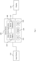
- Figure 1 is a block diagram that includes an example computer system according to certain example embodiments.
- Game device 100 is an example of the computer system 1300 shown in Figure 13 . While the term “game” device is used in connection with certain example embodiments herein, this is done for ease of use and any type of computing device may be used. Indeed, a "game” device as used herein may be a computing device (e.g., a mobile phone, tablet, home computer, etc.) that is being used (or will be used) to play a video game at that time.
- a non-limiting illustrative list of computing devices may include, for example, a smart or mobile device (e.g., a smart phone), a tablet computer, a laptop computer, a desktop computer, a home console system, a video game console system, a home media system, and other computer device types.
- Game devices 100 may include a CPU 102, a GPU 106, and DRAM (dynamic random-access memory) 104.
- CPU 102 and GPU 106 are examples of processor 1302 from Fig. 13 .
- DRAM 104 is an example of memory devices 1304 from Fig. 13 .
- Different types of CPUs, GPUs, DSPs, dedicated hardware accelerators (e.g., ASICs), FPGAs and memory technology may be employed on game device 100.
- Examples of different types of CPUs include an Intel CPU architecture (e.g., x86) and an ARM (Advanced Risk Machine) architecture.
- Examples of different GPUs include discrete GPUs like the NVIDIA V100 (which may include hardware support for matrix multiplications or tensor cores/accelerators) and integrated GPUs that may be found on a system on a chip (SoC). SoCs may combine two or more of the CPU 102, GPU 106 and local memory like registers, shared memory or cache memory (also called static RAM or SRAM) onto a single chip.
- DRAM 104 also called dynamic RAM
- DRAM is usually produced as a separate piece of semiconductor and connected to the SoC through wires.
- the NVIDIA Tegra X1 SoC includes multiple CPUs, a GPU, Northbridge controller, Southbridge controller, and a memory controller all onto a single SoC.
- the processing capabilities provided by the CPU, memory components, GPU, and/or other hardware components that make up a given game device may be different on other game devices.
- Some game devices may be mobile, some may be stationary game consoles, or operate as personal computers (e.g., a desktop or laptop computer system that is used to play video games).
- GPUs may include many processing cores that operate in parallel. Each processing core that is part of the GPU may operate along with corresponding hardware registers that store data therein that are used by the various processing cores.
- the GPU architecture from NVIDIA includes many 32bit, 16bit, and/or 8bit registers that provide data to the processing cores of the GPU.
- the highest bandwidth memory may be available in registers, followed by shared memory, then cache memory, then DRAM.
- the data regarding the datasets that are to be converted may be efficiently loaded into these registers to allow for increased efficiency in converting the datasets to another from (e.g., another resolution).
- the techniques discussed herein may increase the power consumption of the GPU due to using a greater percentage of the processing power that is available to the GPU being used (e.g. up to 80, 90, or 95% or greater).
- a greater percentage of the processing power that is available to the GPU being used e.g. up to 80, 90, or 95% or greater.
- Such techniques may thus allow a user to play a game on a mobile device as they are, for example, commuting home from work. In this mode the user would use the local display on the device (e.g., 540p) for the video game.
- game device 100 stores and executes a video game application program 108. Included in the video game application program are a game engine 110 and a neural network 112.
- the game device 100 may also store image data (e.g., textures) and other types of assets (e.g., sound, text, pre-rendered videos, etc.) that are used by the video game application program 108 and/or game engine 110 to produce or generate content for the video game (or other application) such as, for example, images for the game.
- assets may be included with a video game application program on a CD, DVD, or other physical media, or may be downloaded via a network (e.g., the Internet) as part of, for example, a download package for the video game application program 108.
- a cloud-based system may operate dynamically with respect to the target display that is being used by a user.
- a video game may natively output images in 540p.
- a first user may use the cloud system to receive images that are at 1080p (e.g., upconverted from 540p) and a second user may use the cloud system to receive a different resolution image (e.g., a 720p image, 4k image, or a 1440p image).
- a different resolution image e.g., a 720p image, 4k image, or a 1440p image.
- Each instance of the video game application and/or neural network
- the GPU may instead be (or include) an ASIC or FPGA that operates in a manner similar to the GPU.
- game device 100 may be two or more computer systems.
- the layers for a given pixel may be "fused" together as they remain in the registers during the processing. This is discussed in more detail in connection with Fig. 2 below.
- the activation matrices may remain within internal memory the hardware (e.g., a GPU, CPU, DSP, FPGA, ASIC, etc.) that is performing the matrix operations on the activation matrices.
- data for a given activation matrix may remain within the same semi-conductor hardware (which may be the same silicon for silicon based memory or other material, such as gallium, germanium, etc. for other memory types) while the various layers of a neural network are applied to that activation matrix - e.g., successively transforming the activation matrix over the multiple layers of the neural network.
- a general transform of a layer using a block matrix (with each of the blocks W being a genericp xp matrix) may be present as follows: W 0 ⁇ 0 W a 0 a 1 ⁇ a n
- each block may prevent propagation of the receptive field that would other occur (e.g., in the case of an ordinary CNN).
- the techniques herein may allow for fusing many layers (e.g., as many as desirable) while still maintaining locality of data in question. As the width of the data remains somewhat constant between input and output of each layer, such fused layers may be termed a "Block Tower.”
- the input signal (e.g., which may be an image) may be treated by separable block transforms (or block-convolutional SBTs) in a "translation invariant manner".
- a signal S e.g., a first image
- a signal S' e.g., a second image
- the generated 4x4 blocks of signals S and S' will, most of the time, coincide (excepting the borders of the respective images).
- the output blocks that are generated by applying S and S' through the SBT will be the same.
- the transformed signal will also be the same with just a translation difference between SBT(S) and SBT(S').
- SBTs and/or also block-convolutional SBTs
- the signal is processed in a "convolutional manner" by applying the same calculation while moving the input position (e.g., translating) along the input signal.
- L l 11 ⁇ l p 1 ⁇ ⁇ ⁇ l 1 p ⁇ l pp
- R r 11 ⁇ r p 1 ⁇ ⁇ ⁇ r 1 p ⁇ r pp
- L ⁇ R l 11 R ⁇ l p 1 R ⁇ ⁇ ⁇ l 1 p R ⁇ l pp R
- the left matrix L of dimensions p x p processes all the channels of a given data point, in the same way for each data point. It is of general form, meaning that all of its coefficients can be learned fully independently.
- the right matrix R of dimensions p x p processes all the pixels of a given channel, in the same way for each channel. It is of general form, meaning that all of its coefficients can be learned fully independently.
- the above formulation is symmetric and balanced and may be applied generally in several different instances.
- the form may also be further modified to handle rectangular matrices (e.g., of size p x q) on both the L and R sides.
- the input dimensions of the layer may match with the output dimensions of the previous layer. It will be appreciated, however, that having the values of p and q be multiples of the atomic accelerated hardware matrix multiplication size may provide for increased/efficient use of hardware resources and may, in certain examples, be optimal in terms of speed.
- the block shape and the invariance between data points may advantageously be used to process them together in a single matrix multiplication. Thus providing for efficient use of resources in certain example embodiments.
- sums of separable block transforms may be viewed as an intermediate between a separable transform and a fully connected transform, which may be further tailored for how close to a separable transform or how close to a fully connected transform a particular application needs to be. It is usually presented as a low-rank decomposition in the sense that a fully-connected transform would be of maximal rank p 4 which may be represented with p 2 LXR terms. However, using fewer terms in the sum make it possible to replace the fully-connected layer by a lower ranked transform, with a lower cost in terms of weights and thus storage, training, and/or inference time.
- a potential added benefit of the sum approach can be the performance of the implementation of the inference.
- the code implementing the inference may be strictly limited to matrix multiplications (e.g., with fused multiply and add) executed one after another.
- This type of approach may advantageously allow for operations to be performed without the need to marshal data around, reorganize such data in other forms, or convert the data to other formats.
- This type of approach may also advantageously avoid adding or using unnecessary instructions because the data is already in the right format for each part of the sum.
- the number of LXR sums can be set as a dynamic parameter as the format of the input and output of the sum doesn't change (e.g., it may be assumed to be a 16x16 matrix, such as discussed in connection with the examples herein). This may thus be a way to freely increase the weights and thus the ability to learn/memorize more things while ensuring that the time required for loading the weights remain hidden behind the time it takes to do the matrix multiplications (e.g., which depends on each specific hardware memory bandwidth and matrix multiplication speed).
- the added flexibility can be applied to train an oversized network that may then be compressed by pruning the least necessary elements of each sum while keeping only the "winning ticket” / most relevant aspects obtained at the "lottery" of matrix initializations.
- This dynamic process may help decide, on a content by content basis for each training, how many multiplications are allocated at each layer under a given budget of processing time. Such a determination may be based on knowing a simple model of inference time - which is linear in the number of matrix multiplications. Such aspects may then be combined for deciding the number of layers - (which may be no more than a dozen or so and is usually not a particularly large latent search space).
- a larger number of channels may be employed where several of the separable block towers that are discussed herein may be calculated in parallel from the same input values (e.g., activation matrices) but with different learned weights (L and R matrices).
- L and R matrices Such an approach may be similar in certain respects to grouped channels in Convolutional Neural Networks.
- the output of all block towers can be stored together (e.g., in memory, such as DRAM or cache, for example) and be used together as inputs of another group of separable block towers.
- memory such as DRAM or cache, for example
- Such an implementation may additionally decrease the reliance on DRAM bandwidth (e.g., as data is more quickly accessed through cache memory) compared to an equivalent convolutional neural network architecture.
- a p*p SBT can use more than p*p activations as inputs by fusing several p*p input activations by multiplying each of them with a different p*p weight matrix and adding (e.g., term to term) all results together into a single p*p matrix which becomes the input activation matrix of the SBT.
- This aspect is described in greater detail in connection with Figs. 8C-8E below.
- GPUs are discussed in certain example embodiments herein, it will be appreciated that ASICs and FPGAs may also be designed and used in place of such GPUs in certain example embodiments.
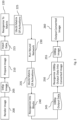
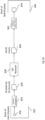
- Figure 2 is a flow chart showing a machine learned upconversion process that converts a 540p image to a 1080p image that may be executed on the computer system of Fig. 1 .
- Figures 3-7 are discussed below and provide additional details regarding certain aspects of the upconversion process shown in Fig. 2 .
- images and pixel data are described in connection with the examples herein, that other types of signals may be used in connection with the techniques herein.
- each "pixel" within the images that are discussed herein may be thought of as data that is being sampled from an overall signal (e.g., the image). Accordingly, techniques for transforming or otherwise converting a source signal (e.g., an image) to a transformed or converted signal (e.g., a higher resolution image) are discussed herein.
- a 540p source image 205 is rendered by game engine 110.
- the source image may come from other sources, such as real cameras, movies, television shows, broadcast television, or the like.
- the techniques herein may be used to transform a source 540p signal that is received for a television program (for example a live broadcast of a sporting event) into a 1080p signal that is then output for display to the user.
- a 540p is discussed in connection with the example in Fig. 2 (and elsewhere herein), the techniques may be applied to images of other sizes.
- the details of the neural network 112 e.g., the coefficients or L and R
- the details of the source and/or converted image change e.g., should the resolution of such images be adjusted.
- a neural network for upconverting to 1080p from 540p will be different than one upconverting from 1080p to 1440p (e.g., 2560 ⁇ 1440). It will also be appreciated that while the example shown in Figs.
- 3-7 relates to transforming a 540p image to a 1080p image
- the techniques herein may be applied to other image sizes (e.g., 720p to 1080p; 480p to 1080p, 1080p to 1440p, 1080p to 4k/3840x2160, 720p to 4k, etc.).
- the initial image may be rendered or otherwise generated with motion vector information and/or depth information (e.g., z-buffer data). This information may be used to improve the resulting converting image quality. Such information may be, in certain example embodiments, added to the activation matrix that is created based on each pixel block.
- upscaling ratios that are not integers (or not the same ratio horizontally and vertically) may also be performed in accordance with the techniques discussed herein.
- Additional ratios such as, for example, 7/3 (e.g., which may correspond to converting from 1920x1080 to 4480x2520) are also possible in accordance with certain example embodiments.
- a source image may be divided into 3x3 blocks (with context data added thereto) and trained to output 7x7 blocks (which would still fit into the 16x16 output block that is discussed herein).
- applications that that output images in resolutions that are not as common now may be modified.
- the techniques herein may use, for example, alternative ratios to handle upscaling. For example, a horizontal upscaling ratio of 8/7 (which may then be multiplied by some integer ratio) may be used in certain example embodiments to compensate or address analog TV anamorphic deformation.
- a 540p image 205 is produced (e.g., rendered) by a game engine or the like at step 200. That image is then prepared at step 210.
- This aspect of the process is described in greater detail in connection with Fig. 3 and involves dividing the image into separate input channels or input data 215.
- the input data 215 may be stored to registers (e.g., 16bit registers) of GPU 106 at this point. Once the input data 215 is generated, it is then stored to registers of the GPU.
- the input data 215 (or matrix of activations 225) may remain within the registers (or other internal memory) over the course of being applied against the neural network.
- This type of implementation advantageously allows the (relatively) slow DRAM 104 in system 100 to be bypassed during the processing that is performed by the neural network (e.g., where the multiple matrix of activations across the image are processed by the GPU). This is facilitated by forming the data to fit within the registers and thus allowing for more effective use of the massively parallel processing that is provided by the GPU 106.
- other types of hardware besides GPUs may be employed for handling the translation of the input data 215 into the 1080p output data 245.
- on-chip memory e.g., registers on a GPU, or SRAM FPGAs that handle deep learning applications. Accordingly, once the input data 215 is placed into the registers (or similar fast memory) it may remain there until the 1080p output data 245 is generated (or the final matrix of activations is generated) and used to construct the final converted image (which may occur in DRAM).
- the input data 215 is then reorganized into a matrix at step 220 to produce a 16x16 matrix of activations 225. This step is discussed in greater detail in connection with Fig. 4 .
- the initial matrix of activations 225 is run through the trained neural network 112 at step 230 to produce a 16x16 matrix of activations 235 that have been transformed by the neural network 112. As discussed herein, this may involve applying separable block transforms to the matrix of activations. This aspect of the process is discussed in greater detail in Fig. 5 .
- the 1080p output data 245 is then reorganized into a 1080p image 255 that is output to display 116 at step 260.
- This aspect of the process is described in greater detail in Fig. 7 .
- the processing that is shown between step 220 and 250 may occur entirely in the registers of the GPU (or other internal memory) without the need to transfer data to DRAM (or other relatively “slow” memory).
- a given matrix of activations 225 may remain stored within the same semi-conductor hardware (e.g., the same register or location in memory) while it is being run through the neural network.
- Such processing may be applied to each matrix that is generated for a corresponding pixel block of an image (or other signal), which may then be concurrently executed across plurality hardware processors of, for example, a GPU (or other hardware resources).
- Figure 3 is a flow chart showing an expanded view of the Prepare Image portion of the machine learned upconversion process of Fig. 2 .
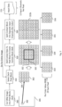
- the 540p image 205 that is output from the game engine 110 is cut or divided into 4x4 pixel blocks at step 300.
- Block 302 represents one of the pixel blocks from the image and 304 is one pixel within that block.
- Each pixel may be represented by different color values in RGB (described in greater detail in step 330).
- RGB described in greater detail in step 330.
- color values e.g., RGB values
- color information may be processed/provided by using YUV or YCoCg formats.
- the luminance (Y) channel may be used with the techniques discussed herein and thus processed (e.g., upscaled) using Neural Networks.
- block sizes other than 4x4 may be used.
- 8x2 pixel blocks may be used in certain example embodiments.
- the size of the pixel block may be advantageously determined based on, or a multiple of, the dimensions of the hardware being used for the matrix multiplication.
- 4x4 or 8x2 blocks may be initially selected. Such sizes may advantageously allow for separately processing the pixels along one dimension of the matrix while processing the channels along the other dimension.
- Selection of a block size may also be based on the amount of available fast memory in a system (e.g., registers, etc.). Keeping the blocks and corresponding data for the matrices in fast memory during the neural network processing advantageously may facilitate increased performance (e.g., to allow real-time or runtime image conversion). Thus, a 4x4 block size may be appropriate for certain types of hardware, but other block sizes are also contemplated and may be used in connection with the techniques discussed herein.
- each block from the original 540p image 205 is selected at 310.
- the subsequent processing for all of the pixel blocks may be performed in parallel by using, for example, the hardware resources of a GPU or other processor.
- multiple groups may be processed in sequence. For example, a first group of the pixel blocks may be processed in parallel (e.g., 15,000) and then another group (the remaining 15,000) may be processed.
- the processing for all of the blocks may, from the perspective of a user, still be performed in parallel.
- context data is added to the 4x4 pixel block to create an 8x8 context block 322.
- the context data may be based on, derived, or a function of the pixel values of the pixels in the image that surround a given pixel block.
- the pixel data that is used for the context block may remain unchanged from the pixel outside of the 4x4 pixel block.
- other context block sizes either absolute or relative
- pixel data may be selected along the horizontal and/or vertical axes with discounting those along a diagonal axis.
- one pixel along the diagonal may be used, while two (or more) along the horizontal or vertical may be used within the context block.
- multi-resolution data may be included within the context block to increase the receptive field along the directions of "slightly tilted lines" which aliasing may extend far away from the block.
- one layer could contain 4x4 blocks calculated as the average of the 8x8 context block, then a 4x4 block calculated as the average of the 16x16 context block, etc. Such data may help to increase the receptive field with a limited cost in terms of number of inputs.
- the context block 322b is split into four separate input channels 333, 334, 335, and 336.
- the numbers represented by each of the input channels shows the makeup of that particular channel. Accordingly, each 1 that is shown in 322b in Fig. 3 is used to form input channel 333 and each 2 is used of form input channel 334, and so on.
- Each of the numbers represents a value for one of the RGB values for the correspondingly pixel.
- each context block 332 is repeated or otherwise performed for each value of Red (R), Green (G), and Blue (B) (or the context block simply stores 3 values per pixel). Accordingly, there are 12 input channels per pixel block that are created as a result of the prepare image step 210.
- the multiple pixel blocks may be processed in parallel in certain example embodiments.
- signal data for a source signal may be cut or split into at least two blocks. In certain examples, such blocks may then be processed independently by using the SBTs discussed herein.
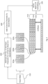
- Figure 4 is a flow chart showing an expanded view of the Reorganize To Matrix portion of the machine-learned upconversion process of Fig. 2 .
- the input data 215 for each pixel block is reorganized into a single 16x16 matrix 225 at step 410.
- the values of input channel 333a e.g., that has the red color values of "1" pixel value that is in the context block 322b
- the values of input channel 333b (the blue color value of that same "1" pixel from the context block) are inserted to row 414.
- the values of input channel 333c (the green color value of that same "1" pixel from the context block) are inserted to row 416.
- the 16x16 matrix of activations 225 is populated with values from the sampled pixels of the source image (e.g., a source signal).
- the resulting 16x16 matrix may include data for a single pixel within multiple rows.
- the pattern of data for each of the pixels used to feed rows 412, 414, and 416 is superposable from one pixel to the next.
- the data may be inserted into a matrix on a column by column basis instead of row-by-row basis as is shown in Fig. 4 . Accordingly, columns may be substituted for the rows mentioned herein in certain example embodiments.
- Examples of superposable patterns may include, for example, two horizontally located neighbor blocks of 4x4 pixels (e.g., after 4 pixels of horizontal translation). As another example, any two rows (e.g., of 4x1 pixels) within a 4x4 block of pixels may be superposable. Similarly, a row of 4x1 pixels is superposable to a column of 1x4 pixels (after a 90° rotation).
- the following pattern of blocks are superposable. Specifically, the pattern of X's in the below table (accounting for rotation and symmetry) are superposable with the pattern of samples represented by the Y's. Table 2 X Y Y Y X Y X X
- At least two of the rows (or columns) in an initial activation matrix may correspond to similarly organized or structured data from each sample that is taken from the underlying source.
- the similarly organized or structured data may be individual pixels (e.g., where multiple channels are used per pixel) or groups of pixels following the same shape but at different positions in the image.
- at least two of the rows or columns of the activation matrix may be generated based on a common pattern of data from each sample in the underlying source signal.
- the remaining 4 rows of the 16 row matrix are set to zero at step 420 (or otherwise set to values such they are ignored during the matrix processing) to create matrix of activations 225 that will then be subjected to the neural network processing.
- all 16 may be populated with data.
- the 4 additional rows (or the "extra" rows that do not have the initial color information) may be populated with additional information.
- the game engine 110 may supply depth information regarding objects or other aspects of the image in question. This information may be incorporated into the additional rows of the 16x16 matrix.
- motion information regarding objects or other aspects of the image may be supplied from game engine 110 and incorporated into the 16x16 matrix.
- Figure 5 is a flow chart showing an expanded view of the Run Neural Network portion of the machine learned upconversion process of Fig. 2 .
- the running of the neural network against the matrix of activations may include applying separable block transforms that make use of the LXR operation discussed herein.
- the matrix of activations 225 is run through the neural network 112. An example of how such neural networks may be trained is discussed in connection with Fig. 9 .
- the output of such training may be a matrix of coefficients (L and R) that have been "trained" on example training datasets.
- the matrix of activations 225 that is generated from the input channels is run through a separable block transform at step 410.
- the equation that represents this process is illustrated in Fig. 5 with L and R being 16x16 matrices (e.g., each with 256 coefficients that in the 16x16 matrix) that have been generated using the training system discussed in Fig. 9 .
- L is a 16x16 pixel-wise matrix (or other sample-wise dependent aspect) and is multiplied on the Left. This applies a linear transform to all channel values of each activation pixel (e.g., each piece of sample data), which may be each column in the activation matrix, independently from the pixel position (e.g., the same transform for each pixel).
- an activation function 420 is applied. This may be ReLU (rectified linear unit) - e.g., if value is negative, set to 0. If the value is positive, leave it as is.
- Other types of activation functions e.g., a linear function, a tanh function, a binary function, a sigmoid function, different versions of ReLU such as leaky, parameter based, and ELUs, Swish, etc.
- image processing may use one type of activation function and natural language processing may use another.
- the type of activation function that is used on a given layer may differentiate between the layers.
- an ReLU activation function may be used in layers 1 through n-1 (where n in the number of layers), with a Sigmoid activation function being used at the n th (e.g., last) layer.
- This processing produces a transformed matrix of activations 425. That is represented as X n +1 .
- the number of layers may be dynamically controlled by the neural network 112, the video game application 108 (or other application, such as the operating system, that is handling the conversion process). For example, the system may determine the amount of time that it is taking process images and add or remove layers based on such a determination. For example, if the conversion process is taking too long for real-time processing, then a pre-trained network with one or more fewer layers may be used). Such techniques may be beneficial to account for different types of hardware resources that are being used by a given computing device.
- Result[i][j] is the coefficient at the i th column and j th row (being initialized to 0 before the loop).
- a separable block transform (SBT) at 410 may be viewed as an alternative to using a fully connected / linear layer.
- a linear layer e.g., a fully-connected layer
- a linear layer is a matrix multiplication of an unstructured vector of input activations given an unstructured vector of output activations.
- a 256 ⁇ 256 linear layer can be represented by a 256 ⁇ 256 matrix of independent weights and applied against 256 unstructured independent inputs.
- a potential downside to this number of coefficients within a layer is that it may have too many coefficients (e.g., degrees of freedom) to train or calculate at runtime (e.g., to provide for real-time image processing).
- the L i,j n matrix is set to a special form where each coefficient l i,j of coordinates ij is set to 1 and all other coefficients are set to zero.
- the L n X n product is then the result of: extracting the i th line of the matrix X n ; and re-positioning it at the j th line while the rest is set to zero.
- each of the resulting j th line of X n+1 is a general linear combination of all the lines and thus coefficients of the X n .
- SBTs may provide one or more of the following advantages:
- SBTs may be gradually pruned by removing individual LXR terms (e.g., those that contribute the least to the quality of the result).
- Each removed LXR term may reduce the complexity of the training and runtime calculations, the total number of weights to be stored and transmitted, and the remaining learning cost.
- a sum of less than 8 LXR terms will cost less multiplications than a linear layer.
- a sum of k LXR terms will cost k*2 13 multiplications and thus cost less than a linear layer if k ⁇ 2 3 (e.g., 8).
- a benefit of SBT compared to linear layers may include allowing for the reduction of the number of weights (e.g., in a kind of weight reuse scheme). It will be appreciated decreasing the number of weights may have an impact (e.g., perhaps significantly so) on performance because it may reduce the memory traffic for handling the weights. Due to this more space in memory can be devoted to activations.
- the pressure on memory may also be alleviated (e.g., decreased) - e.g., in the form of external memory bandwidth or internal memory size.
- SBTs may also be used to replace larger linear layers (e.g., 1024 to 1024, such as those used in natural language processing) with a 32x32 SBT layer. This would allow for a smaller number of weights while maintaining an acceptable level of quality. Accordingly, the technical implementation of the SBT techniques discussed herein may be used in a variety of different applications and scenarios to achieved increased efficiency with little or no (e.g., perceived) loss in the quality of the transformed data.
- the size of a sum can be different for each layer, learnt by trial and error and/or by global pruning.
- a smaller version of the SBT network can be trained through distillation from a trained bigger version of the SBT network.
- Figure 6 is a flow chart showing an expanded view of the Reorganize Into Blocks portion of the machine learned upconversion process of Fig. 2 .
- the 16x16 matrix of activations 235 Once the 16x16 matrix of activations 235 has been generated by running it through the neural network 112, it is then reconverted back into the form of multiple channels. Specifically, each row (or more specifically the first 12 rows as the last 4 are all zeroed out) of the matrix of activations 235 is reorganized into a corresponding block of one output channel.
- the first row of the matrix of activations 235 is converted back into the first block 602a (e.g. the red values of the top-left sub-pixels) of the 1080p output data 245.
- the second row of the matrix of activations 235 is converted back into the second block 602b (e.g., the green value of the top-left sub-pixels of that same channel) of the 1080 output data 245, etc. All 12 blocks (4 sub-pixel channels per block * 3 channels per color value) of the corresponding 12 rows of the matrix of activations 235 thus create the 12 output channels of the 1080poutput data 245.
- Figure 7 is a flow chart showing an expanded view of the Reorganize 1080p Output Data Into Converted Image portion of the machine learned upconversion process of Fig. 2 .
- the 1080p output data 245 e.g., the 12 output channels of 4x4 blocks
- Fig. 7 illustrates an example how the values from the blocks (e.g., illustrated the highlighted value 713 from block 602) may be used to generate a corresponding pixel value 714 (also highlighted) in the pixel block 712. This includes combining the color values to create each pixel.
- the Red, Green, and Blue values of 713 from each of the Red (e.g., from 602a), Green (e.g., from 602b), and Blue blocks 602 will be used to generate the RGB value for pixel 714 in pixel block 712.
- the remaining 63 pixels in the 8x8 block will be generated in a similar manner.
- the resulting 8x8 pixel block 712 is then positioned within the overall 1080p image 255.
- This process of assembling 8x8 pixel blocks is repeated (e.g., in parallel) for each of the 1080p output data 245 that has been generated for a single (original) 540p image.
- a 1080p image 255 is assembled at 720.
- Each of the 8x8 pixel blocks is positioned within the overall image (e.g., based on the order in which the source image was processed). Thus, if the source image is processed from left to right and top to bottom, then the output image is constructed in a similar manner.
- position data for each pixel block may be stored as, for example, metadata for each of the created input channels 215 when it is originally created to determine where the 8x8 pixel block should be positioned.
- the 1080p image 255 may then be output at 260 or otherwise stored (e.g., into a frame buffer) for eventual display on display device 116.
- Figures 8A-8B shows an example image 802 that is 128x128 pixels.
- Image 802 has been applied to a neural network 803, which has been trained according to the techniques discussed herein (e.g., in connection with Fig. 10 ). After applying image 802 to neural network 803, upscaled image 804 is generated.
- Image 804 is version of image 802 that has been upscaled to 256 ⁇ 256 pixels.
- Figure 8B includes versions of the images from Fig. 8A that have been "zoomed” in to create side-by-side 512x512 pixels versions of those images.
- image 822 which is a zoomed in version of image 802
- image 824 which is the zoomed in version of image 804. It will be appreciated that the images shown in Figs. 8A and 8B are shown by way of example.
- Figure 8C shows an example block diagram view of a single "block tower" according to certain example embodiments.
- Figures 8D and 8E are example block diagrams that show how several block towers may be used according to certain example embodiments.
- Figure 8C shows a block diagram that corresponds, in certain respects, to the examples discussed in connection with Figures 2-7 .
- a block of pixels 830 is selected from a source image 832.
- a 16x16 activation matrix 836 is prepared at 834 (e.g., as described in connection with Figs. 3 and 4 ).
- Activation matrix 836 is then run through the SBT network 838 (e.g., as shown in Fig. 5 ) to create output matrix 840.
- an output pixel block 844 is created at 842 (e.g., as shown in Fig. 6 and 7 ) and then placed into the converted image 846.
- two 16 ⁇ 16 SBT towers e.g., L&R matrices
- activation matrices of 16 channels may be used.
- the requirement of having more and more local fast memory may be (at least partly) addressed while also still benefiting from the increased expressivity (higher degrees of freedom) that using an increased number of channels can provide (e.g., 32 or 64, etc.).
- SBTs may be processed sequentially or processed in parallel.
- a given activation matrix may be run through multiple different SBTs and the outputs combined or used together in one of multiple different ways.
- FIG. 8D shows a block diagram of a summing example for using several SBTs.
- an activation matrix 836 is created from a block with the source image.
- that activation matrix is applied to multiple different SBT networks.
- activation matrix 836 is applied to SBT 852A, 852B, 852C, and 852D.
- the same activation matrix (which is derived from the same underlying pixel block) may be processed by separate SBT (e.g., L&R matrices). Such processing may be performed sequentially, in parallel or some combination thereof (e.g., two at a time).
- Each SBT processes activation matrix 836 differently to create four (presumably) different output matrices - 854A, 854B, 854C, and 854D. These four outputs may then be summed, term to term, to create a final (e.g., 16 ⁇ 16) output matrix that is then processed as is discussed in connection with Fig. 8C .
- Figure 8E is a block diagram of an alternative example for using several SBTs. This example is the same as that shown in Fig. 8D , except instead of summing the results from the several SBTs, the resulting outputs may be stacked or aggregated together into a larger matrix at 860. This type of implementation may be useful to, for example, handle bigger output blocks 862 of the output image 864 which may naturally benefit from a higher number of activations in the output activation matrix.
- Such techniques may be similar or compared to, for example, grouping channels/grouped convolutions as used in various CNN architectures (e.g., AlexNet, MobileNet, etc.).
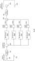
- Figure 9 is a block diagram that includes an example training computer system 900 according to certain example embodiments.
- Training computer system 900 is an example of computer system 1300 that is shown in Figure 13 .
- computer system 900 and computer system 100 may be the same system (e.g., the system that is used to play a video game also may be configured to train a neural network for that video game).
- System 900 includes a dataset preparation module 902 that is used for preparing images (e.g. 1080p images) that are provided from a training set database 906.
- the images are prepared and then used to train a neural network (e.g., to determine the coefficients of L & R, including each layer of sums of L & R transforms, that are discussed herein) via the neural network trainer module 904.
- the neural network trainer module 904 generates one or more trained neural networks that are stored into database 908.
- Trained neural networks 908 may then be communicated via a network 912 (e.g., the Internet) or via physical media (like game cartridges) to various game devices 1, 2, 3, 4, 5, etc. (each of which may be an example of game device 100).
- one or more trained neural networks may be delivered along with a game that is acquired by a user.
- a user may download a game from an online store or the like and one of the components of the game may be a neural network for processing images produced by the game.
- games that are provided on cartridges or other physical media may include one or more neural networks that can be used by the user to transform images produced by the game.
- multiple neural networks may be provided with the same instance of a game (e.g., an individual download or specific physical media instance) to allow for the game to output to different types of displays (e.g., 1080p in one instance, 1440p in another, 4k in another, etc.).
- game device 1 may receive and use a neural network that is different than a neural network that is received and used by game devices 2, 3, 4, and 5.
- each game (or more generally each application) may have a corresponding neural network (or multiple neural networks) that has been generated (e.g., by system 900) for that game.
- game devices may store multiple different neural networks and use different such networks based on the game (or type of game) that is being played on the corresponding game device.
- multiple games may share or use the same neural network.
- one neural network may be generated for first person shooter type games, another for strategy games, etc.
- game may be group based on their "type.” Such type classifications may be based on the genre of game or may be based on another criteria, such as the type of rendering engine that the game uses to generate images therein.
- the game engine (or other service that is providing converting functionality to the game engine) may dynamically decide to select one neural network among a selection of them depending on the remaining time available to "prepare the current video frame". If the frame was rendered fast, it may have more time to be upscaled with a high quality and slow neural network (e.g., one that includes additional layers), but if the frame used up more of the typically available 16ms (for both rendering of the frame and subsequently upscaling images at 60 frames per second), the engine could select a faster neural network (e.g., one with less layers), although not providing as high image quality as the slower ones. Such a determination may be made through a "testing" phase of a video game application program (e.g., where the game engine produces a number of example images) and/or may be performed during normal gameplay.
- a testing phase of a video game application program e.g., where the game engine produces a number of example images
- training datasets 906 includes multiple datasets that are used as the "target.”
- a neural network is to be generated to convert 540p images into 1080p images, this may include different 1080p images that will be used to generate the neural network.
- the type of 1080p images may be selected according the particular use case.
- the images may be 1080p images that have been generated by game engines natively.
- the images may be from the same game engine or game for which the neural network is being used.
- game A may include a game engine that has the ability to generate 1080p images. This may be beneficial because another version of game A may be produced that generates game images in 540p.
- the game engine of game A may thus be used to populate the 1080p images for training dataset(s) that will be used to train a neural network that can be used in conjunction with the other version of game A (e.g., to thereby allow it to output 1080p images - even when that version was not originally designed for such images).
- the target images should be of high visual quality.
- Such images may be prepared in advance and would not need to be rendered in "real-time" (e.g., at 30 or 60 frames per second).
- Such images may be rendered as sharp and clean and using high-end anti-aliasing settings.
- the images may be generated from the same game or game engine as the one for which the trained network will be used. In such a scenario the statistics of the training data may more closely match the statistics of the runtime data and thus the generated neural network may be better optimized for such a game.
- a default or "general" selection of images may be used. Such an implementation may provide a good cross section across multiple games.
- the target images may be selected that are a relatively good or high quality and have a relatively good level of diversity and sharpness (e.g., without relatively visible aliasing). This type of approach may allow for using the full spectrum's available spatial frequencies.
- artificially generated images can be used where such images are rendered in pairs of low and high resolution images.
- different types of images e.g., pixel art
- upscaled e.g., where such images may suffer from the lack of available high resolution images and may not visually look as good when upscaled through use of general purpose neural networks.
- the training computer system may be implemented in a cloud-based computing system.
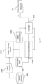
- Figure 10 is a flow chart showing a process that may be implemented on the system shown in Fig. 9 for training a neural network that may be used in connection with certain example embodiments, including the process shown in Fig. 2 .
- the training datasets 906 a plurality of target images or training images are selected.
- the images may be a collection of 1080p images 1000.
- each of the images within this collection is passed to the Dataset Prep Module 902 for preparing the training dataset that will be used to train a neural network.
- the first is preparing the 1080p images into 1080p output data 1006. This aspect is discussed in Fig. 11 .
- the second is preparing 540p images (or other images that will be used as the source images) into 540p input data 1004. This aspect is discussed in Fig. 12 .
- the processing discussed in Figs. 11 and 12 may be repeated or otherwise performed for each image that is used within the training dataset.
- the images may be streamed (e.g. the preparation process may proceed concurrently with the training process).
- the preparation of the images may be batched (e.g., 256 or cropped sub-parts of such images may be prepared in a training batch before being used as data for one step within the training process of a neural network).
- the 540p input data 1004 is then used to train the neural network at 1008 until the results of the training converges coverage at 1010 close enough to the 1080p output data 1006.
- the set of coefficients e.g., L & R
- the training process is repeated until this convergence is reached (e.g., within a threshold error value or because there has not been any decrease of the error value for more than a threshold number of iterations).
- the trained neural network weights (e.g., the coefficients of the L & R matrices, which may be called the trained neural network herein) 910 may be stored to the database within system 900 and/or communicated to other computer systems (e.g., game devices 1, 2, 3, 4, 5, etc.).
- the techniques associated with SBT networks may allow for a favorable environment for pruning as each individual sum element (e.g., LXR) can be removed without interfering with the rest of the architecture - even in case of residual connections because no other connections rely directly on this specific term.
- each LXR term can be thought of as a single "branch" of the architecture which can be removed without disturbing the rest of the network.
- This type of approach may be advantageous because removing channels in a residual network may have negative results in terms of a quality and/or performance as each channel is generally used as input to a following layer downstream.
- the determination of which LXR term(s) (e.g., each SBT term) to remove may be based on calculating the global loss with and without each LXR term (e.g., the result of the calculation of L*X*R as an individual term, or part of the summation of LXR products) and then removing those terms that have the least impact to the global loss.
- LXR term(s) e.g., each SBT term
- prune may be based on calculating the global loss with and without each LXR term (e.g., the result of the calculation of L*X*R as an individual term, or part of the summation of LXR products) and then removing those terms that have the least impact to the global loss.
- those terms below a certain threshold may be removed or those terms in the bottom x% (e.g., 1% or 5% may be removed)
- the process can re-start until reaching a given size or error goal.
- pruning may be performed for an SBT network by calculating or otherwise determining the gradient of the loss for each SBT term and removing the SBT term which has the lowest gradient (or those terms that are in a bottom percentile).
- Figure 11 is a flow chart showing an expanded view of how 1080p image data is prepared as part of the neural network training process that is shown in Fig. 10 .
- Each 1080p image 1000 is cut into 8x8 pixel blocks at 1110.
- Each pixel block (1122) is then selected at 1120.
- the pixel blocks are then split at 1130.
- Fig. 11 illustrates pixel block 1122 being split into separate input channels for the step at 1130.
- the pixel values of the corresponding numbers in the pixel block 1122 are assigned to the corresponding input channel.
- Each channel includes 3 separate input channels per RGB value of the source pixel.
- 12 input channels are created (e.g., 1132, 1134, 1136, 1138, each with RGB, etc.) and used as the 1080p output data. This process is repeated for each of the 1080p images to create plural 1080p output data that will be used during the training process for the neural network (e.g., to determine when the neural network has converged).
- Figure 12 is a flow chart showing an expanded view of how 540p input data is prepared as part of the neural network training process that is shown in Fig. 10 .
- the 540p input data 1004 is prepared from the 1080p output data 1006 that is produced as shown in Fig. 11 . Specifically, at 1210, one of the output channels from the 1080p output data 1006 is used to create a single 540p image 1212.
- each 4x4 pixel block (1214) (e.g., which may correspond to the color channels of 1132 in Fig. 11 ) within the created 540p image is then selected at 1220.
- context data is then added around the 4x4 pixel block to create an 8x8 context block 1232a.
- the context data may be derived in a manner similar to that described above in connection with Fig. 2 .
- the context block 1232b (which may be the same as the context block 1232a, but with a change in indexing of activations) is split into 4 separate input channels, with each input channel including 3 channels for the respective RGB values for the pixels included in the channels.
- the input channels are created such that the 1s in 1232b are mapped into channel 1242, and the 2s are mapped to channel 1244, etc.
- the 12 resulting input channels make up the 540p input data 1004 (e.g., a 16x16 matrix) that will be used to train the neural network during the training process that is discussed in connection with Fig. 10 .
- the lower resolution input may be generated by down-sampling the high resolution input through point sampling (e.g., nearest neighbor).
- point sampling e.g., nearest neighbor
- other down-sampling methods may be used in other example implementations.
- images that rendered fast (e.g., at 60 fps or the like) by a real-time game engine may naturally be similar to images resulting from point sampled down-sampling because each pixel value is calculated independently from its neighboring pixels. Accordingly, training a neural network by using point sampled data may be likely to better fit upscaling game engine outputs. It may also help game engines in certain example embodiments to run faster because additional costly anti-aliasing efforts may be skipped during the traditional rendering phase. Rather, such anti-aliasing may be handled more efficiently by the example neural network techniques discussed herein.
- Point sampling as part of the down-sample for the training process may provide additional benefits.
- a critically sampled signal is a discrete signal coming from a continuous signal where frequencies reach the maximum admissible frequencies according to the Shannon-Nyquist sampling theorem (i.e., signal frequencies should not go beyond half of a sampling frequency f) while still being able to be perfectly reconstruct the continuous signal from the discrete signal without any loss.
- the significant frequencies of the spectrum may be mainly located in the low part of the spectrum (between 0 and f/4) or the high part (between f/4 and f/2).
- high frequencies between f/4 and f/2 are not removed but rather may be "folded" into the low part of the spectrum (between 0 and f/4, which becomes between 0 and f'/2 in the newly down-sampled signal).
- Neural networks can then take advantage of the context information to reconstruct the signal in a non-linear (e.g., a learned) way. For example, they learn whether the spectrum comes from actual low frequencies and should thus be reconstructed as low frequencies of the up-sampled signal or comes from the high part of the spectrum and should thus be reconstructed as high frequencies of the up-sampled signal.
- a non-linear e.g., a learned
- the use of down-sampling with point-sampling at the training stage can pack up to twice as much information in the same storage space compared to a conventional sampling approach.
- the high-resolution images used during training may be prepared following similar techniques to those discussed above (e.g., using frequencies beyond the sampling limit). Providing that the images won't be resampled inappropriately later on through the display process.
- the processing discussed above generally relates to data (e.g., signals) in two dimensions (e.g., images).
- the techniques herein e.g., the use of SBT's
- data or signals of other dimensions for example, 1D (e.g., speech recognition, anomaly detection on time series, etc...) and 3D (e.g., video, 3D textures) signals.
- 1D e.g., speech recognition, anomaly detection on time series, etc
- 3D e.g., video, 3D textures
- the techniques may also be applied in other types of 2D domains such as, for example, image classification, object detection and image segmentation, face tracking, style transfer, posture estimation, etc.
- the processing discussed in connection with Figs. 2 and 9 relates to upconverting images from 540p to 1080.
- the techniques discussed herein may be used in other scenarios including: 1) converting to different resolutions than those discussed (e.g., from 480p to 720p or 1080p and variations thereof, etc.), 2) downconverting images to a different resolution, 3) converting images without changes in resolution; 4) images with other values for how the image is represented (e.g., grayscale).
- the techniques herein may be applied to processing images (e.g., in real-time and/or during runtime of an application/video game) to provide anti-aliasing capability.
- the size of the image before and after remains the same - but with anti-aliasing applied to the final image.
- Training for such a process may proceed by taking relatively low-quality images (e.g., those rendered without anti-aliasing) and those rendered with high quality anti-aliasing (or a level of anti-aliasing that is desirable for a given application or use) and training a neural network (e.g. L&R as discussed above).
- fixed resolution applications may include denoising (e.g., in conjunction with a ray-tracing process that is used by a rendering engine in a game engine).
- denoising e.g., in conjunction with a ray-tracing process that is used by a rendering engine in a game engine.
- deconvolution for example in the context of deblurring images and the like.
- each image is divided into blocks (e.g., 4x4) and context data is added to those blocks to create an 8x8 context block.
- the subsequent context block is then split into 4 input channels, with 3 channel colors per channel to create 12 input channels.
- Those 12 input channels are then reorganized into a 16x16 matrix of activations in a manner similar to that shown in Fig. 4 .
- the matrix of activations is then run through the neural network where the separable block transform is performed with the L and R matrices that have been developed via the above discussed training.
- the first 3 (or any 3, which may be based on training) output channels (e.g., the RGB values that correspond to the "1" pixels) are reorganized into their respective blocks and combined into a single 4x4 block. This process is repeated for each of the original 4x4 blocks that were taken from the source image. The transformed blocks are combined together to thereby create the resulting image that may then be output.
- a classification process e.g., finding/identifying an object in an image
- a given image may be split into 4x4 pixel blocks and a sliding 3x3 block kernel transform can be applied to all of the image blocks.
- the kernel may have other sizes (e.g., kernel can have other sizes, like 2x2, or separable with 3x1 followed by 1x3).
- the 8 blocks that surround a given block e.g., 3x3 surrounding blocks
- the block itself are processed with SBT and the results are summed into a single target block (e.g., that corresponds to the position of the selected block).
- the 16x16 block values are summed term to term.
- one or more block-convolutional layers can be alternated with reduction layers of various types. For example, max or average pooling may be used or down sampling with stride or other similar techniques may be used.
- the neural network may include one or more normalization layers. Such layers may be generated by using batch normalization, weight normalization, layer normalization, group normalization, instance normalization, batch-instance normalization, etc.
- layer fusion can be implemented between successive block-convolutional layers to further reduce the pressure on memory bandwidth (e.g., DRAM).
- memory bandwidth e.g., DRAM
- residual connections e.g., a skip connection
- SBT layers residual connections
- the output image may have two times less blocks in horizontal and vertical dimensions.
- the final image may end up with only one block of 16x16 activations.
- the final block can then be used as an input of a traditional fully-connected layer with the output neurons count matching a number of classes (e.g., for classification applications).
- the output classes may be put into the diagonal coefficients of the matrix. This may let the SBT training learn the equivalent of a fully-connected layer in the L and/or R matrices (even with a single LXR element without a sum). More generally, for a number of classes above 16 and below or equal to 256, an SBT with up to 256 sum elements may be used (which becomes equivalent to a fully connected network of 256 neurons). For a number of classes below 256, sums of fewer than 256 LXR terms are likely to fit the problem well and the optimal number of terms may be found. In certain example embodiments, finding the optimal number of terms may be accomplished by pruning LXR sums.
- finding the optimal number of terms may be accomplished by Singular Value Decomposition (or matrix spectral decomposition) of a trained fully-connected layer to determine the number of "significant" singular values (e.g., those not close to zero) and training the corresponding number of LXR terms (for example, 2 LXR terms for 32 significant singular values).
- each group of 2x2 blocks is reduced into a single block by calculating the average (or the max) of corresponding terms.
- block convolution layers may be alternated with block pooling layers (e.g., several times) and the final image may end up with only one block of 16x16 activations. Similar to the stride implementation, this final 16x16 activation may be used as an input of a traditional fully-connected layer with the output neurons count matching a desired number of classes (e.g., for classification applications).
- FP32 costs more than FP16 which costs more than INT8.
- using INT8 may provide an attractive sweet-spot in terms the tradeoffs between speed/quality and/or cost/quality.
- low and high resolution output from a game engine may be used for training purposes (e.g., instead of down sampling).
- such an approach may result in discrepancies and/or may impair training.
- the images produced in such a manner may alleviate these problems if the rendering engine that produces the images is "resolution independent.”
- the conversion techniques discussed herein may operate in a two-step process.
- a first image e.g., a 1080p image
- an 8k image Such a process may include first converting 1080p image to a 4k image and then converting the resulting 4k image to an 8k image in accordance with the techniques discussed herein.
- Figure 13 is a block diagram of an example computing device 1300 (which may also be referred to, for example, as a "computing device,” "computer system,” or “computing system”) according to some embodiments.
- the computing device 1300 includes one or more of the following: one or more processors 1302; one or more memory devices 1304; one or more network interface devices 1306; one or more display interfaces 1308; and one or more user input adapters 1310. Additionally, in some embodiments, the computing device 1300 is connected to or includes one or more display devices 1312. Additionally, in some embodiments, the computing device 1300 is connected to or includes one or more input devices 1314. In some embodiments, computing device 1300 may be connected to one or more external devices 1316.
- these elements are hardware devices (for example, electronic circuits or combinations of circuits) that are configured to perform various different functions for and/or in conjunction with the computing device 1300.
- each or any of the processors 1302 is or includes, for example, a single- or multi-core processor, a microprocessor (e.g., which may be referred to as a central processing unit or CPU), a digital signal processor (DSP), a microprocessor in association with a DSP core, an Application Specific Integrated Circuit (ASIC), a Field Programmable Gate Array (FPGA) circuit, or a system-on-a-chip (SOC) (e.g., an integrated circuit that includes, for example, a CPU, a GPU, and other hardware components such as memory and/or a memory controller (e.g., Northbridge), I/O controller (e.g., Southbridge), networking interfaces, and the like).
- a microprocessor e.g., which may be referred to as a central processing unit or CPU
- DSP digital signal processor
- ASIC Application Specific Integrated Circuit
- FPGA Field Programmable Gate Array
- SOC system-on-a-chip
- each or any of the processors 1302 uses an instruction set architecture such as x86 or Advanced RISC Machine (ARM).
- each or any of the processors 1302 is or includes, for example, a graphical processing unit (GPU), which may be an electronic circuit designed to generate images and the like.
- GPU graphical processing unit
- One or more of the processors 1302 may be referred to as hardware processors and one or more of processors 1302 may be used to form a processing system in certain examples.
- each or any of the memory devices 1304 is or includes a random access memory (RAM) (such as a Dynamic RAM (DRAM) or Static RAM (SRAM)), a flash memory (based on, e.g., NAND or NOR technology), a hard disk, a magneto-optical medium, an optical medium, cache memory, a register (e.g., that holds instructions or data that may be executed or used by one or more of the processors 1302), or other type of device that performs the volatile or non-volatile storage of data and/or instructions (e.g., software that is executed on or by processors 1302).
- RAM random access memory
- DRAM Dynamic RAM
- SRAM Static RAM
- flash memory based on, e.g., NAND or NOR technology
- a hard disk e.g., NAND or NOR technology
- magneto-optical medium e.g., NAND or NOR technology
- a hard disk e.g., that holds instructions or data that may be executed or
- Memory devices as discussed herein may include memory that is provided on the same “die” as the processor (e.g., that is internal to the die that the processor is located on) and memory that is externally provided to the die that includes the processor.
- Examples of "on die” memory may include cache and registers whereas “off die” or external memory may include DRAM.
- on die memory in the form of cache or registers may provide faster access at a tradeoff of being more expensive to produce.
- each or any of the network interface devices 1306 includes one or more circuits (such as a baseband processor and/or a wired or wireless transceiver), and implements layer one, layer two, and/or higher layers for one or more wired communications technologies (such as Ethernet (IEEE 802.3)) and/or wireless communications technologies (such as Bluetooth, WiFi (e.g., IEEE 802.11), GSM, CDMA2000, UMTS, LTE, LTE-Advanced (LTE-A), and/or other short-range (e.g., Bluetooth Low Energy, RFID), mid-range, and/or long-range wireless communications technologies).
- Transceivers may comprise circuitry for a transmitter and a receiver.
- the transmitter and receiver may share a common housing and may share some or all of the circuitry in the housing to perform transmission and reception.
- the transmitter and receiver of a transceiver may not share any common circuitry and/or may be in the same or separate housings.
- each or any of the display interfaces 1308 is or includes one or more circuits that receive data from the processors 1302 (e.g., via a discrete GPU, an integrated GPU, a CPU executing graphical processing, or the like) that are used to generate corresponding image data based on the received data, and/or output (e.g., a High-Definition Multimedia Interface (HDMI), a DisplayPort Interface, a Video Graphics Array (VGA) interface, a Digital Video Interface (DVI), or the like) the generated image data to the display device 1312, which displays the image data thereon.
- HDMI High-Definition Multimedia Interface
- VGA Video Graphics Array
- DVI Digital Video Interface
- each or any of the display interfaces 1308 is or includes, for example, a video card, video adapter, or graphics processing unit (GPU).
- the each or any of the display interfaces 1308 may include a processor therein that is used to generate image data. The generation of such images may occur in conjunction with processing performed by one or more of the processors 1302.
- each or any of the user input adapters 1310 is or includes one or more circuits that receive and process user input data from one or more user input devices (1314) that are included in, attached to, or otherwise in communication with the computing device 1300, and that output data based on the received input data to the processors 1302.
- each or any of the user input adapters 1310 is or includes, for example, a PS/2 interface, a USB interface, a touchscreen controller, or the like; and/or the user input adapters 1310 facilitates input from user input devices 1314.
- the display device 1312 may be a Liquid Crystal Display (LCD) display, Light Emitting Diode (LED) display, or other type of display device.
- the display device 1312 may be a touchscreen display or non-touchscreen display.
- the display device 1312 is connected to the computing device 1300 (e.g., is external to the computing device 1300 and communicates with the computing device 1300 via a wire and/or via wireless communication technology)
- the display device 1312 is, for example, an external monitor, projector, television, display screen, etc.
- each or any of the input devices 1314 is or includes machinery and/or electronics that generates a signal that is provided to the user input adapter(s) 1310 in response to physical phenomenon.
- inputs devices 1314 include, for example, a keyboard, a mouse, a trackpad, a touchscreen, a button, a joystick, a sensor (e.g., an acceleration sensor, a gyro sensor, a temperature sensor, and the like).
- one or more input devices 1314 generate signals that are provided in response to a user providing an input - for example, by pressing a button or actuating a joystick.
- one or more input devices generate signals based on sensed physical quantities (e.g., such as force, temperature, etc).
- each or any of the input devices 1314 is a component of the computing device (for example, a button is provide on a housing that includes the processors 1302, memory devices 1304, network interface devices 1306, display interfaces 1308, user input adapters 1310, and the like).
- each or any of the external device(s) 1316 includes further computing devices (e.g., other instances of computing device 1300) that communicate with computing device 1300.
- Examples may include a server computer, a client computer system, a mobile computing device, a cloud-based computer system, a computing node, an Internet of Things (IoT) device, etc. that all may communicate with computing device 1300.
- external devices(s) 1316 may include devices that communicate (e.g., electronically) with computing device 1300.
- computing device 1300 may be a game device that communicates over the Internet with a server computer system that is an example of external device 1316.
- computing device 1300 may be a server computer system that communicates with a game device that is an example external device 1316.
- the computing device 1300 includes one, or two, or three, four, or more of each or any of the above-mentioned elements (e.g., the processor(s) 1302, memory device(s) 1304, network interface device(s) 1306, display interface(s) 1308, user input adapter(s) 1310, display device(s) 1312, input device(s) 1314).
- the computing device 1300 includes one or more of: a processing system that includes the processors 1302; a memory or storage system that includes the memory devices 1304; and a network interface system that includes the network interface devices 1306.
- the computing device 1300 may be arranged, in various embodiments, in many different ways.
- the computing device 1300 may be arranged such that the processors 1302 include: a multi (or single)-core processor; a first network interface device (which implements, for example, WiFi, Bluetooth, NFC, etc...); a second network interface device that implements one or more cellular communication technologies (e.g., 3G, 4G LTE, CDMA, etc...); memory or storage devices (e.g., RAM, flash memory, or a hard disk).
- the processor, the first network interface device, the second network interface device, and the memory devices may be integrated as part of the same SOC (e.g., one integrated circuit chip).
- the computing device 1300 may be arranged such that: the processors 1302 include two, three, four, five, or more multi-core processors; the network interface devices 1306 include a first network interface device that implements Ethernet and a second network interface device that implements WiFi and/or Bluetooth; and the memory devices 1304 include a RAM and a flash memory or hard disk.
- the computing device 1300 may include a SoC with one or processors 1302, plural network interface devices 1306, memory devices 1304 that include system memory and memory for application programs and other software, a display interface 13068 that is configured to output a video signal, a display device 1312 that is integrated to a housing with the mentioned and layered with a touch screen input device 1314, and multiple input device 1314 such as one or more joysticks, one or more buttons, and one or more sensors.
- a SoC with one or processors 1302, plural network interface devices 1306, memory devices 1304 that include system memory and memory for application programs and other software, a display interface 13068 that is configured to output a video signal, a display device 1312 that is integrated to a housing with the mentioned and layered with a touch screen input device 1314, and multiple input device 1314 such as one or more joysticks, one or more buttons, and one or more sensors.
- each or any combination of the game device 100, game engine 110, neural network 112, input device 114, video game application 108, neutral network trainer 904, dataset prep module 902, etc. are implemented using an example of the computing device 1300 of Figure 13 .
- each component (a) the elements of the 1300 computing device 1300 shown in Figure 13 (i.e., the one or more processors 1302, one or more memory devices 1304, one or more network interface devices 1306, one or more display interfaces 1308, and one or more user input adapters 1310), or appropriate combinations or subsets of the foregoing, with or without the one or more display devices 1312, one or more input devices 1314, and/or external devices 1316) are configured to, adapted to, and/or programmed to implement each or any combination of the actions, activities, or features described herein as performed by the component and/or by any software modules described herein as included within the component; (b) alternatively or additionally, to the extent it is described herein that one or more software modules exist within the component, in some embodiments, such software modules (as well as any data described herein as handled and/or used by the software modules) are stored in the memory devices 1304 (e.g., in various embodiments, in a volatile memory device such as a RAM
- new techniques for transforming, converting, or otherwise processing data from a source signal may include processing the data of the source signal in blocks and applying two separate learned matrices (e.g., a pair per layer of a trained neural network) to an activation matrix that is based on the blocked signal data to thereby generate an output matrix.
- One of the learned matrices is applied on the left of the activation matrix and the other is applied on the right.
- the sizes of the matrices may be selected to take advantage of hardware acceleration.
- the techniques may also advantageously process superposable patterns of data (e.g., which may be, for example, a pixel) from the source signal.
- the arrangement of the blocks of data of a signal may more effectively use the processing capacity of certain processors (e.g., GPUs).
- processors e.g., GPUs
- a GPU may operate close to 100% (e.g., at least 90 or 95 percent) instead of leaving the extra processing capacity unused (e.g., which may be viewed as a waste of time and/or resources).
- closer to the theoretical maximum processing throughput may be achieved according to certain example embodiments discussed herein (e.g., in connection with using separable block transforms as opposed to conventional neural network approaches).
- images may be divided into blocks to improve how transforms are applied during the running of a neural network.
- the size of the blocks may be determined based on the smallest size matrix that may be used in the hardware that is handling the matrix operations (e.g., a GPU or ASIC, etc.).
- an atomic operation that is performed on the input data from a 1080p source image may be in a relatively quick time frame to allow for real-time images processing (e.g., an example atomic operation may be performed in less than about 0.04ms).
- the techniques herein allow for a flexible approach in training models (e.g., neural networks) that may be tailored to different use cases.
- different neural networks may be trained to handle different types of games.
- One model may handle platformer games and another may handle first person games.
- Using different models for different use cases (including specific models for specific games) may allow for increased accuracy of the resulting images.
- Such processing may be scaled up as needed by increasing the width & depth of the network in multiples of the atomic operation.
- the techniques herein may also advantageously operate with a lower overhead on DRAM of a computer system as the data that is being operated on during application of the neural network to the activation matrix remains in the registers (e.g., internal memory) of the GPU (or other suitable hardware that is performing the matrix operations).
- registers e.g., internal memory
- the techniques herein may provide for decreasing the overall amount of storage space (e.g., file size) that is needed for producing images at a higher resolution size.
- an application that generates images at a higher resolution may also require assets (e.g., texture data) that are correspondingly sized for generation of such high resolution images.
- assets e.g., texture data
- the data that used for such rendering may be similarly decreased in size and may thus take up less memory or storage space.
- the size of textures used by a rendering engine may be decreased.
- the overall size that is needed to deliver an application may be decreased so as to fit onto relatively smaller sized physical media (e.g., in terms of how much storage space is provided) and/or require a decreased amount of bandwidth or data to download.
- a video game that is designed to output images at 4k natively may have a total size of 60GB.
- the size of the images produced by the video game engine are 1080p, then the total size needed for the video game may decreased to, for example, 20GB.
- the techniques herein may be used to transform such images to 4k images during runtime.
- the nature for how the data is prepared and use of the SBT may take increased advantage of tensor hardware acceleration that is present in certain GPU hardware.
- the atomic Neural Network operation is a 16x16 matrix product.
- Certain example embodiments discussed herein are designed to work with this atomic operation. It will be appreciated that other types of hardware may have other sizes of atomic operations and the techniques herein may also be adapted for such processing hardware.
- non-transitory computer-readable storage medium includes a register, a cache memory, a ROM, a semiconductor memory device (such as a D-RAM, S-RAM, Cache, or other RAM), a magnetic medium such as a flash memory, a hard disk, a magneto-optical medium, an optical medium such as a CD-ROM, a DVD, or Blu-Ray Disc, or other type of device for non-transitory electronic data storage.
- the term “non-transitory computer-readable storage medium” does not include a transitory, propagating electromagnetic signal.
Landscapes
- Engineering & Computer Science (AREA)
- Theoretical Computer Science (AREA)
- Physics & Mathematics (AREA)
- Life Sciences & Earth Sciences (AREA)
- Artificial Intelligence (AREA)
- Evolutionary Computation (AREA)
- General Physics & Mathematics (AREA)
- Health & Medical Sciences (AREA)
- Biomedical Technology (AREA)
- Data Mining & Analysis (AREA)
- General Health & Medical Sciences (AREA)
- Molecular Biology (AREA)
- General Engineering & Computer Science (AREA)
- Computational Linguistics (AREA)
- Computing Systems (AREA)
- Mathematical Physics (AREA)
- Software Systems (AREA)
- Biophysics (AREA)
- Computer Vision & Pattern Recognition (AREA)
- Biodiversity & Conservation Biology (AREA)
- Multimedia (AREA)
- Bioinformatics & Computational Biology (AREA)
- Bioinformatics & Cheminformatics (AREA)
- Evolutionary Biology (AREA)
- Image Processing (AREA)
- Complex Calculations (AREA)
- Image Generation (AREA)
- Image Analysis (AREA)
Claims (12)
- Un système informatique pour la conversion d'images en une autre résolution, le système informatique comprenant :un dispositif afficheur configuré pour afficher des images d'un jeu vidéo ;un système de traitement qui comprend au moins un processeur matériel, le système de traitement étant configuré pour :(a) générer, en relation avec l'exécution du jeu vidéo, une première image qui est à une première résolution ;(b) sélectionner un premier bloc de pixels de la première image et ajouter des données de contexte autour du premier bloc de pixels pour créer un premier bloc de contexte, les données de contexte étant basées sur des valeurs de pixel de pixels qui entourent le premier bloc de pixels ;(c) générer une première pluralité de canaux d'entrée sur la base du premier bloc de pixels et des données de contexte ajoutées qui forment le premier bloc de contexte ;(d) insérer des valeurs provenant de chaque canal de la première pluralité de canaux d'entrée dans une première matrice d'activation ;(e) appliquer la première matrice d'activation contre un réseau neuronal à apprentissage pour générer une seconde matrice d'activation ;(f) générer, sur la base de la seconde matrice d'activation, une seconde image qui est en une seconde résolution ; et(g) délivrer en sortie à un afficheur, pour le jeu vidéo, la seconde image,(b) à (g) étant exécutées pour chaque bloc d'une pluralité de blocs de pixels qui sont dérivés des données d'image.
- Le système informatique de la revendication 1, dans lequel la seconde image est délivrée en sortie à l'afficheur en temps réel par rapport à la génération de la première image.
- Le système informatique de la revendication 1, dans lequel l'application de la première matrice d'activation par rapport au réseau neuronal à apprentissage comprend l'application d'une transformée de bloc séparable utilisant une première et une seconde matrice de coefficients d'apprentissage du réseau neuronal à apprentissage avec la première matrice d'activation.
- Le système informatique de la revendication 3, dans lequel, en tant que partie de la transformée de bloc séparable, une première matrice est multipliée à gauche d'une matrice d'activation et une seconde matrice est multipliée à droite.
- Le système informatique de la revendication 1, dans lequel les résultats de l'application de différentes couches du réseau neuronal à des matrices d'activation successives sont stockés en mémoire interne d'une GPU qui fait partie du système de traitement.
- Le système informatique de la revendication 1, dans lequel une dimension du premier bloc de pixels est basée sur une taille de multiplication de matrice à accélération matérielle d'une unité de traitement graphique qui fait partie du système de traitement.
- Le système informatique de la revendication 1, dans lequel chaque pixel de la première image est représenté dans la matrice d'activation par des valeurs RVB distinctes pour la couleur du pixel correspondant.
- Le système informatique de la revendication 1, comprenant en outre :un support de stockage non transitoire lisible par calculateur configuré pour stocker une pluralité de réseaux neuronaux à apprentissage différents, avec au moins un premier réseau neuronal à apprentissage qui a subi un apprentissage pour convertir des images de la première résolution vers la seconde résolution et un second réseau neuronal à apprentissage qui a subi un apprentissage pour convertir des images de la première résolution vers une troisième résolution qui est différente de la seconde résolution ; etun émetteur-récepteur configuré pour communiquer avec un autre système informatique pour recevoir de celui-ci le réseau neuronal à apprentissage.
- Le système informatique de la revendication 1, dans lequel le système de traitement comprend un premier système de traitement et un second système de traitement, le premier et le second système de traitement communiquant l'un avec l'autre via un réseau informatique,dans lequel le premier système de traitement est configuré pour :exécuter (a), etcommuniquer au second système de traitement des données qui sont basées sur la première image ; etdans lequel le second système de traitement est configuré pour :
exécuter (e), (f) et (g), l'afficheur étant situé à proximité du second système de traitement. - Un produit de programme informatique stocké dans un support de stockage non transitoire, le produit de programme informatique étant destiné à être exécuté par un système de traitement qui comprend au moins un processeur matériel, le produit de programme informatique comprenant des instructions qui, lorsqu'elles sont exécutées, font en sorte que le système de traitement :(a) obtienne des données d'image d'une première image qui est à une première résolution ;(b) sélectionne un premier bloc de pixels des données d'image et ajoute des données de contexte autour du premier bloc de pixels pour créer un premier bloc de contexte, les données de contexte étant basées sur des valeurs de pixel de pixels qui entourent le premier bloc de pixels ;(c) génère une première pluralité de canaux d'entrée sur la base du premier bloc de pixels et des données de contexte ajoutées qui forment le premier bloc de contexte ;(d) insère des valeurs provenant de chaque canal de la première pluralité de canaux d'entrée dans une première matrice d'activation ;(e) applique la première matrice d'activation contre un réseau neuronal à apprentissage pour générer une seconde matrice d'activation ;(f) génère, sur la base de la seconde matrice d'activation, une seconde image qui est en une seconde résolution ; et(g) délivre en sortie la seconde image à un dispositif afficheur pour affichage sur celui-ci,(b) à (g) étant exécutées pour chaque bloc d'une pluralité de blocs de pixels qui sont dérivés des données d'image.
- Le produit de programme informatique de la revendication 10, dans lequel le système de traitement comprend une unité de traitement graphique, GPU,
dans lequel les résultats des opérations matricielles qui font partie du traitement de réseau neuronal sont conservés au sein de registres de la GPU pendant le traitement de réseau neuronal. - Un procédé qui est exécuté sur un système informatique, le procédé comprenant :(a) la génération de premières données d'image qui sont à une première résolution ;(b) la sélection d'un premier bloc de pixels des premières données d'image et l'ajout de données de contexte autour du premier bloc de pixels pour créer un premier bloc de contexte, les données de contexte étant basées sur des valeurs de pixel de pixels qui entourent le premier bloc de pixels ;(c) la génération d'une première pluralité de canaux d'entrée sur la base du premier bloc de pixels et des données de contexte ajoutées qui forment le premier bloc de contexte ;(d) l'insertion de valeurs provenant de chaque canal de la première pluralité de canaux d'entrée dans une première matrice d'activation ;(e) l'application de la première matrice d'activation contre un réseau neuronal à apprentissage pour générer une seconde matrice d'activation ;(f) la génération, sur la base de la seconde matrice d'activation, d'une seconde image qui est en une seconde résolution ; et(g) la délivrance en sortie de la seconde image à un dispositif afficheur pour affichage sur celui-ci,(b) à (g) étant exécutées pour chaque bloc d'une pluralité de blocs de pixels qui sont dérivés des données d'image.
Applications Claiming Priority (3)
| Application Number | Priority Date | Filing Date | Title |
|---|---|---|---|
| US16/829,950 US11494875B2 (en) | 2020-03-25 | 2020-03-25 | Systems and methods for machine learned image conversion |
| US16/830,032 US11379951B2 (en) | 2020-03-25 | 2020-03-25 | Systems and methods for machine learned image conversion |
| PCT/US2021/023939 WO2021195251A1 (fr) | 2020-03-25 | 2021-03-24 | Systèmes et procédés de conversion d'images apprises par machine |
Publications (3)
| Publication Number | Publication Date |
|---|---|
| EP4128043A1 EP4128043A1 (fr) | 2023-02-08 |
| EP4128043A4 EP4128043A4 (fr) | 2023-08-23 |
| EP4128043B1 true EP4128043B1 (fr) | 2025-01-29 |
Family
ID=77892295
Family Applications (1)
| Application Number | Title | Priority Date | Filing Date |
|---|---|---|---|
| EP21776117.0A Active EP4128043B1 (fr) | 2020-03-25 | 2021-03-24 | Systèmes et procédés de conversion d'images apprises par machine |
Country Status (3)
| Country | Link |
|---|---|
| EP (1) | EP4128043B1 (fr) |
| JP (2) | JP7651588B2 (fr) |
| WO (1) | WO2021195251A1 (fr) |
Families Citing this family (3)
| Publication number | Priority date | Publication date | Assignee | Title |
|---|---|---|---|---|
| US20250021616A1 (en) * | 2021-11-18 | 2025-01-16 | Deci.Ai Ltd. | System and method for optimizing calculation of butterfly transforms by a processing unit |
| CN115834021B (zh) * | 2022-11-09 | 2025-06-24 | 辽宁工程技术大学 | 基于神经网络和半张量积的云端医学图像加密方法 |
| WO2025225483A1 (fr) * | 2024-04-25 | 2025-10-30 | 株式会社ソニー・インタラクティブエンタテインメント | Dispositif de traitement d'image, procédé de traitement d'image et programme |
Family Cites Families (8)
| Publication number | Priority date | Publication date | Assignee | Title |
|---|---|---|---|---|
| US10880564B2 (en) * | 2016-10-01 | 2020-12-29 | Qualcomm Incorporated | Transform selection for video coding |
| CN109997168B (zh) * | 2017-02-24 | 2023-09-12 | 渊慧科技有限公司 | 用于生成输出图像的方法和系统 |
| US11238559B2 (en) | 2017-04-21 | 2022-02-01 | Semiconductor Energy Laboratory Co., Ltd. | Image processing method and image receiving apparatus |
| KR102360052B1 (ko) * | 2018-03-22 | 2022-02-08 | 구글 엘엘씨 | 온라인 인터랙티브 게임 세션들에 대한 콘텐츠를 렌더링 및 인코딩하기 위한 방법들 및 시스템들 |
| CN108259997B (zh) | 2018-04-02 | 2019-08-23 | 腾讯科技(深圳)有限公司 | 图像相关处理方法及装置、智能终端、服务器、存储介质 |
| US10869036B2 (en) * | 2018-09-18 | 2020-12-15 | Google Llc | Receptive-field-conforming convolutional models for video coding |
| US10944996B2 (en) * | 2019-08-19 | 2021-03-09 | Intel Corporation | Visual quality optimized video compression |
| US11726950B2 (en) | 2019-09-28 | 2023-08-15 | Intel Corporation | Compute near memory convolution accelerator |
-
2021
- 2021-03-24 WO PCT/US2021/023939 patent/WO2021195251A1/fr not_active Ceased
- 2021-03-24 EP EP21776117.0A patent/EP4128043B1/fr active Active
- 2021-03-24 JP JP2022557895A patent/JP7651588B2/ja active Active
-
2025
- 2025-03-13 JP JP2025040061A patent/JP7824454B2/ja active Active
Also Published As
| Publication number | Publication date |
|---|---|
| EP4128043A4 (fr) | 2023-08-23 |
| JP7651588B2 (ja) | 2025-03-26 |
| EP4128043A1 (fr) | 2023-02-08 |
| JP2023518865A (ja) | 2023-05-08 |
| JP7824454B2 (ja) | 2026-03-04 |
| WO2021195251A1 (fr) | 2021-09-30 |
| JP2025094020A (ja) | 2025-06-24 |
Similar Documents
| Publication | Publication Date | Title |
|---|---|---|
| US12182966B2 (en) | Systems and methods for machine learned image conversion | |
| US11494875B2 (en) | Systems and methods for machine learned image conversion | |
| CN109903221B (zh) | 图像超分方法及装置 | |
| US12315031B2 (en) | High fidelity interactive segmentation for video data with deep convolutional tessellations and context aware skip connections | |
| JP7824454B2 (ja) | 機械学習される画像コンバートのためのシステムおよび方法 | |
| US9298006B2 (en) | Layered light field reconstruction for defocus blur | |
| KR101639852B1 (ko) | 그래픽 프로세싱을 위한 픽셀 값 압축 | |
| WO2020256704A1 (fr) | Ultra-résolution vidéo en temps réel | |
| US20250284926A1 (en) | Generative Model Training Method and Apparatus, and Data Conversion Method and Apparatus | |
| EP3942530B1 (fr) | Pipeline de transfert de style artistique en temps réel à haute résolution | |
| US20260094429A1 (en) | Poly-scale kernel-wise convolution for high-performance visual recognition applications | |
| CN113066018B (zh) | 一种图像增强方法及相关装置 | |
| CN113284055A (zh) | 一种图像处理的方法以及装置 | |
| WO2021057091A1 (fr) | Procédé de traitement d'image de point de vue et dispositif associé | |
| CN115409697A (zh) | 一种图像处理方法及相关装置 | |
| CN115049717B (zh) | 一种深度估计方法及装置 | |
| WO2023048983A1 (fr) | Procédés et appareil pour synthétiser des vues à six degrés de liberté à partir d'entrées de profondeur rvb rares | |
| Malkin et al. | CUDA-optimized real-time rendering of a foveated visual system | |
| CN119693764A (zh) | 一种基于交叉注意力机制的多视角工业图像融合方法 | |
| US20240037701A1 (en) | Image processing and rendering | |
| CN115908137B (zh) | 基于图像重建模型的图像超分辨率重建方法及相关装置 | |
| Heydrich | Lightweight deep learning for monocular depth estimation | |
| HK40072603A (en) | Image processing method and device, image reconstruction model training method and device | |
| HK40072603B (en) | Image processing method and device, image reconstruction model training method and device | |
| CN118196424A (zh) | 特征提取单元、特征提取方法及相关设备 |
Legal Events
| Date | Code | Title | Description |
|---|---|---|---|
| STAA | Information on the status of an ep patent application or granted ep patent |
Free format text: STATUS: THE INTERNATIONAL PUBLICATION HAS BEEN MADE |
|
| PUAI | Public reference made under article 153(3) epc to a published international application that has entered the european phase |
Free format text: ORIGINAL CODE: 0009012 |
|
| STAA | Information on the status of an ep patent application or granted ep patent |
Free format text: STATUS: REQUEST FOR EXAMINATION WAS MADE |
|
| 17P | Request for examination filed |
Effective date: 20221025 |
|
| AK | Designated contracting states |
Kind code of ref document: A1 Designated state(s): AL AT BE BG CH CY CZ DE DK EE ES FI FR GB GR HR HU IE IS IT LI LT LU LV MC MK MT NL NO PL PT RO RS SE SI SK SM TR |
|
| DAV | Request for validation of the european patent (deleted) | ||
| DAX | Request for extension of the european patent (deleted) | ||
| REG | Reference to a national code |
Free format text: PREVIOUS MAIN CLASS: G06K0009620000 Ipc: G06T0003400000 Ref country code: DE Ref legal event code: R079 Ref document number: 602021025482 Country of ref document: DE Free format text: PREVIOUS MAIN CLASS: G06K0009620000 Ipc: G06T0003400000 |
|
| A4 | Supplementary search report drawn up and despatched |
Effective date: 20230725 |
|
| RIC1 | Information provided on ipc code assigned before grant |
Ipc: G06T 3/40 20060101AFI20230719BHEP |
|
| GRAP | Despatch of communication of intention to grant a patent |
Free format text: ORIGINAL CODE: EPIDOSNIGR1 |
|
| STAA | Information on the status of an ep patent application or granted ep patent |
Free format text: STATUS: GRANT OF PATENT IS INTENDED |
|
| RIC1 | Information provided on ipc code assigned before grant |
Ipc: G06T 3/40 20060101AFI20240809BHEP |
|
| INTG | Intention to grant announced |
Effective date: 20240828 |
|
| GRAS | Grant fee paid |
Free format text: ORIGINAL CODE: EPIDOSNIGR3 |
|
| GRAA | (expected) grant |
Free format text: ORIGINAL CODE: 0009210 |
|
| STAA | Information on the status of an ep patent application or granted ep patent |
Free format text: STATUS: THE PATENT HAS BEEN GRANTED |
|
| AK | Designated contracting states |
Kind code of ref document: B1 Designated state(s): AL AT BE BG CH CY CZ DE DK EE ES FI FR GB GR HR HU IE IS IT LI LT LU LV MC MK MT NL NO PL PT RO RS SE SI SK SM TR |
|
| REG | Reference to a national code |
Ref country code: GB Ref legal event code: FG4D |
|
| REG | Reference to a national code |
Ref country code: CH Ref legal event code: EP |
|
| REG | Reference to a national code |
Ref country code: DE Ref legal event code: R096 Ref document number: 602021025482 Country of ref document: DE |
|
| REG | Reference to a national code |
Ref country code: IE Ref legal event code: FG4D |
|
| PGFP | Annual fee paid to national office [announced via postgrant information from national office to epo] |
Ref country code: AT Payment date: 20250417 Year of fee payment: 5 |
|
| REG | Reference to a national code |
Ref country code: NL Ref legal event code: MP Effective date: 20250129 |
|
| PG25 | Lapsed in a contracting state [announced via postgrant information from national office to epo] |
Ref country code: NL Free format text: LAPSE BECAUSE OF FAILURE TO SUBMIT A TRANSLATION OF THE DESCRIPTION OR TO PAY THE FEE WITHIN THE PRESCRIBED TIME-LIMIT Effective date: 20250129 |
|
| PG25 | Lapsed in a contracting state [announced via postgrant information from national office to epo] |
Ref country code: RS Free format text: LAPSE BECAUSE OF FAILURE TO SUBMIT A TRANSLATION OF THE DESCRIPTION OR TO PAY THE FEE WITHIN THE PRESCRIBED TIME-LIMIT Effective date: 20250429 |
|
| PG25 | Lapsed in a contracting state [announced via postgrant information from national office to epo] |
Ref country code: FI Free format text: LAPSE BECAUSE OF FAILURE TO SUBMIT A TRANSLATION OF THE DESCRIPTION OR TO PAY THE FEE WITHIN THE PRESCRIBED TIME-LIMIT Effective date: 20250129 |
|
| PG25 | Lapsed in a contracting state [announced via postgrant information from national office to epo] |
Ref country code: PL Free format text: LAPSE BECAUSE OF FAILURE TO SUBMIT A TRANSLATION OF THE DESCRIPTION OR TO PAY THE FEE WITHIN THE PRESCRIBED TIME-LIMIT Effective date: 20250129 |
|
| PG25 | Lapsed in a contracting state [announced via postgrant information from national office to epo] |
Ref country code: ES Free format text: LAPSE BECAUSE OF FAILURE TO SUBMIT A TRANSLATION OF THE DESCRIPTION OR TO PAY THE FEE WITHIN THE PRESCRIBED TIME-LIMIT Effective date: 20250129 |
|
| REG | Reference to a national code |
Ref country code: LT Ref legal event code: MG9D |
|
| PG25 | Lapsed in a contracting state [announced via postgrant information from national office to epo] |
Ref country code: NO Free format text: LAPSE BECAUSE OF FAILURE TO SUBMIT A TRANSLATION OF THE DESCRIPTION OR TO PAY THE FEE WITHIN THE PRESCRIBED TIME-LIMIT Effective date: 20250429 Ref country code: IS Free format text: LAPSE BECAUSE OF FAILURE TO SUBMIT A TRANSLATION OF THE DESCRIPTION OR TO PAY THE FEE WITHIN THE PRESCRIBED TIME-LIMIT Effective date: 20250529 |
|
| REG | Reference to a national code |
Ref country code: AT Ref legal event code: MK05 Ref document number: 1764200 Country of ref document: AT Kind code of ref document: T Effective date: 20250129 |
|
| PG25 | Lapsed in a contracting state [announced via postgrant information from national office to epo] |
Ref country code: HR Free format text: LAPSE BECAUSE OF FAILURE TO SUBMIT A TRANSLATION OF THE DESCRIPTION OR TO PAY THE FEE WITHIN THE PRESCRIBED TIME-LIMIT Effective date: 20250129 |
|
| PG25 | Lapsed in a contracting state [announced via postgrant information from national office to epo] |
Ref country code: LV Free format text: LAPSE BECAUSE OF FAILURE TO SUBMIT A TRANSLATION OF THE DESCRIPTION OR TO PAY THE FEE WITHIN THE PRESCRIBED TIME-LIMIT Effective date: 20250129 Ref country code: PT Free format text: LAPSE BECAUSE OF FAILURE TO SUBMIT A TRANSLATION OF THE DESCRIPTION OR TO PAY THE FEE WITHIN THE PRESCRIBED TIME-LIMIT Effective date: 20250529 |
|
| PG25 | Lapsed in a contracting state [announced via postgrant information from national office to epo] |
Ref country code: GR Free format text: LAPSE BECAUSE OF FAILURE TO SUBMIT A TRANSLATION OF THE DESCRIPTION OR TO PAY THE FEE WITHIN THE PRESCRIBED TIME-LIMIT Effective date: 20250430 Ref country code: BG Free format text: LAPSE BECAUSE OF FAILURE TO SUBMIT A TRANSLATION OF THE DESCRIPTION OR TO PAY THE FEE WITHIN THE PRESCRIBED TIME-LIMIT Effective date: 20250129 |
|
| PG25 | Lapsed in a contracting state [announced via postgrant information from national office to epo] |
Ref country code: AT Free format text: LAPSE BECAUSE OF FAILURE TO SUBMIT A TRANSLATION OF THE DESCRIPTION OR TO PAY THE FEE WITHIN THE PRESCRIBED TIME-LIMIT Effective date: 20250129 |
|
| PG25 | Lapsed in a contracting state [announced via postgrant information from national office to epo] |
Ref country code: SE Free format text: LAPSE BECAUSE OF FAILURE TO SUBMIT A TRANSLATION OF THE DESCRIPTION OR TO PAY THE FEE WITHIN THE PRESCRIBED TIME-LIMIT Effective date: 20250129 |
|
| PG25 | Lapsed in a contracting state [announced via postgrant information from national office to epo] |
Ref country code: SM Free format text: LAPSE BECAUSE OF FAILURE TO SUBMIT A TRANSLATION OF THE DESCRIPTION OR TO PAY THE FEE WITHIN THE PRESCRIBED TIME-LIMIT Effective date: 20250129 |
|
| PG25 | Lapsed in a contracting state [announced via postgrant information from national office to epo] |
Ref country code: DK Free format text: LAPSE BECAUSE OF FAILURE TO SUBMIT A TRANSLATION OF THE DESCRIPTION OR TO PAY THE FEE WITHIN THE PRESCRIBED TIME-LIMIT Effective date: 20250129 |
|
| PG25 | Lapsed in a contracting state [announced via postgrant information from national office to epo] |
Ref country code: MC Free format text: LAPSE BECAUSE OF FAILURE TO SUBMIT A TRANSLATION OF THE DESCRIPTION OR TO PAY THE FEE WITHIN THE PRESCRIBED TIME-LIMIT Effective date: 20250129 |
|
| PG25 | Lapsed in a contracting state [announced via postgrant information from national office to epo] |
Ref country code: IT Free format text: LAPSE BECAUSE OF FAILURE TO SUBMIT A TRANSLATION OF THE DESCRIPTION OR TO PAY THE FEE WITHIN THE PRESCRIBED TIME-LIMIT Effective date: 20250129 |
|
| PG25 | Lapsed in a contracting state [announced via postgrant information from national office to epo] |
Ref country code: EE Free format text: LAPSE BECAUSE OF FAILURE TO SUBMIT A TRANSLATION OF THE DESCRIPTION OR TO PAY THE FEE WITHIN THE PRESCRIBED TIME-LIMIT Effective date: 20250129 Ref country code: CZ Free format text: LAPSE BECAUSE OF FAILURE TO SUBMIT A TRANSLATION OF THE DESCRIPTION OR TO PAY THE FEE WITHIN THE PRESCRIBED TIME-LIMIT Effective date: 20250129 |
|
| REG | Reference to a national code |
Ref country code: CH Ref legal event code: H13 Free format text: ST27 STATUS EVENT CODE: U-0-0-H10-H13 (AS PROVIDED BY THE NATIONAL OFFICE) Effective date: 20251023 |
|
| PG25 | Lapsed in a contracting state [announced via postgrant information from national office to epo] |
Ref country code: RO Free format text: LAPSE BECAUSE OF FAILURE TO SUBMIT A TRANSLATION OF THE DESCRIPTION OR TO PAY THE FEE WITHIN THE PRESCRIBED TIME-LIMIT Effective date: 20250129 |
|
| PG25 | Lapsed in a contracting state [announced via postgrant information from national office to epo] |
Ref country code: SK Free format text: LAPSE BECAUSE OF FAILURE TO SUBMIT A TRANSLATION OF THE DESCRIPTION OR TO PAY THE FEE WITHIN THE PRESCRIBED TIME-LIMIT Effective date: 20250129 |
|
| REG | Reference to a national code |
Ref country code: DE Ref legal event code: R097 Ref document number: 602021025482 Country of ref document: DE |
|
| PG25 | Lapsed in a contracting state [announced via postgrant information from national office to epo] |
Ref country code: LU Free format text: LAPSE BECAUSE OF NON-PAYMENT OF DUE FEES Effective date: 20250324 |
|
| PLBE | No opposition filed within time limit |
Free format text: ORIGINAL CODE: 0009261 |
|
| STAA | Information on the status of an ep patent application or granted ep patent |
Free format text: STATUS: NO OPPOSITION FILED WITHIN TIME LIMIT |
|
| REG | Reference to a national code |
Ref country code: BE Ref legal event code: MM Effective date: 20250331 |
|
| 26N | No opposition filed |
Effective date: 20251030 |
|
| PG25 | Lapsed in a contracting state [announced via postgrant information from national office to epo] |
Ref country code: BE Free format text: LAPSE BECAUSE OF NON-PAYMENT OF DUE FEES Effective date: 20250331 |
|
| PG25 | Lapsed in a contracting state [announced via postgrant information from national office to epo] |
Ref country code: CH Free format text: LAPSE BECAUSE OF NON-PAYMENT OF DUE FEES Effective date: 20250331 |
|
| PG25 | Lapsed in a contracting state [announced via postgrant information from national office to epo] |
Ref country code: IE Free format text: LAPSE BECAUSE OF NON-PAYMENT OF DUE FEES Effective date: 20250324 |
|
| PGFP | Annual fee paid to national office [announced via postgrant information from national office to epo] |
Ref country code: GB Payment date: 20260202 Year of fee payment: 6 |
|
| PGFP | Annual fee paid to national office [announced via postgrant information from national office to epo] |
Ref country code: DE Payment date: 20260128 Year of fee payment: 6 |
|
| PGFP | Annual fee paid to national office [announced via postgrant information from national office to epo] |
Ref country code: FR Payment date: 20260209 Year of fee payment: 6 |