EP4127787B1 - Optisches system - Google Patents
Optisches system Download PDFInfo
- Publication number
- EP4127787B1 EP4127787B1 EP21710337.3A EP21710337A EP4127787B1 EP 4127787 B1 EP4127787 B1 EP 4127787B1 EP 21710337 A EP21710337 A EP 21710337A EP 4127787 B1 EP4127787 B1 EP 4127787B1
- Authority
- EP
- European Patent Office
- Prior art keywords
- waveguide
- optical system
- optically powered
- powered element
- light
- Prior art date
- Legal status (The legal status is an assumption and is not a legal conclusion. Google has not performed a legal analysis and makes no representation as to the accuracy of the status listed.)
- Active
Links
Images



Classifications
-
- G—PHYSICS
- G02—OPTICS
- G02B—OPTICAL ELEMENTS, SYSTEMS OR APPARATUS
- G02B27/00—Optical systems or apparatus not provided for by any of the groups G02B1/00 - G02B26/00, G02B30/00
-
- G—PHYSICS
- G02—OPTICS
- G02B—OPTICAL ELEMENTS, SYSTEMS OR APPARATUS
- G02B27/00—Optical systems or apparatus not provided for by any of the groups G02B1/00 - G02B26/00, G02B30/00
- G02B27/01—Head-up displays
- G02B27/0101—Head-up displays characterised by optical features
- G02B27/0103—Head-up displays characterised by optical features comprising holographic elements
-
- G—PHYSICS
- G02—OPTICS
- G02B—OPTICAL ELEMENTS, SYSTEMS OR APPARATUS
- G02B27/00—Optical systems or apparatus not provided for by any of the groups G02B1/00 - G02B26/00, G02B30/00
- G02B27/01—Head-up displays
- G02B27/017—Head mounted
- G02B27/0172—Head mounted characterised by optical features
-
- G—PHYSICS
- G02—OPTICS
- G02B—OPTICAL ELEMENTS, SYSTEMS OR APPARATUS
- G02B3/00—Simple or compound lenses
- G02B3/0081—Simple or compound lenses having one or more elements with analytic function to create variable power
-
- G—PHYSICS
- G02—OPTICS
- G02B—OPTICAL ELEMENTS, SYSTEMS OR APPARATUS
- G02B27/00—Optical systems or apparatus not provided for by any of the groups G02B1/00 - G02B26/00, G02B30/00
- G02B27/01—Head-up displays
- G02B27/0101—Head-up displays characterised by optical features
- G02B27/0103—Head-up displays characterised by optical features comprising holographic elements
- G02B2027/0105—Holograms with particular structures
- G02B2027/0107—Holograms with particular structures with optical power
-
- G—PHYSICS
- G02—OPTICS
- G02B—OPTICAL ELEMENTS, SYSTEMS OR APPARATUS
- G02B27/00—Optical systems or apparatus not provided for by any of the groups G02B1/00 - G02B26/00, G02B30/00
- G02B27/01—Head-up displays
- G02B27/0101—Head-up displays characterised by optical features
- G02B2027/013—Head-up displays characterised by optical features comprising a combiner of particular shape, e.g. curvature
-
- G—PHYSICS
- G02—OPTICS
- G02B—OPTICAL ELEMENTS, SYSTEMS OR APPARATUS
- G02B27/00—Optical systems or apparatus not provided for by any of the groups G02B1/00 - G02B26/00, G02B30/00
- G02B27/01—Head-up displays
- G02B27/017—Head mounted
- G02B27/0172—Head mounted characterised by optical features
- G02B2027/0174—Head mounted characterised by optical features holographic
Definitions
- Look-through displays may be used to overlay images and/or symbology over external scenery. This may be used in a heads up display (HUD), head mounted display (HMD), or any other suitable type of display.
- HUD heads up display
- HMD head mounted display
- Documents WO 2016/022732 A1 , EP 3 091 740 A1 , and US 2020/064641 A1 are relevant to the present invention.
- a look-through display 100 is illustrated in Figure 1 .
- Look-through display 100 comprises a waveguide 110 and a semi-reflective element 130. Collimated light may be input into waveguide 110, and is output towards semi-reflective element 130.
- Semi-reflective element 130 reflects the collimated light back through the waveguide 110 towards an eye of a user and also allows light to pass from the outside towards the user's eye. The light reflected by the semi-reflective element remains substantially collimated, and so the user perceives the image to be focussed substantially at infinity.
- this may reduce the user experience, for example causing discomfort or headaches to the user, especially if the user desires to focus on a real object in their view and also observe the displayed symbology/imagery, that may be associated and/or overlaid with the real object.
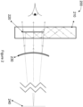
- Figure 2 illustrates an optical system 200 according to some examples.
- Optical system comprises an expansion waveguide 210 and an optically powered element 230 comprising holographic components to provide the optical power.
- Light may be input into expansion waveguide 210, and is expanded in at least one dimension, such that the size of the exit pupil increases in at least one dimension.
- Output element 220 interacts with the light and causes the light to be output towards optically powered element 230.
- Light is output collimated, or substantially collimated.
- Optically powered element 230 adds an angular offset to the collimated light, causing the collimated light to diverge and form a virtual image plane 240. This enables the user to perceive the image displayed by the optical system 200 to be located a certain distance behind the waveguide defined by the virtual image plane 240. This may reduce eye strain and headaches for some users, leading to a better user experience.
- the optical element 230 may be transparent or semi transparent, allowing a user to look through the optically powered element 230 and observe objects beyond the optical element 230.
- the optical geometry of the optical system may allow the user to still see imagery overlaid with real objects in the user's field of view.
- the optically powered element 230 may comprise a thin positive meniscus (convex-concave) shaped element.
- the convex side facing the user may be coated with a partially reflective coating (beam splitter coating) which would reflect light emitted from the waveguide back towards the user whilst causing the collimated light emitted from the waveguide to diverge forming a virtual image plane 240.
- the convex side facing away from the user may be shaped in order to minimise any aberrations of the outside world view when viewed through the optically powered element 230.
- the optical system 200 may be configured to compensate for the effect of the optical system on external light passing through the waveguide 210 and/or optically powered element 230 such that the outside scenery is not distorted.
- compensation may comprise an adaptation and/or addition to the optically powered element 230.
- the compensation may comprise a separate optical element.
- collimated light may be input into waveguide 210.
- uncollimated light may be input into the waveguide 210 and the light may be collimated by a component of the waveguide 210.
- the optically powered element may be coupled to the waveguide 230.
- the optically powered element 230 may comprise a holographic component which gives the optically powered element 230 optical power. This may allow the optical power to be varied by changing the phase of light input to the optically powered element 330.
- the holographic component may be static, such that it does not vary. In some examples the holographic component may be dynamic, such that it's properties can be varied. In some examples the dynamic holographic component may comprise an addressable and switchable reflective screen, such as liquid crystal display. This may allow the optical power to be varied by changing the phase of light and/or by changing the properties of the holographic component.
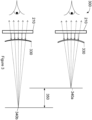
- Adjustable optical system 300 may be substantially similar to optical system 200 described in relation to Figure 2 .
- Adjustable optical system 300 comprises an expansion waveguide 210 and an adjustable optically powered element 330.
- the expansion waveguide 210 may be substantially similar to the expansion waveguide 210 described in relation to Figure 2 .
- Adjustable optical system may be controlled to alter the optical power of the system.
- the optically powered element 330 may be controlled to vary the optical power.
- the optical power may be varied into at least two states. In a first state the adjustable optically powered element 330 has a first optical power, leading to a virtual image plane 340a at a first distance from the user. In a second state the adjustable optically powered element 330 has a second optical power, different from the first optical power, leading to a virtual image plane 340b at a second distance from the user. The difference in optical power of the first state and second state cause a difference in position 350 of the virtual planes 340a, 340b.
- the adjustable optically powered element 330 may adjust it's optical power based on tracking information of the user's eyes, such as a focus or gaze direction of the eyes.
- the adjustable optically powered element 330 may be continuously adjustable between two points. In some examples the adjustable optically powered element 330 may be discretely variable, such that the adjustable optically powered element 330 may be set to a finite number of optical powers between two points.
- the adjustable optically powered element 330 may be varied in optical power by adjusting the curvature of the adjustable optically powered element 330. Adjusting the curvature may result in the image plane changing, but the focal point may fall on the same axis, i.e. the focal points may all be located on a line that is perpendicular to the output surface of the waveguide.
- the adjustable optically powered element 330 may be varied in optical power by adjusting the shape of the adjustable optically powered element 330. Adjusting the shape may result in the image plane changing, and the focal point may fall on a different axis, i.e. the focal points are not all located on a line that is perpendicular to the output surface of the waveguide.
- adjustable optically powered element 330 may be varied in optical power between having no optical power (i.e. substantially flat with focus at infinity) and any other focal point.
- the adjustable optically powered element 330 may comprise a microelectromechanical system (MEMS), and/or a piezoelectric device. In some examples the adjustable optically powered element 330 may comprise a electronically active element such as a reflective liquid crystal. In some examples the adjustable optically powered element 330 may comprise a, diffractive, pneumatic, and/or hydraulic device.
- MEMS microelectromechanical system
- the adjustable optically powered element 330 may comprise a piezoelectric device.
- the adjustable optically powered element 330 may comprise a electronically active element such as a reflective liquid crystal.
- the adjustable optically powered element 330 may comprise a, diffractive, pneumatic, and/or hydraulic device.
- the optically powered element 330 may comprise a holographic lens of fixed optical power. This may allow the lens to be tuned for wavelength, therefore able to maintain high transmission compared to a traditional silver mirror and able to be colour selective.
- the fixed holographic lens of fixed optical power may additionally or alternatively be tuned for angle. This may allow the lens to be angularly selective i.e. reflect incoming angles from a known field of view but transmit all other light.
- the holographic lens of fixed optical power may be substantially flat and/or thin - i.e. formed from a holographic layer between two glass or plastic plates, in comparison to a traditional lens or mirror arrangement where the element is typically curved and/or potentially thick. If the holographic lens is then placed in line with the eye, being a thin and/or flat element mitigates any distortion being imparted on the real world. In some examples where the lens element is placed in line with the waveguide, using a thin/flat holographic lens could also be integrated as a protective cover for the waveguide as well.
- the optically powered element 330 may comprise a holographic lens of variable function, such as variable power or reflectivity.
- a holographic lens of variable function may offer all the same features as the holographic lens of fixed optical power.
- the optical power may be varied either through electrical manipulation or physical manipulation of the holographic medium.
- the reflectivity may be varied to manipulate reflection intensity or the ability to "switch off" the hologram (and hence reflection) entirely.
- the holographic lens of variable function may be substantially flat and/or thin similar to the holographic lens of fixed optical power.
- Holographic lenses may also be stacked together to form various functions. For example you could stack a holographic lenses for green and red light may be stacked, wherein they have different optical powers or reflectivity.
- the adjustable optically powered element 330 may comprise a thin positive meniscus (convex-concave) shaped element.
- the convex side facing the user may be coated with a partially reflective coating (beam splitter coating) which would reflect light emitted from the waveguide back towards the user whilst causing the collimated light emitted from the waveguide to diverge forming a virtual image plane 240.
- the convex side facing away from the user may be shaped in order to minimise any aberrations of the outside world view when viewed through the adjustable optically powered element 330.
- FIG 4 illustrates a folded optical system 400 according to some examples.
- the folded optical system 400 may be substantially similar to the optical system 200 described in relation to Figure 2 and the adjustable optical system 300 described in relation to Figure 3 .
- Folded optical system 400 comprises a waveguide 410, an optically powered element 430, and a combiner element 440.
- Waveguide 410 receives light, and outputs collimated light towards optically powered element 430.
- Optically powered element 430 adds an angular offset to the reflected light and reflects it through waveguide 410 to combiner 440.
- Combiner 440 is at least semi-transparent such that the user is able to observe outside scenery through combiner 440.
- the combiner reflects light from the waveguide 410 towards the eye of the user, such that the image plane 240 appears to be behind the combiner 440.
- the optically powered element 430 may be opaque, as there is no reason why the optically powered element 430 is required to be looked through.
- the optically powered element 440 may also be highly reflective.
- Folded optical system 400 may be used in head up displays (HUD) or head down displays, or any other suitable system.
- HUD head up displays
- head down displays or any other suitable system.
- FIG 5 illustrates an offset optical system 500.
- Offset optical system 500 may be substantially similar to the optical system 200 described in relation to Figure 2 , the adjustable optical system 300 described in relation to Figure 3 , and the folded optical system 400 described in relation to Figure 4 .
- Offset optical system 500 comprises an offset waveguide 510 and an offset optically powered element 530.
- Offset waveguide receives offset input light 550, which is expanded in at least one dimension and propagates down offset waveguide 510. Due to the presence of element 520 the light is output from the offset waveguide 510.
- the type of the offset waveguide 510 may lead to light being emitted on both sides of the offset waveguide 510, as illustrated in Figure 5 .
- User light 560 emitted towards the offset optically powered element 530 is reflected by offset optically powered element 530 and an angular offset added such that the light diverges and forms a virtual image plane 240. The light then passes through the waveguide again such that the user observes the image to be formed at the virtual plane 540.
- Non-user light 570 is emitted away from the user's eye and away from the offset optically powered element 530 such that it is not received by the user. This reduces the chance of a double image being observed by the user.
- the offset optically powered element 530 may be designed, in combination with the offset waveguide 510 to ensure that light received from the offset optically powered element 530 appear to be focused at virtual image plane 240.
- the offset optically powered element 530 may comprise a thin positive meniscus (convex-concave) shaped element.
- the convex side facing the user may be coated with a partially reflective coating (beam splitter coating) which would reflect light emitted from the waveguide back towards the user whilst causing the collimated light emitted from the waveguide to diverge forming a virtual image plane 240.
- the convex side facing away from the user may be shaped in order to minimise any aberrations of the outside world view when viewed through the offset optically powered element 530.
- FIG. 6 illustrates a birdbath style optical system 600 according to some examples, where the light does not pass back through the waveguide.
- Birdbath style optical system 600 comprises a birdbath waveguide 610, a semi-reflective mirror 620, and a birdbath optically powered element 630.
- the birdbath waveguide is configured to receive light and output collimated light towards the semi-reflective mirror 620.
- the semi-reflective mirror 620 allows all or substantially all of light to pass from the birdbath waveguide 610 towards the birdbath optically powered element 630.
- Birdbath optically powered element 630 imparts an angular offset onto the light such that it diverges and forms a virtual image plane 240.
- the light is reflected from birdbath optically powered element towards the semi-reflective mirror 620.
- Semi-reflective mirror 620 reflects the light from the birdbath optically powered element 630 towards the user.
- the arrangement of Figure 6 allows for at least one of the birdbath waveguide 610 and birdbath optically powered element 630 to be opaque, or substantially opaque.
- the semi-reflective mirror may appear transparent to visible light or substantially transparent to visible light from the viewing angle of the user.
- optically powered element may be flat or substantially flat.
- a holographic component or lens may be defined as an optical device that constructs new converging or diverging wavefronts defined by the optical power of the holographic component or lens through the principles of diffraction.
Landscapes
- Physics & Mathematics (AREA)
- General Physics & Mathematics (AREA)
- Optics & Photonics (AREA)
- Optical Couplings Of Light Guides (AREA)
Claims (13)
- Optisches System zum Darstellen eines Bilds für ein Auge eines Benutzers, wobei das System umfasst:einen Wellenleiter (510), der konfiguriert ist, um kollimiertes Licht in Richtung eines optisch angetriebenen Elements (530) auszugeben, das mindestens eine holografische Komponente (520) umfasst, um optische Leistung zu erzeugen;wobei das optisch angetriebene Element konfiguriert ist, um das ausgegebene kollimierte Licht von dem Wellenleiter zu empfangen und das empfangene Licht in Richtung des Auges des Benutzers zu richten und dem gerichteten Licht einen Winkelversatz zu verleihen, sodass das gerichtete Licht eine virtuelle Bildebene (240) bildet,wobei das optisch angetriebene Element konfiguriert ist, um das ausgegebene kollimierte Licht vom Wellenleiter zu empfangen und das empfangene Licht durch den Wellenleiter in Richtung des Auges des Benutzers zu leiten,wobei das optisch angetriebene Element in Bezug auf eine optische Achse des Wellenleiters geneigt ist, undwobei der Wellenleiter konfiguriert ist, um einen Abschnitt (570) des empfangenen Lichts von einer gegenüberliegenden Seite des Wellenleiters, von der das kollimierte Licht in Richtung des optisch angetriebenen Elements emittiert wird, von dem Auge des Benutzers weg zu emittieren, und von dem geneigten optisch angetriebenen Element reflektiertes Licht durch den Wellenleiter in Richtung des Auges eines Benutzers emittiert wird.
- Optisches System nach einem vorstehenden Anspruch, wobei der Wellenleiter (510) konfiguriert ist, um das kollimierte Licht in mindestens einer Dimension aufzuweiten.
- Optisches System nach Anspruch 2, wobei die optische Leistung durch Verändern der Form und/oder Krümmung des optisch angetriebenen Elements (530) eingestellt wird.
- Optisches System nach einem vorstehenden Anspruch, wobei die holografische Komponente (520) dynamisch einstellbar ist.
- Optisches System nach Anspruch 4, wobei die holographische Komponente (520) kontinuierlich dynamisch einstellbar oder diskret dynamisch einstellbar ist.
- Optisches System nach Anspruch 4 oder 5, wobei die holografische Komponente (520) dynamisch einstellbar ist, um die optische Leistung zu verändern.
- Optisches System nach einem vorstehenden Anspruch, wobei die optische Leistung durch Verändern der Phase des von dem optisch angetriebenen Element (530) empfangenen Lichts eingestellt wird.
- Optisches System nach einem vorstehenden Anspruch, wobei die Form und/oder Krümmung des optisch angetriebenen Elements (530) kontinuierlich veränderbar oder diskret veränderbar ist.
- Optisches System nach einem vorstehenden Anspruch, das weiter einen Kombinierer in einem optischen Pfad zwischen dem Wellenleiter und dem Auge des Benutzers umfasst.
- Optisches System nach einem vorstehenden Anspruch, wobei das optisch angetriebene Element (530) eine Beschichtung mit hohem Reflexionsgrad aufweist.
- Optisches System nach einem vorstehenden Anspruch, wobei das optisch angetriebene Element (530) im Wesentlichen flach ist.
- Durchsichtige Anzeige, die ein optisches System nach einem der Ansprüche 1-11 umfasst.
- Durchsichtige Anzeige nach Anspruch 12, wobei die durchsichtige Anzeige eines ist von: einer Kopf montierten Anzeige, einer Head-up-Anzeige oder einer Head-down-Anzeige.
Priority Applications (1)
| Application Number | Priority Date | Filing Date | Title |
|---|---|---|---|
| EP24212373.5A EP4550030A3 (de) | 2020-03-24 | 2021-03-08 | Optisches system |
Applications Claiming Priority (3)
| Application Number | Priority Date | Filing Date | Title |
|---|---|---|---|
| EP20275063.4A EP3885799A1 (de) | 2020-03-24 | 2020-03-24 | Optisches system |
| GBGB2004220.6A GB202004220D0 (en) | 2020-03-24 | 2020-03-24 | Optical system |
| PCT/GB2021/050572 WO2021191584A1 (en) | 2020-03-24 | 2021-03-08 | Optical system |
Related Child Applications (1)
| Application Number | Title | Priority Date | Filing Date |
|---|---|---|---|
| EP24212373.5A Division EP4550030A3 (de) | 2020-03-24 | 2021-03-08 | Optisches system |
Publications (2)
| Publication Number | Publication Date |
|---|---|
| EP4127787A1 EP4127787A1 (de) | 2023-02-08 |
| EP4127787B1 true EP4127787B1 (de) | 2024-11-13 |
Family
ID=74859486
Family Applications (2)
| Application Number | Title | Priority Date | Filing Date |
|---|---|---|---|
| EP21710337.3A Active EP4127787B1 (de) | 2020-03-24 | 2021-03-08 | Optisches system |
| EP24212373.5A Pending EP4550030A3 (de) | 2020-03-24 | 2021-03-08 | Optisches system |
Family Applications After (1)
| Application Number | Title | Priority Date | Filing Date |
|---|---|---|---|
| EP24212373.5A Pending EP4550030A3 (de) | 2020-03-24 | 2021-03-08 | Optisches system |
Country Status (5)
| Country | Link |
|---|---|
| US (1) | US12607852B2 (de) |
| EP (2) | EP4127787B1 (de) |
| KR (2) | KR102849359B1 (de) |
| GB (1) | GB2594356B (de) |
| WO (1) | WO2021191584A1 (de) |
Families Citing this family (1)
| Publication number | Priority date | Publication date | Assignee | Title |
|---|---|---|---|---|
| WO2021191584A1 (en) | 2020-03-24 | 2021-09-30 | Bae Systems Plc | Optical system |
Family Cites Families (19)
| Publication number | Priority date | Publication date | Assignee | Title |
|---|---|---|---|---|
| CN102402005B (zh) | 2011-12-06 | 2015-11-25 | 北京理工大学 | 自由曲面双焦面单目立体头盔显示器装置 |
| US10502876B2 (en) * | 2012-05-22 | 2019-12-10 | Microsoft Technology Licensing, Llc | Waveguide optics focus elements |
| ES2788756T3 (es) | 2012-12-10 | 2020-10-22 | Bae Systems Plc | Mejoras en y relacionadas con sistemas de visualización |
| EP2818910A1 (de) | 2013-06-26 | 2014-12-31 | BAE Systems PLC | Anzeige mit einem optischen Wellenleiter zum Anzeigen eines Bilds |
| US10746994B2 (en) * | 2014-08-07 | 2020-08-18 | Microsoft Technology Licensing, Llc | Spherical mirror having a decoupled aspheric |
| US10108011B2 (en) | 2015-01-20 | 2018-10-23 | Microsoft Technology Licensing, Llc | Microsphere spaced waveguide display |
| EP3091740A1 (de) * | 2015-05-08 | 2016-11-09 | BAE Systems PLC | Verbesserungen an und im zusammenhang mit anzeigen |
| US20180045960A1 (en) | 2015-12-02 | 2018-02-15 | Augmenteum, LLC. | System for and method of projecting augmentation imagery in a head-mounted display |
| DE102016115938A1 (de) * | 2016-08-26 | 2018-03-01 | Carl Zeiss Jena Gmbh | Wellenleiter sowie Vorrichtungen zur Dateneinspiegelung |
| KR102664386B1 (ko) | 2016-11-28 | 2024-05-09 | 삼성전자주식회사 | 홀로그래픽 디스플레이 장치용 백라이트 유닛 및 이를 포함하는 홀로그래픽 디스플레이 장치 |
| US9711072B1 (en) * | 2016-12-01 | 2017-07-18 | Varjo Technologies Oy | Display apparatus and method of displaying using focus and context displays |
| IL307602A (en) * | 2017-02-23 | 2023-12-01 | Magic Leap Inc | Variable focus virtual imagers based on polarization conversion |
| US10642045B2 (en) | 2017-04-07 | 2020-05-05 | Microsoft Technology Licensing, Llc | Scanner-illuminated LCOS projector for head mounted display |
| US10859834B2 (en) * | 2017-07-03 | 2020-12-08 | Holovisions | Space-efficient optical structures for wide field-of-view augmented reality (AR) eyewear |
| CN108490756B (zh) | 2018-03-01 | 2022-03-25 | 北京理工大学 | 一种基于波导传输的全息显示器 |
| US10852558B2 (en) * | 2018-08-24 | 2020-12-01 | Facebook Technologies, Llc | Near-eye display (NED) system and method using flexible reflector |
| CN110488490A (zh) * | 2019-07-22 | 2019-11-22 | 渭南正和电子科技有限公司 | 一种紧凑型增强现实近眼显示装置 |
| WO2021191584A1 (en) | 2020-03-24 | 2021-09-30 | Bae Systems Plc | Optical system |
| EP3885799A1 (de) | 2020-03-24 | 2021-09-29 | BAE SYSTEMS plc | Optisches system |
-
2021
- 2021-03-08 WO PCT/GB2021/050572 patent/WO2021191584A1/en not_active Ceased
- 2021-03-08 US US17/913,696 patent/US12607852B2/en active Active
- 2021-03-08 KR KR1020227036533A patent/KR102849359B1/ko active Active
- 2021-03-08 EP EP21710337.3A patent/EP4127787B1/de active Active
- 2021-03-08 KR KR1020257027565A patent/KR20250133447A/ko active Pending
- 2021-03-08 EP EP24212373.5A patent/EP4550030A3/de active Pending
- 2021-03-08 GB GB2103202.4A patent/GB2594356B/en active Active
Also Published As
| Publication number | Publication date |
|---|---|
| GB202103202D0 (en) | 2021-04-21 |
| US20230111272A1 (en) | 2023-04-13 |
| EP4550030A3 (de) | 2025-07-16 |
| WO2021191584A1 (en) | 2021-09-30 |
| KR102849359B1 (ko) | 2025-08-26 |
| GB2594356B (en) | 2024-05-22 |
| KR20250133447A (ko) | 2025-09-05 |
| KR20220148315A (ko) | 2022-11-04 |
| GB2594356A (en) | 2021-10-27 |
| US12607852B2 (en) | 2026-04-21 |
| EP4550030A2 (de) | 2025-05-07 |
| EP4127787A1 (de) | 2023-02-08 |
Similar Documents
| Publication | Publication Date | Title |
|---|---|---|
| US20210349316A1 (en) | Diffraction based monochromatic head up display for airborne applications | |
| US11940625B2 (en) | Light-guide display with reflector | |
| EP3889670B1 (de) | Optisches system für eine anzeige mit einem ausseraxialen projektor | |
| KR102833128B1 (ko) | 원통형 도파관을 갖는 광학 시스템 | |
| US11474357B2 (en) | Augmented reality display device | |
| WO2017150636A1 (en) | Head Mounted Display Using Spatial Light Modulator To Generate a Holographic Image | |
| EP3990965B1 (de) | Pupillenrelaissystem | |
| JP7093729B2 (ja) | シースルー表示システム | |
| US9389422B1 (en) | Eyepiece for head wearable display using partial and total internal reflections | |
| JP2025502162A (ja) | 複数のインカプラ導波路に光を方向付けるための装置及び方法 | |
| EP4127787B1 (de) | Optisches system | |
| EP3885799A1 (de) | Optisches system | |
| CN115335732A (zh) | 光学系统 | |
| EP4602409A1 (de) | Optische linse für eine anzeige der erweiterten realität | |
| JP2025145078A (ja) | 画像表示装置 | |
| 유찬형 | Enhanced waveguide-based near-eye displays with polarization multiplexing | |
| CN121713106A (zh) | 变形定向照明装置 | |
| CN117950189A (zh) | 虚像显示装置 | |
| CN117075342A (zh) | 近眼显示装置 | |
| JP2021086074A (ja) | 透過型画像表示装置 |
Legal Events
| Date | Code | Title | Description |
|---|---|---|---|
| STAA | Information on the status of an ep patent application or granted ep patent |
Free format text: STATUS: UNKNOWN |
|
| STAA | Information on the status of an ep patent application or granted ep patent |
Free format text: STATUS: THE INTERNATIONAL PUBLICATION HAS BEEN MADE |
|
| PUAI | Public reference made under article 153(3) epc to a published international application that has entered the european phase |
Free format text: ORIGINAL CODE: 0009012 |
|
| STAA | Information on the status of an ep patent application or granted ep patent |
Free format text: STATUS: REQUEST FOR EXAMINATION WAS MADE |
|
| 17P | Request for examination filed |
Effective date: 20220926 |
|
| AK | Designated contracting states |
Kind code of ref document: A1 Designated state(s): AL AT BE BG CH CY CZ DE DK EE ES FI FR GB GR HR HU IE IS IT LI LT LU LV MC MK MT NL NO PL PT RO RS SE SI SK SM TR |
|
| DAV | Request for validation of the european patent (deleted) | ||
| DAX | Request for extension of the european patent (deleted) | ||
| P01 | Opt-out of the competence of the unified patent court (upc) registered |
Effective date: 20230526 |
|
| GRAP | Despatch of communication of intention to grant a patent |
Free format text: ORIGINAL CODE: EPIDOSNIGR1 |
|
| STAA | Information on the status of an ep patent application or granted ep patent |
Free format text: STATUS: GRANT OF PATENT IS INTENDED |
|
| INTG | Intention to grant announced |
Effective date: 20240611 |
|
| RIN1 | Information on inventor provided before grant (corrected) |
Inventor name: MACKEN, IAN THOMAS Inventor name: MILLS, RORY THOMAS ALEXANDER |
|
| GRAS | Grant fee paid |
Free format text: ORIGINAL CODE: EPIDOSNIGR3 |
|
| GRAA | (expected) grant |
Free format text: ORIGINAL CODE: 0009210 |
|
| STAA | Information on the status of an ep patent application or granted ep patent |
Free format text: STATUS: THE PATENT HAS BEEN GRANTED |
|
| AK | Designated contracting states |
Kind code of ref document: B1 Designated state(s): AL AT BE BG CH CY CZ DE DK EE ES FI FR GB GR HR HU IE IS IT LI LT LU LV MC MK MT NL NO PL PT RO RS SE SI SK SM TR |
|
| REG | Reference to a national code |
Ref country code: GB Ref legal event code: FG4D |
|
| REG | Reference to a national code |
Ref country code: CH Ref legal event code: EP |
|
| REG | Reference to a national code |
Ref country code: IE Ref legal event code: FG4D |
|
| REG | Reference to a national code |
Ref country code: DE Ref legal event code: R096 Ref document number: 602021021763 Country of ref document: DE |
|
| REG | Reference to a national code |
Ref country code: NL Ref legal event code: FP |
|
| REG | Reference to a national code |
Ref country code: LT Ref legal event code: MG9D |
|
| PG25 | Lapsed in a contracting state [announced via postgrant information from national office to epo] |
Ref country code: PT Free format text: LAPSE BECAUSE OF FAILURE TO SUBMIT A TRANSLATION OF THE DESCRIPTION OR TO PAY THE FEE WITHIN THE PRESCRIBED TIME-LIMIT Effective date: 20250313 Ref country code: IS Free format text: LAPSE BECAUSE OF FAILURE TO SUBMIT A TRANSLATION OF THE DESCRIPTION OR TO PAY THE FEE WITHIN THE PRESCRIBED TIME-LIMIT Effective date: 20250313 Ref country code: HR Free format text: LAPSE BECAUSE OF FAILURE TO SUBMIT A TRANSLATION OF THE DESCRIPTION OR TO PAY THE FEE WITHIN THE PRESCRIBED TIME-LIMIT Effective date: 20241113 |
|
| PG25 | Lapsed in a contracting state [announced via postgrant information from national office to epo] |
Ref country code: FI Free format text: LAPSE BECAUSE OF FAILURE TO SUBMIT A TRANSLATION OF THE DESCRIPTION OR TO PAY THE FEE WITHIN THE PRESCRIBED TIME-LIMIT Effective date: 20241113 |
|
| REG | Reference to a national code |
Ref country code: AT Ref legal event code: MK05 Ref document number: 1742101 Country of ref document: AT Kind code of ref document: T Effective date: 20241113 |
|
| PG25 | Lapsed in a contracting state [announced via postgrant information from national office to epo] |
Ref country code: BG Free format text: LAPSE BECAUSE OF FAILURE TO SUBMIT A TRANSLATION OF THE DESCRIPTION OR TO PAY THE FEE WITHIN THE PRESCRIBED TIME-LIMIT Effective date: 20241113 |
|
| PG25 | Lapsed in a contracting state [announced via postgrant information from national office to epo] |
Ref country code: ES Free format text: LAPSE BECAUSE OF FAILURE TO SUBMIT A TRANSLATION OF THE DESCRIPTION OR TO PAY THE FEE WITHIN THE PRESCRIBED TIME-LIMIT Effective date: 20241113 |
|
| PG25 | Lapsed in a contracting state [announced via postgrant information from national office to epo] |
Ref country code: NO Free format text: LAPSE BECAUSE OF FAILURE TO SUBMIT A TRANSLATION OF THE DESCRIPTION OR TO PAY THE FEE WITHIN THE PRESCRIBED TIME-LIMIT Effective date: 20250213 |
|
| PG25 | Lapsed in a contracting state [announced via postgrant information from national office to epo] |
Ref country code: LV Free format text: LAPSE BECAUSE OF FAILURE TO SUBMIT A TRANSLATION OF THE DESCRIPTION OR TO PAY THE FEE WITHIN THE PRESCRIBED TIME-LIMIT Effective date: 20241113 Ref country code: GR Free format text: LAPSE BECAUSE OF FAILURE TO SUBMIT A TRANSLATION OF THE DESCRIPTION OR TO PAY THE FEE WITHIN THE PRESCRIBED TIME-LIMIT Effective date: 20250214 Ref country code: AT Free format text: LAPSE BECAUSE OF FAILURE TO SUBMIT A TRANSLATION OF THE DESCRIPTION OR TO PAY THE FEE WITHIN THE PRESCRIBED TIME-LIMIT Effective date: 20241113 |
|
| PG25 | Lapsed in a contracting state [announced via postgrant information from national office to epo] |
Ref country code: PL Free format text: LAPSE BECAUSE OF FAILURE TO SUBMIT A TRANSLATION OF THE DESCRIPTION OR TO PAY THE FEE WITHIN THE PRESCRIBED TIME-LIMIT Effective date: 20241113 |
|
| PG25 | Lapsed in a contracting state [announced via postgrant information from national office to epo] |
Ref country code: RS Free format text: LAPSE BECAUSE OF FAILURE TO SUBMIT A TRANSLATION OF THE DESCRIPTION OR TO PAY THE FEE WITHIN THE PRESCRIBED TIME-LIMIT Effective date: 20250213 |
|
| PG25 | Lapsed in a contracting state [announced via postgrant information from national office to epo] |
Ref country code: SM Free format text: LAPSE BECAUSE OF FAILURE TO SUBMIT A TRANSLATION OF THE DESCRIPTION OR TO PAY THE FEE WITHIN THE PRESCRIBED TIME-LIMIT Effective date: 20241113 |
|
| PG25 | Lapsed in a contracting state [announced via postgrant information from national office to epo] |
Ref country code: DK Free format text: LAPSE BECAUSE OF FAILURE TO SUBMIT A TRANSLATION OF THE DESCRIPTION OR TO PAY THE FEE WITHIN THE PRESCRIBED TIME-LIMIT Effective date: 20241113 |
|
| PG25 | Lapsed in a contracting state [announced via postgrant information from national office to epo] |
Ref country code: EE Free format text: LAPSE BECAUSE OF FAILURE TO SUBMIT A TRANSLATION OF THE DESCRIPTION OR TO PAY THE FEE WITHIN THE PRESCRIBED TIME-LIMIT Effective date: 20241113 |
|
| PG25 | Lapsed in a contracting state [announced via postgrant information from national office to epo] |
Ref country code: RO Free format text: LAPSE BECAUSE OF FAILURE TO SUBMIT A TRANSLATION OF THE DESCRIPTION OR TO PAY THE FEE WITHIN THE PRESCRIBED TIME-LIMIT Effective date: 20241113 |
|
| PG25 | Lapsed in a contracting state [announced via postgrant information from national office to epo] |
Ref country code: SK Free format text: LAPSE BECAUSE OF FAILURE TO SUBMIT A TRANSLATION OF THE DESCRIPTION OR TO PAY THE FEE WITHIN THE PRESCRIBED TIME-LIMIT Effective date: 20241113 |
|
| PG25 | Lapsed in a contracting state [announced via postgrant information from national office to epo] |
Ref country code: CZ Free format text: LAPSE BECAUSE OF FAILURE TO SUBMIT A TRANSLATION OF THE DESCRIPTION OR TO PAY THE FEE WITHIN THE PRESCRIBED TIME-LIMIT Effective date: 20241113 |
|
| PG25 | Lapsed in a contracting state [announced via postgrant information from national office to epo] |
Ref country code: IT Free format text: LAPSE BECAUSE OF FAILURE TO SUBMIT A TRANSLATION OF THE DESCRIPTION OR TO PAY THE FEE WITHIN THE PRESCRIBED TIME-LIMIT Effective date: 20241113 |
|
| REG | Reference to a national code |
Ref country code: DE Ref legal event code: R097 Ref document number: 602021021763 Country of ref document: DE |
|
| PG25 | Lapsed in a contracting state [announced via postgrant information from national office to epo] |
Ref country code: SE Free format text: LAPSE BECAUSE OF FAILURE TO SUBMIT A TRANSLATION OF THE DESCRIPTION OR TO PAY THE FEE WITHIN THE PRESCRIBED TIME-LIMIT Effective date: 20241113 |
|
| PLBE | No opposition filed within time limit |
Free format text: ORIGINAL CODE: 0009261 |
|
| STAA | Information on the status of an ep patent application or granted ep patent |
Free format text: STATUS: NO OPPOSITION FILED WITHIN TIME LIMIT |
|
| PG25 | Lapsed in a contracting state [announced via postgrant information from national office to epo] |
Ref country code: MC Free format text: LAPSE BECAUSE OF FAILURE TO SUBMIT A TRANSLATION OF THE DESCRIPTION OR TO PAY THE FEE WITHIN THE PRESCRIBED TIME-LIMIT Effective date: 20241113 |
|
| 26N | No opposition filed |
Effective date: 20250814 |
|
| REG | Reference to a national code |
Ref country code: CH Ref legal event code: H13 Free format text: ST27 STATUS EVENT CODE: U-0-0-H10-H13 (AS PROVIDED BY THE NATIONAL OFFICE) Effective date: 20251023 |
|
| PG25 | Lapsed in a contracting state [announced via postgrant information from national office to epo] |
Ref country code: LU Free format text: LAPSE BECAUSE OF NON-PAYMENT OF DUE FEES Effective date: 20250308 |
|
| REG | Reference to a national code |
Ref country code: BE Ref legal event code: MM Effective date: 20250331 |
|
| PG25 | Lapsed in a contracting state [announced via postgrant information from national office to epo] |
Ref country code: BE Free format text: LAPSE BECAUSE OF NON-PAYMENT OF DUE FEES Effective date: 20250331 |
|
| PG25 | Lapsed in a contracting state [announced via postgrant information from national office to epo] |
Ref country code: CH Free format text: LAPSE BECAUSE OF NON-PAYMENT OF DUE FEES Effective date: 20250331 |
|
| PG25 | Lapsed in a contracting state [announced via postgrant information from national office to epo] |
Ref country code: IE Free format text: LAPSE BECAUSE OF NON-PAYMENT OF DUE FEES Effective date: 20250308 |
|
| PGFP | Annual fee paid to national office [announced via postgrant information from national office to epo] |
Ref country code: NL Payment date: 20260219 Year of fee payment: 6 |
|
| PGFP | Annual fee paid to national office [announced via postgrant information from national office to epo] |
Ref country code: GB Payment date: 20260213 Year of fee payment: 6 |
|
| PGFP | Annual fee paid to national office [announced via postgrant information from national office to epo] |
Ref country code: DE Payment date: 20260216 Year of fee payment: 6 |
|
| PGFP | Annual fee paid to national office [announced via postgrant information from national office to epo] |
Ref country code: FR Payment date: 20260212 Year of fee payment: 6 |